Embed Size (px)
Citation preview
Rev draft h 6/18/12 Author John Propst Technical Review Pending by Bill Pancake
1
Aeronca Champ Hydraulic Toe Brake Conversion
By John Propst with Technical Review by Bill Pancake Abstract: This article covers the conversion of a 1946 Aeronca 7AC from mechanical drum brakes to hydraulic toe brakes using the WagAero conversion kit and STC’s. Background The original brakes on a 1946 Aeronca Champ are operated by left and right heel brakes located on the aircraft floor board in front of the front and rear rudder pedals. The heel brake pedals are operated independent of the rudder pedals. This is different than the heel brakes on Aeronca Chief aircraft, which are mounted on the rudder pedals and can be operated in conjunction with the rudder pedals. This is also different than toe brakes typically found on newer aircraft that are mounted on and operated in conjunction with the rudder pedals. Some pilots, including myself often experience difficulty in trying to operate the aircraft heel brakes while also operating the aircraft rudder pedals. On turf this is generally not an issue as brakes are seldom used while maneuvering the aircraft at high speeds. One exception might be during high cross wind landings on short fields. The need for concurrent operation of the aircraft brake pedals and rudder pedals is often desirable when attempting crosswind landings on hard surface runways. To have to choose between rudder and steering control or aircraft braking can often increase the safety risk, especially for less experienced pilots. To reduce this safety risk, the heel brake system is being replaced with rudder pedal mounted toe brakes. This toe brake system also incorporates hydraulic rather than mechanical actuated braking and involves replacing the existing mechanical drum brake system and “DMB” wheels with Cleveland hydraulic caliper brake system, brake rotors, and new Cleveland 6.00 – 6 wheels. Installation of the hydraulic brake cylinders requires the installation of two additional brackets welded to the aircraft airframe. The hydraulic brake system incorporates a double “valve” to block in the hydraulic brake fluid to the wheels and serve as the parking brake. The valve is actuated by a pull knob on the control panel. The new rear rudder pedal toe brake actuators and rudder pedals are connected to the front brake pedals and rudder pedals with solid tube connection links. The old cable links between the front and rear rudder pedals are removed and not used. The old heal brake pedals are removed and not used. The hydraulic braking system has a single brake-fluid reservoir mounted on the firewall. The installation of the hydraulic wheel and brake system and the toe operated brake pedals is covered by STC SA34CH and STC SA507CH.
Rev draft h 6/18/12 Author John Propst Technical Review Pending by Bill Pancake
2
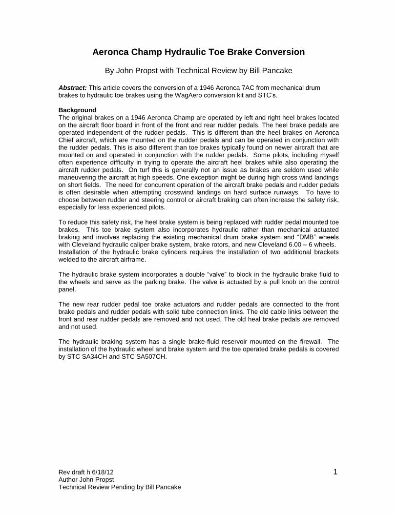
Conversion Kit Contents and Details Wheels and brakes The new wheels and brakes were received in the Cleveland factory packing box. The box was tagged as WagAero item SAR-9. The box contained two completely assembled wheel units including wheels, bearings, brake disks, and plain hubcaps. The box also contained two complete disk brake caliper assemblies, including mounting bracket, brake shoes, and brake line fittings. Brake Details Cleveland Wheels and Brakes Parker Hannifin Corp Aircraft Wheel and Brake Div. Avon Ohio 44011 Part No: 30-19 Torque Backplate tie bolts 75-80 in-lbs FAA-TSO-C26a Mfg. 01/11
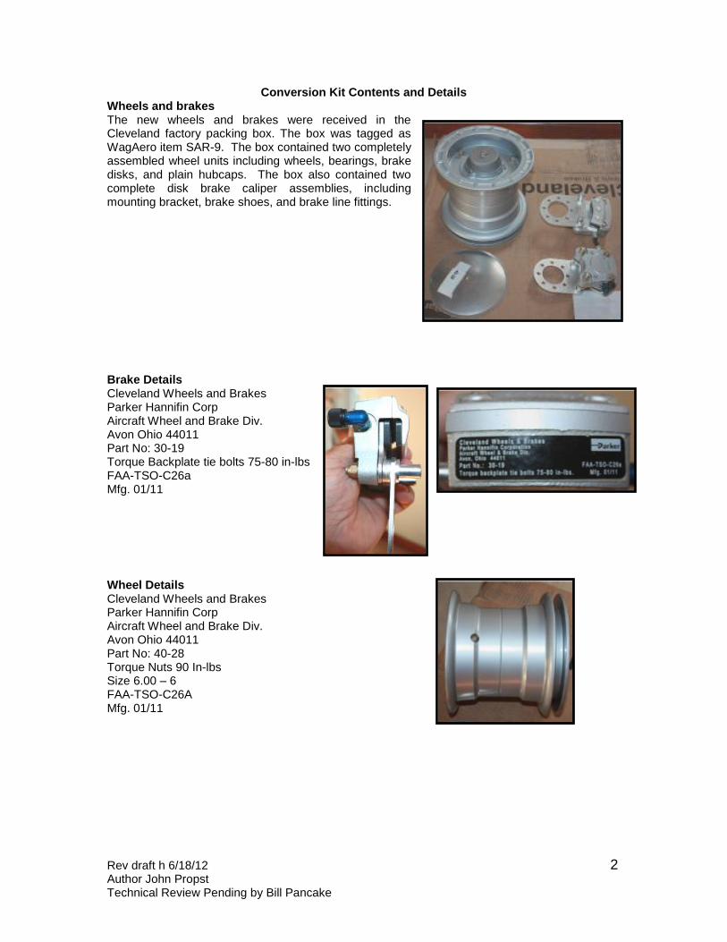
Wheel Details Cleveland Wheels and Brakes Parker Hannifin Corp Aircraft Wheel and Brake Div. Avon Ohio 44011 Part No: 40-28 Torque Nuts 90 In-lbs Size 6.00 – 6 FAA-TSO-C26A Mfg. 01/11
Rev draft h 6/18/12 Author John Propst Technical Review Pending by Bill Pancake
3
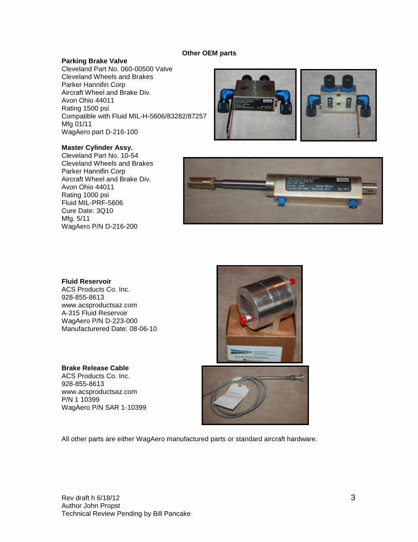
Other OEM parts Parking Brake Valve Cleveland Part No. 060-00500 Valve Cleveland Wheels and Brakes Parker Hannifin Corp Aircraft Wheel and Brake Div. Avon Ohio 44011 Rating 1500 psi Compatible with Fluid MIL-H-5606/83282/87257 Mfg 01/11 WagAero part D-216-100
Master Cylinder Assy. Cleveland Part No. 10-54 Cleveland Wheels and Brakes Parker Hannifin Corp Aircraft Wheel and Brake Div. Avon Ohio 44011 Rating 1000 psi Fluid MIL-PRF-5606 Cure Date: 3Q10 Mfg. 5/11 WagAero P/N D-216-200
Fluid Reservoir ACS Products Co. Inc. 928-855-8613 www.acsproductsaz.com A-315 Fluid Reservoir WagAero P/N D-223-000 Manufacturered Date: 08-06-10 Brake Release Cable ACS Products Co. Inc. 928-855-8613 www.acsproductsaz.com P/N 1 10399 WagAero P/N SAR 1-10399 All other parts are either WagAero manufactured parts or standard aircraft hardware.

Rev draft h 6/18/12 Author John Propst Technical Review Pending by Bill Pancake
4
Toe Brake and Rudder Assembly
These photos show the right side front and rear rudder and toe brake pedals temporarily mounted for parts fitting.
Rev draft h 6/18/12 Author John Propst Technical Review Pending by Bill Pancake
5
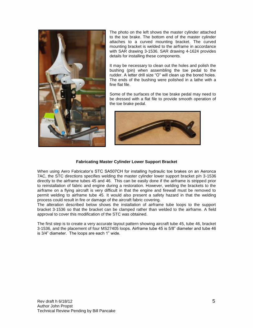
The photo on the left shows the master cylinder attached to the toe brake. The bottom end of the master cylinder attaches to a curved mounting bracket. The curved mounting bracket is welded to the airframe in accordance with SAR drawing 3-1536. SAR drawing 4-1624 provides details for installing these components. It may be necessary to clean out the holes and polish the bushing (pin) when assembling the toe pedal to the rudder. A letter drill size “O” will clean up the bored holes. The ends of the bushing were polished in a lathe with a fine flat file. Some of the surfaces of the toe brake pedal may need to be dressed with a flat file to provide smooth operation of the toe brake pedal.
Fabricating Master Cylinder Lower Support Bracket
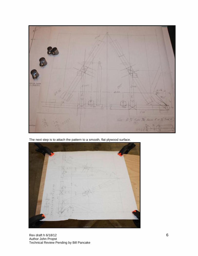
When using Aero Fabricator’s STC SA507CH for installing hydraulic toe brakes on an Aeronca 7AC, the STC directions specifies welding the master cylinder lower support bracket p/n 3-1536 directly to the airframe tubes 45 and 46. This can be easily done if the airframe is stripped prior to reinstallation of fabric and engine during a restoration. However, welding the brackets to the airframe on a flying aircraft is very difficult in that the engine and firewall must be removed to permit welding to airframe tube 45. It would also present a safety hazard in that the welding process could result in fire or damage of the aircraft fabric covering. The alteration described below shows the installation of airframe tube loops to the support bracket 3-1536 so that the bracket can be clamped rather than welded to the airframe. A field approval to cover this modification of the STC was obtained. The first step is to create a very accurate layout pattern showing aircraft tube 45, tube 46, bracket 3-1536, and the placement of four MS27405 loops. Airframe tube 45 is 5/8” diameter and tube 46 is 3/4” diameter. The loops are each 1” wide.
Rev draft h 6/18/12 Author John Propst Technical Review Pending by Bill Pancake
6
The next step is to attach the pattern to a smooth, flat plywood surface.
Rev draft h 6/18/12 Author John Propst Technical Review Pending by Bill Pancake
7
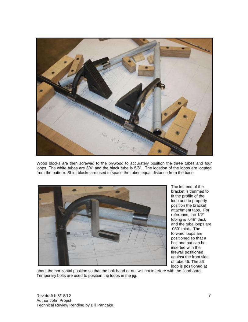
Wood blocks are then screwed to the plywood to accurately position the three tubes and four loops. The white tubes are 3/4" and the black tube is 5/8”. The location of the loops are located from the pattern. Shim blocks are used to space the tubes equal distance from the base.
The left end of the bracket is trimmed to fit the profile of the loop and to properly position the bracket attachment tabs. For reference, the 1/2” tubing is .049” thick and the tube loops are .050” thick. The forward loops are positioned so that a bolt and nut can be inserted with the firewall positioned against the front side of tube 45. The aft loop is positioned at
about the horizontal position so that the bolt head or nut will not interfere with the floorboard. Temporary bolts are used to position the loops in the jig.
Rev draft h 6/18/12 Author John Propst Technical Review Pending by Bill Pancake
8
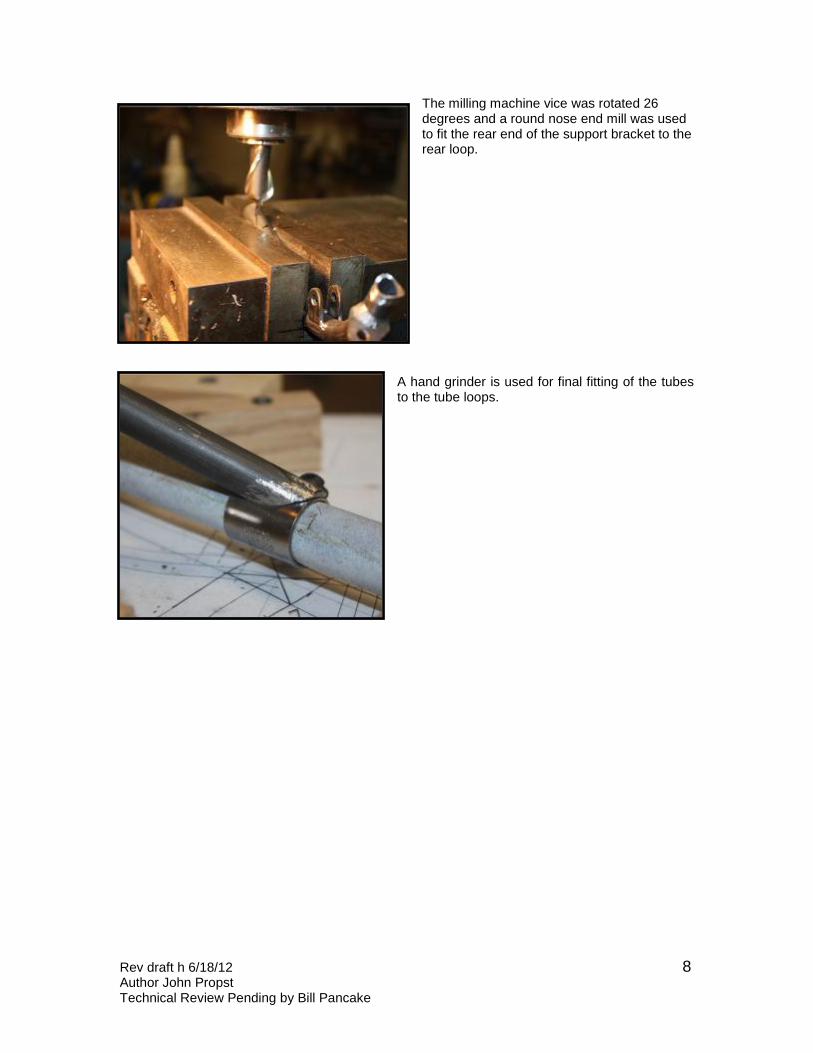
The milling machine vice was rotated 26 degrees and a round nose end mill was used to fit the rear end of the support bracket to the rear loop.
A hand grinder is used for final fitting of the tubes to the tube loops.
Rev draft h 6/18/12 Author John Propst Technical Review Pending by Bill Pancake
9
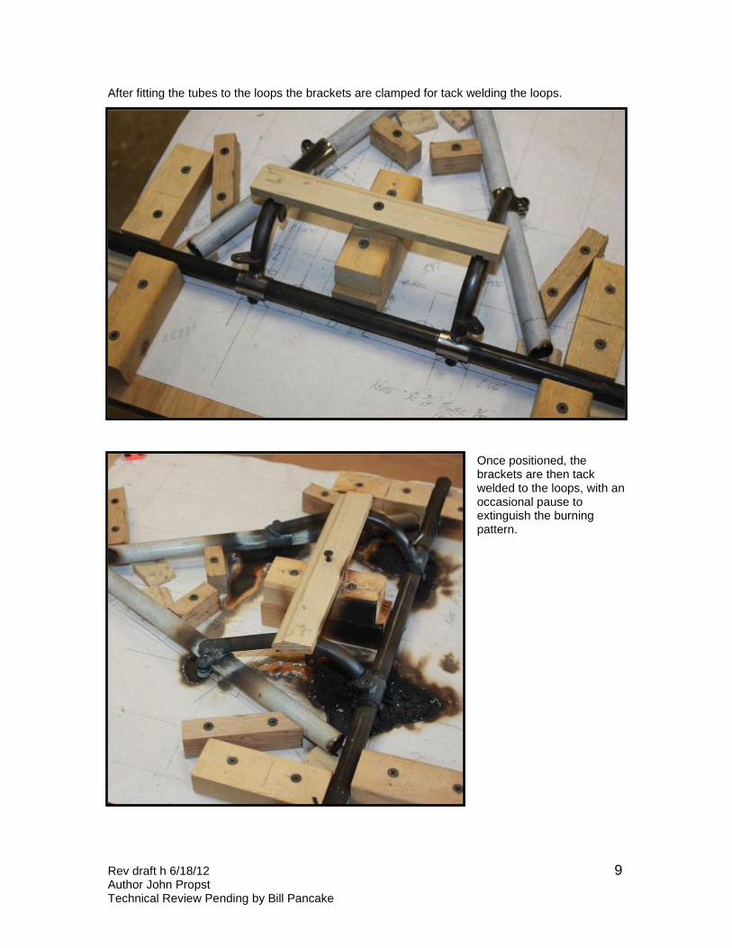
After fitting the tubes to the loops the brackets are clamped for tack welding the loops.
Once positioned, the brackets are then tack welded to the loops, with an occasional pause to extinguish the burning pattern.
Rev draft h 6/18/12 Author John Propst Technical Review Pending by Bill Pancake
10
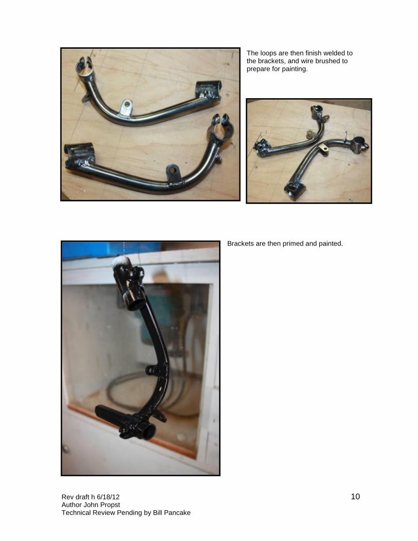
The loops are then finish welded to the brackets, and wire brushed to prepare for painting.
Brackets are then primed and painted.
Rev draft h 6/18/12 Author John Propst Technical Review Pending by Bill Pancake
11
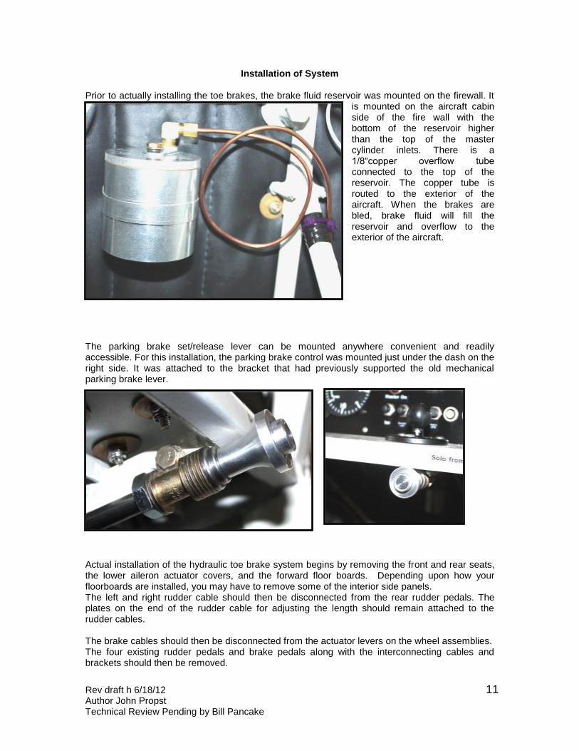
Installation of System Prior to actually installing the toe brakes, the brake fluid reservoir was mounted on the firewall. It
is mounted on the aircraft cabin side of the fire wall with the bottom of the reservoir higher than the top of the master cylinder inlets. There is a 1/8“copper overflow tube connected to the top of the reservoir. The copper tube is routed to the exterior of the aircraft. When the brakes are bled, brake fluid will fill the reservoir and overflow to the exterior of the aircraft.
The parking brake set/release lever can be mounted anywhere convenient and readily accessible. For this installation, the parking brake control was mounted just under the dash on the right side. It was attached to the bracket that had previously supported the old mechanical parking brake lever.
Actual installation of the hydraulic toe brake system begins by removing the front and rear seats, the lower aileron actuator covers, and the forward floor boards. Depending upon how your floorboards are installed, you may have to remove some of the interior side panels. The left and right rudder cable should then be disconnected from the rear rudder pedals. The plates on the end of the rudder cable for adjusting the length should remain attached to the rudder cables. The brake cables should then be disconnected from the actuator levers on the wheel assemblies. The four existing rudder pedals and brake pedals along with the interconnecting cables and brackets should then be removed.
Rev draft h 6/18/12 Author John Propst Technical Review Pending by Bill Pancake
12
This aircraft did not have a parking brake system. If your does, the complete mechanical parking brake system should be removed. The next step will be to remove the old mechanical drum brakes and install the new hydraulic calipers, brake drums, and wheels. For this installation, new tires and tubes were purchased and installed on the new wheels prior to the start of the project. If you choose to reuse your existing tires and tubes they will need to be removed from the old wheels and installed on the new wheels during the next step. Jacking up one side at a time, the existing wheels, bearings, and axle spacers are removed. The four AN4 bolts holding on the backing plate for the drum bakes are then removed. The hydraulic brake calipers are then mounted on the axle. The STC instructions indicate reusing the existing bolts and nuts, but new bolts and nuts should always be used. It is suggested that the caliper assembly be mounted on the aft side of the axle and rotated 45 degrees below horizontal. This is done so that the hydraulic brake tubing will be in line with the aft side of the axle. The STC provides no drawings or directions for running the hydraulic lines from the calipers to the parking brake so you will need to follow your I/A’s guidance for installing your hydraulic lines. After reviewing the parts provided in the kit and the drawings provide, it appeared that additional hydraulic lines or tubing would be needed to connect the calipers to the parking brake valve. The concern was reviewed by Wag-Aero’s technical staff and they provided two additional 21” flexible hoses for connecting the parking brake valve to the hydraulic lines going to the calipers. In the mean time the installation details and possible options for routing the hydraulic lines were reviewed with Bill Pancake. An enhanced method for installing the hydraulic system from the parking brake valve to the calipers was developed that would provide a clean transition of the hydraulic lines through the aircraft fabric. It should be noted that it would be perfectly acceptable to pass the hydraulic lines through holes in the fabric just as the mechanical cable had been installed, but we chose to use bulkhead fittings for a cleaner look. The following parts were ordered for hydraulic line bulkhead:
2 AN837-4D 45 degree bulkhead fittings 2 AN924-4D bulkhead fitting nuts 4 AN819-4D 1/4"aluminium tubing sleeves 4 AN818-4D 1/4" aluminum tubing nut 2 pieces of 1/4" aluminum tubing, about 18” each – cut length to fit 1 piece of .060” steel plate to fabricate bulkhead mounting plate 1 piece of .040” aluminum plate to fabricate bulkhead back plate – about 2” X 5”
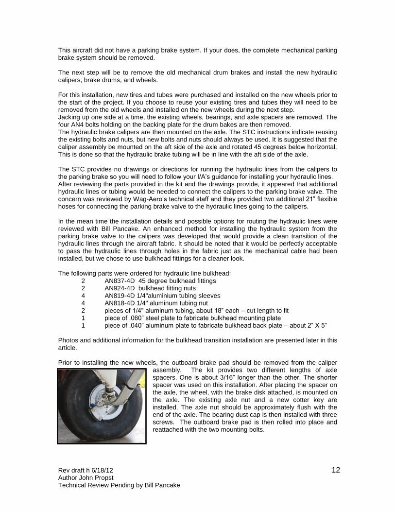
Photos and additional information for the bulkhead transition installation are presented later in this article. Prior to installing the new wheels, the outboard brake pad should be removed from the caliper
assembly. The kit provides two different lengths of axle spacers. One is about 3/16” longer than the other. The shorter spacer was used on this installation. After placing the spacer on the axle, the wheel, with the brake disk attached, is mounted on the axle. The existing axle nut and a new cotter key are installed. The axle nut should be approximately flush with the end of the axle. The bearing dust cap is then installed with three screws. The outboard brake pad is then rolled into place and reattached with the two mounting bolts.
Rev draft h 6/18/12 Author John Propst Technical Review Pending by Bill Pancake
13
The next step will be to install the master cylinder lower bracket that was modified with the tubing loops previously described in this article. Depending upon your aircraft, the lower engine cowling may or may not have to be removed. In the case of this installation, the lower engine cowling was not removed. The aircraft wrap around was opened to permit limited access to the area immediately behind the firewall. A couple boards were placed inside the cabin to provide support while crawling in and out of the cabin. Screwdrivers and pry-bars were used to gently open the space between the firewall and tube 45 which runs across the bottom of the firewall. The front and rear loops on the lower master cylinder support bracket are opened to permit fitting around the tubes. The brackets are placed on the front tube 45 near the center of the aircraft and then slide sideways into position. The loop ends are squeezed shut when they are in position. A brass drift is used to gently tap the front end of the lower support into position. Needle nosed pliers are used to position an elastic nut on the front side of the front loop and an AN 3 bolt is installed and loosely tightened. An AN 3 bolt is then installed at the aft end of the bracket and loosely tightened. The two bolts will be tightened after positioning and aligning the master cylinders. The new rudder pedals with toe brake actuators are then installed in accordance with Safe Air drawings. It is recommended that the toe brake pedals be fitted to the rudder pedals prior to installing. Most likely the toe brake pedals will need to be filed and adjusted to prevent binding and assure smooth operation. Also, the point where the master cylinder attaches to the toe pedal may need to be filed to assure a good fit. The drawings for assembling and installing the pedals are very good and detailed. After installing the new rudder pedals, brakes, and interconnecting bars, all bolts should be secured with cotter pins. Make sure there is no interference between the newly installed components and any of the existing aircraft components. The rudder pedals and toe brake pedals should operate smoothly without any binding. Install the new master cylinder to the lower support bracket. The position of the lower bracket should be adjusted sideways as needed so that the top end aligns with the attachment point on the toe brake pedal. After each master cylinder has been aligned, the clamp bolts on the lower bracket loops should be tightened. The rudder cables should now be reattached to the new rear rudder pedals just as they were removed from the old rudder pedals. After attaching the rudder cables, the existing large rudder pedal springs should be reinstalled on the rear rudder pedals and the existing small rudder pedal springs should be reinstalled on the front rudder pedals. The front end of the front spring is attached to the loop on the side of the master cylinder lower support bracket. This should complete the actual installation of the rudder pedals and the toe brake pedals. Again check and
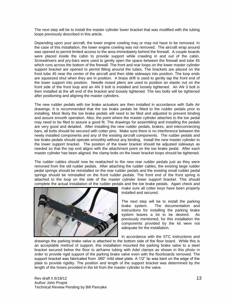
make sure all cotter keys have been properly installed and secured. The next step will be to install the parking brake system. The documentation and instructions for installing the parking brake system leaves a lot to be desired. As previously mentioned, for this installation the components provided by the kit were not adequate for the installation. In accordance with the STC instructions and
drawings the parking brake valve is attached to the bottom side of the floor board. While this is an acceptable method of support, this installation mounted the parking brake valve to a steel bracket secured below the floor to airframe tubing with Adel clamps as shown in this photo in order to provide rigid support of the parking brake valve even with the floorboards removed. The support bracket was fabricated from .060” mild steel plate. A 1/2” lip was bent on the edge of the plate to provide rigidity. The position and length of the support bracket was determined by the length of the hoses provided in the kit from the master cylinder to the valve.
Rev draft h 6/18/12 Author John Propst Technical Review Pending by Bill Pancake
14
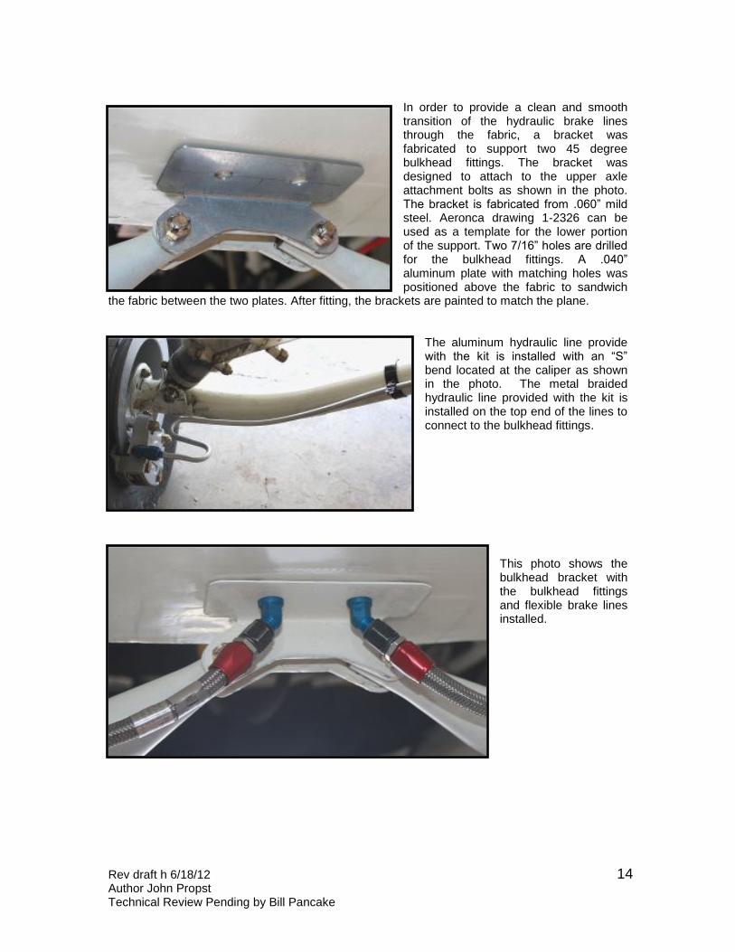
In order to provide a clean and smooth transition of the hydraulic brake lines through the fabric, a bracket was fabricated to support two 45 degree bulkhead fittings. The bracket was designed to attach to the upper axle attachment bolts as shown in the photo. The bracket is fabricated from .060” mild steel. Aeronca drawing 1-2326 can be used as a template for the lower portion of the support. Two 7/16” holes are drilled for the bulkhead fittings. A .040” aluminum plate with matching holes was positioned above the fabric to sandwich
the fabric between the two plates. After fitting, the brackets are painted to match the plane.
The aluminum hydraulic line provide with the kit is installed with an “S” bend located at the caliper as shown in the photo. The metal braided hydraulic line provided with the kit is installed on the top end of the lines to connect to the bulkhead fittings.
This photo shows the bulkhead bracket with the bulkhead fittings and flexible brake lines installed.
Rev draft h 6/18/12 Author John Propst Technical Review Pending by Bill Pancake
15
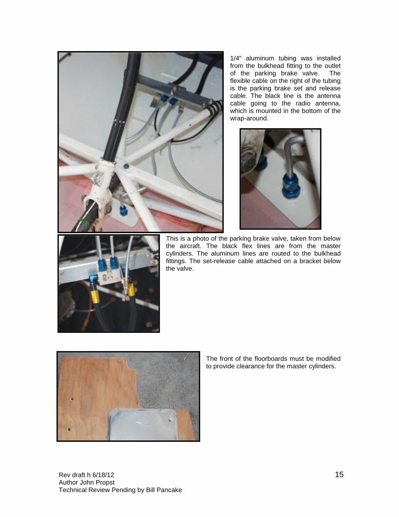
1/4" aluminum tubing was installed from the bulkhead fitting to the outlet of the parking brake valve. The flexible cable on the right of the tubing is the parking brake set and release cable. The black line is the antenna cable going to the radio antenna, which is mounted in the bottom of the wrap-around.
This is a photo of the parking brake valve, taken from below the aircraft. The black flex lines are from the master cylinders. The aluminum lines are routed to the bulkhead fittings. The set-release cable attached on a bracket below the valve.
The front of the floorboards must be modified to provide clearance for the master cylinders.
Rev draft h 6/18/12 Author John Propst Technical Review Pending by Bill Pancake
16
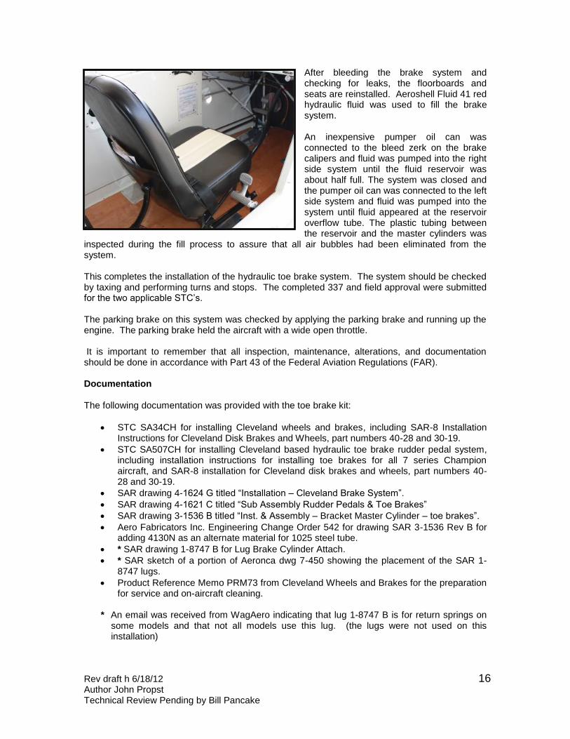
After bleeding the brake system and checking for leaks, the floorboards and seats are reinstalled. Aeroshell Fluid 41 red hydraulic fluid was used to fill the brake system. An inexpensive pumper oil can was connected to the bleed zerk on the brake calipers and fluid was pumped into the right side system until the fluid reservoir was about half full. The system was closed and the pumper oil can was connected to the left side system and fluid was pumped into the system until fluid appeared at the reservoir overflow tube. The plastic tubing between the reservoir and the master cylinders was
inspected during the fill process to assure that all air bubbles had been eliminated from the system. This completes the installation of the hydraulic toe brake system. The system should be checked by taxing and performing turns and stops. The completed 337 and field approval were submitted for the two applicable STC’s. The parking brake on this system was checked by applying the parking brake and running up the engine. The parking brake held the aircraft with a wide open throttle. It is important to remember that all inspection, maintenance, alterations, and documentation should be done in accordance with Part 43 of the Federal Aviation Regulations (FAR). Documentation The following documentation was provided with the toe brake kit:
STC SA34CH for installing Cleveland wheels and brakes, including SAR-8 Installation Instructions for Cleveland Disk Brakes and Wheels, part numbers 40-28 and 30-19.
STC SA507CH for installing Cleveland based hydraulic toe brake rudder pedal system, including installation instructions for installing toe brakes for all 7 series Champion aircraft, and SAR-8 installation for Cleveland disk brakes and wheels, part numbers 40-28 and 30-19.
SAR drawing 4-1624 G titled “Installation – Cleveland Brake System”.
SAR drawing 4-1621 C titled “Sub Assembly Rudder Pedals & Toe Brakes”
SAR drawing 3-1536 B titled “Inst. & Assembly – Bracket Master Cylinder – toe brakes”.
Aero Fabricators Inc. Engineering Change Order 542 for drawing SAR 3-1536 Rev B for adding 4130N as an alternate material for 1025 steel tube.
* SAR drawing 1-8747 B for Lug Brake Cylinder Attach.
* SAR sketch of a portion of Aeronca dwg 7-450 showing the placement of the SAR 1-8747 lugs.
Product Reference Memo PRM73 from Cleveland Wheels and Brakes for the preparation for service and on-aircraft cleaning.
* An email was received from WagAero indicating that lug 1-8747 B is for return springs on some models and that not all models use this lug. (the lugs were not used on this installation)
Rev draft h 6/18/12 Author John Propst Technical Review Pending by Bill Pancake
17
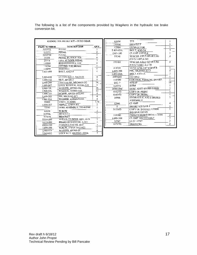
The following is a list of the components provided by WagAero in the hydraulic toe brake conversion kit.
Rev draft h 6/18/12 Author John Propst Technical Review Pending by Bill Pancake
18
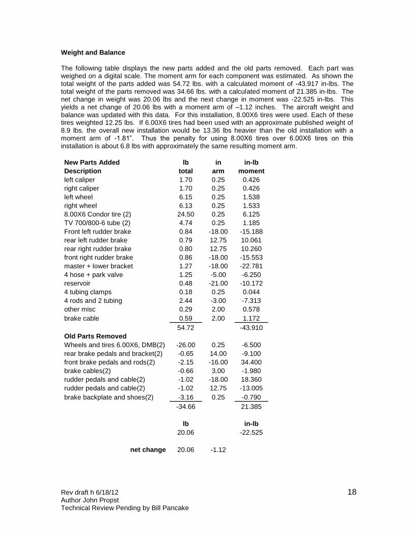
Weight and Balance The following table displays the new parts added and the old parts removed. Each part was weighed on a digital scale. The moment arm for each component was estimated. As shown the total weight of the parts added was 54.72 lbs. with a calculated moment of -43.917 in-lbs. The total weight of the parts removed was 34.66 lbs. with a calculated moment of 21.385 in-lbs. The net change in weight was 20.06 lbs and the next change in moment was -22.525 in-lbs. This yields a net change of 20.06 lbs with a moment arm of –1.12 inches. The aircraft weight and balance was updated with this data. For this installation, 8.00X6 tires were used. Each of these tires weighted 12.25 lbs. If 6.00X6 tires had been used with an approximate published weight of 8.9 lbs. the overall new installation would be 13.36 lbs heavier than the old installation with a moment arm of -1.81”. Thus the penalty for using 8.00X6 tires over 6.00X6 tires on this installation is about 6.8 lbs with approximately the same resulting moment arm.
New Parts Added lb in in-lb
Description total arm moment
left caliper 1.70 0.25 0.426
right caliper 1.70 0.25 0.426
left wheel 6.15 0.25 1.538
right wheel 6.13 0.25 1.533
8.00X6 Condor tire (2) 24.50 0.25 6.125
TV 700/800-6 tube (2) 4.74 0.25 1.185
Front left rudder brake 0.84 -18.00 -15.188
rear left rudder brake 0.79 12.75 10.061
rear right rudder brake 0.80 12.75 10.260
front right rudder brake 0.86 -18.00 -15.553
master + lower bracket 1.27 -18.00 -22.781
4 hose + park valve 1.25 -5.00 -6.250
reservoir 0.48 -21.00 -10.172
4 tubing clamps 0.18 0.25 0.044
4 rods and 2 tubing 2.44 -3.00 -7.313
other misc 0.29 2.00 0.578
brake cable 0.59 2.00 1.172
54.72 -43.910
Old Parts Removed
Wheels and tires 6.00X6, DMB(2) -26.00 0.25 -6.500
rear brake pedals and bracket(2) -0.65 14.00 -9.100
front brake pedals and rods(2) -2.15 -16.00 34.400
brake cables(2) -0.66 3.00 -1.980
rudder pedals and cable(2) -1.02 -18.00 18.360
rudder pedals and cable(2) -1.02 12.75 -13.005
brake backplate and shoes(2) -3.16 0.25 -0.790
-34.66 21.385
lb in-lb
20.06 -22.525
net change 20.06 -1.12