Embed Size (px)
Citation preview
rspa.royalsocietypublishing.org
ReviewCite this article: Shyy W, Kang C-k,Chirarattananon P, Ravi S, Liu H. 2016Aerodynamics, sensing and control ofinsect-scale flapping-wing flight. Proc. R.Soc. A 472: 20150712.http://dx.doi.org/10.1098/rspa.2015.0712
Received: 15 October 2015Accepted: 4 January 2016
Subject Areas:biomechanics
Keywords:biomimicry, flapping flight, insect scale
Author for correspondence:Wei Shyye-mail: [email protected]
Aerodynamics, sensingand control of insect-scaleflapping-wing flightWei Shyy1, Chang-kwon Kang2,
Pakpong Chirarattananon3, Sridhar Ravi4,5
and Hao Liu5,6
1Department of Mechanical and Aerospace Engineering, Hong KongUniversity of Science and Technology, Clear Water Bay, Hong Kong2Department of Mechanical and Aerospace Engineering,University of Alabama in Huntsville, Huntsville, AL, USA3Department of Mechanical and Biomedical Engineering,City University of Hong Kong, Kowloon Tong, Hong Kong4Graduate School of Engineering, Chiba University, Chiba, Japan5School of Aerospace, Mechanical and Manufacturing Engineering,RMIT University, Melbourne, Victoria, Australia6Shanghai-Jiao Tong University and Chiba University InternationalCooperative Research Centre (SJTU-CU ICRC), Minhang,Shanghai, China
There are nearly a million known species offlying insects and 13 000 species of flying warm-blooded vertebrates, including mammals, birds andbats. While in flight, their wings not only moveforward relative to the air, they also flap up anddown, plunge and sweep, so that both lift andthrust can be generated and balanced, accommodateuncertain surrounding environment, with superiorflight stability and dynamics with highly variedspeeds and missions. As the size of a flyer is reduced,the wing-to-body mass ratio tends to decrease aswell. Furthermore, these flyers use integrated systemconsisting of wings to generate aerodynamic forces,muscles to move the wings, and sensing and controlsystems to guide and manoeuvre. In this article, recentadvances in insect-scale flapping-wing aerodynamics,flexible wing structures, unsteady flight environment,sensing, stability and control are reviewed withperspective offered. In particular, the special featuresof the low Reynolds number flyers associated withsmall sizes, thin and light structures, slow flight
2016 The Author(s) Published by the Royal Society. All rights reserved.
on May 30, 2018http://rspa.royalsocietypublishing.org/Downloaded from on May 30, 2018http://rspa.royalsocietypublishing.org/Downloaded from on May 30, 2018http://rspa.royalsocietypublishing.org/Downloaded from
2
rspa.royalsocietypublishing.orgProc.R.Soc.A472:20150712
...................................................
with comparable wind gust speeds, bioinspired fabrication of wing structures, neuron-basedsensing and adaptive control are highlighted.
1. IntroductionThere are nearly a million species of flying insects. Of the non-insects, another 13 000 warm-blooded vertebrate species, including mammals, about 9000 birds and 1000 bats, have taken tothe skies [1]. In parallel, human-engineered flapping-wing-based micro air vehicles (MAVs) havebeen actively investigated in the last two decades or so, and can revolutionize our capabilities inareas such as environmental monitoring and surveillance and security. Compared to flappingwings, conventional aeroplanes with fixed wings are relatively simple. The forward motionrelative to the air causes the wings to generate lift, with the thrust being produced by theengine. In biological flight, the wings not only move forward relative to the air, they alsoflap up and down, plunge and sweep [2–5], so that both lift and thrust can be generated andbalanced in accordance with the instantaneous flight task. By increasing the wing speed relativeto the air while adjusting the effective angle of attack (AoA), natural flyers generate sufficientlift, accommodate uncertain surrounding environment and offer superior flight stability anddynamics with highly varied speeds and missions.
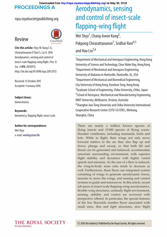
As the size of a flyer is reduced, the wing-to-body mass ratio tends to decrease as well.Figure 1 illustrates such a trend and some of the major implications via the relationship betweenthe Reynolds number and wingbeat frequency. The Reynolds number, defined as Re = UrefL/v,where Uref and L are the characteristic velocity and length scales, respectively, and v is thekinematic viscosity of air and is an important dimensionless number in aerodynamics; it providesan indication of the relative magnitudes of the flow inertia and viscous effects [6]. The wings oflarge birds such as ospreys, kites and eagles account for 20% or more of their body weight. Asthe size of the flyer is reduced, the Reynolds number and the wing/body mass ratio decrease ingeneral, while the flapping frequency increases.
Those with a higher wing-to-body mass ratio and moment of inertia, such as bats andbutterflies, are more manoeuvrable, capable of making abrupt changes of trajectories within atime comparable to that of a flapping cycle. Their larger inertia make the flyers capable of makingturns within one or two flapping periods. However, they pay a penalty for this ability because aheavier wing consumes more energy while flapping. With the flapping and body response timescales being comparable, the flyer’s flight dynamics and control need to be closely linked to theinstantaneous aerodynamics, because the time history of the flapping-wing aerodynamics directlyaffects a flyer’s performance characteristics.
Many small flyers with lower wing-to-body mass ratio, such as hummingbirds and insects(with butterflies as a notable exception), tend to have much faster flapping time scales than theirbodies’ response time scale. The lift, drag and thrust variations during the flapping cycle tendto be smoothed out over the entire flight flapping cycles. However, this does not mean that theflapping-wing aerodynamics of small flyers can simply be considered as quasi-steady.
In this article, recent advances in flapping-wing aerodynamics, flexible wing structures,unsteady flight environment, sensing, stability and control associated with flapping-wing flight,focusing on insect-scale issues, are reviewed with perspective offered.
2. Key scaling parameters of flapping wing aerodynamicsScaling laws are useful to reduce the number of parameters, to clearly identify characteristicproperties of the system under consideration and to indicate which combination of parametersbecomes important under a given condition [7–9]. In flapping-wing flight, three-dimensionlessparameters (table 1) are often used to relate the fluid dynamics and wing kinematics to
on May 30, 2018http://rspa.royalsocietypublishing.org/Downloaded from
3
rspa.royalsocietypublishing.orgProc.R.Soc.A472:20150712
...................................................
wing beat frequency
Rey
nold
s nu
mbe
r
avian scale
— high wing inertia
— large active shape deformation
— sensing and actuation distributed on wing
— O(flapping timescales) ~ O(vehicle timescales)
insect scale
— low wing inertia - fast response
— actuation at wing hinge
— shape deformation for passive control
— O(flapping timescales) < O(vehicle timescales)
wing/body mass ratio ~10–20%
wing/body mass ratio ~1–5%
Figure 1. Characteristics of biological flapping flight based on the Reynolds number, flapping frequency and wing/body massratio.
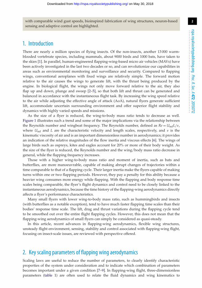
(a) (b) (c)
Figure 2. Numerical results of LEV structures at different Reynolds numbers. Adapted from [10]. (a) Hawkmoth, Re= 6000,(b) fruit fly, Re= 120 and (c) thrips, Re= 10.
Table 1. Dimensionless parameters in a flapping-wing system.
dimensionless parameter symbol definition
Reynolds number Re UrefL/v. . . . . . . . . . . . . . . . . . . . . . . . . . . . . . . . . . . . . . . . . . . . . . . . . . . . . . . . . . . . . . . . . . . . . . . . . . . . . . . . . . . . . . . . . . . . . . . . . . . . . . . . . . . . . . . . . . . . . . . . . . . . . . . . . . . . . . . . . . . . . . . . . . . . . . . . . . . . . . . . . . . . . . . . . . . . . . . . . . . . . . . . . . . . . . . . . . . . . . . . . .
reduced frequency k fL/Uref. . . . . . . . . . . . . . . . . . . . . . . . . . . . . . . . . . . . . . . . . . . . . . . . . . . . . . . . . . . . . . . . . . . . . . . . . . . . . . . . . . . . . . . . . . . . . . . . . . . . . . . . . . . . . . . . . . . . . . . . . . . . . . . . . . . . . . . . . . . . . . . . . . . . . . . . . . . . . . . . . . . . . . . . . . . . . . . . . . . . . . . . . . . . . . . . . . . . . . . . . .
Strouhal number St 2fha/Uref. . . . . . . . . . . . . . . . . . . . . . . . . . . . . . . . . . . . . . . . . . . . . . . . . . . . . . . . . . . . . . . . . . . . . . . . . . . . . . . . . . . . . . . . . . . . . . . . . . . . . . . . . . . . . . . . . . . . . . . . . . . . . . . . . . . . . . . . . . . . . . . . . . . . . . . . . . . . . . . . . . . . . . . . . . . . . . . . . . . . . . . . . . . . . . . . . . . . . . . . . .
the resulting force coefficients. Other dimensionless parameters relevant to the fluid–structureinteraction are highlighted in §4c.
Most insects and birds fly in the Reynolds number regime between O(101) and O(104). Atthese low Reynolds numbers, both viscous and inertia effects are important and the flow ischaracterized by unsteady large vortical flow structures. The structure and stability of largecoherent vortices, forming a well-identified lower pressure core to help enhance lift, are highlyinfluenced by the Reynolds number [10,11]. At the hawkmoth scale of Re = 6000, the leading-edge
on May 30, 2018http://rspa.royalsocietypublishing.org/Downloaded from

4
rspa.royalsocietypublishing.orgProc.R.Soc.A472:20150712
...................................................
vortex (LEV), the large vortical structure near the leading-edge of the wing, is intense, conical withsignificant spanwise flow at the core, and breaks down at 75% of the span (figure 2a). At Re = 120,relevant for fruit flies, the LEV is connected to the wing tip vortex (TiV) and the spanwise flowis weaker (figure 2b). At the thrips scale of Re = 10, the LEV is cylindrical and uniform along thewing span (figure 2c).
The reduced frequency k is a measure of unsteadiness that compares the spatial wavelength ofthe flow disturbance to the chord [12]; it gives the ratio between the fluid convection time scale,L/Uref, and the motion time scale, 1/f , where f is the flapping frequency. In forward flight, thereduced frequency and the wingbeat amplitude tend to be low, between 0.1 and 0.3 [1].
The Strouhal number indicates the ratio between the reference velocity and flapping speedbased on the peak-to-peak amplitude. It characterizes the dynamics of the wake and sheddingbehaviour of vortices of a flapping wing in forward flight [12,13]. For a family of two-dimensionalwakes of oscillating foils in water [14], the Strouhal number range between 0.25 < St < 0.35 wasfound to be efficient [13,15,16]. Moreover, insects, birds and bats flap their wings in a similarrange 0.2 < St < 0.4 in forward flight [17]. The Strouhal number is also associated with the optimalvortex formation in biological propulsion [18].
3. Rigid flapping-wing aerodynamics
(a) Unsteady lift enhancement mechanismsNatural flyers use flapping mechanisms to generate lift and thrust. These mechanisms are relatedto formation and shedding of the vortices into the flow, varied wing shape and structuralflexibility [1].
The earliest unsteady lift generation mechanism to explain how insects fly, found by Weis-Fogh[19], was the clap-and-fling motion of a chalcid wasp, Encarsia formosa. The relative benefit of clap-and-fling lift enhancement strongly depended on stroke kinematics and could potentially increasethe performance by reducing the power requirements [20,21]. The clap-and-fling mechanism isbeneficial in producing a mean lift coefficient to keep a low weight flyer aloft. Numerous naturalflyers, such as hawkmoths, butterflies, fruit flies, wasps and thrips enhance their aerodynamicforce production with the clap-and-fling mechanism [19,22–25].
At the end of each stroke, flapping wings often experience rapid pitching rotation, which canenhance the aerodynamic force generation [26]. The phase difference between the translation andthe rotation can be used as a lift controlling parameter. Similar to the Magnus effect, if the wingflips before a stroke ends, then the wing undergoes rapid pitch-up rotation in the favourabletranslational direction enhancing the lift. This is called the advanced rotation. On the other hand,in delayed rotations, if a wing rotates back after the stroke reversal, then when the wing startsto accelerate, it pitches down resulting in reduced lift [26]. The lift peak at the stroke ends wasshown to be proportional to the angular velocity of the wing using the quasi-steady theory [27].
The wake capture mechanism is often observed during a wing–wake interaction. When thewings reverse their translational direction, the wings meet the wake created during the previousstroke, by which the effective flow velocity increases and additional aerodynamic force peak isgenerated [1,26,28–32]. The effectiveness of the wake capture mechanism is also a function ofwing kinematics and flow structures around the flapping wings.
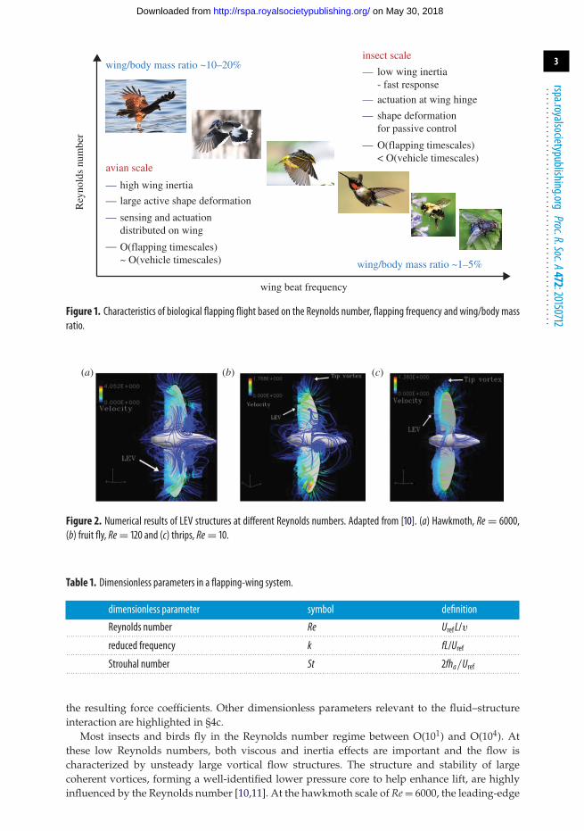
The delayed stall of LEV can significantly promote lift associated with a flapping wing [33–35].The LEV creates a region of lower pressure above the wing and hence it would enhance lift. Whena flapping wing travels several chord lengths, the flow separates from the leading and trailingedges, as well as at the wing tip, and forms large organized vortices known as a LEV, a trailingedge vortex, and a TiV (figure 3). In hover, however, depending on the specific kinematics, theTiVs could either promote or make little impact on the aerodynamics of a low aspect ratio flappingwing [32]. As detailed in Shyy et al. [1,36], for Re = O(102), corresponding to the small insect flightregime, investigations of the aerodynamic performances associated with various wing geometryand flapping kinematics showed that there is significant variance in the spanwise distribution
on May 30, 2018http://rspa.royalsocietypublishing.org/Downloaded from
5
rspa.royalsocietypublishing.orgProc.R.Soc.A472:20150712
...................................................
LEV
TEV
TiV
Figure 3. Vortical flow structures around a low aspect ratio flapping wing. Spanwise vorticity iso-surfaces are coloured by thevorticity magnitude. Streamlines are coloured with the horizontal velocity magnitude.
of forces for three-dimensional wings. Wing motions with a prominent TiV exhibit significantvariations along the span. Furthermore, kinematics with low angles of attack that suppress theTiV generation, appear to have a relatively constant response along the span. According to theclassical stationary wing theory [37], a three-dimensional low aspect ratio wing experiences alower lift than its two-dimensional counterpart due to the downwash associated with TiVs.In unsteady flow around a hovering wing, however, the TiVs can contribute to lift generationrather than just drag generation on the wing [31].
The LEV is common and important to the flapping-wing aerodynamics at the Reynoldsnumber of O (104) or lower, which corresponds to the hummingbird and insect flight regimes.However, the LEV structures and distribution of spanwise flow inside the LEV change with thevariation of Reynolds number (wing sizing, flapping frequency, etc.) and with the interactionsbetween LEVs and TiVs and hence influence the aerodynamic force generation, see also §2. Thestability of the prolonged attachment of the LEV on the wing is also related to the convectionof momentum along the spanwise direction [11]. The LEV as a lift enhancement mechanism forflapping wing at Reynolds number of O (105–106) seem less certain because, as pointed out in [38],a dynamic-stall vortex on an oscillating aerofoil is often found to break away and to convectelsewhere as soon as the aerofoil translates. More comprehensive review of the unsteady liftenhancement mechanisms can be found in [1,30,39].
(b) Tandem and corrugated wingsFor many insects, four winged with two pairs of fore and hindwings are observed and wing–wing interactions play an important role in aerodynamics and stability. In Lepidoptera, whichincludes butterflies and moths, the fore and hindwings usually flap in sync. For some moths,the fore and hindwings are even mechanically coupled [40], whereas butterflies can controlthe wings individually [41]. Butterflies are known to be anteromotoric, driven primarily byforewings [42]. Most studies of Lepidoptera analyse their wings as a whole, instead of analysingfore and hindwings separately and the effects of the wing–wing interaction for butterflies are stillnot well understood.
Dragonflies also have two pairs of fore and hindwings with relatively high aspect ratio. Theycan glide, flap and hover while showcasing amazing manoeuvring abilities. Dragonflies are oneof the fastest insects with good manoeuvrability [43]. The phase difference between the foreand hindwing motions is known to be one of the keys of dragonflies’ flight characteristics. Byoptimizing wing–wing interaction, dragonflies can enhance the aerodynamic efficiency [43,44]and improve gust resistance [43]. For example, while cruising, dragonflies’ fore and hindwings are
on May 30, 2018http://rspa.royalsocietypublishing.org/Downloaded from
6
rspa.royalsocietypublishing.orgProc.R.Soc.A472:20150712
...................................................
out of phase to attain better flight efficiencies [45]. The interaction between the fore and hindwingsis highly affected by the wake structures produced by both wings [46]; while the wing–vortexinteraction can lead to increased lift and thrust [43,47], it can also be detrimental to lift due todownwash [48,49]. The flapping motions are in reduced phase shift to generate large magnitudeforces and accelerations during manoeuvres [50–52]. One major deficiency of the literature todate is that the wings are considered to be rigid wings and smooth without accounting for theintrinsic structural flexibility and corrugation [53]. Both structural flexibility and corrugation cansubstantially affect the nearwing wake structure and resulting aerodynamic forces [1].
Another issue is the connection between the wing phasing and the effective wing aspectratio. For example, the dragonfly, Sympetrum sanguineum [54], has an aspect ratio of 9.54 for itsforewing and 6.94 for its hindwing. When the wings operate in close proximity, functioningas one low aspect ratio wing while neglecting the gap between the fore and hindwings, theaspect ratio changes to 4.18, which is less than half of the aspect ratio of the forewing. For out ofphase flapping, they operate with two pairs of high aspect ratio wings, which interact with eachother to produce a more complex flow phenomenon and harvest additional energy by removingexcess swirl from the wake [44,55]. On the other hand, in the case of in phase flapping, whendragonflies execute high energy demand flight manoeuvres or take-off [51], the wings operatein close proximity, which essentially can be considered as one low aspect ratio wing. The flowstructures associated with these different flapping modes are highlighted by Fu et al. [55].
While conventional aerofoils are smooth and streamlined, insect wings exhibit rough surfaces,e.g. the cross-sectional corrugations of dragonfly wings or scales on the wing surface ofbutterfly and moth. It is suggested that corrugated wing configuration can help the aerodynamicperformance and stability of the wing’s ultralight construction [1,43,56–64]. However, the detailedphysical mechanisms accounting for a corrugated wing’s influence on its aerodynamics is stillto be further investigated [57]. The conventional view is that vortices fill the profile valleysformed by these bends and therefore smooth the profile geometry [59]; other investigations[43,60,61] suggest that a smooth rigid flat plate may aerodynamically perform better than acorrugated wing.
(c) Quasi-steady models of flapping-wing aerodynamicsEarly analyses in flapping-wing aerodynamics have used actuator disc models from helicoptertheories to estimate lift on insect wings [65] based on the parallels that exist between flappingwing and rotary wing flight. Both use a self-generated wing motion to create lift. Both tilt thestroke/rotational planes forward in order to generate propulsive forces. However, the directapplication of helicopter theory in flapping-wing aerodynamics ignores the essential feature offlapping as a reciprocating and intermittent lifting and propulsion mechanism, in which thegenerated forces result from an unsteady momentum flux [66].
To model the lift and drag as a function of time for flapping wings, unsteady linearized theoriesand quasi-steady models for pitching and plunging aerofoils [67–69] are often applied to insectflapping-wing aerodynamics. Since the associated flow is unsteady, a quasi-steady model basedon the nominal position and angles of a wing relative to undisturbed freestream does not capturethe main physics properly. An adjusted quasi-steady model by correcting the surrounding flowparameters including the effective AoA and associated flow structures such as jet flows, canperform much better. By assuming that the instantaneous aerodynamic forces depend on theinstantaneous velocity and acceleration of the wing motion, these quasi-steady models provide aclosed form formulation for the delayed stall, rotational circulation and added mass [26,27,70,71]including passively rotating wings [72] and chordwise flexible aerofoils [73].
A quasi-steady model can be valuable if a proper account can be given to address the effects ofwing kinematics on the delayed stall and other unsteady mechanisms [26]. Such an approachoften under-represent, for example, the influence from the nonlinear wing–wake interactionrelevant in certain cases [26,74]. A fundamental limitation of these simplified models is the lack ofinformation of the key physical parameters, such as the lift coefficient as a function of AoA while
on May 30, 2018http://rspa.royalsocietypublishing.org/Downloaded from
7
rspa.royalsocietypublishing.orgProc.R.Soc.A472:20150712
...................................................
25 120
80
40
0
–40
–80
20
15
10
5
0
0 0.2 0.4 0.6stroke cycle
vert
ical
for
ce (
mN
)
pow
er (
mW
)
stroke cycle0.8 1.0 0 0.2 0.4 0.6 0.8 1.0
–5
(a) (b)
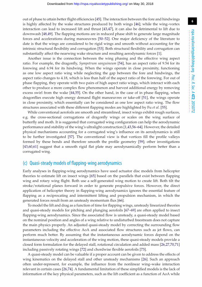
Figure 4. Comparison of (a) aerodynamic lift and (b) power. Navier–Stokes informed hybrid quasi-steady model (blue);Navier–Stokes equation solution (red). Adapted from [78].
the wing undergoes unsteady motions [26] and aerodynamic [75] or aeroelastic [73] dampingcoefficients. These coefficients are empirically determined from various experiments [26,27,73,76].Such a need for empirically fitted coefficients can be partially mitigated by considering anunsteady model that captures the nonlinear effect of the LEV on the lift [77] or a hybridmodel of high-fidelity Navier–Stokes equation solutions and low-order quasi-steady models [78].Nevertheless, it is important that a first principle-based framework be established. By fittingthe coefficients in the quasi-steady models to the solutions from the high-fidelity Navier–Stokesequations, an efficient yet accurate solution can be obtained even for a complex three-dimensionalflapping-wing motion as illustrated in figure 4.
4. Aeroelastic wing dynamicsBirds, bats and insects flex their wings to change the wing shape and area during flight eitheractively or passively. Since the aerodynamic force depends on the wing area, an increase in theprojected area due to wing deformation can lead to a performance enhancement [36]. On the otherhand, bat wings are made of a thin membrane supported by the arm and finger bones. Due to thestretchiness, bats wing membranes can deform only marginally, reducing the span by about 20%.When the forward speed exceeds a critical value, the flexible wings can spontaneously start toflap, enhancing the lift due to an attached LEV during the downstroke [79], accompanied by ahigher drag. However, over-flexing wings can lead to inefficient aerodynamic performance [1].
Insect wings, much smaller and thinner than bird and bat wings, can substantially deformduring flight due to the structural flexibility instead of active manipulation. Their wing propertiesare anisotropic because of the membrane–vein structures [1]. The wing thickness varies acrossspan and chord. Moreover, the wing motion is three-dimensional with a wing rotation at thewing root. The spanwise bending stiffness is about 1 to 2 orders of magnitude larger thanthe chordwise bending stiffness in a majority of insect species [80,81]. They exhibit substantialvariations in aspect ratios and shapes, but share a common feature of a reinforced leadingedge [81]. A dragonfly wing has more local variations in its structural composition and is morecorrugated than the wing of a cicada or a wasp. The wing corrugation increases both warpingrigidity and flexibility [82]; however, its aerodynamic effects are still not well understood [43].Furthermore, studies of neuromuscular control indicate that flies can actively modulate strokedeviation by altering the activity of steering muscles [83,84]. While normal hovering with anearly flat plane strokes are observed [19], most insects often exhibit U-shaped [85,86] or figureof eight motions [26,87]. The complex interplay between the kinematics of the wing, anisotropicwing structures and nonlinear unsteady aerodynamics makes the analysis of flapping-wing flyersextremely challenging, but also intriguing.
on May 30, 2018http://rspa.royalsocietypublishing.org/Downloaded from
8
rspa.royalsocietypublishing.orgProc.R.Soc.A472:20150712
...................................................
wing span (m)
span
wis
e E
I (N
m2 )
Odonata
Menoptera
Diptera
Lepidoptera
IsopteraNeuroptera
AeshnaPachydiplaxLestesIschnuraZootermopsisHemerobiusPepsisSceliphronBombusTipulaVillaEristalisCalliphoraManducaOchlodesPieris
glass slide
10–3
10–4
10–5
10–6
10–7
10–8
0.005 0.01 0.1
artificial wings
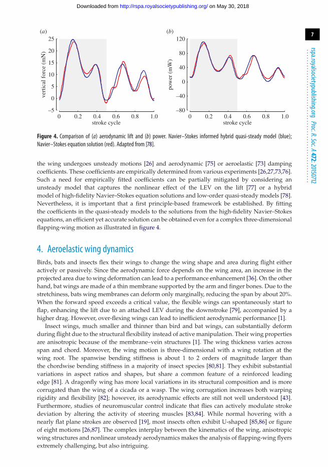
Figure 5. Spanwise flexural stiffness of various insect species versus wingspan from [80], overlaid by flexural stiffness offabricated wings from [95–100]. Adapted from [80].
(a) Flexible wing designBiological data and physics of scaling provide researchers with preliminary morphologicalparameters regarding the appropriate wing size, flapping frequency, and flight speed basedon the projected size and weight of the vehicles [1,88]. The scaling of wing length followsfrom the concept of wing loading, the ratio of wing area over weight, which is determined bybalancing of weight and lift in steady flight [1,89]. Based on mass and wingspan data from[89,90] covering a wide range of flying animals and machines, Liu suggests that, over a largerange of the weight, the wing length of birds and aircraft basically follows the power lawm ∝ R1/3 [91]. The proposed scaling law is consistent with the wingspan data [92] of flapping-wing insects, hummingbirds and robots at the small end of the spectrum. The best fit line across25 species and five flight-capable robots is given as R ∝ m0.36. Similar physical arguments couldbe made regarding the flapping frequency. By considering the limit of muscle power, Pennycuick[93] bounds the maximum flapping frequency as fmax ∝ m−1/3, whereas Shyy et al. [1] predictsthe lower bound of flapping frequency from the lift requirement as fmin ∝ m−1/6. Again, thepredictions are in accordant with insects, hummingbirds and small flapping-wing robot data from[92] that indicates f ∝ m−0.22.
In addition to shape and size, aerodynamic performance of flying insects is highly dependenton deformation of the wings during flight. Owing to the absence of muscles at wing base,deformation of the insect wings in flight is primarily due to the couple between aerodynamicforces, wing structure and inertial [80,94]. Biological studies on multiple insect species reveal astrong correlation between wing flexibility (in both spanwise and chordwise directions, with thespanwise stiffness being 1–2 orders of magnitude larger than chordwise stiffness) and wingspan(figure 5) [80]. This indicates that shape, material density and wing flexibility are critical toaerodynamic performance. This information supplies researchers with basic design parametersfor fabrication of artificial flapping wings.
Driven by the availability of examples from biology and the lack of comprehensiveunderstanding of flapping-wing aerodynamics and aeroelasticity, a common approach in thedesign of artificial wings is to take inspiration from nature. Numerous fabricated wings wereshaped after biological fliers, including ravens [101], bats [95], hawkmoths [102], dragonflies[88,103], butterflies [88], flies [104], hoverflies [96,105] and cicadas [106]. Simultaneously, veingeometry, wingframe and membrane materials are required to possess appropriate strength andstiffness. In one of the pioneering flapping-wing MAV prototypes [88], the authors mimicked the
on May 30, 2018http://rspa.royalsocietypublishing.org/Downloaded from
9
rspa.royalsocietypublishing.orgProc.R.Soc.A472:20150712
...................................................
wing design based on bat wings. Titanium alloy was chosen as material for the wingframe thanksto its ductile property and compatibility with the manufacturing process. Silicon was found tobe too fragile and unable to withstand flapping motion as fast as 30 Hz and the high density ofstainless steel rendered in unsuitable for the application.
In other flapping-wing devices, it is not uncommon to customize materials and wing geometryof fabricated wings to obtain desired physical properties [97,102]. Meng et al. [97] chose 40-µm-thick SU-8 as the material for the veins and the 7.5 µm thick polyimide as wing membranefor a 3.5 cm wingspan prototype. The resultant wings have the flexural stiffness comparableto dipteran insects [97]. Agrawal et al. [102] performed an extensive analysis on aerodynamicperformance and wing deformation of synthetic hawkmoth wings constructed from differentmaterials (carbon, nylon and rubber). Therein, the leading edge and trailing edge veins wereoptimized to achieve the desired deformation profile. A plot summarizing and comparing thespanwise stiffness of artificial wings and insect wings of various sizes is illustrated in figure 5.
With potential benefits to the aerodynamic performance [59], more recently, some researchershave explored three-dimensional wing designs with cambered and corrugated structures [96,98,99]. In [96], hoverfly-like wing was designed and fabricated with 50–125 µm vein heightsand 100 µm corrugation heights. The combination of veins and corrugations affects the wingdeformation under different loading that are believed to play a role in lift and drag coefficientsat low Reynolds number conditions [107]. Bioinspired wings in [99] were designed to featuremicroscale wrinkles similar to bird feathers. Compared to a flat counterpart, the produced winghas an increased flexural stiffness and reduced tensile stiffness. The incorporation of chordwiseunidirectional wrinkles allows fine tuning of stiffness and was experimentally found to produce20% greater aerodynamic lift in a tethered flapping test.
(b) Wing fabricationAs mentioned, the aerodynamic performance of flapping wings is essentially determined byrelevant physical properties such as density and flexural stiffness. This subsequently influencesmaterial choices and the compatible wing fabrication process. In bird-sized flapping-wingrobots, researchers are less restricted on the materials and manufacturing methods. Carbonrods are the most prevalent option for constructing structural components due to its favourablestiffness-to-weight ratio [102,108–111]. Metal sheets, latex, PVC film and nylon have beenexperimentally employed as wing membrane [111,112]. At bird scale, artificial wings are typicallyconstructed via a traditional simple cut-and-glue method. That is, the wingframes are bonded tothe membrane using epoxy or cyanoacrylate adhesive [102,111].
The cut-and-glue approach benefits from simplicity and affordability. As the size scalereduces, the polyester film, Mylar, becomes a popular membrane material owing to itsstrength [105,108,110,113]. In the meantime, precision in the manufacturing process becomesincreasingly important to obtain reliable results. In many cases, simple alignment mechanismsare incorporated the assembly process to improve accuracy and repeatability of the fabricatedwings [99,109,110].
A paper mould was introduced in [110] for bonding carbon rods to 15 µm Mylar film in thefabrication of a flight-capable flapping-wing device with a wingspan of 22 cm. In the fabricationprocess of 14 g device with 28 cm wingspan, DelFly II, a CNC machine, was used to mill the wingcontours into a wooden plate. When placed on a vacuum table, the Mylar is sucked onto the plate,enabling the carbon leading edges and stiffeners to be glued using cyanoacrylate adhesive at highprecision [103,113].
For wing fabrication for insect-sized devices, researchers need to overcome miniaturizationchallenges since conventional macroscale fabrication methods do not provide adequate precisionand repeatability, while other conventional technologies for silicon-based microelectromechanicalsystems (MEMS) are traditionally for manufacturing devices at smaller size scales [88,105]. As aresult, the MEMS-based wing fabrication technique was pioneered by Pornsin-sirirak et al. for apalm-sized Microbat robot that demonstrated successful free flight [88,95]. In the corresponding
on May 30, 2018http://rspa.royalsocietypublishing.org/Downloaded from
10
rspa.royalsocietypublishing.orgProc.R.Soc.A472:20150712
...................................................
adhesive layer
membrane layer
structure layer
finallaser micromachininglaminate
pre-machined layers
releasedwings
(b)
(a)
(c)
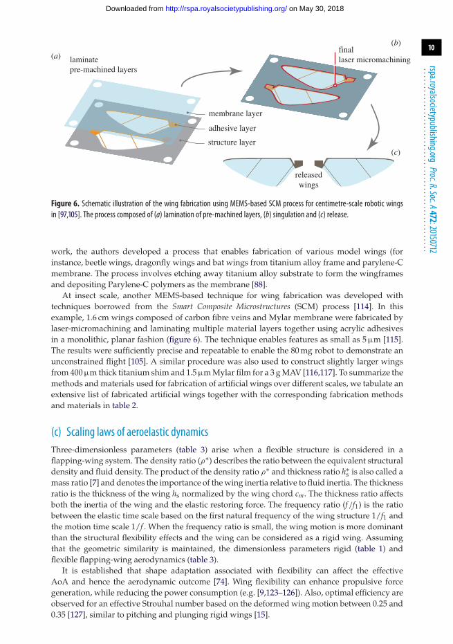
Figure 6. Schematic illustration of the wing fabrication using MEMS-based SCM process for centimetre-scale robotic wingsin [97,105]. The process composed of (a) lamination of pre-machined layers, (b) singulation and (c) release.
work, the authors developed a process that enables fabrication of various model wings (forinstance, beetle wings, dragonfly wings and bat wings from titanium alloy frame and parylene-Cmembrane. The process involves etching away titanium alloy substrate to form the wingframesand depositing Parylene-C polymers as the membrane [88].
At insect scale, another MEMS-based technique for wing fabrication was developed withtechniques borrowed from the Smart Composite Microstructures (SCM) process [114]. In thisexample, 1.6 cm wings composed of carbon fibre veins and Mylar membrane were fabricated bylaser-micromachining and laminating multiple material layers together using acrylic adhesivesin a monolithic, planar fashion (figure 6). The technique enables features as small as 5 µm [115].The results were sufficiently precise and repeatable to enable the 80 mg robot to demonstrate anunconstrained flight [105]. A similar procedure was also used to construct slightly larger wingsfrom 400 µm thick titanium shim and 1.5 µm Mylar film for a 3 g MAV [116,117]. To summarize themethods and materials used for fabrication of artificial wings over different scales, we tabulate anextensive list of fabricated artificial wings together with the corresponding fabrication methodsand materials in table 2.
(c) Scaling laws of aeroelastic dynamicsThree-dimensionless parameters (table 3) arise when a flexible structure is considered in aflapping-wing system. The density ratio (ρ∗) describes the ratio between the equivalent structuraldensity and fluid density. The product of the density ratio ρ∗ and thickness ratio h∗
s is also called amass ratio [7] and denotes the importance of the wing inertia relative to fluid inertia. The thicknessratio is the thickness of the wing hs normalized by the wing chord cm. The thickness ratio affectsboth the inertia of the wing and the elastic restoring force. The frequency ratio (f/f1) is the ratiobetween the elastic time scale based on the first natural frequency of the wing structure 1/f1 andthe motion time scale 1/f . When the frequency ratio is small, the wing motion is more dominantthan the structural flexibility effects and the wing can be considered as a rigid wing. Assumingthat the geometric similarity is maintained, the dimensionless parameters rigid (table 1) andflexible flapping-wing aerodynamics (table 3).
It is established that shape adaptation associated with flexibility can affect the effectiveAoA and hence the aerodynamic outcome [74]. Wing flexibility can enhance propulsive forcegeneration, while reducing the power consumption (e.g. [9,123–126]). Also, optimal efficiency areobserved for an effective Strouhal number based on the deformed wing motion between 0.25 and0.35 [127], similar to pitching and plunging rigid wings [15].
on May 30, 2018http://rspa.royalsocietypublishing.org/Downloaded from
11
rspa.royalsocietypublishing.orgProc.R.Soc.A472:20150712
...................................................
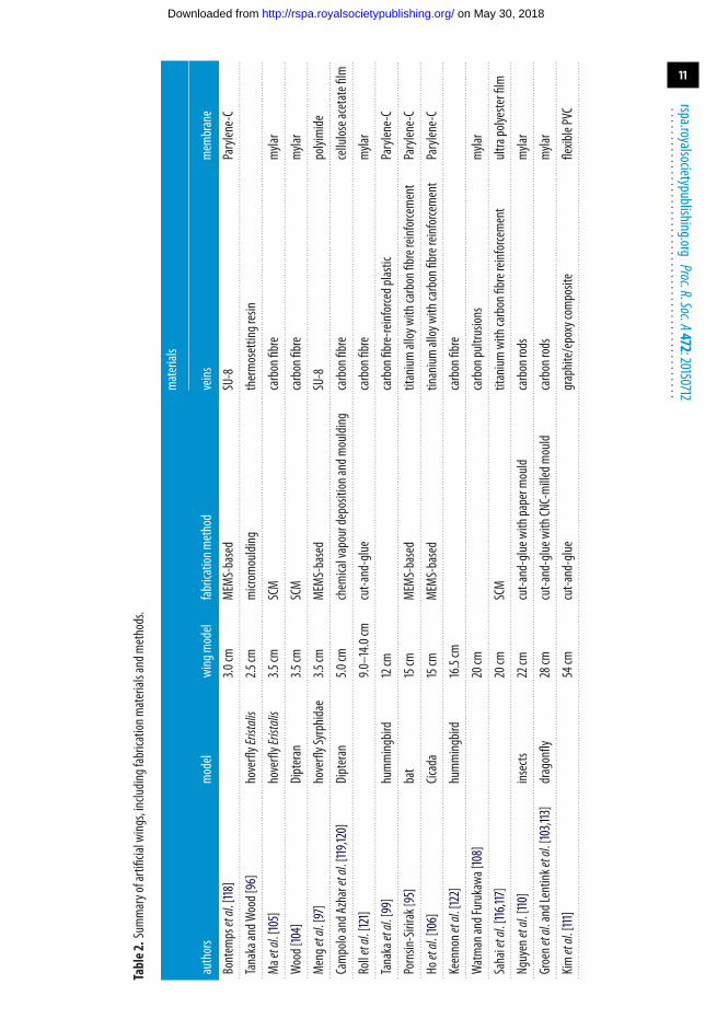
Table2.Sum
maryofartificialwings,including
fabrication
materialsandmethods.
materials
authors
model
wingmodel
fabrication
method
veins
membrane
Bontempsetal.[118]
3.0cm
MEMS-based
SU-8
Parylene-C
.............................................................................................................................................................................................................................................................................................................................................
TanakaandW
ood[96]
hoverflyEristalis
2.5cm
microm
oulding
thermosettingresin
.............................................................................................................................................................................................................................................................................................................................................
Maetal.[105]
hoverflyEristalis
3.5cm
SCM
carbonfibre
mylar
.............................................................................................................................................................................................................................................................................................................................................
Wood[104]
Dipteran
3.5cm
SCM
carbonfibre
mylar
.............................................................................................................................................................................................................................................................................................................................................
Mengetal.[97]
hoverflySyrphidae
3.5cm
MEMS-based
SU-8
polyimide
.............................................................................................................................................................................................................................................................................................................................................
CampoloandA
zharetal.[119,120]
Dipteran
5.0cm
chemicalvapourdepositionandm
oulding
carbonfibre
celluloseacetatefilm
.............................................................................................................................................................................................................................................................................................................................................
Rolletal.[121]
9.0–14.0
cmcut-and-glue
carbonfibre
mylar
.............................................................................................................................................................................................................................................................................................................................................
Tanakaetal.[99]
hummingbird
12cm
carbonfibre-reinforcedplastic
Parylene-C
.............................................................................................................................................................................................................................................................................................................................................
Pornsin-Sirirak[95]
bat
15cm
MEMS-based
titanium
alloywithcarbonfibrereinforcement
Parylene-C
.............................................................................................................................................................................................................................................................................................................................................
Hoetal.[106]
Cicada
15cm
MEMS-based
tinanium
alloywithcarbonfibrereinforcement
Parylene-C
.............................................................................................................................................................................................................................................................................................................................................
Keennonetal.[122]
hummingbird
16.5cm
carbonfibre
.............................................................................................................................................................................................................................................................................................................................................
WatmanandFurukawa[108]
20cm
carbonpultrusions
mylar
.............................................................................................................................................................................................................................................................................................................................................
Sahaietal.[116,117]
20cm
SCM
titanium
withcarbonfibrereinforcement
ultrapolyesterfilm
.............................................................................................................................................................................................................................................................................................................................................
Nguyenetal.[110]
insects
22cm
cut-and-glue
withpaperm
ould
carbonrods
mylar
.............................................................................................................................................................................................................................................................................................................................................
Groenetal.andLentink
etal.[103,113]
dragonfly
28cm
cut-and-glue
withCNC-milledm
ould
carbonrods
mylar
.............................................................................................................................................................................................................................................................................................................................................
Kimetal.[111]
54cm
cut-and-glue
graphite/epoxycom
posite
flexiblePVC
.............................................................................................................................................................................................................................................................................................................................................
on May 30, 2018http://rspa.royalsocietypublishing.org/Downloaded from
12
rspa.royalsocietypublishing.orgProc.R.Soc.A472:20150712
...................................................
log10 g
–lo
g 10 C
L*
0.34
2.0
g
g
–6 –4 –2 0 2–6
–4
–2
0
2
4
6
moth: s
moth: c
bee: sbee: c
fly: sfly: c
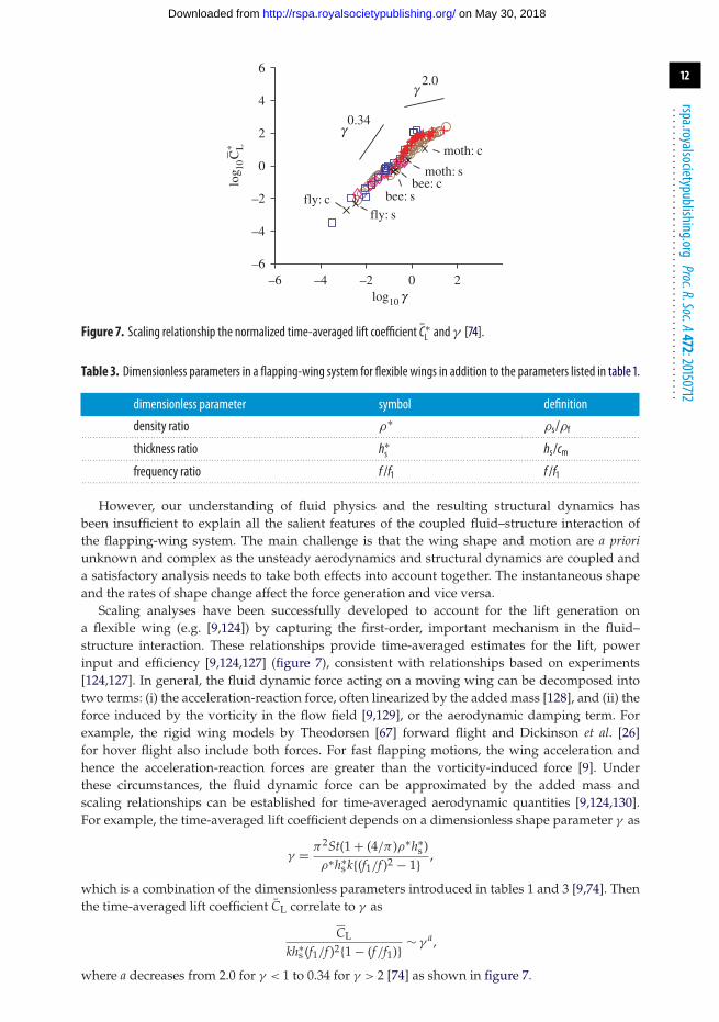
Figure 7. Scaling relationship the normalized time-averaged lift coefficient C∗L and γ [74].
Table 3. Dimensionless parameters in a flapping-wing system for flexible wings in addition to the parameters listed in table 1.
dimensionless parameter symbol definition
density ratio ρ∗ ρs/ρf. . . . . . . . . . . . . . . . . . . . . . . . . . . . . . . . . . . . . . . . . . . . . . . . . . . . . . . . . . . . . . . . . . . . . . . . . . . . . . . . . . . . . . . . . . . . . . . . . . . . . . . . . . . . . . . . . . . . . . . . . . . . . . . . . . . . . . . . . . . . . . . . . . . . . . . . . . . . . . . . . . . . . . . . . . . . . . . . . . . . . . . . . . . . . . . . . . . . . . . . . .
thickness ratio h∗s hs/cm. . . . . . . . . . . . . . . . . . . . . . . . . . . . . . . . . . . . . . . . . . . . . . . . . . . . . . . . . . . . . . . . . . . . . . . . . . . . . . . . . . . . . . . . . . . . . . . . . . . . . . . . . . . . . . . . . . . . . . . . . . . . . . . . . . . . . . . . . . . . . . . . . . . . . . . . . . . . . . . . . . . . . . . . . . . . . . . . . . . . . . . . . . . . . . . . . . . . . . . . . .
frequency ratio f /f1 f /f1. . . . . . . . . . . . . . . . . . . . . . . . . . . . . . . . . . . . . . . . . . . . . . . . . . . . . . . . . . . . . . . . . . . . . . . . . . . . . . . . . . . . . . . . . . . . . . . . . . . . . . . . . . . . . . . . . . . . . . . . . . . . . . . . . . . . . . . . . . . . . . . . . . . . . . . . . . . . . . . . . . . . . . . . . . . . . . . . . . . . . . . . . . . . . . . . . . . . . . . . . .
However, our understanding of fluid physics and the resulting structural dynamics hasbeen insufficient to explain all the salient features of the coupled fluid–structure interaction ofthe flapping-wing system. The main challenge is that the wing shape and motion are a prioriunknown and complex as the unsteady aerodynamics and structural dynamics are coupled anda satisfactory analysis needs to take both effects into account together. The instantaneous shapeand the rates of shape change affect the force generation and vice versa.
Scaling analyses have been successfully developed to account for the lift generation ona flexible wing (e.g. [9,124]) by capturing the first-order, important mechanism in the fluid–structure interaction. These relationships provide time-averaged estimates for the lift, powerinput and efficiency [9,124,127] (figure 7), consistent with relationships based on experiments[124,127]. In general, the fluid dynamic force acting on a moving wing can be decomposed intotwo terms: (i) the acceleration-reaction force, often linearized by the added mass [128], and (ii) theforce induced by the vorticity in the flow field [9,129], or the aerodynamic damping term. Forexample, the rigid wing models by Theodorsen [67] forward flight and Dickinson et al. [26]for hover flight also include both forces. For fast flapping motions, the wing acceleration andhence the acceleration-reaction forces are greater than the vorticity-induced force [9]. Underthese circumstances, the fluid dynamic force can be approximated by the added mass andscaling relationships can be established for time-averaged aerodynamic quantities [9,124,130].For example, the time-averaged lift coefficient depends on a dimensionless shape parameter γ as
γ = π2St(1 + (4/π )ρ∗h∗s )
ρ∗h∗s k{(f1/f )2 − 1} ,
which is a combination of the dimensionless parameters introduced in tables 1 and 3 [9,74]. Thenthe time-averaged lift coefficient CL correlate to γ as
CL
kh∗s (f1/f )2{1 − (f/f1)} ∼ γ a,
where a decreases from 2.0 for γ < 1 to 0.34 for γ > 2 [74] as shown in figure 7.
on May 30, 2018http://rspa.royalsocietypublishing.org/Downloaded from
13
rspa.royalsocietypublishing.orgProc.R.Soc.A472:20150712
...................................................
LEV0LEV1
TEV1
TEV0
fruit fly
LEV1
TEV1
TEV1
LEV1
LEV0
TEV0
LEV0
TEV0
t* = 0.500 0.375 0.250 0.125 0
vorticity
water tunnel
–10 0 10
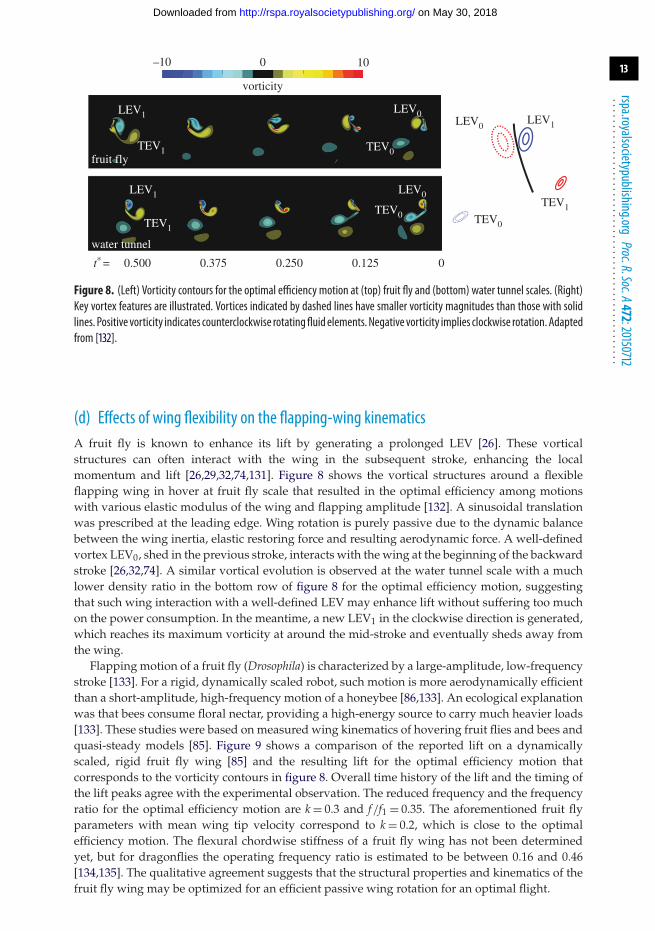
Figure 8. (Left) Vorticity contours for the optimal efficiency motion at (top) fruit fly and (bottom) water tunnel scales. (Right)Key vortex features are illustrated. Vortices indicated by dashed lines have smaller vorticity magnitudes than those with solidlines. Positive vorticity indicates counterclockwise rotatingfluid elements.Negative vorticity implies clockwise rotation. Adaptedfrom [132].
(d) Effects of wing flexibility on the flapping-wing kinematicsA fruit fly is known to enhance its lift by generating a prolonged LEV [26]. These vorticalstructures can often interact with the wing in the subsequent stroke, enhancing the localmomentum and lift [26,29,32,74,131]. Figure 8 shows the vortical structures around a flexibleflapping wing in hover at fruit fly scale that resulted in the optimal efficiency among motionswith various elastic modulus of the wing and flapping amplitude [132]. A sinusoidal translationwas prescribed at the leading edge. Wing rotation is purely passive due to the dynamic balancebetween the wing inertia, elastic restoring force and resulting aerodynamic force. A well-definedvortex LEV0, shed in the previous stroke, interacts with the wing at the beginning of the backwardstroke [26,32,74]. A similar vortical evolution is observed at the water tunnel scale with a muchlower density ratio in the bottom row of figure 8 for the optimal efficiency motion, suggestingthat such wing interaction with a well-defined LEV may enhance lift without suffering too muchon the power consumption. In the meantime, a new LEV1 in the clockwise direction is generated,which reaches its maximum vorticity at around the mid-stroke and eventually sheds away fromthe wing.
Flapping motion of a fruit fly (Drosophila) is characterized by a large-amplitude, low-frequencystroke [133]. For a rigid, dynamically scaled robot, such motion is more aerodynamically efficientthan a short-amplitude, high-frequency motion of a honeybee [86,133]. An ecological explanationwas that bees consume floral nectar, providing a high-energy source to carry much heavier loads[133]. These studies were based on measured wing kinematics of hovering fruit flies and bees andquasi-steady models [85]. Figure 9 shows a comparison of the reported lift on a dynamicallyscaled, rigid fruit fly wing [85] and the resulting lift for the optimal efficiency motion thatcorresponds to the vorticity contours in figure 8. Overall time history of the lift and the timing ofthe lift peaks agree with the experimental observation. The reduced frequency and the frequencyratio for the optimal efficiency motion are k = 0.3 and f/f1 = 0.35. The aforementioned fruit flyparameters with mean wing tip velocity correspond to k = 0.2, which is close to the optimalefficiency motion. The flexural chordwise stiffness of a fruit fly wing has not been determinedyet, but for dragonflies the operating frequency ratio is estimated to be between 0.16 and 0.46[134,135]. The qualitative agreement suggests that the structural properties and kinematics of thefruit fly wing may be optimized for an efficient passive wing rotation for an optimal flight.
on May 30, 2018http://rspa.royalsocietypublishing.org/Downloaded from
14
rspa.royalsocietypublishing.orgProc.R.Soc.A472:20150712
...................................................
0 0.25 0.50 0.75 1.00–1
0
1
2
3
4
5
lift c
oeff
icie
nt
non-dimensional time
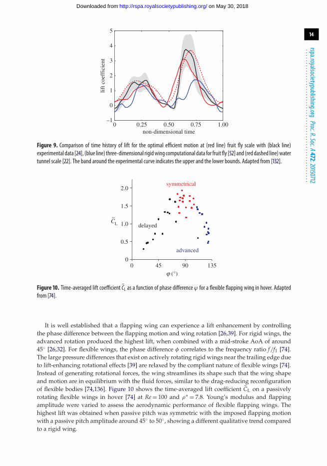
Figure 9. Comparison of time history of lift for the optimal efficient motion at (red line) fruit fly scale with (black line)experimental data [24], (blue line) three-dimensional rigidwing computational data for fruit fly [52] and (red dashed line)watertunnel scale [22]. The band around the experimental curve indicates the upper and the lower bounds. Adapted from [132].
symmetrical
delayed
advanced
j (°)
–CL
00
45 90 135
0.5
1.0
1.5
2.0
Figure 10. Time-averaged lift coefficient CL as a function of phase difference ϕ for a flexible flapping wing in hover. Adaptedfrom [74].
It is well established that a flapping wing can experience a lift enhancement by controllingthe phase difference between the flapping motion and wing rotation [26,39]. For rigid wings, theadvanced rotation produced the highest lift, when combined with a mid-stroke AoA of around45◦ [26,32]. For flexible wings, the phase difference φ correlates to the frequency ratio f/f1 [74].The large pressure differences that exist on actively rotating rigid wings near the trailing edge dueto lift-enhancing rotational effects [39] are relaxed by the compliant nature of flexible wings [74].Instead of generating rotational forces, the wing streamlines its shape such that the wing shapeand motion are in equilibrium with the fluid forces, similar to the drag-reducing reconfigurationof flexible bodies [74,136]. Figure 10 shows the time-averaged lift coefficient CL on a passivelyrotating flexible wings in hover [74] at Re = 100 and ρ∗ = 7.8. Young’s modulus and flappingamplitude were varied to assess the aerodynamic performance of flexible flapping wings. Thehighest lift was obtained when passive pitch was symmetric with the imposed flapping motionwith a passive pitch amplitude around 45◦ to 50◦, showing a different qualitative trend comparedto a rigid wing.
on May 30, 2018http://rspa.royalsocietypublishing.org/Downloaded from
15
rspa.royalsocietypublishing.orgProc.R.Soc.A472:20150712
...................................................
a [º
]C
L
30
45
60
75
90
105
120
0 0.25t/T
0.50–2
0
2
4
6
0 0.25 0.50 0 0.25 0.50t/T t/T
high-fidelityanalytic
(a) (b) (c)
(d) (e) ( f )
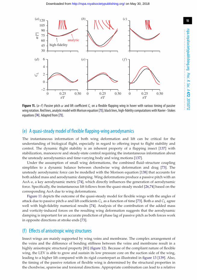
Figure 11. (a–f ) Passive pitch α and lift coefficient CL on a flexible flapping wing in hover with various timing of passivewing rotation. Red lines, analyticmodel withMorison equation [73]; black lines, high-fidelity computationswith Navier–Stokesequations [74]. Adapted from [73].
(e) A quasi-steady model of flexible flapping-wing aerodynamicsThe instantaneous information of both wing deformation and lift can be critical for theunderstanding of biological flight, especially in regard to offering input to flight stability andcontrol. The dynamic flight stability is an inherent property of a flapping insect [137] withstabilization, manoeuvre and steady-state control requiring the instantaneous information aboutthe unsteady aerodynamics and time-varying body and wing motions [137].
Under the assumption of small wing deformations, the combined fluid–structure couplingsimplifies to a dynamic balance between chordwise wing deformation and drag [73]. Theunsteady aerodynamic force can be modelled with the Morison equation [138] that accounts forboth added mass and aerodynamic damping. Wing deformations produce a passive pitch with anAoA α, a key aerodynamic metric [74], which directly influences the generation of aerodynamicforce. Specifically, the instantaneous lift follows from the quasi-steady model [26,74] based on thecorresponding AoA due to wing deformations.
Figure 11 depicts the outcome of the quasi-steady model for flexible wings with the angles ofattack due to passive pitch α and lift coefficients CL as a function of time [73]. Both α and CL agreewell with high-fidelity numerical results [74]. Analysis of the contribution of the added massand vorticity-induced forces on the resulting wing deformation suggests that the aerodynamicdamping is important for an accurate prediction of phase lag of passive pitch as both forces workin opposite directions at stroke ends [73].
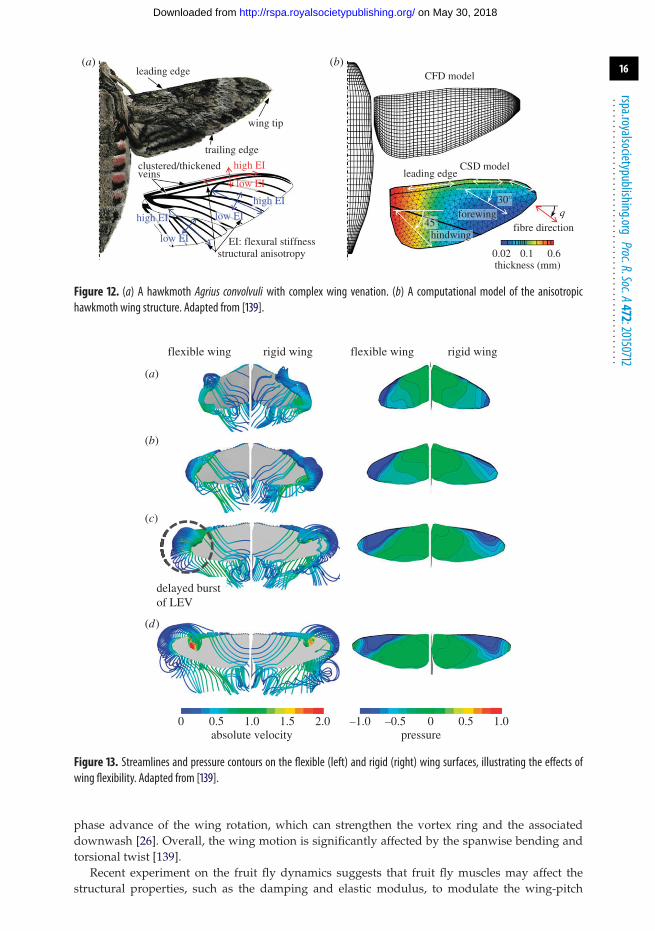
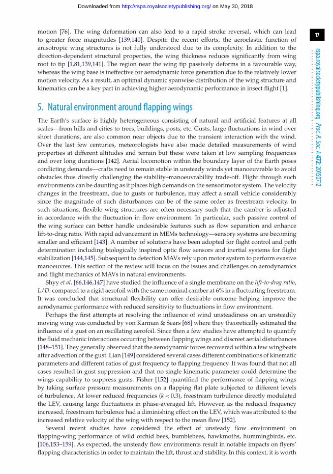
(f) Effects of anisotropic wing structuresInsect wings are mainly supported by wing veins and membrane. The complex arrangement ofthe veins and the difference of bending stiffness between the veins and membrane result in ahighly anisotropic structural property [81] (figure 12). Because of the compliant nature of flexiblewing, the LEV is able to grow and sustain its low pressure core on the suction side of the wing,leading to a higher lift compared with its rigid counterpart as illustrated in figure 13 [139]. Also,the timing of the passive rotation of flexible wing is determined by the structural properties inthe chordwise, spanwise and torsional directions. Appropriate combination can lead to a relative
on May 30, 2018http://rspa.royalsocietypublishing.org/Downloaded from
16
rspa.royalsocietypublishing.orgProc.R.Soc.A472:20150712
...................................................
leading edge CFD model
wing tip
trailing edge
clustered/thickened high EI CSD modelveins
low EIleading edge
high EI
low EIhigh EI q
fibre direction45°
30°forewing
low EI hindwing
thickness (mm)0.10.02 0.6structural anisotropy
EI: flexural stiffness
(a) (b)
Figure 12. (a) A hawkmoth Agrius convolvuli with complex wing venation. (b) A computational model of the anisotropichawkmoth wing structure. Adapted from [139].
flexible wing rigid wing
0 0.5 1.0 1.5 2.0 1.0–1.0 –0.5 0 0.5absolute velocity pressure
delayed burstof LEV
flexible wing rigid wing
(a)
(b)
(c)
(d)
Figure 13. Streamlines and pressure contours on the flexible (left) and rigid (right) wing surfaces, illustrating the effects ofwing flexibility. Adapted from [139].
phase advance of the wing rotation, which can strengthen the vortex ring and the associateddownwash [26]. Overall, the wing motion is significantly affected by the spanwise bending andtorsional twist [139].
Recent experiment on the fruit fly dynamics suggests that fruit fly muscles may affect thestructural properties, such as the damping and elastic modulus, to modulate the wing-pitch
on May 30, 2018http://rspa.royalsocietypublishing.org/Downloaded from
17
rspa.royalsocietypublishing.orgProc.R.Soc.A472:20150712
...................................................
motion [76]. The wing deformation can also lead to a rapid stroke reversal, which can leadto greater force magnitudes [139,140]. Despite the recent efforts, the aeroelastic function ofanisotropic wing structures is not fully understood due to its complexity. In addition to thedirection-dependent structural properties, the wing thickness reduces significantly from wingroot to tip [1,81,139,141]. The region near the wing tip passively deforms in a favourable way,whereas the wing base is ineffective for aerodynamic force generation due to the relatively lowermotion velocity. As a result, an optimal dynamic spanwise distribution of the wing structure andkinematics can be a key part in achieving higher aerodynamic performance in insect flight [1].
5. Natural environment around flapping wingsThe Earth’s surface is highly heterogeneous consisting of natural and artificial features at allscales—from hills and cities to trees, buildings, posts, etc. Gusts, large fluctuations in wind overshort durations, are also common near objects due to the transient interaction with the wind.Over the last few centuries, meteorologists have also made detailed measurements of windproperties at different altitudes and terrain but these were taken at low sampling frequenciesand over long durations [142]. Aerial locomotion within the boundary layer of the Earth posesconflicting demands—crafts need to remain stable in unsteady winds yet manoeuvrable to avoidobstacles thus directly challenging the stability–manoeuvrability trade-off. Flight through suchenvironments can be daunting as it places high demands on the sensorimotor system. The velocitychanges in the freestream, due to gusts or turbulence, may affect a small vehicle considerablysince the magnitude of such disturbances can be of the same order as freestream velocity. Insuch situations, flexible wing structures are often necessary such that the camber is adjustedin accordance with the fluctuation in flow environment. In particular, such passive control ofthe wing surface can better handle undesirable features such as flow separation and enhancelift-to-drag ratio. With rapid advancement in MEMs technology—sensory systems are becomingsmaller and efficient [143]. A number of solutions have been adopted for flight control and pathdetermination including biologically inspired optic flow sensors and inertial systems for flightstabilization [144,145]. Subsequent to detection MAVs rely upon motor system to perform evasivemanoeuvres. This section of the review will focus on the issues and challenges on aerodynamicsand flight mechanics of MAVs in natural environments.
Shyy et al. [66,146,147] have studied the influence of a single membrane on the lift-to-drag ratio,L/D, compared to a rigid aerofoil with the same nominal camber at 6% in a fluctuating freestream.It was concluded that structural flexibility can offer desirable outcome helping improve theaerodynamic performance with reduced sensitivity to fluctuations in flow environment.
Perhaps the first attempts at resolving the influence of wind unsteadiness on an unsteadilymoving wing was conducted by von Karman & Sears [68] where they theoretically estimated theinfluence of a gust on an oscillating aerofoil. Since then a few studies have attempted to quantifythe fluid mechanic interactions occurring between flapping wings and discreet aerial disturbances[148–151]. They generally observed that the aerodynamic forces recovered within a few wingbeatsafter advection of the gust. Lian [149] considered several cases different combinations of kinematicparameters and different ratios of gust frequency to flapping frequency. It was found that not allcases resulted in gust suppression and that no single kinematic parameter could determine thewings capability to suppress gusts. Fisher [152] quantified the performance of flapping wingsby taking surface pressure measurements on a flapping flat plate subjected to different levelsof turbulence. At lower reduced frequencies (k < 0.3), freestream turbulence directly modulatedthe LEV, causing large fluctuations in phase-averaged lift. However, as the reduced frequencyincreased, freestream turbulence had a diminishing effect on the LEV, which was attributed to theincreased relative velocity of the wing with respect to the mean flow [152].
Several recent studies have considered the effect of unsteady flow environment onflapping-wing performance of wild orchid bees, bumblebees, hawkmoths, hummingbirds, etc.[106,153–159]. As expected, the unsteady flow environments result in notable impacts on flyers’flapping characteristics in order to maintain the lift, thrust and stability. In this context, it is worth
on May 30, 2018http://rspa.royalsocietypublishing.org/Downloaded from
18
rspa.royalsocietypublishing.orgProc.R.Soc.A472:20150712
...................................................
noting that, as previously summarized in §1, as a flyer’s size is reduced, its flapping frequencyincreases. For insects, the flapping time scales are substantially shorter than those of the entireflyer. Hence, the flyer adjusts body shape, orientation and inclination over many flapping cycles.In reality, the time scales of, e.g., wind gusts, around a hertz or so, are much slower than flappingwing times. Consequently, the effect of the external flow environment is essentially quasi-steadyfrom the view-point of flapping-wing dynamics, and the vehicle’s stability and responses, whilecomplicated by the flapping patterns, do not have to be treated in a truly unsteady flow context.Variations in winds occurring at time scales many times of the wingbeat rate are likely to havea limited effect on flight control since they may be treated as quasi-steady changes in ambientconditions. For flyers such as bats and birds, the flapping time scale and the body’s time scale arecloser and the impact of the unsteady flow environment needs to be addressed in a continuoustime-dependent framework.
The response to wind-induced disturbances can either be active, passive or a combinationof the two. Active response will include modulation of wing kinematics in response to forcesand torques induced by the wind [153,158,160–162]. Moreover, changing body posture toincrease flight stability has been observed [156]. Other animals such as mosquitoes have devisedpassive strategies to deal with similar conditions. Other mechanisms including flapping countertorque [163,164] and dihedral stability [165] and unconventional mechanisms such as vibrationalstabilization [166] further augment flight stability of flapping wings to aerial disturbance.
Flight in cluttered environment places adds demands on the motor system since it needs tonot only produce the force necessary for weight support but also to perform aerial manoeuvres.To produce additional power flappers can either increase the flapping frequency, amplitudeor feathering angle (or a combination of the three). The control of feathering angle in insectsand in some birds is still relatively unknown with supporting evidence present for both activeand purely passive control. Miniature robotic flapping-winged flyers have generally opted forpassive wing feathering as a means of reducing the control variables without sacrificing onaerodynamic performance [105,167]. Few investigations have also assessed the optimum controlmechanisms for insect-scale flyers [168] and explored design alternatives that adopt a minimalactuation approach [169]. Dimensionally, both amplitude and frequency have similar influenceon force production [170]; however, insects such as honeybees and bumblebees tested usingload-lifting paradigms or in a rarified fluid medium reveal that they generally increase strokeamplitude to increase aerodynamic force [133,160,171]. Other flyers such as hummingbirds canvary flapping frequency [158,172] as well. Increasing amplitude will likely increase the forceproduced at mid-stroke [27], whereas increasing flapping frequency will increase the role ofother phenomena such as wake recapture, rotational lift [26] or passive pitch due to wingflexibility [9,74].
The trade-off between stability and manoeuvrability is considered axiomatic. However,flapping-winged flyers have the potential to maintain both mutually opposing properties.Recent research on the dynamics of fish shows that the production of antagonistic forcesincrease manoeuvrability without sacrificing stability [173]. Similarly, the wing of insectsand birds produce large instantaneous forces while flapping that are not always along thedirection of mean displacement yet they continue to maintain equilibrium since these forcesare cancelled by equal and opposite forces produced by the contralateral wing. Modulation ofthese forces through bilateral asymmetry can produce torques that can be used for performingcorrective manoeuvres in unsteady winds or to take evasive flight when nearing obstacles [165].Additionally, flapping wings have been shown to be more resistant to gusts and freestreamturbulence [149,152].
6. Roles of sensor in flight control and stabilityIn the absence of inherent flight stability as found in flying insects [174,175] or some flapping-wingrobotic systems [105,122], an active control feedback system is essential. Flying insects rely on theprovision of rich sensory feedback across a wide range of modalities. Inputs from across multiple
on May 30, 2018http://rspa.royalsocietypublishing.org/Downloaded from
19
rspa.royalsocietypublishing.orgProc.R.Soc.A472:20150712
...................................................
sensors such as compound eyes, ocelli and antennae are combined and used as feedback to theflight control system at different levels. In artificial flying machines, the equivalent data fusionprocess is also required to amalgamate visual information and data from sensors into functionalforms for state feedback [176,177]. In this section, we explore fundamental characteristics of bothbiological and man-made sensors and their roles in flight stability and control.
(a) Inertial sensorsInertial sensors have become a critical component of MAV flight control system as they providevital information required for attitude stabilization [176,177]. Flying insects equipped with suchsensors are under various forms. Halteres of dipteran flies are best known to function underthe same principle as a vibratory gyroscope. It is believed that antennae of some insects mightplay an analogous role to halteres. While inertial data such as rotational and translational ratecan be deduced from visual information, they often suffer from sensorimotor delay associatedwith phototransduction and motion computation in contrast to minimal latency from theaforementioned mechanosensory organs. Given the swift dynamics of small flying insects, thevisual feedback delay (estimated to be 50–100 ms or 10–20 wing strokes in fruit flies) can lead toinstability as it often exceeds the tolerable latency as predicted by the linear system theories [92].
(i) Halteres
While many flying insects possess two pairs of wings, in houseflies and their relatives the dipteraninsects, their hind pair has been modified into mechanosensory organs known as halteres.These club-shaped structures, oscillating up and down at wingbeat frequency, are believed to besensitive to Coriolis forces during aerial manoeuvres for measurement of body angular velocities[178]. It is thought that the mechasensory reflex from halteres is crucial for attitude stabilizationin dipteran flies [179]. It was reported that removal of halteres radically changes the behaviour ofCalliphora, causing them to crash immediately when thrown into the air [180]. Similarly, Ristrophet al. showed that haltere-disabled fruit flies were unable to maintain stable flight [92].
Based on the dynamics of flies or insect-scale flapping-wing robots, theoretical frameworkssuggest that rotational rate feedback alone is sufficient for attitude stabilization [181,182]. Whilerotational rate feedback may also be obtained from processing visual information, it may not beadequate when the sensorimotor delay of feedback is taken into account. Using linear systemtheories, Ristroph et al. [92] estimated values of tolerable latency or reaction time of the sensory-motor flight control systems of various insects. The theoretical value of tolerable reaction time offruit fly is 13 ms—far below the latency of the visual system (≈50 ms), but notably longer thanthe haltere response found in [183]. The study explains why visual feedback alone is insufficientfor flight stability, whereas the low latency of haltere feedback enables hard-wired equilibriumreflexes for attitude stability in dipteran insects.
The absence of halteres in other flying insects could be partially explained by the presence ofother sensors playing similar roles. For instance, vibrating antennae in hawkmoths was foundto hold a similar role of mediating flight stability during manoeuvres [184,185]. The antennalvibrations are transduced in a frequency range characteristic to the Coriolis input. As a result,removal of the antennal flagellum acutely disrupted flight stability in moths [184]. In addition tohalteres and antenna, it is also known that most flying insects carry simple light sensors knownas ocelli that might allow them to rapidly perform self-righting manoeuvres. However, it is stillunverified how other insects such as honeybees accomplish attitude stabilization [182].
(ii) Ocelli
Adult insects typically possess two compound eyes and three ocelli [186]. These ocelli, orrudimentary defocused light sensors, are situated dorsally to view the entire upper hemisphere.While their precise role in flight stabilization is not completely understood [187], it is believedthat ocelli may function synergistically with the compound eyes to minimize the delay of visual
on May 30, 2018http://rspa.royalsocietypublishing.org/Downloaded from
20
rspa.royalsocietypublishing.orgProc.R.Soc.A472:20150712
...................................................
(a) (b)
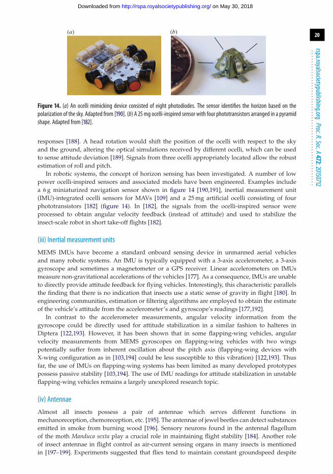
Figure 14. (a) An ocelli mimicking device consisted of eight photodiodes. The sensor identifies the horizon based on thepolarization of the sky. Adapted from [190]. (b) A 25 mg ocelli-inspired sensor with four phototransistors arranged in a pyramidshape. Adapted from [182].
responses [188]. A head rotation would shift the position of the ocelli with respect to the skyand the ground, altering the optical simulations received by different ocelli, which can be usedto sense attitude deviation [189]. Signals from three ocelli appropriately located allow the robustestimation of roll and pitch.
In robotic systems, the concept of horizon sensing has been investigated. A number of lowpower ocelli-inspired sensors and associated models have been engineered. Examples includea 6 g miniaturized navigation sensor shown in figure 14 [190,191], inertial measurement unit(IMU)-integrated ocelli sensors for MAVs [109] and a 25 mg artificial ocelli consisting of fourphototransistors [182] (figure 14). In [182], the signals from the ocelli-inspired sensor wereprocessed to obtain angular velocity feedback (instead of attitude) and used to stabilize theinsect-scale robot in short take-off flights [182].
(iii) Inertial measurement units
MEMS IMUs have become a standard onboard sensing device in unmanned aerial vehiclesand many robotic systems. An IMU is typically equipped with a 3-axis accelerometer, a 3-axisgyroscope and sometimes a magnetometer or a GPS receiver. Linear accelerometers on IMUsmeasure non-gravitational accelerations of the vehicles [177]. As a consequence, IMUs are unableto directly provide attitude feedback for flying vehicles. Interestingly, this characteristic parallelsthe finding that there is no indication that insects use a static sense of gravity in flight [180]. Inengineering communities, estimation or filtering algorithms are employed to obtain the estimateof the vehicle’s attitude from the accelerometer’s and gyroscope’s readings [177,192].
In contrast to the accelerometer measurements, angular velocity information from thegyroscope could be directly used for attitude stabilization in a similar fashion to halteres inDiptera [122,193]. However, it has been shown that in some flapping-wing vehicles, angularvelocity measurements from MEMS gyroscopes on flapping-wing vehicles with two wingspotentially suffer from inherent oscillation about the pitch axis (flapping-wing devices withX-wing configuration as in [103,194] could be less susceptible to this vibration) [122,193]. Thusfar, the use of IMUs on flapping-wing systems has been limited as many developed prototypespossess passive stability [103,194]. The use of IMU readings for attitude stabilization in unstableflapping-wing vehicles remains a largely unexplored research topic.
(iv) Antennae
Almost all insects possess a pair of antennae which serves different functions inmechanoreception, chemoreception, etc. [195]. The antennae of jewel beetles can detect substancesemitted in smoke from burning wood [196]. Sensory neurons found in the antennal flagellumof the moth Manduca sexta play a crucial role in maintaining flight stability [184]. Another roleof insect antennae in flight control as air-current sensing organs in many insects is mentionedin [197–199]. Experiments suggested that flies tend to maintain constant groundspeed despite
on May 30, 2018http://rspa.royalsocietypublishing.org/Downloaded from
21
rspa.royalsocietypublishing.orgProc.R.Soc.A472:20150712
...................................................
changes in wind speed, implicating the presence of an active feedback regulator [200]. It isspeculated that incident wind causes the deflection of arista. The deflection, which superimposesupon the small antennal oscillations at wingbeat frequency, is then detected by the stretch-sensitive scolopalial receptor called the Johnston Organ on the flagellum [188]. While visioncan also provide flight speed feedback, its long latency may have adverse effects. Fuller et al.[201] demonstrated that Drosophila rely on short delay response (approx. 20 ms) from antennaeto augment the visual response that has the sensorimotor delay of 50–100 ms to actively regulateflight speed, resulting in a multi-model sensory feedback architecture. Without fast feedback fromthe antennae, the feedback loop with high gain is susceptible to instability.
Small flapping-wing robots operating in outdoor environments are susceptible to winddisturbances [160]. The effects from damping force and torque are amplified by the flappingmotion of the wings [92,201]. Combined with inherent instability, fast corrective feedback is likelyto be crucial to maintain attitude stability. Small MEMS-based air sensors have been proposed[202–204]; nevertheless, they have yet to be implemented and tested on flapping-wing vehicles.
(b) Visual sensingVarious flight behaviours in flapping-wing insects and birds are tightly linked to visual sensing.Vision is critical to navigation [189], landing [205], chasing prey, avoiding obstacles, as well asstabilizing flight [206]. Unlike larger animals that mostly use stereopsis and object recognitionto navigate and estimate distance, tiny insects rely on compound eyes. Consisting of numeroussimple facets, compound eyes are very sensitive to motion [189]. Accordingly, insects rely oncalculations of optic flow, which provide a measure of the ratio of velocity to distance, to processdirectional motion.
(i) Compound eyes
In arthropods, evolution has created a sophisticated imaging system known as compound eyes.A hexagonal eye lattice of the compound eyes consists of hundreds or thousands of individualphotoreceptor units or ommatidia arranged on a convex surface, resulting in an extended visualfield [199,207]. Panoramic vision is a prominent feature of insect visual systems. Visual cues servemultiple purposes in insect flight, for instance, goal-directed behaviour such as visually guidedlanding [208] and evading looming targets [209]. In most circumstances, visual information isoften exploited in the form of optic flow.
(ii) Optic flow
As mentioned, insects rely heavily on vision to perceive their position and velocity relativeto objects around them. While moving through a stationary environment, insects experienceapparent motion of these objects as panoramic retinal image shifts, or optic flow. A formal vectornotion of optic flow was introduced in [210] describing image velocities. The optic flow essentiallymeasures the ratio of movement to the distance of surrounding objects, resulting in nearby objectsappearing to move faster than distant objects. The coupled relationship renders the estimation ofabsolute distance or velocity from optic flow challenging. While local velocity vectors in flowfields of different motions may appear similar, they could be distinct on a global scale. Opticflow fields induced by translation are fundamentally different from those induced by rotation asillustrated in figure 15. Analysing the optic flow field allows the animal to assess its motion anduse this information for control and navigation purposes.
Ample evidence suggests flying insects rely heavily on optic flow. It has been shown thatbees depend on optic flow to avoid obstacles [212,213]. Several studies have confirmed thatmany insects directly control flight speed in the presence of wind disturbance by using opticflow information [201,214,215]. The fact that the magnitude of the optic flow field is inverselyproportional to the distance enables insects to spontaneously modulate the flight speed as afunction of the distance to the ground or corridor in a strategic manner (figure 16). Bees werefound to perform landing manoeuvres by maintaining constant image velocities, allowing the
on May 30, 2018http://rspa.royalsocietypublishing.org/Downloaded from
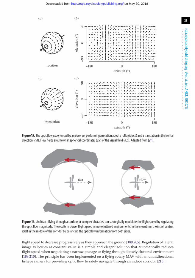
22
rspa.royalsocietypublishing.orgProc.R.Soc.A472:20150712
...................................................
rotation
elev
atio
n (°
)
−180
(a) (b)
(c) (d)−
900
90
elev
atio
n (°
)
−90
090
0 180azimuth (°)
−180 0 180azimuth (°)
translation
Figure 15. The optic flowexperienced by an observer performing a rotation about a roll axis (a,b) and a translation in the frontaldirection (c,d). Flow fields are shown in spherical coordinates (a,c) of the visual field (b,d). Adapted from [211].
fast slow
Figure 16. An insect flying through a corridor or complex obstacles can strategically modulate the flight speed by regulatingthe optic flowmagnitude. The results in slower flight speed inmore cluttered environments. In themeantime, the insect centresitself in the middle of the corridor by balancing the optic flow information from both sides.
flight speed to decrease progressively as they approach the ground [189,205]. Regulation of lateralimage velocities at constant value is a simple and elegant solution that automatically reducesflight speed when negotiating a narrow passage or flying through densely cluttered environment[189,215]. The principle has been implemented on a flying rotary MAV with an omnidirectionalfisheye camera for providing optic flow to safely navigate through an indoor corridor [216].
on May 30, 2018http://rspa.royalsocietypublishing.org/Downloaded from
23
rspa.royalsocietypublishing.orgProc.R.Soc.A472:20150712
...................................................
(iii) Machine vision
Traditional CMOS cameras have been equipped on centimetre-scale flapping-wing robots[122,217]. Similar to insects, vision assists flying robots to autonomously navigate and avoidcollision. Advances in deep learning and object recognition potentially enable vehicles to performvarious tasks such as assisted pollination, reconnaissance, or search and rescue [218].
Vision-based sensors have been successfully incorporated into flying vehicles. Particularlyfor navigation in a GPS-denied environment, a stereo camera and a laser range finder wereequipped onboard for simultaneous localization and mapping algorithms [219,220]. The weightand computation requirements of these sensors render them suitable for large flapping-wingrobots with slower dynamics such as a Robo Raven in [221].
Lightweight flapping-wing vehicles with restricted payload, however, encounter a similarlimitation faced by insects. Processing visual information from traditional cameras iscomputationally and energetically expensive. Several researchers have turned to a biologicallyinspired approach to illustrate the use of low spatial resolution sensors for robot navigationsimilar to the use of optic flow in insects [222–224]. In [223], a 33 mg one-dimensionaloptic-flow-based sensor was mounted on an insect-scale robot to provide altitude feedback ina constrained flight. Curved artificial compound eyes have been developed to produce hightemporal resolution and large field of view images [207,225,226] and deployed for operation offlying robots to provide optic flow cues for guidance [224].
7. Flight dynamics and control in insect flight
(a) Coupled approach and passive versus active stabilizationNatural flyers possess excellent flight control and manoeuvrability while continuously varyingtheir wing kinematics and shapes, as well as body inclination [86,227]. Powered flight in insectsrequires an integrated system consisting of wings to generate aerodynamic force, sensors toassess the flight environment, muscles to move the wings and a control system to modulatepower output from the muscles. Uncovering the novel mechanisms how insects control flightneeds to unpick the dynamic complexity of the sensorimotor neurobiology (motor pattern, centralnervous system and sensory feedback), the musculo-skeletal mechanics (skeletal system, muscleforces, and muscle physiology and anatomy) and the aerodynamics (flexible wing and bodydynamics) [228].
In response to multi-modal sensory input, insects use sensorimotor pathways to modulatepower output from the muscles to the wing. Consequently, a closed-loop system integrating innerworkings of the sensorimotor neurobiology and musculo-skeletal mechanics and an externalmultiple mechanical system is established to handle aerodynamics and structural mechanics offlexible wing and body as well as flight dynamics.
Studies on insect flight stability and manoeuvrability have been conducted mostly based onexperiments in terms of visually mediated response [229–231] and haltere-mediated response[179,232,233]. As discussed, compound eyes, ocelli and halteres of insects play important roles insustaining stability and manoeuvrability. When insects respond to the external environment, thevisual interneuron systems (compound eyes and ocelli) encode optical changes in flow fields suchas slow forward translation, roll or pitch rotation. Motor neurons control neck and wing muscles,which receive the input information from motion-sensitive neurons in the visual system andhalters afferents, and then give corresponding responses to maintain stable flight [234]. Studies onactive control of flying insects indicate that the visual and haltere systems are capable of sensingbody deviation and enable insects to provide compensation reactions in maintaining equilibrium.
In order to understand how the inner control system responds to external perturbations andwhat kind of wing–body kinematics will be employed, the key questions regarding how thewing–body kinematics, the inertial and aerodynamic forces, and the dynamics of body attitudeinteract with each other need to be addressed [175,235]. An integrated multi-mechanical system
on May 30, 2018http://rspa.royalsocietypublishing.org/Downloaded from
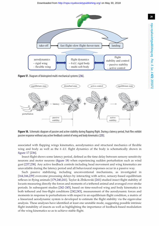
24
rspa.royalsocietypublishing.orgProc.R.Soc.A472:20150712
...................................................
take-off
aerodynamics– rigid wing– flexible wing
– 6 d.f. rigid body– multi-soft body
flight dynamicsflight
stability and control– passive stability– active control
fast flight–slow flight–hover-turn landing
Figure 17. Diagram of bioinspired multi-mechanical systems [236].
equilibrium state disturbed state
latency
perturbation
passivestability
activestability
active control equilibrium state
Figure 18. Schematic diagram of passive and active stability during flapping flight. During a latency period, fruit flies exhibitpassive response without any active feedback control of wing and body kinematics [235].
associated with flapping wings kinematics, aerodynamics and structural mechanics of flexiblewing and body as well as the 6 d.f. flight dynamics of the body is schematically shown infigure 17 [236].
Insect flight shows some latency period, defined as the time delay between sensory sensitivityneurons and motor neurons (figure 18) when experiencing sudden perturbation such as windgust [237,238]. Any active feedback controls including head movement and wing kinematics areunavailable during the latency period and all behavioural responses occur in a passive way.
Such passive stabilizing, including unconventional mechanisms, as investigated in[164,166,239] overcome processing delays by interacting with active, sensory-based equilibriumreflexes in flying animals [179,240,241]. Taylor & Zbikowski [241] studied insect flight stability oflocusts measuring directly the forces and moments of a tethered animal and averaged over strokeperiods. In subsequent studies [242–245], based on time-resolved wing and body kinematics inboth tethered and free-flight conditions [242,243], measurement of the aerodynamic forces andmoments in response to perturbations with respect to an equilibrium flight condition, a matrix ofa linearized aerodynamic system is developed to estimate the flight stability via the eigenvalueanalysis. These analyses have identified at least one unstable mode, suggesting possible intrinsicflight instability of insects as well as highlighting the importance of feedback-based modulationof the wing kinematics so as to achieve stable flight.
on May 30, 2018http://rspa.royalsocietypublishing.org/Downloaded from
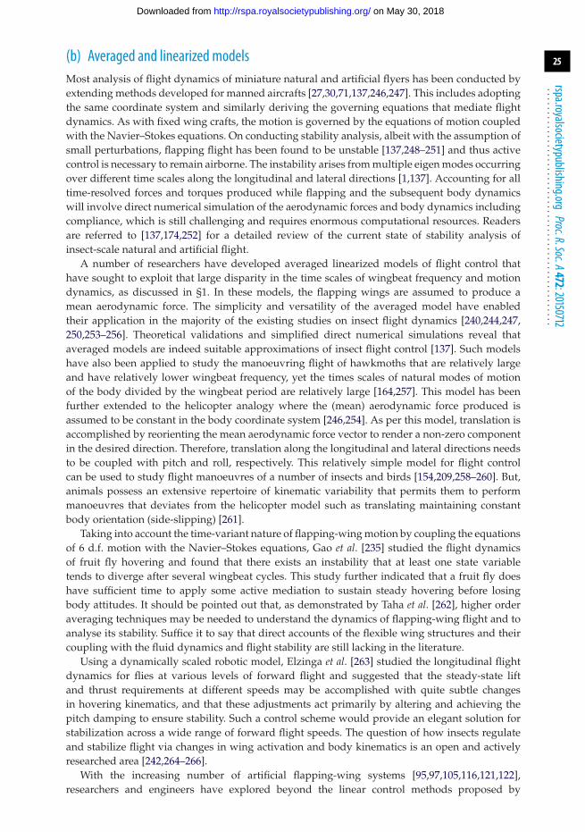
25
rspa.royalsocietypublishing.orgProc.R.Soc.A472:20150712
...................................................
(b) Averaged and linearized modelsMost analysis of flight dynamics of miniature natural and artificial flyers has been conducted byextending methods developed for manned aircrafts [27,30,71,137,246,247]. This includes adoptingthe same coordinate system and similarly deriving the governing equations that mediate flightdynamics. As with fixed wing crafts, the motion is governed by the equations of motion coupledwith the Navier–Stokes equations. On conducting stability analysis, albeit with the assumption ofsmall perturbations, flapping flight has been found to be unstable [137,248–251] and thus activecontrol is necessary to remain airborne. The instability arises from multiple eigen modes occurringover different time scales along the longitudinal and lateral directions [1,137]. Accounting for alltime-resolved forces and torques produced while flapping and the subsequent body dynamicswill involve direct numerical simulation of the aerodynamic forces and body dynamics includingcompliance, which is still challenging and requires enormous computational resources. Readersare referred to [137,174,252] for a detailed review of the current state of stability analysis ofinsect-scale natural and artificial flight.
A number of researchers have developed averaged linearized models of flight control thathave sought to exploit that large disparity in the time scales of wingbeat frequency and motiondynamics, as discussed in §1. In these models, the flapping wings are assumed to produce amean aerodynamic force. The simplicity and versatility of the averaged model have enabledtheir application in the majority of the existing studies on insect flight dynamics [240,244,247,250,253–256]. Theoretical validations and simplified direct numerical simulations reveal thataveraged models are indeed suitable approximations of insect flight control [137]. Such modelshave also been applied to study the manoeuvring flight of hawkmoths that are relatively largeand have relatively lower wingbeat frequency, yet the times scales of natural modes of motionof the body divided by the wingbeat period are relatively large [164,257]. This model has beenfurther extended to the helicopter analogy where the (mean) aerodynamic force produced isassumed to be constant in the body coordinate system [246,254]. As per this model, translation isaccomplished by reorienting the mean aerodynamic force vector to render a non-zero componentin the desired direction. Therefore, translation along the longitudinal and lateral directions needsto be coupled with pitch and roll, respectively. This relatively simple model for flight controlcan be used to study flight manoeuvres of a number of insects and birds [154,209,258–260]. But,animals possess an extensive repertoire of kinematic variability that permits them to performmanoeuvres that deviates from the helicopter model such as translating maintaining constantbody orientation (side-slipping) [261].
Taking into account the time-variant nature of flapping-wing motion by coupling the equationsof 6 d.f. motion with the Navier–Stokes equations, Gao et al. [235] studied the flight dynamicsof fruit fly hovering and found that there exists an instability that at least one state variabletends to diverge after several wingbeat cycles. This study further indicated that a fruit fly doeshave sufficient time to apply some active mediation to sustain steady hovering before losingbody attitudes. It should be pointed out that, as demonstrated by Taha et al. [262], higher orderaveraging techniques may be needed to understand the dynamics of flapping-wing flight and toanalyse its stability. Suffice it to say that direct accounts of the flexible wing structures and theircoupling with the fluid dynamics and flight stability are still lacking in the literature.
Using a dynamically scaled robotic model, Elzinga et al. [263] studied the longitudinal flightdynamics for flies at various levels of forward flight and suggested that the steady-state liftand thrust requirements at different speeds may be accomplished with quite subtle changesin hovering kinematics, and that these adjustments act primarily by altering and achieving thepitch damping to ensure stability. Such a control scheme would provide an elegant solution forstabilization across a wide range of forward flight speeds. The question of how insects regulateand stabilize flight via changes in wing activation and body kinematics is an open and activelyresearched area [242,264–266].
With the increasing number of artificial flapping-wing systems [95,97,105,116,121,122],researchers and engineers have explored beyond the linear control methods proposed by
on May 30, 2018http://rspa.royalsocietypublishing.org/Downloaded from
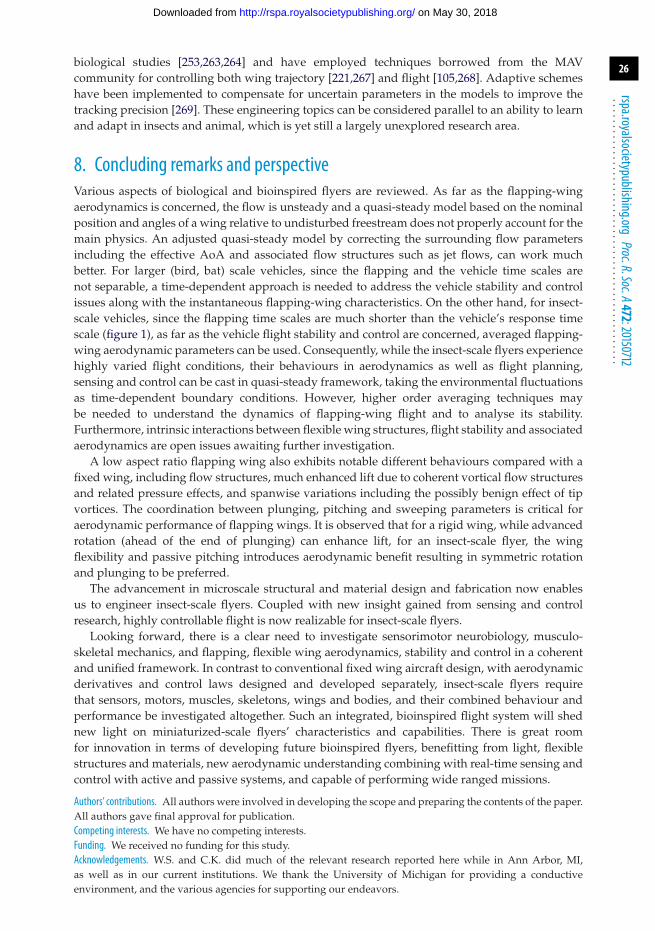
26
rspa.royalsocietypublishing.orgProc.R.Soc.A472:20150712
...................................................
biological studies [253,263,264] and have employed techniques borrowed from the MAVcommunity for controlling both wing trajectory [221,267] and flight [105,268]. Adaptive schemeshave been implemented to compensate for uncertain parameters in the models to improve thetracking precision [269]. These engineering topics can be considered parallel to an ability to learnand adapt in insects and animal, which is yet still a largely unexplored research area.
8. Concluding remarks and perspectiveVarious aspects of biological and bioinspired flyers are reviewed. As far as the flapping-wingaerodynamics is concerned, the flow is unsteady and a quasi-steady model based on the nominalposition and angles of a wing relative to undisturbed freestream does not properly account for themain physics. An adjusted quasi-steady model by correcting the surrounding flow parametersincluding the effective AoA and associated flow structures such as jet flows, can work muchbetter. For larger (bird, bat) scale vehicles, since the flapping and the vehicle time scales arenot separable, a time-dependent approach is needed to address the vehicle stability and controlissues along with the instantaneous flapping-wing characteristics. On the other hand, for insect-scale vehicles, since the flapping time scales are much shorter than the vehicle’s response timescale (figure 1), as far as the vehicle flight stability and control are concerned, averaged flapping-wing aerodynamic parameters can be used. Consequently, while the insect-scale flyers experiencehighly varied flight conditions, their behaviours in aerodynamics as well as flight planning,sensing and control can be cast in quasi-steady framework, taking the environmental fluctuationsas time-dependent boundary conditions. However, higher order averaging techniques maybe needed to understand the dynamics of flapping-wing flight and to analyse its stability.Furthermore, intrinsic interactions between flexible wing structures, flight stability and associatedaerodynamics are open issues awaiting further investigation.
A low aspect ratio flapping wing also exhibits notable different behaviours compared with afixed wing, including flow structures, much enhanced lift due to coherent vortical flow structuresand related pressure effects, and spanwise variations including the possibly benign effect of tipvortices. The coordination between plunging, pitching and sweeping parameters is critical foraerodynamic performance of flapping wings. It is observed that for a rigid wing, while advancedrotation (ahead of the end of plunging) can enhance lift, for an insect-scale flyer, the wingflexibility and passive pitching introduces aerodynamic benefit resulting in symmetric rotationand plunging to be preferred.
The advancement in microscale structural and material design and fabrication now enablesus to engineer insect-scale flyers. Coupled with new insight gained from sensing and controlresearch, highly controllable flight is now realizable for insect-scale flyers.
Looking forward, there is a clear need to investigate sensorimotor neurobiology, musculo-skeletal mechanics, and flapping, flexible wing aerodynamics, stability and control in a coherentand unified framework. In contrast to conventional fixed wing aircraft design, with aerodynamicderivatives and control laws designed and developed separately, insect-scale flyers requirethat sensors, motors, muscles, skeletons, wings and bodies, and their combined behaviour andperformance be investigated altogether. Such an integrated, bioinspired flight system will shednew light on miniaturized-scale flyers’ characteristics and capabilities. There is great roomfor innovation in terms of developing future bioinspired flyers, benefitting from light, flexiblestructures and materials, new aerodynamic understanding combining with real-time sensing andcontrol with active and passive systems, and capable of performing wide ranged missions.
Authors’ contributions. All authors were involved in developing the scope and preparing the contents of the paper.All authors gave final approval for publication.Competing interests. We have no competing interests.Funding. We received no funding for this study.Acknowledgements. W.S. and C.K. did much of the relevant research reported here while in Ann Arbor, MI,as well as in our current institutions. We thank the University of Michigan for providing a conductiveenvironment, and the various agencies for supporting our endeavors.
on May 30, 2018http://rspa.royalsocietypublishing.org/Downloaded from
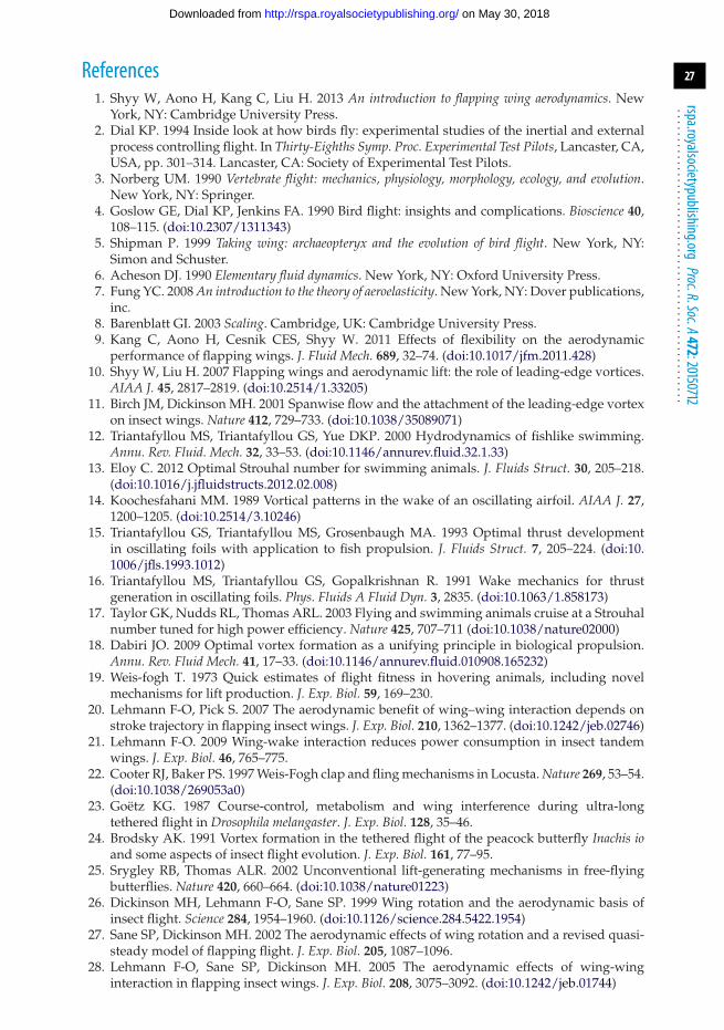
27
rspa.royalsocietypublishing.orgProc.R.Soc.A472:20150712
...................................................
References1. Shyy W, Aono H, Kang C, Liu H. 2013 An introduction to flapping wing aerodynamics. New
York, NY: Cambridge University Press.2. Dial KP. 1994 Inside look at how birds fly: experimental studies of the inertial and external
process controlling flight. In Thirty-Eighths Symp. Proc. Experimental Test Pilots, Lancaster, CA,USA, pp. 301–314. Lancaster, CA: Society of Experimental Test Pilots.
3. Norberg UM. 1990 Vertebrate flight: mechanics, physiology, morphology, ecology, and evolution.New York, NY: Springer.
4. Goslow GE, Dial KP, Jenkins FA. 1990 Bird flight: insights and complications. Bioscience 40,108–115. (doi:10.2307/1311343)
5. Shipman P. 1999 Taking wing: archaeopteryx and the evolution of bird flight. New York, NY:Simon and Schuster.
6. Acheson DJ. 1990 Elementary fluid dynamics. New York, NY: Oxford University Press.7. Fung YC. 2008 An introduction to the theory of aeroelasticity. New York, NY: Dover publications,
inc.8. Barenblatt GI. 2003 Scaling. Cambridge, UK: Cambridge University Press.9. Kang C, Aono H, Cesnik CES, Shyy W. 2011 Effects of flexibility on the aerodynamic
performance of flapping wings. J. Fluid Mech. 689, 32–74. (doi:10.1017/jfm.2011.428)10. Shyy W, Liu H. 2007 Flapping wings and aerodynamic lift: the role of leading-edge vortices.
AIAA J. 45, 2817–2819. (doi:10.2514/1.33205)11. Birch JM, Dickinson MH. 2001 Spanwise flow and the attachment of the leading-edge vortex
on insect wings. Nature 412, 729–733. (doi:10.1038/35089071)12. Triantafyllou MS, Triantafyllou GS, Yue DKP. 2000 Hydrodynamics of fishlike swimming.
Annu. Rev. Fluid. Mech. 32, 33–53. (doi:10.1146/annurev.fluid.32.1.33)13. Eloy C. 2012 Optimal Strouhal number for swimming animals. J. Fluids Struct. 30, 205–218.
(doi:10.1016/j.jfluidstructs.2012.02.008)14. Koochesfahani MM. 1989 Vortical patterns in the wake of an oscillating airfoil. AIAA J. 27,
1200–1205. (doi:10.2514/3.10246)15. Triantafyllou GS, Triantafyllou MS, Grosenbaugh MA. 1993 Optimal thrust development
in oscillating foils with application to fish propulsion. J. Fluids Struct. 7, 205–224. (doi:10.1006/jfls.1993.1012)
16. Triantafyllou MS, Triantafyllou GS, Gopalkrishnan R. 1991 Wake mechanics for thrustgeneration in oscillating foils. Phys. Fluids A Fluid Dyn. 3, 2835. (doi:10.1063/1.858173)
17. Taylor GK, Nudds RL, Thomas ARL. 2003 Flying and swimming animals cruise at a Strouhalnumber tuned for high power efficiency. Nature 425, 707–711 (doi:10.1038/nature02000)
18. Dabiri JO. 2009 Optimal vortex formation as a unifying principle in biological propulsion.Annu. Rev. Fluid Mech. 41, 17–33. (doi:10.1146/annurev.fluid.010908.165232)
19. Weis-fogh T. 1973 Quick estimates of flight fitness in hovering animals, including novelmechanisms for lift production. J. Exp. Biol. 59, 169–230.
20. Lehmann F-O, Pick S. 2007 The aerodynamic benefit of wing–wing interaction depends onstroke trajectory in flapping insect wings. J. Exp. Biol. 210, 1362–1377. (doi:10.1242/jeb.02746)
21. Lehmann F-O. 2009 Wing-wake interaction reduces power consumption in insect tandemwings. J. Exp. Biol. 46, 765–775.
22. Cooter RJ, Baker PS. 1997 Weis-Fogh clap and fling mechanisms in Locusta. Nature 269, 53–54.(doi:10.1038/269053a0)
23. Goëtz KG. 1987 Course-control, metabolism and wing interference during ultra-longtethered flight in Drosophila melangaster. J. Exp. Biol. 128, 35–46.
24. Brodsky AK. 1991 Vortex formation in the tethered flight of the peacock butterfly Inachis ioand some aspects of insect flight evolution. J. Exp. Biol. 161, 77–95.
25. Srygley RB, Thomas ALR. 2002 Unconventional lift-generating mechanisms in free-flyingbutterflies. Nature 420, 660–664. (doi:10.1038/nature01223)
26. Dickinson MH, Lehmann F-O, Sane SP. 1999 Wing rotation and the aerodynamic basis ofinsect flight. Science 284, 1954–1960. (doi:10.1126/science.284.5422.1954)
27. Sane SP, Dickinson MH. 2002 The aerodynamic effects of wing rotation and a revised quasi-steady model of flapping flight. J. Exp. Biol. 205, 1087–1096.
28. Lehmann F-O, Sane SP, Dickinson MH. 2005 The aerodynamic effects of wing-winginteraction in flapping insect wings. J. Exp. Biol. 208, 3075–3092. (doi:10.1242/jeb.01744)
on May 30, 2018http://rspa.royalsocietypublishing.org/Downloaded from
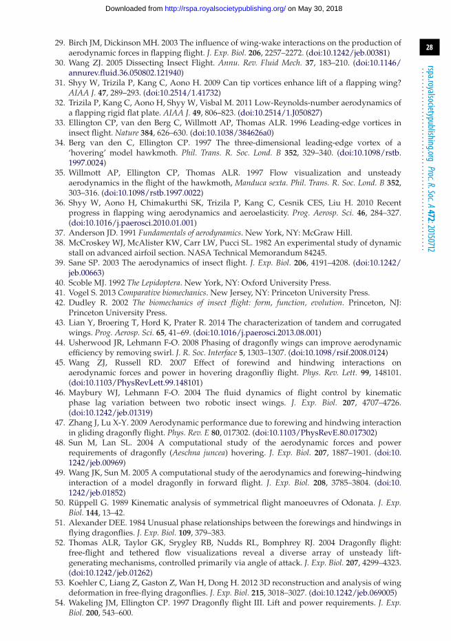
28
rspa.royalsocietypublishing.orgProc.R.Soc.A472:20150712
...................................................
29. Birch JM, Dickinson MH. 2003 The influence of wing-wake interactions on the production ofaerodynamic forces in flapping flight. J. Exp. Biol. 206, 2257–2272. (doi:10.1242/jeb.00381)
30. Wang ZJ. 2005 Dissecting Insect Flight. Annu. Rev. Fluid Mech. 37, 183–210. (doi:10.1146/annurev.fluid.36.050802.121940)
31. Shyy W, Trizila P, Kang C, Aono H. 2009 Can tip vortices enhance lift of a flapping wing?AIAA J. 47, 289–293. (doi:10.2514/1.41732)
32. Trizila P, Kang C, Aono H, Shyy W, Visbal M. 2011 Low-Reynolds-number aerodynamics ofa flapping rigid flat plate. AIAA J. 49, 806–823. (doi:10.2514/1.J050827)
33. Ellington CP, van den Berg C, Willmott AP, Thomas ALR. 1996 Leading-edge vortices ininsect flight. Nature 384, 626–630. (doi:10.1038/384626a0)
34. Berg van den C, Ellington CP. 1997 The three-dimensional leading-edge vortex of a‘hovering’ model hawkmoth. Phil. Trans. R. Soc. Lond. B 352, 329–340. (doi:10.1098/rstb.1997.0024)
35. Willmott AP, Ellington CP, Thomas ALR. 1997 Flow visualization and unsteadyaerodynamics in the flight of the hawkmoth, Manduca sexta. Phil. Trans. R. Soc. Lond. B 352,303–316. (doi:10.1098/rstb.1997.0022)
36. Shyy W, Aono H, Chimakurthi SK, Trizila P, Kang C, Cesnik CES, Liu H. 2010 Recentprogress in flapping wing aerodynamics and aeroelasticity. Prog. Aerosp. Sci. 46, 284–327.(doi:10.1016/j.paerosci.2010.01.001)
37. Anderson JD. 1991 Fundamentals of aerodynamics. New York, NY: McGraw Hill.38. McCroskey WJ, McAlister KW, Carr LW, Pucci SL. 1982 An experimental study of dynamic
stall on advanced airfoil section. NASA Technical Memorandum 84245.39. Sane SP. 2003 The aerodynamics of insect flight. J. Exp. Biol. 206, 4191–4208. (doi:10.1242/
jeb.00663)40. Scoble MJ. 1992 The Lepidoptera. New York, NY: Oxford University Press.41. Vogel S. 2013 Comparative biomechanics. New Jersey, NY: Princeton University Press.42. Dudley R. 2002 The biomechanics of insect flight: form, function, evolution. Princeton, NJ:
Princeton University Press.43. Lian Y, Broering T, Hord K, Prater R. 2014 The characterization of tandem and corrugated
wings. Prog. Aerosp. Sci. 65, 41–69. (doi:10.1016/j.paerosci.2013.08.001)44. Usherwood JR, Lehmann F-O. 2008 Phasing of dragonfly wings can improve aerodynamic
efficiency by removing swirl. J. R. Soc. Interface 5, 1303–1307. (doi:10.1098/rsif.2008.0124)45. Wang ZJ, Russell RD. 2007 Effect of forewind and hindwing interactions on
aerodynamic forces and power in hovering dragonfliy flight. Phys. Rev. Lett. 99, 148101.(doi:10.1103/PhysRevLett.99.148101)
46. Maybury WJ, Lehmann F-O. 2004 The fluid dynamics of flight control by kinematicphase lag variation between two robotic insect wings. J. Exp. Biol. 207, 4707–4726.(doi:10.1242/jeb.01319)
47. Zhang J, Lu X-Y. 2009 Aerodynamic performance due to forewing and hindwing interactionin gliding dragonfly flight. Phys. Rev. E 80, 017302. (doi:10.1103/PhysRevE.80.017302)
48. Sun M, Lan SL. 2004 A computational study of the aerodynamic forces and powerrequirements of dragonfly (Aeschna juncea) hovering. J. Exp. Biol. 207, 1887–1901. (doi:10.1242/jeb.00969)
49. Wang JK, Sun M. 2005 A computational study of the aerodynamics and forewing–hindwinginteraction of a model dragonfly in forward flight. J. Exp. Biol. 208, 3785–3804. (doi:10.1242/jeb.01852)
50. Rüppell G. 1989 Kinematic analysis of symmetrical flight manoeuvres of Odonata. J. Exp.Biol. 144, 13–42.
51. Alexander DEE. 1984 Unusual phase relationships between the forewings and hindwings inflying dragonflies. J. Exp. Biol. 109, 379–383.
52. Thomas ALR, Taylor GK, Srygley RB, Nudds RL, Bomphrey RJ. 2004 Dragonfly flight:free-flight and tethered flow visualizations reveal a diverse array of unsteady lift-generating mechanisms, controlled primarily via angle of attack. J. Exp. Biol. 207, 4299–4323.(doi:10.1242/jeb.01262)
53. Koehler C, Liang Z, Gaston Z, Wan H, Dong H. 2012 3D reconstruction and analysis of wingdeformation in free-flying dragonflies. J. Exp. Biol. 215, 3018–3027. (doi:10.1242/jeb.069005)
54. Wakeling JM, Ellington CP. 1997 Dragonfly flight III. Lift and power requirements. J. Exp.Biol. 200, 543–600.
on May 30, 2018http://rspa.royalsocietypublishing.org/Downloaded from
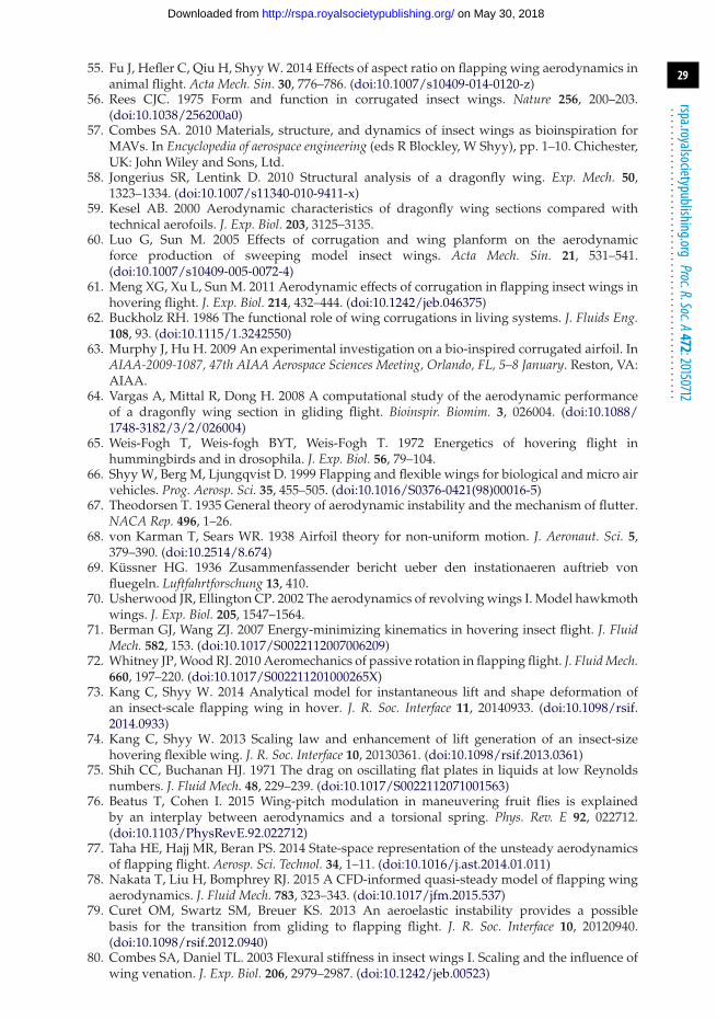
29
rspa.royalsocietypublishing.orgProc.R.Soc.A472:20150712
...................................................
55. Fu J, Hefler C, Qiu H, Shyy W. 2014 Effects of aspect ratio on flapping wing aerodynamics inanimal flight. Acta Mech. Sin. 30, 776–786. (doi:10.1007/s10409-014-0120-z)
56. Rees CJC. 1975 Form and function in corrugated insect wings. Nature 256, 200–203.(doi:10.1038/256200a0)
57. Combes SA. 2010 Materials, structure, and dynamics of insect wings as bioinspiration forMAVs. In Encyclopedia of aerospace engineering (eds R Blockley, W Shyy), pp. 1–10. Chichester,UK: John Wiley and Sons, Ltd.
58. Jongerius SR, Lentink D. 2010 Structural analysis of a dragonfly wing. Exp. Mech. 50,1323–1334. (doi:10.1007/s11340-010-9411-x)
59. Kesel AB. 2000 Aerodynamic characteristics of dragonfly wing sections compared withtechnical aerofoils. J. Exp. Biol. 203, 3125–3135.
60. Luo G, Sun M. 2005 Effects of corrugation and wing planform on the aerodynamicforce production of sweeping model insect wings. Acta Mech. Sin. 21, 531–541.(doi:10.1007/s10409-005-0072-4)
61. Meng XG, Xu L, Sun M. 2011 Aerodynamic effects of corrugation in flapping insect wings inhovering flight. J. Exp. Biol. 214, 432–444. (doi:10.1242/jeb.046375)
62. Buckholz RH. 1986 The functional role of wing corrugations in living systems. J. Fluids Eng.108, 93. (doi:10.1115/1.3242550)
63. Murphy J, Hu H. 2009 An experimental investigation on a bio-inspired corrugated airfoil. InAIAA-2009-1087, 47th AIAA Aerospace Sciences Meeting, Orlando, FL, 5–8 January. Reston, VA:AIAA.
64. Vargas A, Mittal R, Dong H. 2008 A computational study of the aerodynamic performanceof a dragonfly wing section in gliding flight. Bioinspir. Biomim. 3, 026004. (doi:10.1088/1748-3182/3/2/026004)
65. Weis-Fogh T, Weis-fogh BYT, Weis-Fogh T. 1972 Energetics of hovering flight inhummingbirds and in drosophila. J. Exp. Biol. 56, 79–104.
66. Shyy W, Berg M, Ljungqvist D. 1999 Flapping and flexible wings for biological and micro airvehicles. Prog. Aerosp. Sci. 35, 455–505. (doi:10.1016/S0376-0421(98)00016-5)
67. Theodorsen T. 1935 General theory of aerodynamic instability and the mechanism of flutter.NACA Rep. 496, 1–26.
68. von Karman T, Sears WR. 1938 Airfoil theory for non-uniform motion. J. Aeronaut. Sci. 5,379–390. (doi:10.2514/8.674)
69. Küssner HG. 1936 Zusammenfassender bericht ueber den instationaeren auftrieb vonfluegeln. Luftfahrtforschung 13, 410.
70. Usherwood JR, Ellington CP. 2002 The aerodynamics of revolving wings I. Model hawkmothwings. J. Exp. Biol. 205, 1547–1564.
71. Berman GJ, Wang ZJ. 2007 Energy-minimizing kinematics in hovering insect flight. J. FluidMech. 582, 153. (doi:10.1017/S0022112007006209)
72. Whitney JP, Wood RJ. 2010 Aeromechanics of passive rotation in flapping flight. J. Fluid Mech.660, 197–220. (doi:10.1017/S002211201000265X)
73. Kang C, Shyy W. 2014 Analytical model for instantaneous lift and shape deformation ofan insect-scale flapping wing in hover. J. R. Soc. Interface 11, 20140933. (doi:10.1098/rsif.2014.0933)
74. Kang C, Shyy W. 2013 Scaling law and enhancement of lift generation of an insect-sizehovering flexible wing. J. R. Soc. Interface 10, 20130361. (doi:10.1098/rsif.2013.0361)
75. Shih CC, Buchanan HJ. 1971 The drag on oscillating flat plates in liquids at low Reynoldsnumbers. J. Fluid Mech. 48, 229–239. (doi:10.1017/S0022112071001563)
76. Beatus T, Cohen I. 2015 Wing-pitch modulation in maneuvering fruit flies is explainedby an interplay between aerodynamics and a torsional spring. Phys. Rev. E 92, 022712.(doi:10.1103/PhysRevE.92.022712)
77. Taha HE, Hajj MR, Beran PS. 2014 State-space representation of the unsteady aerodynamicsof flapping flight. Aerosp. Sci. Technol. 34, 1–11. (doi:10.1016/j.ast.2014.01.011)
78. Nakata T, Liu H, Bomphrey RJ. 2015 A CFD-informed quasi-steady model of flapping wingaerodynamics. J. Fluid Mech. 783, 323–343. (doi:10.1017/jfm.2015.537)
79. Curet OM, Swartz SM, Breuer KS. 2013 An aeroelastic instability provides a possiblebasis for the transition from gliding to flapping flight. J. R. Soc. Interface 10, 20120940.(doi:10.1098/rsif.2012.0940)
80. Combes SA, Daniel TL. 2003 Flexural stiffness in insect wings I. Scaling and the influence ofwing venation. J. Exp. Biol. 206, 2979–2987. (doi:10.1242/jeb.00523)
on May 30, 2018http://rspa.royalsocietypublishing.org/Downloaded from
30
rspa.royalsocietypublishing.orgProc.R.Soc.A472:20150712
...................................................
81. Combes SA, Daniel TL. 2003 Flexural stiffness in insect wings II. Spatial distribution anddynamic wing bending. J. Exp. Biol. 206, 2989–2997. (doi:10.1242/jeb.00524)
82. Azuma A. 2006 The biokinetics of flying and swimming, 2nd edn. Reston, VA: AIAA Inc.83. Tu M, Dickinson M. 1994 Modulation of negative work output from a steering muscle of the
blowfly Calliphora vicina. J. Exp. Biol. 192, 207–224.84. Lehmann FO, Götz KG. 1996 Activation phase ensures kinematic efficacy in flight-steering
muscles of Drosophila melanogaster. J. Comp. Physiol. A 179, 311–322. (doi:10.1007/BF00194985)85. Fry SN, Sayaman R, Dickinson MH. 2005 The aerodynamics of hovering flight in Drosophila.
J. Exp. Biol. 208, 2303–2318. (doi:10.1242/jeb.01612)86. Sane SP, Dickinson MH. 2001 The control of flight force by a flapping wing: lift and drag
production. J. Exp. Biol. 204, 2607–2626.87. Lehmann F-O, Gorb S, Nasir N, Schutzner P, Schützner P. 2011 Elastic deformation and
energy loss of flapping fly wings. J. Exp. Biol. 214, 2949–2961. (doi:10.1242/jeb.045351)88. Pornsin-Sirirak TN, Tai YC, Nassef H, Ho CM. 2001 Titanium-alloy MEMS wing technology
for a micro aerial vehicle application. Sensors Actuators A Phys. 89, 95–103. (doi:10.1016/S0924-4247(00)00527-6)
89. Tennekes H. 2009 The simple science of flight: from insects to jumbo jets. Cambridge, MA: MITPress.
90. Jane FT. 1997 Jane’s all the World’s aircraft. London, UK: Sampson Low, Marston andCompany.
91. Liu T. 2006 Comparative scaling of flapping- and fixed-wing flyers. AIAA J. 44, 24–33.(doi:10.2514/1.4035)
92. Ristroph L, Ristroph G, Morozova S, Bergou AJ, Chang S, Guckenheimer J, Wang ZJ, CohenI. 2013 Active and passive stabilization of body pitch in insect flight. J. R. Soc. Interface 10,20130237. (doi:10.1098/rsif.2013.0237)
93. Pennycuick CJ. 1975 Mechanics of flight. Avian Biol. 5, 1–75. (doi:10.1016/B978-0-12-249405-5.50009-4)
94. Daniel TL, Combes SA. 2002 Flexible wings and fins: bending by inertial or fluid-dynamicforces? Integr. Comp. Biol. 42, 1044–1049. (doi:10.1093/icb/42.5.1044)
95. Pornsin-Sirirak TN, Tai Y-C, Ho C-M, Keennon M. 2001 Microbat: A palm-sized electricallypowered ornithopter. In Proc. of NASA/JPL Workshop on Biomorphic Robotics, Pasadena, CA,14–17 August, pp. 14–17.
96. Tanaka H, Wood RJ. 2010 Fabrication of corrugated artificial insect wings using lasermicromachined molds. J. Micromech. Microeng. 20, 75008. (doi:10.1088/0960-1317/20/7/075008)
97. Meng K et al. 2012 The design and micromachining of an electromagnetic MEMS flapping-wing micro air vehicle. Microsyst. Technol. 18, 127–136. (doi:10.1007/s00542-011-1388-6)
98. Shang JK, Combes SA, Finio BM, Wood RJ. 2009 Artificial insect wings of diversemorphology for flapping-wing micro air vehicles. Bioinspir. Biomim. 4, 36002. (doi:10.1088/1748-3182/4/3/036002)
99. Tanaka H, Okada H, Shimasue Y, Liu H. 2015 Flexible flapping wings with self-organizedmicrowrinkles. Bioinspir. Biomim. 10, 46005. (doi:10.1088/1748-3190/10/4/046005)
100. Tanaka H, Whitney JP, Wood RJ. 2011 Effect of flexural and torsional wing flexibility on liftgeneration in hoverfly flight. Integr. Comp. Biol. 51, 142–150. (doi:10.1093/icb/icr051)
101. Perez-Rosado A, Gehlhar RD, Nolen S, Gupta SK, Bruck HA. 2015 Design, fabrication,and characterization of multifunctional wings to harvest solar energy in flapping wing airvehicles. Smart Mater. Struct. 24, 65042. (doi:10.1088/0964-1726/24/6/065042)
102. Agrawal A, Agrawal SK. 2009 Design of bio-inspired flexible wings for flapping-wingmicro-sized air vehicle applications. Adv. Robot. 23, 979–1002. (doi:10.1163/156855309X443133)
103. Lentink D, Jongerius SR, Bradshaw NL. 2010 The scalable design of flapping micro-airvehicles inspired by insect flight. In Flying insects and robots (eds D Floreano, J-C Zufferey,MV Srinivasan, C Ellington), pp. 185–205. Berlin, Germany: Springer.
104. Wood RJ. 2007 Design, fabrication, and analysis of a 3DOF, 3 cm flapping-wing MAV. InIntelligent Robots and Systems, 2007. IROS 2007. IEEE/RSJ Int. Conf., San Diego, CA, 29 October–2November, pp. 1576–1581. Piscataway, NJ: IEEE.
105. Ma KY, Chirarattananon P, Fuller SB, Wood RJ 2013 Controlled flight of a biologicallyinspired, insect-scale robot. Science 340, 603–607. (doi:10.1126/science.1231806)
on May 30, 2018http://rspa.royalsocietypublishing.org/Downloaded from
31
rspa.royalsocietypublishing.orgProc.R.Soc.A472:20150712
...................................................
106. Ho S, Nassef H, Pornsinsirirak N, Tai Y-C, Ho C-M. 2003 Unsteady aerodynamics andflow control for flapping wing flyers. Prog. Aerosp. Sci. 39, 635–681. (doi:10.1016/j.paerosci.2003.04.001)
107. Sunada S, Yasuda T, Yasuda K, Kawachi K. 2002 Comparison of wing characteristics at anultralow Reynolds number. J. Aircr. 39, 331–338. (doi:10.2514/2.2931)
108. Watman D, Furukawa T. 2009 A parametric study of flapping wing performance using arobotic flapping wing. In Robotics and Automation, 2009. ICRA’09. IEEE Int. Conf., 12–17 May,Kobe, Japan, pp. 3638–3643. Piscataway, NJ: IEEE.
109. Gremillion G, Humbert JS, Krapp HG. 2014 Bio-inspired modeling and implementationof the ocelli visual system of flying insects. Biol. Cybern. 108, 735–746. (doi:10.1007/s00422-014-0610-x)
110. Nguyen Q-V, Chan WL, Debiasi M. 2015 An insect-inspired flapping wing micro air vehiclewith double wing clap-fling effects and capability of sustained hovering. In SPIE SmartStructures and Materials + Nondestructive Evaluation and Health Monitoring, San Diego, CA,8 March, pp. 94290U. Bellingham, WA: SPIE.
111. Kim D-K, Kim H-I, Han J-H, Kwon K-J. 2007 Experimental investigation on the aerodynamiccharacteristics of a bio-mimetic flapping wing with macro-fiber composites. J. Intell. Mater.Syst. Struct. 19, 423–431.(doi:10.1177/1045389X07083618)
112. Hu H, Kumar AG, Abate G, Albertani R. 2009 An experimental study of flexible membranewings in flapping flight. In 47th AIAA Aerospace Sciences Meeting Including the New HorizonsForum and Aerospace Exposition, Orlando, FL, 5–8 January 2009, pp. 2009–2876. Reston, VA:AIAA.
113. Groen M, Bruggeman B, Remes B, Ruijsink R, Van Oudheusden BW, Bijl H. 2010 Improvingflight performance of the flapping wing MAV DelFly II. In Int. Micro Air Vehicle Conf. andCompetition (IMAV 2010), Braunschweig, Germany, 6–9 July.
114. Wood RJ, Avadhanula S, Sahai R, Steltz E, Fearing RS. 2008 Microrobot design using fiberreinforced composites. J. Mech. Des. 130, 52304. (doi:10.1115/1.2885509)
115. Sreetharan PS, Whitney JP, Strauss MD, Wood RJ. 2012 Monolithic fabrication of millimeter-scale machines. J. Micromech. Microeng. 22, 55027. (doi:10.1088/0960-1317/22/5/055027)
116. Sahai R, Galloway KC, Karpelson M, Wood RJ. 2012 A flapping-wing micro air vehicle withinterchangeable parts for system integration studies. In Intelligent Robots and Systems (IROS),2012 IEEE/RSJ Int. Conf. on Vilamoura, Portugal, 7–12 October, pp. 501–506. Piscataway, NJ:IEEE.
117. Sahai R, Galloway KC, Wood RJ. 2013 Elastic element integration for improvedflapping-wing micro air vehicle performance. Robot. IEEE Trans. 29, 32–41. (doi:10.1109/TRO.2012.2218936)
118. Bontemps A, Vanneste T, Paquet JB, Dietsch T, Grondel S, Cattan E. 2013 Designand performance of an insect-inspired nano air vehicle. Smart Mater. Struct. 22, 14008.(doi:10.1088/0964-1726/22/1/014008)
119. Campolo D, Azhar M, Lau G-K, Sitti M. 2014 Can DC motors directly drive flappingwings at high frequency and large wing strokes? Mech. IEEE/ASME Trans. 19, 109–120.(doi:10.1109/TMECH.2012.2222432)
120. Azhar M, Campolo D, Lau G-K, Hines L, Sitti M. 2013 Flapping wings via direct-driving byDC motors. In Robotics and Automation (ICRA), 2013 IEEE Int. Conf. Karlsruhe, Germany, 6–10May, pp. 1397–1402. Piscataway, NJ: IEEE.
121. Roll J, Cheng B, Deng X (eds). 2013 Design, fabrication, and experiments of anelectromagnetic actuator for flapping wing micro air vehicles. In Robotics and Automation(ICRA), 2013 IEEE Int. Conf., Karlsruhe, Germany, 6–10 May, pp. 809–815.
122. Keennon M, Klingebiel K, Won H, Andriukov A. 2012 Development of the nanohummingbird: a tailless flapping wing micro air vehicle. In AIAA-2012-0588, 50th AIAAAerospace Sciences Meeting, Nashville, TN, 9–12 January. Reston, VA: AIAA.
123. Eldredge JD, Pisani D. 2008 Passive locomotion of a simple articulated fish-like system in thewake of an obstacle. J. Fluid Mech. 607, 279–288. (doi:10.1017/S0022112008002218)
124. Ramananarivo S, Godoy-Diana R, Thiria B. 2011 Rather than resonance, flapping wing flyersmay play on aerodynamics to improve performance. Proc. Natl Acad. Sci. USA 108, 5964–5969.(doi:10.1073/pnas.1017910108)
125. Yin B, Luo H. 2010 Effect of wing inertia on hovering performance of flexible flapping wings.Phys. Fluids 22, 111902. (doi:10.1063/1.3499739)
on May 30, 2018http://rspa.royalsocietypublishing.org/Downloaded from
32
rspa.royalsocietypublishing.orgProc.R.Soc.A472:20150712
...................................................
126. Vanella M, Fitzgerald T, Preidikman S, Balaras E, Balachandran B. 2009 Influence offlexibility on the aerodynamic performance of a hovering wing. J. Exp. Biol. 212, 95–105.(doi:10.1242/jeb.016428)
127. Dewey PA, Boschitsch BM, Moored KW, Stone HA, Smits AJ. 2013 Scaling laws for the thrustproduction of flexible pitching panels. J. Fluid Mech. 732, 29–46. (doi:10.1017/jfm.2013.384)
128. Lamb H. 1945 Hydrodynamics, 6th edn. New York, NY: Dover.129. Saffman PG. 1995 Vortex dynamics. New York, NY: Cambridge University Press.130. Thiria B, Godoy-Diana R. 2010 How wing compliance drives the efficiency of self-propelled
flapping flyers. Phys. Rev. E 82, 15303. (doi:10.1103/PhysRevE.82.015303)131. Lua KB, Lim TT, Yeo KS. 2011 Effect of wing–wake interaction on aerodynamic force
generation on a 2D flapping wing. Exp. Fluids 51, 177–195. (doi:10.1007/s00348-010-1032-8)132. Sridhar M, Kang C. 2015 Aerodynamic performance of two-dimensional, chordwise flexible
flapping wings at fruit fly scale in hover flight. Bioinspir. Biomim. 10, 036007. (doi:10.1088/1748-3190/10/3/036007)
133. Altshuler DL, Dickson WB, Vance JT, Roberts SP, Dickinson MH. 2005 Short-amplitudehigh-frequency wing strokes determine the aerodynamics of honeybee flight. Proc. Natl Acad.Sci. USA 102, 18 213–18 218. (doi:10.1073/pnas.0506590102)
134. Chen J-S, Chen J-Y, Chou Y-F. 2008 On the natural frequencies and mode shapes of dragonflywings. J. Sound Vib. 313, 643–654. (doi:10.1016/j.jsv.2007.11.056)
135. Sunada S, Zeng L, Kawachi K. 1998 The relationship between dragonfly wing structure andtorsional deformation. J. Theor. Biol. 193, 39–45. (doi:10.1006/jtbi.1998.0678)
136. Alben S, Shelley M, Zhang J. 2002 Drag reduction through self-similar bending of a flexiblebody. Nature 420, 479–481. (doi:10.1038/nature01232)
137. Sun M. 2014 Insect flight dynamics: stability and control. Rev. Mod. Phys. 86, 615–646.(doi:10.1103/RevModPhys.86.615)
138. Morison JR, O’Brien MP, Johnson JW, Schaaf SA. 1950 The force exerted by surface waves onpiles. Pet. Trans. 189, 149–154.
139. Nakata T, Liu H. 2012 Aerodynamic performance of a hovering hawkmoth with flexiblewings: a computational approach. Proc. R. Soc. B 279, 722–731. (doi:10.1098/rspb.2011.1023)
140. Mountcastle AM, Combes SA. 2013 Wing flexibility enhances load-lifting capacity inbumblebees. Proc. R. Soc. B 280, 20130531. (doi:10.1098/rspb.2013.0531)
141. Wootton RJ. 1993 Leading edge section and asymmetric twisting in the wings of flyingbutterflies. J. Exp. Biol. 180, 105–117.
142. Walshe DEJ. 1972 Wind-excited oscillations of structures. London, UK: Her Majesty’s StationeryOffice.
143. Karpelson M, Wei G-Y, Wood RJ. 2008 A review of actuation and power electronics optionsfor flapping-wing robotic insects. In 2008 IEEE International Conf. on Robotics and Automation,Pasadena, CA, 19–23 May, pp. 779–786. Piscataway, NJ: IEEE.
144. Floreano D, Zufferey J-C, Srinivasan MV, Ellington C. 2009 Flying insects and robots. Berlin,Germany: Springer.
145. Ruffier F, Franceschini N. 2005 Optic flow regulation: the key to aircraft automatic guidance.Robot. Automous Syst. 50, 177–194. (doi:10.1016/j.robot.2004.09.016)
146. Shyy W, Jenkins DA, Smith RW. 1997 Study of adaptive shape airfoils at low Reynoldsnumber in oscillatory flow. AIAA J. 35, 1545–1548. (doi:10.2514/2.7484)
147. Shyy W, Klevebring F, Nilsson M, Sloan J, Carroll B, Fuentes C. 1999 A study of rigid andflexible low Reynolds number airfoils. J. Aircr. 36, 523–529. (doi:10.2514/2.2487)
148. Lian Y, Shyy W. 2007 Aerodynamics of low Reynolds number plunging airfoil under gustyenvironment. In 45th AIAA Aerospace Sciences Meeting and Exhibit, Reno, NV, 8–11 January,AIAA-2007-71. Reston, VA: AIAA.
149. Lian Y. 2009 Numerical study of a flapping airfoil in gusty environments. In 27th AIAA Appl.Aerodyn. Conf., San Antonio, TX, 22–25 June. Reston, VA: AIAA.
150. Jones M, Yamaleev NK. 2012 The effect of a gust on the flapping wing performance. In 50thAIAA Aerospace Sciences Meeting including the New Horizons Forum and Aerospace Exposition,Nashville, TN, 9–12 January. Reston, VA: AIAA.
151. Jones MA. 2013 CFD analysis and design optimization of flapping wing flows. PhD DissertationNorth Carolina A&T State University, Greensboro, NC.
152. Fisher A. 2013 The effect of freestream turbulence on fixed and flapping micro air vehicle wings.PhD Thesis, Aerospace, Mechanical and Manufacturing Engineering, RMIT University,Melbourne, Australia.
on May 30, 2018http://rspa.royalsocietypublishing.org/Downloaded from

33
rspa.royalsocietypublishing.orgProc.R.Soc.A472:20150712
...................................................
153. Ortega-Jimenez VM, Greeter JSM, Mittal R, Hedrick TL. 2013 Hawkmoth flight stability inturbulent vortex streets. J. Exp. Biol. 216, 4567–4579. (doi:10.1242/jeb.089672)
154. Ravi S, Crall JD, Fisher A, Combes SA. 2013 Rolling with the flow: bumblebees flying inunsteady wakes. J. Exp. Biol. 216, 4299–4309. (doi:10.1242/jeb.090845)
155. Ravi S, Crall JD, McNeilly L, Gagliardi SF, Biewener AA, Combes SA. 2015 Hummingbirdflight stability and control in freestream turbulent winds. J. Exp. Biol. 218, 1444–1452.(doi:10.1242/jeb.114553)
156. Combes SA, Dudley R. 2009 Turbulence-driven instabilities limit insect flight performance.Proc. Natl Acad. Sci. USA 106, 9105–9108. (doi:10.1073/pnas.0902186106)
157. Kim EJ, Wolf M, Ortega-Jimenez VM, Cheng SH, Dudley R. 2014 Hovering performanceof Anna’s hummingbirds (Calypte anna) in ground effect. J. R. Soc. Interface 11, 20140505.(doi:10.1098/rsif.2014.0505)
158. Ortega-Jimenez VM, Sapir N, Wolf M, Variano EA, Dudley R. 2014 Into turbulent air: size-dependent effects of von Karman vortex streets on hummingbird flight kinematics andenergetics. Proc. R. Soc. B 281, 20140180. (doi:10.1098/rspb.2014.0180)
159. Watkins S, Ravi S, Loxton B. 2010 The effect of turbulence on the aerodynamics of lowReynolds number wings. Eng. Lett. 18, 279–285.
160. Vance JT, Faruque I, Humbert JS. 2013 Kinematic strategies for mitigating gust perturbationsin insects. Bioinspir. Biomim. 8, 016004. (doi:10.1088/1748-3182/8/1/016004)
161. Ortega-Jimenez VM, Mittal R, Hedrick TL. 2014 Hawkmoth flight performance in tornado-like whirlwind vortices. Bioinspir. Biomim. 9, 025003. (doi:10.1088/1748-3182/9/2/025003)
162. Ravi S, Crall JD, Gagliardi S, McNeilly L, Biewener AA, Combes SA. 2014 Hummingbirdflight stability and control in freestream turbulent winds. J. Exp. Biol. 218, 1444–1452.(doi:10.1242/jeb.114553)
163. Hedrick TL. 2011 Damping in flapping flight and its implications for manoeuvring, scalingand evolution. J. Exp. Biol. 214, 4073–4081. (doi:10.1242/jeb.047001)
164. Hedrick TL, Cheng B, Deng X. 2009 Wingbeat time and the scaling of passive rotationaldamping in flapping flight. Science 324, 252–255. (doi:10.1126/science.1168431)
165. Alexander DE, Vogel S. 2004 Nature’s flyers: birds, insects, and the biomechanics of flight. 1st edn.Baltimore, MD: JHU Press.
166. Taha HE, Nayfeh AH, Hajj MR. 2014 Effect of the aerodynamic-induced parametric excitationon the longitudinal stability of hovering MAVs/insects. Nonlinear Dyn. 78, 2399–2408.(doi:10.1007/s11071-014-1596-6)
167. Cheng B, Fry SN, Huang Q, Dickson WB, Dickinson MH, Deng X. 2009 Turning dynamicsand passive damping in flapping flight. In 2009 IEEE Int. Conf. on Robotics and Automation,Kobe, Japan, 12–17 May, pp. 1889–1896. Piscataway, NJ: IEEE.
168. Humbert JS, Faruque IA. 2011 Analysis of insect-inspired wingstroke kinematicperturbations for longitudinal control. J. Guid. Control. Dyn. 34, 618–623. (doi:10.2514/1.51912)
169. Taha HE, Nayfeh AH, Hajj MR. 2013 Saturation-based actuation for flapping MAVs inhovering and forward flight. Nonlinear Dyn. 73, 1125–1138. (doi:10.1007/s11071-013-0857-0)
170. Ellington CP. 1984 The aerodynamics of hovering insect flight. VI. Lift and powerrequirements. Phil. Trans. R. Soc. Lond. B 305, 145–181. (doi:10.1098/rstb.1984.0054)
171. Dillon ME, Dudley R. 2014 Surpassing Mt. Everest: extreme flight performance of alpinebumble-bees. Biol. Lett. 10, 20130922. (doi:10.1098/rsbl.2013.0922)
172. Altshuler DL, Dudley R. 2003 Kinematics of hovering hummingbird flight along simulatedand natural elevational gradients. J. Exp. Biol. 206, 3139–3147. (doi:10.1242/jeb.00540)
173. Sefati S, Neveln ID, Roth E, Mitchell TRT, Snyder JB, Maciver MA, Fortune ES, CowanNJ. 2013 Mutually opposing forces during locomotion can eliminate the tradeoff betweenmaneuverability and stability. Proc. Natl Acad. Sci. USA 110, 18 798–18 803. (doi:10.1073/pnas.1309300110)
174. Orlowski CT, Girard AR. 2012 Dynamics, stability, and control analyses of flapping wingmicro-air vehicles. Prog. Aerosp. Sci. 51, 18–30. (doi:10.1016/j.paerosci.2012.01.001)
175. Liang B, Sun M. 2013 Nonlinear flight dynamics and stability of hovering model insects. J. R.Soc. Interface 10, 20130269. (doi:10.1098/rsif.2013.0269)
176. Kumar V, Michael N. 2012 Opportunities and challenges with autonomous micro aerialvehicles. Int. J. Rob. Res. 31, 1279–1291. (doi:10.1177/0278364912455954)
on May 30, 2018http://rspa.royalsocietypublishing.org/Downloaded from

34
rspa.royalsocietypublishing.orgProc.R.Soc.A472:20150712
...................................................
177. Martin P, Salaun E. 2010 The true role of accelerometer feedback in quadrotor control. InRobotics and Automation (ICRA), 2010 IEEE Int. Conf., Anchorage, AK, 3–7 May, pp. 1623–1629.Piscataway, NJ: IEEE.
178. Pringle JWS. 1948 The gyroscopic mechanism of the halteres of Diptera. Phil. Trans. R. Soc.Lond. B 233, 347–384. (doi:10.1098/rstb.1948.0007)
179. Dickinson MH. 1999 Haltere–mediated equilibrium reflexes of the fruit fly, Drosophilamelanogaster. Phil. Trans. R. Soc. Lond. B 354, 903–916. (doi:10.1098/rstb.1999.0442)
180. Hengstenberg R. 1988 Mechanosensory control of compensatory head roll during flightin the blowfly Calliphora erythrocephala Meig. J. Comp. Physiol. A 163, 151–165. (doi:10.1007/BF00612425)
181. Dickson WB, Straw AD, Poelma C, Dickinson MH. 2006 An integrative model of insect flightcontrol. In Proc. of the 44th AIAA Aerospace Sciences Meeting and Exhibit, Reno, NV, 9–12 January,pp. 31–38. Reston, VA: AIAA.
182. Fuller SB, Karpelson M, Censi A, Ma KY, Wood RJ. 2014 Controlling free flight of a roboticfly using an onboard vision sensor inspired by insect ocelli. J. R. Soc. Interface 11, 20140281.(doi:10.1098/rsif.2014.0281)
183. Fox JL, Fairhall AL, Daniel TL. 2010 Encoding properties of haltere neurons enable motionfeature detection in a biological gyroscope. Proc. Natl Acad. Sci. USA 107, 3840–3845.(doi:10.1073/pnas.0912548107)
184. Sane SP, Dieudonné A, Willis MA, Daniel TL. 2007 Antennal mechanosensors mediate flightcontrol in moths. Science 315, 863–866. (doi:10.1126/science.1133598)
185. Hinterwirth AJ, Daniel TL. 2010 Antennae in the hawkmoth Manduca sexta (Lepidoptera,Sphingidae) mediate abdominal flexion in response to mechanical stimuli. J. Comp. Physiol.A 196, 947–956. (doi:10.1007/s00359-010-0578-5)
186. Kalmus H. 1945 Correlations between flight and vision, and particularly between wings andocelli, in jksects. Proc. R. Entomol. Soc. A 20, 84–96. (doi:10.1111/j.1365-3032.1945.tb01072.x)
187. Parsons MM, Krapp HG, Laughlin SB. 2010 Sensor fusion in identified visual interneurons.Curr. Biol. 20, 624–628. (doi:10.1016/j.cub.2010.01.064)
188. Taylor CP. 1981 Contribution of compound eyes and ocelli to steering of locusts in flight: I.Behavioural analysis. J. Exp. Biol. 93, 1–18.
189. Srinivasan MV, Moore RJD, Thurrowgood S, Soccol D, Bland D. 2012 From biology toengineering: insect vision and applications to robotics. Vienna, Austria: Springer.
190. Chahl J, Mizutani A. 2012 Biomimetic attitude and orientation sensors. Sensors J. IEEE 12,289–297. (doi:10.1109/JSEN.2010.2078806)
191. Chahl J, Thakoor S, Le Bouffant N, Stange G, Srinivasan MV, Hine B, Zornetzer S. 2003Bioinspired engineering of exploration systems: a horizon sensor/attitude reference systembased on the dragonfly ocelli for mars exploration applications. J. Robot. Syst. 20, 35–42.(doi:10.1002/rob.10068)
192. Wendel J, Meister O, Schlaile C, Trommer GF. 2006 An integrated GPS/MEMS-IMUnavigation system for an autonomous helicopter. Aerosp. Sci. Technol. 10, 527–533. (doi:10.1016/j.ast.2006.04.002)
193. Fuller SB, Helbling EF, Chirarattananon P, Wood RJ. 2014 Using a MEMS gyroscope tostabilize the attitude of a fly-sized hovering robot. In IMAV 2014: Int. Micro Air Vehicle Conf.and Competition 2014, Delft, The Netherlands, 12–15 August. IMAV.
194. Nakata T, Liu H, Tanaka Y, Nishihashi N, Wang X, Sato A. 2011 Aerodynamicsof a bio-inspired flexible flapping-wing micro air vehicle. Bioinspir. Biomim. 6, 45002.(doi:10.1088/1748-3182/6/4/045002)
195. Schneider D. 1964 Insect antennae. Annu. Rev. Entomol. 9, 103–122. (doi:10.1146/annurev.en.09.010164.000535)
196. Schütz S, Weissbecker B, Hummel HE, Apel K-H, Schmitz H, Bleckmann H. 1999 Insectantenna as a smoke detector. Nature 398, 298–299. (doi:10.1038/18585)
197. Gewecke M. 1974 The antennae of insects as air-current sense organs and their relationship tothe control of flight. In Experimental analysis of insect behaviour, pp. 100–113. Berlin, Germany:Springer.
198. Mamiya A, Straw AD, Tómasson E, Dickinson MH. 2011 Active and passive antennalmovements during visually guided steering in flying Drosophila. J. Neurosci. 31, 6900–6914.(doi:10.1523/JNEUROSCI.0498-11.2011)
199. Taylor GK, Krapp HG. 2007 Sensory systems and flight stability: what do insects measureand why? Adv. In Insect Phys. 34, 231–316. (doi:10.1016/S0065-2806(07)34005-8)
on May 30, 2018http://rspa.royalsocietypublishing.org/Downloaded from
35
rspa.royalsocietypublishing.orgProc.R.Soc.A472:20150712
...................................................
200. Rohrseitz N, Fry SN. 2011 Behavioural system identification of visual flight speed control inDrosophila melanogaster. J. R. Soc. Interface 8, 171–185. (doi:10.1098/rsif.2010.0225)
201. Fuller SB, Straw AD, Peek MY, Murray RM, Dickinson MH. 2014 Flying Drosophila stabilizetheir vision-based velocity controller by sensing wind with their antennae. Proc. Natl Acad.Sci. USA 111, E1182–E1191. (doi:10.1073/pnas.1323529111)
202. Najafi K. 2012 Biomimetic hair sensors: utilizing the third dimension. In Sensors, 2012 IEEE,Taipei, Taiwan, 28–31 October, pp. 1–4.
203. Wang Y-H, Lee C-Y, Chiang C-M. 2007 A MEMS-based air flow sensor with a free-standingmicro-cantilever structure. Sensors 7, 2389–2401. (doi:10.3390/s7102389)
204. Fuller SB, Sands A, Haggerty A, Karpelson M, Wood RJ. 2013 Estimating attitude andwind velocity using biomimetic sensors on a microrobotic bee. In Robotics and Automation(ICRA), 2013 IEEE Int. Conf., Karlsruhe, Germany, 6–10 May, pp. 1374–1380. Piscataway, NJ:IEEE.
205. van Breugel F, Morgansen K, Dickinson MH. 2014 Monocular distance estimation fromoptic flow during active landing maneuvers. Bioinspir. Biomim. 9, 25002. (doi:10.1088/1748-3182/9/2/025002)
206. Windsor SP, Bomphrey RJ, Taylor GK. 2014 Vision-based flight control in the hawkmothHyles lineata. J. R. Soc. Interface 11, 20130921. (doi:10.1098/rsif.2013.0921)
207. Song YM et al. 2013 Digital cameras with designs inspired by the arthropod eye. Nature 497,95–99. (doi:10.1038/nature12083)
208. Baird E, Boeddeker N, Ibbotson MR, Srinivasan MV. 2013 A universal strategy for visuallyguided landing. Proc. Natl Acad. Sci. USA 110, 18 686–18 691. (doi:10.1073/pnas.1314311110)
209. Muijres FT, Elzinga MJ, Melis JM, Dickinson MH. 2014 Flies evade looming targetsby executing rapid visually directed banked turns. Science 344, 172–177. (doi:10.1126/science.1248955)
210. Koenderink JJ, van Doorn AJ. 1987 Facts on optic flow. Biol. Cybern. 56, 247–254. (doi:10.1007/BF00365219)
211. Karmeier K, Krapp HG, Egelhaaf M. 2003 Robustness of the tuning of fly visual interneuronsto rotatory optic flow. J. Neurophysiol. 90, 1626–1634. (doi:10.1152/jn.00234.2003)
212. Dyhr JP, Higgins CM. 2010 The spatial frequency tuning of optic-flow-dependent behaviorsin the bumblebee Bombus impatiens. J. Exp. Biol. 213, 1643–1650. (doi:10.1242/jeb.041426)
213. Baird E, Dacke M. 2012 Visual flight control in naturalistic and artificial environments.J. Comp. Physiol. A 198, 869–876. (doi:10.1007/s00359-012-0757-7)
214. Srinivasan MV, Lehrer M, Kirchner WH, Zhang SW. 1991 Range perception throughapparent image speed in freely flying honeybees. Vis. Neurosci. 6, 519–535. (doi:10.1017/S095252380000136X)
215. Fry SN, Rohrseitz N, Straw AD, Dickinson MH. 2009 Visual control of flight speed inDrosophila melanogaster. J. Exp. Biol. 212, 1120–1130. (doi:10.1242/jeb.020768)
216. Zingg S, Scaramuzza D, Weiss S, Siegwart R. 2010 MAV navigation through indoor corridorsusing optical flow. In Robotics and Automation (ICRA), 2010 IEEE Int. Conf., Anchorage, AK, 3–7May, pp. 3361–3368. Piscataway, NJ: IEEE.
217. De Croon G, De Clercq KME, Ruijsink R, Remes B, De Wagter C. 2009 Design,aerodynamics, and vision-based control of the DelFly. Int. J. Micro Air Veh. 1, 71–97. (doi:10.1260/175682909789498288)
218. LeCun Y, Bengio Y, Hinton G. 2015 Deep learning. Nature 521, 436–444. (doi:10.1038/nature14539)
219. Achtelik M, Bachrach A, He R, Prentice S, Roy N. 2009 Stereo vision and laser odometryfor autonomous helicopters in GPS-denied indoor environments. In SPIE Defense, security,and sensing (eds GR Gerhart, DW Gage, CM Shoemaker), pp. 733219. Unmanned SystemsTechnology XI. Orlando, FL, USA: SPIE.
220. Schmid K, Lutz P, Tomic T, Mair E, Hirschmüller H. 2014 Autonomous vision-based microair vehicle for indoor and outdoor navigation. J. F. Robot. 31, 537–570. (doi:10.1002/rob.21506)
221. Gerdes J et al. 2014 Robo Raven: a flapping-wing air vehicle with highly compliant andindependently controlled wings. Soft Robot. 1, 275–288. (doi:10.1089/soro.2014.0019)
222. Beyeler A, Zufferey J-C, Floreano D. 2009 Vision-based control of near-obstacle flight. Auton.Robots 27, 201–219. (doi:10.1007/s10514-009-9139-6)
on May 30, 2018http://rspa.royalsocietypublishing.org/Downloaded from
36
rspa.royalsocietypublishing.orgProc.R.Soc.A472:20150712
...................................................
223. Duhamel P-EJ, Perez-Arancibia NO, Barrows GL, Wood RJ. 2013 Biologically inspiredoptical-flow sensing for altitude control of flapping-wing microrobots. Mech. IEEE/ASMETrans. 18, 556–568. (doi:10.1109/TMECH.2012.2225635)
224. Expert F, Ruffier F. 2015 Flying over uneven moving terrain based on optic-flow cueswithout any need for reference frames or accelerometers. Bioinspir. Biomim. 10, 26003.(doi:10.1088/1748-3182/10/2/026003)
225. Floreano D et al. 2013 Miniature curved artificial compound eyes. Proc. Natl Acad. Sci. USA110, 9267–9272. (doi:10.1073/pnas.1219068110)
226. Pericet-Camara R, Dobrzynski MK, Juston R, Viollet S, Leitel R, Mallot HA, Floreano D. 2015An artificial elementary eye with optic flow detection and compositional properties. J. R. Soc.Interface 12, 20150414. (doi:10.1098/rsif.2015.0414)
227. Ennos AR. 1989 The kinematics and aerodynamics of the free flight of some Ditpera. J. Exp.Biol. 142, 49–85.
228. Sadaf S, Reddy OV, Sane S, Hasan G. 2015 Neural Control Of Wing Coordination In Flies.Curr. Biol. 25, 80–86. (doi:10.1016/j.cub.2014.10.069)
229. Srinivasan MV. 1977 A visually-evoked roll response in the housefly. J. Comp. Physiol. A 119,1–14. (doi:10.1007/BF00655868)
230. Preiss R, Spork P. 1994 Singificance of reafferent information on yaw rotation in thevisual control of translator flight maneuvers in locusts. Naturwissenschaften 81, 38–40.(doi:10.1007/BF01138562)
231. Card G, Dickinson MH. 2008 Visually mediated motor planning in the escape response ofDrosophila. Curr. Biol. 18, 1300–1307. (doi:10.1016/j.cub.2008.07.094)
232. Nalbach G. 1993 The halteres of the blowfly Calliphora I. Kinematics and dynamics. J. Comp.Physiol. A 173, 293–300. (doi:10.1007/BF00212693)
233. Faruque I, Humbert JS. 2010 Dipteran insect flight dynamics. Part 1: longitudinal motionabout hover. J. Theor. Biol. 264, 538–552. (doi:10.1016/j.jtbi.2010.02.018)
234. Strausfeld NJ, Seyan HS. 1985 Convergence of visual, haltere, and prosternal inputs atneck motor neurons of Calliphora erythrocephala. Cell Tissue Res. 240, 601–615. (doi:10.1007/BF00216350)
235. Gao N, Aono H, Liu H. 2011 Perturbation analysis of 6DoF flight dynamics and passivedynamic stability of hovering fruitfly: Drosophila melanogaster. J. Theor. Biol. 270, 98–111.(doi:10.1016/j.jtbi.2010.11.022)
236. Liu H, Nakata T, Gao N, Maeda M, Aono H, Shyy W. 2010 Micro air vehicle-motivatedcomputational biomechanics in bio-flights: aerodynamics, flight dynamics and maneuveringstability. Acta Mech. Sin. 26, 863–879. (doi:10.1007/s10409-010-0389-5)
237. Trimarchi JR, Murphey RK. 1997 The shaking-B2 mutation disrupts electrical synapses in aflight circuit in adult Drosophila. J. Neurosci. 17, 4700–4710.
238. Fox JL, Daniel TL. 2008 A neural basis for gyroscopic force measurement in the halters ofHolorusia. J. Comp. Physiol. A 194, 887–897. (doi:10.1007/s00359-008-0361-z)
239. Hedrick TL, Daniel TL. 2006 Flight control in the hawkmoth Manduca sexta: the inverseproblem of hovering. J. Exp. Biol. 209, 3114–3130. (doi:10.1242/jeb.02363)
240. Taylor GK, Thomas ALR. 2003 Dynamic flight stability in the desert locust Schistocercagregaria. J. Exp. Biol. 206, 2803–2829. (doi:10.1242/jeb.00501)
241. Taylor GK, Zbikowski R. 2005 Nonlinear time-periodic models of the longitudinalflight dynamics of desert locusts Schistocerca gregaria. J. R. Soc. Interface 2, 197–221.(doi:10.1098/rsif.2005.0036)
242. Ristroph L, Bergou AJ, Ristroph G, Coumes K, Berman GJ, Guckenheimer J, Wang ZJ, CohenI. 2010 Discovering the flight autostabilizer of fruit flies by inducing aerial stumbles. Proc.Natl Acad. Sci. USA 107, 4820–4824. (doi:10.1073/pnas.1000615107)
243. Fry SN, Sayaman R, Dickinson MHM. 2003 The aerodynamics of free-flight maneuvers inDrosophila. Science 300, 495–498. (doi:10.1126/science.1081944)
244. Sun M, Xiong Y. 2005 Dynamic flight stability of a hovering bumblebee. J. Exp. Biol. 208,447–459. (doi:10.1242/jeb.01407)
245. Gao N, Liu H. 2010 A numerical analysis of dynamic flight stability of hawkmoth hoveringpassive dynamic stability of a hovering fruitfly: a comparison between linear and nonlinearmethods. J. Biomech. Sci. Eng. 5, 591–602. (doi:10.1299/jbse.5.591)
246. Taylor GK. 2001 Mechanics and aerodynamics of insect flight control. Biol. Rev. Camb. Phil.Soc. 76, 449–471. (doi:10.1017/S1464793101005759)
on May 30, 2018http://rspa.royalsocietypublishing.org/Downloaded from
37
rspa.royalsocietypublishing.orgProc.R.Soc.A472:20150712
...................................................
247. Taylor GK, Thomas ALR. 2002 Animal flight dynamics. II. Longitudinal stability in flappingflight. J. Theor. Biol. 214, 351–370. (doi:10.1006/jtbi.2001.2470)
248. Sun M, Yu X. 2006 Aerodynamic force generation in hovering flight in a tiny insect. AIAA J.44, 1532–1540. (doi:10.2514/1.17356)
249. Aono H, Liu H. 2008 A numerical study of hovering aerodynamics in flapping insect flight.In Bio-mechanisms of swimming and flying (eds N Kato, S Kamimura), pp. 179–191. Tokyo,Japan: Springer.
250. Xiong Y, Sun M. 2008 Dynamic flight stability of a bumblebee in forward flight. Acta Mech.Sin. 24, 25–36. (doi:10.1007/s10409-007-0121-2)
251. Sun M, Wang JK, Xiong Y. 2007 Dynamic flight stability of hovering insects. Acta Mech. Sin.23, 231–246. (doi:10.1007/s10409-007-0068-3)
252. Taha HE, Hajj MR, Nayfeh AH. 2012 Flight dynamics and control of flapping-wing MAVs: areview. Nonlinear Dyn. 70, 907–939. (doi:10.1007/s11071-012-0529-5)
253. Schenato L. 2003 Analysis and control of flapping flight: from biological to robotic insects.PhD Dissertation University of California, Berkeley, CA.
254. Xinyan D, Schenato L, Wei Chung W, Sastry SS, Deng X, Schenato L, Wu WC, Sastry SS. 2006Flapping flight for biomimetic robotic insects: part I-system modeling. IEEE Trans. Robot. 22,776–788. (doi:10.1109/TRO.2006.875480)
255. Zbikowski R, Ansari SA, Knowles K. 2006 On mathematical modelling of insect flightdynamics in the context of micro air vehicles. Bioinspir. Biomim. 1, R26–R37. (doi:10.1088/1748-3182/1/2/R02)
256. Aono H, Liu H. 2013 Flapping wing aerodynamics of a numerical biological flyer model inhovering flight. Comput. Fluids 85, 85–92. (doi:10.1016/j.compfluid.2012.10.019)
257. Cheng B, Deng X, Hedrick TL. 2011 The mechanics and control of pitching manoeuvres in afreely flying hawkmoth (Manduca sexta). J. Exp. Biol. 214, 4092–4106. (doi:10.1242/jeb.062760)
258. Muijres FT, Elzinga MJ, Iwasaki NA, Dickinson MH. 2015 Body saccades of Drosophilaconsist of stereotyped banked turns. J. Exp. Biol. 218, 864–875. (doi:10.1242/jeb.114280)
259. Iams S. 2012 Free flight of the mosquito Aedes aegypti. arXiv:1205.5260.260. Hedrick TL, Usherwood JR, Biewener AA. 2007 Low speed maneuvering flight of the rose-
breasted cockatoo (Eolophus roseicapillus). II. Inertial and aerodynamic reorientation. J. Exp.Biol. 210, 1912–1924. (doi:10.1242/jeb.002063)
261. Ristroph L, Berman GJ, Bergou AJ, Wang ZJ, Cohen I. 2009 Automated hull reconstructionmotion tracking (HRMT) applied to sideways maneuvers of free-flying insects. J. Exp. Biol.212, 1324–1335. (doi:10.1242/jeb.025502)
262. Taha HEHE, Tahmasian S, Woolsey CA, Nayfeh AHAH, Hajj MRMR. 2015 The need forhigher-order averaging in the stability analysis of hovering, flapping-wing flight. Bioinspir.Biomim. 10, 016002. (doi:10.1088/1748-3190/10/1/016002)
263. Elzinga MJ, van Breugel F, Dickinson MH. 2015 Strategies for the stabilization of longitudinalforward flapping flight revealed using a dynamically-scaled robotic fly. Bioinspir. Biomim. 9,025001. (doi:10.1088/1748-3182/9/2/025001)
264. Elzinga MJ, Dickson WB, Dickinson MH. 2012 The influence of sensory delay on the yawdynamics of a flapping insect. J. R. Soc. Interface 9, 1685–1696. (doi:10.1098/rsif.2011.0699)
265. Doman DB, Oppenheimer MW, Sigthorsson DO. 2010 Wingbeat shape modulation forflapping-wing micro-air-vehicle control during hover. J. Guid. Control. Dyn. 33, 724–739.(doi:10.2514/1.47146)
266. Oppenheimer MW, Doman DB, Sigthorsson DO. 2011 Dynamics and control of a biomimeticvehicle using biased wingbeat forcing functions. J. Guid. Control. Dyn. 34, 204–217. (doi:10.2514/1.49735)
267. Zhang J, Cheng B, Yao B, Deng X. 2015 Adaptive robust wing trajectory control and forcegeneration of flapping wing MAV. In Robotics and Automation (ICRA), 2015 IEEE Int. Conf.,Seattle, WA, 26–30 May, pp. 5852–5857. Piscataway, NJ: IEEE.
268. Chirarattananon P, Ma KY, Wood RJ. 2014 Adaptive control of a millimeter-scale flapping-wing robot. Bioinspir. Biomim. 9, 25004. (doi:10.1088/1748-3182/9/2/025004)
269. Chirarattananon P, Ma KY, Wood RJ. 2014 Fly on the wall. In Biomedical Robotics andBiomechatronics (20145th IEEE RAS & EMBS) Int. Conf., Sao Paulo, Brazil, 12–15 August,pp. 1001–1008. Piscataway, NJ: IEEE.
on May 30, 2018http://rspa.royalsocietypublishing.org/Downloaded from
rspa.royalsocietypublishing.org
CorrectionCite this article: Shyy W, Kang C-k,Chirarattananon P, Ravi S Liu H. 2016Correction to ‘Aerodynamics, sensing andcontrol of insect-scale flapping-wing flight’.Proc. R. Soc. A 472: 20160096.http://dx.doi.org/10.1098/rspa.2016.0096
Correction to ‘Aerodynamics,sensing and control ofinsect-scale flapping-wingflight’Wei Shyy, Chang-kwon Kang, Pakpong
Chirarattananon, Sridhar Ravi and Hao Liu
Proc. R. Soc. A 472, 20150712. (Published online3 February 2016) (doi:10.1098/rspa.2015.0712)
The affiliations for Hao Liu were incorrectly published.The affiliations should have appeared as
Hao Liu4,6
4Graduate School of Engineering, Chiba University,Chiba, Japan6Shanghai-Jiao Tong University and Chiba UniversityInternational, Cooperative Research Centre (SJTU-CUICRC), Minhang, Shanghai, China
2016 The Author(s) Published by the Royal Society. All rights reserved.


![Experimental analysis of submerged flapping foils ... · principles of flapping foil wave propulsion [1,2,3,4]. MOST (Autonomous Vessels) Ltd have developed a long range endurance](https://img.pdfslide.us/doc/110x75/5f061c6a7e708231d4165844/experimental-analysis-of-submerged-iapping-foils-principles-of-iapping-foil.jpg)