Embed Size (px)
Citation preview
1/22
Department of Aerospace EngineeringDelft University of Technology
Three-dimensional numerical simulations offlapping wings at low Reynolds numbers
OpenFOAM Workshop, ZagrebFrank Bos, Bas van Oudheusden, Hester Bijl7-9 June 2007
Overview Modelling Fluent OpenFoam 2D OpenFoam 3D OpenFoam FSI Conclusions 2/22
Department of Aerospace Engineering
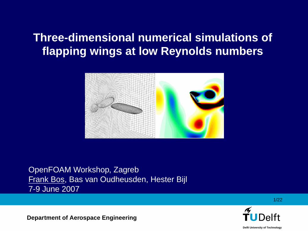
Overview
1. Introduction
2. Background of insect aerodynamics
3. Problem and requirements
4. Equations and Methods
5. Fluent simulations, 2D
6. OpenFOAM simulations
• 2D validation
• 3D flapping wings
• Fluid Structure Interaction
7. Conclusions and (near) future work
Overview Modelling Fluent OpenFoam 2D OpenFoam 3D OpenFoam FSI Conclusions 3/22
Department of Aerospace Engineering
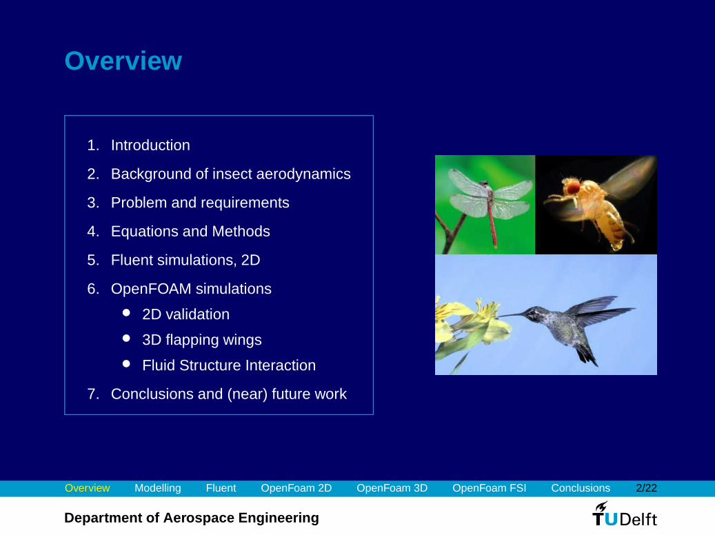
Insect flight for MAV design
Insects are interesting to develop Micro Aerial Vehicles
Examples of application:
1. Intelligence
2. Espionage
3. Investigation of hazardous environments
DelFly (TuDelft):
Possible MAV designs:
Left to right: DelFly (TuDelft), MicroBat (Darpa), MFI (Berkeley)
Overview Modelling Fluent OpenFoam 2D OpenFoam 3D OpenFoam FSI Conclusions 4/22
Department of Aerospace Engineering
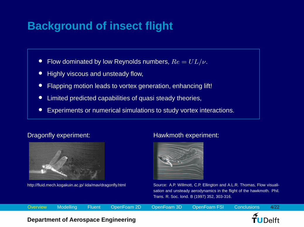
Background of insect flight
• Flow dominated by low Reynolds numbers, Re = UL/ν.
• Highly viscous and unsteady flow,
• Flapping motion leads to vortex generation, enhancing lift!
• Limited predicted capabilities of quasi steady theories,
• Experiments or numerical simulations to study vortex interactions.
Dragonfly experiment:
http://fluid.mech.kogakuin.ac.jp/ iida/mav/dragonfly.html
Hawkmoth experiment:
Source: A.P. Willmott, C.P. Ellington and A.L.R. Thomas, Flow visuali-
sation and unsteady aerodynamics in the flight of the hawkmoth. Phil.Trans. R. Soc. lond. B (1997) 352, 303-316.
Overview Modelling Fluent OpenFoam 2D OpenFoam 3D OpenFoam FSI Conclusions 5/22
Department of Aerospace Engineering
Problem Statement
Problem definition:
• Performance in insect flight is strongly influenced by 3D wing motion,
• For MAV design the forces on flapping wings need to be understood.
CFD model requirements:
• 3D flapping wings (6 DOFs),
• Hovering and forward flight,
• Low Reynolds number, Re=O(100 − 1000),
• (Multiple) wing motion with large amplitudes,
• Fluid Structure Interaction / Body Dynamics coupling.
Overview Modelling Fluent OpenFoam 2D OpenFoam 3D OpenFoam FSI Conclusions 6/22
Department of Aerospace Engineering
Governing equations and flow solvers
Incompressible Navier-Stokes equations:
∂~u∂t
+ (~u · ∇) ~u = −1
ρ∇p + ν∇2~u
Moving mesh using Arbitrary Lagrangrian Eulerian (ALE) formulation:
~u → ~u − ~umesh
Finite volume based general purpose CFD solvers:
• Fluent v6.2 → 2D simulations
• OpenFOAM 1.3/1.4 → 2D/3D simulations and FSI
Overview Modelling Fluent OpenFoam 2D OpenFoam 3D OpenFoam FSI Conclusions 7/22
Department of Aerospace Engineering
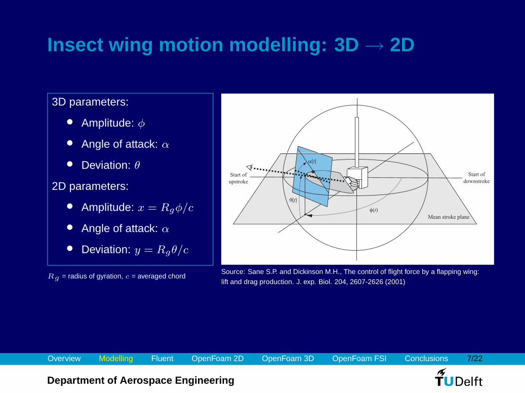
Insect wing motion modelling: 3D → 2D
3D parameters:
• Amplitude: φ
• Angle of attack: α
• Deviation: θ
2D parameters:
• Amplitude: x = Rgφ/c
• Angle of attack: α
• Deviation: y = Rgθ/c
Mean stroke plane
f( )t
Start of
downstroke
Start of
upstroke
a( )t
q( )t
Rg = radius of gyration, c = averaged chordSource: Sane S.P. and Dickinson M.H., The control of flight force by a flapping wing:
lift and drag production. J. exp. Biol. 204, 2607-2626 (2001)
Overview Modelling Fluent OpenFoam 2D OpenFoam 3D OpenFoam FSI Conclusions 8/22
Department of Aerospace Engineering
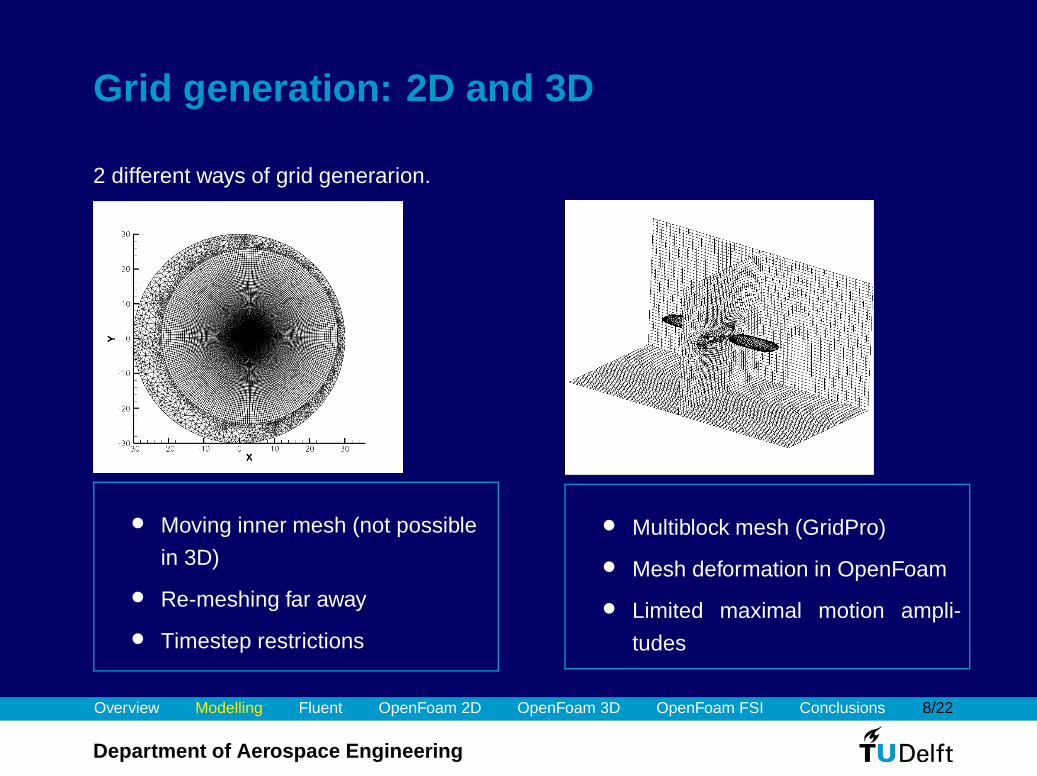
Grid generation: 2D and 3D
2 different ways of grid generarion.
• Moving inner mesh (not possible
in 3D)
• Re-meshing far away
• Timestep restrictions
• Multiblock mesh (GridPro)
• Mesh deformation in OpenFoam
• Limited maximal motion ampli-
tudes
Overview Modelling Fluent OpenFoam 2D OpenFoam 3D OpenFoam FSI Conclusions 9/22
Department of Aerospace Engineering
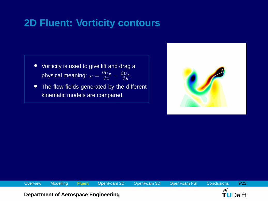
2D Fluent: Vorticity contours
• Vorticity is used to give lift and drag a
physical meaning: ω =∂Uy
∂x−
∂Ux
∂y.
• The flow fields generated by the different
kinematic models are compared.
Overview Modelling Fluent OpenFoam 2D OpenFoam 3D OpenFoam FSI Conclusions 10/22
Department of Aerospace Engineering
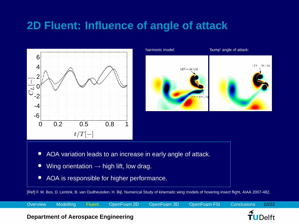
2D Fluent: Influence of angle of attack
t/T [−]
CL[−
]
0 0.2 0.5 0.8 1-6
-4
-2
0
2
4
6harmonic model: ’bump’ angle of attack:
• AOA variation leads to an increase in early angle of attack.
• Wing orientation → high lift, low drag.
• AOA is responsible for higher performance.
[Ref] F. M. Bos, D. Lentink, B. van Oudheusden, H. Bijl, Numerical Study of kinematic wing models of hovering insect flight, AIAA 2007-482.
Overview Modelling Fluent OpenFoam 2D OpenFoam 3D OpenFoam FSI Conclusions 11/22
Department of Aerospace Engineering
Conclusions about 2D simulations
1. Present simulations give good insight in the effect of kinematic motion modelling,
2. Significant performance differences observed for different kinematic models,
3. Simplified kinematics increases drag,
4. Fruit fly kinematics reduces drag considerably, increases performance and leads to
a more balanced flight.
• The validity of these 2D results depends on 3D effects → 3D simulations using
OpenFOAM!
• Wing flexibility may also play an important role → Fluid Structure Interaction using
OpenFOAM.
Overview Modelling Fluent OpenFoam 2D OpenFoam 3D OpenFoam FSI Conclusions 12/22
Department of Aerospace Engineering
3D approach using OpenFOAM
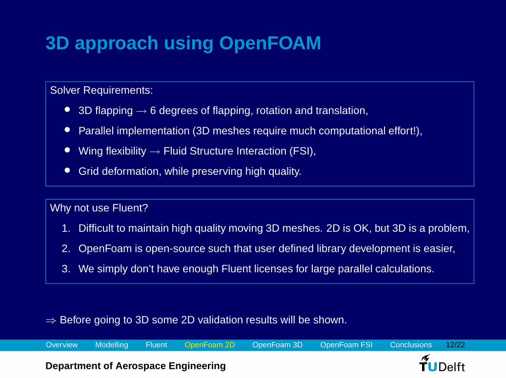
Solver Requirements:
• 3D flapping → 6 degrees of flapping, rotation and translation,
• Parallel implementation (3D meshes require much computational effort!),
• Wing flexibility → Fluid Structure Interaction (FSI),
• Grid deformation, while preserving high quality.
Why not use Fluent?
1. Difficult to maintain high quality moving 3D meshes. 2D is OK, but 3D is a problem,
2. OpenFoam is open-source such that user defined library development is easier,
3. We simply don’t have enough Fluent licenses for large parallel calculations.
⇒ Before going to 3D some 2D validation results will be shown.
Overview Modelling Fluent OpenFoam 2D OpenFoam 3D OpenFoam FSI Conclusions 13/22
Department of Aerospace Engineering
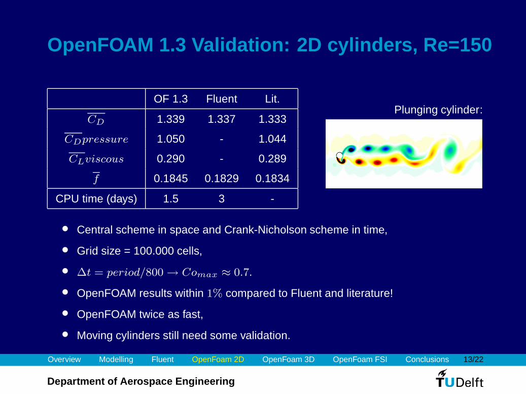
OpenFOAM 1.3 Validation: 2D cylinders, Re=150
OF 1.3 Fluent Lit.
CD 1.339 1.337 1.333
CDpressure 1.050 - 1.044
CLviscous 0.290 - 0.289
f 0.1845 0.1829 0.1834
CPU time (days) 1.5 3 -
Plunging cylinder:
• Central scheme in space and Crank-Nicholson scheme in time,
• Grid size = 100.000 cells,
• ∆t = period/800 → Comax ≈ 0.7.
• OpenFOAM results within 1% compared to Fluent and literature!
• OpenFOAM twice as fast,
• Moving cylinders still need some validation.
Overview Modelling Fluent OpenFoam 2D OpenFoam 3D OpenFoam FSI Conclusions 14/22
Department of Aerospace Engineering
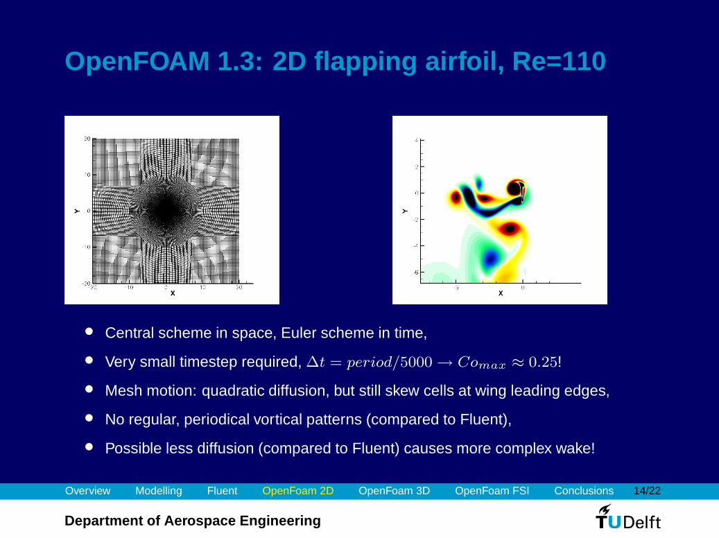
OpenFOAM 1.3: 2D flapping airfoil, Re=110
• Central scheme in space, Euler scheme in time,
• Very small timestep required, ∆t = period/5000 → Comax ≈ 0.25!
• Mesh motion: quadratic diffusion, but still skew cells at wing leading edges,
• No regular, periodical vortical patterns (compared to Fluent),
• Possible less diffusion (compared to Fluent) causes more complex wake!
Overview Modelling Fluent OpenFoam 2D OpenFoam 3D OpenFoam FSI Conclusions 15/22
Department of Aerospace Engineering
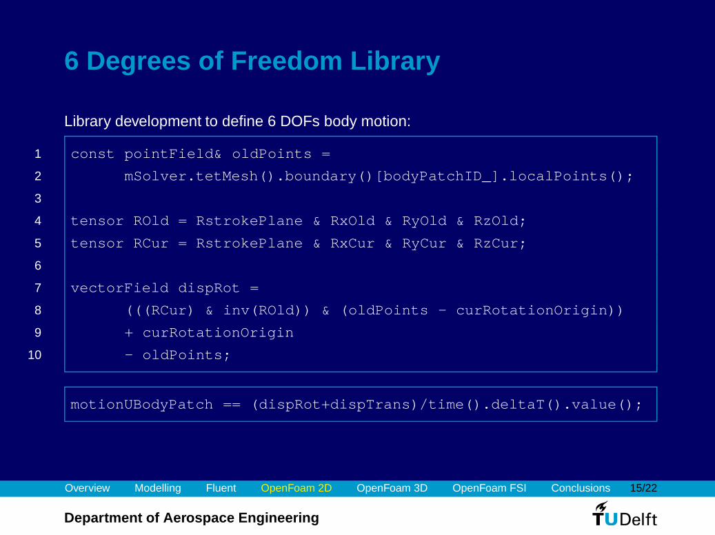
6 Degrees of Freedom Library
Library development to define 6 DOFs body motion:
1 const pointField& oldPoints =
2 mSolver.tetMesh().boundary()[bodyPatchID_].localPoints();
3
4 tensor ROld = RstrokePlane & RxOld & RyOld & RzOld;
5 tensor RCur = RstrokePlane & RxCur & RyCur & RzCur;
6
7 vectorField dispRot =
8 (((RCur) & inv(ROld)) & (oldPoints - curRotationOrigin))
9 + curRotationOrigin
10 - oldPoints;
motionUBodyPatch == (dispRot+dispTrans)/time().deltaT().value();
Overview Modelling Fluent OpenFoam 2D OpenFoam 3D OpenFoam FSI Conclusions 16/22
Department of Aerospace Engineering
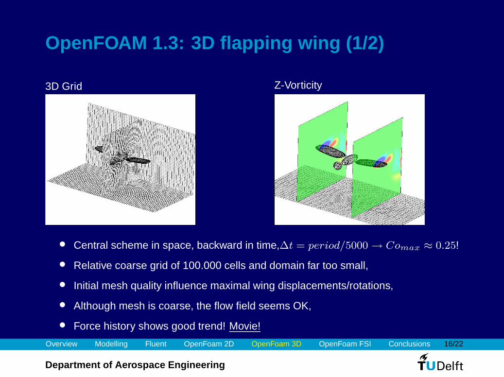
OpenFOAM 1.3: 3D flapping wing (1/2)
3D Grid Z-Vorticity
• Central scheme in space, backward in time,∆t = period/5000 → Comax ≈ 0.25!
• Relative coarse grid of 100.000 cells and domain far too small,
• Initial mesh quality influence maximal wing displacements/rotations,
• Although mesh is coarse, the flow field seems OK,
• Force history shows good trend! Movie!
Overview Modelling Fluent OpenFoam 2D OpenFoam 3D OpenFoam FSI Conclusions 17/22
Department of Aerospace Engineering
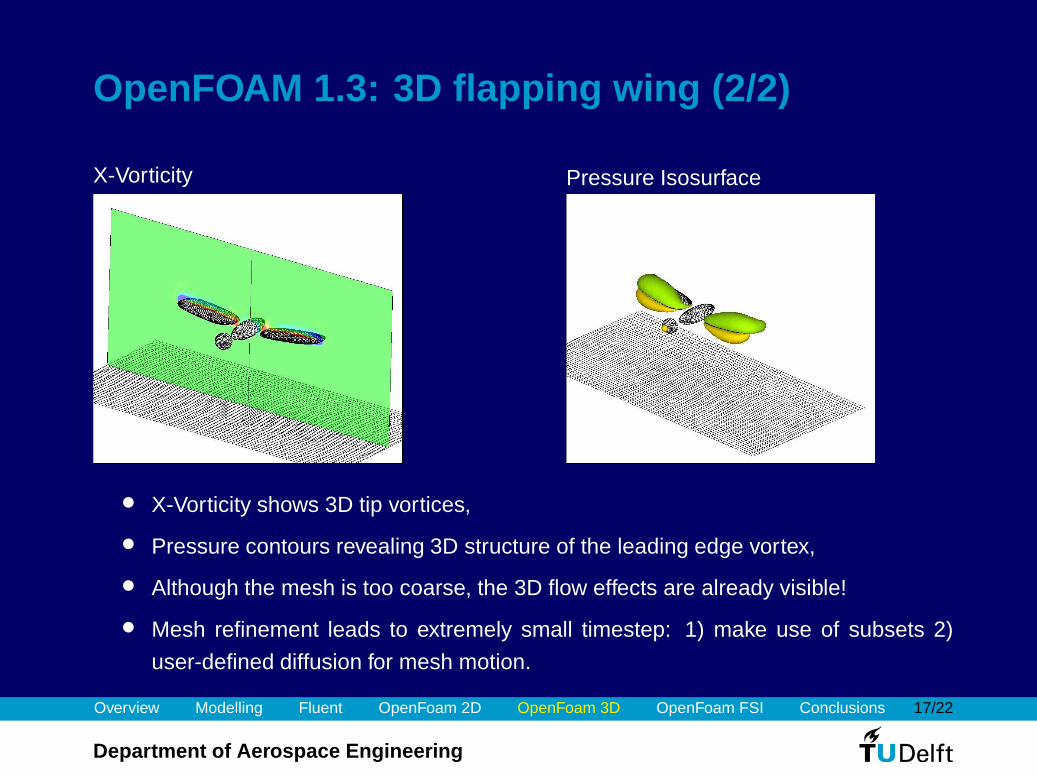
OpenFOAM 1.3: 3D flapping wing (2/2)
X-Vorticity Pressure Isosurface
• X-Vorticity shows 3D tip vortices,
• Pressure contours revealing 3D structure of the leading edge vortex,
• Although the mesh is too coarse, the 3D flow effects are already visible!
• Mesh refinement leads to extremely small timestep: 1) make use of subsets 2)
user-defined diffusion for mesh motion.
Overview Modelling Fluent OpenFoam 2D OpenFoam 3D OpenFoam FSI Conclusions 18/22
Department of Aerospace Engineering
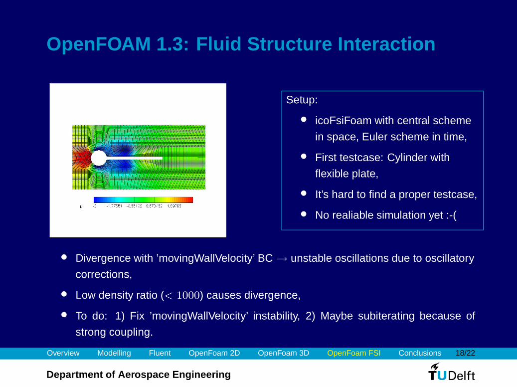
OpenFOAM 1.3: Fluid Structure Interaction
Setup:
• icoFsiFoam with central scheme
in space, Euler scheme in time,
• First testcase: Cylinder with
flexible plate,
• It’s hard to find a proper testcase,
• No realiable simulation yet :-(
• Divergence with ’movingWallVelocity’ BC → unstable oscillations due to oscillatory
corrections,
• Low density ratio (< 1000) causes divergence,
• To do: 1) Fix ’movingWallVelocity’ instability, 2) Maybe subiterating because of
strong coupling.
Overview Modelling Fluent OpenFoam 2D OpenFoam 3D OpenFoam FSI Conclusions 19/22
Department of Aerospace Engineering
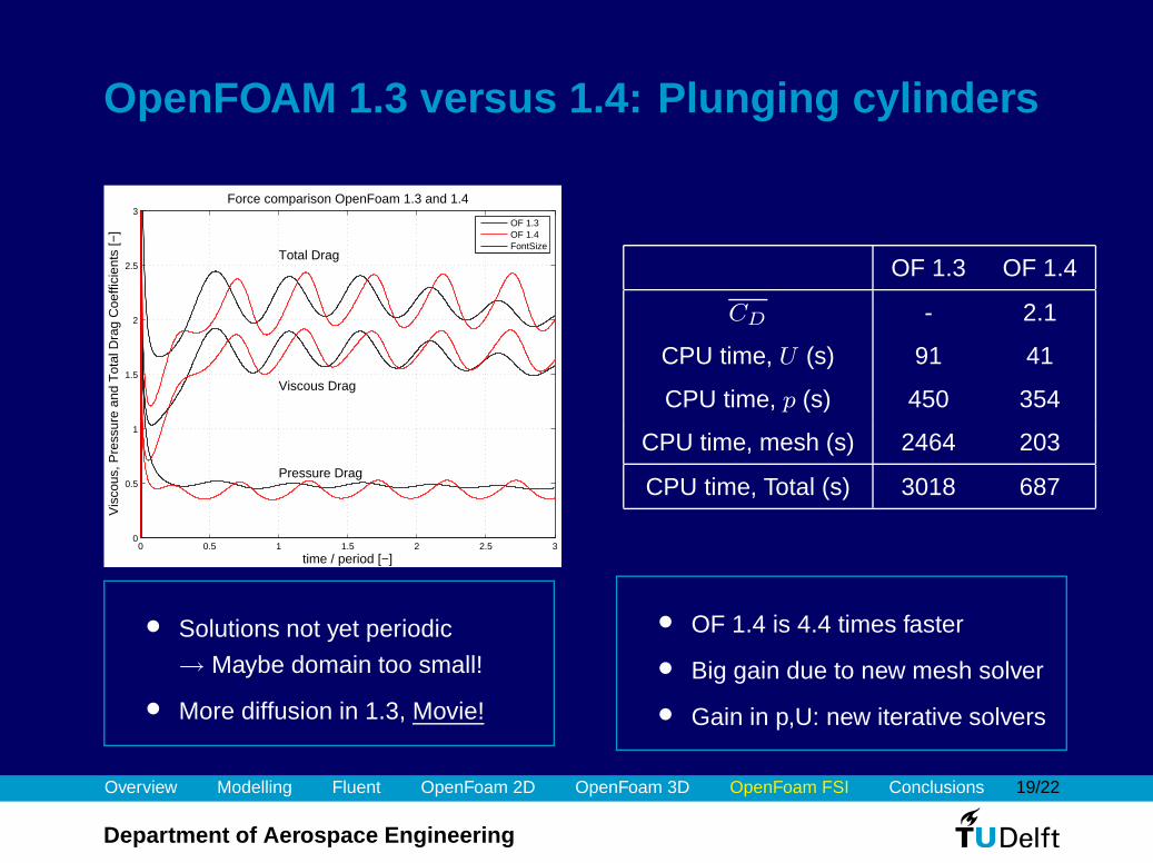
OpenFOAM 1.3 versus 1.4: Plunging cylinders
0 0.5 1 1.5 2 2.5 30
0.5
1
1.5
2
2.5
3
time / period [−]
Vis
cous
, Pre
ssur
e an
d T
otal
Dra
g C
oeffi
cien
ts [−
]
Force comparison OpenFoam 1.3 and 1.4
Pressure Drag
Viscous Drag
Total Drag
OF 1.3OF 1.4FontSize
OF 1.3 OF 1.4
CD - 2.1
CPU time, U (s) 91 41
CPU time, p (s) 450 354
CPU time, mesh (s) 2464 203
CPU time, Total (s) 3018 687
• Solutions not yet periodic
→ Maybe domain too small!
• More diffusion in 1.3, Movie!
• OF 1.4 is 4.4 times faster
• Big gain due to new mesh solver
• Gain in p,U: new iterative solvers
Overview Modelling Fluent OpenFoam 2D OpenFoam 3D OpenFoam FSI Conclusions 20/22
Department of Aerospace Engineering
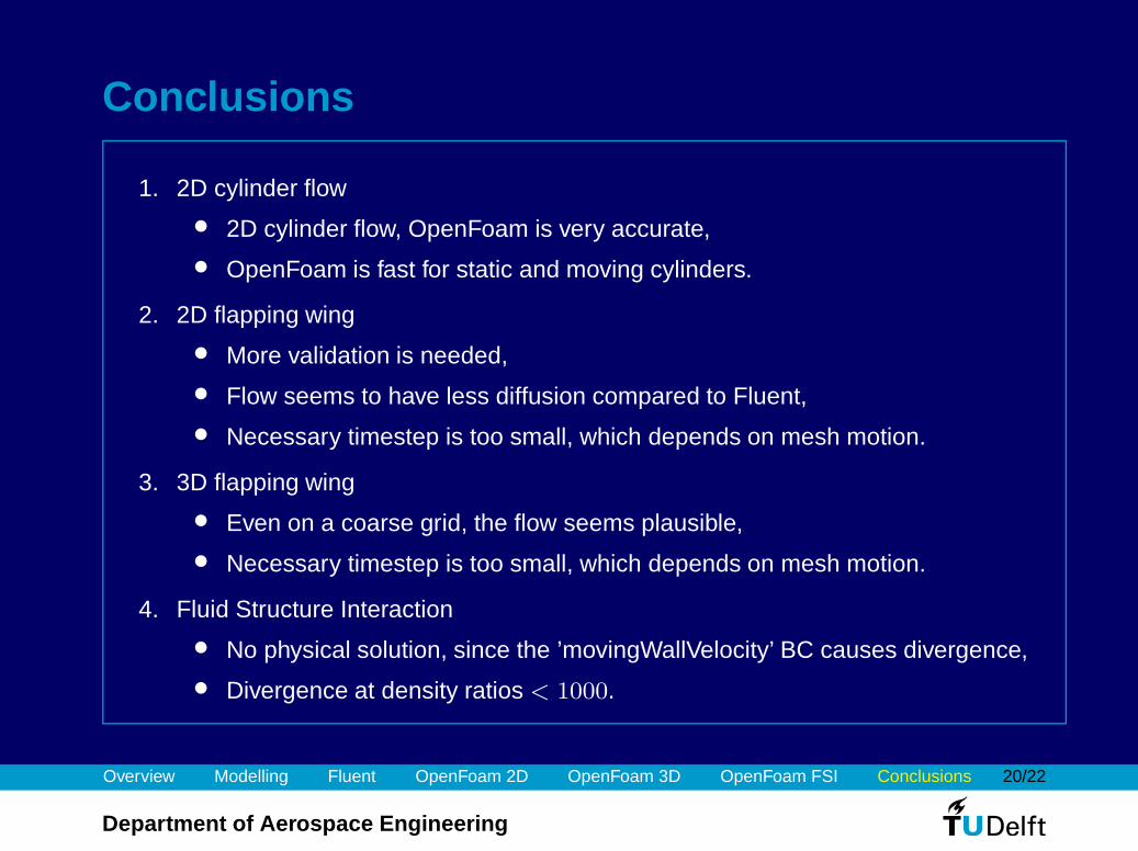
Conclusions
1. 2D cylinder flow
• 2D cylinder flow, OpenFoam is very accurate,
• OpenFoam is fast for static and moving cylinders.
2. 2D flapping wing
• More validation is needed,
• Flow seems to have less diffusion compared to Fluent,
• Necessary timestep is too small, which depends on mesh motion.
3. 3D flapping wing
• Even on a coarse grid, the flow seems plausible,
• Necessary timestep is too small, which depends on mesh motion.
4. Fluid Structure Interaction
• No physical solution, since the ’movingWallVelocity’ BC causes divergence,
• Divergence at density ratios < 1000.
Overview Modelling Fluent OpenFoam 2D OpenFoam 3D OpenFoam FSI Conclusions 21/22
Department of Aerospace Engineering
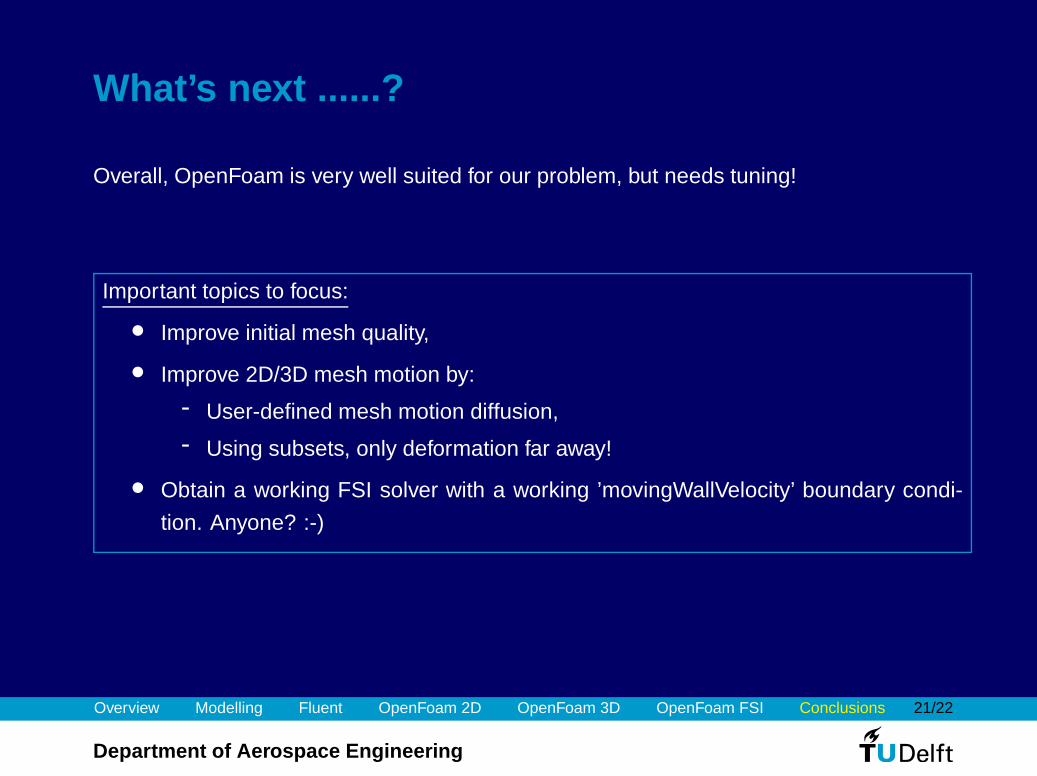
What’s next ......?
Overall, OpenFoam is very well suited for our problem, but needs tuning!
Important topics to focus:
• Improve initial mesh quality,
• Improve 2D/3D mesh motion by:
- User-defined mesh motion diffusion,
- Using subsets, only deformation far away!
• Obtain a working FSI solver with a working ’movingWallVelocity’ boundary condi-
tion. Anyone? :-)

Overview Modelling Fluent OpenFoam 2D OpenFoam 3D OpenFoam FSI Conclusions 22/22
Department of Aerospace Engineering
Thanks for your attention!
Questions or Remarks?
Overview Modelling Fluent OpenFoam 2D OpenFoam 3D OpenFoam FSI Conclusions 23/22
Department of Aerospace Engineering
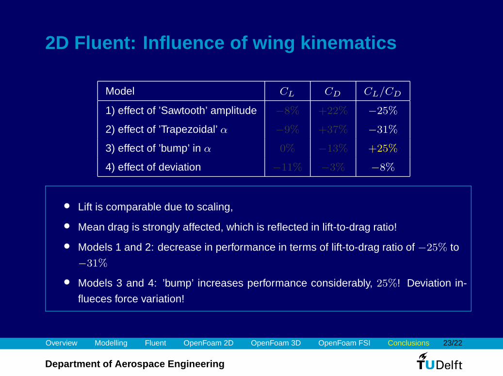
2D Fluent: Influence of wing kinematics
Model CL CD CL/CD
1) effect of ’Sawtooth’ amplitude −8% +22% −25%
2) effect of ’Trapezoidal’ α −9% +37% −31%
3) effect of ’bump’ in α 0% −13% +25%
4) effect of deviation −11% −3% −8%
• Lift is comparable due to scaling,
• Mean drag is strongly affected, which is reflected in lift-to-drag ratio!
• Models 1 and 2: decrease in performance in terms of lift-to-drag ratio of −25% to
−31%
• Models 3 and 4: ’bump’ increases performance considerably, 25%! Deviation in-
flueces force variation!


![Experimental analysis of submerged flapping foils ... · principles of flapping foil wave propulsion [1,2,3,4]. MOST (Autonomous Vessels) Ltd have developed a long range endurance](https://img.pdfslide.us/doc/110x75/5f061c6a7e708231d4165844/experimental-analysis-of-submerged-iapping-foils-principles-of-iapping-foil.jpg)