Embed Size (px)
Citation preview
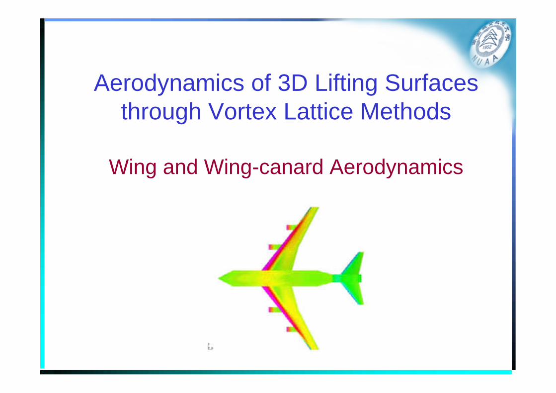
Aerodynamics of 3D Lifting Surfacesthrough Vortex Lattice Methods
Wing and Wing-canard Aerodynamics
Outline• Basic Concepts
– Boundary conditions on the mean surface
– Vortex Theorems, Biot-Savart Law
– The Horseshoe Vortex
– Selection of Control Point and Vortex Location
• The Classical Vortex Lattice Method
• Two implementations of the VLM– VLM program
– TORNADO
• Application Examples of VLM
• Insights into wing and wing-canard aerodynamics
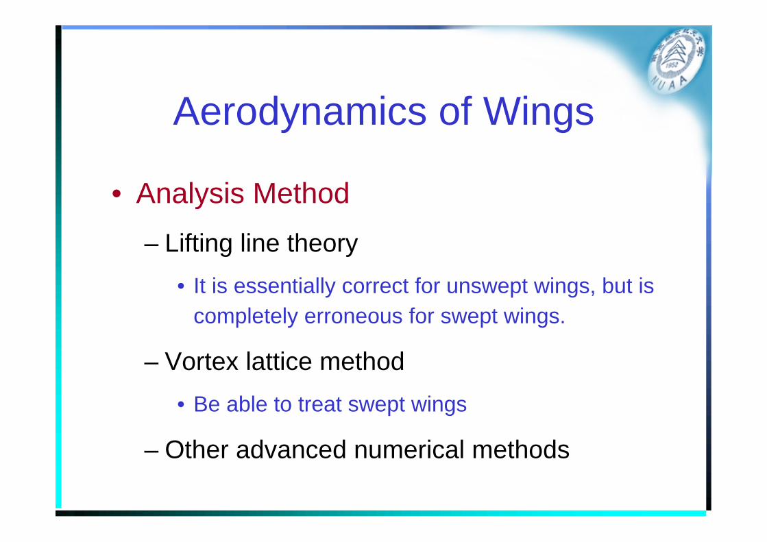
Aerodynamics of Wings
• Analysis Method
– Lifting line theory• It is essentially correct for unswept wings, but is
completely erroneous for swept wings.
– Vortex lattice method• Be able to treat swept wings
– Other advanced numerical methods
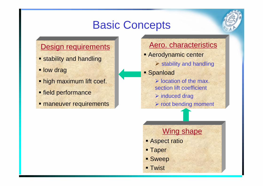
Basic Concepts
Design requirementsstability and handling
low drag
high maximum lift coef.
field performance
maneuver requirements
Aero. characteristicsAerodynamic center
stability and handlingSpanload
location of the max. section lift coefficient
induced dragroot bending moment
Wing shapeAspect ratioTaperSweep Twist
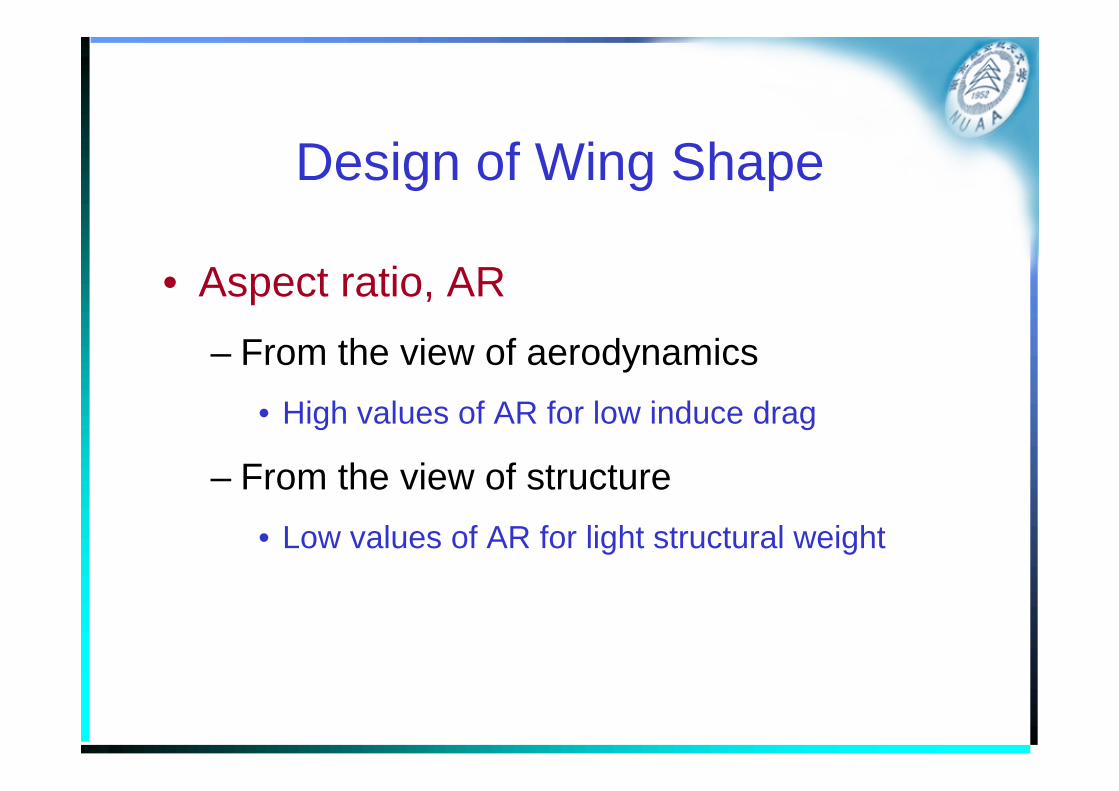
Design of Wing Shape
• Aspect ratio, AR– From the view of aerodynamics
• High values of AR for low induce drag
– From the view of structure• Low values of AR for light structural weight
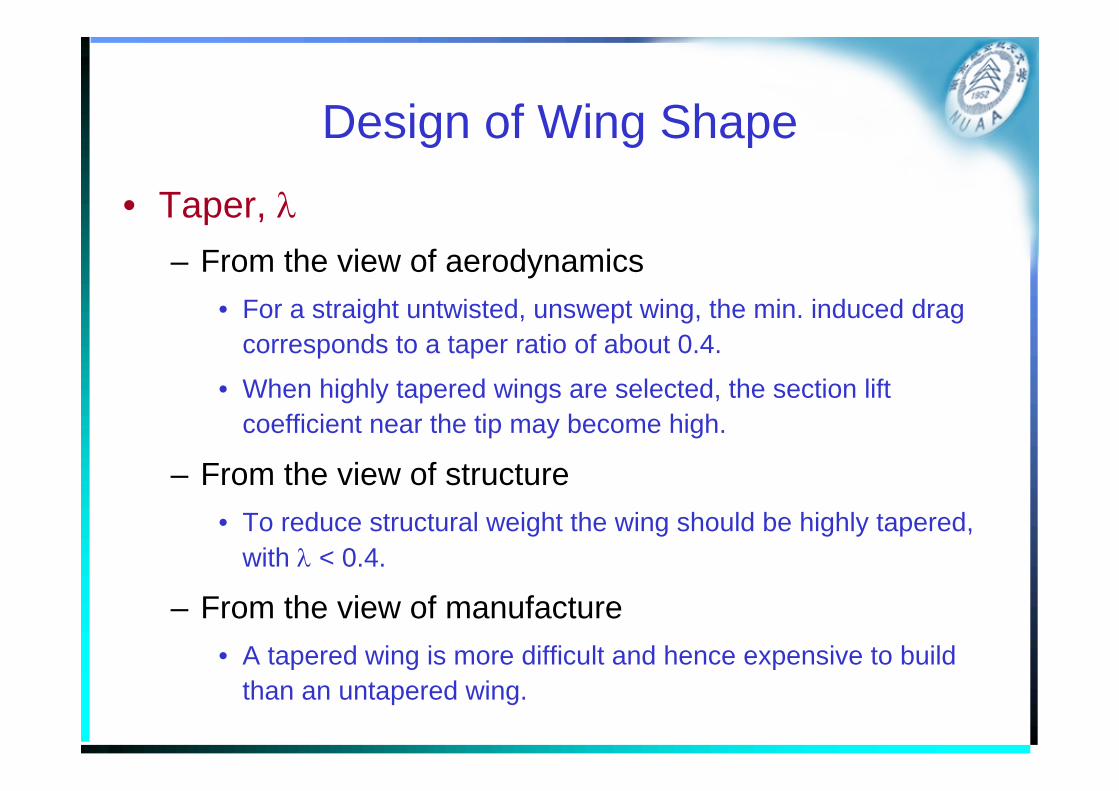
Design of Wing Shape• Taper, λ
– From the view of aerodynamics• For a straight untwisted, unswept wing, the min. induced drag
corresponds to a taper ratio of about 0.4.
• When highly tapered wings are selected, the section lift coefficient near the tip may become high.
– From the view of structure• To reduce structural weight the wing should be highly tapered,
with λ < 0.4.
– From the view of manufacture• A tapered wing is more difficult and hence expensive to build
than an untapered wing.
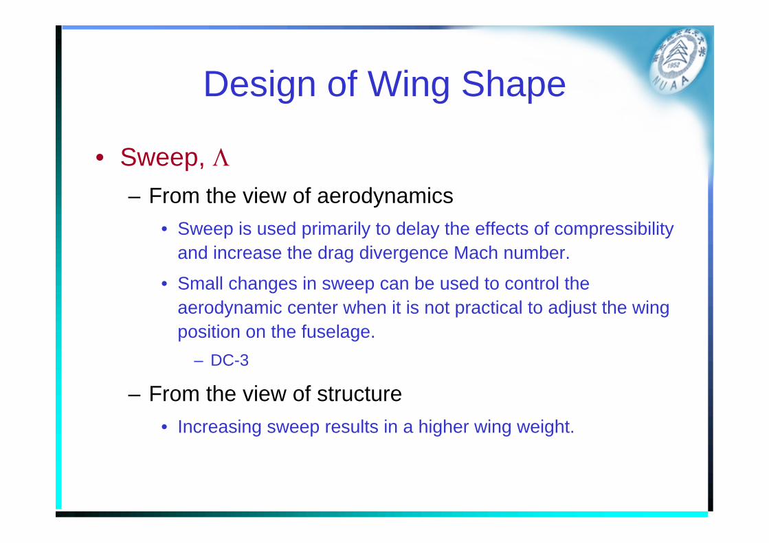
Design of Wing Shape
• Sweep, Λ– From the view of aerodynamics
• Sweep is used primarily to delay the effects of compressibility and increase the drag divergence Mach number.
• Small changes in sweep can be used to control the aerodynamic center when it is not practical to adjust the wing position on the fuselage.
– DC-3
– From the view of structure• Increasing sweep results in a higher wing weight.
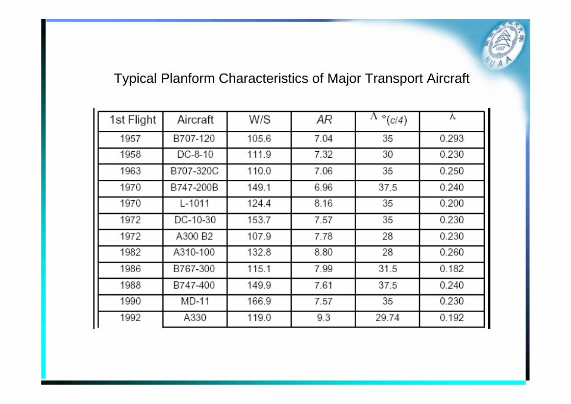
Typical Planform Characteristics of Major Transport Aircraft
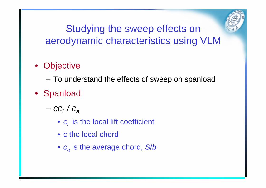
Studying the sweep effects on aerodynamic characteristics using VLM
• Objective– To understand the effects of sweep on spanload
• Spanload
– ccl / ca
• cl is the local lift coefficient
• c the local chord
• ca is the average chord, S/b
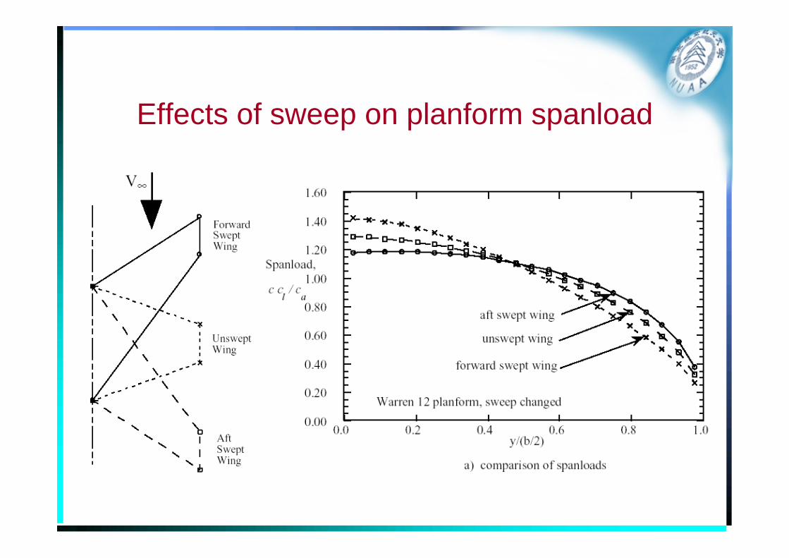
Effects of sweep on planform spanload
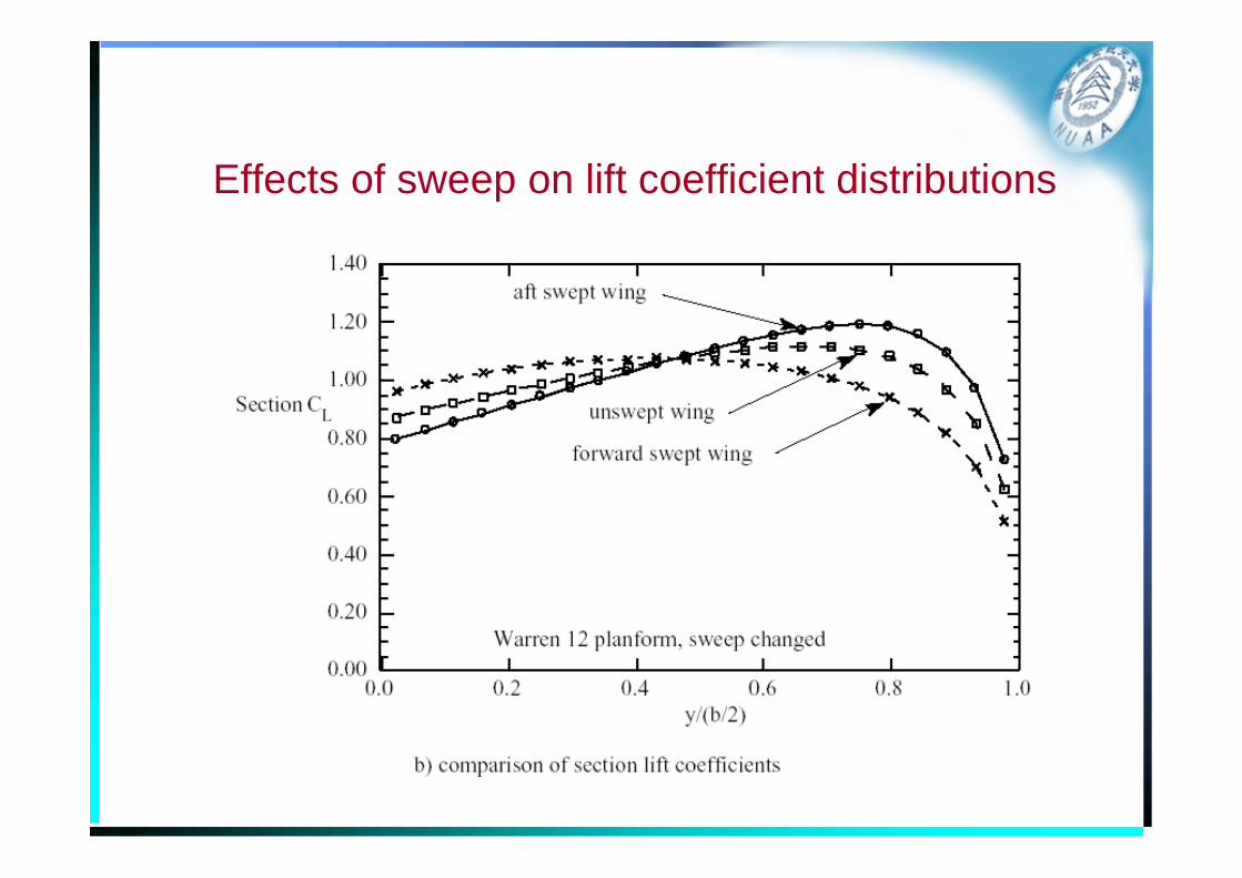
Effects of sweep on lift coefficient distributions
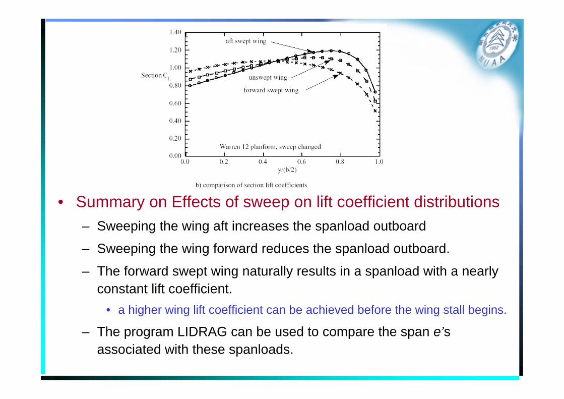
• Summary on Effects of sweep on lift coefficient distributions– Sweeping the wing aft increases the spanload outboard
– Sweeping the wing forward reduces the spanload outboard.
– The forward swept wing naturally results in a spanload with a nearly constant lift coefficient.
• a higher wing lift coefficient can be achieved before the wing stall begins.
– The program LIDRAG can be used to compare the span e’s associated with these spanloads.
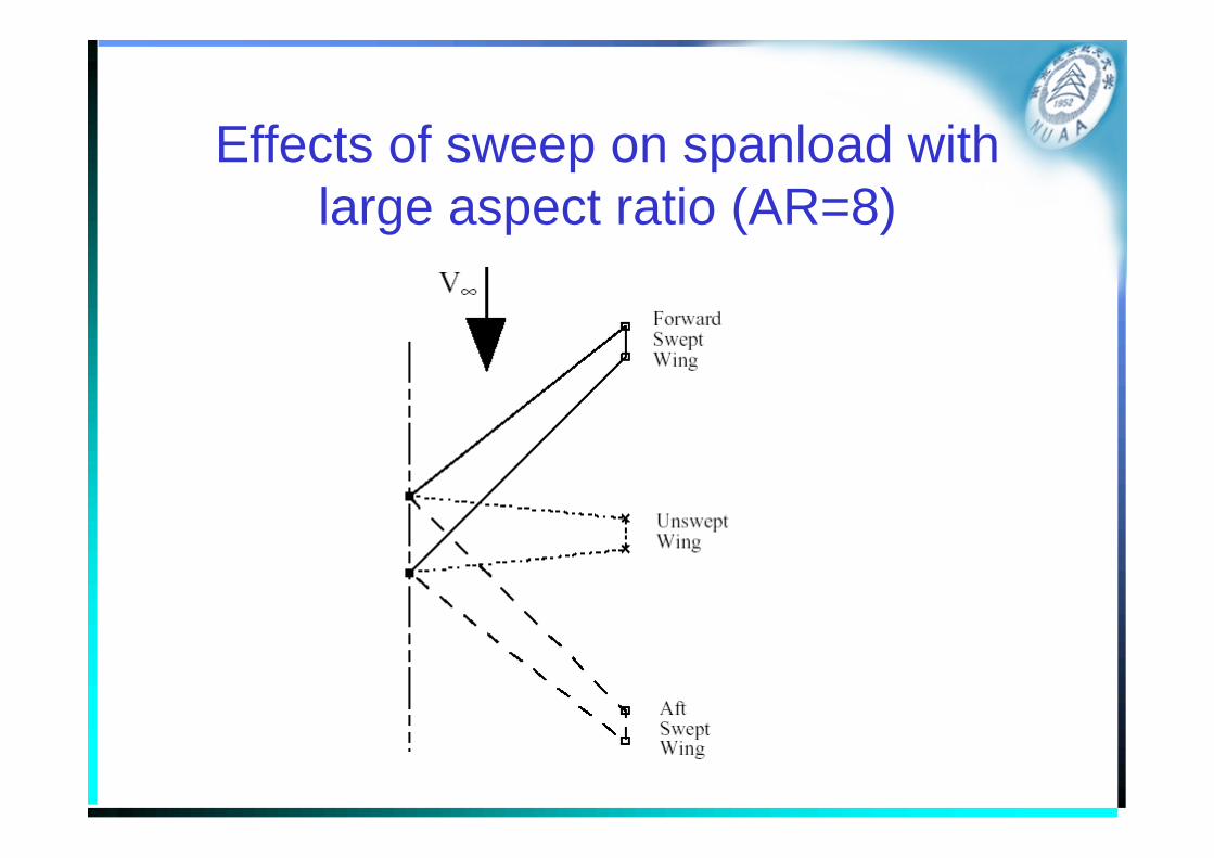
Effects of sweep on spanload with large aspect ratio (AR=8)
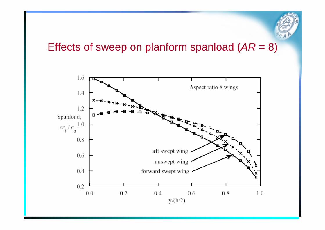
Effects of sweep on planform spanload (AR = 8)
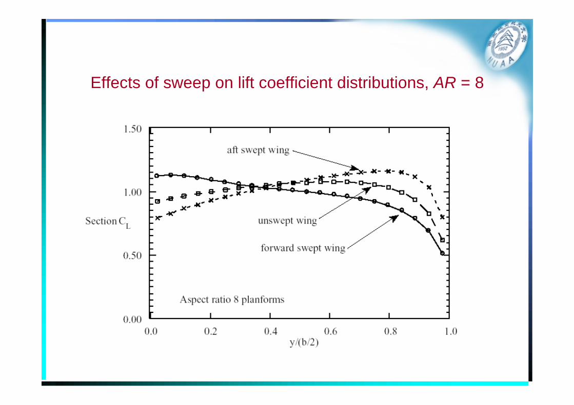
Effects of sweep on lift coefficient distributions, AR = 8
• Comments on results for the wing with large aspect ratio – These results are similar to the previous results.
– The trends observed are in fact exaggerated at the higher aspect ratio.
– Because of the high section lift coefficient near the tip, aft swept wings tend to stall near the tip first.
– “pitchup”• Since the lift at the tip is generated well aft, the pitching
moment characteristics change when the this stall occurs.
• With the inboard wing continuing to lift, a large positive increase in pitching moment occurs when the wingtip stalls.
• Difficult to control, resulting in unsafe flight conditions.
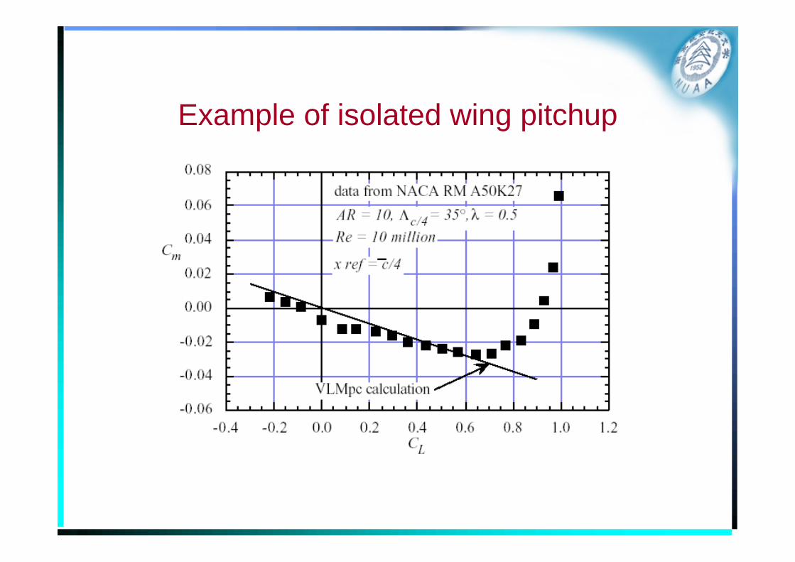
Example of isolated wing pitchup
Design of Wing Shape
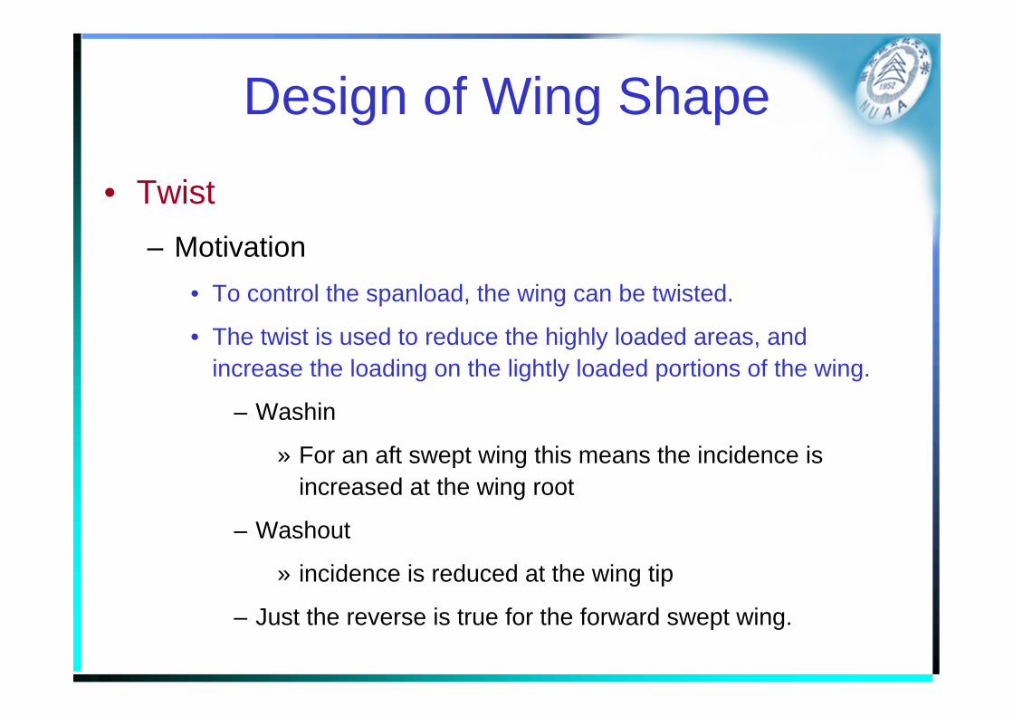
• Twist– Motivation
• To control the spanload, the wing can be twisted.
• The twist is used to reduce the highly loaded areas, and increase the loading on the lightly loaded portions of the wing.
– Washin
» For an aft swept wing this means the incidence is increased at the wing root
– Washout
» incidence is reduced at the wing tip
– Just the reverse is true for the forward swept wing.
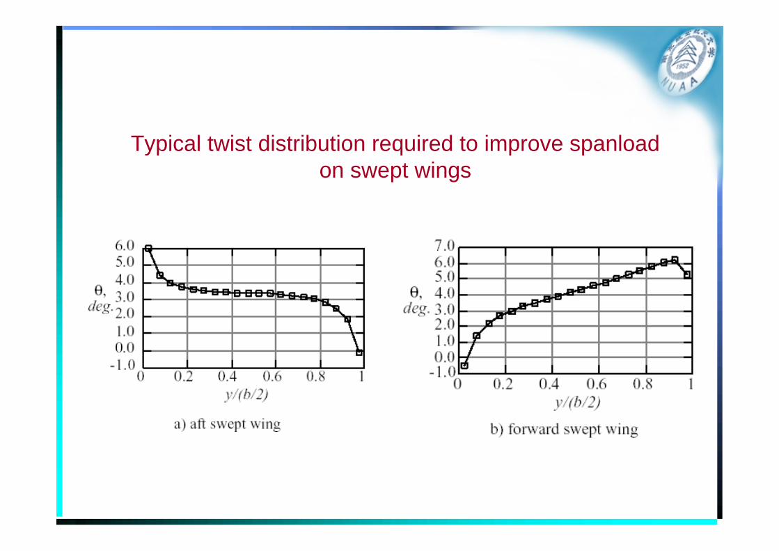
Typical twist distribution required to improve spanloadon swept wings
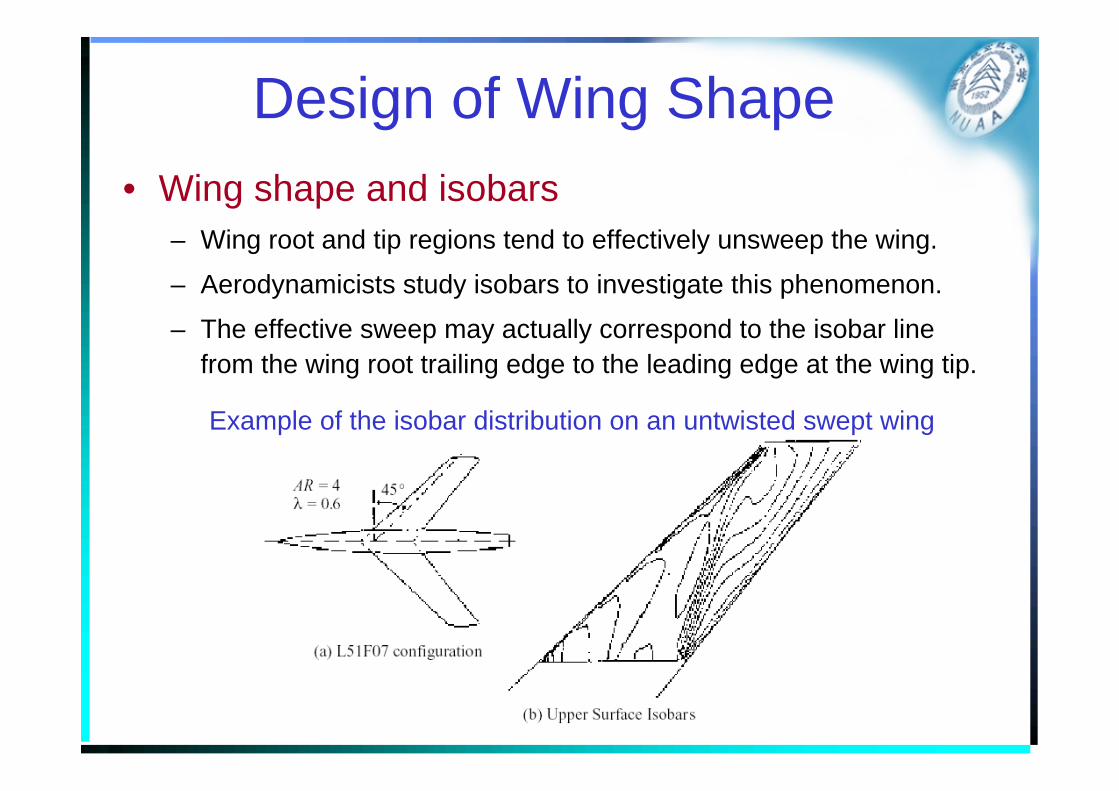
Design of Wing Shape• Wing shape and isobars
– Wing root and tip regions tend to effectively unsweep the wing.
– Aerodynamicists study isobars to investigate this phenomenon.
– The effective sweep may actually correspond to the isobar line from the wing root trailing edge to the leading edge at the wing tip.
Example of the isobar distribution on an untwisted swept wing
Design of Wing Shape
• Wing shape and isobars– To increase the isobar sweep, in addition to geometric
sweep and twist, the camber surface and thickness are typically adjusted to move the isobars forward at the wing root and aft at the wing tip.
– This is a key part of the aerodynamic wing design job, regardless of the computational methodology used to obtain the predicted ispbar
– A code “LamDes” can be used to design camber and twist.
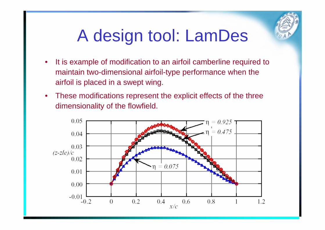
A design tool: LamDes• It is example of modification to an airfoil camberline required to
maintain two-dimensional airfoil-type performance when the airfoil is placed in a swept wing.
• These modifications represent the explicit effects of the three dimensionality of the flowfield.
Design of Wing Shape
• Yehudi flap– From the view of structure
• To provide structure to attach the landing gear at the proper location.
– From the view of aerodynmics• The additional chord lowers the section lift coefficient at the
root, where wing-fuselage interference can be a problem, and the lower required section lift makes the design job easier.
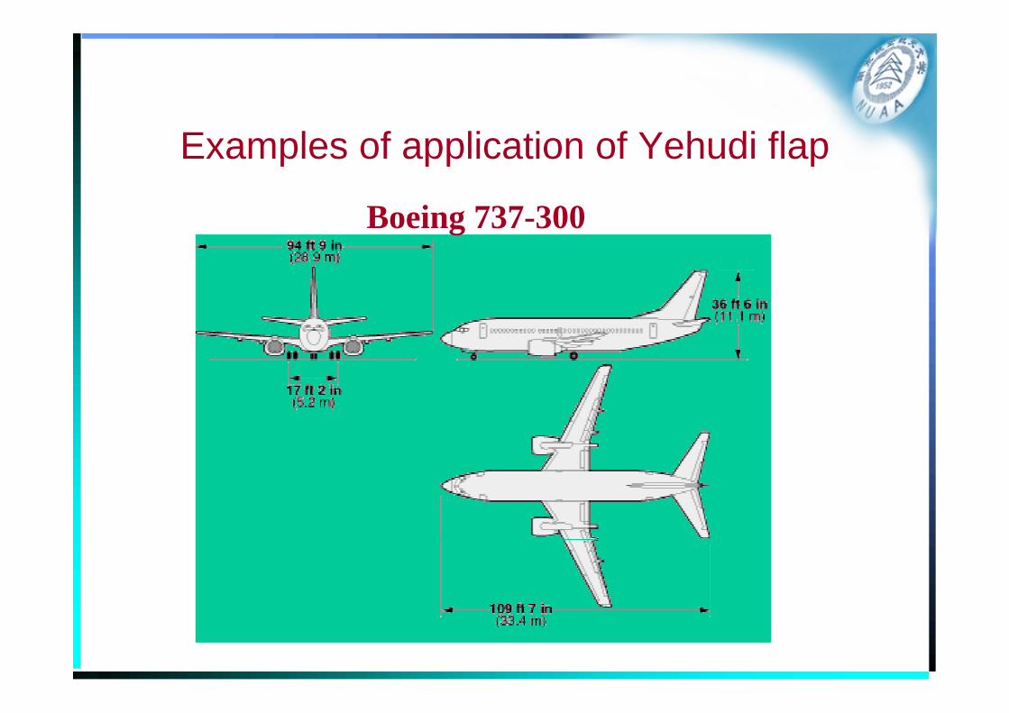
Examples of application of Yehudi flap
Boeing 737-300
Wing/Tail Aerodynamics• The important issues of aerodynamic development for
swept wing and wing-tail configuration are:– Pitch Moment characteristics
• “Pitch-up” should be avoided
– Deep stall for wing/tail• An undesirable equilibrium condition, which could result in the
vehicle actually trying to “fly” at a large angle of attack (43°).
• If adequate control power is not available, it may even be difficult to dislodge the vehicle from this condition, which is commonly known as a deep or hung stall.
• This will result in a rapid loss of altitude due to the very high drag.
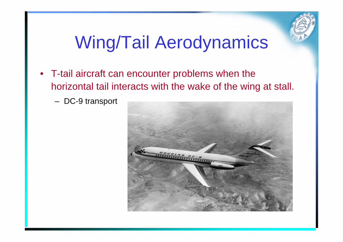
Wing/Tail Aerodynamics• T-tail aircraft can encounter problems when the
horizontal tail interacts with the wake of the wing at stall.– DC-9 transport
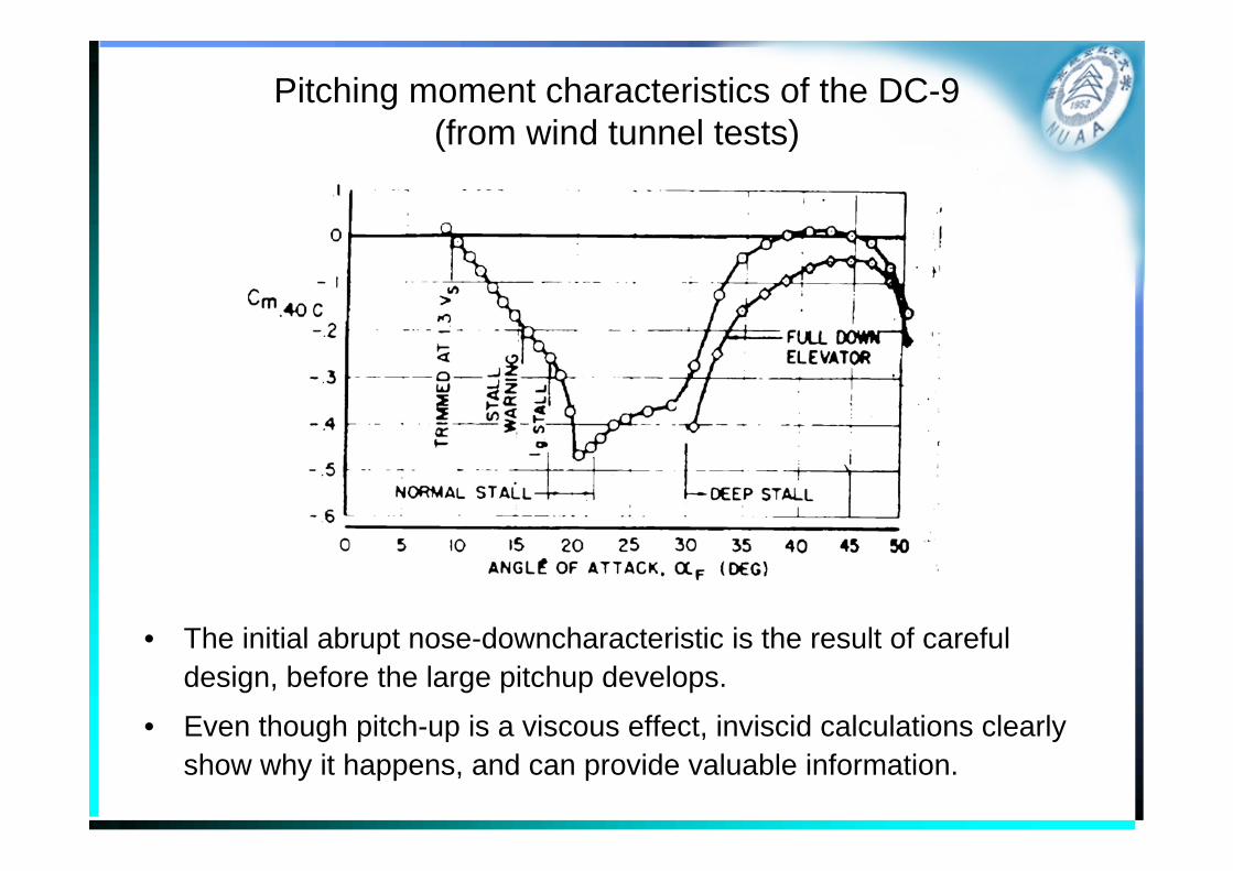
Pitching moment characteristics of the DC-9(from wind tunnel tests)
• The initial abrupt nose-downcharacteristic is the result of careful design, before the large pitchup develops.
• Even though pitch-up is a viscous effect, inviscid calculations clearly show why it happens, and can provide valuable information.
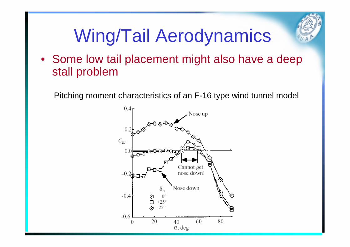
Wing/Tail Aerodynamics• Some low tail placement might also have a deep
stall problem
Pitching moment characteristics of an F-16 type wind tunnel model
Wing-canard aerodynamics
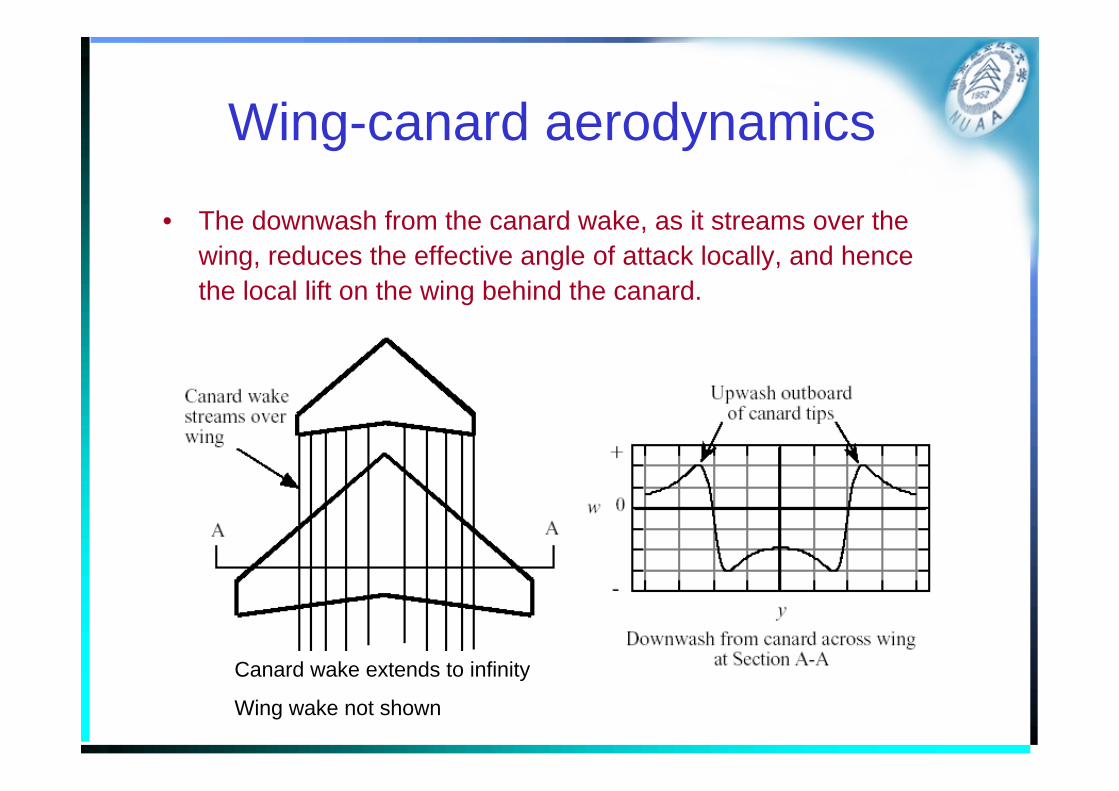
• The downwash from the canard wake, as it streams over the wing, reduces the effective angle of attack locally, and hence the local lift on the wing behind the canard.
Canard wake extends to infinity
Wing wake not shown
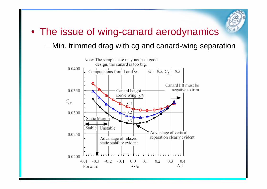
• The issue of wing-canard aerodynamics– Min. trimmed drag with cg and canard-wing separation
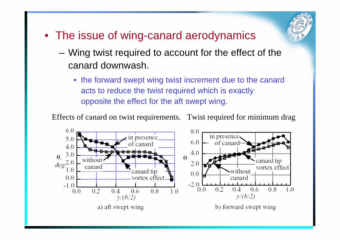
• The issue of wing-canard aerodynamics– Wing twist required to account for the effect of the
canard downwash.• the forward swept wing twist increment due to the canard
acts to reduce the twist required which is exactly opposite the effect for the aft swept wing.
Effects of canard on twist requirements. Twist required for minimum drag
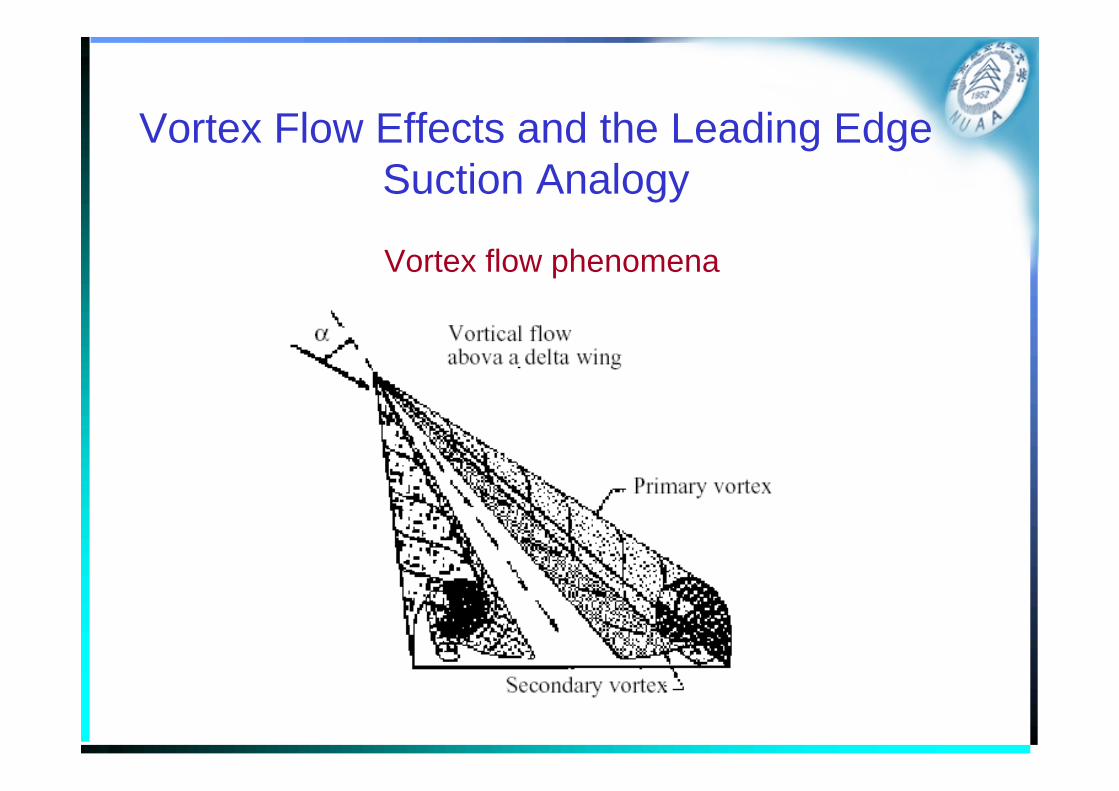
Vortex Flow Effects and the Leading Edge Suction Analogy
Vortex flow phenomena
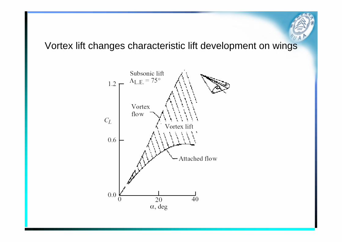
Vortex lift changes characteristic lift development on wings
• For highly swept wings at even moderate angles of attack, the classical attached flow/trailing edge Kuttacondition flow model is wrong.
• Instead of the flow remaining attached on the wing and leaving the trailing edge smoothly, the flow separates at the leading edge, forming a well defined vortex.
• This vortex plays an important role in the design of highly swept, or “slender wing” aircraft.
Importance of Vortex Flow
• Slender wings have very low attached flow lift curve slopes, and without the additional vortex lift it would be impractical to build configurations with low aspect ratio wings.
– Vortex lift made the Concorde possible
• Another feature
– The high angle of attack at which maximum lift occurs.
– Typically a very mild lift loss past maximum lift.
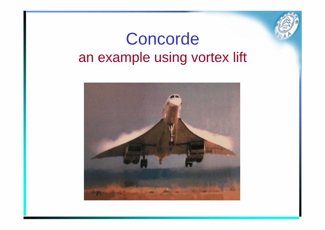
Concordean example using vortex lift
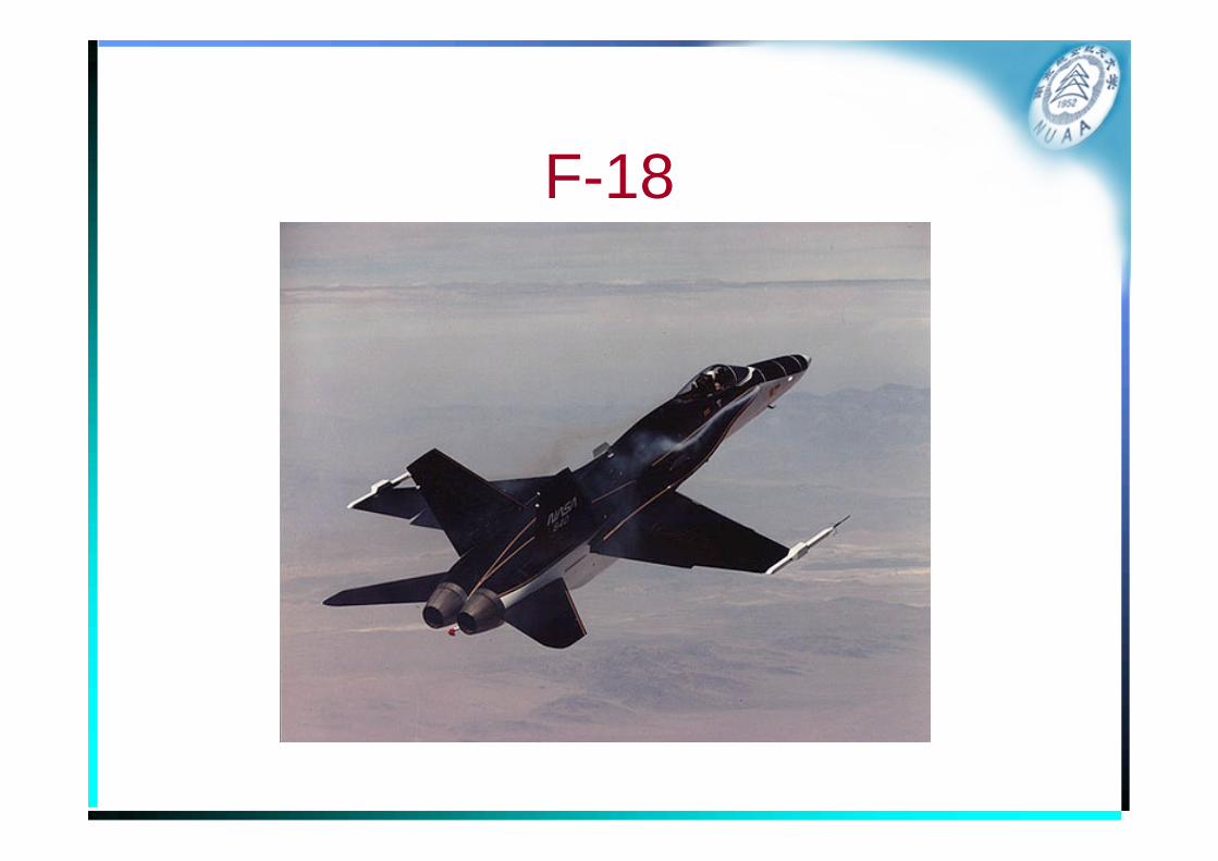
F-18
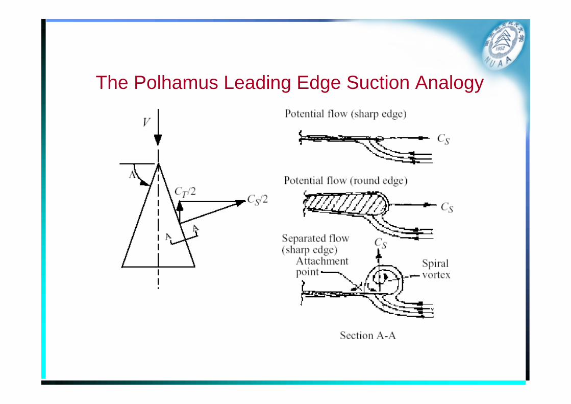
The Polhamus Leading Edge Suction Analogy
• Code– The Lamar vortex lattice code (VLMpc) optionally
includes a fully developed suction analogy based on Polhamus ideas, with extensions to treat side edge suction by John Lamar also included.
• Vortex Flow Aerodynamics
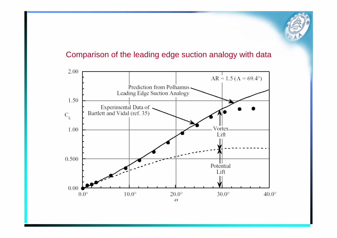
Comparison of the leading edge suction analogy with data
Alternate and Advanced VLM Methods
• Extensions to classical VLM– Wake position and rollup as part of the solution
– Improvement including the ability to predict leading edge suction
– The explicit treatment of the Kutta condition
– Improvement in convergence properties with increasing numbers of panels
• Unsteady flow extension– For the case of an assumed flat wake the extension to
harmonically oscillating surfaces was studied
• The doublet-lattice method is widely used for subsonic flutter calculations
– General unsteady flows calculations, including wake location as well as the incorporation of leading edge vortices, have been carried out.
• The resulting codes have the potential to be used to model time accurate aerodynamics of vehicles in arbitrary maneuvering flight, including the high angle of attack cases of interest in fighter aerodynamics.