Embed Size (px)
Citation preview
Surya KiranPeravali11/30/14 openPropVLM2D 1
Implementing Vortex Lattice Representation of Propeller Sections
Surya Kiran Peravali
CFD with OpenSource Software 2014
December 1, 2014
Developed for OpenFOAM-2.3.x
Chalmers University of Technology,
Gothenburg, Sweden.
11/30/14 openPropVLM2D 2
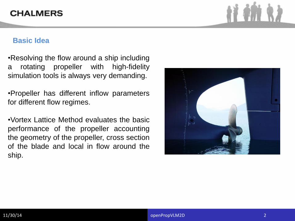
•Resolving the flow around a ship including
a rotating propeller with high-fidelity
simulation tools is always very demanding.
•Propeller has different inflow parameters
for different flow regimes.
•Vortex Lattice Method evaluates the basic
performance of the propeller accounting
the geometry of the propeller, cross section
of the blade and local in flow around the
ship.
Basic Idea
11/30/14 openPropVLM2D 3
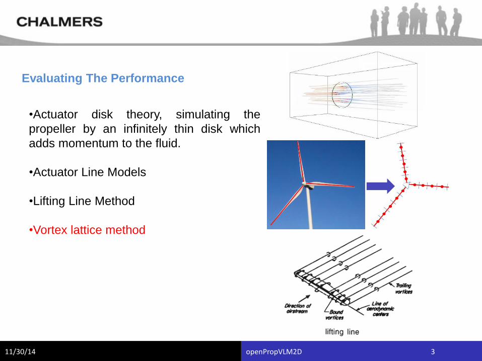
Evaluating The Performance
•Actuator disk theory, simulating the
propeller by an infinitely thin disk which
adds momentum to the fluid.
•Actuator Line Models
•Lifting Line Method
•Vortex lattice method
11/30/14 openPropVLM2D 4
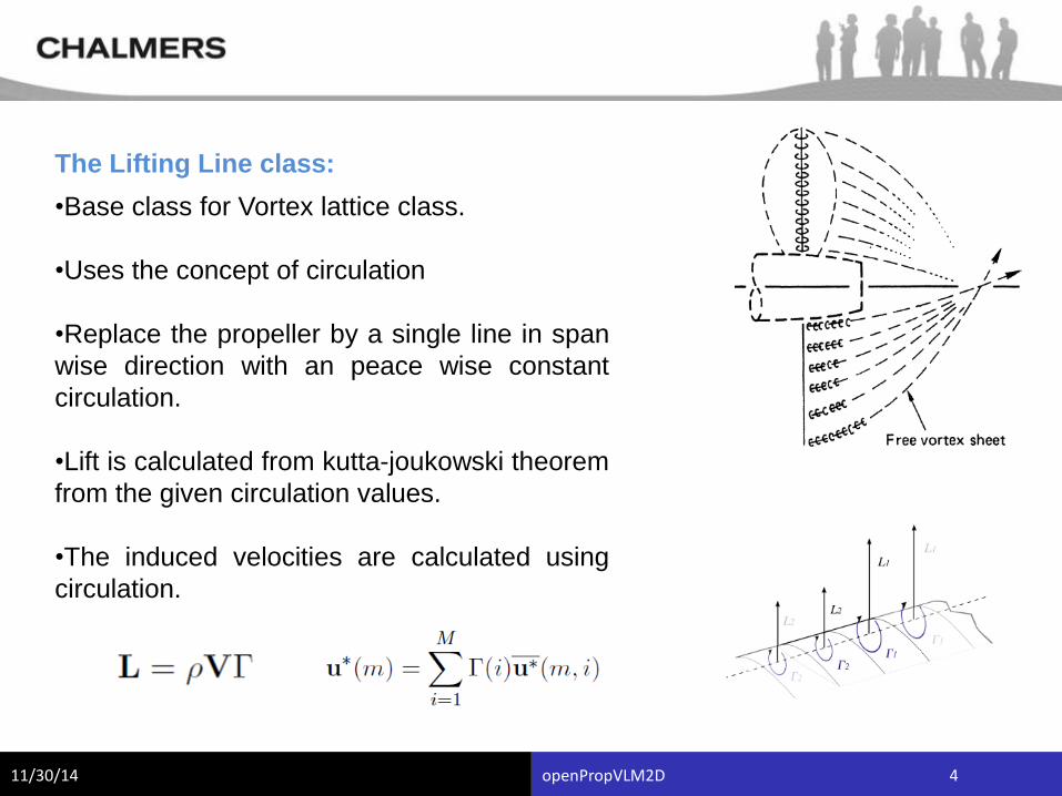
The Lifting Line class:
•Base class for Vortex lattice class.
•Uses the concept of circulation
•Replace the propeller by a single line in span
wise direction with an peace wise constant
circulation.
•Lift is calculated from kutta-joukowski theorem
from the given circulation values.
•The induced velocities are calculated using
circulation.
11/30/14 openPropVLM2D 5
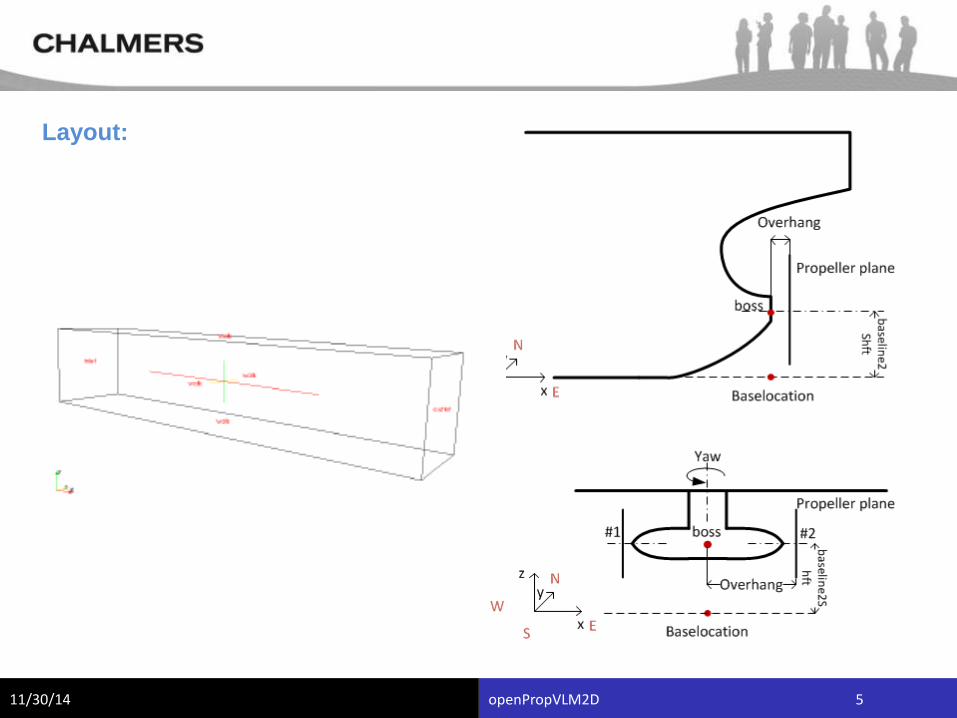
Layout:
11/30/14 openPropVLM2D 6
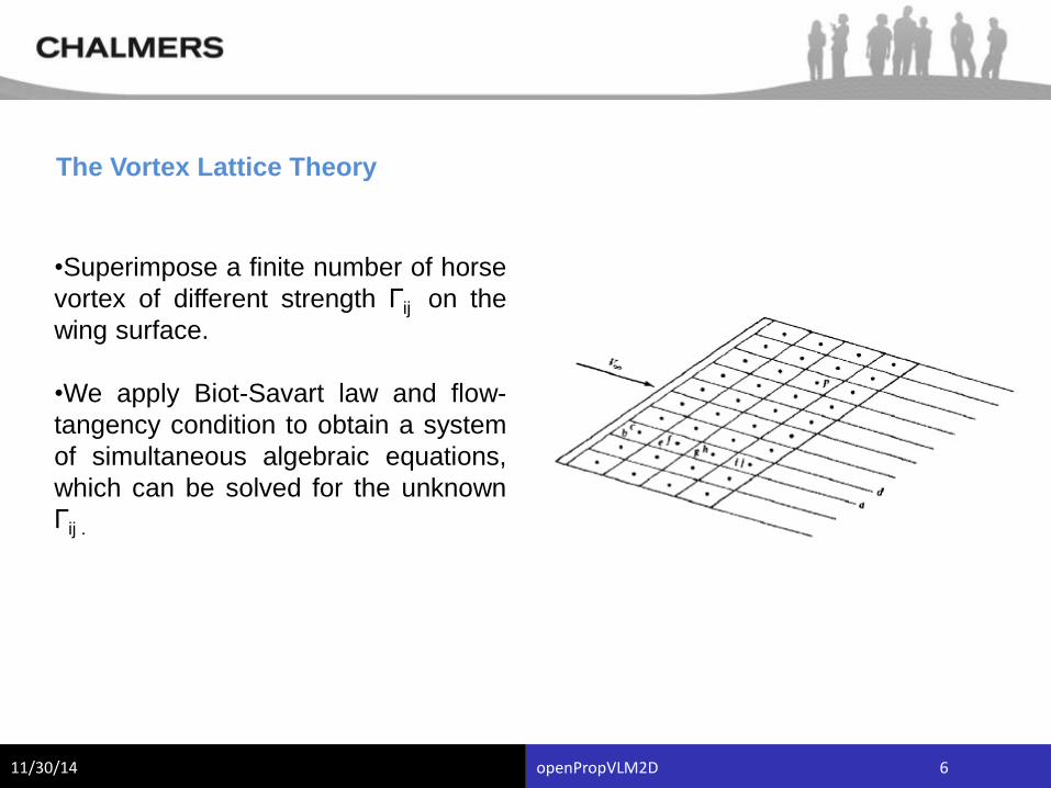
The Vortex Lattice Theory
•Superimpose a finite number of horse
vortex of different strength Гij on the
wing surface.
•We apply Biot-Savart law and flow-
tangency condition to obtain a system
of simultaneous algebraic equations,
which can be solved for the unknown
Гij .
11/30/14 openPropVLM2D 7
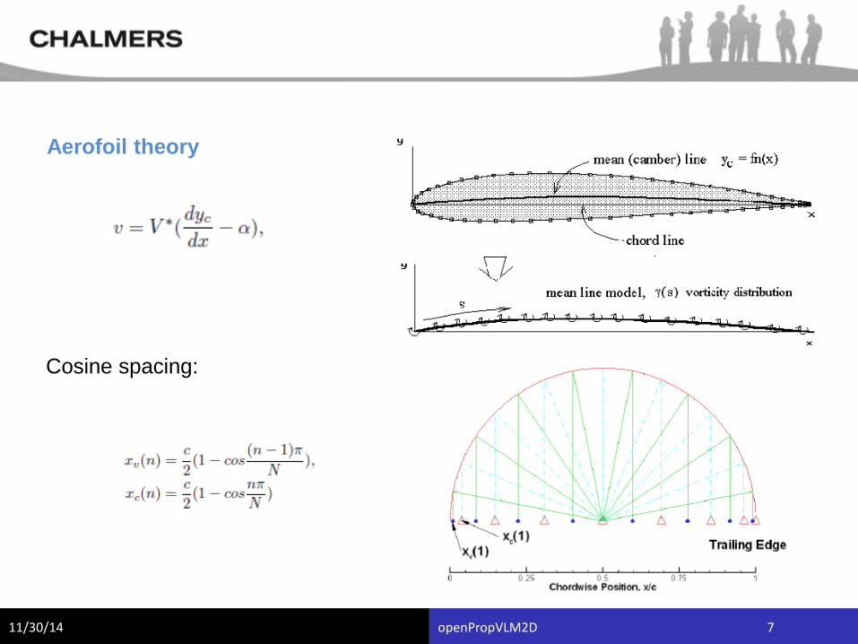
Aerofoil theory
Cosine spacing:
11/30/14 openPropVLM2D 8
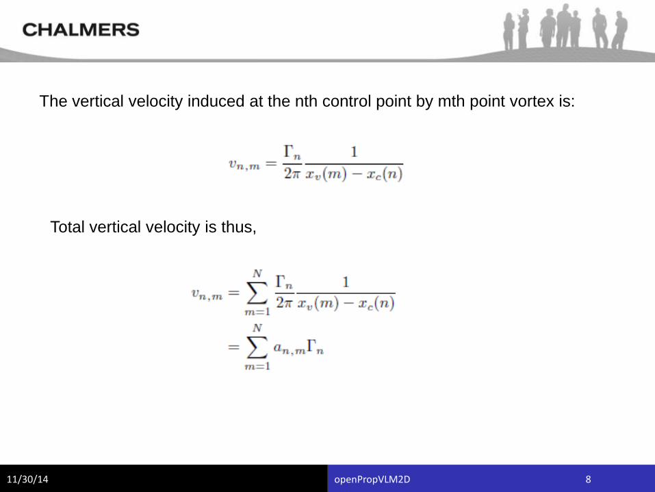
The vertical velocity induced at the nth control point by mth point vortex is:
Total vertical velocity is thus,
11/30/14 openPropVLM2D 9
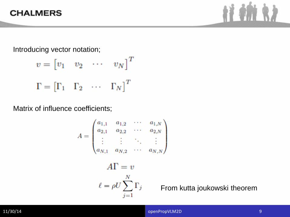
Introducing vector notation;
Matrix of influence coefficients;
From kutta joukowski theorem
11/30/14 openPropVLM2D 10
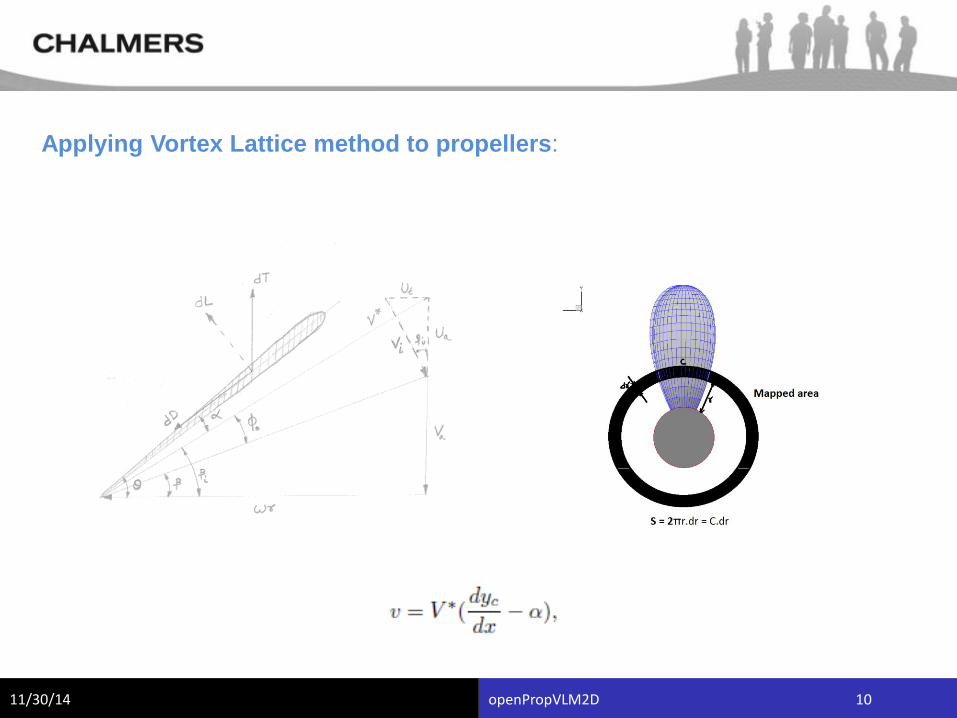
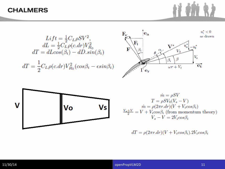
Applying Vortex Lattice method to propellers:
11/30/14 openPropVLM2D 11
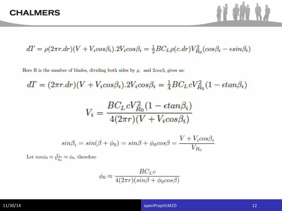
11/30/14 openPropVLM2D 12
11/30/14 openPropVLM2D 13
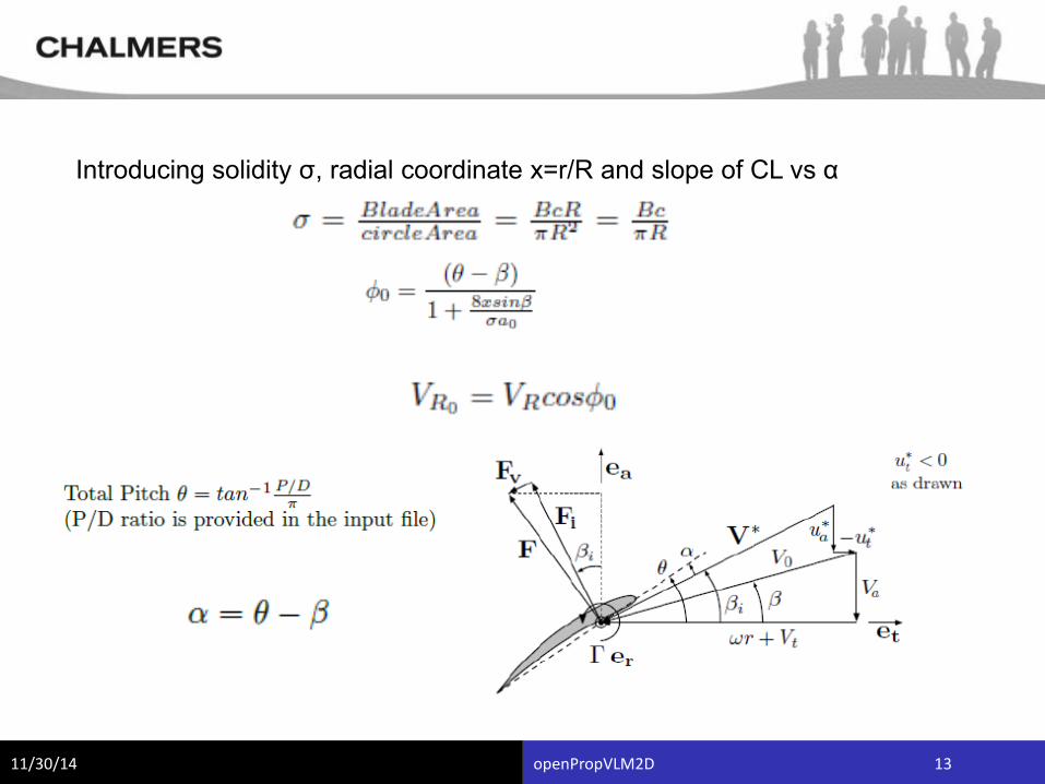
Introducing solidity σ, radial coordinate x=r/R and slope of CL vs α
11/30/14 openPropVLM2D 14
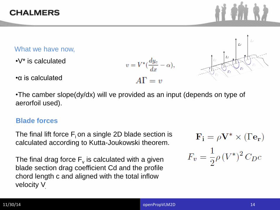
What we have now,
•V* is calculated
•α is calculated
•The camber slope(dy/dx) will ve provided as an input (depends on type of
aerorfoil used).
Blade forces
The final lift force Fi on a single 2D blade section is
calculated according to Kutta-Joukowski theorem.
The final drag force Fv is calculated with a given
blade section drag coefficient Cd and the profile
chord length c and aligned with the total inflow
velocity V.
11/30/14 openPropVLM2D 15
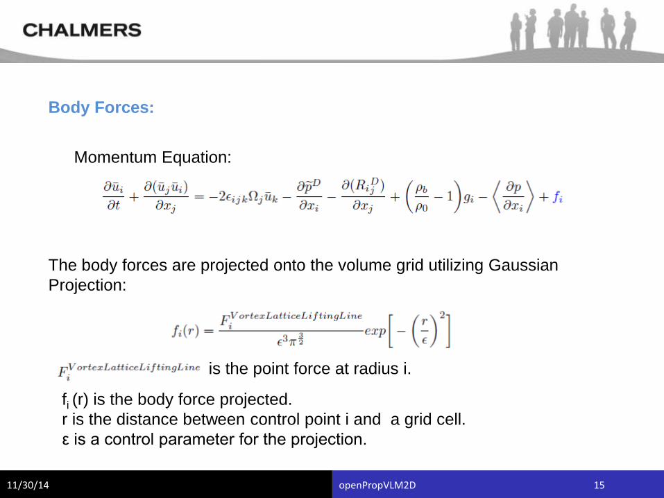
Body Forces:
Momentum Equation:
The body forces are projected onto the volume grid utilizing Gaussian
Projection:
is the point force at radius i.
fi (r) is the body force projected.
r is the distance between control point i and a grid cell.
ε is a control parameter for the projection.
11/30/14 openPropVLM2D 16
Features:
•Model the propeller forces in a transient simulations, accounting for
•changes in inflow.
•Non uniform thrust generation.
•Introduce forces back to the volume grid.
•Run in parallel disregarding the propeller position.
•Create several propellers within one domain.
•Effect of Blade twist.
•Account for the cross sectional properties (aerofoil, camber, chord etc.)
•Shape of Blade ( accounts for scewness).
•Circulation distribution need not be specified.
•Pitch can be varied.
•Works also for off design conditions (contra rotating).
11/30/14 openPropVLM2D 17
Limitations
•+x must be east, +y must be north and +z must be up.
•The propeller geometry has to be specified.
•There is no hub-effect taken into account.
•Accounting for cross flow parameters.
•The interpolation for the outermost vertex radii needs to be improved.
•Only for convention propellers.
•No output plots regarding performance such a efficiency , Thrust etc.
11/30/14 openPropVLM2D 18
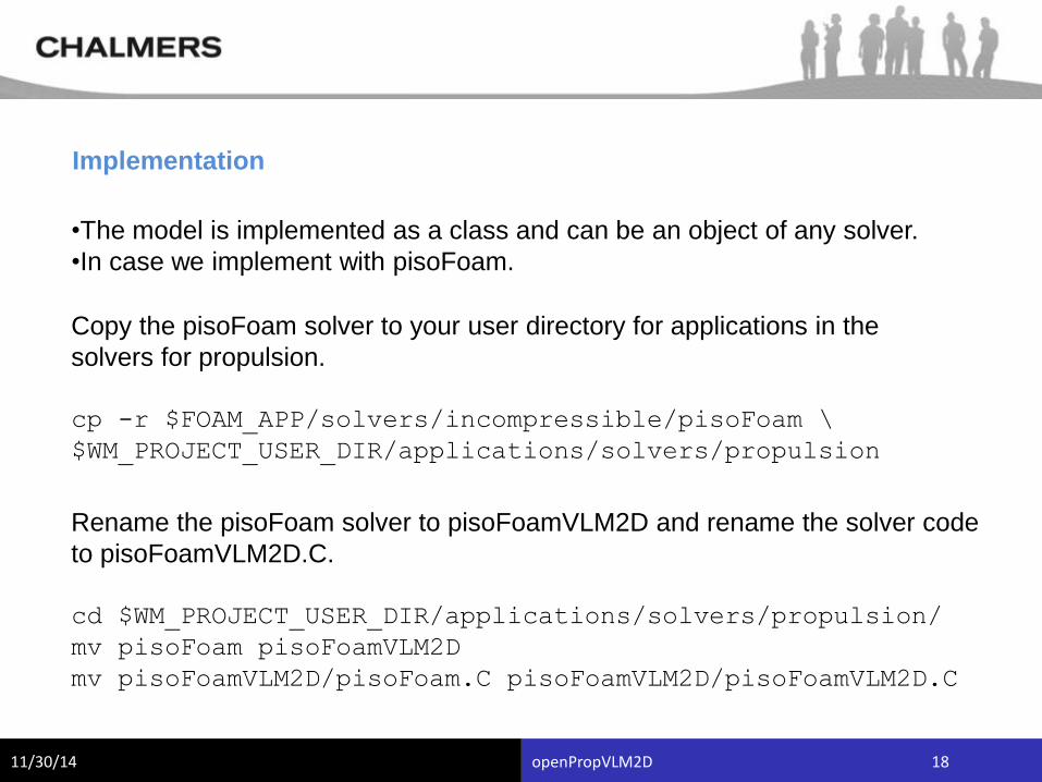
Implementation
•The model is implemented as a class and can be an object of any solver.
•In case we implement with pisoFoam.
Copy the pisoFoam solver to your user directory for applications in the
solvers for propulsion.
cp -r $FOAM_APP/solvers/incompressible/pisoFoam \
$WM_PROJECT_USER_DIR/applications/solvers/propulsion
Rename the pisoFoam solver to pisoFoamVLM2D and rename the solver code
to pisoFoamVLM2D.C.
cd $WM_PROJECT_USER_DIR/applications/solvers/propulsion/
mv pisoFoam pisoFoamVLM2D
mv pisoFoamVLM2D/pisoFoam.C pisoFoamVLM2D/pisoFoamVLM2D.C
11/30/14 openPropVLM2D 19
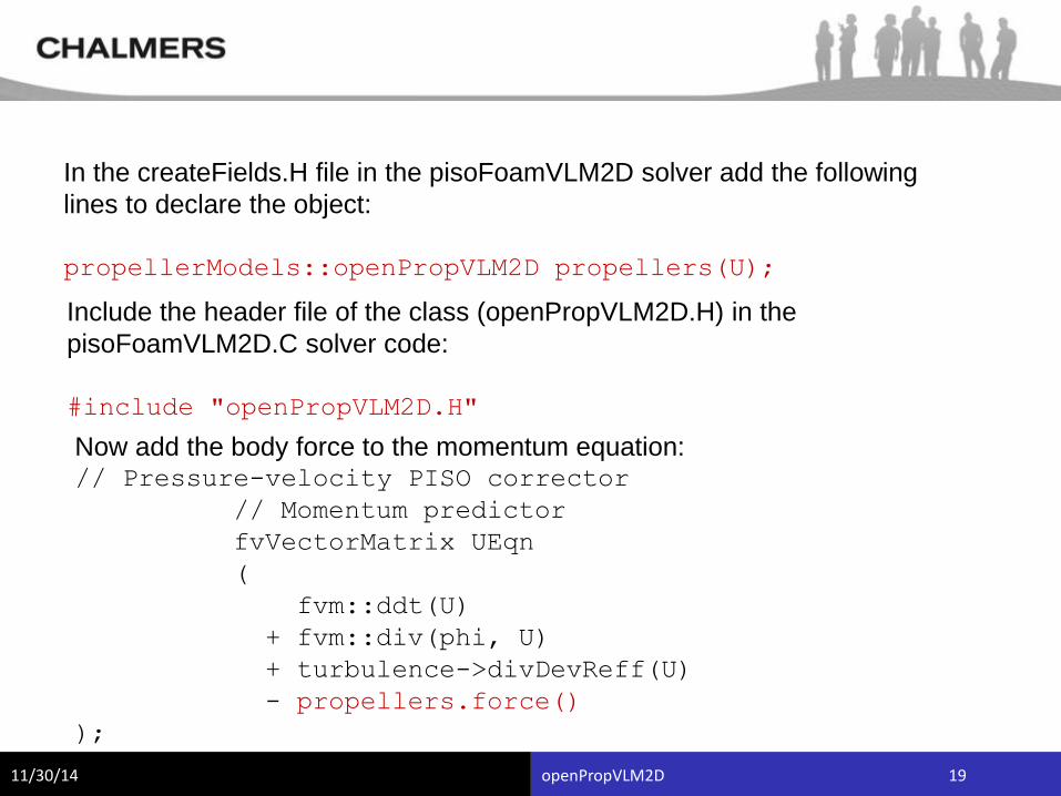
In the createFields.H file in the pisoFoamVLM2D solver add the following
lines to declare the object:
propellerModels::openPropVLM2D propellers(U);
Include the header file of the class (openPropVLM2D.H) in the
pisoFoamVLM2D.C solver code:
#include "openPropVLM2D.H"
Now add the body force to the momentum equation:// Pressure-velocity PISO corrector
// Momentum predictor
fvVectorMatrix UEqn
(
fvm::ddt(U)
+ fvm::div(phi, U)
+ turbulence->divDevReff(U)
- propellers.force()
);
11/30/14 openPropVLM2D 20
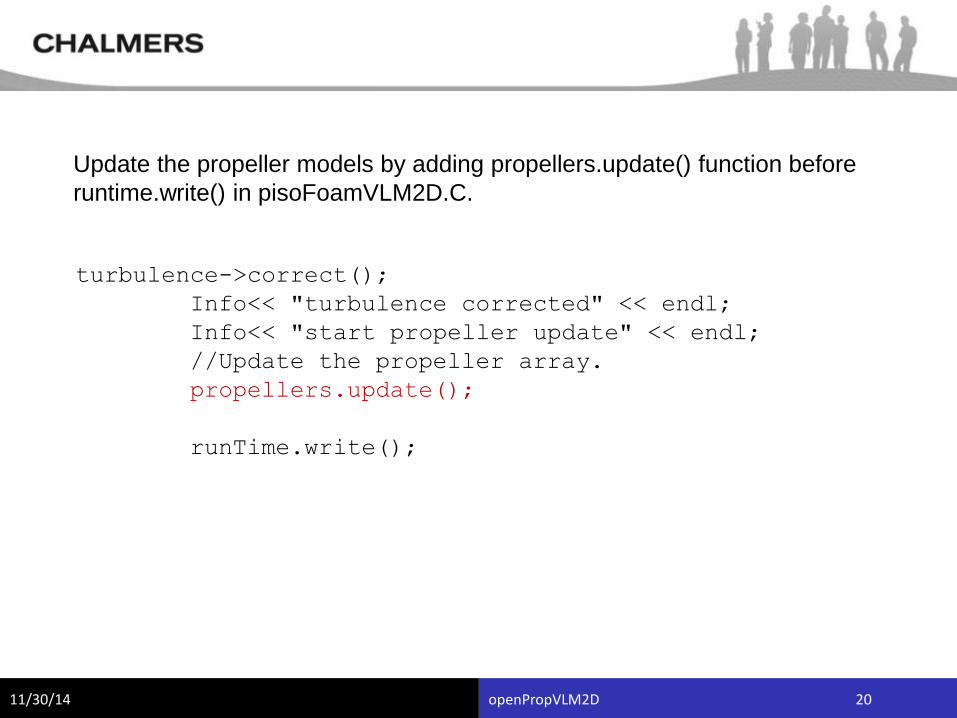
Update the propeller models by adding propellers.update() function before
runtime.write() in pisoFoamVLM2D.C.
turbulence->correct();
Info<< "turbulence corrected" << endl;
Info<< "start propeller update" << endl;
//Update the propeller array.
propellers.update();
runTime.write();
11/30/14 openPropVLM2D 21
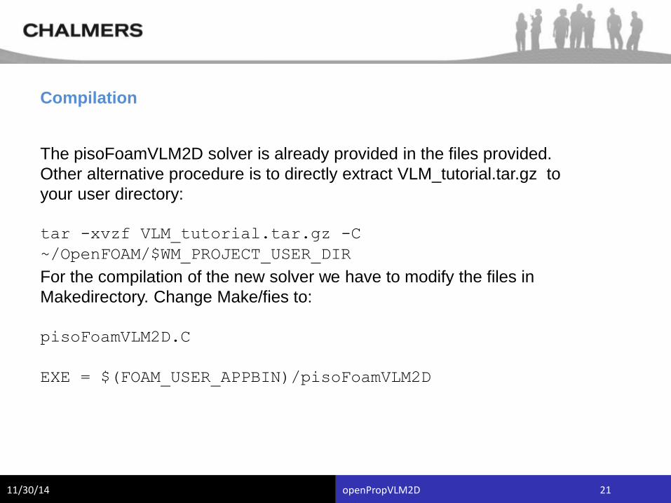
The pisoFoamVLM2D solver is already provided in the files provided.
Other alternative procedure is to directly extract VLM_tutorial.tar.gz to
your user directory:
tar -xvzf VLM_tutorial.tar.gz -C
~/OpenFOAM/$WM_PROJECT_USER_DIR
Compilation
For the compilation of the new solver we have to modify the files in
Makedirectory. Change Make/fies to:
pisoFoamVLM2D.C
EXE = $(FOAM_USER_APPBIN)/pisoFoamVLM2D
11/30/14 openPropVLM2D 22
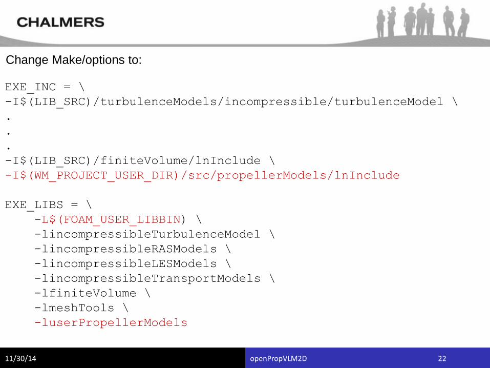
Change Make/options to:
EXE_INC = \
-I$(LIB_SRC)/turbulenceModels/incompressible/turbulenceModel \
.
.
.
-I$(LIB_SRC)/finiteVolume/lnInclude \
-I$(WM_PROJECT_USER_DIR)/src/propellerModels/lnInclude
EXE_LIBS = \
-L$(FOAM_USER_LIBBIN) \
-lincompressibleTurbulenceModel \
-lincompressibleRASModels \
-lincompressibleLESModels \
-lincompressibleTransportModels \
-lfiniteVolume \
-lmeshTools \
-luserPropellerModels
11/30/14 openPropVLM2D 23
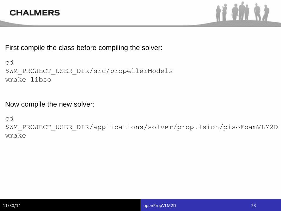
First compile the class before compiling the solver:
cd
$WM_PROJECT_USER_DIR/src/propellerModels
wmake libso
Now compile the new solver:
cd
$WM_PROJECT_USER_DIR/applications/solver/propulsion/pisoFoamVLM2D
wmake
11/30/14 openPropVLM2D 24
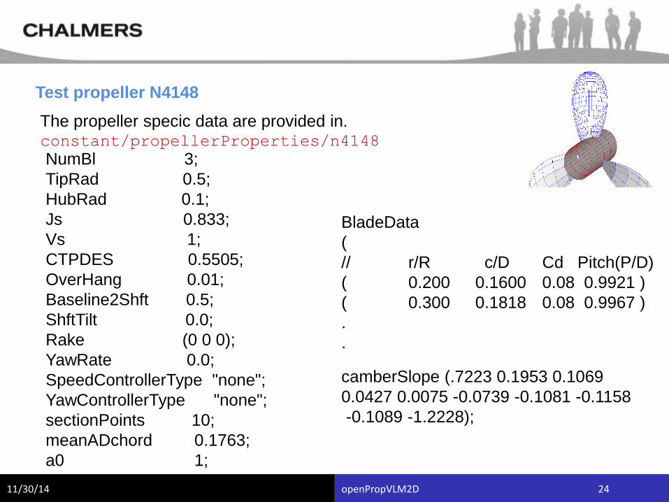
Test propeller N4148
The propeller specic data are provided in.constant/propellerProperties/n4148
NumBl 3;
TipRad 0.5;
HubRad 0.1;
Js 0.833;
Vs 1;
CTPDES 0.5505;
OverHang 0.01;
Baseline2Shft 0.5;
ShftTilt 0.0;
Rake (0 0 0);
YawRate 0.0;
SpeedControllerType "none";
YawControllerType "none";
sectionPoints 10;
meanADchord 0.1763;
a0 1;
BladeData
(
// r/R c/D Cd Pitch(P/D)
( 0.200 0.1600 0.08 0.9921 )
( 0.300 0.1818 0.08 0.9967 )
.
.
camberSlope (.7223 0.1953 0.1069
0.0427 0.0075 -0.0739 -0.1081 -0.1158
-0.1089 -1.2228);
11/30/14 openPropVLM2D 25
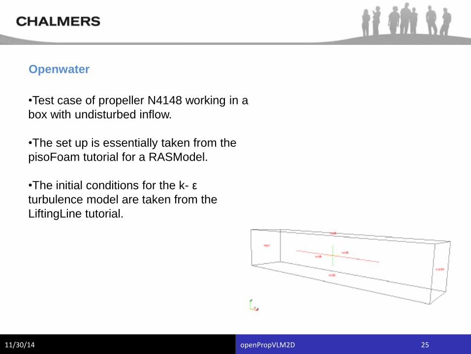
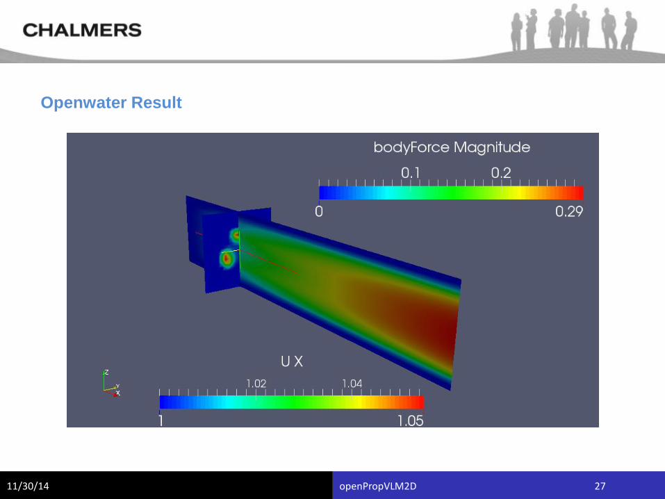
Openwater
•Test case of propeller N4148 working in a
box with undisturbed inflow.
•The set up is essentially taken from the
pisoFoam tutorial for a RASModel.
•The initial conditions for the k- ε
turbulence model are taken from the
LiftingLine tutorial.
11/30/14 openPropVLM2D 26
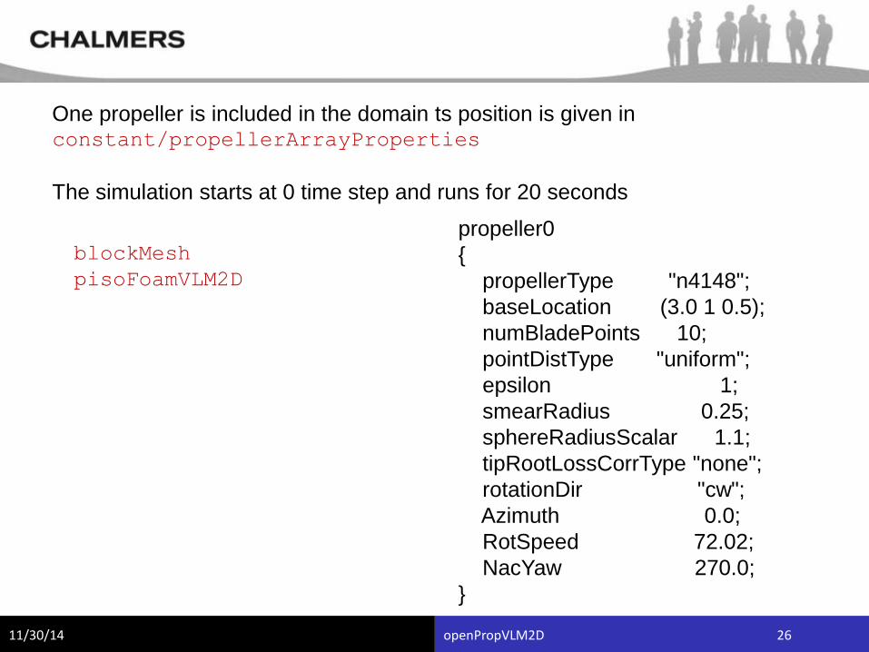
One propeller is included in the domain ts position is given inconstant/propellerArrayProperties
The simulation starts at 0 time step and runs for 20 seconds
blockMesh
pisoFoamVLM2D
propeller0
{
propellerType "n4148";
baseLocation (3.0 1 0.5);
numBladePoints 10;
pointDistType "uniform";
epsilon 1;
smearRadius 0.25;
sphereRadiusScalar 1.1;
tipRootLossCorrType "none";
rotationDir "cw";
Azimuth 0.0;
RotSpeed 72.02;
NacYaw 270.0;
}
11/30/14 openPropVLM2D 27
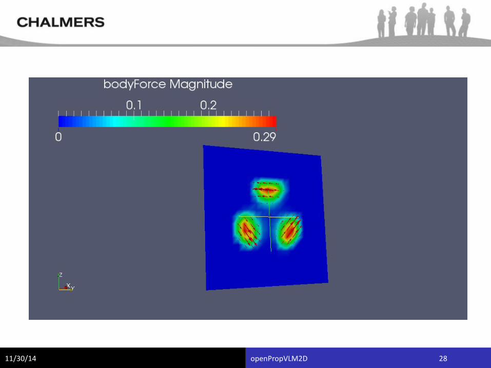
Openwater Result
11/30/14 openPropVLM2D 28
11/30/14 openPropVLM2D 29
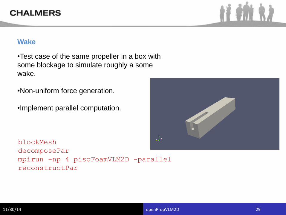
Wake
•Test case of the same propeller in a box with
some blockage to simulate roughly a some
wake.
•Non-uniform force generation.
•Implement parallel computation.
blockMesh
decomposePar
mpirun -np 4 pisoFoamVLM2D -parallel
reconstructPar
11/30/14 openPropVLM2D 30
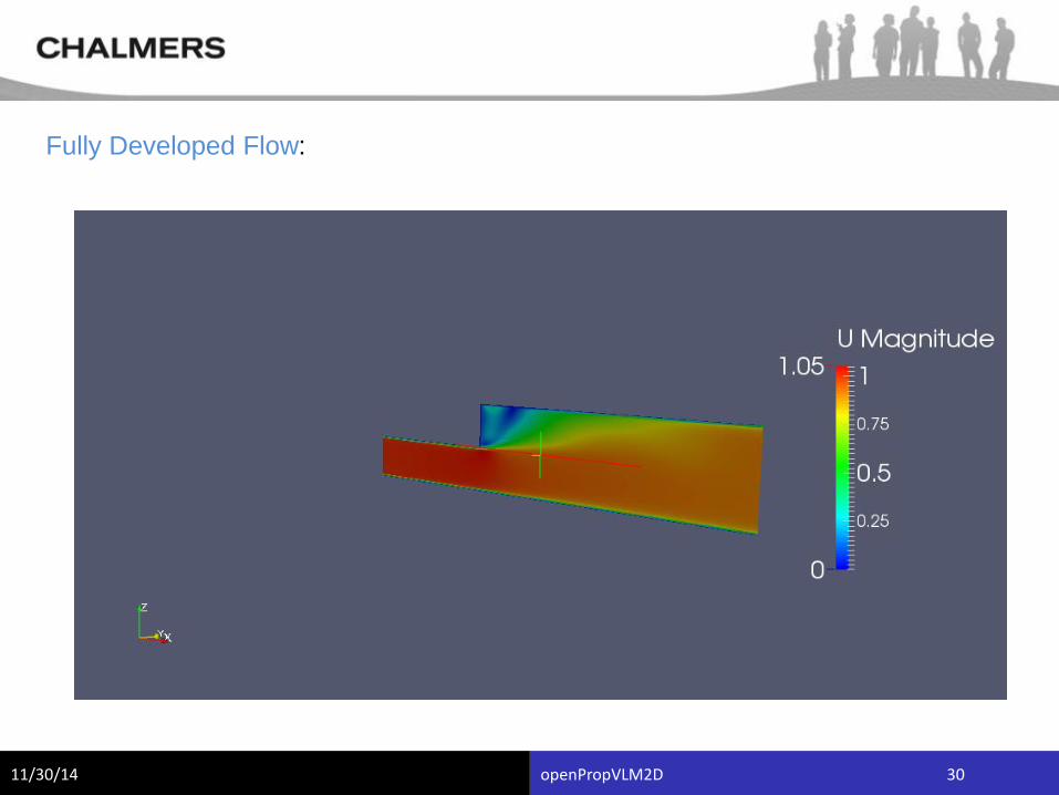
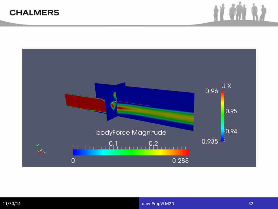
Fully Developed Flow:
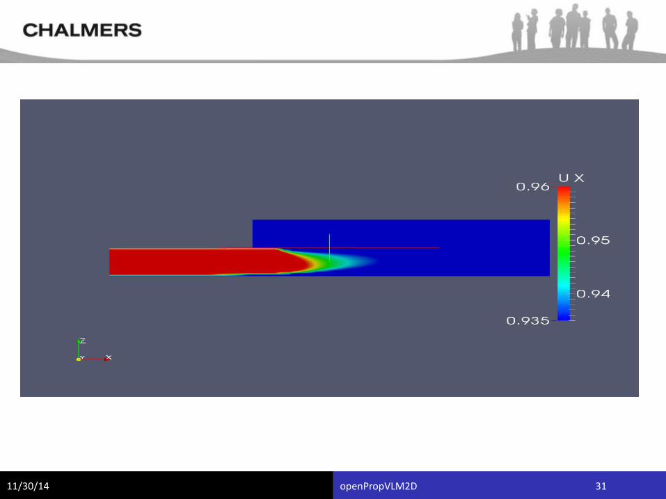
11/30/14 openPropVLM2D 31
11/30/14 openPropVLM2D 32
11/30/14 openPropVLM2D 33
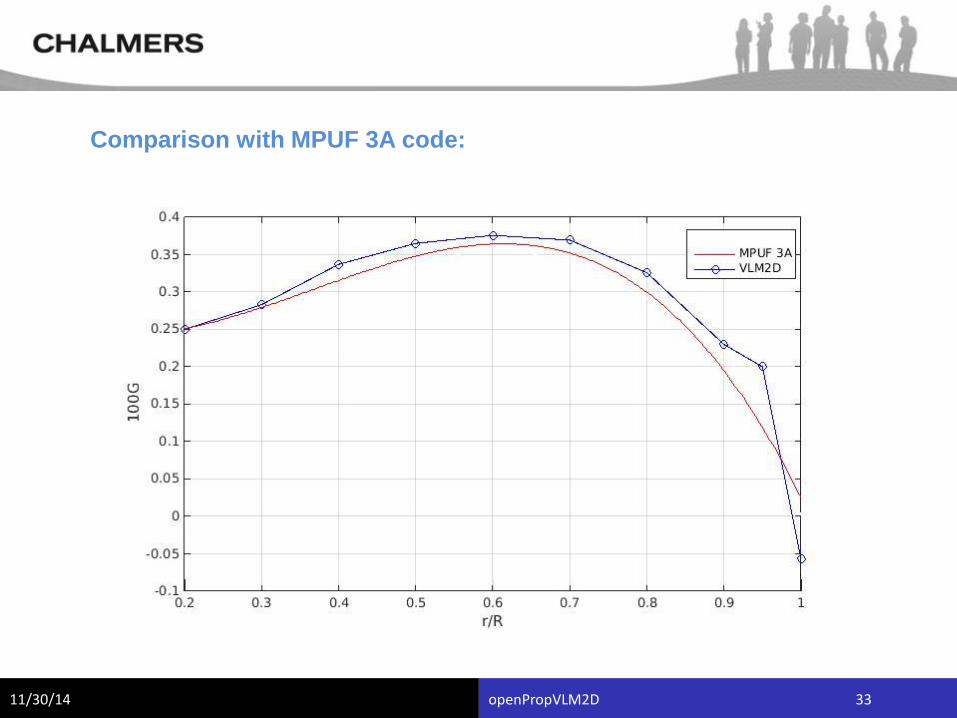
Comparison with MPUF 3A code:
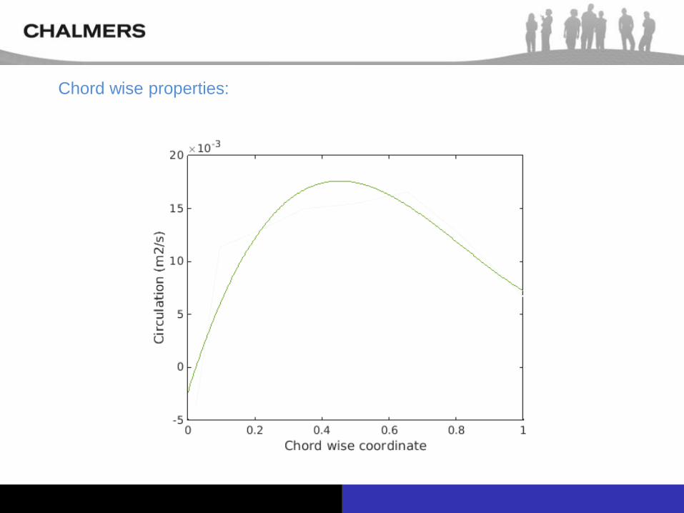
Chord wise properties:
11/30/14 openPropVLM2D 35
Future Work
•Creating an 3D model and testing with variable cross
section.
•Introduce the effect due to Hub.
•Improvising the mesh and capture the tip vortices.
•Applying to non- conventional propellers.
•Introduce model to real ship wake.