Embed Size (px)
Citation preview
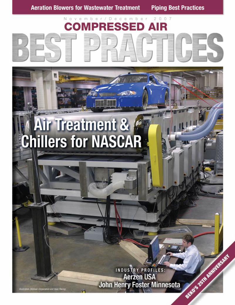
N o v e m b e r / D e c e m b e r 2 0 0 7
Aeration Blowers for Wastewater Treatment Piping Best Practices
Illustration: Motivair Corporation and Haas Racing
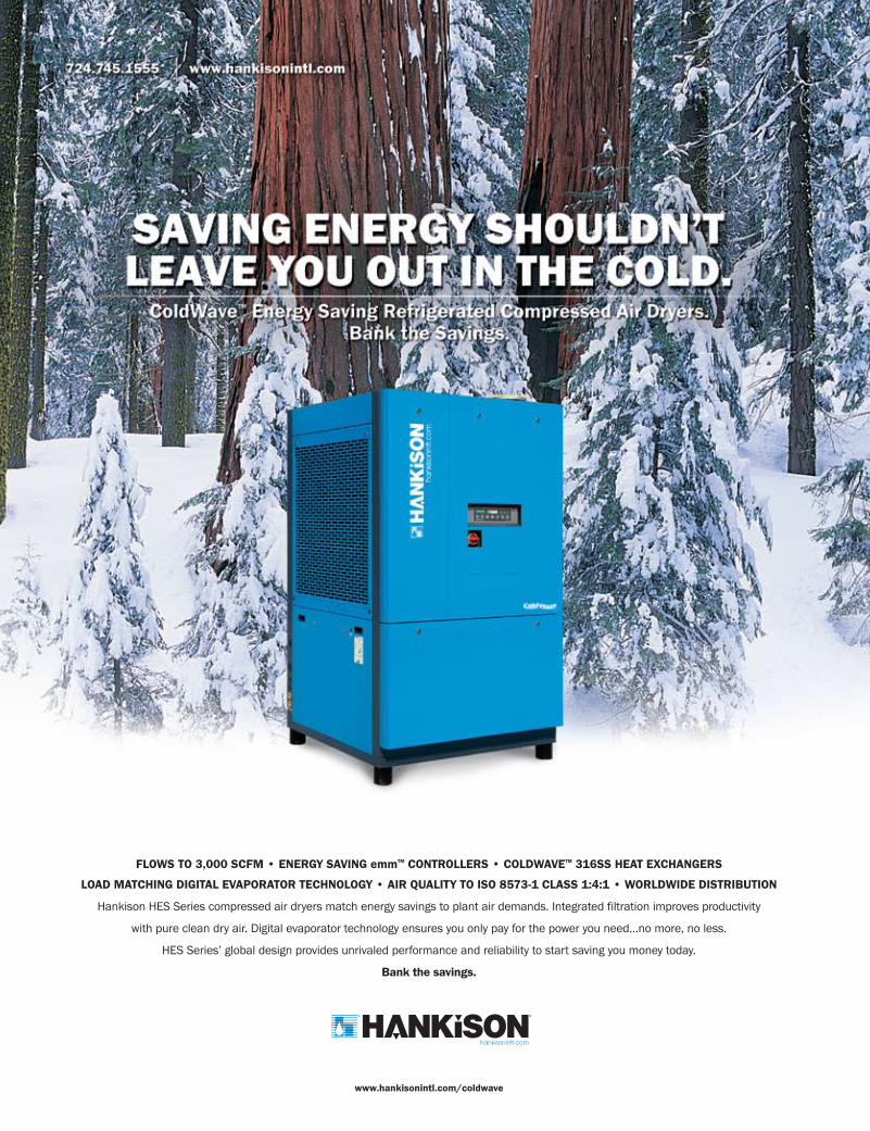
FLOWS TO 3,000 SCFM • ENERGY SAVING emmTM CONTROLLERS • COLDWAVETM 316SS HEAT EXCHANGERS
LOAD MATCHING DIGITAL EVAPORATOR TECHNOLOGY • AIR QUALITY TO ISO 8573-1 CLASS 1:4:1 • WORLDWIDE DISTRIBUTION
Hankison HES Series compressed air dryers match energy savings to plant air demands. Integrated filtration improves productivity
with pure clean dry air. Digital evaporator technology ensures you only pay for the power you need…no more, no less.
HES Series’ global design provides unrivaled performance and reliability to start saving you money today.
Bank the savings.
®®
www.hankisonintl.com/coldwave
0611_1049_SPX_Ad_CABP:CABP_HPETad 5/9/2007 9:29 AM Page 1

Focus Industry | WATer & WAsTeWATer mAnAgemenT | 1 1 – 1 2 / 0 7
4 www.ai rbestpract ices .com
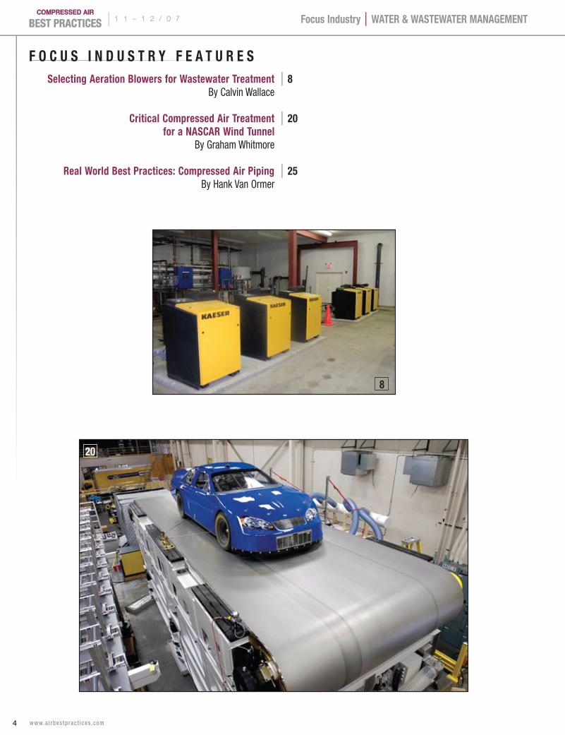
F O C U s I n D U s T r Y F e A T U r e s selecting Aeration Blowers for Wastewater Treatment | 8 By Calvin Wallace
Critical Compressed Air Treatment | 20 for a nAsCAr Wind Tunnel By Graham Whitmore
real World Best Practices: Compressed Air Piping | 25 By Hank Van Ormer
20
8

www.atlascopco.com
Conserve Energy and Save Money withVariable Speed Drive Compressors
When a major California winemaker expanded its grapesqueezing operation, the ability to automatically control thevariable demand of compressed air provided energy savingsthat helped the project pay for itself faster. Atlas CopcoVariable Speed Drive (VSD) air compressors precisely matchthe output of compressed air to your air system's fluctuatingdemand.
Atlas Copco has an established record of success creating solutions for our customers whose demand for compressed air varies. Our VSD compressors offer themost advanced technology and the greatest energy efficiencyon the market today.
More than 90% of all compressor applications are high poten-tial candidates for VSD compressors, and we work with ourcustomers and their engineers to design and implement energyefficient solutions for upgrades and new construction.
If you want to pay only for the compressed air youneed, please contact Atlas Copco at...
1-800-232-3234 or email us at: [email protected]
AC VSD Ad 12/1/06 1:04 PM Page 1
| 1 1 – 1 2 / 0 7
6 www.ai rbestpract ices .com
Compressed Air Industry | WATer & WAsTeWATer mAnAgemenT
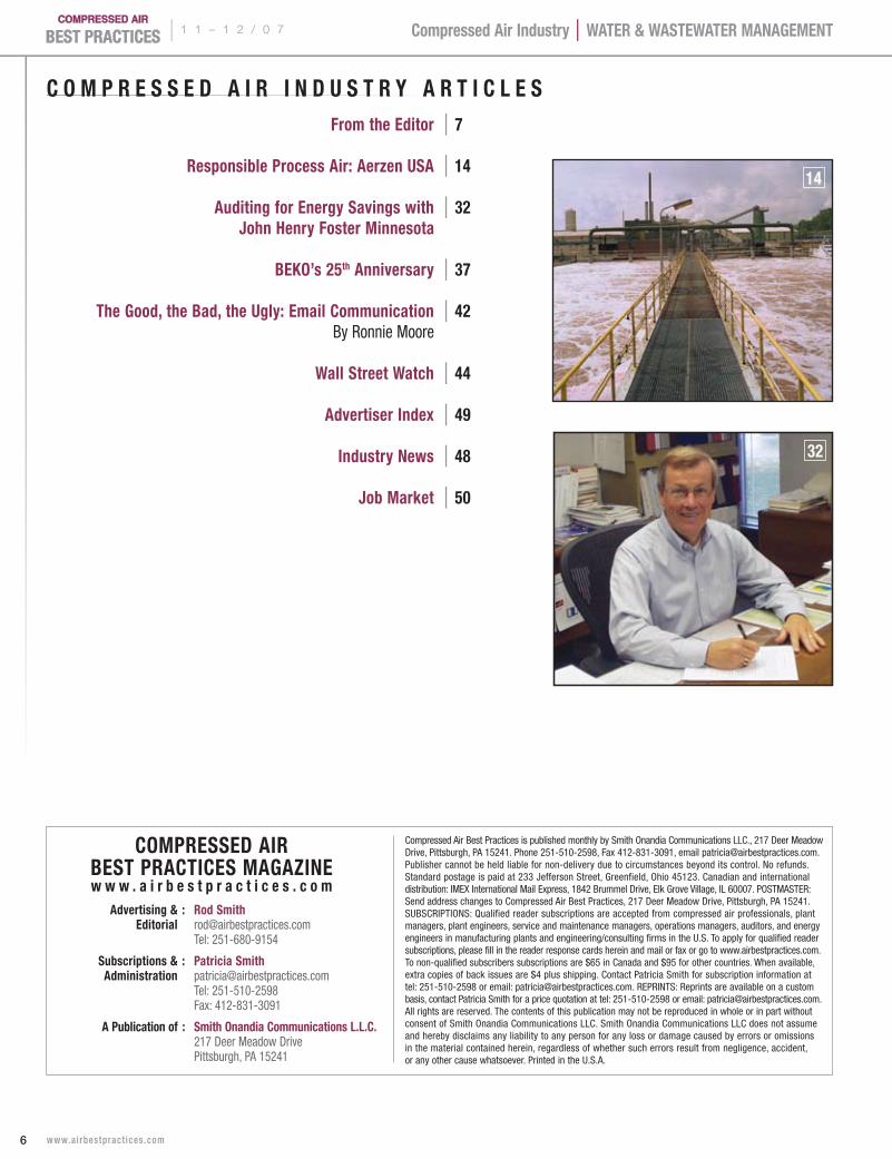
C O m P r e s s e D A I r I n D U s T r Y A r T I C l e s From the editor | 7
responsible Process Air: Aerzen UsA | 14
Auditing for energy savings with | 32 John Henry Foster minnesota
BeKO’s 25th Anniversary | 37
The good, the Bad, the Ugly: email Communication | 42 By Ronnie Moore
Wall street Watch | 44
Advertiser Index | 49
Industry news | 48 Job market | 50
Compressed Air Best Practices is published monthly by Smith Onandia Communications LLC., 217 Deer Meadow Drive, Pittsburgh, PA 15241. Phone 251-510-2598, Fax 412-831-3091, email [email protected]. Publisher cannot be held liable for non-delivery due to circumstances beyond its control. No refunds. Standard postage is paid at 233 Jefferson Street, Greenfield, Ohio 45123. Canadian and international distribution: IMEX International Mail Express, 1842 Brummel Drive, Elk Grove Village, IL 60007. POSTMASTER: Send address changes to Compressed Air Best Practices, 217 Deer Meadow Drive, Pittsburgh, PA 15241. SUBSCRIPTIONS: Qualified reader subscriptions are accepted from compressed air professionals, plant managers, plant engineers, service and maintenance managers, operations managers, auditors, and energy engineers in manufacturing plants and engineering/consulting firms in the U.S. To apply for qualified reader subscriptions, please fill in the reader response cards herein and mail or fax or go to www.airbestpractices.com. To non-qualified subscribers subscriptions are $65 in Canada and $95 for other countries. When available, extra copies of back issues are $4 plus shipping. Contact Patricia Smith for subscription information at tel: 251-510-2598 or email: [email protected]. REPRINTS: Reprints are available on a custom basis, contact Patricia Smith for a price quotation at tel: 251-510-2598 or email: [email protected]. All rights are reserved. The contents of this publication may not be reproduced in whole or in part without consent of Smith Onandia Communications LLC. Smith Onandia Communications LLC does not assume and hereby disclaims any liability to any person for any loss or damage caused by errors or omissions in the material contained herein, regardless of whether such errors result from negligence, accident, or any other cause whatsoever. Printed in the U.S.A.
COmPresseD AIr BesT PrACTICes mAgAzInew w w . a i r b e s t p r a c t i c e s . c o m
Advertising & : rod smith editorial [email protected] Tel: 251-680-9154
subscriptions & : Patricia smith Administration [email protected] Tel: 251-510-2598 Fax: 412-831-3091
A Publication of : smith Onandia Communications l.l.C. 217 Deer Meadow Drive Pittsburgh, PA 15241
14
32
1 1 – 1 2 / 0 7 |
7 www.ai rbestpract ices .com
Compressed Air Industry | WATer & WAsTeWATer mAnAgemenT
F r O m T H e e D I T O rThe Diversity of Compressed Air
The ingenuity of engineers and their applications for
compressed air never cease to amaze me. We were so
impressed by the new Wind Shear Project at Haas Racing
that we had to put it on this month’s cover. Located in
Concorde, North Carolina, this unique test facility will
be the first to measure NASCAR race car performance
at speeds up to 180 mph! Motivair Corporation was
kind enough to share with us how they designed
the air treatment and chillers, which ensure the quality of the instrument
air used for the pneumatic suspension and tire-test measurement equipment.
Wastewater treatment is slightly less glamorous than NASCAR. The article
“Selecting Aeration Blowers” provides interesting selection criteria and some
case studies of how small wastewater plants are making it possible for more
“eco-friendly” residential developments. The spirit of responsibility to customers,
employees and the environment is one that Aerzen USA also talks about
in their article “Responsible Process Air.”
Compressed air audits never cease to amaze with their “Win/Win” characteristics
for end users. John Henry Foster Minnesota has been a pioneer in this area
and they share with us some of their techniques and philosophies in this edition.
JHF Minnesota is progressive in their commitment to audit not only compressed
air, but also the vacuum, blowers, pneumatics and chillers in a facility.
This all-in-one auditing process provides even greater value to their customers.
During this time of year, businesses start planning for the next year and
Compressed Air Best Practices Magazine is no different. Thanks to the support
of end users, utility companies and the compressed air industry, we look
forward to 2008 with high hopes. We have plans to increase circulation,
editorial content and to offer readers digital versions of the magazine.
Thank you for your continued support.
rOD smITH
Focus Industry | WATer & WAsTeWATer mAnAgemenT | 1 1 – 1 2 / 0 7
8 www.ai rbestpract ices .com
seleCTIng AerATIOn BlOWers
Infrastructure spending in the United States has not kept
pace with the population growth and many wastewater
treatment plants are at peak capacity. The nation’s waste-
water systems and their ratepayers face a major challenge
in funding the expansion, replacement and maintenance
of aging infrastructure over the next several decades. For
this reason, plant engineers and operators have significantly
increased the focus on lifecycle costs including initial price,
installation, maintenance and energy costs. Additionally, new
regulations require the reducing nutrients in the effluent
discharged from existing plants.
One method to meet these challenges is simply to increase
the size of the wastewater treatment plant. Another way
is integrating processes such as supplemental biological
contactors by incorporating subsurface aeration equipment
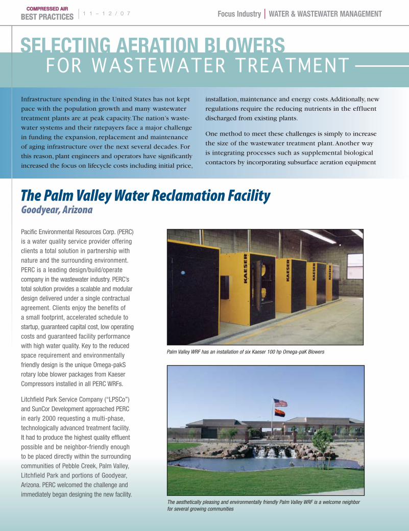
Pacific Environmental Resources Corp. (PERC) is a water quality service provider offering clients a total solution in partnership with nature and the surrounding environment. PERC is a leading design/build/operate company in the wastewater industry. PERC’s total solution provides a scalable and modular design delivered under a single contractual agreement. Clients enjoy the benefits of a small footprint, accelerated schedule to startup, guaranteed capital cost, low operating costs and guaranteed facility performance with high water quality. Key to the reduced space requirement and environmentally friendly design is the unique Omega-pakS rotary lobe blower packages from Kaeser Compressors installed in all PERC WRFs.
Litchfield Park Service Company (“LPSCo”) and SunCor Development approached PERC in early 2000 requesting a multi-phase, technologically advanced treatment facility. It had to produce the highest quality effluent possible and be neighbor-friendly enough to be placed directly within the surrounding communities of Pebble Creek, Palm Valley, Litchfield Park and portions of Goodyear, Arizona. PERC welcomed the challenge and immediately began designing the new facility.
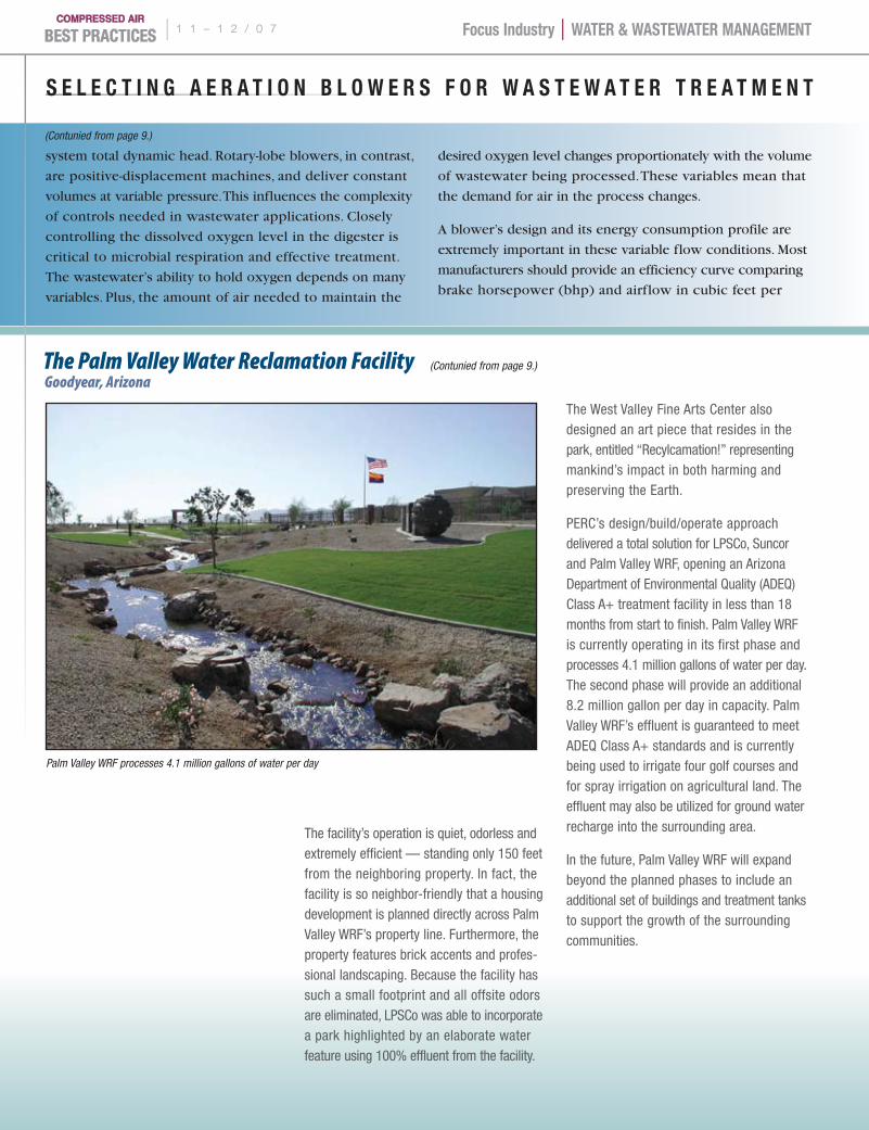
Palm Valley WRF has an installation of six Kaeser 100 hp Omega-paK Blowers
The aesthetically pleasing and environmentally friendly Palm Valley WRF is a welcome neighbor for several growing communities
for WasteWater treatment
The Palm Valley Water Reclamation FacilityGoodyear, Arizona
Focus Industry | WATer & WAsTeWATer mAnAgemenT 1 1 – 1 2 / 0 7 |
9 www.ai rbestpract ices .com
BY CAlvIn WAllACe
into existing plant operations. This second means presents
the added benefit of increasing plant capacity without
requiring plant expansion.
Common to both methods, is the need for an increased
oxygen supply to support the process. Blowers have become
the most common and most efficient method to introduce
oxygen to aerobic digesters. Blowers can replace expensive
liquid oxygen injection systems and inefficient mechanical
surface splashers. Among blowers, there are two common
options: centrifugal blowers and positive displacement
rotary-lobe blowers.
Centrifugal blowers are dynamic machines designed to
produce variable flows at a constant pressure. In other
words, the volume delivery of the blower depends on the
Palm Valley WRF features the PERC Activated Sludge Process™ (ASP) technology utilizing sequential batch reactors incorporated with an advanced biological nutrient removal pro-cess, an Auto Thermophilic Aerobic Digestion (ATAD) process and UV disinfection. The ASP™
technology also includes the highest quality equipment available to ensure optimum effluent quality, dependability and a long life span.
Kaeser Compressors’ Omega-paK FB 620 100 hp rotary lobe blower packages are an integral part of the PERC ASP™ design and are used in both the biological process train and biosolids stabilization. Kaeser’s equipment also provides air to the facility’s jet aeration system, which is crucial to ensure the ASP™ system produces high quality effluent.
There are six FB 620 packages installed in the Palm Valley WRF. Their space-saving design allows ample service access but requires minimal floor space. In fact, the FB 620 Omega-paKs require approximately 40% less space than competitive blower packages. PERC is able to significantly reduce the overall size of their facilities due to this important feature. These energy-efficient packages offer reduced pulsations to protect piping and extend the service life of downstream aeration and diffuser equipment.
The Omega-paK units also feature sound-dampening enclosures that reduce noise levels to approximately 76 dB(A) — low enough to hold a conversation right next to an operational unit. Since blowers are generally the largest noise producer in this type of facility, the Omega-paK’s incredibly
low noise levels make PERC’s offering even more attractive. Palm Valley was the first PERC facility to utilize these blower packages, and because they exceeded all quality and performance expectations, Kaeser blower packages are now incorporated into every WRF that PERC designs and builds.
GERMAN ENGINEERING
©2007 Curtis-Toledo, Inc.WWW.DISCOVERCURTIS.COM
D I S C O V E R
17637 07 CTGNL German Ad.indd 1 9/4/07 4:15:30 PM
(Contunied on page 10.)
(Contunied on page 10.)
Focus Industry | WATer & WAsTeWATer mAnAgemenT | 1 1 – 1 2 / 0 7
10 www.ai rbestpract ices .com
s e l e C T I n g A e r A T I O n B l O W e r s F O r W A s T e W A T e r T r e A T m e n T
system total dynamic head. Rotary-lobe blowers, in contrast,
are positive-displacement machines, and deliver constant
volumes at variable pressure. This influences the complexity
of controls needed in wastewater applications. Closely
controlling the dissolved oxygen level in the digester is
critical to microbial respiration and effective treatment.
The wastewater’s ability to hold oxygen depends on many
variables. Plus, the amount of air needed to maintain the
desired oxygen level changes proportionately with the volume
of wastewater being processed. These variables mean that
the demand for air in the process changes.
A blower’s design and its energy consumption profile are
extremely important in these variable flow conditions. Most
manufacturers should provide an efficiency curve comparing
brake horsepower (bhp) and airflow in cubic feet per
The facility’s operation is quiet, odorless and extremely efficient — standing only 150 feet from the neighboring property. In fact, the facility is so neighbor-friendly that a housing development is planned directly across Palm Valley WRF’s property line. Furthermore, the property features brick accents and profes-sional landscaping. Because the facility has such a small footprint and all offsite odors are eliminated, LPSCo was able to incorporate a park highlighted by an elaborate water feature using 100% effluent from the facility.
The West Valley Fine Arts Center also designed an art piece that resides in the park, entitled “Recylcamation!” representing mankind’s impact in both harming and preserving the Earth.
PERC’s design/build/operate approach delivered a total solution for LPSCo, Suncor and Palm Valley WRF, opening an Arizona Department of Environmental Quality (ADEQ) Class A+ treatment facility in less than 18 months from start to finish. Palm Valley WRF is currently operating in its first phase and processes 4.1 million gallons of water per day. The second phase will provide an additional 8.2 million gallon per day in capacity. Palm Valley WRF’s effluent is guaranteed to meet ADEQ Class A+ standards and is currently being used to irrigate four golf courses and for spray irrigation on agricultural land. The effluent may also be utilized for ground water recharge into the surrounding area.
In the future, Palm Valley WRF will expand beyond the planned phases to include an additional set of buildings and treatment tanks to support the growth of the surrounding communities.
Palm Valley WRF processes 4.1 million gallons of water per day
The Palm Valley Water Reclamation FacilityGoodyear, Arizona
(Contunied from page 9.)
(Contunied from page 9.)
Focus Industry | WATer & WAsTeWATer mAnAgemenT 1 1 – 1 2 / 0 7 |
11 www.ai rbestpract ices .com
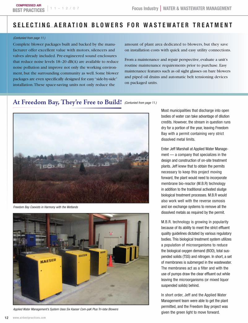
In Portsmouth, Rhode Island, developers are moving full speed ahead at Freedom Bay — a residential development of luxury townhouses serving the burgeoning population of over 55. It is one of many such communities springing up across the country. Freedom Bay’s approach to waste water treatment, on the other hand, is not as common.
This planned development sits at the edge of protected wetlands that boast walking and hiking trails as well as nature preserves. The site of a former church and small school, the land previously featured an onsite water treatment plant. The developers who purchased the land almost fifteen years ago retained the permit on the dormant facility, believing it might be needed one day.
Portsmouth does not have public sewers and there was no option to tie into the neigh-boring town’s sewer system. As plans began to take shape for Freedom Bay, the developers decided to reopen the onsite water treatment plant using updated technology. The Rhode Island Department of Environmental Protection (RIDEP) reviewed the initial plans for the new facility. However, the initial engineering firm hired to design and permit the site was unsuccessful due to their lack of experience with plants this size, as well as several other mitigating concerns.
RIDEP maintains very strict requirements for discharging effluent. The Freedom Bay site did not have soils that were well suited for treated effluent disposal due to high water tables and slow PERC rates. There was an option to discharge the treated effluent in a stream that ultimately feeds into Narragansett Bay.
minute (cfm). A quick comparison between blower type and
manufacturer could reveal efficiency differences of up to 20%.
Centrifugal blowers are highly effective for large flows at
moderate to low pressures. Positive-displacement blowers
are variable over a wide speed range and the power require-
ments are almost directly proportional to the changes in
motor speed. This is a significant per unit energy advantage
that can quickly add up to thousands of dollars in power costs.
Blower type also impacts the bill of materials and installation
costs. Positive displacement blowers generally employ
straightforward and economical controls. For example,
a variable capacity control panel for a positive-displacement
blower consists only of the variable frequency drive and
a process follower such as a dissolved oxygen sensor.
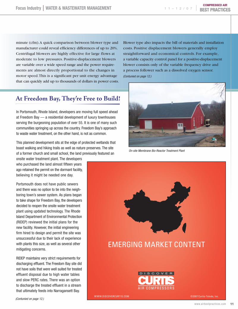
EMERGING MARKET CONTENT
©2007 Curtis-Toledo, Inc.WWW.DISCOVERCURTIS.COM
D I S C O V E R
19282b CTGNL GENRL Emerging.indd1 1 9/4/07 4:18:25 PM
On-site Membrane Bio-Reactor Treatment Plant
At Freedom Bay, They’re Free to Build!
(Contunied on page 12.)
(Contunied on page 12.)
Focus Industry | WATer & WAsTeWATer mAnAgemenT | 1 1 – 1 2 / 0 7
12 www.ai rbestpract ices .com
s e l e C T I n g A e r A T I O n B l O W e r s F O r W A s T e W A T e r T r e A T m e n T
Complete blower packages built and backed by the manu-
facturer offer excellent value with motors, silencers and
valves already included. Pre-engineered sound enclosures
that reduce noise levels 18–20 dB(A) are available to reduce
noise pollution and improve not only the working environ-
ment, but the surrounding community as well. Some blower
packages are even specifically designed for easy “side-by-side”
installation. These space-saving units not only reduce the
amount of plant area dedicated to blowers, but they save
on installation costs with quick and easy utility connections.
From a maintenance and repair perspective, evaluate a unit’s
routine maintenance requirements prior to purchase. Easy
maintenance features such as oil sight glasses on bare blowers
and piped oil drains and automatic belt tensioning devices
on packaged units.
Most municipalities that discharge into open bodies of water can take advantage of dilution credits. However, the stream in question runs dry for a portion of the year, leaving Freedom Bay with a permit containing very strict dissolved metal limits.
Enter Jeff Marshall at Applied Water Manage-ment — a company that specializes in the design and construction of on-site treatment plants. Jeff knew that to obtain the permits necessary to keep this project moving forward, the plant would need to incorporate membrane bio-reactor (M.B.R) technology in addition to the traditional activated sludge biological treatment processes. M.B.R would also work well with the reverse osmosis and ion exchange systems to remove all the dissolved metals as required by the permit.
M.B.R. technology is growing in popularity because of its ability to meet the strict effluent quality guidelines dictated by various regulatory bodies. This biological treatment system utilizes a population of microorganisms to reduce the biological oxygen demand (BOD), total sus-pended solids (TSS) and nitrogen. In short, a set of membranes is submerged in the wastewater. The membranes act as a filter and with the use of pumps draw the clear effluent out while leaving the microorganisms (or mixed liquor suspended solids) behind.
In short order, Jeff and the Applied Water Management team were able to get the plant permitted, and the Freedom Bay project was given the green light to move forward.
Freedom Bay Coexists in Harmony with the Wetlands
Applied Water Management’s System Uses Six Kaeser Com-paK Plus Tri-lobe Blowers
(Contunied from page 11.)
(Contunied from page 11.)
At Freedom Bay, They’re Free to Build!
Focus Industry | WATer & WAsTeWATer mAnAgemenT 1 1 – 1 2 / 0 7 |
13 www.ai rbestpract ices .com
Further, positive displacement blowers are usually field-
repairable, without the need for specialized equipment or
specially trained technicians. Plant maintenance personnel
and standard tools can usually repair them.
As our wastewater treatment infrastructure continues to
age, the costs associated with new plants, plant expansions
and plant modernization will foster ingenuity toward more
effective aeration designs. The growing use of both rotary
lobe and centrifugal blowers for aeration applications
reflects the important cost and performance advantages
they present over traditional methods. Water treatment
plant designers, owners and operators now have even
greater opportunities to optimize aeration systems by
properly selecting blower technology.
For more information contact Calvin Wallace, Kaeser Compressors, tel: 1-800-777-7873, email: [email protected], www.kaeserusa.com
Part of Applied Water Management’s plan was to incorporate Kaeser Omega blower technology. “We have historically used Kaeser Com-paK Plus units,” commented Jeff, “because we recognize their value-added on a project like this one.” Citing Kaeser’s unitized approach, low noise levels, easy maintenance, customer support and reliability, Jeff continued, “Kaeser and Kaeser products have performed well in all the preceding categories.”
Just like in a traditional activated sludge plant, Kaeser’s blowers serve to aerate the bacteria and organisms that are part of the biological process. In addition to providing aeration, these blowers also provide air to scour the membranes. In the simplest of terms, the air bubbles provide a mechanical means of knocking the sludge off the membrane plates.
At Freedom Bay, there are six Kaeser DB 130 Com-paK Plus tri-lobe blower units. Their space-saving design and extremely low- pulsations have allowed them to be installed in a piped parallel arrangement directly in the main building. In fact, the noise level for a Com-paK Plus is only about 75 dB(A). Residents and visitors strolling down the walking trail and past the barn-like water treatment facility would be surprised to know what’s really going on behind the quaint, quiet exterior — the daily processing of 67,000 gallons of wastewater.
The effluent produced at Freedom Bay using Applied Water Management’s complete system is actually cleaner than the water coming out of most household taps. With Phase I well underway, one more phase is planned to fill a lack of retirement housing in the area. By all accounts, this project is a success. But
it is also a clear example of advancing tech-nologies allowing business to meet the needs of a growing community, while also respecting the natural beauty and enhancing the enjoy-ment of natural wetlands. Clean, quiet and efficient wastewater treatment — a freedom every community should enjoy.
AMERICAN INGENUITY
©2007 Curtis-Toledo, Inc.WWW.DISCOVERCURTIS.COM
D I S C O V E R
19282c CTGNL GENRL American.ind1 1 9/4/07 4:20:20 PM
| 1 1 – 1 2 / 0 7
14 www.ai rbestpract ices .com
Compressed Air Industry | WATer & WAsTeWATer mAnAgemenT
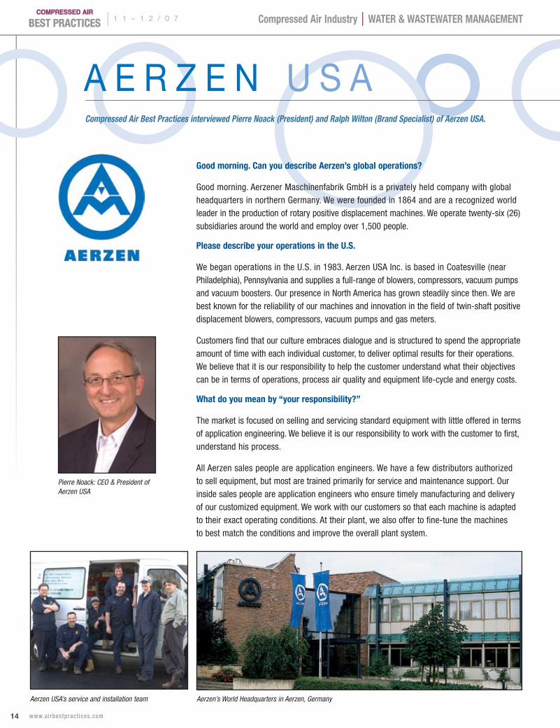
Compressed Air Best Practices interviewed Pierre Noack (President) and Ralph Wilton (Brand Specialist) of Aerzen USA.
A e r z e n U S A
good morning. Can you describe Aerzen’s global operations?
Good morning. Aerzener Maschinenfabrik GmbH is a privately held company with global headquarters in northern Germany. We were founded in 1864 and are a recognized world leader in the production of rotary positive displacement machines. We operate twenty-six (26) subsidiaries around the world and employ over 1,500 people.
Please describe your operations in the U.s.
We began operations in the U.S. in 1983. Aerzen USA Inc. is based in Coatesville (near Philadelphia), Pennsylvania and supplies a full-range of blowers, compressors, vacuum pumps and vacuum boosters. Our presence in North America has grown steadily since then. We are best known for the reliability of our machines and innovation in the field of twin-shaft positive displacement blowers, compressors, vacuum pumps and gas meters.
Customers find that our culture embraces dialogue and is structured to spend the appropriate amount of time with each individual customer, to deliver optimal results for their operations. We believe that it is our responsibility to help the customer understand what their objectives can be in terms of operations, process air quality and equipment life-cycle and energy costs.
What do you mean by “your responsibility?”
The market is focused on selling and servicing standard equipment with little offered in terms of application engineering. We believe it is our responsibility to work with the customer to first, understand his process.
All Aerzen sales people are application engineers. We have a few distributors authorized to sell equipment, but most are trained primarily for service and maintenance support. Our inside sales people are application engineers who ensure timely manufacturing and delivery of our customized equipment. We work with our customers so that each machine is adapted to their exact operating conditions. At their plant, we also offer to fine-tune the machines to best match the conditions and improve the overall plant system.
Pierre Noack: CEO & President of Aerzen USA
Aerzen’s World Headquarters in Aerzen, GermanyAerzen USA’s service and installation team
1 1 – 1 2 / 0 7 |
15 www.ai rbestpract ices .com
Compressed Air Industry | WATer & WAsTeWATer mAnAgemenT
r e S p o n S i b l e p r o c e S S A i r
What is the difference between process air and plant air?
Process air is used in a specific process, such as pneumatic conveying, blending and the aeration of liquids, like in wastewater treatment. These processes require specific volumes of air at the right pressure, at the right time. This is where the work is in application engineering. It is our responsibility to make sure this demand is met and at the optimal operating cost. This is quite different from plant air, or utility air, which tends to be supplied by centralized compressed air systems for “general plant requirements.”
Process air application engineering ensures that 100 psig compressed air is never used for anything but 100 psig applications! One of the most common energy-saving opportunities we discover at facilities is the use of 100–150 psig air for 30 psig and 50 psig applications. Compressed air is even commonly used to produce vacuum or open blowing applications at nearly atmospheric pressure.
It happens all the time because it’s a lot easier to simply pull from the plants’ compressed air system. People don’t think about the energy required to produce it. As long as production is going, no one is worried about it.
What role can utility engineers play?
We have been very pleased to see the growing concern for energy conservation and reduction of waste. Utility engineers can take a very influential role and make a positive impact in their plants. Opportunities can be found to reduce the consumption of energy by reviewing the uses of “Utility Air” and right sizing. We welcome a collaborative
approach to best use energy resources. What is best for our customer is best for us all in the long term.
What are Aerzen’s focus markets?
Aerzen is focused on five markets where we have years of process application engi-neering experience. They are liquid aeration, food processing, power generation, chemical/plastics and cement. We like working with our clients; who have a technical focus, know what they want to accomplish, challenge us and have an open mind to find the best approach.
THREE DEFINING STRENGTHSONE EXCEPTIONAL COMPANY
Engineering and ingenuity from around the globe. 150 years of experience. And a new partnership with Fu Sheng, a precision
manufacturer of some of the world’s most respected brands. Experience what the power of our new partnership can do for you.
VISIT WWW.DISCOVERCURTIS.COM
©2007 Curtis-Toledo, Inc.
D I S C O V E R
19282d CTGNL GENRL Wrap Up.indd1 1 9/4/07 4:23:45 PM
some power generation applications
1. Coal fired plants, fly ash removal and conveying.
2. Pulverized coal injection in boilers.
3. Flue gas desulphurization.
4. Injecting limestone-for fluidized bed of boilers where refuse from coalm-ines is being re-mined for minerals.
5. Blowing air into water at the front of a dam so it doesn’t freeze.
| 1 1 – 1 2 / 0 7
16 www.ai rbestpract ices .com
Compressed Air Industry | WATer & WAsTeWATer mAnAgemenT
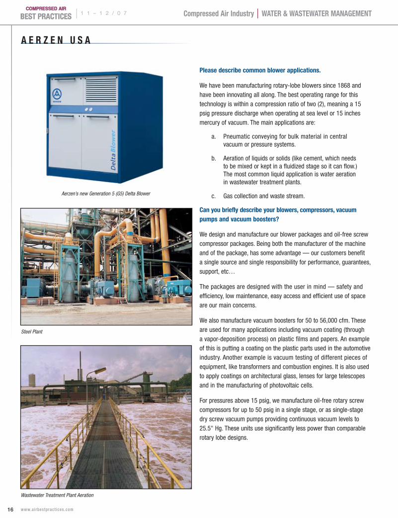
Please describe common blower applications.
We have been manufacturing rotary-lobe blowers since 1868 and have been innovating all along. The best operating range for this technology is within a compression ratio of two (2), meaning a 15 psig pressure discharge when operating at sea level or 15 inches mercury of vacuum. The main applications are:
a. Pneumatic conveying for bulk material in central vacuum or pressure systems.
b. Aeration of liquids or solids (like cement, which needs to be mixed or kept in a fluidized stage so it can flow.) The most common liquid application is water aeration in wastewater treatment plants.
c. Gas collection and waste stream.
Can you briefly describe your blowers, compressors, vacuum pumps and vacuum boosters?
We design and manufacture our blower packages and oil-free screw compressor packages. Being both the manufacturer of the machine and of the package, has some advantage — our customers benefit a single source and single responsibility for performance, guarantees, support, etc…
The packages are designed with the user in mind — safety and efficiency, low maintenance, easy access and efficient use of space are our main concerns.
We also manufacture vacuum boosters for 50 to 56,000 cfm. These are used for many applications including vacuum coating (through a vapor-deposition process) on plastic films and papers. An example of this is putting a coating on the plastic parts used in the automotive industry. Another example is vacuum testing of different pieces of equipment, like transformers and combustion engines. It is also used to apply coatings on architectural glass, lenses for large telescopes and in the manufacturing of photovoltaic cells.
For pressures above 15 psig, we manufacture oil-free rotary screw compressors for up to 50 psig in a single stage, or as single-stage dry screw vacuum pumps providing continuous vacuum levels to 25.5" Hg. These units use significantly less power than comparable rotary lobe designs.
Aerzen’s new Generation 5 (G5) Delta Blower
Wastewater Treatment Plant Aeration
Steel Plant
A e r z e n U s A
1 1 – 1 2 / 0 7 |
17 www.ai rbestpract ices .com
Compressed Air Industry | WATer & WAsTeWATer mAnAgemenT
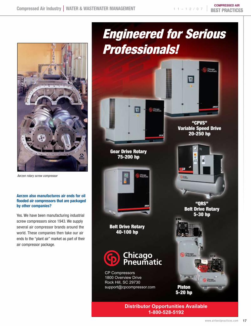
CP Compressors1800 Overview DriveRock Hill, SC [email protected]
Distributor Opportunities Available1-800-528-5192
Aerzen also manufactures air ends for oil flooded air compressors that are packaged by other companies?
Yes. We have been manufacturing industrial screw compressors since 1943. We supply several air compressor brands around the world. These companies then take our air ends to the “plant air” market as part of their air compressor package.
Aerzen rotary screw compressor
| 1 1 – 1 2 / 0 7
18 www.ai rbestpract ices .com
Compressed Air Industry | WATer & WAsTeWATer mAnAgemenT
Are you seeing a growing trend towards variable speed drives?
Some companies are in love with VSD’s. Demand is increasing and it is a good thing. We have applied VSD’s to blowers and screw compressor systems for several decades. Some are integrated in packages or locally installed. However, it is not always best to put it next to the machine. Many electricians like to have it in the clean and air-conditioned EMCC room. We see demand for VSD’s in water aeration applications; however, some applications only need on/off controls. As compelling as the use of a VSD is, it has its own efficiency and power loss, and is another piece of equipment. Again, we always discover benefits when we engage engineers in discussions about efficiencies in the beginning phase. Some have a mind-set for other technologies such as centrifugal blowers, which are very efficient at their design point. However, there are efficiency drawbacks when operating away from that design point.
What recommendations do you have for engineers?
The most important recommendation is for them to understand what the true need is and engage a trustworthy supplier in meeting that need. A need is never “a blower” or “a compressor” but rather a certain flow of air or gas under certain conditions and at a certain time. Offering solutions to best meet that need is our task. Typical in this context is the subject of noise level specifications. A machine room will be of a certain size and the factory wants to meet the OSHA requirements in the room. We often see a certain noise pressure level being specified emitted by the machine under free field conditions (meaning each machine is at Lp(A) =72 dB(A), for example). But what will be the noise level in the machine room? So we encourage our customers to engage us in a collaborative approach — to design the room (including the equipment), to meet their needs.
What are your feelings on centralized vs. decentralized blower and vacuum systems?
Each situation requires a unique solution. Decentralized systems are near the point of use, which results in less piping and lower pressure drops. Pneumatic conveying needs the right velocity of air to pick up the powder or granular matter and move it through a pipe. If the machine is far away, you may need a pretty long pipe to get it there in a centralized system. Some plants have their blowers in one room. In some cases, they could benefit from a machine at the point of use, with the proper acoustic hood. They can be located near offices, near neighbors or near workers. By placing machines near the point of use, piping can be reduced and less power is needed.
There are advantages in centralized systems, for example in some printing or paper processing facilities. Vacuum and pressure require-ments often exist right alongside where many people are working. If many decentralized small vacuum pumps/blowers are used, their efficiencies being relatively low, these small machines will introduce lots of heat into the area. Removing that heat by using air conditioning systems in turn consumes a lot of electricity. A central vacuum system requires a good piping system, but with good ventilation, it does not require or minimizes the need for air conditioning. Exhaust air can be ducted out of the plant or recovered. The overall power can also be reduced with the use of single stage rotary screw machine.
How about your responsibilities to the environment?
We not only encourage the use of energy-efficient equipment, we also believe our operating facilities should be environmentally friendly. We are just now moving into a new headquarters facility, which will hopefully meet the Gold LEED standard. To create this green building, we again used our philosophy of engaging employees
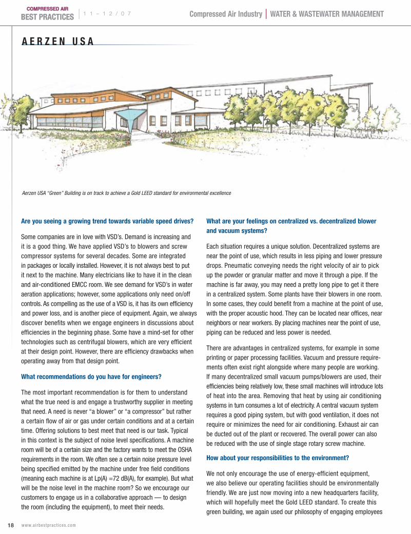
Aerzen USA “Green” Building is on track to achieve a Gold LEED standard for environmental excellence
A e r z e n U s A
1 1 – 1 2 / 0 7 |
19 www.ai rbestpract ices .com
Compressed Air Industry | WATer & WAsTeWATer mAnAgemenT
FROM LITTLE TO BIG ANDEVERYTHING IN BETWEEN
• Air & Gas Compressors and Boosters• 3 to 206 SCFM• Pressures to 6000 PSI• 3 to 125 Horsepower• Sound Attenuated Enclosures Available• Standard and Custom Designs• Mobile Designs Available
BAUER COMPRESSORS Inc.Telephone: 757-855-6006 • Telefax: 757-857-1041E-Mail: [email protected] • www.bauercomp.com/norfolk/industrialair
and vendors together in a dialogue to accomplish our goals. If people work together holistically, ideas can build upon another.
We did a design retreat and brought together the architects, landscape architects, civil engineers, structural engineers, HVAC engineering firms, crane manufacturers for overhead cranes, fire chief to meet code, employees, and lean manufacturing consultants. By bringing everyone together we brought out all the best ideas and are excited about the results. Bringing light and warmth into our work unfreezes creativity. The financial results are used as a measurement of our success, not as an end in themselves. At Aerzen we believe it is our responsibility to live by these standards in our own operations and with our customers.
Thank you Aerzen for your insights.
For more information please contact Ralph Wilton, tel: 484-288-6367, email: [email protected], www.aerzenusa.com
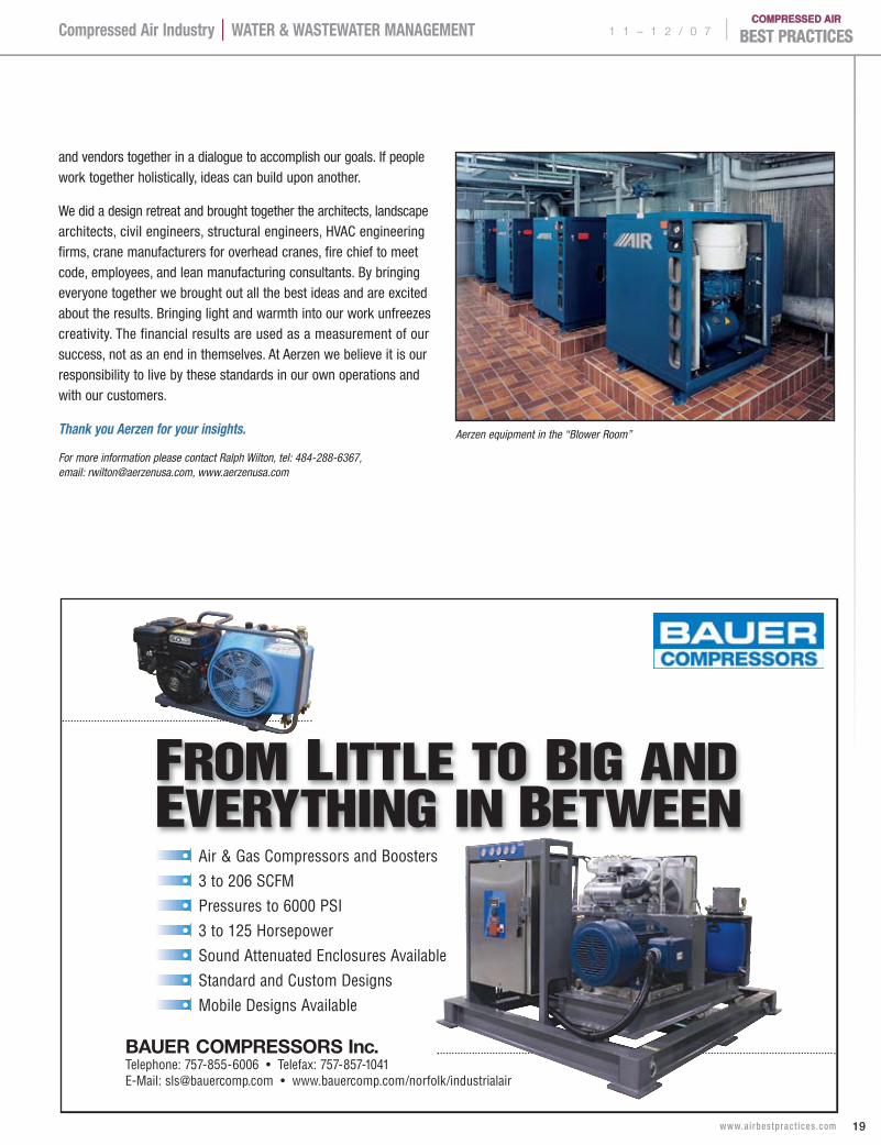
Aerzen equipment in the “Blower Room”
Focus Industry | WATer & WAsTeWATer mAnAgemenT | 1 1 – 1 2 / 0 7
20 www.ai rbestpract ices .com
C r i t i C a l C o m p r e s s e d a i r t r e a t m e n t f o r a n a s C a r W i n d t u n n e lBY grAHAm WHITmOre
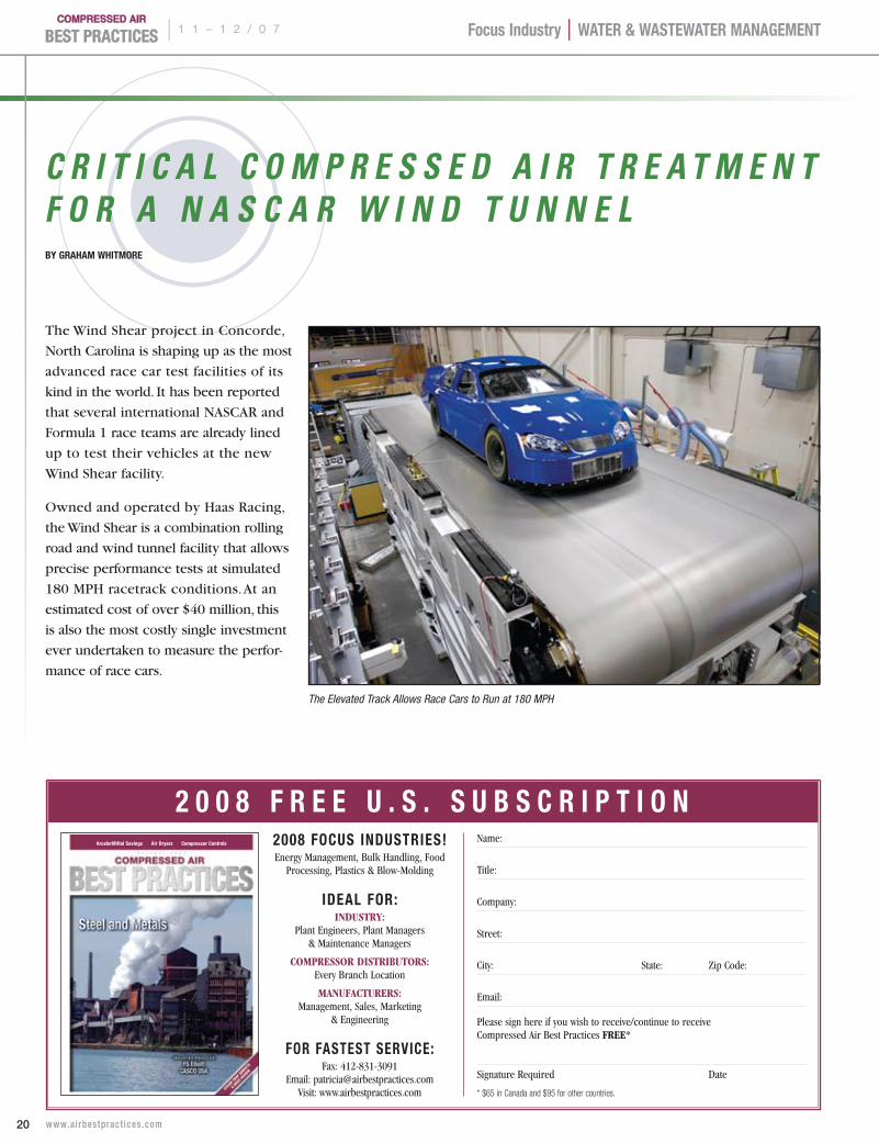
The Wind Shear project in Concorde,
North Carolina is shaping up as the most
advanced race car test facilities of its
kind in the world. It has been reported
that several international NASCAR and
Formula 1 race teams are already lined
up to test their vehicles at the new
Wind Shear facility.
Owned and operated by Haas Racing,
the Wind Shear is a combination rolling
road and wind tunnel facility that allows
precise performance tests at simulated
180 MPH racetrack conditions. At an
estimated cost of over $40 million, this
is also the most costly single investment
ever undertaken to measure the perfor-
mance of race cars.
The Elevated Track Allows Race Cars to Run at 180 MPH
2008 FOCUs InDUsTrIes!Energy Management, Bulk Handling, Food
Processing, Plastics & Blow-Molding
IDeAl FOr:Industry:
Plant Engineers, Plant Managers & Maintenance Managers
Compressor dIstrIbutors: Every Branch Location
manufaCturers: Management, Sales, Marketing
& Engineering
FOr FAsTesT servICe: Fax: 412-831-3091
Email: [email protected]: www.airbestpractices.com
Name:
Title:
Company:
Street:
City: State: Zip Code:
Email:
Please sign here if you wish to receive/continue to receive Compressed Air Best Practices free*
Signature Required Date
* $65 in Canada and $95 for other countries.
O c t o b e r 2 0 0 7
ArcelorMittal Savings Air Dryers Compressor Controls
2 0 0 8 F r e e U . s . s U B s C r I P T I O n
Focus Industry | WATer & WAsTeWATer mAnAgemenT 1 1 – 1 2 / 0 7 |
21 www.ai rbestpract ices .com
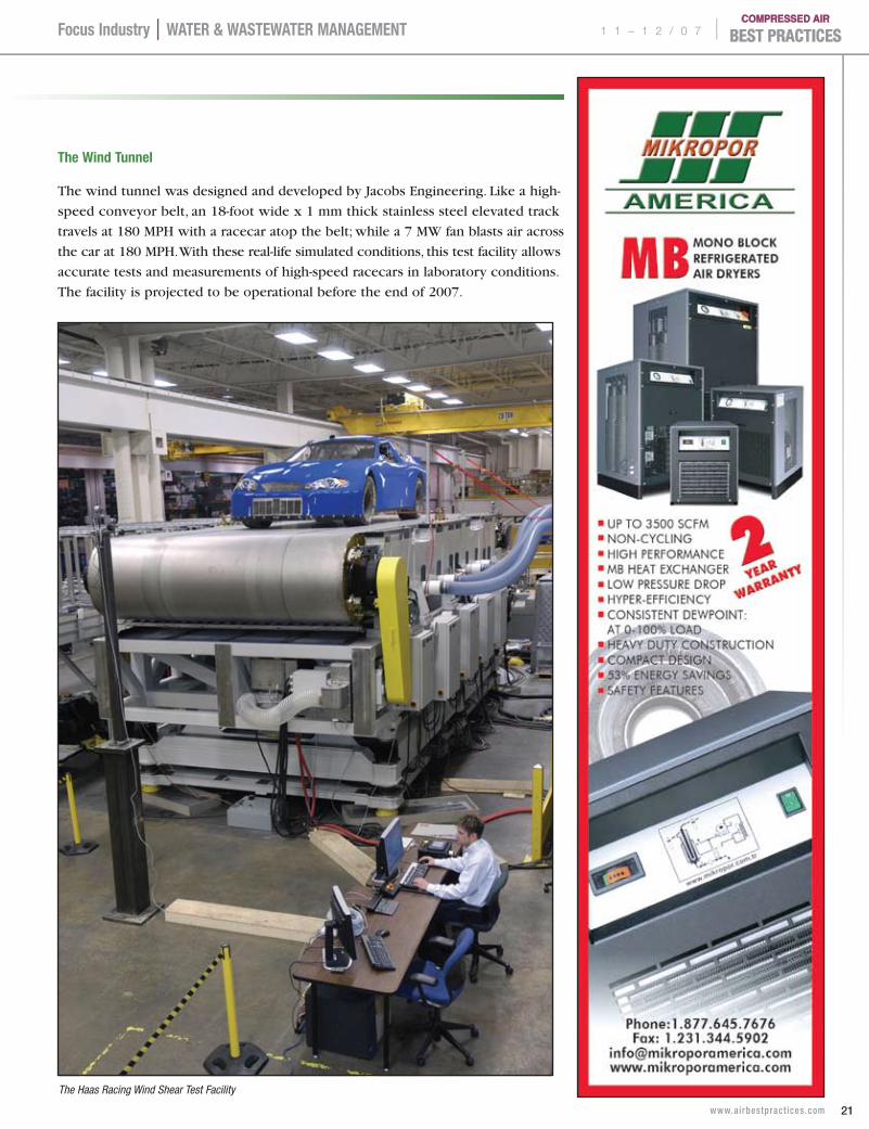
The Wind Tunnel
The wind tunnel was designed and developed by Jacobs Engineering. Like a high-
speed conveyor belt, an 18-foot wide x 1 mm thick stainless steel elevated track
travels at 180 MPH with a racecar atop the belt; while a 7 MW fan blasts air across
the car at 180 MPH. With these real-life simulated conditions, this test facility allows
accurate tests and measurements of high-speed racecars in laboratory conditions.
The facility is projected to be operational before the end of 2007.
The Haas Racing Wind Shear Test Facility
Focus Industry | WATer & WAsTeWATer mAnAgemenT | 1 1 – 1 2 / 0 7
22 www.ai rbestpract ices .com
The suspension and tire test measure-
ment equipment is almost entirely
pneumatic, which allows increased
flexibility and accuracy. This system
requires large quantities of instrument-
quality compressed air, which must
be controlled at a precise dew point
and temperature, 24 x 365 for testing
at any time of the day or night on
a year-round basis.
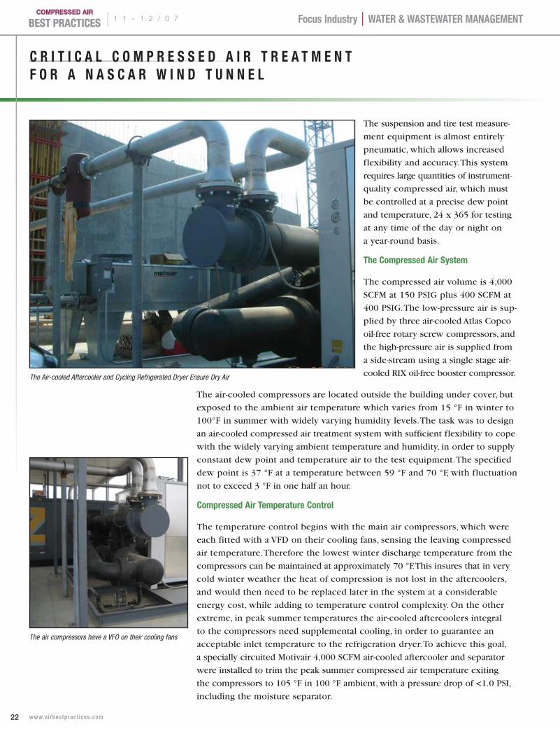
The Compressed Air system
The compressed air volume is 4,000
SCFM at 150 PSIG plus 400 SCFM at
400 PSIG. The low-pressure air is sup-
plied by three air-cooled Atlas Copco
oil-free rotary screw compressors, and
the high-pressure air is supplied from
a side-stream using a single stage air-
cooled RIX oil-free booster compressor.
The air-cooled compressors are located outside the building under cover, but
exposed to the ambient air temperature which varies from 15 °F in winter to
100°F in summer with widely varying humidity levels. The task was to design
an air-cooled compressed air treatment system with sufficient flexibility to cope
with the widely varying ambient temperature and humidity, in order to supply
constant dew point and temperature air to the test equipment. The specified
dew point is 37 °F at a temperature between 59 °F and 70 °F, with fluctuation
not to exceed 3 °F in one half an hour.
Compressed Air Temperature Control
The temperature control begins with the main air compressors, which were
each fitted with a VFD on their cooling fans, sensing the leaving compressed
air temperature. Therefore the lowest winter discharge temperature from the
compressors can be maintained at approximately 70 °F. This insures that in very
cold winter weather the heat of compression is not lost in the aftercoolers,
and would then need to be replaced later in the system at a considerable
energy cost, while adding to temperature control complexity. On the other
extreme, in peak summer temperatures the air-cooled aftercoolers integral
to the compressors need supplemental cooling, in order to guarantee an
acceptable inlet temperature to the refrigeration dryer. To achieve this goal,
a specially circuited Motivair 4,000 SCFM air-cooled aftercooler and separator
were installed to trim the peak summer compressed air temperature exiting
the compressors to 105 °F in 100 °F ambient, with a pressure drop of <1.0 PSI,
including the moisture separator.
C r I T I C A l C O m P r e s s e D A I r T r e A T m e n T F O r A n A s C A r W I n D T U n n e l
The Air-cooled Aftercooler and Cycling Refrigerated Dryer Ensure Dry Air
The air compressors have a VFO on their cooling fans
Focus Industry | WATer & WAsTeWATer mAnAgemenT 1 1 – 1 2 / 0 7 |
23 www.ai rbestpract ices .com
Cycling refrigerated Dryers
The compressed air then enters the
Motivair cycling 4,000 SCFM refrig-
eration dryer. This dryer design was
selected because of its thermal storage
capacity and the dryer’s passive ability
to “iron out” temperature fluctuations,
especially under varying load and inlet
temperatures. This is achieved with the
built-in 135 gallon glycol storage reser-
voir, which acts as an effective thermal
buffer. This dryer is capable of very
close dew point control, because of its
exclusive heat exchanger surface and
extremely high efficiency 2-stage stain-
less steel coalescing moisture separator,
capable of 99.9% efficiency from zero
to 100% of rated airflow. Close dew
point control is further insured by the
use of a VFD on the dryer’s condenser
fans to provide a constant refrigerant
head pressure under varying outside
ambient temperatures.
The final dew point and temperature
control in the dryer is provided by a
Pulse Width Modulation (PWM) hot gas
injection valve that maintains the chilled
glycol and therefore the dew point at
± 1°F. All of the dryer’s control and alarm
functions are provided by a custom PLC
system designed specifically for this
purpose. At this point the leaving air can
be considered dry within the tolerances
of the dew point and temperature speci-
fication. The dried air passes through
a 5,300 gallon receiver, multi-element
filter and demand expander, designed
to optimize compressed air pressure and
compressor operation, before entering
the building.
Trim Cooler and Heater Provide extra Insurance
As further insurance against temperature
(not dew point) deviation from set point
in extreme summer or winter ambient
temperatures, an in-line trim cooler
and trim heater were installed in series
inside the building and prior to the air
being delivered to the Rolling Road
pneumatic test equipment. The trim
cooler is a Motivair 4,000 SCFM shell
and tube aftercooler, fed by a close-
control air-cooled Motivair water chiller.
The chiller is (similar to the main dryer)
fitted with a VFD on the condenser fans
and a PWM hot gas injection valve
to maintain extremely close control
of the compressed air temperature in
peak summer. A motorized 3-way valve,
controlled by a proportional tempera-
ture controller sensing the final leaving
compressed air temperature determines
exactly how much chilled water is
required in the trim aftercooler, in
order to keep the air at the desired
temperature. The trim heater is a pres-
sure vessel with a sheathed electrical
heater inside, controlled by a micro-
processor with a PID loop, sensing the
leaving air temperature. Heat is applied
in very small increments by an SCR
power controller in order to avoid
“overshooting” the temperature control
range in the lowest winter operating
temperatures. The final conditioned
compressed air supply is fitted with
calibrated temperature gauges and
a hygrometer (direct-reading dew
SaveThousands in Compressed Air Waste. Go Green.
ULTRASOUND ADVICE
Now is the perfect time to protect the environment while saving significant production dollars annually. Poorly maintained compressed air systems cost companies thousands annually in energy waste. With Ultrasound Condition Monitoring, learn how you can immediately begin to cut energy waste while gaining buyers respect and support.
ADVANCED ULTRASONIC TECHNOLOGY ° CERTIFIED TRAINING COURSES ° WORLD-CLASS SERVICE & SUPPORT
Log onto UESOUNDADVICE.COM for more info and
recieve a FREE sample pack of compressed air leak tags!
Join UE Systems at Ultrasound World IV! January 27-30, 2008
Clearwater Beach, Florida Learn how ultrasound condition
monitoring can help reduce energy waste.
Focus Industry | WATer & WAsTeWATer mAnAgemenT | 1 1 – 1 2 / 0 7
24 www.ai rbestpract ices .com
C r I T I C A l C O m P r e s s e D A I r T r e A T m e n T F O r A n A s C A r W I n D T U n n e l
point meter) to offer the customer com-
plete assurance of compliance within the
optimum instrument operating range.
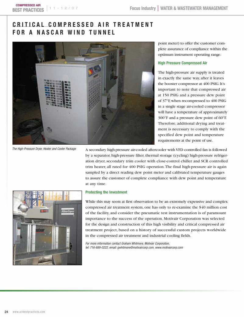
High Pressure Compressed Air
The high-pressure air supply is treated
in exactly the same way, after it leaves
the booster compressor at 400 PSIG. It’s
important to note that compressed air
at 150 PSIG and a pressure dew point
of 37°F, when recompressed to 400 PSIG
in a single stage air-cooled compressor
will have a temperature of approximately
300°F and a pressure dew point of 60°F.
Therefore, additional drying and treat-
ment is necessary to comply with the
specified dew point and temperature
requirements at the point of use.
A secondary high-pressure air-cooled aftercooler with VFD controlled fan is followed
by a separator, high-pressure filter, thermal storage (cycling) high-pressure refriger-
ation dryer, secondary trim cooler with close-control chiller and SCR controlled
trim heater, all rated for 400 PSIG operation. The final high-pressure air is again
sampled by a direct reading dew point meter and calibrated temperature gauges
to assure the customer of complete compliance with dew point and temperature
at any time.
Protecting the Investment
While this may seem at first observation to be an extremely expensive and complex
compressed air treatment system, one has only to re-examine the $40 million cost
of the facility, and consider the pneumatic test instrumentation is of paramount
importance to the success of the operation. Motivair Corporation was selected
for the design and construction of this high visibility and critical compressed air
treatment project, based on a history of successful custom projects worldwide
in the compressed air treatment and industrial cooling fields.
For more information contact Graham Whitmore, Motivair Corporation, tel: 716-689-0222, email: [email protected], www.motivaircorp.com
The High-Pressure Dryer, Heater and Cooler Package
25 www.ai rbestpract ices .com
1 1 – 1 2 / 0 7 |Focus Industry | WATer & WAsTeWATer mAnAgemenT
C O m P r e s s e D A I r P I P I n g
The subject of compressed air piping has probably had more pages written about it than any other topic, even storage. Like many other topics in “practical” compressed air technology, a significant portion of this is controversial and often directly opposed.
These best practice guidelines are not designed to replace the appropri-ate correct volumes of information and are not designed to answer all questions regarding a specific installation. They are designed to arm you with basic principles that always apply and when followed, will end up with a well performing system. As with all our best practice guidelines, they are based on performance and measured critical data in the field molded with theoretical performance. We have developed and used these guidelines over the last 20 years and find them very accurate.
Types of Piping Offered For Compressed Air
Consult Federal, State and Local codes before deciding on the type of piping to be used. The usual standard to be applied to ANSI B31.1. For health care facilities, consult the current Standard NFPA 99 of the National Fire Protection Association.
The compressed air piping materials can be divided into two basic types: Metal and Non-metal.
Non-Metal Pipe — commonly called “plastic” pipe, has been offered for many years as compressed air piping because:
p It is lighter than most metal and easier to handle.
p It can be installed with no special tools (such as welders, threaders, etc).
p It is generally non-corrosive.
p Installation with the appropriate gluing material is fast.
p The labor (which can also be unskilled) is less costly than most metals (copper, stainless, black iron), and the total job may often be less expensively installed.
What has held back this material’s acceptance by many compressed air people and organizations?
Early on, PVC was used for compressed air piping. It was not long before the fact that it sometimes “shattered” and failed, sending sharp pieces throughout the area. This became evident. New products were introduced that utilized material that did not shatter. However, this material and all others offered to date have two significant limitations:
p Most of these are limited to an operating temperature of 140 ˚F to 200 ˚F. The failure in an aftercooler can easily reach or exceed these numbers. PVC, for instance, is limited to about 160 ˚F at 125 psig, but it actually starts to weaken at 70 ˚F.
p Most of these materials are not compatible with compressor oils in general and particularly many synthetics.
p Although pipeline fires are rare today, when there is one in plastic pipe, there is a good chance that it will melt through the plastic pipe and migrate into the plant.
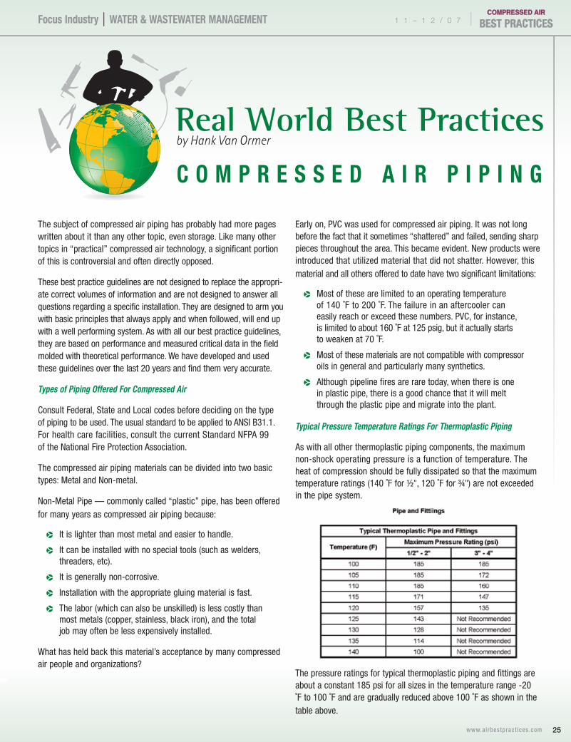
Typical Pressure Temperature Ratings For Thermoplastic Piping
As with all other thermoplastic piping components, the maximum non-shock operating pressure is a function of temperature. The heat of compression should be fully dissipated so that the maximum temperature ratings (140 ˚F for ½", 120 ˚F for ¾") are not exceeded in the pipe system.
The pressure ratings for typical thermoplastic piping and fittings are about a constant 185 psi for all sizes in the temperature range -20 ˚F to 100 ˚F and are gradually reduced above 100 ˚F as shown in the table above.
C O m P r e s s e D A I r P I P I n g
www.ai rbestpract ices .com26
Focus Industry | WATer & WAsTeWATer mAnAgemenT | 1 1 – 1 2 / 0 7
Overall, the compressed air industry has not accepted any type of “plastic” pipe as appropriate and safe for down-stream compressed air. As a consultant, we would agree with this given today’s available material, data and available alternatives.
metal Pipe — can be black iron, stainless steel, copper, aluminum, etc. with proper thermal/pressure characteristics.
Black Iron or Steel Pipe — in compressed air systems will corrode when exposed to condensate (H2O) and thus become a major source of contamination to the whole system. This pipe is usually threaded connected 3" diameter and smaller, welded with larger diameters. Compared to copper and aluminum, it is much heavier and harder to work with, but less expensive. The internal corrosion issue is much more significant with oil- free air than with lubricated compressors.
Stainless Steel — is often a good selection particularly when exposed to oil-free wet air and its extremely high acid level condensate (before the dryers). Stainless steel is often lighter for the same pressure temperature rating and installs well when welded. Threaded stainless steel often tends to leak. Ring seals such as those used in Victaulic connections will work well here. As piping material however, the potential lower installation cost and faster welding (use of Victaulic* fittings) may well make it the most overall economical.
Copper Pipe — is a common selection for sensitive air systems. When selected and connected correctly it is very rugged. The working pressure of copper piping is 250 psi for Type “M” hard, Type “L” hard and Type “K” soft and 400 psi for Type “K” hard. Further, since 50/50 solder melts at 421 ˚F, it will be more resistant to high temperatures. Even if it does fail, it will do so in a predictable manner. The pipe ends will separate. The working temperature limit of copper piping is about 400 ˚F. (Data from Piping Handbook, 6th edition).
Aluminum compressed air pipe as applied today has become very popular. This has been developed not only to provide smooth (low pressure loss due to friction) inner surface and eliminate “self contamination,” but also to offer enhanced flexibility to meet the ever-changing compressed air distribution needs. This is particularly desirable in the automotive support industry with changing assembly and sub-assembly areas.
Most of the aluminum pipe manufacturers rate their material at +4 ˚F to 140 ˚F or 176 ˚F. The piping material usually has a melting point of over 1,100 ˚F.
Victaulic Connections are simple systems:
p Cut to size and groove the pipe on-site, no threading required.
p Bolted assembly is fast and flameless with positive seal.
p Victaulic fittings can be used with almost any metal pipe.
Other Questions on material and Optimal Coatings for Inlet Air Piping and Discharge Air Piping
The question of galvanized piping comes up often in compressed air system piping instead of schedule 40 black iron for the nominal 100 psig air systems. To help evaluate this, let’s look at inlet and dis-charge piping separately.
General Guidelines For Inlet Piping
The proper inlet pipe brings the air from the filter to the compressor with no pressure loss, and should not create operational problems with any type of self-contamination on the inside. It is important to realize that the ambient inlet air condition may well dictate the selection of one type of pipe over another.
galvanized inlet piping has the advantage of resisting corrosion better than standard iron pipe. However, overtime when the corrosion does set in, the galvanizing material peels off. The inlet pipe is now a producer of potentially very damaging, solid contaminants between the filter and the compressor. This would be particularly dangerous to the mechanical integrity of a centrifugal compressor. We do not recommend this.
During high-humidity weather it is quite conceivable that condensation will form in the inlet pipe (therefore, the OEM installation manual usually recommends a drain valve be installed on the pipe before the inlet). Condensation in the pipe will obviously accelerate the time frame before the coating breaks down. This time frame is dependent upon where the thinnest portion of the coating is applied.
stainless steel inlet pipe is an excellent material for such large-diameter, low-pressure inlet air, as long as it is installed properly and the inside is properly cleaned.
There are also many grades of thermoplastic material suitable for inlet air piping.
summary: We recommend either stainless steel or proper thermoplastic-type material for inlet piping and do not recommend galvanized piping.
extruded Aluminum
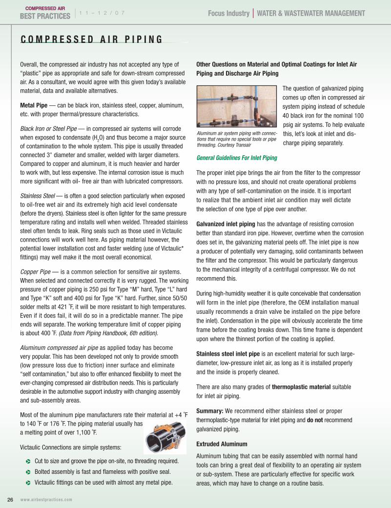
Aluminum tubing that can be easily assembled with normal hand tools can bring a great deal of flexibility to an operating air system or sub-system. These are particularly effective for specific work areas, which may have to change on a routine basis.
Aluminum air system piping with connec-tions that require no special tools or pipe threading. Courtesy Transair
27 www.ai rbestpract ices .com
1 1 – 1 2 / 0 7 |Focus Industry | WATer & WAsTeWATer mAnAgemenT
Discharge and Distribution Piping
Here we have more complex considerations:
The discharge air from the compressors can be at 250 to 350 ˚F (for centrifugal, oil-free rotary screw and reciprocating types), or from 200 to 220 ˚F (for lubricant-cooled rotary screw compressors), so the pipe must be able to withstand those temperatures.
Even if there is an aftercooler that drops the temperature to 100 ˚F, consideration must be given to the consequences if the aftercooler were to fail.
Compressed air-generated condensate tends to be acidic. In oil-free compressors (such as centrifugals and oil-free rotary screws), it is usually very aggressive.
The basic objective of the interconnecting piping is to deliver the air to the filters and dryers and then to the production air system with little or no pressure loss, and certainly with little or no self-contamination.
Galvanized piping will have the same problems once it begins to peel, as we described on the inlet application. In all probability, due to the aggressive acid characteristics of the condensate, the galvanized coating life may be much shorter.
Regardless of the thermoplastic pipe manufactures claims; we never recommend any plastic type material for interconnecting piping and rarely for distribution header piping. Most of these materials carry cautions not to be exposed to temperatures over 200 ˚F and to avoid any types of oil or lubricants.
Here again, stainless steel is our number one recommendation for the interconnecting piping from the compressor to the filter/dryers when the compressed air is oil-free. It will obviously resist corrosion much better than standard schedule 40 black iron. Some other considerations:
Most areas will allow schedule 10 stainless steel in lieu of schedule 40 black iron.
For the same diameter pipe, stainless steel will be much lighter and easier to handle, usually lowering the labor cost.
For welded connections, stainless steel usually just requires one bead, while black iron pipe usually requires three beads (Weld-fill-cover). This should also lower the labor cost.
Stainless steel does not usually seal well when threaded. It will do much better with Victaulic type connections when welding is not practical.
summary
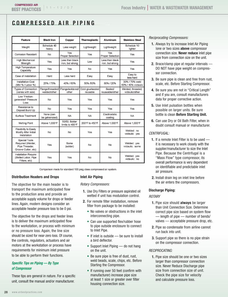
The following comparison chart summarizes some of the pros and cons of each type of piping material. This information has come from discussions with piping manufacturers, mechanical contractors and plant personnel along with years of system analysis by airfield personnel.
C O m P r e s s e D A I r P I P I n g
28 www.ai rbestpract ices .com
Focus Industry | WATer & WAsTeWATer mAnAgemenT | 1 1 – 1 2 / 0 7
Distribution Headers and Drops
The objective for the main header is to transport the maximum anticipated flow to the production area and provide an acceptable supply volume for drops or feeder lines. Again, modern designs consider an acceptable header pressure loss to be 0 psi.
The objective for the drops and feeder lines is to deliver the maximum anticipated flow to the workstation, or process with minimum or no pressure loss. Again, the line size should be sized for near-zero loss. Of course, the controls, regulators, actuators and air motors at the workstation or process have requirements for minimum inlet pressure to be able to perform their functions.
Specific Tips on Piping — By Type of Compressor
These tips are general in nature. For a specific unit, consult the manual and/or manufacturer.
Inlet Air Piping
Rotary Compressors:
1. Use Dry Filters or pressure aspirated oil wetted if unit has modulation control.
2. For remote filter installation, remove filter from package to be installed:
• No valves or obstructions in the inlet interconnecting pipe.
• Can use supported flex/rubber hose to pipe outside enclosure to connect to Inlet Pipe.
• If inlet is outside — be sure to install a bird deflector.
• Support Inlet Piping — do not hang on the unit.
• Be sure pipe is free of dust, rust, weld beads, scale, chips, etc. Before Starting the Compressor.
• If running over 50 feet (confirm with manufacturer) increase pipe size at least 1 size or greater over filter housing connection size.
Reciprocating Compressors:
1. Always try to increase Inlet Air Piping |one or two sizes above compressor connection size. never reduce inlet pipe size from connection size on the unit.
2. Brace/clamp pipe at regular intervals — DO NOT have pipe weight on compres-sor connection.
3. Be sure pipe is clean and free from rust, scale, etc. Before Starting Compressor.
4. Be sure you are not in “Critical Length” and if you are, consult manufacturers data for proper corrective action.
5. Use Inlet pulsation bottles when possible on larger units. Be sure bottle is clean Before starting Unit.
6. Can use Dry or Oil Bath Filter, when in doubt consult manual or manufacturer.
CENTRIFUGAL:
1. If a remote Inlet Filter is to be used — it is necessary to work closely with the supplier/manufacturer to size the Inlet Pipe. Because the Centrifugal is a “Mass Flow” type compressor, its overall performance is very dependent on identifiable and predictable inlet air pressure.
2. Install drain leg on inlet line before the air enters the compressors.
Discharge Piping:
ROTARY
1. Pipe size should always be larger than Unit Connection Size. Determine correct pipe size based on system flow — length of pipe — number of bends/valves — acceptable pressure drop, etc.
2. Pipe so condensate from airline cannot run back into unit.
3. Support pipe so there is no pipe strain on the compressor connection.
RECIPROCATING:
1. Pipe size should be one or two sizes larger than compressor connection size. Never Reduce Discharge pipe size from connection size of unit. Check the pipe size for velocity and calculate pressure loss.

1 1 – 1 2 / 0 7 |Focus Industry | WATer & WAsTeWATer mAnAgemenT
2. Brace/Clamp pipe at regular intervals. DO NOT have pipe strain on compres-sor connection.
3. Be sure you are not in “Critical Length.” If you are, consult manual/ or manufac-turer for proper corrective action.
4. Use Discharge Pulsation bottles when possible on larger units.
CENTRIFUGAL:
1. Refer to the manual/manufacture for detailed location of check valves, back valves, safety valves, etc.
2. Discharge piping should be larger than the compressor connection and should have a smooth run directly away from the unit.
3. All turns should be “Long Sweep Ells” to allow a minimum of backpressure. This is always recommended in any air system but it is much more critical in a “mass flow” centrifugal.
4. All piping should slope away from the compressor. All risers should have drain legs. Install a drain leg immediately after the compressor in the Discharge Line.
Interconnecting Piping With Multiple Units
Interconnecting Piping Configuration — between the compressor discharge through the air treatment equipment and storage before entering the storage area.
Over the years, we have found very few plants where the interconnecting piping does not cause control problems with multiple units. This usually leads to multiple units at part load (poor basic efficiency), step controlled units with “extreme” short cycling, can have very poor efficiency and lead to premature failure of operating components.
The objective in sizing interconnecting piping is to transport the maximum expected air flow from the compressor discharge through the dryers, filters and receivers to the main distribution header with minimum pressure drop. Contemporary designs that consider the true cost of compressed air target a total pressure drop of less than 3 psi.
The interconnecting piping should be sized with regard to velocity rather than friction loss only; avoiding such things as high turbulence and its resistance to flow with
resultant pressure spikes and loss. Design configuration has significant impact on this also. All pipeline velocities are to be 20 fps or less at 100 psig. At these velocities, even some poor piping configuration practices will have much less negative impact.
General Guidelines All Piping
All air (and water) inlet and discharge pipes to and from the inlet and discharge connection of the air compressor must take into account — vibration, pulsations, temperature exposure, maximum pressure exposed to, corrosion and chemical resistance, etc. In addition, lubricated compressors will always discharge some oil into the air stream, and compatibility of the discharge piping and other accessories (such as O-rings, seals, etc.) with both petroleum and/or synthetic lubricants is critical.
Good Avoid
29 www.ai rbestpract ices .com
30 www.ai rbestpract ices .com
| 1 1 – 1 2 / 0 7 Focus Industry | WATer & WAsTeWATer mAnAgemenT
General Rules For Compressed Air Distribution System
1. Pressure drop between the compressor and point of use is irrecoverable.
2. Pipe size should be large enough that pressure drop is held to a minimum. There is no reason to tolerate any pressure loss during normal operation in Header Distribution.
3. Arrange piping to avoid the following types of strains:
A. Strains due to dead weight of the pipe itself.
B. Strains due to expansion or contraction of the piping with temperature change.
C. Strains due to internal pressure within the piping.
4. Design inlet and discharge piping for smooth flow with uniform trans-lateral velocity over the entire area of the piping.
5. Install safety valve between compressor and shut-off valve (5 to 10 PSI above compressor operating pressure). Never exceed the working pressure rating of an ASME vessel in the system.
6. Plan for future emergencies and establish a tie-in point to install temporary compressor with power and aftercooler (if required).
7. Consider bypass lines or valves on all items that may require future maintenance.
8. Use loop design system if possible, both around the plant and within each production zone.
9. Consider a second air receiver at end of line or loop only if you have peak demands for air near that point.
10. Locate outlets from the main header as close as possible to point of application. This helps limit large pressure drops through hose.
11. Outlets should always be taken from the top of pipeline to alleviate carryover of condensed moisture to tools.
12. All piping should be sloped so that it drains toward a drop leg moisture trap or receiver away from the compressor and/or process.
Flexible connections should be used to reduce or absorb vibration and mitigate the effect of thermal expansion. They should not Be Used To Correct misalignments. Any Flex connection used should be investigated to be sure its specification fits the operating parameters of the system.
“It is important to note that improper or incorrectly applied piping and material in an AIR SYSTEM can result in Mechanical Failure; Damage; and Serious Injury or Death”.
Summary:
1. If proper copper piping is used, be sure the solder used has the proper characteristics to handle the anticipated temperatures at Full Load.
2. Use of Plastic Piping (PvC). There are many negatives that have accumulated over the years around the use of PLASTIC (PVC) piping.
• Lack of resistance to failure due to fatigue caused by vibration.
• Lack of resistance to softening crazing, cracking & from lubricants — particularly Diester synthetics.
• Susceptibility to a Catastrophic Failure results from something like an Aftercooler Failure.
• Potential Catastrophic Failure caused by an outside fire.
• Potential Catastrophic Failure from a Pipeline Fire or Detonation.
• Potential to be attacked from outside or within from Airborne Chemicals and Condensate (inside).
• A failure in Plastic or PVC pipe under pressure may Explode or Shatter, endangering personnel in the area.
3. New Types of Plastic Piping and Valves
There have been new product introduc-tions of “Plastic Piping System” which claim to have solved most of the negative problems including the “Shattering Characteristics.” “NEW” plastic pipes are based on specially modified formulation or acrylo-nitrile butadiene styrene (ABs) resin.
4. Many people feel that any type of Non-Metallic (i.e. “Plastic”) Piping is a high risk because in any air system (particularly lubricated) the potential for a “pipeline fire” always exists. Even though it may be a most unlikely occurrence, plant safety is certainly enhanced if the “pipeline fire” stays in the pipe and does not burn through the wall.
C O m P r e s s e D A I r P I P I n g
31 www.ai rbestpract ices .com
1 1 – 1 2 / 0 7 |Focus Industry | WATer & WAsTeWATer mAnAgemenT
Poor Piping Configuration in Action
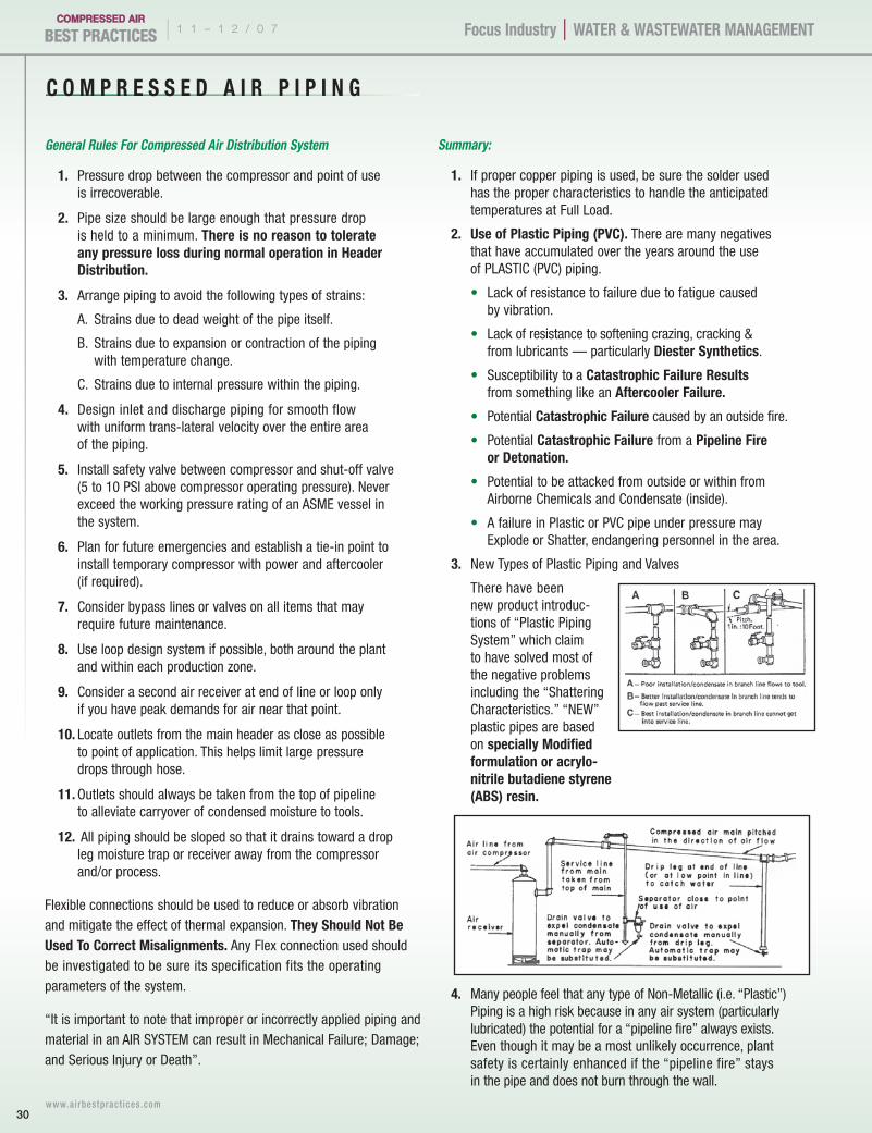
The plant was running four 100-hp lubricant-cooled rotary screw compressors under modulating control. It was losing productive capacity because a 20-psi pressure drop made it impossible to maintain the required minimum 90 psig in the header. The piping schematic in Figure 1 shows the original piping. Four 100-hp 490-cfm oil-cooled rotary screw compressors delivered air to a 6-in. main header. The velocity in the 4-in. interconnecting piping was as follows:
Four crossing tees added turbulence at these velocities. The total pressure loss with all machines at full load was 20 psig. When demand increased, the pressure in the main fell below 90 psig, shutting down production. Two changes solved the problem. First, the 4-in. crossing tees were changed to directional angle entry. The pressure drop fell to 6 psi and the main system now receives 104 psig that is easily regulated to a steady 90 psig. The connections were prefabricated and installed during a one-day maintenance shutdown at a cost of $4,200. This eliminated the production interruptions that had occurred for 20 years. Second, the compressor discharge pressure was reduced to 98 psig, which represents a power saving rate of six percent, equivalent to about $9,585 annually.
p 13.2 fps @ 490 cfm.
p 26.4 fps @ 980 cfm.
p 39.6 fps @ 1,470 cfm.
p 47.4 fps @ 1,760 cfm.
Figure 1: Before
Figure 2: After
the NewG5 DeltaBlower
SMALLERBETTERQUIETER
more energy savings=lowest lifecycle costs
AerzenUSA.com Click or call to see the new G-5 Delta Blower.
Keeping you one step ahead.
AERZEN USA Corporation645 Sands Court, Suite 100 Coatesville, PA 19320/USAPhone (610) 380-0244 � Fax (610) 380-0278 E-mail: [email protected]
� CONTINUOUS CONTROLS � COMPACT � EASY INSTALLATION
AND ACCESS
| 1 1 – 1 2 / 0 7 Compressed Air Industry | WATer & WAsTeWATer mAnAgemenT
32 www.ai rbestpract ices .com
A u d i t i n g f o r E n E r g y S A v i n g S w i t h
John henry Foster MinnesotaHistory
Since 1938, John Henry Foster Minnesota Inc.™ (JHF) has promoted a progressive culture by seeking opportunities for cutting edge technology and providing clients with exceptional value. Many of our employees have been with us for two to three decades. These employees have grown with the company and have acquired tremendous knowledge and experience over the years to address customers’ needs. Because employees at JHF are trained and practiced, we can obtain results. Dedication in taking care of our employees and providing clients with first-class service has been part of JHF for nearly 70 years.
Differentiators
The John Henry Foster Minnesota mission is to offer consultative sales versus commodity selling to our clients. By providing both capital equipment and pneumatic components consultatively, we have the ability to partner with both the supply side and demand side of compressed air systems. JHF is a leader in providing innovative solutions and consistent value to customers with this sales process and technical development. JHF is one of very few firms in the country that is structured to work with both sides of compressed air and has since the firm’s beginnings. Industries in the 1940’s were smaller and companies could sell both, but today companies either focus on one or the other due to difficulties in training staff and manufacturers who tend to team with distributors, who focus in their area of expertise.
We anticipate industry drivers of our customers to be the exclusive provider by bundling our services into a single point of contact. By anticipating the needs
of customers, JHF has expanded and further explored new areas, such as fluid cooling and vacuum markets. Another application we now focus on is identifying energy saving opportunities for clients, or an Air System Audit. In order to gather the appropriate information to complete an analysis, we work with both ends of the compressed air system; the supply of air and the use of air. Working with each touch point to find energy loss, JHF can determine corrective actions and opportunities on both the production floor and the compressor room. JHF was one of the first distributors in the country involved in Air System Audits; we created and designed our own equipment, wrote analysis software and customized electronic control and monitoring equipment — another example of our innovation and resourceful approach.
John Henry Foster Minnesota also brings this resourcefulness to our mobile service agreement program and differentiates us from other providers. This service increases our market share by allowing our expertise to be brought directly to the customers’ air compressor rooms and plants, enabling us to deliver a short response time to problems, installation support and preventative maintenance. We are also providing a local presence to the communities that we serve.
Ron Nordby from John Henry Foster Minnesota
(Contunied on page 36.)
1 1 – 1 2 / 0 7 |Compressed Air Industry | WATer & WAsTeWATer mAnAgemenT
33 www.ai rbestpract ices .com
INTRODUCTION
A large Midwestern packaging firm in business for more than 70 years providing corrugated containers to a wide range of industries, use compressed air to run their corrugators’ glue unit, offering just-in-time solutions to help customers keep their packaging costs to a minimum.
The packaging firm built a state-of-the-art facility in the 1990s to accommodate their growing business. While it served them well over the past decade, they were looking for new ways to improve their plant’s efficiency and reduce their environmental impact. The firm decided to replace an existing glue unit, which was operating at less than full capacity. Their purchasing group went to Xcel Energy to explore rebate possibilities offered through the Compressed Air Efficiency program.
ACTIONS
John Henry Foster Minnesota was hired to analyze their entire compressed air system, offering a bigger picture of the opportunities for improvement in their system, and enabling them to choose the improvements that would make the biggest impact on their bottom line. The study revealed energy being unnec-essarily lost throughout their system. It was running at a high operating pressure, which caused significant amounts of blow off as a result of artificial demand; plus, the existing dryer ran continuously and the unit’s drains were slowly but constantly leaking air.
SOLUTIONS
John Henry Foster Minnesota’s efficiency study enabled the plant managers at the packaging firm to see precisely how their compressed air system was operating and provided them with an action-plan to improve it. The new air compressor unit
the packaging firm had been considering was actually oversized for their needs, so they decided instead to install a 200 horsepower, variable speed compressor, along with a 1,200 SCFM cycling dryer. The variable speed compressor and cycling dryer reduced the amount of energy used during production, while the addition of no-air-loss drains eliminated the leakage from the former drains. A new demand receiver, pressure controller and mist
eliminator allowed the overall operating pressure to be reduced, saving thousands of dollars per year in operating costs and also extending the life of the equipment.
BENEFITS AND RESULTS
The new equipment matches load to demand, dramatically reducing losses from blow off and leaks. Less than a year after making the improvements, the packaging firm
Air System Auditing to Reduce Energy Costs and Environmental Impact
(Contunied on page 34.)
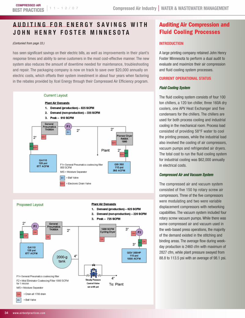
| 1 1 – 1 2 / 0 7 Compressed Air Industry | WATer & WAsTeWATer mAnAgemenT
34 www.ai rbestpract ices .com
A U D I T I n g F O r e n e r g Y s A v I n g s W I T H J O H n H e n r Y F O s T e r m I n n e s O T A
has seen significant savings on their electric bills, as well as improvements in their plant’s response times and ability to serve customers in the most cost-effective manner. The new system also reduces the amount of downtime needed for maintenance, troubleshooting and repair. The packaging company is now on track to save over $20,000 annually on electric costs, which offsets their system investment in about four years when factoring in the rebates provided by Xcel Energy through their Compressed Air Efficiency program.
InTrODUCTIOn
A large printing company retained John Henry Foster Minnesota to perform a dual audit to evaluate and maximize their air compression and fluid cooling system processes.
CUrrenT OPerATIOnAl sTATUs
Fluid Cooling System
The fluid cooling system consists of four 100 ton chillers, a 120 ton chiller, three 160A dry coolers, one APV Heat Exchanger and five condensers for the chillers. The chillers are used for both process cooling and industrial cooling in the mechanical room. Process load consisted of providing 58°F water to cool the printing presses, while the industrial load also involved the cooling of air compressors, vacuum pumps and refrigerated air dryers. The total cost to run the fluid cooling system for industrial cooling was $62,000 annually in electrical costs.
Compressed Air and Vacuum System
The compressed air and vacuum system consisted of five 150 hp rotary screw air compressors. Three of the five compressors were modulating and two were variable displacement compressors with networking capabilities. The vacuum system included four rotary screw vacuum pumps. While there was some compressed air and vacuum used in the web-based press operations, the majority of the demand existed in the stitching and binding areas. The average flow during week-day production is 2460 cfm with maximum of 2827 cfm, while plant pressure swayed from 88.8 to 113.5 psi with an average of 98.1 psi.
Auditing Air Compression and Fluid Cooling Processes
(Contunied from page 33.)
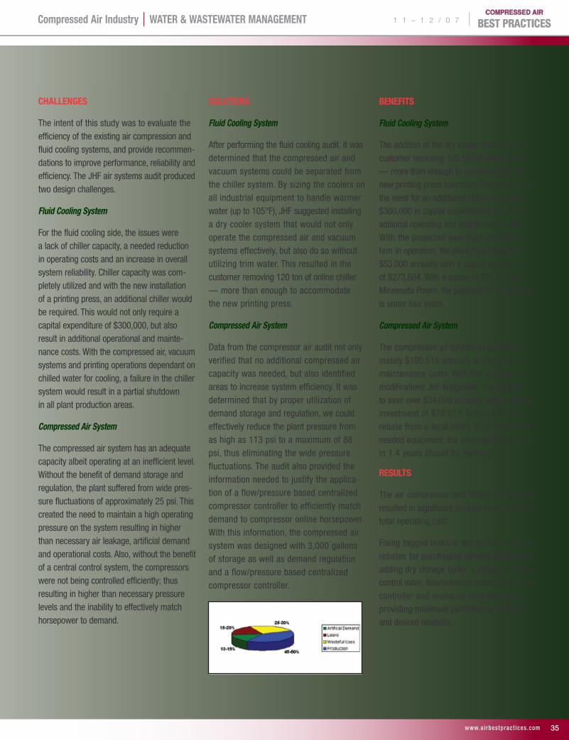
1 1 – 1 2 / 0 7 |Compressed Air Industry | WATer & WAsTeWATer mAnAgemenT
www.ai rbestpract ices .com 35
CHAllenges
The intent of this study was to evaluate the efficiency of the existing air compression and fluid cooling systems, and provide recommen-dations to improve performance, reliability and efficiency. The JHF air systems audit produced two design challenges.
Fluid Cooling System
For the fluid cooling side, the issues were a lack of chiller capacity, a needed reduction in operating costs and an increase in overall system reliability. Chiller capacity was com-pletely utilized and with the new installation of a printing press, an additional chiller would be required. This would not only require a capital expenditure of $300,000, but also result in additional operational and mainte-nance costs. With the compressed air, vacuum systems and printing operations dependant on chilled water for cooling, a failure in the chiller system would result in a partial shutdown in all plant production areas.
Compressed Air System
The compressed air system has an adequate capacity albeit operating at an inefficient level. Without the benefit of demand storage and regulation, the plant suffered from wide pres-sure fluctuations of approximately 25 psi. This created the need to maintain a high operating pressure on the system resulting in higher than necessary air leakage, artificial demand and operational costs. Also, without the benefit of a central control system, the compressors were not being controlled efficiently; thus resulting in higher than necessary pressure levels and the inability to effectively match horsepower to demand.
sOlUTIOns
Fluid Cooling System
After performing the fluid cooling audit, it was determined that the compressed air and vacuum systems could be separated from the chiller system. By sizing the coolers on all industrial equipment to handle warmer water (up to 105°F), JHF suggested installing a dry cooler system that would not only operate the compressed air and vacuum systems effectively, but also do so without utilizing trim water. This resulted in the customer removing 120 ton of online chiller — more than enough to accommodate the new printing press.
Compressed Air System
Data from the compressor air audit not only verified that no additional compressed air capacity was needed, but also identified areas to increase system efficiency. It was determined that by proper utilization of demand storage and regulation, we could effectively reduce the plant pressure from as high as 113 psi to a maximum of 88 psi, thus eliminating the wide pressure fluctuations. The audit also provided the information needed to justify the applica-tion of a flow/pressure based centralized compressor controller to efficiently match demand to compressor online horsepower. With this information, the compressed air system was designed with 3,000 gallons of storage as well as demand regulation and a flow/pressure based centralized compressor controller.
BeneFITs
Fluid Cooling System
The addition of the dry cooler resulted in the customer removing 120 ton of online chiller — more than enough to accommodate the new printing press operation. This eliminated the need for an additional chiller and saved $300,000 in capital expenditures as well as addional operating and maintenance costs. With the projected new fluid cooling sys-tem in operation, the plant could save over $53,000 annually with a capital investment of $273,604. With a rebate of $75,628 from Minnesota Power, the payback for the project is under four years.
Compressed Air System
The compressed air system costs approxi-mately $190,515 annually in electrical and maintenance costs. With the appropriate modifications JHF suggested, it is expected to save over $34,000 annually with a capital investment of $78,977. With a $29,556 rebate from a local utility to purchase the needed equipment, the return on investment in 1.4 years should be realized.
resUlTs
The air compressor and fluid cooling audit resulted in significant savings to the facility’s total operating cost.
Fixing tagged leaks in the system, utilizing rebates for purchasing needed equipment, adding dry storage tanks, a steady pressure control valve, flow/pressure based compressor controller and drains all contributed to providing maximum performance efficiency and desired reliability.
| 1 1 – 1 2 / 0 7 Compressed Air Industry | WATer & WAsTeWATer mAnAgemenT
36 www.ai rbestpract ices .com
Pros and Cons of Selling Pneumatics and Compressed Air Systems
John Henry Foster Minnesota provides an infrastructure to support its sales professionals, who are educated, trained and focused in both arenas. We also have a technical support system consisting of teams of specialists in pneumatic component and capital equipment applica-tions. These professionals range from master electricians, mechanical engineers, electrical engineers, service coordinators, mechanics and piping experts. JHF has a significant advantage over companies that have one-sided representatives, as this infrastructure allows the flex-ibility to present and address the complete system from design through implementation, thus being involved with the entire client organization including; machine design, engineering, planning, production and plant management. Clients need their systems to function properly and reliability is vital to their production floors. Due to downsizing, clients do not always have the expertise to handle the systems. Their jobs usually depend upon the systems running continuously. Downtime results in lost revenue, quality control issues, product recalls and diminished speed to market. Our strategic process brings additional value to the client by limiting their need to outsource costly expertise to administer the entire system.
One drawback to the structure of providing consultative sales in a full-service environment is that it forces our sales professionals to be knowledgeable and educated in both applications and products. We compete with one-sided representatives, which increases demand on our product knowledge. For a sales professional to become self-sufficient and profitable, it takes five to seven years of training and experience.
Clients that purchase air compressors for the supply side of the business typically have long periods of time before an upgrade or repurchase. Since we are a full-service organization and pneumatic components are a consumable product, our sales professionals have the ability to utilize that time to work with the clients to fulfill their pneumatics and fluid power needs. This allows for continued contact and relationship building with the client; therefore we are then aware of the client’s growth and expansion plans. John Henry Foster Minnesota is based on creating partnerships with clients and as their business needs change, we align to bring new solutions.
Market’s Served
John Henry Foster Minnesota is involved with virtually every industry since motion control technology and power generation is used in some form in industrial applications. The typical company JHF services ranges from smaller mid-sized industries to Fortune 500 companies. The industry type is very diverse, such as agricultural and meat processing plants, to large industrial manufacturers, such as hospitals and printing facilities.
Conclusion
For more than 70 years, John Henry Foster Minnesota has been the Midwest’s leading air compressor systems distributor and service provider. The JHF teams of air automation experts bring customized client solutions in consistency, reliability and profitability. We demon-strate the latest trends in world-class compressed air automation, air compressors, pneumatic components and electrical controls, plus 80/20 aluminum framing systems.
For more information contact: Ron Nordby, Vice President, John Henry Foster Minnesota, tel: 651.681.5724, email: [email protected], www.jhfostermn.com
A U D I T I n g F O r e n e r g Y s A v I n g s W I T H J O H n H e n r Y F O s T e r m I n n e s O T A
2008 FOCUs InDUsTrIes!Energy Management, Bulk Handling, Food
Processing, Plastics & Blow-Molding
IDeAl FOr:Industry:
Plant Engineers, Plant Managers & Maintenance Managers
Compressor dIstrIbutors: Every Branch Location
manufaCturers: Management, Sales, Marketing
& Engineering
FOr FAsTesT servICe: Fax: 412-831-3091
Email: [email protected]: www.airbestpractices.com
Name:
Title:
Company:
Street:
City: State: Zip Code:
Email:
Please sign here if you wish to receive/continue to receive Compressed Air Best Practices free*
Signature Required Date
* $65 in Canada and $95 for other countries.
O c t o b e r 2 0 0 7
ArcelorMittal Savings Air Dryers Compressor Controls
2 0 0 8 F r e e U . s . s U B s C r I P T I O n
(Contunied from page 32.)
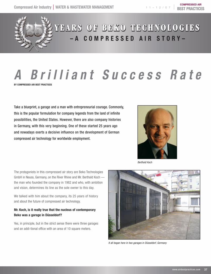
1 1 – 1 2 / 0 7 |Compressed Air Industry | WATer & WAsTeWATer mAnAgemenT
37 www.ai rbestpract ices .com
A B r i l l i a n t S u c c e s s R a t e BY COmPresseD AIr BesT PrACTICes
The protagonists in this compressed air story are Beko Technologies
GmbH in Neuss, Germany, on the River Rhine and Mr. Berthold Koch —
the man who founded the company in 1982 and who, with ambition
and vision, determines its line as the sole owner to this day.
We talked with him about the company, its 25 years of history
and about the future of compressed air technology.
mr. Koch, is it really true that the nucleus of contemporary
Beko was a garage in Düsseldorf?
Yes, in principle, but in the strict sense there were three garages
and an addi-tional office with an area of 10 square meters.
Berthold Koch
It all began here in two garages in Düsseldorf, Germany
y e a r s o f b e k o t e C h n o l o g I e s– A C O m P r e s s e D A I r s T O r Y –
Take a blueprint, a garage and a man with entrepreneurial courage. Commonly,
this is the popular formulation for company legends from the land of infinite
possibilities, the United States. However, there are also company histories
in Germany, with this very beginning. One of these started 25 years ago
and nowadays exerts a decisive influence on the development of German
compressed air technology for worldwide employment.
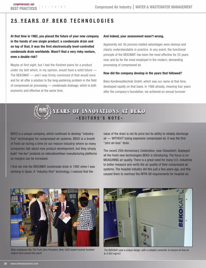
| 1 1 – 1 2 / 0 7 Compressed Air Industry | WATer & WAsTeWATer mAnAgemenT
At that time in 1982, you placed the future of your new company
in the hands of one single product: a condensate drain and
on top of that, it was the first electronically level-controlled
condensate drain worldwide. Wasn't that a very risky venture,
even a double risk?
Maybe at first sight, but I had the finished plans for a product
under my belt which, in my opinion, would have a solid future —
The BEKOMAT — and I was firmly convinced of that would once
and for all offer a solution to the long-pestering problem in the field
of compressed air processing — condensate drainage, which is both
economic and effective at the same time.
And indeed, your assessment wasn't wrong.
Apparently not. Its process-related advantages were obvious and
clearly understandable in practice. In any event, the functional
principle of the BEKOMAT has been the most effective for 25 years
now, and by far the most employed in the modern, demanding
processing of compressed air.
How did the company develop in the years that followed?
Beko Kondensattechnik GmbH, which was our name at that time,
developed rapidly on that basis. In 1986 already, meaning four years
after the company's foundation, we achieved an annual turnover
2 5 Y e A r s O F B e K O T e C H n O l O g I e s
BEKO is a unique company, which continues to develop “industry-
first” technologies for compressed air systems. BEKO is a breath
of fresh air during a time (in our mature industry) where so many
companies talk about new product development, but they simply
build “me-too” products on rationalized/lean manufacturing platforms
so margins can be increased.
I first ran into the BEKOMAT condensate drain in 1992 when I was
working in Spain. A “industry-first” technology, I realized that the
value of the drain is not its price but its ability to reliably discharge air — WITHOUT losing expensive compressed air. It was the first “zero air-loss” drain.
The recent 25th Anniversary Celebration, near Düsseldorf, displayed all the fresh new technologies BEKO is introducing. The focus is on MEASURING air quality. There is a great need for many U.S. industries to better measure and verify the air quality of their compressed air systems. The hospital industry did this just a few years ago, and this caused them to overhaul the NFPA 99 requirements for hospital air.
The BEKOKAT uses a unique design, with a catalytic converter, to ensure oil-free air to 0.003 mg/m3
38 www.ai rbestpract ices .com
y e a r s o f I n n o vat I o n s at b e k o– e D I T O r s ’ s n O T e –
Beko employees like Tilo Fruth (Vice President, Beko USA) hosted several hundred visitors from around the world
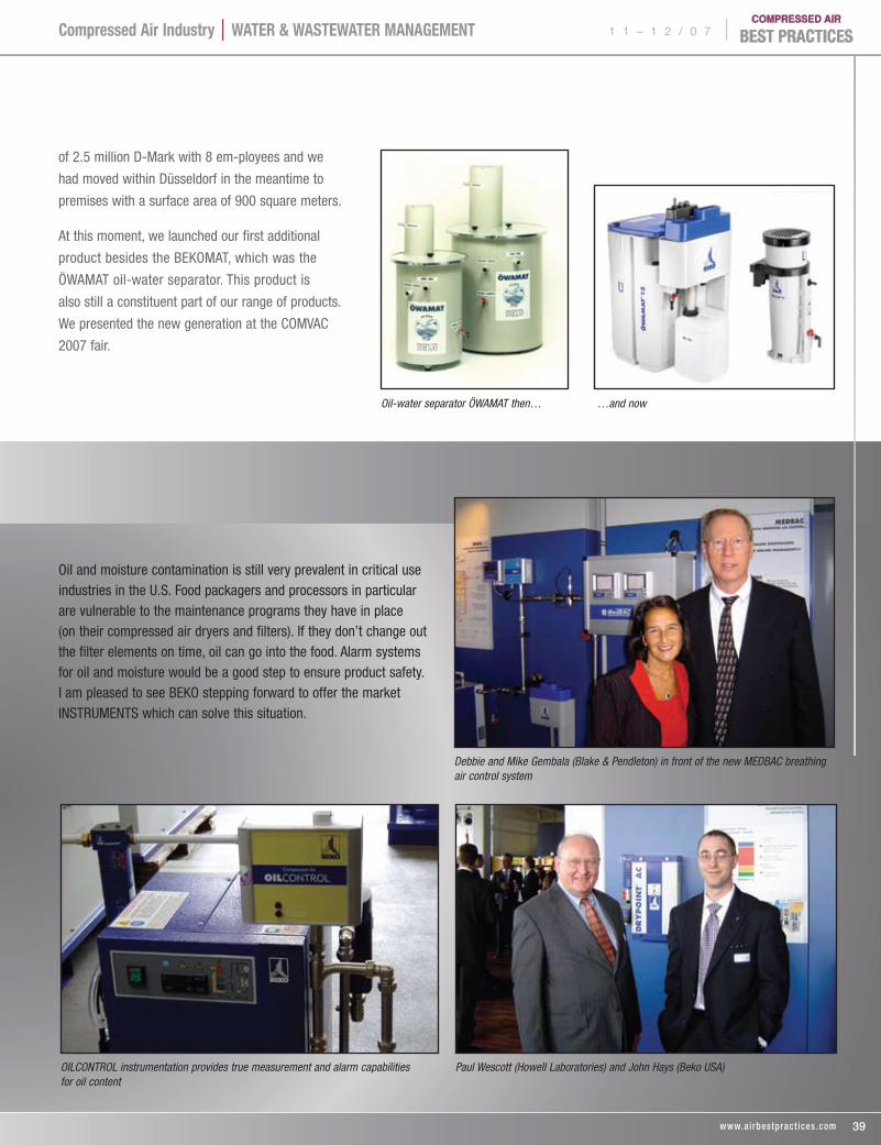
1 1 – 1 2 / 0 7 |Compressed Air Industry | WATer & WAsTeWATer mAnAgemenT
Paul Wescott (Howell Laboratories) and John Hays (Beko USA)
Oil and moisture contamination is still very prevalent in critical use industries in the U.S. Food packagers and processors in particular are vulnerable to the maintenance programs they have in place (on their compressed air dryers and filters). If they don’t change out the filter elements on time, oil can go into the food. Alarm systems for oil and moisture would be a good step to ensure product safety. I am pleased to see BEKO stepping forward to offer the market INSTRUMENTS which can solve this situation.
OILCONTROL instrumentation provides true measurement and alarm capabilities for oil content
of 2.5 million D-Mark with 8 em-ployees and we
had moved within Düsseldorf in the meantime to
premises with a surface area of 900 square meters.
At this moment, we launched our first additional
product besides the BEKOMAT, which was the
ÖWAMAT oil-water separator. This product is
also still a constituent part of our range of products.
We presented the new generation at the COMVAC
2007 fair.
39 www.ai rbestpract ices .com
Debbie and Mike Gembala (Blake & Pendleton) in front of the new MEDBAC breathing air control system
Oil-water separator ÖWAMAT then… …and now
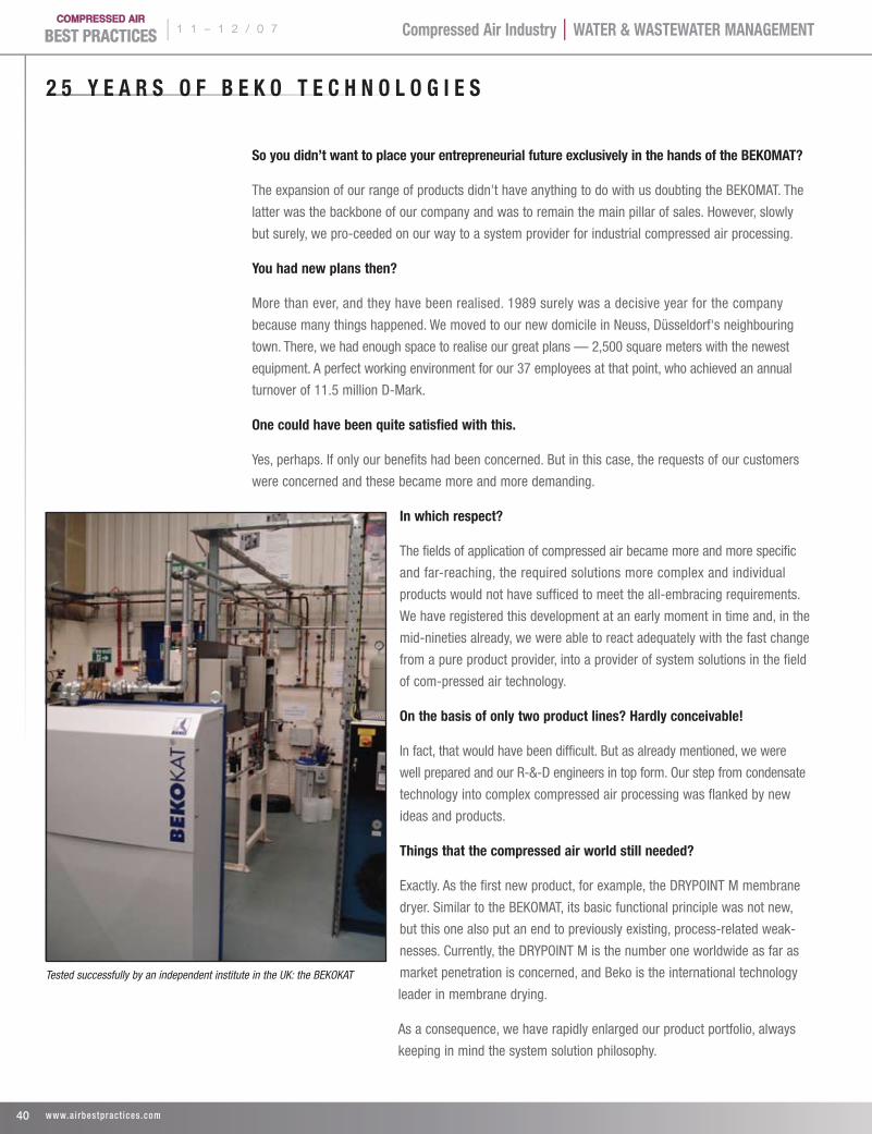
| 1 1 – 1 2 / 0 7 Compressed Air Industry | WATer & WAsTeWATer mAnAgemenT
2 5 Y e A r s O F B e K O T e C H n O l O g I e s
so you didn’t want to place your entrepreneurial future exclusively in the hands of the BeKOmAT?
The expansion of our range of products didn't have anything to do with us doubting the BEKOMAT. The
latter was the backbone of our company and was to remain the main pillar of sales. However, slowly
but surely, we pro-ceeded on our way to a system provider for industrial compressed air processing.
You had new plans then?
More than ever, and they have been realised. 1989 surely was a decisive year for the company
because many things happened. We moved to our new domicile in Neuss, Düsseldorf's neighbouring
town. There, we had enough space to realise our great plans — 2,500 square meters with the newest
equipment. A perfect working environment for our 37 employees at that point, who achieved an annual
turnover of 11.5 million D-Mark.
One could have been quite satisfied with this.
Yes, perhaps. If only our benefits had been concerned. But in this case, the requests of our customers
were concerned and these became more and more demanding.
In which respect?
The fields of application of compressed air became more and more specific
and far-reaching, the required solutions more complex and individual
products would not have sufficed to meet the all-embracing requirements.
We have registered this development at an early moment in time and, in the
mid-nineties already, we were able to react adequately with the fast change
from a pure product provider, into a provider of system solutions in the field
of com-pressed air technology.
On the basis of only two product lines? Hardly conceivable!
In fact, that would have been difficult. But as already mentioned, we were
well prepared and our R-&-D engineers in top form. Our step from condensate
technology into complex compressed air processing was flanked by new
ideas and products.
Things that the compressed air world still needed?
Exactly. As the first new product, for example, the DRYPOINT M membrane
dryer. Similar to the BEKOMAT, its basic functional principle was not new,
but this one also put an end to previously existing, process-related weak-
nesses. Currently, the DRYPOINT M is the number one worldwide as far as
market penetration is concerned, and Beko is the international technology
leader in membrane drying.
As a consequence, we have rapidly enlarged our product portfolio, always
keeping in mind the system solution philosophy.
Tested successfully by an independent institute in the UK: the BEKOKAT
40 www.ai rbestpract ices .com
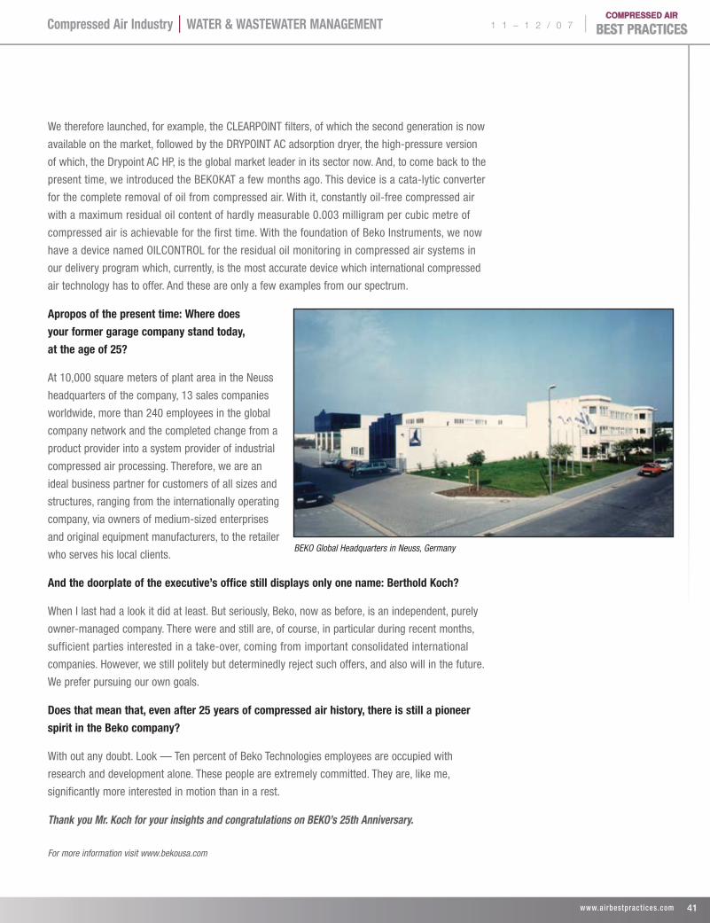
1 1 – 1 2 / 0 7 |Compressed Air Industry | WATer & WAsTeWATer mAnAgemenT
41 www.ai rbestpract ices .com
We therefore launched, for example, the CLEARPOINT filters, of which the second generation is now
available on the market, followed by the DRYPOINT AC adsorption dryer, the high-pressure version
of which, the Drypoint AC HP, is the global market leader in its sector now. And, to come back to the
present time, we introduced the BEKOKAT a few months ago. This device is a cata-lytic converter
for the complete removal of oil from compressed air. With it, constantly oil-free compressed air
with a maximum residual oil content of hardly measurable 0.003 milligram per cubic metre of
compressed air is achievable for the first time. With the foundation of Beko Instruments, we now
have a device named OILCONTROL for the residual oil monitoring in compressed air systems in
our delivery program which, currently, is the most accurate device which international compressed
air technology has to offer. And these are only a few examples from our spectrum.
Apropos of the present time: Where does
your former garage company stand today,
at the age of 25?
At 10,000 square meters of plant area in the Neuss
headquarters of the company, 13 sales companies
worldwide, more than 240 employees in the global
company network and the completed change from a
product provider into a system provider of industrial
compressed air processing. Therefore, we are an
ideal business partner for customers of all sizes and
structures, ranging from the internationally operating
company, via owners of medium-sized enterprises
and original equipment manufacturers, to the retailer
who serves his local clients.
And the doorplate of the executive’s office still displays only one name: Berthold Koch?
When I last had a look it did at least. But seriously, Beko, now as before, is an independent, purely
owner-managed company. There were and still are, of course, in particular during recent months,
sufficient parties interested in a take-over, coming from important consolidated international
companies. However, we still politely but determinedly reject such offers, and also will in the future.
We prefer pursuing our own goals.
Does that mean that, even after 25 years of compressed air history, there is still a pioneer
spirit in the Beko company?
With out any doubt. Look — Ten percent of Beko Technologies employees are occupied with
research and development alone. These people are extremely committed. They are, like me,
significantly more interested in motion than in a rest.
Thank you Mr. Koch for your insights and congratulations on BEKO’s 25th Anniversary.
For more information visit www.bekousa.com
BEKO Global Headquarters in Neuss, Germany
| 1 1 – 1 2 / 0 7
42 www.ai rbestpract ices .com
Compressed Air Industry | WATer & WAsTeWATer mAnAgemenT
@The Good, the Bad, the Ugly:BY rOnnIe mOOre
Before thinking about how to compose a good e-mail, it’s critical to think about whether e-mail is the right vehicle for the communication in the first place. E-mail has become such an integral part of our lives that many of us check it as soon as we get up in the morning, before we reach our destination in the airplane, before we go to bed at night. But the “e” in e-mail means “electronic,” NOT “everything.” So consider the following before going on “e-mail autopilot.”
E-mail is an effective communications vehicle when:
p Simply downloading and uploading information. E-mail is the cheapest and fastest way to send and receive information, including information, pictures, etc. via attachments. We are no longer dependent on fax machines, couriers and the U.S. mail for the simple exchange of information. This is e-mail at its finest.
p You need to reach many people at the same time, often at different locations. We work in a telecommute, business travel, global professional world. E-mail, instant messaging, etc. allows us to be in constant and immediate contact with our colleagues, no matter where we are geographically.
p The message does not require repeated interaction. E-mail’s intended expedience and efficiency is compromised when the communication requires discussion. Here’s what the “e” trail (e-mail’s version of a paper trail) looked like on a communication between Veronica and Susan:
E-mail #1 (from Susan to Veronica)
Veronica,What do you think of the ABC Company as a provider of the computer-training we need?
E-mail #2 (from Veronica to Susan)
Susan,I don’t know much about them. What other like companies have they helped with this type of training?
E-mail #3 (from Susan to Veronica)
I don’t know. I’ll find out. Do you know anything about their curriculum or trainers?
E-mail #4 (from Veronica to Susan)
I know a little bit about their approach to adult learning, and I don’t know anything about their trainers. And that’s critical because the trainer will make or break even the best curriculum, especially in a subject like this, where it’s technical, hands-on and potentially tedious if not presented well.
And so on…
Ronnie Moore
1 1 – 1 2 / 0 7 |
43 www.ai rbestpract ices .com
Compressed Air Industry | WATer & WAsTeWATer mAnAgemenT
@The Good, the Bad, the Ugly: e - m A I l C O m m U n I C A T I O n
It took Susan and Veronica eight e-mail messages to conclude this communication. Had they spent five minutes talking in person or by telephone, they would have been far more expedient and efficient.
E-mail is not effective when:
It is replacing face-to-face communication
And here lies the human disconnect. We need to see each other’s eyes. We need nonverbal communication. We need to hear someone’s voice (even if it’s on the phone).
Bob was promoted to management because of his technical skills and knowledge (he’s a brilliant engineer), and strong work ethic. The problem, however, is that he was promoted for his ability to perform and manage functions, not people. Bob never learned how to manage and communicate with others.
Bob was concerned that he was not connecting with his staff — that he was “out of the loop.” He felt he was in constant contact with his employees, but sending “Bob-O-Grams” from his computer all day does not translate to Bob communicating effectively. His employees were all within 50 feet of him, yet he chose to “communicate” with them by e-mail.
Conflict needs to be resolved
We often say things via e-mail we would not say if we were not safely behind the screen. There are several reasons that communicating through conflict should occur in person, or at the very least by telephone, but never via e-mail.
Face-to-face communication is a three “channel” experience. We send our message with our words (verbal channel), our voice (vocal channel) and our face and body (nonverbal channel). The same words communicated with a pleased voice versus an angry voice will be received differently. We know that a smile versus an angry face changes the meaning of our words. The problem is that we need all three channels. We need to use our words, our voice and our face and body congruently to ensure that our intended message is received. When we use the telephone, we lose the third channel (the nonverbal channel) and now we are dependent on our words and voice only. Our listener can’t see our face and body to get a more rounded idea of what we really mean. In fact, one of the first
things that telephone skills training teaches is that if you provide customer service via telephone, you must get in the habit of smiling as you answer the phone. Your listener/customer can’t SEE your smile, so your listener must HEAR your smile.
The problem worsens when you try to resolve conflict by communi-cating via e-mail. Now you’re down to only one channel: your words. Without a voice or a face or body language, you have huge potential for misunderstanding, because the person with whom you share the conflict, the person to whom you’re sending your e-mail, cannot hear you or see you and must judge your true meaning and intent by your words only.
Communicating private/proprietary information
The term “private e-mail” is usually an oxymoron, especially in the workplace. Read your employer’s e-mail guidelines. Chances are your employer can read your e-mails at any time. Chances are you can be held responsible for what you originate or what you forward, and you are not held responsible for unsolicited messages you receive. So think twice about that hilarious joke you’re dying to send or forward to others. Is it appropriate in the work place? Make sure that no message you originate or forward could be used against you in matters of discipline, termination, etc. Anything racist, sexist or sexual should not originate from your e-mail account and should stop with you. Save the questionable stuff, the personal stuff for your personal e-mail account.
Well-formatted, clear, concise e-mail messages are critical to getting our messages read and getting the responses we need. But before you think about what you’re going to communicate in that e-mail, make sure e-mail is the best way to go.
Copyright 2007 Ronnie Moore Excerpted/recreated from “Why Did I Say That? Communicating to keep your credibility, your cool, and your cash!” by Ronnie Moore
ABOUT THE AUTHORRonnie Moore, a highly sought-after speaker and trainer, is the author of “Why Did I Say That? Communicating to Keep Your Credibility, Your Cool and Your Cash!” and “Tricks that Stick,” a writing companion. A nationally known expert on spoken and written communication, she has worked with IHOP, Hyundai, the US Department of Commerce, the EPA, government agencies and major universities. Her books and speaking information are available on her website www.rmoorecommunications.com or call 909-229-4755, email [email protected].
44 www.ai rbestpract ices .com
Compressed Air Industry | WATer & WAsTeWATer mAnAgemenT | 1 1 – 1 2 / 0 7
Wa l l S t r e e t Wa t c h
BY COmPresseD AIr BesT PrACTICes
Hamilton, Bermuda, september 4, 2007 — Ingersoll-rand Company limited (nYse:Ir) announced that it has signed an agreement to purchase the privately owned Officine Meccaniche Industriali srl (OMI), a leading European provider of compressed-air treatment equipment. Terms of the transaction were not disclosed.
OMI develops and manufactures a complete line of compressed-air treatment products, including air dryers, filters, chillers and system controllers, that maximize the productivity and reliability of compressed-air systems for a variety of industrial and manufacturing applications. Founded in 1989, OMI is based in northeast Italy in Fogliano Redipuglia, Gorizia Province, and has an additional facility in Logatec, Slovenia.
“The acquisition of OMI reflects our intention to build upon one of our core business platforms relating to industrial productivity,” said Herbert L. Henkel, chairman, president and chief executive officer for Ingersoll Rand. “With its strong distribution channels throughout Europe, Asia and Latin America, OMI advances our leadership as a global provider of innovative and comprehensive compressed-air systems and extends our line of Ingersoll Rand compressed air products and services.”
Upon completion of the acquisition, which is scheduled for late September 2007, OMI will operate as part of the Air Solutions business of Ingersoll Rand’s Industrial Technologies Sector.
DAnA POInT, Calif., september 11, 2007 — United Technologies Corp. (nYse:UTX) Chairman and Chief Executive Officer George David today announced increased expectations for share repurchase during 2007. During comments made at the Morgan Stanley CEOs Unplugged Industrials Conference, David raised guidance for 2007 share repurchase to $2 billion, up from the prior $1.5 billion expec-tation, and confirmed the outlook for 2007 acquisitions spending in the range of $2 billion for the year, unchanged from prior projections. David also reaffirmed the company’s 2007 outlook for earnings per share and cash flow. EPS is anticipated to be in the range of $4.15 to $4.25 and cash flow from operations after capital expenditures to exceed net income for the year.
rock Hill, s.C., August 30, 2007 — Atlas Copco. Rotary screw air compressors manufactured by Atlas Copco Compressors LLC are among the first in the world whose performance ratings have been verified in independent testing sponsored by the Compressed Air and Gas Institute, a group representing industry manufacturers. The testing was conducted by Intertek Testing Services, administrator of the CAGI Performance Verification Program.
The intent of this column is to provide industry watchers with publicly held information on publicly held companies involved with the sub-industry of compressed air. It is not the intent of the column to provide any opinions or recommendations related to stock valuations. All information in this column was gathered on October 11, 2007.
1 1 – 1 2 / 0 7 |
45 www.ai rbestpract ices .com
Atlas Copco is the world’s leading manufacturer of compressed air equipment and has been a pioneer in introducing new air compressor technologies, including oil-free and variable speed drive systems. The company has been at the forefront in improving industry standards for air compressor performance and in reducing the environmental impact and energy usage of equipment. CAGI introduced its Performance Verification Program to ensure that purchasers are provided with accurate product information. Participation in the testing program is voluntary and open to all manufacturers, whether or not they are members of CAGI. Test results are published on the organization’s web site (www.cagi.org). The CAGI program verifies the information that manufacturers publish on CAGI data sheets, including air flow capacities and efficiencies. Multiple units are tested annually at random to verify that equipment performance is consistent with published information. Potential customers use CAGI data sheets to review operational and performance information for product consideration and comparison. Manufacturers whose products pass the testing process are able to use the CAGI Performance Verification Program Seal on specification sheets and on their products and literature. “We are very pleased to participate in this program, which underscores our commitment to providing purchasers with accurate, unbiased information on product performance,” said David Prator, Southern Regional Vice President of Atlas Copco Compressors LLC. “Equipment quality, efficiency and reliability are critical to customers, and the CAGI Performance Verification Program will help them select air compressor systems that best meet their performance requirements.”
stockholm, sweden, september 24, 2007 — Atlas Copco
Atlas Copco has been selected to be a new member of the Dow Jones Sustainability Indexes, which track the financial performance of the world’s leading companies in terms of sustainability.
As of September 24, Atlas Copco will be included in the Dow Jones Sustainability World Index (DJSI World), and in the European Dow Jones STOXX Sustainability Index (DJSI STOXX). The indexes provide asset managers with benchmarks to manage portfolios based on criteria for corporate sustainability, such as efforts by companies to manage their impact on society and the environment.
“We are pleased with this recognition of our work to manage Atlas Copco’s business in a sustainable manner,” says Annika Berglund, Senior Vice President, Atlas Copco Corporate Communications. “This is a continuous effort of which all of our co-workers around the world are part.”
Atlas Copco continuously works to reduce the impact on the environ-ment from its production processes and monitors key performance indicators, such as use of energy, water and transport fuel and carbon dioxide emissions. In relation to cost of sales, energy use was reduced by 11% in 2006, while carbon dioxide emissions decreased 5%.
DJSI World comprises more than 300 companies that represent the top 10% sustainability companies of the biggest companies in the Dow Jones World Index. DJSI STOXX tracks the top 20% of Europe’s 600 largest companies, as measured by the Dow Jones STOXX 600 Index. Both indexes are reviewed annually.
CHArlOTTe, n.C., Aug. 3 — enPro Industries (nYse: nPO) reported its segment profits grew by 22% in the second quarter of 2007 as sales increased by 12% and segment profit margins reached 17.3%. Sales, segment profits and segment profit margins all reached new highs, exceeding the record levels achieved in the first quarter of 2007.
“We are pleased to report another truly outstanding quarter,” said Ernie Schaub, president and chief executive officer. “Our operations performed well, our markets remained favorable and we continued to effectively execute our management strategies, all of which contributed to our results in the quarter and to the pattern of consistent improvement we have established in our five years as an independent company.”
Net income in the second quarter of 2007 was $13.8 million, or $0.61 a share, compared to net income of $4.2 million, or $0.19 a share, in the second quarter of 2006. Net income in both periods was reduced by asbestos-related expenses, which amounted to $13.1 million, before tax, in the second quarter of 2007 and $20.7 million, before tax, in the second quarter of 2006. Before asbestos-related expenses and other selected items, income in the second quarter of 2007 improved to $22.8 million, or $1.01 a share, compared to the second quarter of 2006, when income was $17.2 million, or $0.79 a share.
Sales in the second quarter of 2007 increased to $254.4 million, compared to $226.7 million in the second quarter of 2006, as each of the company’s segments reported sales growth. The Sealing Products and Engineered Products segments benefited from higher levels of activity in their industrial markets, acquisitions and foreign exchange, while the Engine Products and Services segment benefited from increased engine shipments.
Compressed Air Industry | WATer & WAsTeWATer mAnAgemenT
| 1 1 – 1 2 / 0 7
46 www.ai rbestpract ices .com
Compressed Air Industry | WATer & WAsTeWATer mAnAgemenT
Segment profits grew to $43.9 million, a 22% improvement over the second quarter of 2006, when they were $36.0 million, and segment margins reached 17.3% compared to 15.9% a year ago. Improved pricing, increased volumes, lower pension expense, acquisitions and foreign exchange each benefited segment profits in the second quarter.
For the first six months of 2007, EnPro’s net income was $26.1 million, or $1.17 a share, compared to $19.0 million, or $0.88 a share in the first six months of 2006. Asbestos-related expenses reduced net income by $26.0 million, before tax, in the first half of 2007 compared to $25.6 million, before tax, in the first half of last year. Before asbestos-related expenses and other selected items, income in the first half of 2007 was $43.8 million, or $1.97 a share, a 20% improvement in earnings per share over the first half of 2006, when income before asbestos-related expenses and other selected items was $35.3 million, or $1.64 a share.
Sales in the first half of 2007 were $501.7 million compared to $455.0 million in the first half of 2006. The 10% increase was the result of higher levels of activity at all of the company’s segments as well as the benefit of acquisitions and foreign exchange, which were responsible for about 5 percentage points of the sales increase.
Segment profits grew to $86.1 million in the first half of 2007, a 16% improvement over the first half of 2006, when segment profits were $74.3 million. Segment margins improved to 17.2% in the first half of the year from 16.3% a year ago. Profits in the first half of 2007 benefited from volume increases, pricing, acquisitions and lower pension expense.
Sales in the Engineered Products segment increased 8% in the second quarter of 2007 over the second quarter of 2006. Increased demand from European markets led to solid growth in sales at GGB Bearing Technology despite a modest decline in sales to North American industrial and automotive markets. At France Compressor Products (FCP), sales increased reflecting substantial improvements in North American and European compressor markets and acquisitions made in 2006. However, sales at Quincy Compressor declined modestly from the record levels of a year ago as North American industrial and energy markets softened and demand for new compressors decreased. About 6 percentage points of the increase in the segment’s sales came from favorable foreign exchange rates and acquisitions. The segment’s profits grew by 12% compared to the second quarter of 2006. Profit margins increased to 17.0%. GGB benefited from improvements in its European markets, greater efficiencies, better pricing and a stronger euro. FCP also benefited from increased volumes as well as from contributions from acquisitions completed in 2006. At Quincy Compressor, however, profits declined, primarily due to lower volumes.
mInneAPOlIs, mn (sept. 4, 2007) — Donaldson Company, Inc. (nYse: DCI) announced fourth quarter diluted earnings per share (“EPS”) of $.53, up 23% from $.43 last year. Net income was $43.3 million, versus $36.2 million last year. Sales were $524.7 million, up from $468.2 million in fiscal 2006.
For the year, EPS was $1.83, up 18% from $1.55 last year. Net income increased 14% to $150.7 million compared to $132.3 million last year. Sales were $1.919 billion, up 13% from $1.694 billion in fiscal 2006.
W A l l s T r e e T W A T C H

1 1 – 1 2 / 0 7 |
47 www.ai rbestpract ices .com
Compressed Air Industry | WATer & WAsTeWATer mAnAgemenT
“We are very pleased to announce that we achieved our 18th con-secutive year of record earnings with an EPS increase of 18 percent for the year,” said Bill Cook, Chairman, President and CEO. “We made great progress on the operating issues that impacted our results earlier in the year, delivering a 12.3% operating margin in the quarter, and bringing our operating margin back to our 11% target for the full year.”
Key factors contributing to the quarter’s results included:
Strong Engine Products sales
p International sales increased dramatically, with over 20% increases in our European off-road and aftermarket businesses. Our Asian off-road and aftermarket businesses posted sales increases of 23 and 15% respectively.
p NAFTA truck sales decreased a less-than-expected $14 million in the fourth quarter following the implementation of the new EPA diesel emission standards earlier this year. 17% sales increase for Industrial Products
p Industrial Filtration Solutions delivered an 18% sales increase due to very strong results in Europe and Asia.
p Special Applications sales were up 19% on strong disk drive filter and PTFE membrane sales. Operating margin improvement
p We saw improvement in our global distribution efficiencies, while continuing our investments in new systems and process enhance-ments for the future. “Our sales trends remain positive as we enter fiscal 2008,” said Bill Cook. “We expect to continue to make progress on our operating initiatives throughout the year, which should provide additional operating leverage. As a result, we are expecting to deliver another earnings record in fiscal 2008.”
Fiscal 2008 Outlook
engine Products: We expect 5 to 7% full year sales growth.
p Due to the continued impact of the EPA diesel emission standards, we expect our NAFTA Transportation Products sales to decrease $30 to $40 million in our first three quarters before growth returns in our fourth quarter.
p Production of new heavy construction and mining equipment by our international OEM Customers is forecasted to remain healthy. We expect NAFTA non-residential and public construction markets to benefit from continued infrastructure investment. Production of new agriculture equipment by our Customers is expected to remain strong globally.
p Our Aftermarket sales are expected to continue growing due to strong equipment utilization in the field and the increasing amount of equipment with our PowerCore™ filtration systems.
Industrial Products: We expect 8 to 10% full year sales growth.
p Our Industrial Filtration sales are projected to grow 10% due to continued strong global manufacturing investment and production utilization conditions.
p We expect high-single digit percent sales growth in Gas Turbine Products over last year's 30% growth. Continued strength is expect-ed from both the international power generation and the oil and gas market segments.
OCTOBer 11, 2007PrICe PerFOrmAnCe sYmBOl lAsT
PrICe1
mOnTH6
mOnTHs12
mOnTHs
Parker-Hannifin PH $76.25 8.4% 28.8% 40.3%
Ingersoll Rand IR $53.48 6.0% 21.8% 34.2%
Gardner Denver GDI $39.91 8.4% 10.5% 20.7%
United Technologies UTX $79.21 8.1% 24.9% 23.3%
Donaldson DCI $40.91 3.7% 18.5% 11.3%
EnPro Industries NPO $41.17 6.9% 13.9% 31.8%
SPX Corp SPW $93.75 6.9% 33.9% 66.1%
2008 FOCUs InDUsTrIes!Energy Management, Bulk Handling, Food
Processing, Plastics & Blow-Molding
IDeAl FOr:Industry:
Plant Engineers, Plant Managers & Maintenance Managers
Compressor dIstrIbutors: Every Branch Location
manufaCturers: Management, Sales, Marketing
& Engineering
FOr FAsTesT servICe: Fax: 412-831-3091
Email: [email protected]: www.airbestpractices.com
Name:
Title:
Company:
Street:
City: State: Zip Code:
Email:
Please sign here if you wish to receive/continue to receive Compressed Air Best Practices free*
Signature Required Date
* $65 in Canada and $95 for other countries.
O c t o b e r 2 0 0 7
ArcelorMittal Savings Air Dryers Compressor Controls
2 0 0 8 F r e e U . s . s U B s C r I P T I O n
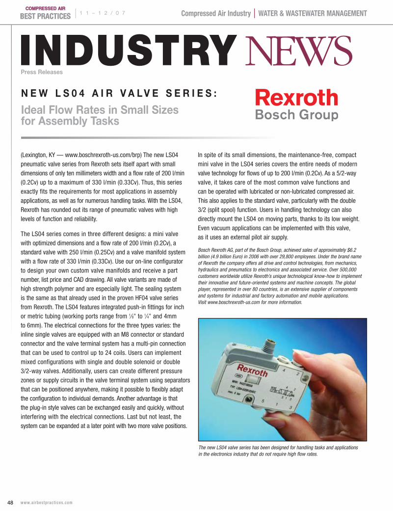
| 1 1 – 1 2 / 0 7
48 www.ai rbestpract ices .com
Compressed Air Industry | WATer & WAsTeWATer mAnAgemenT
INDUSTRY NEWSPress releases
(Lexington, KY — www.boschrexroth-us.com/brp) The new LS04 pneumatic valve series from Rexroth sets itself apart with small dimensions of only ten millimeters width and a flow rate of 200 l/min (0.2Cv) up to a maximum of 330 l/min (0.33Cv). Thus, this series exactly fits the requirements for most applications in assembly applications, as well as for numerous handling tasks. With the LS04, Rexroth has rounded out its range of pneumatic valves with high levels of function and reliability.
The LS04 series comes in three different designs: a mini valve with optimized dimensions and a flow rate of 200 l/min (0.2Cv), a standard valve with 250 l/min (0.25Cv) and a valve manifold system with a flow rate of 330 l/min (0.33Cv). Use our on-line configurator to design your own custom valve manifolds and receive a part number, list price and CAD drawing. All valve variants are made of high strength polymer and are especially light. The sealing system is the same as that already used in the proven HF04 valve series from Rexroth. The LS04 features integrated push-in fittings for inch or metric tubing (working ports range from 1⁄8" to 1⁄4" and 4mm to 6mm). The electrical connections for the three types varies: the inline single valves are equipped with an M8 connector or standard connector and the valve terminal system has a multi-pin connection that can be used to control up to 24 coils. Users can implement mixed configurations with single and double solenoid or double 3/2-way valves. Additionally, users can create different pressure zones or supply circuits in the valve terminal system using separators that can be positioned anywhere, making it possible to flexibly adapt the configuration to individual demands. Another advantage is that the plug-in style valves can be exchanged easily and quickly, without interfering with the electrical connections. Last but not least, the system can be expanded at a later point with two more valve positions.
In spite of its small dimensions, the maintenance-free, compact mini valve in the LS04 series covers the entire needs of modern valve technology for flows of up to 200 l/min (0.2Cv). As a 5/2-way valve, it takes care of the most common valve functions and can be operated with lubricated or non-lubricated compressed air. This also applies to the standard valve, particularly with the double 3/2 (split spool) function. Users in handling technology can also directly mount the LS04 on moving parts, thanks to its low weight. Even vacuum applications can be implemented with this valve, as it uses an external pilot air supply.
Bosch Rexroth AG, part of the Bosch Group, achieved sales of approximately $6.2 billion (4.9 billion Euro) in 2006 with over 29,800 employees. Under the brand name of Rexroth the company offers all drive and control technologies, from mechanics, hydraulics and pneumatics to electronics and associated service. Over 500,000 customers worldwide utilize Rexroth’s unique technological know-how to implement their innovative and future-oriented systems and machine concepts. The global player, represented in over 80 countries, is an extensive supplier of components and systems for industrial and factory automation and mobile applications. Visit www.boschrexroth-us.com for more information.
n e w L s 0 4 a i r V a L V e s e r i e s :
ideal Flow rates in small sizes for assembly tasks
The new LS04 valve series has been designed for handling tasks and applications in the electronics industry that do not require high flow rates.
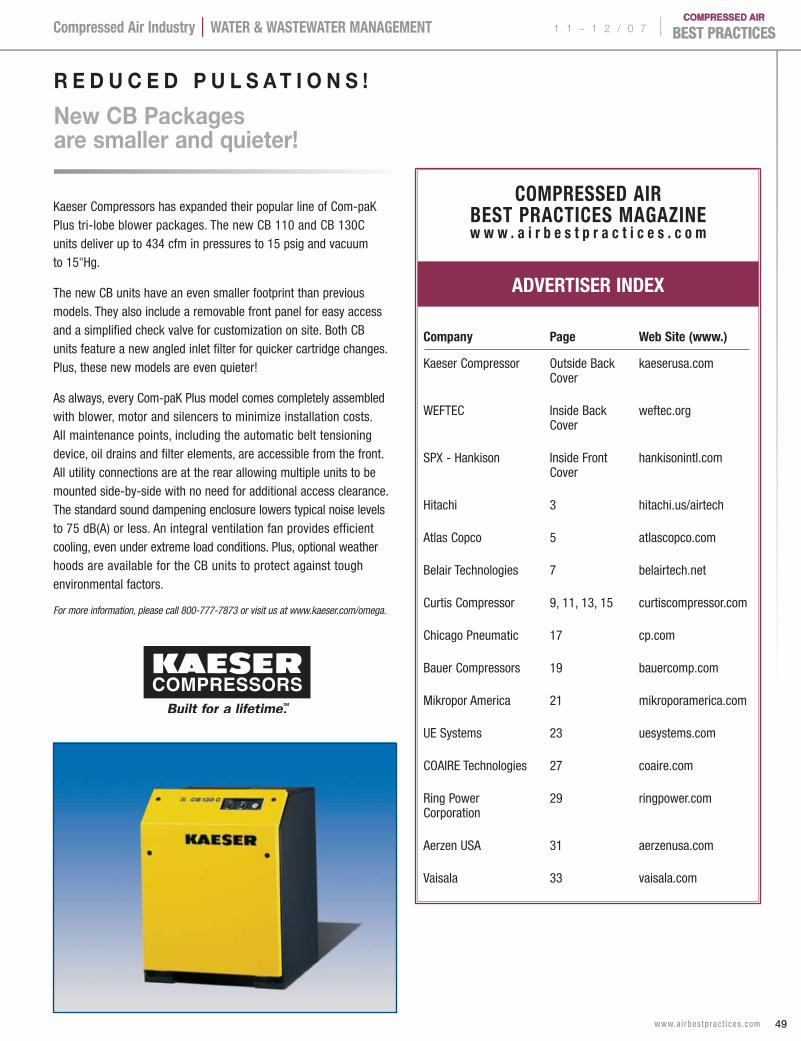
1 1 – 1 2 / 0 7 |
49 www.ai rbestpract ices .com
Compressed Air Industry | WATer & WAsTeWATer mAnAgemenT
COmPresseD AIr BesT PrACTICes mAgAzInew w w . a i r b e s t p r a c t i c e s . c o m
ADverTIser InDeX
Company Page Web site (www.)
Kaeser Compressor Outside Back kaeserusa.com Cover
WEFTEC Inside Back weftec.org Cover
SPX - Hankison Inside Front hankisonintl.com Cover
Hitachi 3 hitachi.us/airtech
Atlas Copco 5 atlascopco.com
Belair Technologies 7 belairtech.net
Curtis Compressor 9, 11, 13, 15 curtiscompressor.com
Chicago Pneumatic 17 cp.com
Bauer Compressors 19 bauercomp.com
Mikropor America 21 mikroporamerica.com
UE Systems 23 uesystems.com
COAIRE Technologies 27 coaire.com
Ring Power 29 ringpower.com Corporation
Aerzen USA 31 aerzenusa.com
Vaisala 33 vaisala.com
Kaeser Compressors has expanded their popular line of Com-paK Plus tri-lobe blower packages. The new CB 110 and CB 130C units deliver up to 434 cfm in pressures to 15 psig and vacuum to 15"Hg.
The new CB units have an even smaller footprint than previous models. They also include a removable front panel for easy access and a simplified check valve for customization on site. Both CB units feature a new angled inlet filter for quicker cartridge changes. Plus, these new models are even quieter!
As always, every Com-paK Plus model comes completely assembled with blower, motor and silencers to minimize installation costs. All maintenance points, including the automatic belt tensioning device, oil drains and filter elements, are accessible from the front. All utility connections are at the rear allowing multiple units to be mounted side-by-side with no need for additional access clearance. The standard sound dampening enclosure lowers typical noise levels to 75 dB(A) or less. An integral ventilation fan provides efficient cooling, even under extreme load conditions. Plus, optional weather hoods are available for the CB units to protect against tough environmental factors.
For more information, please call 800-777-7873 or visit us at www.kaeser.com/omega.
r e d u c e d P u L s a t i o n s !
new cB Packages are smaller and quieter!
| 1 1 – 1 2 / 0 7
50 www.ai rbestpract ices .com
Compressed Air Industry | WATer & WAsTeWATer mAnAgemenT
J o b O p e n i n g s i n t h e C o m p r e s s e d A i r I n d u s t r y
regionaL saLes
Managergrs · grs FLuid handLing
GRS Fluid Handling is working
on a search for a client — a com-
pressor manufacturer serving a
variety of industries worldwide.
They|are a strong company with a
track record of customer satisfac-
tion. This position, as a Regional
Sales Manager, will sell Industrial
Air Compressors throughout a
Northwestern US territory.
requirements:
• 2-5yearssalesexperience(***Must have channel management experience)
• KnowledgeofCaliforniaaccountbase as well as surrounding areas
• Someapplicationsexperience,preferably dealing with compressed air systems
• Astrongpersonalityandattitude
• Acollegedegreeisstrongly preferred for this position.
This is a highly visible position
that offers a chance for advance-
ment, great benefits, challenge
and opportunities with a strong,
stable company.
For more information, please
contact Joe Bertolami, GRS,
tel. 440-684-6150 ext. 3007,
email jbertolami@grsrecruiting.
com; www.grsrecruiting.com.
saLes engineer
grs · grs FLuid handLing
GRS Fluid Handling is working
on a search with a client who is
a top manufacturer of compressed
air products and equipment —
to search for a top technical sales-
man. This position will oversee
sales for a territory centered
in Birmingham, AL., and be
responsible for the total sales
performance of their product line.
requirements:
• 3-5yearsexperiencesellingtechnical industrial products, ***preferably compressors, with a history of identifying and penetrating new accounts
• UnderstandingoftheAlabamabusiness community and potential compressor accounts
• Theabilitytotravelasneeded
• Desireandhungertomove forward and build a career
This position offers a chance to
move into a highly visible role
with distinct responsibilities and
challenges. It offers the chance
to work autonomously and grow
a business segment. Our client
is well respected with a great
product and talented support staff.
For more information, please
contact Joe Bertolami, GRS,
tel. 440-684-6150 ext. 3007,
email jbertolami@grsrecruiting.
com; www.grsrecruiting.com.
COmPresseD AIr BesT PrACTICes
JOB mArKeT ADverTIsIng rATes
Magazine ads For smaller classified-type ads use
the following rates per column inch:
1x per year: $94.00* 3x per year: $90.00* 12x per year: $84.00* *reversed ads = 1.5x normal price
Add $50.00 to post the job opening on www.airbestpractices.com when you purchase an ad in the magazine
Contact Patricia Smith for 4 color full page, 1/2 page and 1/3 page ad rates
Small Price Per Bulk Price Per Qty. Posting Qty. Posting 1 $250 5-9 $185 2 230 10-24 170 3 210 25-49 150 4 195 50+ 135
[email protected], tel: 251-510-2598
saLes engineer
nashViLLe,tn
AIM Power & Fluids, a Sullair Industrial Compressor Distributor, located in the booming economy of middle Tennessee has an imm-ediate need for an experienced outside sales engineer.
Nashville is a great place to work and live, and AIM offers an EXCELLENT compensation and benefits package.
Interested candidates should please send resume to John Elias at: [email protected]

Submit your abstracts online at www.wef.org/conferencestraining/conferences/weftec.For abstract submission guidelines and detailed information, visit www.weftec.org/program
81st Annual Water Environment Federation Technical Exhibition and Conference
McCormick Place | Chicago, Illinois, USAConference | October 18-22, 2008Exhibition | October 19-22, 2008
call for abstracts
WEFTEC.08 Topics Include:A. Leading Edge ResearchB. Industrial Issues and TechnologyC. Municipal Wastewater TreatmentD. Facility Operations and MaintenanceE. Collection SystemsF. Stormwater ManagementG. Surface Water Quality and EcologyH. Residuals and Biosolids ManagementI. Utility ManagementJ. Small Community and Decentralized System Design and ManagementK. Water Reclamation and ReuseL. GIS and Information Management Systems, Instrumentation and AutomationM. Groundwater – Contemporary Issues in Contaminants, Remediation, Recharge, and Water RegulationN. Young Professionals Improving the Water EnvironmentO. Energy Conservation and Management: New Concepts and ApproachesP. Water Environment Technical and Management Approaches for Reduction of Greenhouse Gas Emissions (International Sessions)Q. Financial Instruments for Greenhouse
Gas Emissions Reductions (International Sessions)R. Planning for and Recovery from Natural Disasters-Water and Wastewater Infrastructure (International Sessions)S. Small Island Nations and Communities – Water, Wastes and Environmental Issues Faced Due to Growth, Development, and Tourism (International Sessions)T. Disinfection Practices for Water and WastewaterU. Sustainable Water Resources ManagementV. Management of Odors and Air EmissionsW. Odor and Corrosion Control in the Collection System: From the Pipes to the PlantX. Innovative Technologies and Solutions for Water and Wastewater Treatment and Water Resources ManagementY. Public Education and Communication: Changing our Mental Models – Learning New Ways to Talk About WaterZ. Microconstituents – What’s New and What’s NeededAA. Midwest IssuesBB. Workforce Professional DevelopmentCC. Laboratory Practices
Don’t miss your opportunity to submit your abstracts!Submittal deadline: December 3, 2007; Midnight, US Eastern Time Zone
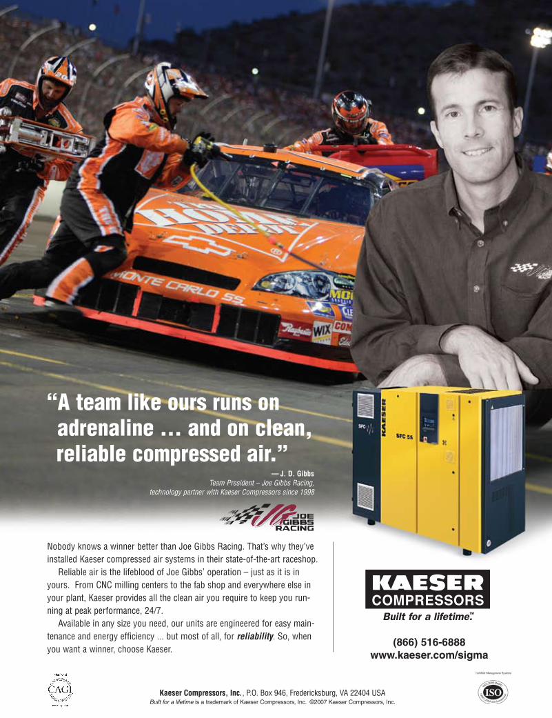
“A team like ours runs on adrenaline … and on clean, reliable compressed air.”
(866) 516-6888www.kaeser.com/sigma
COMPRESSORS
Nobody knows a winner better than Joe Gibbs Racing. That’s why they’veinstalled Kaeser compressed air systems in their state-of-the-art raceshop.
Reliable air is the lifeblood of Joe Gibbs’ operation – just as it is inyours. From CNC milling centers to the fab shop and everywhere else inyour plant, Kaeser provides all the clean air you require to keep you run-ning at peak performance, 24/7.
Available in any size you need, our units are engineered for easy main-tenance and energy efficiency ... but most of all, for reliability. So, whenyou want a winner, choose Kaeser.
Kaeser Compressors, Inc., P.O. Box 946, Fredericksburg, VA 22404 USABuilt for a lifetime is a trademark of Kaeser Compressors, Inc. ©2007 Kaeser Compressors, Inc.
— J. D. GibbsTeam President – Joe Gibbs Racing,
technology partner with Kaeser Compressors since 1998


![Dave Flagg - Treatment Building and Piping [Read-Only] · 2 separate Bio-filter out buildings, 2 separate blowers and 1 processing building along with connecting piping. Processing](https://img.pdfslide.us/doc/110x75/5f64a0551219011cbd744d50/dave-flagg-treatment-building-and-piping-read-only-2-separate-bio-filter-out.jpg)