Embed Size (px)
Citation preview
ADVANCED ENGINE MANAGEMENT INC. 2205 126th Street Unit A, Hawthorne, CA. 90250
Phone: (310) 484-2322 Fax: (310) 484-0152 http://www.aempower.com
Instruction Part Number: 10-4100 Rev 051705 2004 Advanced Engine Management, Inc.
Page 1
Installation Instructions for
30-4100 Gauge-Type UEGO Controller
WARNING:
!This installation is not for the electrically or mechanically challenged! Use this sensor with EXTREME caution! If you are uncomfortable with anything about this, please refer the installation to an AEM trained tuning shop or call 800-423-0046 for technical assistance. You should also visit the AEM Performance Electronics Forum at http://www.aempower.com NOTE: AEM holds no responsibility for any engine damage that results from the misuse of this product!
This product is legal in California for racing vehicles only and should
never be used on public highways.
Page 2
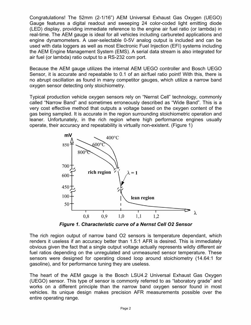
Congratulations! The 52mm (2-1/16”) AEM Universal Exhaust Gas Oxygen (UEGO) Gauge features a digital readout and sweeping 24 color-coded light emitting diode (LED) display, providing immediate reference to the engine air fuel ratio (or lambda) in real-time. The AEM gauge is ideal for all vehicles including carbureted applications and engine dynamometers. A user-selectable 0-5V analog output is included and can be used with data loggers as well as most Electronic Fuel Injection (EFI) systems including the AEM Engine Management System (EMS). A serial data stream is also integrated for air fuel (or lambda) ratio output to a RS-232 com port. Because the AEM gauge utilizes the internal AEM UEGO controller and Bosch UEGO Sensor, it is accurate and repeatable to 0.1 of an air/fuel ratio point! With this, there is no abrupt oscillation as found in many competitor gauges, which utilize a narrow band oxygen sensor detecting only stoichiometry. Typical production vehicle oxygen sensors rely on “Nernst Cell” technology, commonly called “Narrow Band” and sometimes erroneously described as “Wide Band”. This is a very cost effective method that outputs a voltage based on the oxygen content of the gas being sampled. It is accurate in the region surrounding stoichiometric operation and leaner. Unfortunately, in the rich region where high performance engines usually operate, their accuracy and repeatability is virtually non-existent. (Figure 1)
Figure 1. Characteristic curve of a Nernst Cell O2 Sensor
The rich region output of narrow band O2 sensors is temperature dependant, which renders it useless if an accuracy better than 1.5:1 AFR is desired. This is immediately obvious given the fact that a single output voltage actually represents wildly different air fuel ratios depending on the unregulated and unmeasured sensor temperature. These sensors were designed for operating closed loop around stoichiometry (14.64:1 for gasoline), and for performance tuning they are useless. The heart of the AEM gauge is the Bosch LSU4.2 Universal Exhaust Gas Oxygen (UEGO) sensor. This type of sensor is commonly referred to as “laboratory grade” and works on a different principle than the narrow band oxygen sensor found in most vehicles. Its unique design makes precision AFR measurements possible over the entire operating range.
Page 3
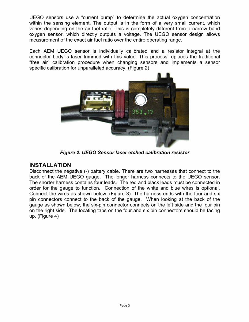
UEGO sensors use a “current pump” to determine the actual oxygen concentration within the sensing element. The output is in the form of a very small current, which varies depending on the air-fuel ratio. This is completely different from a narrow band oxygen sensor, which directly outputs a voltage. The UEGO sensor design allows measurement of the exact air fuel ratio over the entire operating range. Each AEM UEGO sensor is individually calibrated and a resistor integral at the connector body is laser trimmed with this value. This process replaces the traditional “free air” calibration procedure when changing sensors and implements a sensor specific calibration for unparalleled accuracy. (Figure 2)
Figure 2. UEGO Sensor laser etched calibration resistor
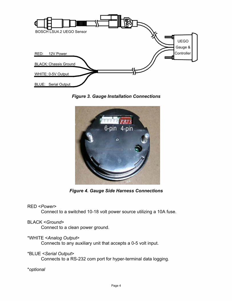
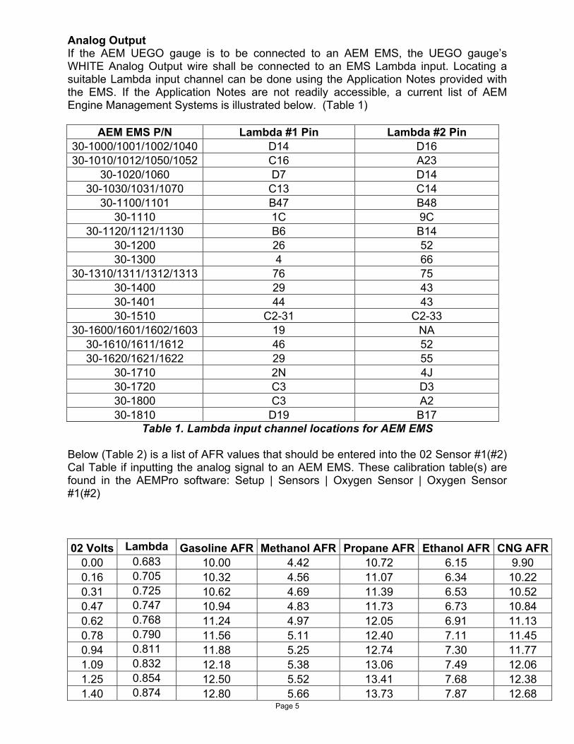
INSTALLATION Disconnect the negative (-) battery cable. There are two harnesses that connect to the back of the AEM UEGO gauge. The longer harness connects to the UEGO sensor. The shorter harness contains four leads. The red and black leads must be connected in order for the gauge to function. Connection of the white and blue wires is optional. Connect the wires as shown below. (Figure 3) The harness ends with the four and six pin connectors connect to the back of the gauge. When looking at the back of the gauge as shown below, the six-pin connector connects on the left side and the four pin on the right side. The locating tabs on the four and six pin connectors should be facing up. (Figure 4)
Page 4
12V Power
Chassis Ground
0-5V Output
Serial Output
BOSCH LSU4.2 UEGO Sensor
Controller
UEGOGauge &
RED:
BLACK:
WHITE:
BLUE:
Figure 3. Gauge Installation Connections
Figure 4. Gauge Side Harness Connections
RED <Power>
Connect to a switched 10-18 volt power source utilizing a 10A fuse. BLACK <Ground>
Connect to a clean power ground. *WHITE <Analog Output>
Connects to any auxiliary unit that accepts a 0-5 volt input. *BLUE <Serial Output>
Connects to a RS-232 com port for hyper-terminal data logging. *optional
Page 5
Analog Output If the AEM UEGO gauge is to be connected to an AEM EMS, the UEGO gauge’s WHITE Analog Output wire shall be connected to an EMS Lambda input. Locating a suitable Lambda input channel can be done using the Application Notes provided with the EMS. If the Application Notes are not readily accessible, a current list of AEM Engine Management Systems is illustrated below. (Table 1)
AEM EMS P/N Lambda #1 Pin Lambda #2 Pin 30-1000/1001/1002/1040 D14 D16 30-1010/1012/1050/1052 C16 A23
30-1020/1060 D7 D14 30-1030/1031/1070 C13 C14
30-1100/1101 B47 B48 30-1110 1C 9C
30-1120/1121/1130 B6 B14 30-1200 26 52 30-1300 4 66
30-1310/1311/1312/1313 76 75 30-1400 29 43 30-1401 44 43 30-1510 C2-31 C2-33
30-1600/1601/1602/1603 19 NA 30-1610/1611/1612 46 52 30-1620/1621/1622 29 55
30-1710 2N 4J 30-1720 C3 D3 30-1800 C3 A2 30-1810 D19 B17
Table 1. Lambda input channel locations for AEM EMS Below (Table 2) is a list of AFR values that should be entered into the 02 Sensor #1(#2) Cal Table if inputting the analog signal to an AEM EMS. These calibration table(s) are found in the AEMPro software: Setup | Sensors | Oxygen Sensor | Oxygen Sensor #1(#2) 02 Volts Lambda Gasoline AFR Methanol AFR Propane AFR Ethanol AFR CNG AFR
0.00 0.683 10.00 4.42 10.72 6.15 9.90 0.16 0.705 10.32 4.56 11.07 6.34 10.22 0.31 0.725 10.62 4.69 11.39 6.53 10.52 0.47 0.747 10.94 4.83 11.73 6.73 10.84 0.62 0.768 11.24 4.97 12.05 6.91 11.13 0.78 0.790 11.56 5.11 12.40 7.11 11.45 0.94 0.811 11.88 5.25 12.74 7.30 11.77 1.09 0.832 12.18 5.38 13.06 7.49 12.06 1.25 0.854 12.50 5.52 13.41 7.68 12.38 1.40 0.874 12.80 5.66 13.73 7.87 12.68
Page 6
1.56 0.896 13.12 5.80 14.07 8.07 12.99 1.72 0.918 13.44 5.94 14.41 8.26 13.31 1.87 0.939 13.74 6.07 14.73 8.45 13.61 2.03 0.960 14.06 6.21 15.08 8.64 13.93 2.18 0.981 14.36 6.35 15.40 8.83 14.22 2.34 1.003 14.68 6.49 15.74 9.02 14.54 2.50 1.025 15.00 6.63 16.09 9.22 14.86 2.65 1.045 15.30 6.76 16.41 9.41 15.15 2.81 1.067 15.62 6.90 16.75 9.60 15.47 2.96 1.087 15.92 7.04 17.07 9.79 15.77 3.12 1.109 16.24 7.18 17.42 9.98 16.08 3.28 1.130 16.54 7.31 17.74 10.17 16.38 3.43 1.152 16.86 7.45 18.08 10.36 16.70 3.59 1.173 17.18 7.59 18.42 10.56 17.02 3.74 1.194 17.48 7.73 18.75 10.75 17.31 3.90 1.216 17.80 7.87 19.09 10.94 17.63 4.06 1.236 18.10 8.00 19.41 11.13 17.93 4.21 1.258 18.42 8.14 19.75 11.32 18.24 4.37 1.280 18.74 8.28 20.10 11.52 18.56 4.52 1.301 19.04 8.41 20.42 11.70 18.86 4.68 1.322 19.36 8.56 20.76 11.90 19.17 4.84 1.343 19.66 8.69 21.08 12.09 19.47 4.99 1.365 19.98 8.83 21.43 12.28 19.79
Table 2. EMS Calibration Tables, P0 mode When connecting to AEM’s EMS, make sure to verify that the O2 #1 Gain option is set so the voltage from the O2 #1 Volts parameter matches the voltage input at the EMS from the O2 sensor. An easy way to do this is to disconnect the UEGO sensor from the UEGO gauge. When in this state, the UEGO gauge will output 2.35 volts. You can then adjust the O2 #1 Gain until the O2 #1 Volts display in AEMPro reads 2.35 volts. When connecting to a third party EFI system, the AEM UEGO gauge’s WHITE Analog Output wire shall be connected to the analog O2 sensor input of that system. Consult the documentation provided with the system for detailed instructions. Serial Output The serial output can be used for data logging when an EFI system is not accessible. To run the data stream, a RS-232 (DB-9) Female Receptacle shall be purchased.
1 2 3 4 5
6 7 8 9
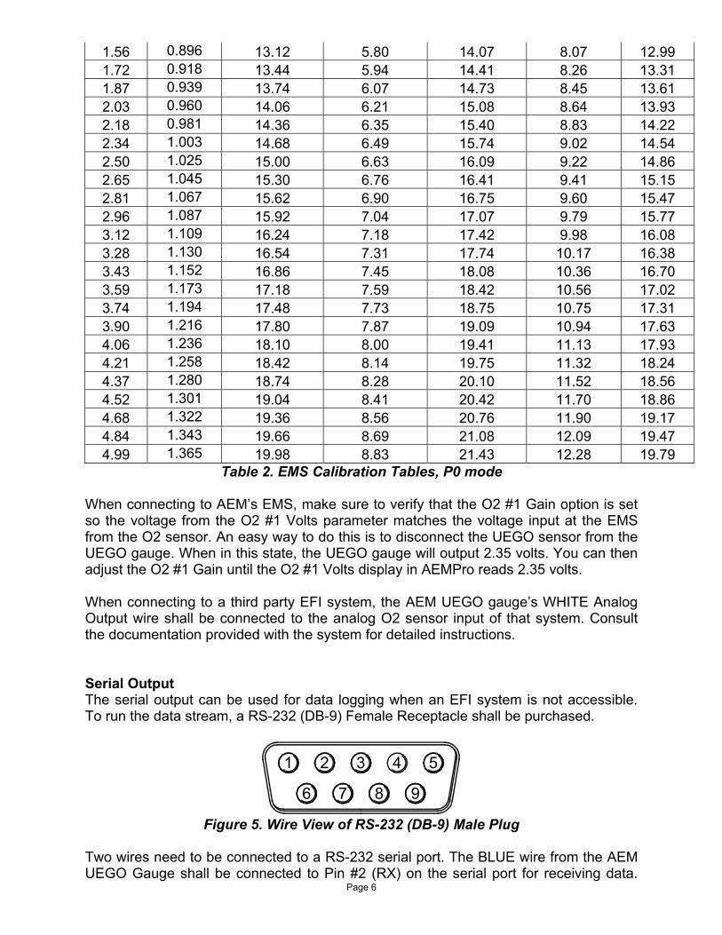
Figure 5. Wire View of RS-232 (DB-9) Male Plug Two wires need to be connected to a RS-232 serial port. The BLUE wire from the AEM UEGO Gauge shall be connected to Pin #2 (RX) on the serial port for receiving data.
Page 7
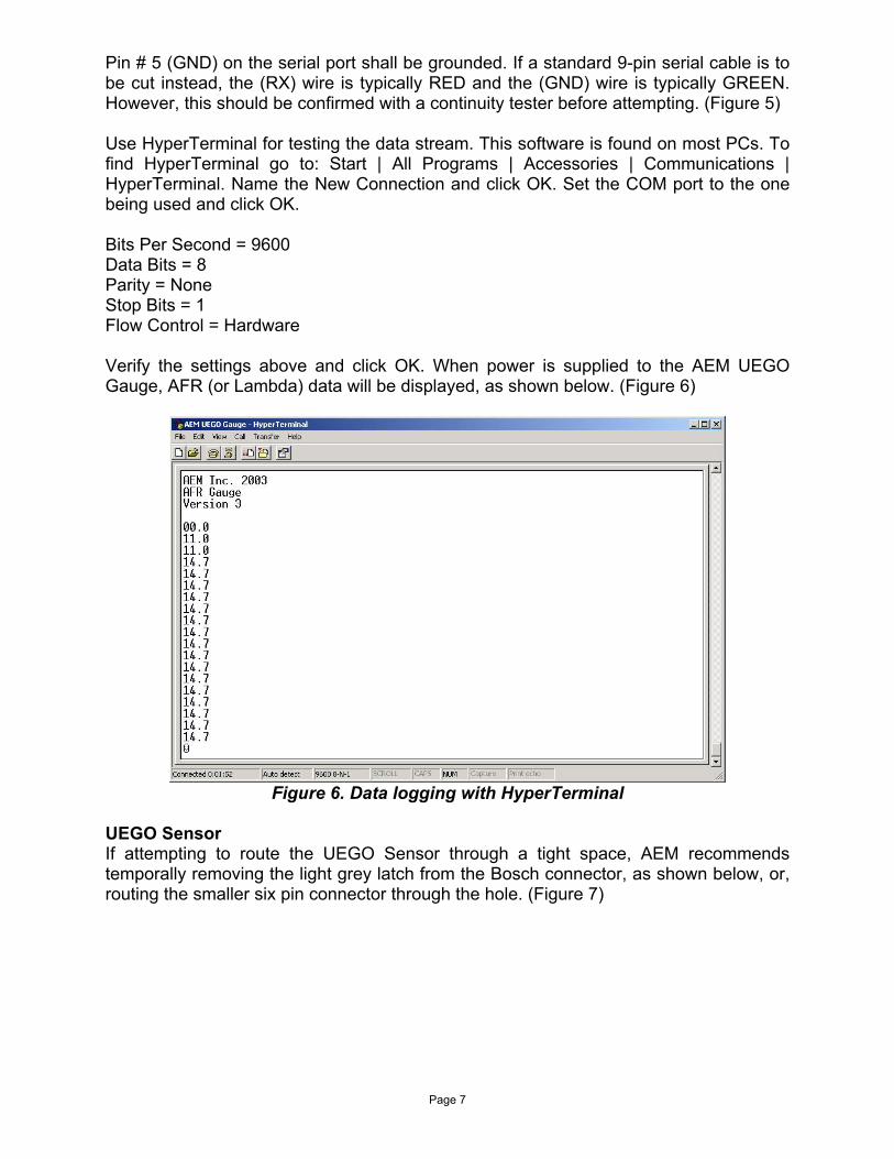
Pin # 5 (GND) on the serial port shall be grounded. If a standard 9-pin serial cable is to be cut instead, the (RX) wire is typically RED and the (GND) wire is typically GREEN. However, this should be confirmed with a continuity tester before attempting. (Figure 5) Use HyperTerminal for testing the data stream. This software is found on most PCs. To find HyperTerminal go to: Start | All Programs | Accessories | Communications | HyperTerminal. Name the New Connection and click OK. Set the COM port to the one being used and click OK. Bits Per Second = 9600 Data Bits = 8 Parity = None Stop Bits = 1 Flow Control = Hardware Verify the settings above and click OK. When power is supplied to the AEM UEGO Gauge, AFR (or Lambda) data will be displayed, as shown below. (Figure 6)
Figure 6. Data logging with HyperTerminal
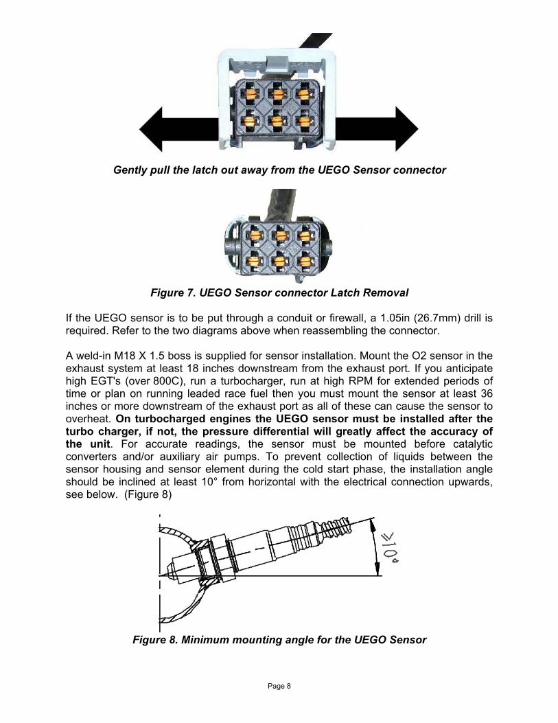
UEGO Sensor If attempting to route the UEGO Sensor through a tight space, AEM recommends temporally removing the light grey latch from the Bosch connector, as shown below, or, routing the smaller six pin connector through the hole. (Figure 7)
Page 8
Gently pull the latch out away from the UEGO Sensor connector
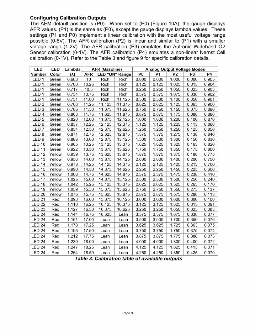
Figure 7. UEGO Sensor connector Latch Removal
If the UEGO sensor is to be put through a conduit or firewall, a 1.05in (26.7mm) drill is required. Refer to the two diagrams above when reassembling the connector. A weld-in M18 X 1.5 boss is supplied for sensor installation. Mount the O2 sensor in the exhaust system at least 18 inches downstream from the exhaust port. If you anticipate high EGT's (over 800C), run a turbocharger, run at high RPM for extended periods of time or plan on running leaded race fuel then you must mount the sensor at least 36 inches or more downstream of the exhaust port as all of these can cause the sensor to overheat. On turbocharged engines the UEGO sensor must be installed after the turbo charger, if not, the pressure differential will greatly affect the accuracy of the unit. For accurate readings, the sensor must be mounted before catalytic converters and/or auxiliary air pumps. To prevent collection of liquids between the sensor housing and sensor element during the cold start phase, the installation angle should be inclined at least 10° from horizontal with the electrical connection upwards, see below. (Figure 8)
Figure 8. Minimum mounting angle for the UEGO Sensor
Page 9
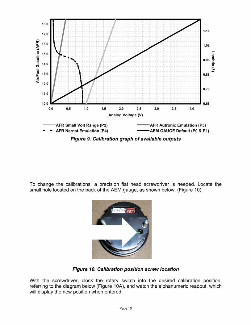
Configuring Calibration Outputs The AEM default position is (P0). When set to (P0) (Figure 10A), the gauge displays AFR values. (P1) is the same as (P0), except the gauge displays lambda values. These settings (P1 and P0) implement a linear calibration with the most useful voltage range possible (0-5V). The AFR calibration (P2) is linear and similar to (P1) with a smaller voltage range (1-2V). The AFR calibration (P3) emulates the Autronic Wideband O2 Sensor calibration (0-1V). The AFR calibration (P4) emulates a non-linear Nernst Cell calibration (0-1V). Refer to the Table 3 and figure 9 for specific calibration details.
LED LED Lambda AFR (Gasoline) Analog Output Voltage Modes Number Color (λ) AFR LED "ON" Range P0 P1 P2 P3 P4 LED 1 Green 0.683 10 Rich Rich 0.000 0.000 1.000 0.000 0.905 LED 1 Green 0.700 10.25 Rich Rich 0.125 0.125 1.025 0.013 0.904 LED 1 Green 0.717 10.5 Rich Rich 0.250 0.250 1.050 0.025 0.903 LED 1 Green 0.734 10.75 Rich Rich 0.375 0.375 1.075 0.038 0.902 LED 1 Green 0.751 11.00 Rich 11.125 0.500 0.500 1.100 0.050 0.901 LED 2 Green 0.768 11.25 11.125 11.375 0.625 0.625 1.125 0.063 0.900 LED 3 Green 0.786 11.50 11.375 11.625 0.750 0.750 1.150 0.075 0.890 LED 4 Green 0.803 11.75 11.625 11.875 0.875 0.875 1.175 0.088 0.880 LED 5 Green 0.820 12.00 11.875 12.125 1.000 1.000 1.200 0.100 0.870 LED 6 Green 0.837 12.25 12.125 12.375 1.125 1.125 1.225 0.113 0.860 LED 7 Green 0.854 12.50 12.375 12.625 1.250 1.250 1.250 0.125 0.850 LED 8 Green 0.871 12.75 12.625 12.875 1.375 1.375 1.275 0.138 0.840 LED 9 Green 0.888 13.00 12.875 13.125 1.500 1.500 1.300 0.150 0.830 LED 10 Green 0.905 13.25 13.125 13.375 1.625 1.625 1.325 0.163 0.820 LED 11 Green 0.922 13.50 13.375 13.625 1.750 1.750 1.350 0.175 0.800 LED 12 Yellow 0.939 13.75 13.625 13.875 1.875 1.875 1.375 0.188 0.775 LED 13 Yellow 0.956 14.00 13.875 14.125 2.000 2.000 1.400 0.200 0.750 LED 14 Yellow 0.973 14.25 14.125 14.375 2.125 2.125 1.425 0.213 0.700 LED 15 Yellow 0.990 14.50 14.375 14.625 2.250 2.250 1.450 0.225 0.600 LED 16 Yellow 1.008 14.75 14.625 14.875 2.375 2.375 1.475 0.238 0.410 LED 17 Yellow 1.025 15.00 14.875 15.125 2.500 2.500 1.500 0.250 0.240 LED 18 Yellow 1.042 15.25 15.125 15.375 2.625 2.625 1.525 0.263 0.170 LED 19 Yellow 1.059 15.50 15.375 15.625 2.750 2.750 1.550 0.275 0.137 LED 20 Yellow 1.076 15.75 15.625 15.875 2.875 2.875 1.575 0.288 0.113 LED 21 Red 1.093 16.00 15.875 16.125 3.000 3.000 1.600 0.300 0.100 LED 22 Red 1.110 16.25 16.125 16.375 3.125 3.125 1.625 0.313 0.091 LED 23 Red 1.127 16.50 16.375 16.625 3.250 3.250 1.650 0.325 0.083 LED 24 Red 1.144 16.75 16.625 Lean 3.375 3.375 1.675 0.338 0.077 LED 24 Red 1.161 17.00 Lean Lean 3.500 3.500 1.700 0.350 0.076 LED 24 Red 1.178 17.25 Lean Lean 3.625 3.625 1.725 0.363 0.075 LED 24 Red 1.195 17.50 Lean Lean 3.750 3.750 1.750 0.375 0.074 LED 24 Red 1.212 17.75 Lean Lean 3.875 3.875 1.775 0.388 0.073 LED 24 Red 1.230 18.00 Lean Lean 4.000 4.000 1.800 0.400 0.072 LED 24 Red 1.247 18.25 Lean Lean 4.125 4.125 1.825 0.413 0.071 LED 24 Red 1.264 18.50 Lean Lean 4.250 4.250 1.850 0.425 0.070
Table 3. Calibration table of available outputs
Page 10
10.0
11.0
12.0
13.0
14.0
15.0
16.0
17.0
18.0
0.0 0.5 1.0 1.5 2.0 2.5 3.0 3.5 4.0
Analog Voltage (V)
Air/
Fuel
Gas
olin
e (A
FR)
0.68
0.78
0.88
0.98
1.08
1.18
Lambda (λ)
AFR Small Volt Range (P2) AFR Autronic Emulation (P3)AFR Nernst Emulation (P4) AEM GAUGE Default (P0 & P1)
Figure 9. Calibration graph of available outputs
To change the calibrations, a precision flat head screwdriver is needed. Locate the small hole located on the back of the AEM gauge, as shown below. (Figure 10)
Figure 10. Calibration position screw location
With the screwdriver, clock the rotary switch into the desired calibration position, referring to the diagram below (Figure 10A), and watch the alphanumeric readout, which will display the new position when entered.
Page 11
P4
P3
P2
P1
P0
ROTARY SWITCH
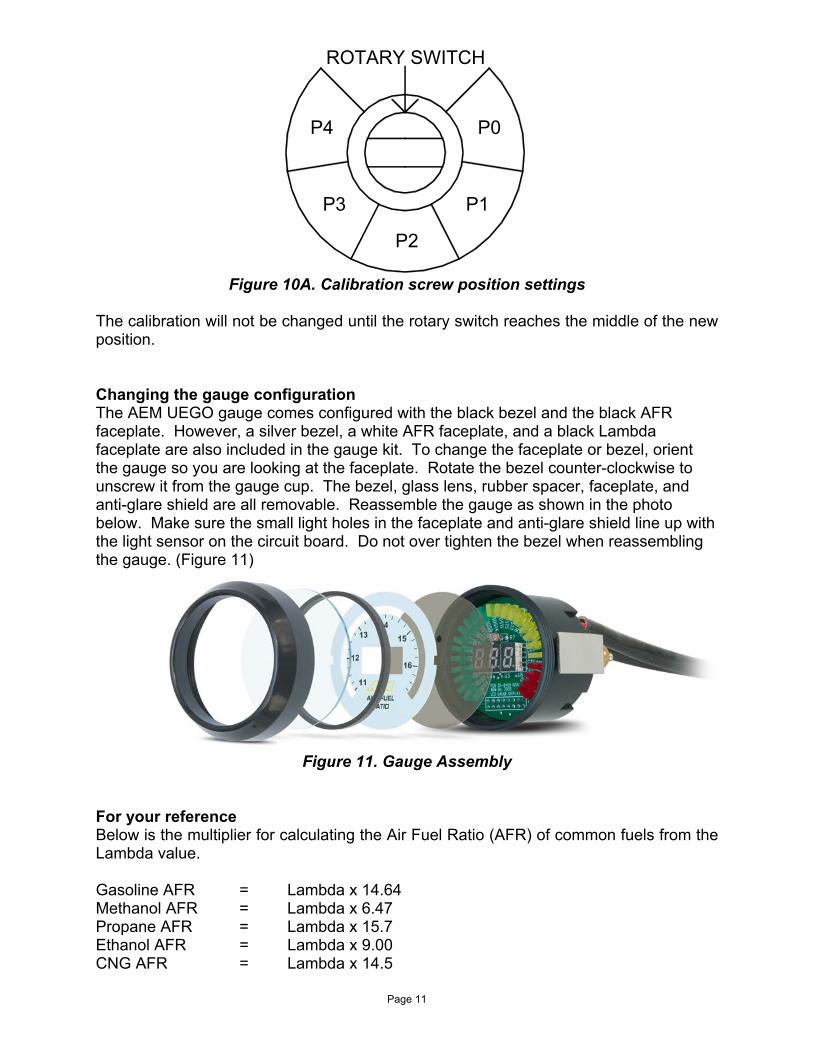
Figure 10A. Calibration screw position settings
The calibration will not be changed until the rotary switch reaches the middle of the new position. Changing the gauge configuration The AEM UEGO gauge comes configured with the black bezel and the black AFR faceplate. However, a silver bezel, a white AFR faceplate, and a black Lambda faceplate are also included in the gauge kit. To change the faceplate or bezel, orient the gauge so you are looking at the faceplate. Rotate the bezel counter-clockwise to unscrew it from the gauge cup. The bezel, glass lens, rubber spacer, faceplate, and anti-glare shield are all removable. Reassemble the gauge as shown in the photo below. Make sure the small light holes in the faceplate and anti-glare shield line up with the light sensor on the circuit board. Do not over tighten the bezel when reassembling the gauge. (Figure 11)
Figure 11. Gauge Assembly For your reference Below is the multiplier for calculating the Air Fuel Ratio (AFR) of common fuels from the Lambda value. Gasoline AFR = Lambda x 14.64 Methanol AFR = Lambda x 6.47 Propane AFR = Lambda x 15.7 Ethanol AFR = Lambda x 9.00 CNG AFR = Lambda x 14.5
Page 12
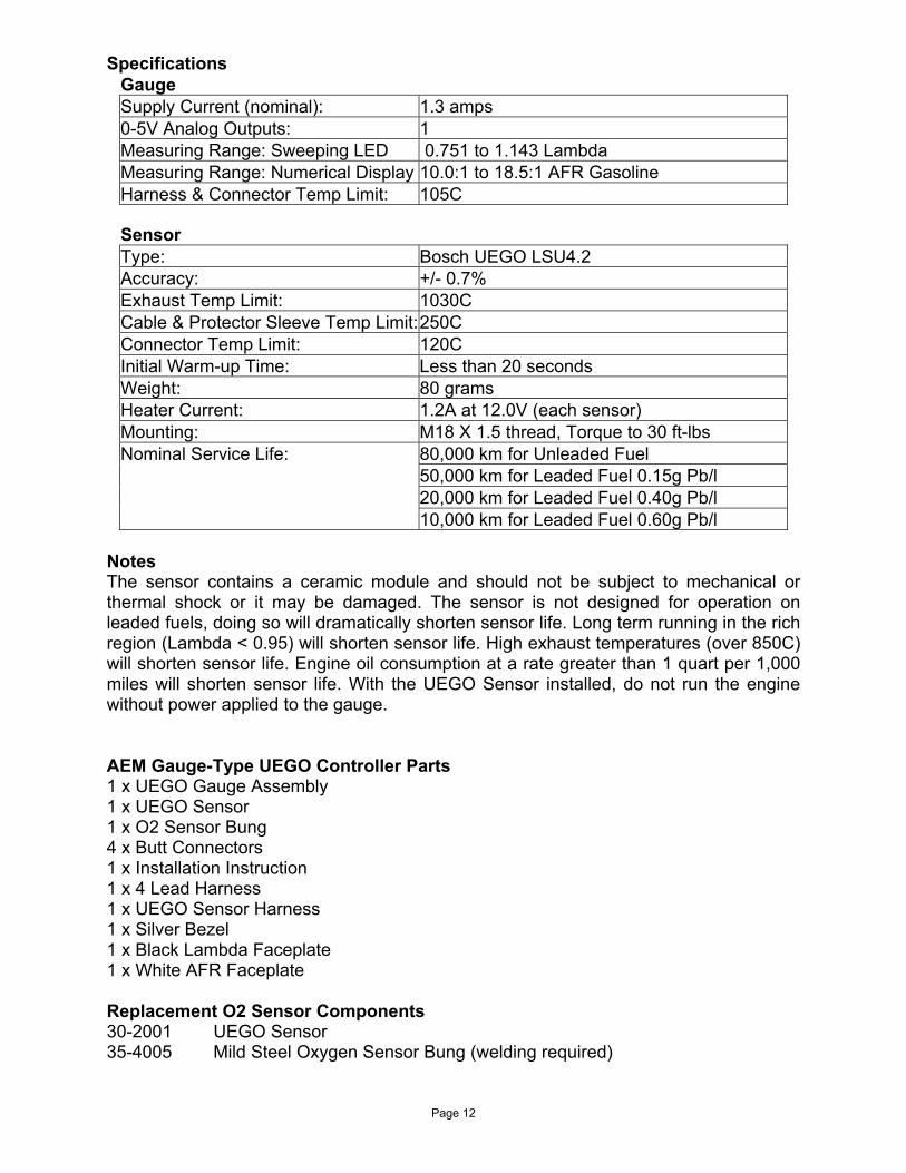
Specifications Gauge Supply Current (nominal): 1.3 amps 0-5V Analog Outputs: 1 Measuring Range: Sweeping LED 0.751 to 1.143 Lambda Measuring Range: Numerical Display 10.0:1 to 18.5:1 AFR Gasoline Harness & Connector Temp Limit: 105C
Sensor Type: Bosch UEGO LSU4.2 Accuracy: +/- 0.7% Exhaust Temp Limit: 1030C Cable & Protector Sleeve Temp Limit:250C Connector Temp Limit: 120C Initial Warm-up Time: Less than 20 seconds Weight: 80 grams Heater Current: 1.2A at 12.0V (each sensor) Mounting: M18 X 1.5 thread, Torque to 30 ft-lbs
80,000 km for Unleaded Fuel 50,000 km for Leaded Fuel 0.15g Pb/l 20,000 km for Leaded Fuel 0.40g Pb/l
Nominal Service Life: 10,000 km for Leaded Fuel 0.60g Pb/l
Notes The sensor contains a ceramic module and should not be subject to mechanical or thermal shock or it may be damaged. The sensor is not designed for operation on leaded fuels, doing so will dramatically shorten sensor life. Long term running in the rich region (Lambda < 0.95) will shorten sensor life. High exhaust temperatures (over 850C) will shorten sensor life. Engine oil consumption at a rate greater than 1 quart per 1,000 miles will shorten sensor life. With the UEGO Sensor installed, do not run the engine without power applied to the gauge. AEM Gauge-Type UEGO Controller Parts 1 x UEGO Gauge Assembly 1 x UEGO Sensor 1 x O2 Sensor Bung 4 x Butt Connectors 1 x Installation Instruction 1 x 4 Lead Harness 1 x UEGO Sensor Harness 1 x Silver Bezel 1 x Black Lambda Faceplate 1 x White AFR Faceplate Replacement O2 Sensor Components 30-2001 UEGO Sensor 35-4005 Mild Steel Oxygen Sensor Bung (welding required)
Page 13
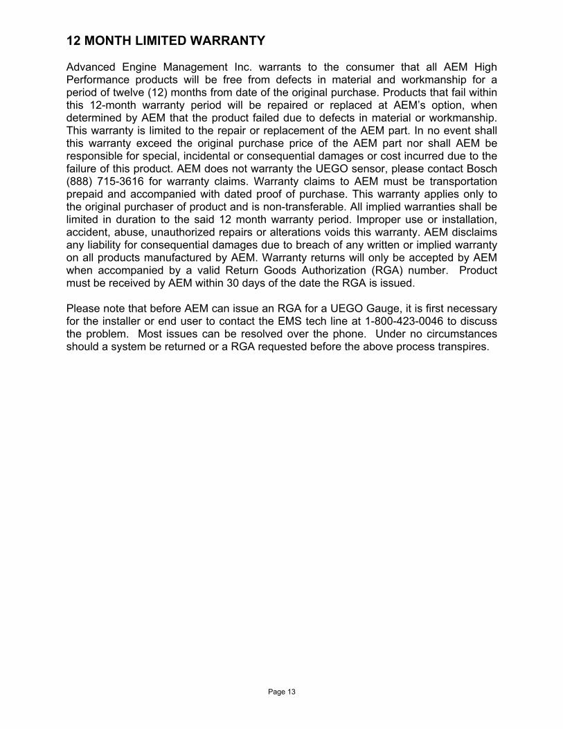
12 MONTH LIMITED WARRANTY Advanced Engine Management Inc. warrants to the consumer that all AEM High Performance products will be free from defects in material and workmanship for a period of twelve (12) months from date of the original purchase. Products that fail within this 12-month warranty period will be repaired or replaced at AEM’s option, when determined by AEM that the product failed due to defects in material or workmanship. This warranty is limited to the repair or replacement of the AEM part. In no event shall this warranty exceed the original purchase price of the AEM part nor shall AEM be responsible for special, incidental or consequential damages or cost incurred due to the failure of this product. AEM does not warranty the UEGO sensor, please contact Bosch (888) 715-3616 for warranty claims. Warranty claims to AEM must be transportation prepaid and accompanied with dated proof of purchase. This warranty applies only to the original purchaser of product and is non-transferable. All implied warranties shall be limited in duration to the said 12 month warranty period. Improper use or installation, accident, abuse, unauthorized repairs or alterations voids this warranty. AEM disclaims any liability for consequential damages due to breach of any written or implied warranty on all products manufactured by AEM. Warranty returns will only be accepted by AEM when accompanied by a valid Return Goods Authorization (RGA) number. Product must be received by AEM within 30 days of the date the RGA is issued. Please note that before AEM can issue an RGA for a UEGO Gauge, it is first necessary for the installer or end user to contact the EMS tech line at 1-800-423-0046 to discuss the problem. Most issues can be resolved over the phone. Under no circumstances should a system be returned or a RGA requested before the above process transpires.


![El ]uego: texto dramático y montaje](https://img.pdfslide.us/doc/110x75/62d60ffb3c1d70777f523000/el-uego-texto-dramtico-y-montaje.jpg)