Embed Size (px)
Citation preview

Aerospace Engineering 410 Aerospace Structural Dynamics 17 December 2014, San Diego, California
1
American Institute of Aeronautics and Astronautics
AE410 FEMAP/NASTRAN Finite Element Analysis
Project
Julian Bagtas1 and Lea Ricci2
San Diego State University, San Diego, California 92182
[Abstract] The objective of the assignment is to utilize
FEMAP/NASTRAN finite element analysis software to analyze model and
analyze normal modes and linear static analyses on a wing box structure.
The wing bodies to be analyzed will have two interior rib setups, one without
ribs and the other without. The models will be used to compare the
structural performance differences accompanied with using ribs in a wing
body.
Nomenclature E = Elastic modulus ν = Poisson’s ratio ρ = Density ωn = Natural frequency σ = Bending T = Torsion troot = top/bottom skin at root tcenter = top/bottom skin at center ttip = top/bottom skin at tip tweb = spar web thickness trib = rib thickness Aspar = spar cap area Hz = hertz p = pressure I. Introduction This report will analyze the use of ribs in a wing body using FEMAP/NASTRAN finite
element analysis software. Linear static analysis will be performed on the two unswept wing
bodies in addition to normal modes to compare and contrast the data with and without wing rib
usage. The differences in data being observed are in regards to the following topics:
● Bending modes ● Torsional modes ● Natural frequencies
________________________________________ 1 Undergraduate student, Aerospace Engineering, 5500 Campanile Drive, San Diego, CA 92182,
and AIAA Student Member. 2 Undergraduate student, Aerospace Engineering, 5500 Campanile Drive, San Diego, CA 92182,
and AIAA Student Member.

Aerospace Engineering 410 Aerospace Structural Dynamics 17 December 2014, San Diego, California
2
American Institute of Aeronautics and Astronautics
With elliptical loading scenario: ● Tip deflection ● Tip rotation ● Von-Mises stress distribution
The observed wing body was constructed using the following parameters and dimensions:
Figure 1Given dimensions of the modeled unswept wing
The wing also has the following material properties:
E = 70GPa
ρ = 2700Kg/m3
ν = 0.33
II. Normal Modes Analysis
Firstly, the wing box structure with no ribs was used to tabulate the natural frequencies ωn and
mode shapes. The following data will correspond to model A (without ribs) and model B (with
ribs) respectively.
A. Model A
1. First 30 natural frequencies and mode shapes

Aerospace Engineering 410 Aerospace Structural Dynamics 17 December 2014, San Diego, California
3
American Institute of Aeronautics and Astronautics
The following tables and figures show the first 30 natural frequencies and mode shapes of the
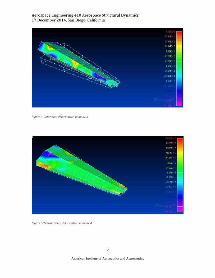
wing box structure with the absence of ribs. As seen in the figures, the deformations along the
wing body are primarily rotational and translational. The biggest change in deformation occurs
starting from the seventh mode. As seen in figure 8 the model seems to deform due to a
combination of torsion and bending. The following figures depict the original structure in a wire
frame, and the deformed structures are plotted with their respective frequencies along the body.
Table 1 Tabulated Natural frequencies with corresponding mode number

Aerospace Engineering 410 Aerospace Structural Dynamics 17 December 2014, San Diego, California
4
American Institute of Aeronautics and Astronautics
Figure 2 Translational deformation in mode 1
Figure 3 Translational and rotational deformation in mode 2
Aerospace Engineering 410 Aerospace Structural Dynamics 17 December 2014, San Diego, California
5
American Institute of Aeronautics and Astronautics
Figure 4 Rotational deformation in mode 3
Figure 5 Translational deformation in mode 4

Aerospace Engineering 410 Aerospace Structural Dynamics 17 December 2014, San Diego, California
6
American Institute of Aeronautics and Astronautics
Figure 6 Translational and rotational deformations in mode 5
Figure 7 Rotational deformation in mode 6

Aerospace Engineering 410 Aerospace Structural Dynamics 17 December 2014, San Diego, California
7
American Institute of Aeronautics and Astronautics
2. First bending and torsional mode
Figure 8 shows the plot of the frequencies on the wing in the first bending and torsion mode. The
frequencies range from high in the wing root area to low in towards the wing tip area as seen in
the visual representation of the deformed wing.
3. Fixed boundary condition
Once the frequencies and modes of the non-fixed wing model were tabulated and observed, the root of the wing was then fixed to a boundary condition. The fixed root wing body was then used to observe the same modes and frequencies as seen in the unconstrained wing body. The following table is a tabulation of the natural frequencies of the fixed wing.
Figure 8 Torsional and bending deformation in mode 7

Aerospace Engineering 410 Aerospace Structural Dynamics 17 December 2014, San Diego, California
8
American Institute of Aeronautics and Astronautics
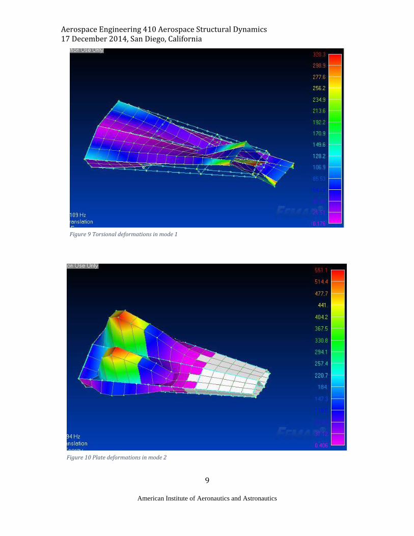
In comparison to the unconstrained wing body, one can expect different frequencies and vast differences in regards to deformations. It can be inferred that majority of the deformations seen in fixed wing will occur at the tip and have no translational deformations due to its constraints. These next figures are the visuals provided by FEMAP for the fixed boundary conditions.
Table 2 First 30 modes and corresponding frequencies for fixed boundary condition
Aerospace Engineering 410 Aerospace Structural Dynamics 17 December 2014, San Diego, California
9
American Institute of Aeronautics and Astronautics
Figure 9 Torsional deformations in mode 1
Figure 10 Plate deformations in mode 2

Aerospace Engineering 410 Aerospace Structural Dynamics 17 December 2014, San Diego, California
10
American Institute of Aeronautics and Astronautics
Figure 111 Bending deformations in mode 3
Figure 12 Plate and torsional deformations in mode 4

Aerospace Engineering 410 Aerospace Structural Dynamics 17 December 2014, San Diego, California
11
American Institute of Aeronautics and Astronautics
Figure 123 Plate and torsional deformations in mode 5
Figure 14 Plate and torsional deformations in mode 6

Aerospace Engineering 410 Aerospace Structural Dynamics 17 December 2014, San Diego, California
12
American Institute of Aeronautics and Astronautics
4. First three bending and torsional modes and corresponding frequencies
The first three bending and torsional modes occur at modes 2, 3, 4 and 1, 5, 6 respectively. The
plate deformations seen in the visual representations of the deformed wing are due to bending.
The deformed wing bodies can be seen in figures 9 through 13. The table 2 displays each natural
frequency for their respective bending or torsional mode.
5. Mesh refinement
Next, the number of elements was doubled along the wing to refine the mesh of the structure. The
causes of error are primarily due to the number of elements on the structure itself. As the number
of elements increases, so does the models ability to simulate a more finite analysis on the wing
body. Given that the simulation done by FEMAP will be more finite due to the increase in
elements, the accuracy of all other measurements and visualization of deformation modes should
increase as well. The table shown is the data collected pertaining to the mesh refinement for the
wing body. The following is the table of the frequencies and modes of the refined mesh wing.
Table 3 Natural frequencies and corresponding modes for mesh refinement

Aerospace Engineering 410 Aerospace Structural Dynamics 17 December 2014, San Diego, California
13
American Institute of Aeronautics and Astronautics
6. Plots of mode shapes for the first three bending and torsion models using converged mesh
The shapes for the 6 modes (3 bending and 3 torsional) should remain the same with the use of
the converged mesh. Although the shape looks the same, the converged mesh is more accurate
due to the reasons mentioned previously in part 5. The refined mesh models are as follows:
Figure 14 Mode 1 refined mesh
Figure 13 Mode 2 refined mesh

Aerospace Engineering 410 Aerospace Structural Dynamics 17 December 2014, San Diego, California
14
American Institute of Aeronautics and Astronautics
Figure 16 Mode 3 refined mesh
Figure 15 Mode 4 refined mesh

Aerospace Engineering 410 Aerospace Structural Dynamics 17 December 2014, San Diego, California
15
American Institute of Aeronautics and Astronautics
Figure 18 Mode 5 refined mesh
Figure 17 Mode 6 refined mesh

Aerospace Engineering 410 Aerospace Structural Dynamics 17 December 2014, San Diego, California
16
American Institute of Aeronautics and Astronautics
B. Model B 1. First 30 natural frequencies and mode shapes.
The following tables and figures show the first 30 natural frequencies and mode shapes of the
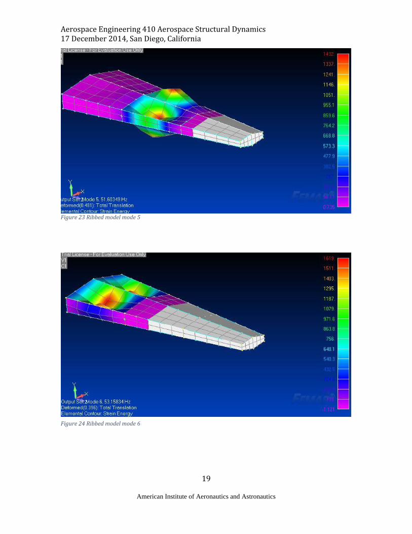
wing box structure with the presence of ribs. As seen in the figures, the deformations along the
wing body are primarily bending and torsional as opposed to the rotational and translational
deformations seen in the rib-less wing body. The biggest change in deformation occurs starting
from the seventh mode. As seen in figure 25 the model seems to deform due to a combination of
bending and torsion. The following figures depict the original structure in a wire frame, and the
deformed structures are plotted with their respective frequencies along the body. The next table
shows the ribbed model’s natural frequencies and their respective modes.
Table 4 Ribbed natural frequencies and corresponding modes

Aerospace Engineering 410 Aerospace Structural Dynamics 17 December 2014, San Diego, California
17
American Institute of Aeronautics and Astronautics
Figure 19 Ribbed model mode 1
Figure 20 Ribbed model mode 2

Aerospace Engineering 410 Aerospace Structural Dynamics 17 December 2014, San Diego, California
18
American Institute of Aeronautics and Astronautics
Figure 21 Ribbed model mode 3
Figure 22 Ribbed model mode 4
Aerospace Engineering 410 Aerospace Structural Dynamics 17 December 2014, San Diego, California
19
American Institute of Aeronautics and Astronautics
Figure 23 Ribbed model mode 5
Figure 24 Ribbed model mode 6

Aerospace Engineering 410 Aerospace Structural Dynamics 17 December 2014, San Diego, California
20
American Institute of Aeronautics and Astronautics
Figure 25 Ribbed model mode 7
2. First three bending and torsional modes with corresponding frequencies
Figures 19 through 24 show the plots of the frequencies on the wing on the first three bending and
torsional modes. Figures 19, 21 and 23 represent torsional deformations and figures 20, 22 and 24
represent the bending deformation modes.
3. Double spar cap area effects on natural frequencies for the first three bending and first
three torsional modes
Table 5 represents the natural frequencies of the wing body with a doubled spar cap area. Using
table 5 as a reference, one can see that the natural frequencies are relatively similar in comparison
to the original spar cap area. However, the increase in spar cap area is expected provide more
bending stiffness and rigidity due to the fact that the spar caps are placed longitudinally. Although
the data does not directly display this relation, it can be inferred that the bending stiffness should
increase with larger spar caps. Conversely, the spar cap area increase does not have the same
effect with torsional stiffness. The following figures are the first 7 modes with a doubled spar cap
area.

Aerospace Engineering 410 Aerospace Structural Dynamics 17 December 2014, San Diego, California
21
American Institute of Aeronautics and Astronautics
Table 5 Double spar cap area frequencies
Figure 26 Double spar cap area mode 1

Aerospace Engineering 410 Aerospace Structural Dynamics 17 December 2014, San Diego, California
22
American Institute of Aeronautics and Astronautics
Figure 27 Double spar cap area mode 2
Figure 28 Double spar cap area mode 3

Aerospace Engineering 410 Aerospace Structural Dynamics 17 December 2014, San Diego, California
23
American Institute of Aeronautics and Astronautics
Figure 29 Double spar cap area mode 4
Figure 30 Double spar cap area mode 5

Aerospace Engineering 410 Aerospace Structural Dynamics 17 December 2014, San Diego, California
24
American Institute of Aeronautics and Astronautics
Figure 31 Double spar cap area mode 6
Figure 32 Double spar cap area mode 7

Aerospace Engineering 410 Aerospace Structural Dynamics 17 December 2014, San Diego, California
25
American Institute of Aeronautics and Astronautics
4. Double rib thickness effects on natural frequencies for the first three bending and
torsional modes
It is to be expected that the rib thickness corresponds directly to the relationship with that of the
spar cap area. However, as opposed to increasing bending stiffness, the rib thickness adds
structural rigidity along the width of the wing, therefore increasing torsional stiffness. However,
the data does not represent this relationship. Instead, the frequency data is again similar to that of
the original ribbed wing model. The effect of the increase rib thickness can be seen in the
following table of natural frequencies.
III. Linear Static Analysis of Elliptical Loading
For this section, an elliptical loading scenario is given to observe tip deflections and behaviors.
The loading scenario given in figure 33 with a pressure of p=4.0 N/cm2.
1. Comparison and Analysis of wing box with and without ribs, in terms of max tip deflection
and rotation In terms of max tip deflection, the model with the ribs shows more tip deflection compared to that of the model without ribs. Conversely the model with ribs has less tip rotation than the model with no ribs. The differences with the tip deflections is correlated with the wing skin’s ability to deform. The wing skin is also constrained with the ribs in conjunction with the spars. The pairing of ribs and spars creates a body stiffer in torsion, thereby reducing tip rotation.
Figure 33 Elliptical loading scenario. Chord wise pressure distribution (top). Span wise pressure distribution (bottom)
Table 6 Double rib thickness effect on natural frequencies

Aerospace Engineering 410 Aerospace Structural Dynamics 17 December 2014, San Diego, California
26
American Institute of Aeronautics and Astronautics
2. Von-Mises Stress Distribution analysis
It is assumed that the contour plots for the Von-Mises stress distribution on the top and bottom
skin is not symmetric. Since the pressure distribution is acting on the top skin only, the force is
based on only one side making the distribution non-symmetric. In comparison to the wing body
without ribs, it can be inferred that the wing body with ribs has an added constraint to the wing
skin which causes the middle of the wing skin sections to deform more than the outside edges
constrained by the ribs and spars. The non-ribbed model has a more even deformation due to the
wing skin’s lack of constraints. The following figures represent the deformations across the wing.
Figure 34 Von-Mises distribution due to pressure force, ribbed model
Figure 35 Von-Mises distribution, non-ribbed model

Aerospace Engineering 410 Aerospace Structural Dynamics 17 December 2014, San Diego, California
27
American Institute of Aeronautics and Astronautics
3. Double spar cap area max deflection, max tip rotation and max stress analysis
Counterintuitively, when the spar cap area is doubled, the max deflection increases while the rotation and stress remain the same as previously tested. One may assume that an increase in the spar cap area will increase the tip deflection rigidity, however that is not the case
Figure 36 Doubled spar cap area, Von-Mises plot ribbed model
Figure 27 Double spar cap area, Von-Mises plot, non-ribbed model

Aerospace Engineering 410 Aerospace Structural Dynamics 17 December 2014, San Diego, California
28
American Institute of Aeronautics and Astronautics
4. Double rib thickness max deflection, max tip rotation and max stress analysis
Doubling the rib thickness also has little changes to the previously tested model in terms of deflection, rotation and max stress. The changes that occurred are due to the increase in the area in which the wing skin is constrained to the ribs.
Figure 3828Von-Mises with double rib thickness

Aerospace Engineering 410 Aerospace Structural Dynamics 17 December 2014, San Diego, California
29
American Institute of Aeronautics and Astronautics
Figure 29 Von-Mises, double rib area, non-ribbed model
IV. Conclusion
When analyzing this particular wing body, the data proves that wing ribs are a primary wing
structure when constructing a stable and rigid wing body. As seen in the data collected above, the
wing ribs add structural rigidity and increase torsional stiffness. Although it can be argued that
wing ribs have a non-uniform Von-Mises stress distribution, it can be noted that the positive
structural performance of the ribs outweigh the negative aspects associated with including ribs in
a wing structure. Lastly, after investigating the effects of ribs on structural deformations under
static loads and on natural frequencies and modes, one may conclude that wing ribs are crucial to
wing structures.

Aerospace Engineering 410 Aerospace Structural Dynamics 17 December 2014, San Diego, California
30
American Institute of Aeronautics and Astronautics
References
Book 1P Singiresu S. Rao, Mechanical Vibrations, 5th ed., Prentice Hall, New York, 1 Lake Street, Upper Saddle River, NJ 07458. 2011
Student Workload Distribution
The student work load was evenly distributed amongst the FEMAP modeling and analysis as well
as the report formatting and content. Report formatting, wing body modelling, meshing and
normal mode analysis was done by Lea Ricci. The FEMAP model analysis, meshing and various
parts of normal mode analysis and linear static analysis was conducted by Julian Bagtas.
Although certain sections of the assignment are listed as the duties of a particular student, each
section was checked and reviewed by each partner to ensure that the whole assignment is a
collaborative effort.


