Embed Size (px)
Citation preview
1©2015 Emerson Climate Technologies, Inc.
Application Guidelines forK4 Refrigeration Copeland Scroll™ Compressors 2 - 9 Horsepower
AE4-1299 R19 June 2015
Safety Safety Instructions ................................................. 2 Safety Icon Explanation ........................................ 2 Instructions Pertaining to Risk of Electrical Shock, Fire, or Injury to Persons ........... 3 Safety Statements ................................................. 3Introduction Nomenclature ....................................................... 4 Digital Compressor Operation .............................. 4 How It Works ....................................................... 4 Operating Envelope .............................................. 4 Liquid Injection ...................................................... 4 Vapor Injection ....................................................... 5 Discharge Temperature Control Valve ................... 5 Installation of Valve ............................................... 5 Suggested Application Techniques........................ 5 Compressor or Valve Service ................................ 5 Accumulators ........................................................ 5 Superheat Requirements ...................................... 6 Crankcase Heaters ............................................... 6 Discharge Line Thermostat ................................... 6 Pressure Controls ................................................. 6 Pump Down Recommendations ............................ 6 IPR Valve ............................................................... 7 Motor Protection .................................................... 7 Compressor Oil Charge ........................................ 7 Oil Management Rack Applications ...................... 7 Discharge Muffl ers ................................................ 7 Compressor Tubing and Mounting ........................ 7 Starting Characteristics ......................................... 8 Fusite .................................................................... 8 Shell Temperature ................................................. 8 Connection Fittings ............................................... 8 Three Phase Scroll Compressors - Directional Dependence ...................................................... 8 Brief Power Interruptions ....................................... 8
Deep Vacuum Operation ....................................... 8 Assembly Line System Charging Procedure ......... 9 Unbrazing System Components ........................... 9 High Potential (Hipot) Testing ................................. 9 Copeland Scroll Functional Check ........................ 9 New Installation ..................................................... 9 Field Service ........................................................ 10 Figures & Tables ZF**K4 Envelope (R-22) ...................................... 11 ZF**K4 Envelope (R-134a) .................................. 11 ZF**K4 Envelope (R-404A / R-507/ R-407A / R-407C / R-448A / R-449A) ............................. 11 ZS**K4E Envelope (R-134A) ............................... 11 ZS**K4E Envelope (R-404A/R-507) ..................... 11 ZS**K4E Envelope (R-22) .................................... 11 Copeland Scroll K4 Liquid Injection ..................... 12 Copeland Scroll K4 Vapor Injection ...................... 12 Assembly Diagram ............................................... 13 OMB Electronic Oil Level Management System Installation and Service Instructions ................. 14 2-9 HP Copeland Scroll Rack Mounting ............... 15 2-9 HP Copeland Scroll Condensing Unit Mounting ........................................................... 15 Typical Suction/Injection Tubing ........................... 16 Motor Terminal (Fusite) Connections for Single Phase and Three Phase Scrolls .......................... 16 Scroll Wiring Schematic ....................................... 17 Capillary Tubes For Liquid Injection ..................... 18 Crankcase Heaters .............................................. 18 Conduit Ready Heater Terminal Box Kits ............. 18 Discharge Line Thermostat Kits ........................... 19 Low and High Pressure Control Settings for ZF*K4(E) & ZS*K4(E) ....................................... 19 Oil Charges .......................................................... 19
TABLE OF CONTENTSSection Page Section Page

2©2015 Emerson Climate Technologies, Inc.
AE4-1299 R19
Safety InstructionsCopeland Scroll™ compressors are manufactured according to the latest U.S. and European Safety Standards. Particular emphasis has been placed on the user's safety. Safey icons are explained below and safety instructions applicable to the products in this bulletin are grouped on page 3. These instructions should be retained throughout the lifetime of the compressor. You are strongly advised to follow these safety instructions.
Safety Icon Explanation
DANGER indicates a hazardous situation which, if not avoided, will result in death or serious injury.
WARNING indicates a hazardous situation which, if not avoided, could result in death or serious injury.
CAUTION, used with the safety alert symbol, indicates a hazardous situation which, if not avoided, could result in minor or moderate injury.
NOTICE is used to address practices not related to personal injury.
CAUTION, without the safety alert symbol, is used to address practices not related to personal injury.
DANGER
WARNING
CAUTION
NOTICE
CAUTION
3©2015 Emerson Climate Technologies, Inc.
AE4-1299 R19
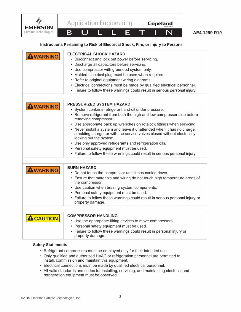
ELECTRICAL SHOCK HAZARD• Disconnect and lock out power before servicing. • Discharge all capacitors before servicing. • Use compressor with grounded system only. • Molded electrical plug must be used when required. • Refer to original equipment wiring diagrams. • • Failure to follow these warnings could result in serious personal injury.
PRESSURIZED SYSTEM HAZARD• System contains refrigerant and oil under pressure.• Remove refrigerant from both the high and low compressor side before
removing compressor. • • Never install a system and leave it unattended when it has no charge,
a holding charge, or with the service valves closed without electrically locking out the system.
• Use only approved refrigerants and refrigeration oils. • Personal safety equipment must be used. • Failure to follow these warnings could result in serious personal injury.
BURN HAZARD• Do not touch the compressor until it has cooled down. • Ensure that materials and wiring do not touch high temperature areas of
the compressor. • Use caution when brazing system components. • Personal safety equipment must be used. • Failure to follow these warnings could result in serious personal injury or
property damage.
COMPRESSOR HANDLING• Use the appropriate lifting devices to move compressors. • Personal safety equipment must be used. • Failure to follow these warnings could result in personal injury or
property damage.
Safety Statements• Refrigerant compressors must be employed only for their intended use. •
install, commission and maintain this equipment. • • All valid standards and codes for installing, servicing, and maintaining electrical and
refrigeration equipment must be observed.
Instructions Pertaining to Risk of Electrical Shock, Fire, or Injury to Persons
WARNING
WARNING
WARNING
CAUTION

4©2015 Emerson Climate Technologies, Inc.
AE4-1299 R19
Introduction
The Copeland Scroll™ K4 compressor represents the second generation of compliant scroll technology for the refrigeration industry. Four major changes have been incorporated compared to the previous K3 offering:
• Revised scroll form - Specifi cally designed to achieve the higher compression ratios typically found in refrigeration applications
• Addition of Dynamic Discharge Valve - Provides improved energy effi ciency when operating at high compression ratio conditions
• Modifi ed Injection System - Enables the scroll to accept either liquid or vapor injection depending on system design
• DU Drive Bearing - This Tefl on impregnated bronze bearing provides improved reliability
These changes result in a compressor that is suitable for the most demanding refrigeration applications with effi ciencies comparable to the industry standard Discus™ compressor.
Nomenclature The Copeland Scroll compressor model numbers include the nominal capacity at standard 60Hz ARI rating conditions. Please refer to product literature for model number details.
Operating EnvelopeK4 models can be used with a variety of refrigerants depending on the model selected and the lubricant used:
Model Refrigerant LubricantZS, ZF R-22 MOZS, ZF R-404A, R-507, R-134A, R-22 POE
ZF R-407C,R-407A,R-407F, R-448A, R-449A POE
See Form 93-11 for a complete list of all Emersonapproved refrigerants and lubricants.
CAUTIONPOE must be handled carefully and the proper protective equipment (gloves, eye protection, etc.) must be used when handling POE lubricant. POE must not come into contact with any surface or material that might be harmed by POE, including without limitation, certain polymers (e.g. PVC/CPVC and polycarbonate).
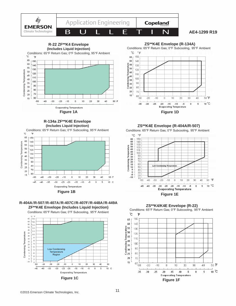
The ZF and ZS model families are intended for refrigeration type duty. The approved operating
envelopes for these models are depicted in Figures 1A through 1F, which can be found at the end of this bulletin.
It must be noted that the ZF model when operated at low evaporator temperatures requires some form of injection to prevent overheating. Either liquid or vapor injection is suffi cient for moderate condensing temperatures. However, depending on the refrigerant used, evaporating temperature and condensing temperature, liquid injection is required.
Liquid InjectionThe low temperature scroll compressor is provided with an injection port suitable for connection to a source of liquid refrigerant. Internally, this port is connected to an inner pocket of the scroll mechanism. Since this pocket is separated from the suction inlet, no loss of capacity or mass fl ow results from injecting at this point.
Refrigerant injected in this manner must include the system components listed on the next page. Failure to provide these components can result in liquid refrigerant completely fi lling the scroll during an “off” cycle. When power is reapplied in this condition, the hydraulic effect produced can result in pressures high enough to cause permanent damage to the compressor. It is a condition of warranty that these components are properly installed, whenever liquid or vapor injection is used.
• Capillary Tube - Liquid must be fed through an appropriate capillary tube as defi ned in Table 2, which can be found at the end of this bulletin. NOTE: Not required if DTC valve is used.
• Solenoid Valve - A solenoid valve with a minimum .109 inch orifi ce must be provided in the injection circuit that opens whenever the compressor is operative or cooling is required during pumpdown. The solenoid must be closed when the compressor is cycled off. NOTE: Not required if DTC valve is used.
• Current Sensing Relay - To prevent the solenoid from remaining open during a “motor protector trip” a current sensing relay must be provided that senses whenever the compressor is “off” and closes the solenoid to stop injection. NOTE: Not required if DTC valve is used
The following components are not required, but they are recommended for liquid injection.
• Sight Glass - A sight glass just before the capillary tube inlet is recommended to allow visual inspection for the presence of liquid refrigerant.
• Filter/Drier - A fi lter/drier installed in the injection circuit is recommended to avoid the possibility of capillary tube blockage due to contaminants.

5©2015 Emerson Climate Technologies, Inc.
AE4-1299 R19
Figure 2 is a representation of a typical system with these components.
The advantage of this type of injection system is that it tends to be self regulating i.e., as the pressure differential across the capillary tube increases, the amount of liquid fed to the compressor also increases. Since more cooling is needed at high compression ratio conditions, this “automatic” increase in liquid feed is exactly what is needed.
For the liquid injection system to be effective, a minimum of 5°F sub-cooled liquid at the capillary inlet is required. However, DO NOT use mechanically cooled subcooled liquid. The cap tube will be oversized under this condition and will dilute the oil in the compressor crankcase.
NOTE: Use of R-407a and R-407c with capillary tubes is not approved – see Discharge Temp Control Valve section for proper use.
Vapor InjectionEmerson has developed the ZF**KVE low temperature models to take advantage of the system effi ciency benefi t due to subcooling the liquid being feed to the evaporator. Figure 3 is a representation of this type of system. However, it is beyond the scope of this bulletin to provide details of the proper application of vapor-injected systems. Please refer to AE 4-1327 for additional information on "Economized Vapor Injection" systems.
DISCHARGE TEMPERATURE CONTROL VALVEIntroductionThe purpose of the DTC valve is to eliminate the need for a capillary tube on the 2 through 9 horsepower "ZF" scroll model family.
The DTC valve is approved for all refrigerants in this product range. A DTC valve must be used for ZF**K4E applications with R-407C, R-407A, R-448A and R-449A.
Kit Number Size Notes998-0500-00 3/8" Sweat Tube998-0500-01 1/4" Flare
Valve Specifi cationsOpening Setpoint: 193°F ±5°F Liquid Line Connection: 3/8” (9.5mm)
Installation of Valve (see Figure 4)The valve bulb must be installed in the top cap thermal well to adequately control scroll temperatures. The valve should be tightened on the injection fi tting to a torque of 216-245 in. lbs. (24.4 - 27.7 Nm). A 90° orientation on the
valve is recommended, however it will function properly in any orientation. The capillary tube connecting the valve to the bulb should be positioned such that it does not contact the compressor during operation. Do not bend the capillary tube within 1” (25.4mm) of the valve.
The DTC Valve comes with an insulating cap. If this additional height from the cap is an issue, the valve cap could be replaced with high temperature insulation. This should be applied to insulate and protect the valves remote bulb assembly. This will reduce the total height requirement by 0.5” (12.7mm).
Suggested Application TechniquesFor the most effi cient thermal sensing, spread a thin fi lm of thermal grease around the DTC Valve bulb before installing into the top cap well. However for proper functioning of the valve this is not required.
At your discretion, fi eld serviceability can be improved by installing a shut-off valve in the liquid line just before the DTC Valve.
The valve requires a solid column of liquid. A liquid line sightglass could be applied to visually insure liquid fl ow.
Compressor Or Valve ServiceReplacing a ZF compressor using capillary tube, liquid injection solenoid, and current sensing relay: The ZF compressor and DTC Valve eliminates the need for the solenoid and current sensing relay. These devices may be left on if desired, but they are not required.
Replacing a ZF compressor using the DTC Valve:We recommend replacing both the DTC Valve and the compressor at the same time. If you wish to use the existing DTC Valve, the valve fi lter (pn 013-0119-00) should be cleaned and/or replaced.
Replacing a capillary tube on a ZF compressor:The DTC Valve is not backward compatible on compressors with no thermal well in the top cap. Replacement capillary tubes will be available through our PrimeSourceSM network.
Replacing a DTC Valve on a ZF compressors:Before replacing the DTC Valve, clean and/or change the fi lter to verify there is an unobstructed column of liquid to the valve.
Attention: The DTC sensing bulb should be installed by hand. The valve should push in with little force. Using a hammer or other tool could damange the bulb, thus changing the operation of the valve.

6©2015 Emerson Climate Technologies, Inc.
AE4-1299 R19
• Three Phase - Outdoor Only Crankcase heaters are required on three phase compressors when the system charge exceeds 10 lbs. See Table 3A.
The listed crankcase heaters are intended for use only where there is limited access. The heaters are not equipped for use with electrical conduit. Where applicable electrical safety codes require heater lead protection, a crankcase terminal box should be used. Recommended crankcase heater terminal box and cover kit numbers are listed in Table 3B. If there are any questions concerning their application, contact Emerson Climate Technologies Application Engineering.
Discharge Line ThermostatA discharge line thermostat is required in the compressor control circuit. The thermostats have a cut out setting that will insure discharge line temperatures below the 260°F maximum limit. It should be installed approximately 7 inches from the discharge tube outlet. If a service valve is installed at the discharge tube, the thermostat should be located 5 inches from the valve braze. For proper functioning in extremely low outdoor ambient conditions, it is recommended the thermostat should be insulated to protect it from a direct air stream.
Kits have been set up to include the TOD thermostat, retainer, and installation instructions. These thermostats must be used with 1/2” O.D. discharge lines to ensure proper thermal transfer and temperature control. They work with either 120 or 240 volt circuits, and are available with or without an alarm circuit capability. See Table 4 for a list of discharge line thermostat kit numbers.
Pressure ControlsBoth high and low pressure controls are required and the following set points are the minimum and maximum limits. See Table 5 for setpoints.
Pump Down RecommendationsRefrigeration scroll compressors use a low-leak discharge valve to prevent high-pressure backfl ow into the low side. Typically, this check valve prevents system pressures from equalizing and pump down can be achieved. However, during laboratory testing, we have observed a potential short cycling condition on the 2, 2 ½, 3, & 3 ½ Horsepower models. This phenomenon can be attributed to several factors:1. Location of low-pressure control sensor. If it is
located right at the suction inlet of the compressor, it will be more sensitive to pressure spikes.
2. Actual low-pressure setting. Refer to our recommended setting in Table 5. If the differential
AccumulatorsDue to the scroll’s inherent ability to handle liquid refrigerant in fl ooded start and defrost cycle operation conditions, accumulators may not be required. An accumulator is required on single compressor systems with charges over 10 lbs. On systems with defrost schemes or transient operations that allow prolonged, uncontrolled liquid return to the compressor, an accumulator is required unless a suction header of suffi cient volume to prevent liquid migration to the compressor is used.
Excessive liquid fl ood back or repeated fl ooded starts will dilute the oil in any compressor causing inadequate lubrication and bearing wear. Proper system design will minimize liquid fl oodback thereby ensuring maximum compressor life.
Superheat RequirementsIn order to assure that liquid refrigerant does not return to the compressor during the running cycle, attention must be given to maintaining proper superheat at the compressor suction inlet. Emerson recommends a minimum of 20°F (11°C) superheat, measured on the suction line 6 inches (152mm) from the suction valve, to prevent liquid refrigerant fl oodback.
Another method to determine if liquid refrigerant is returning to the compressor is to accurately measure the temperature difference between the compressor oil crankcase and the suction line. During continuous operation we recommend that this difference be a minimum of 50°F (27°C). This “crankcase differential temperature” requirement supersedes the minimum suction superheat requirement in the last paragraph. To measure oil temperature through the compressor shell, place a thermocouple on the bottom center (not the side) of the compressor shell and insulate from the ambient.
During rapid system changes, such as defrost or ice harvest cycles, this temperature difference may drop rapidly for a short period of time. When the crankcase temperature difference falls below the recommended 50°F (27°C), our recommendation is the duration should not exceed a maximum (continuous) time period of two minutes and should not go lower than a 25°F (14°C) difference.
Contact your Emerson Climate Technologies representative regarding any exceptions to the above requirements.
Crankcase Heaters• Single Phase
No crankcase heaters are required on single phase scroll compressors.

7©2015 Emerson Climate Technologies, Inc.
AE4-1299 R19
Note: If oil management problems are occuring, please refer to AE17-1320 or contact Emerson Climate Technologies Application Engineering.Discharge Muffl ersFlow through scroll compressors is continuous with relatively low pulsations. External muffl ers applied to piston compressors may not be required on the Copeland Scroll compressor. Due to system variability individual tests should be conducted by the system manufacturer to verify acceptable levels of sound and vibration.
Compressor Tubing and MountingCompressor mounting must be selected based on application. Consideration must be given to sound reduction and tubing reliability. Some tubing geometry or “shock loops” may be required to reduce vibration transferred from the compressor to external tubing.
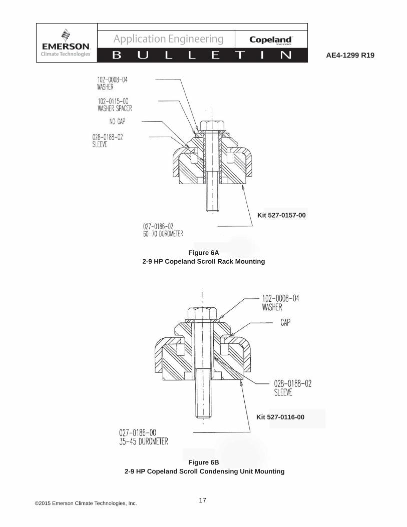
Mounting for Rack Systems – Specially designed rubber grommets are available for Copeland Scroll 2-9 H.P. scroll rack applications. These grommets are formulated from a high durometer material specifi cally designed for refrigeration applications. The high durometer limits the compressors motion thereby minimizing potential problems of excessive tubing stress. Suffi cient isolation is provided to prevent vibration from being transmitted to the mounting structure. This mounting arrangement is recommended for multiple compressor rack installations. See Figure 6A for a detail of this mounting system.
NOTICEThe use of standard soft grommets is not recommended for most Copeland Scroll rack installations. These “softer” mounts allow for excessive movement that will result in tube breakage unless the entire system is properly designed.
Condensing Units – For 2-9 H.P. Copeland Scroll condensing unit applications soft mounts are recommended. See Figure 6B.
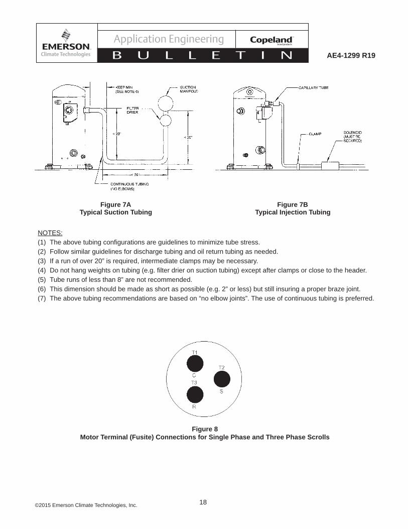
Tubing Considerations – Proper tube design must be taken into consideration when designing the tubing connecting the scroll to the remaining system. The tubing should provide enough “fl exibility” to allow normal starting and stopping of the compressor without exerting excessive stress on the tube joints. In addition, it is desirable to design tubing with a natural frequency different from the normal running frequency of the compressor. Failure to do this can result in tube resonance and unacceptable tubing life. Figures 7A and 7B are examples of acceptable tubing confi gurations.
pressure setting is too close, this will increase the possibility of short cycling.
3. Type of Low-pressure control can have an effect on cycling. The encapsulated non-adjustable type is more susceptible to causing excessive cycling due to tolerances.
4. If short cycling cannot be avoided, using a 3-minute time delay will limit the cycling of the compressor to an acceptable level.
IPR ValveRefrigeration scroll compressors (up to 9 HP size) have internal pressure relief valves which open at a discharge to suction differential pressure of 375 to 450 psi. This action will trip the motor protector and remove the motor from the line.
Motor ProtectionConventional inherent internal line break motor protection is provided.
Compressor Oil ChargeSee Table 6 for the proper fi eld oil recharge values.
The oil level of scroll compressors should be adjusted to the mid-point of the sight glass.
Oil Management for Rack ApplicationsCopeland™ refrigeration scroll compressors may be used on multiple compressor parallel rack applications. This requires the use of an oil management system to maintain proper oil level in each compressor crankcase. The sight glass connection supplied can accommodate the mounting of the oil control devices.
Unlike semi-hermetic compressors, scroll compressors do not have an oil pump with accompanying oil pressure safety controls. Therefore, an external oil level control is required.
The OMB Oil Level Management Control combines the functions of level control and timed compressor shut-off should the level not come back to normal within a set period of time. This device has been found to provide excellent performance in fi eld tests on scroll compressors and is recommended for parallel system applications.
Immediately after system start-up the oil reservoir level will fl uctuate until equilibrium is reached. It is advisable to monitor the oil level during this time to assure suffi cient oil is available. This will prevent unnecessary trips of the oil control system.
8©2015 Emerson Climate Technologies, Inc.
AE4-1299 R19
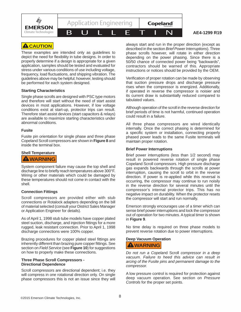
always start and run in the proper direction (except as described in the section Brief Power Interruptions). Three phase scrolls however, will rotate in either direction depending on the power phasing. Since there is a 50/50 chance of connected power being “backwards”, contractors should be warned of this. Appropriate instructions or notices should be provided by the OEM.
Verifi cation of proper rotation can be made by observing that suction pressure drops and discharge pressure rises when the compressor is energized. Additionally, if operated in reverse the compressor is noisier and its current draw is substantially reduced compared to tabulated values.
Although operation of the scroll in the reverse direction for brief periods of time is not harmful, continued operation could result in a failure.
All three phase compressors are wired identically internally. Once the correct phasing is determined for a specifi c system or installation, connecting properly phased power leads to the same Fusite terminals will maintain proper rotation.
Brief Power Interruptions Brief power interruptions (less than 1/2 second) may result in powered reverse rotation of single phase Copeland Scroll compressors. High pressure discharge gas expands backwards through the scrolls at power interruption, causing the scroll to orbit in the reverse direction. If power is re-applied while this reversal is occurring, the compressor may continue to run noisily in the reverse direction for several minutes until the compressor’s internal protector trips. This has no negative impact on durability. When the protector resets the compressor will start and run normally.
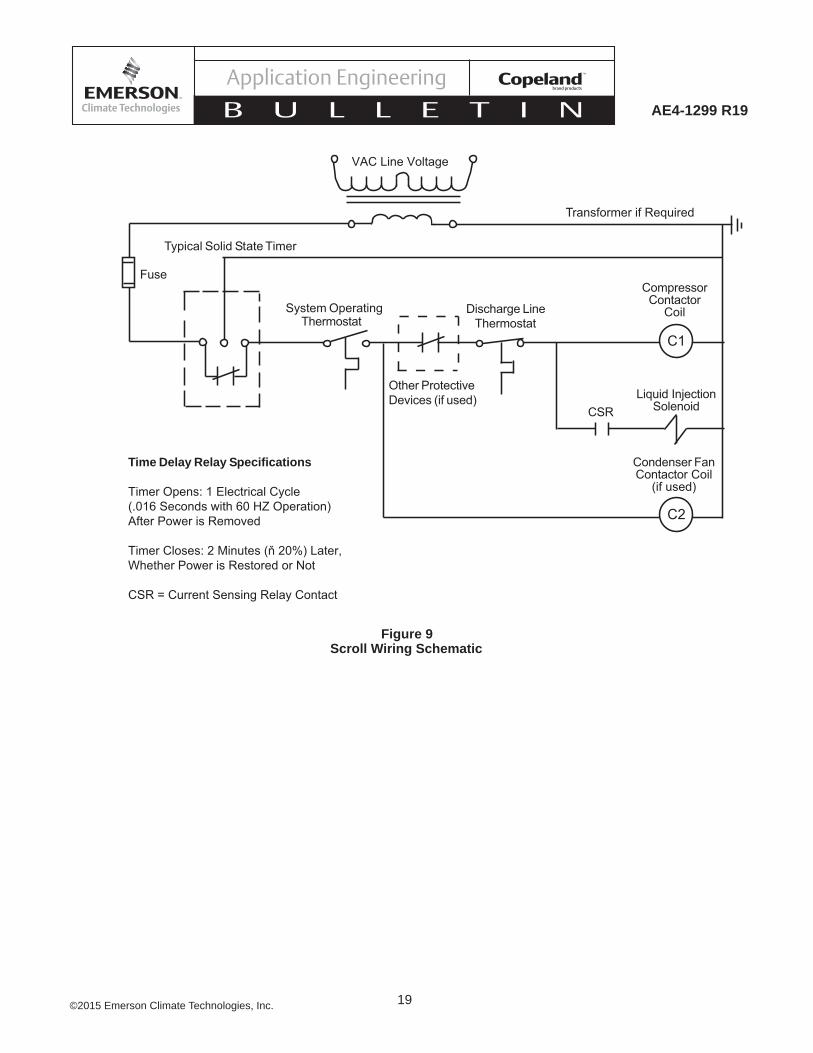
Emerson strongly encourages use of a timer which can sense brief power interruptions and lock the compressor out of operation for two minutes. A typical timer is shown in Figure 9.
No time delay is required on three phase models to prevent reverse rotation due to power interruptions.
Deep Vacuum OperationWARNING
Do not run a Copeland Scroll compressor in a deep vacuum. Failure to heed this advice can result in arcing of the Fusite pins and permanent damage to the compressor.
A low pressure control is required for protection against deep vacuum operation. See section on Pressure Controls for the proper set points.
CAUTIONThese examples are intended only as guidelines to depict the need for fl exibility in tube designs. In order to properly determine if a design is appropriate for a given application, samples should be tested and evaluated for stress under various conditions of use including voltage, frequency, load fl uctuations, and shipping vibration. The guidelines above may be helpful; however, testing should be performed for each system designed.
Starting CharacteristicsSingle phase scrolls are designed with PSC type motors and therefore will start without the need of start assist devices in most applications. However, if low voltage conditions exist at start-up, protector trips can result. Therefore start assist devices (start capacitors & relays) are available to maximize starting characteristics under abnormal conditions.
FusiteFusite pin orientation for single phase and three phase Copeland Scroll compressors are shown in Figure 8 and inside the terminal box.
Shell TemperatureWARNING
System component failure may cause the top shell and discharge line to briefl y reach temperatures above 300°F. Wiring or other materials which could be damaged by these temperatures should not come in contact with the shell.
Connection FittingsScroll compressors are provided either with stub connections or Rotalock adapters depending on the bill of material selected (consult your District Sales Manager or Application Engineer for details).
As of April 1, 1998 stub tube models have copper plated steel suction, discharge, and injection fi ttings for a more rugged, leak resistant connection. Prior to April 1, 1998 discharge connections were 100% copper.
Brazing procedures for copper plated steel fi ttings are inherently different than brazing pure copper fi ttings. See section on Field Service (see Figure 10) for suggestions on how to properly make these connections.
Three Phase Scroll Compressors -Directional DependenceScroll compressors are directional dependent; i.e. they will compress in one rotational direction only. On single phase compressors this is not an issue since they will
9©2015 Emerson Climate Technologies, Inc.
AE4-1299 R19
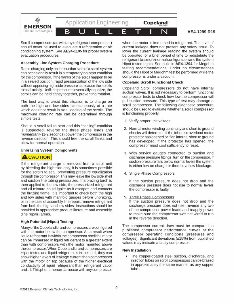
when the motor is immersed in refrigerant. The level of current leakage does not present any safety issue. To lower the current leakage reading the system should be operated for a brief period of time to redistribute the refrigerant to a more normal confi guration and the system Hipot tested again. See bulletin AE4-1294 for Megohm testing recommendations. Under no circumstances should the Hipot or Megohm test be performed while the compressor is under a vacuum.Copeland Scroll Functional CheckCopeland Scroll compressors do not have internal suction valves. It is not necessary to perform functional compressor tests to check how low the compressor will pull suction pressure. This type of test may damage a scroll compressor. The following diagnostic procedure should be used to evaluate whether a scroll compressor is functioning properly.
1. Verify proper unit voltage.
2. Normal motor winding continuity and short to ground checks will determine if the inherent overload motor protector has opened or if an internal short to ground has developed. If the protector has opened, the compressor must cool suffi ciently to reset.
3. With service gauges connected to suction and discharge pressure fi ttings, turn on the compressor. If suction pressure falls below normal levels the system is either low on charge or there is a fl ow blockage.
4. Single Phase Compressors
If the suction pressure does not drop and the discharge pressure does not rise to normal levels the compressor is faulty.
5. Three Phase CompressorsIf the suction pressure does not drop and the discharge pressure does not rise, reverse any two of the compressor power leads and reapply power to make sure the compressor was not wired to run in the reverse direction.
The compressor current draw must be compared to published compressor performance curves at the compressor operating conditions (pressures and voltages). Signifi cant deviations (±15%) from published values may indicate a faulty compressor.
New Installation• The copper-coated steel suction, discharge, and
injection tubes on scroll compressors can be brazed in approximately the same manner as any copper tube.
Scroll compressors (as with any refrigerant compressor) should never be used to evacuate a refrigeration or air conditioning system. See AE24-1105 for proper system evacuation procedures.
Assembly Line System Charging ProcedureRapid charging only on the suction side of a scroll system can occasionally result in a temporary no-start condition for the compressor. If the fl anks of the scroll happen to be in a sealed position, rapid pressurization of the low side without opposing high side pressure can cause the scrolls to seal axially. Until the pressures eventually equalize, the scrolls can be held tightly together, preventing rotation.
The best way to avoid this situation is to charge on both the high and low sides simultaneously at a rate which does not result in axial loading of the scrolls. The maximum charging rate can be determined through simple tests.
Should a scroll fail to start and this “sealing” condition is suspected, reverse the three phase leads and momentarily (1-2 seconds) power the compressor in the reverse direction. This should free the scroll fl anks and allow for normal operation.
Unbrazing System Components
CAUTIONIf the refrigerant charge is removed from a scroll unit by bleeding the high side only, it is sometimes possible for the scrolls to seal, preventing pressure equalization through the compressor. This may leave the low side shell and suction line tubing pressurized. If a brazing torch is then applied to the low side, the pressurized refrigerant and oil mixture could ignite as it escapes and contacts the brazing fl ame. It is important to check both the high and low sides with manifold gauges before unbrazing, or in the case of assembly line repair, remove refrigerant from both the high and low sides. Instructions should be provided in appropriate product literature and assembly (line repair) areas.
High Potential (Hipot) TestingMany of the Copeland brand compressors are confi gured with the motor below the compressor. As a result when liquid refrigerant is within the compressor shell the motor can be immersed in liquid refrigerant to a greater extent than with compressors with the motor mounted above the compressor. When Copeland brand compressors are Hipot tested and liquid refrigerant is in the shell, they can show higher levels of leakage current than compressors with the motor on top because of the higher electrical conductivity of liquid refrigerant than refrigerant vapor and oil. This phenomenon can occur with any compressor

10©2015 Emerson Climate Technologies, Inc.
AE4-1299 R19
Scroll Tube Brazing
• Recommended brazing material - Any Silfos material is recommended, preferably with a minimum of 5% silver. However, 0% silver is acceptable.
• Use of a dry nitrogen purge to eliminate possibility of carbon buildup on internal tube surfaces is recommended.
• Be sure process tube fi tting I.D. and process tube O.D. are clean prior to assembly.
• Apply heat in Area 1. As tube approaches brazing temperature, move torch fl ame to Area 2.
• Heat Area 2 until braze temperature is attained, moving torch up and down and rotating around tube as necessary to heat tube evenly. Add braze material to the joint while moving torch around circumference.
• After braze material fl ows around joint, move torch to heat Area 3. This will draw the braze material down into the joint. The time spent heating Area 3 should be minimal.
• As with any brazed joint, overheating may be detrimental to the fi nal result.
Field Service
To disconnect:
• Reclaim refrigerant from both the high and low side of the system. Cut tubing near compressor.
To reconnect:
• Recommended brazing materials; Silfos with minimum 5% silver or silver braze material with fl ux.
• Reinsert tube fi tting.
• Heat tube uniformly in Area 1, moving slowly to Area 2. When joint reaches brazing temperature, apply brazing material.
• Heat joint uniformly around the circumference to fl ow braze material completely around the joint.
• Slowly move torch in Area 3 to draw braze material into the joint.
Do not overheat joint.
11©2015 Emerson Climate Technologies, Inc.
AE4-1299 R19
° °
Evaporating Temperature
Con
dens
ing
Tem
pera
ture
R-134a ZF**K4E Envelope (Includes Liquid Injection)
Conditions: 65°F Return Gas; 0°F Subcooling, 95°F Ambient
Figure 1B
° °
Evaporating Temperature
Con
dens
ing
Tem
pera
ture
R-22 ZF**K4 Envelope (Includes Liquid Injection)
Conditions: 65°F Return Gas; 0°F Subcooling, 95°F Ambient
Figure 1A
R-404A/R-507/R-407A/R-407C/R-407F/R-448A/R-449AZF**K4E Envelope (Includes Liquid Injection)Conditions: 65°F Return Gas; 0°F Subcooling, 95°F Ambient
Figure 1CEvaporating Temperature
Con
dens
ing
Tem
pera
ture
Low CondensingTemperature
Region
°C °F
ZS**K4E Envelope (R-134A)
Figure 1D
Conditions: 65°F Return Gas; 0°F Subcooling, 95°F Ambient
ZS**K4E Envelope (R-404A/R-507)
Figure 1E
Conditions: 65°F Return Gas; 0°F Subcooling, 95°F Ambient
ZS**K4/K4E Envelope (R-22)
Figure 1F
Conditions: 65°F Return Gas; 0°F Subcooling, 95°F Ambient

12©2015 Emerson Climate Technologies, Inc.
AE4-1299 R19
Figure 3Copeland Scroll K4 Vapor Injection*
Figure 2Copeland Scroll K4 Liquid Injection*
* See catalog 1.401 for part information

13©2015 Emerson Climate Technologies, Inc.
AE4-1299 R19
Figure 4

14©2015 Emerson Climate Technologies, Inc.
AE4-1299 R19
FEATURES• Self contained unit with oil level sensor
and integral solenoid to manage oil level supply
• Hall-effect sensor for precise measurement of oil level
• Alarm and status indication by LEDs
• SPDT output contact for compressor shutdown or alarming
• Easy installation by sightglass replacement
• Adapters suitable for various types of compressors including conventional and scroll compressors
• Signal generated by gravity based fl oat-not prone to errors from foaming like optical sensors
• Sacrifi cial magnet for reliable operation
SAFETY INSTRUCTIONSWARNING: Before opening any system, make sure the pressure in the system is brought to and remains at atmospheric pressure. Failure to comply can result in personal injury and/or system damage.
1. Read installation instructions thoroughly. Failure to follow instructions may result in product failure, system damage, or personal injury.
2. Do not open system under pressure.
3. Ensure supply voltage is within specifi ed OMB limits.
4. Disconnect supply voltage from system/OMB before installation/service. Comply with local electrical regulations when wiring OMB.
5. Do not exceed maximum working pressure.
6. Keep temperature within nominal limits.
7. Work should be performed by qualifi ed service personnel or a licensed contractor
SPECIFICATIONS
Maximum Working Pressure:
500 psig
Solenoid MOPD: 350 psig
Supply Voltage: 24 VAC,50/60 Hz
Solenoid Coil:ASC2L
24 VAC,50/60 Hz
Current Consumption: 0.6A
Time Delay for Low Level Signal:
10 seconds
Time Delay After Setpoint Recovery:
5 seconds
Alarm Delay Time: (including alarm contact)
120 seconds
Alarm Switch:SPDTAlarm Contact Rating:
10A-125V,5A-250V
Refrigerant Compatibility:(not for use with fl ammablerefrigerants or ammonia)
HFC, HCFC, CFC
Refrigerant Temperature: -40°F TO 180°F
Storage and Ambient Temp.:
-40°F TO 120°F
Ambient Temp. (Housing): -40°F TO 120°F
Oil Supply fi tting: ¼ Male SAE
Compressor Adapter: See Table 1
Table 1Mounting Adapter Kit Applications
3/4"-NPTF Adapter Kit
ACA
Compressor Type Copeland Scroll
1.5 - 9 HP ZF, ZS, ZB
1 1/4" -12UNF Rotalock Adapter KitFlow controls part #:
P/N 066650 (KS30394-2)
Compressor TypeCopeland Scroll
1.5 - 9 HPZF, ZS, ZB
INSTALLATION INSTRUCTIONS1. Read installation instructions thoroughly.2. Assure that you have the appropriate
mounting adapter kit for the compressor. See Table 1. For semi-hermetic compressors see steps 1A through 5A below. For Copeland compressors using adapter kit ACA see steps 1B through 6B. For Copeland compressors using adapter kit ACB see steps 1C through 6C.
Kit ACA (Pipe Thread) for Copeland Scroll™ Compressors
1. Assure there is no pressure in the compressor crankcase and unscrew the ¾ pipe or the 1-1/4" rotalock connection thread attaching the original sight glass to the compressor. Take note of the original oil level since oil may be lost when the sight glass is removed. Tip the compressor to avoid oil loss if possible.
2. UOn compressors with the 3/4"-14 NPTF threaded fi tting, using PTFE tape as a sealant, thread the adapter into the compressor with the three hole fl ange installed on the adapter to capture in the assembly. The chamfered side of the threaded bolt holes should face outward. Torque the pipe thread to 30-40 ft.-lbs. Take care not to scratch the o-ring seal surface of the adapter. On compressors using the 1 1/4" rotalock connection remove the original gasket from the compressor assembly and replace with the new seal supplied with the adapter assembly. Torque the rotalock adapter assembly to 80-100 ft. lbs. Take care not to scratch the o-ring seal surface of the adapter.
3. Using the O-ring and bolts provided, install the control unit to the adapter fl ange. The top of the control unit must be perfectly horizontal with the oil inlet fi tting to the left. Torque the bolts to 120 in.-lbs.
4. Connect the oil supply line to the ¼ inch male fl are fi tting. A clean-able strainer is incorporated into the fi tting.
5. Make wiring connections in accordance with Figure 1. Important: The screw clamp style connector plugs used for the power supply and solenoid coil must be unplugged from the circuit board to gain access to the wire clamp screws. Use a small screwdriver to pry them outward.
6. Assure there is a proper oil level in the crankcase.
Figure 5 OMB Electronic Oil Level Management System Installation and Service Instructions

15©2015 Emerson Climate Technologies, Inc.
AE4-1299 R19

16©2015 Emerson Climate Technologies, Inc.
AE4-1299 R19
17©2015 Emerson Climate Technologies, Inc.
AE4-1299 R19
Figure 6B2-9 HP Copeland Scroll Condensing Unit Mounting
Kit 527-0116-00
2-9 HP Copeland Scroll Rack MountingFigure 6A
Kit 527-0157-00
18©2015 Emerson Climate Technologies, Inc.
AE4-1299 R19
Typical Suction Tubing Typical Injection TubingFigure 7A Figure 7B
NOTES:(1) The above tubing confi gurations are guidelines to minimize tube stress.(2) Follow similar guidelines for discharge tubing and oil return tubing as needed.(3) If a run of over 20” is required, intermediate clamps may be necessary.(4) Do not hang weights on tubing (e.g. fi lter drier on suction tubing) except after clamps or close to the header.(5) Tube runs of less than 8” are not recommended.(6) This dimension should be made as short as possible (e.g. 2” or less) but still insuring a proper braze joint.(7) The above tubing recommendations are based on “no elbow joints”. The use of continuous tubing is preferred.
Figure 8 Motor Terminal (Fusite) Connections for Single Phase and Three Phase Scrolls
19©2015 Emerson Climate Technologies, Inc.
AE4-1299 R19
Scroll Wiring SchematicFigure 9
Time Delay Relay Specifications
Timer Opens: 1 Electrical Cycle(.016 Seconds with 60 HZ Operation)After Power is Removed
Timer Closes: 2 Minutes (ň 20%) Later,Whether Power is Restored or Not
CSR = Current Sensing Relay Contact
Typical Solid State Timer
Fuse
Discharge LineThermostat
CompressorContactor
Coil
Condenser FanContactor Coil
(if used)
Other ProtectiveDevices (if used)
System OperatingThermostat
VAC Line Voltage
Transformer if Required
CSRLiquid Injection
Solenoid
C1
C2

20©2015 Emerson Climate Technologies, Inc.
AE4-1299 R19
ModelCap Tube
Emerson Kit NumberI.D.
(Inches)Length(Inches)
R-22ZF06K4 0.042 70 998-1583-00ZF08K4 0.042 70 998-1583-00ZF09K4 0.042 30 998-1583-03ZF11K4 0.042 30 998-1583-03ZF13K4 0.042 10 998-1583-05ZF15K4 0.042 5 998-1583-06ZF18K4 0.050 5 998-1586-00
R-404A/R-507/R-134AZF06K4E 0.042 70 998-1583-00ZF08K4E 0.042 70 998-1583-00ZF09K4E 0.042 70 998-1583-00ZF11K4E 0.042 50 998-1583-01ZF13K4E 0.042 40 998-1583-02ZF15K4E 0.042 30 998-1583-03ZF18K4E 0.042 20 998-1583-04
Table 2 Capillary Tubes For Liquid Injection
Models Part NumberZF 06, 08, 09, 11 ZS 15, 19, 21, 26 998-7026-00
ZF 13, 15, 18, 25, 28ZS 30, 38, 45 998-7024-00
Table 3BConduit Ready Heater Terminal Box Kits
ModelZF 06, 08, 09, 11, 13, 15, 18, 25, 28
ZS 15, 19, 21, 26, 30, 38, 45
Part Number Volts WattsLead
Length (in)
Grounding Wire
Length (in)018-0095-00 240 70 21.7 28.5018-0095-01 480 70 21.7 28.5018-0095-02 575 70 21.7 28.5018-0095-03 240 70 31.5 28.5018-0095-04 240 70 48.2 47.5018-0095-05 480 70 48.2 47.5018-0095-06 5750 70 48.2 47.5018-0095-07 120 70 48.2 47.5018-0095-08 400 70 48.2 47.5018-0095-09 277 70 21.7 28.5
Table 3A – Crankcase Heaters

21©2015 Emerson Climate Technologies, Inc.
AE4-1299 R19
Application Control Type
R-404A / R-507 R-22 R-407A / R-407F
R-448A / R-449A R-407C
Medium Temp (ZF)
LOW 17.1 PSIG Min. 10PSIG Min. 8 PSIG Min. 6 PSIG Min.HIGH 445 PSIG Max. 381 PSIG Max. 428 Max. 402 PSIG Max.
Medium Temp (ZS)
LOW 8 PSIG Min. 24 PSIG Min.N/A N/A
HIGH 445 PSIG Max. 381 PSIG Max.
Low Temp (ZF)
LOW 0 PSIG Min. 2 in. Hg Min. 4 in. Hg Min. 5 in. Hg Min.HIGH 400 PSIG Max. 335 PSIG Max. 375 PSIG Max. 352 PSIG Max
Table 5Low and High Pressure Control Settings for ZF*K4(E) & ZS*K4(E)
Table 4 Discharge Line Thermostat Kits
Table 6Oil Charges
Model Family Initial RechargeZF06K / ZS15K 44 40ZF08K / ZS19K 50 46ZF09K / ZS21K 49 45ZF11K / ZS26K 49 45ZF13K / ZS30K 64 60ZF15K / ZS38K 64 60ZF18K / ZS45K 64 60ZF25K 64 60ZF28K 64 60
Kit Number Discharge Line Diameter (in)
Lead Length
(in)Conduit
ConnectorAlarm
Contact Lead
Thermostat Number
Opening / Closing Temperatures °F
998-7022-01 3/8 36 Yes No 085-7022-07 221 191998-7022-03 3/8 36 Yes No 085-7022-08 221 191998-7022-02 1/2 36 Yes No 085-7022-06 220 170998-0548-00 1/2 36 No Yes 071-0634-00 220 170998-0540-00 1/2 12 No No 071-0632-00 220 170998-0541-00 1/2 12 No Yes 071-0633-00 220 170998-0548-01 3/4 36 No Yes 071-0634-01 220 170998-7022-04 5/8 36 Yes No 085-7022-09 220 170998-7022-07 3/4 36 Yes No 085-7022-12 220 170998-7022-05 7/8 36 Yes No 085-7022-10 220 170
The contents of this publication are presented for informational purposes only and are not to be construed as warranties or guarantees, express or implied, regarding the products or services described herein or their use or applicability. Emerson Climate Technologies, Inc. and/or its affi liates (collectively "Emerson"), as applicable, reserve the right to modify the design or specifi cations of such products at any time without notice. Emerson does not assume responsibility for the selection, use or maintenance of any product. Responsibility for proper selection, use and maintenance of any Emerson product remains solely with the purchaser or end user.