Embed Size (px)
Citation preview

U.S. Department of Transportation Federal Aviation Administration
Advisory Circular
Subject: Guidance for Parts Manufacturer Approval of Turbine Engine and Auxiliary Power Unit Parts under Test and Computation
Date: 8/19/09 Initiated by: ANE-110
AC No: 33-8
1. Purpose. a. This advisory circular (AC) provides guidance for developing substantiation data to support the design approval of critical and complex turbine engine and auxiliary power unit (APU) parts produced under parts manufacturer approval (PMA). This guidance is for the comparative test and analysis method used to show compliance to the airworthiness requirements under test and computation, per § 21.303 of Title 14 of the Code of Federal Regulations (14 CFR). This method supports showing the engine or APU still complies with 14 CFR part 33 and Technical Standard Order (TSO) C77. b. Additionally, this AC provides information on developing a continued operational safety (COS) plan and part numbering for turbine engine parts. 2. Applicability.
a. This AC provides guidance to applicants requesting PMA for critical and complex turbine engine or APU parts. For the purpose of this AC, the term “engine” represents a turbine engine and an APU, and the term “part” represents a turbine engine part and an APU part. b. This guidance is neither mandatory nor regulatory in nature and does not constitute a regulation. It describes acceptable means, but not the only means, for demonstrating compliance with the applicable regulations. The FAA will consider other methods of demonstrating compliance that an applicant may elect to present. Terms such as “should,” “shall,” “may,” and “must” are used only in the sense of ensuring applicability of this particular method of compliance when the acceptable method of compliance in this document is used. While these guidelines are not mandatory, they are derived from extensive FAA and industry experience in determining compliance with the applicable regulations. On the other hand, if we become aware of circumstances that convince us that following this AC would not result in compliance with the applicable regulations, we will not be bound by the terms of this AC, and we may require additional substantiation as the basis for finding compliance.

AC 33-8 8/19/09
2
c. This document does not change, create any additional, authorize changes in, or permit deviations from, existing regulatory requirements. 3. Related References. Please check the FAA’s website at http://www.faa.gov/regulations_policies/ for the latest revision of the following documents. a. AC 21-9A, Manufacturers Reporting Failures, Malfunctions, or Defects; May 26, 1982. b. AC 21-1B, Production Certificates; May 10, 1976. c. AC 33.75-1A, Guidance Material for 14 CFR 33.75, Safety Analysis; September 26, 2007. d. AC 39-8, Continued Airworthiness Assessments of Powerplant and Auxiliary Power Unit Installations of Transport Category Airplanes; September 8, 2003. e. Order 8110.37D, Designated Engineering Representative (DER) Handbook; August 10, 2006. f. Order 8110.42C, Parts Manufacturer Approval Procedures; June 23, 2008. g. Order 8110.54, Instructions for Continued Airworthiness Responsibilities, Requirements, and Contents; July 1, 2005. h. Order 8120.2F, Production Approval and Certificate Management Procedures; January 30, 2009. i. Order 8150.1B, Technical Standard Order Program; May 12, 2002. 4. Background. a. PMA applicants can show compliance to the airworthiness requirements of the product, i.e., engine certification basis, on which their proposed PMA part is to be installed under test and computation through comparative or general test and analysis, or a combination of both. Applicants requesting PMA for engine parts typically propose comparative test and analysis as the basis for their design approval. b. When applicants elect to use this comparative test and analysis method to comply with part 33 or TSO C77, the applicant should demonstrate that the functional design of their proposed PMA part is at least equal to that of the original type design part. Applicants frequently use reverse engineering of the type design part to support this approval basis. Although reverse engineering may be adequate to duplicate and substantiate the functional design of a simple engine part, complex or critical engine part designs generally need more rigorous analyses and tests to show equivalency between the type design and the proposed PMA part design. Thus, the test and substantiation plan applicants submit as part of their data package to show compliance

AC 33-8 8/19/09
3
should reflect the criticality or complexity of their proposed PMA part design to ensure the part meets the airworthiness requirements of part 33 or the standards of TSO C77. c. The FAA is providing the following guidance to assist applicants in developing the substantiation for the design approval of their complex or critical PMA engine parts when using the comparative test and analysis method. 5. Part Criticality. The data supplied by applicants to substantiate that the part meets the requirements of part 33 or TSO C77 varies depending upon the criticality or complexity of the part. This AC uses part categorization as guidance to applicants for determining whether or not a part is critical or complex. a. Methods for categorizing parts. This AC categorizes parts based on their most severe potential failure effect using various methods for assessing malfunctions and failure modes. Appendix 1 of this AC provides a failure modes and effects assessment suitable for engines. AC 33.75-1A provides descriptions of other acceptable analytical techniques. b. Part Categories. The categories that this AC addresses are consistent with the previously established categories used in certificate management oversight, as defined by Order 8120.2. These categories cover potential engine failure effects. These categories are also consistent with AC 39-8, which identifies the relative risks of parts and components that could hazard an aircraft if they fail or malfunction, and are based on historic service data and safety assessments. The part categories are defined as follows: (1) Category 1. A product, i.e. engine, or part(s) thereof, whose failure could prevent continued safe flight and landing; resulting consequences could reduce safety margins, degrade performance, or cause loss of capability to conduct certain flight operations. A Category 1 part, for the purpose of this AC, meets the definition of a critical part defined in Order 8110.42. (a) We recommend applicants who are considering applying for a PMA of a Category 1 engine part meet with the project aircraft certification office (PACO) to discuss a test and substantiation plan. Early coordination of these projects will help the applicant identify the necessary technical considerations and airworthiness requirements for that part. (2) Category 2. An engine or part(s) thereof whose failure would not prevent continued safe flight and landing; resulting consequences may reduce the capability of the aircraft or the ability of the crew to cope with adverse operating conditions or subsequent failures. For the purpose of this AC, a Category 2 engine part is typically a complex part that may affect a critical part. (a) Together with industry, we developed sample templates as aids to identify technical elements and regulatory requirements generally considered when developing test and substantiation plans. These templates are not all inclusive; rather, they are for a limited number of typical Category 2 engine parts. They are included in Appendix 2 of this AC.

AC 33-8 8/19/09
4
(b) For Category 2 engine parts, we recommend applicants discuss any questions regarding the templates with the PACO. If a template is not available for a proposed PMA part, we suggest applicants consider developing a new template to identify technical considerations and regulatory requirements. We recommend applicants stay close to the template format provided to do this. We also recommend applicants review the new template with the PACO early in their project to determine if any additional data will be needed. (3) Category 3. An engine or part(s) thereof whose failure would have no effect on continued safe flight and landing of the aircraft. The only consequence would be partial or complete loss of engine thrust or power (and associated engine services). For single engine applications, consider changing part categorization to category 1 or 2 if complete loss of thrust could prevent continued safe flight and landing or reduce the ability of the crew to cope with adverse operating conditions or subsequent failures. c. Tables of Potential Failure Effects. The following tables provide potential failure effects for categories 1 and 2. We also listed some examples of parts whose malfunction or failure could result in one or more of the listed potential failure effects.

AC 33-8 8/19/09
5
Table 1. Category 1 Potential Failure Effects Part Examples (1) Non-containment of high-energy debris. (2) Concentration of toxic products in the engine bleed air intended for the cabin, and sufficient to incapacitate crew or passengers. (3) Significant thrust in the opposite direction to that commanded by the pilot. (4) Uncontrolled fire. (5) Failure of the engine mount system leading to inadvertent engine separation. (6) Release of the propeller by the engine, if applicable. (7) Complete inability to shut the engine down.
Life-limited parts. Main engine mounts, with no redundant load carrying features. High pressure vessels (for example, casings subject to compressor discharge pressure and combustor pressure). Containment structures. Fan blades. Fuel system shut-off. Primary structures (for example, structures that provide support and rigidity of the main engine backbone and for attachment of engine to airframe). Thrust reverser control component if thrust reverser control component is part of the engine type certificate (TC).

AC 33-8 8/19/09
6
Table 2. Category 2 Potential Failure Effects Part Examples (1) Controlled fires (that is, those brought under control by shutting down the engine or by onboard extinguishing systems). (2) Case burn-through where it can be shown there is no propagation to hazardous engine effects. (3) Release of low-energy parts where it can be shown there is no propagation to hazardous engine effects. (4) Vibration levels that result in crew discomfort. (5) Concentration of toxic products in the engine bleed air for the cabin sufficient to degrade crew performance. (6) Thrust in the opposite direction to that commanded by the pilot, below the level defined as hazardous. (7) Loss of integrity of the load path of the engine supporting system without actual engine separation. (8) Generation of thrust greater than maximum rated thrust. (9) Significant uncontrollable thrust oscillation. (10) Loss of protection such as loss of overspeed protection or loss of containment case capability. (11) Effect or influence on a Category 1 part.
Rotating parts that are not life-limited (for example, compressor and turbine airfoils). Accessory gearbox and internal components. Engine bearings. Spinners. Main engine mounts with redundant load carrying features. Static gas path parts (for example, vanes and seals). Control system actuators. Combustion liners. Fuel nozzles.
AC 33-8 8/19/09
7
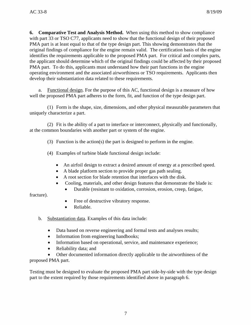
6. Comparative Test and Analysis Method. When using this method to show compliance with part 33 or TSO C77, applicants need to show that the functional design of their proposed PMA part is at least equal to that of the type design part. This showing demonstrates that the original findings of compliance for the engine remain valid. The certification basis of the engine identifies the requirements applicable to the proposed PMA part. For critical and complex parts, the applicant should determine which of the original findings could be affected by their proposed PMA part. To do this, applicants must understand how their part functions in the engine operating environment and the associated airworthiness or TSO requirements. Applicants then develop their substantiation data related to these requirements. a. Functional design. For the purpose of this AC, functional design is a measure of how well the proposed PMA part adheres to the form, fit, and function of the type design part. (1) Form is the shape, size, dimensions, and other physical measurable parameters that uniquely characterize a part. (2) Fit is the ability of a part to interface or interconnect, physically and functionally, at the common boundaries with another part or system of the engine. (3) Function is the action(s) the part is designed to perform in the engine. (4) Examples of turbine blade functional design include:
• An airfoil design to extract a desired amount of energy at a prescribed speed. • A blade platform section to provide proper gas path sealing. • A root section for blade retention that interfaces with the disk. • Cooling, materials, and other design features that demonstrate the blade is:
• Durable (resistant to oxidation, corrosion, erosion, creep, fatigue, fracture).
• Free of destructive vibratory response. • Reliable.
b. Substantiation data. Examples of this data include:
• Data based on reverse engineering and formal tests and analyses results; • Information from engineering handbooks; • Information based on operational, service, and maintenance experience; • Reliability data; and • Other documented information directly applicable to the airworthiness of the
proposed PMA part. Testing must be designed to evaluate the proposed PMA part side-by-side with the type design part to the extent required by those requirements identified above in paragraph 6.

AC 33-8 8/19/09
8
7. Reverse Engineering Considerations. Extracting the functional design of a critical or complex part through reverse engineering requires rigorous testing and analyses. This rigorous evaluation (test and analysis) is necessary to determine the dimensional, material, and processing characteristics needed to develop the proposed PMA part design. This part design consists of drawings and specifications, including a list of drawings and specifications needed to define the configuration and design features of the part. It also includes information on materials, dimensions, and processes necessary to define the structural strength of the part and airworthiness limitations, if required. a. Reverse engineering a critical or complex part design is far more extensive and difficult than creating a computer-aided-drawing or model of that part. Unintended differences can occur when developing the drawings this way. Applicants should consider a rigorous design and review process to minimize these differences. We recommend applicants use specifications such as American Society of Mechanical Engineers ASME Y14.5M Dimensioning and Tolerancing, or an equivalent specification, for data collection techniques. (1) Since applicants generally don’t know the type design part tolerances before starting a project, determining the measurement method to obtain the required accuracy is a necessary first step. Accuracy is defined as the maximum amount by which the measured result differs from the true value. A general rule of thumb is that measurement accuracy should be at most 10 percent of the expected tolerance. Experience plays a major role in understanding what types of tolerances are used on specific products and features. National standards provided by organizations such as the American Gear Manufacturer’s Association (AGMA) or the American Bearing Manufacturer’s Association (ABMA), or drawings of similar parts, are useful starting points but should not be used in lieu of actual measurement. Also, a feature’s surface finish can provide guidance for required measurement accuracy. (2) Examples of acceptable measurement accuracies are: (a) For a roller or ball bearing used in a gas turbine engine, precision measuring equipment capable of measuring to an accuracy of 0.00001 inch or better. (b) For a precision ground surface used as a land for a carbon seal, optical flats to get the required flatness. b. When reverse engineering, we recommend taking measurements from multiple type design samples to create the tolerance bands for the drawings and specifications of the proposed PMA part. These tolerance bands tend to be tighter than those of the type design, particularly if based on a limited sample size. A purely statistical method for determining the sample size may result in a sample size which is extensive but not practical. The drawing tolerances determined by reverse engineering for the proposed PMA part should not exceed the measured data (unless substantiated). Applicants should verify that their proposed PMA part can be manufactured to these tighter tolerances. If tighter tolerances cannot be achieved, then the applicant may either: (1) Analyze more type design parts to expand the reverse-engineered tolerances, change the drawing requirements, and support the manufacturing process; or

AC 33-8 8/19/09
9
(2) Use a more precise manufacturing method (for example, grinding versus milling) to bring the proposed manufactured part within tolerances. c. A reverse-engineered PMA part is intended to duplicate the form, fit, and function of the type design part it is planned to replace. Therefore, reverse engineering a part or an assembly is not limited to copying the physical type design part. Some aspects of the type design cannot be revealed through physical observation. For example, the outcome of certain manufacturing processes, such as heat treat and shot peening, can only be evaluated by destructive inspection techniques. Therefore, these types of manufacturing processes must be carefully controlled to ensure the produced PMA part is at least equal to the type design part throughout manufacture. Table 3 provides examples of manufacturing processes that may require control. For PMA parts that have controlled manufacturing processes, we recommend applicants provide their plans for validating these processes at the time of their PMA application. We refer to these plans as source substantiation plans.

AC 33-8 8/19/09
10
Table 3. Typical Controlled Manufacturing Processes
1. Abrasive finishing, for example, tumbling and machining 2. Anodizing and hardcoat 3. Brazing 4. Case hardening (case carburizing) 5. Casting processes 6. Chemical cleaning 7. Cold working, for example, bending, straightening, and hammering 8. Conventional machining (feeds, speeds, and tool wear) 9. Diffusion coating (aluminizing) 10. Dry film lube (application of) 11. Electron beam (EB) weld 12. Electro discharge machining (EDM) 13. Forging processes 14. Grit and abrasive blasting (wet or dry) 15. Heat treatment 16. Hot forming 17. Laser drilling (cutting and marking) 18. Plating 19. Rust inhibiting 20. Shot peening 21. Spot and seam welding 22. Spark grinding 23. Titanium chemical cleaning 24. Tungsten inert gas (TIG) welding 25. Tooling design, for example, dies and grip fixtures 26. Vapor degreasing 27. Electro chemical machining (ECM) 28. Composite material manufacturing processes 29. Media (Mass) finish 30. Plasma spraying 31. Titanium welding 32. Bi-metallic welding 33. Electrochemical marking 34. Laser shock peening 35. Elastomeric material processes, for example, curing and mixing 36. Ultrasonic and eddy current inspection (ECI) 37. Inertia welding 38. Translational friction welding 39. Friction stir welding 40. Hole drilling of high length over diameter (L/D) holes 41. Broaching 42. Material removal in general for rotating parts

AC 33-8 8/19/09
11
d. The part design extracted through reverse engineering data, along with other factors such as service experience, may form the basis on which improvements to features or characteristics are introduced. However, intentional deviation from the type design of critical and complex parts can raise concerns regarding configuration management issues, unintended consequences of the design change, and applicability of the existing instructions for continued airworthiness (ICA). Therefore, applicants should consider introducing a change to their proposed PMA part design only after completing a detailed examination and design evaluation to determine if the change constitutes a major design change per § 21.93. Applicants must clearly identify and justify through engineering evaluation all intentional changes to the proposed PMA part design with the ACO engineer(s) reviewing the design approval. (1) Configuration management issues can occur because the TC holder can make changes to their part or assembly designs without considering alternate PMA-approved configurations. For instance, if a PMA part adds a disassembly aid feature, such as a tab, and subsequently the TC holder makes a design change to the mating part that creates an interference with the tab on the PMA part, then the PMA part would not be upwardly compatible with the TC holder’s design change. (2) Unintended consequences may also occur when applicants make changes to their proposed PMA part design. For example, if the PMA holder alters their turbine blade design to make the dovetail stronger, this could change the “weak link” in the system from the blade to the disk post. Consequently, a disk post failure of the PMA part could result in the release of at least two blades and a disk post instead of a single blade, which was the type design intent. Thus, applicants must have a thorough understanding of the relationship between their proposed changes and the assembly in which their part is installed. (3) Applicants must account for any differences between their proposed PMA part and the type design part when assessing the applicability of the existing ICA, including repair processes. When the proposed PMA part can be installed in multiple engine models, we recommend that applicants consider the most limiting operating or installation conditions, or both, such as:
• Installation applications, such as single engine versus multi-engine aircraft. • Engines approved for Extended Operations (ETOPS). • Recommended operating limitations, such as
Time Between Overhaul, Thrust and power ratings, and Redlines.
e. An outline of a reverse engineering design process for complex parts is provided in Appendix 3.

AC 33-8 8/19/09
12
8. Continued Operational Safety. PMA holders must support the continued operational safety of their designs. We recommend applicants develop a COS plan to do this. To establish an effective COS plan, applicants should have the ability to assess design, manufacturing, and maintenance issues related to the operation of the engine on which their proposed PMA part is installed. a. A COS plan generally includes a suitable management plan that includes continuous assessment of the part’s performance in service relative to the applicant’s design assumptions. If a failure, malfunction, or defect in service is identified, the PMA holder must report it as required by § 21.3. b. A COS plan also includes appropriate methods and resources to identify the cause of a failure, malfunction or in-service defect, develop corrective actions, and implement those actions in a timely manner. Applicants should also validate that the corrective actions restore the engine to an acceptable level of safety. c. Appendix 4 of this AC provides additional information on how to develop a successful COS plan. If applicants elect to submit a COS plan, they should submit their plan during the design approval phase of the PMA process. 9. Part Numbering. When applicants assign a part number (P/N) to their PMA part, we recommend they use a suffix or prefix of at least 2 letters. The use of a single letter prefix or suffix to the type design part number may result in confusion between the PMA and type design parts. Engine TC holder part numbering practices often employ a single letter prefix or suffix. For example, P/Ns 123456A and 123456B, or A123456 and B123456, designate certain changes to the type design part. Since applicants generally do not have complete knowledge of the type design part number evolution, they should use care when selecting the proposed PMA part number.
Francis A. Favara Manager, Engine and Propeller Directorate Aircraft Certification Service
AC 33-8 8/19/09 Appendix 1
13
APPENDIX 1. FAILURE MODES AND EFFECTS ASSESSMENT
1. A failure modes and effects assessment is a qualitative process, independent of failure rates and probabilities, by which each failure mode of a part in the engine system is analyzed. Some top-level functions typically considered in an engine failure modes and effects assessment are:
• Maintaining structural integrity, including allowed overspeed and overtemperature exceedances;
• Providing thrust or power; • Operating in inclement weather; • Providing customer bleed, power extraction, or both; and • Meeting fuel consumption, exhaust gas temperature, vibration, emission or noise limits.
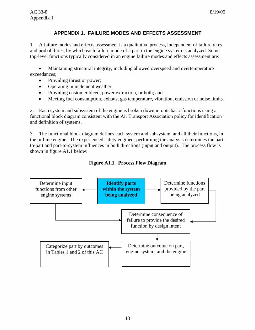
2. Each system and subsystem of the engine is broken down into its basic functions using a functional block diagram consistent with the Air Transport Association policy for identification and definition of systems. 3. The functional block diagram defines each system and subsystem, and all their functions, in the turbine engine. The experienced safety engineer performing the analysis determines the part-to-part and part-to-system influences in both directions (input and output). The process flow is shown in figure A1.1 below:
Figure A1.1. Process Flow Diagram
Determine input functions from other
engine systems
Identify parts within the system
being analyzed
Determine functions provided by the part
being analyzed
Determine consequence of failure to provide the desired
function by design intent
Determine outcome on part, engine system, and the engine
Categorize part by outcomes in Tables 1 and 2 of this AC

AC 33-8 8/19/09 Appendix 1
14
4. The part categorization process is built around the fundamental understanding of the part function and its potential effects on physically or functionally mating parts or both. The fundamental premise in the categorization process, and in the physical operation and function of the turbine engine, is system interactions. a. System interactions are influences a part, or a set of parts, can have on the turbine engine, propulsion system, or aircraft through form, fit, or function. These influences may extend beyond the component being classified, may be direct or indirect, and may develop immediately or over time. Characteristics of these influences include:
(1) Direct influences, which are form and fit. These influences are based on physical contact or interface clearances between adjacent parts. (2) Indirect influences, which are functional in nature. These influences are not based on physical contact, but may be aerodynamic, thermal, or vibratory.
5. The interactions where the consequence of failure is the furthest from the cause are the most difficult to identify. Many fundamental relationships in part interactions and subsequent system effects exist. Figure A1.2 below provides four examples.
Figure A1.2. Part Interaction Considerations
Part Interaction Considerations•Fluid interactions
• Air, fuel, oil•Direct interactions
• Mechanical loading
• Aero loading• Contact/wear• Chemical
•Indirect interactions• Vibration• Acoustical• Primary air• Secondary air• Control
system• Structural
dynamics• Sensor
systems
Stage 1 HPT Nozzle
1
2
3
4
Effective area/flow
HPC press. ratio
Stall margin consumption
Stall at limiting condition
Fuel Pump Impeller
Fuel flow schedule
Fuel to Combustor
Starting characteristic
Altitude re-light capability
Stage 2 HPT Nozzle
Cooling flow to rotor
Purge flow level
Hot gas ingestion
Critical part temperature &
life
Rotor BladeLoads and
moments on disk
Local dovetail loading
Dovetail or slot bottom life
LLP life impact
Indirect Effect
Indirect Effect
Time Relationship
Direct Effect

AC 33-8 8/19/09 Appendix 2
15
APPENDIX 2. TEMPLATES
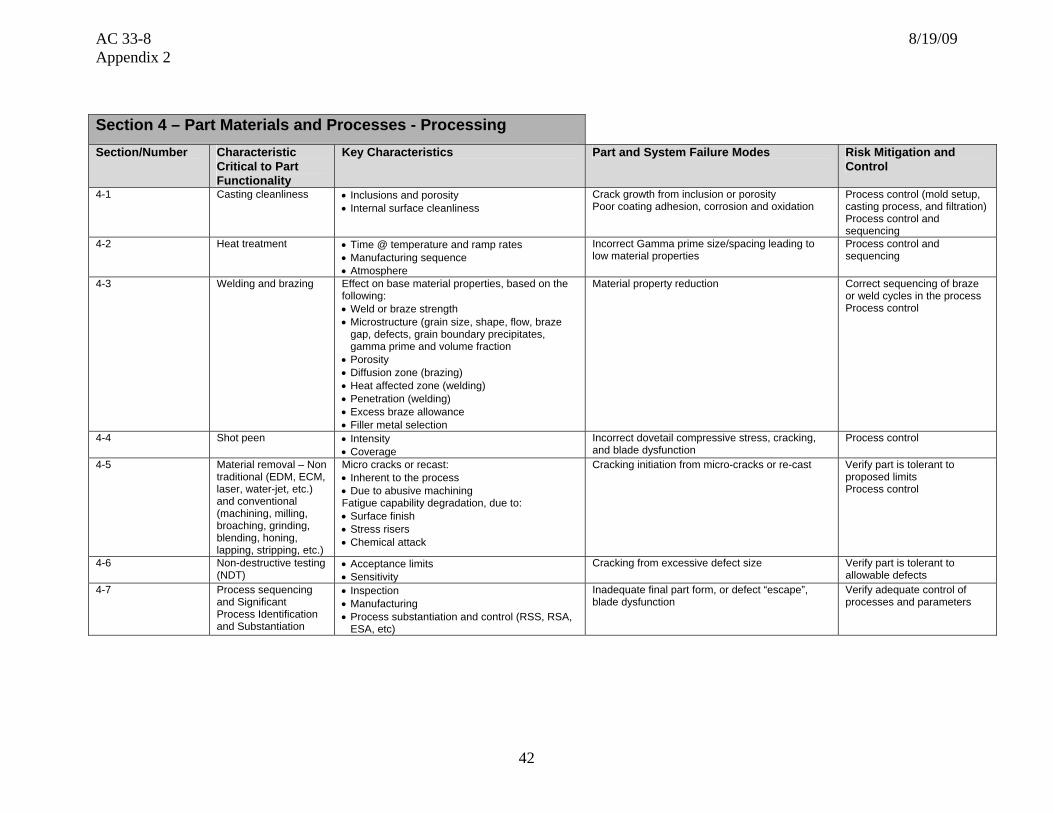
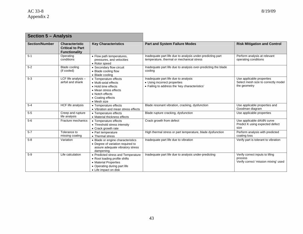
1. This appendix provides 17 templates, listed in Table A2-1 below. The FAA selected them based on what we found applicants were typically submitting for complex turbine engine part PMA approval. These templates will aid applicants in identifying the technical elements and regulatory requirements they should consider when developing their test and substantiation plans. Applicants must ensure that any additional technical criteria or regulatory requirements are met for their specific proposed PMA part. Each template is subdivided into the following sections: a. Section 1 - Part functional capability, which is the action the part is designed to perform in the engine. b. Section 2 - Part shape, size, dimensions, and other physical, measurable parameters; interconnectivity with an engine integral part or system; or both. c. Section 3 – Part materials and processes – properties. d. Section 4 – Part materials and processes – processing. e. Section 5 - Applicable analyses. f. Section 6 - Applicable testing. g. Section 7 - Applicable regulatory requirements.
2. Sections 1 through 5 are divided into the following five columns: a. Column 1 is the section number. b. Columns 2 and 3 identify part characteristics to be evaluated to support the functional design intent of the type design part. c. Column 4 identifies typical areas applicants should evaluate for potential part and system failure modes. d. Column 5 is used to identify a combination of actions and criteria for risk mitigation and control when a corresponding failure mode is identified in column 4.
3. Section 7 of the templates identifies the part 33 (Amendments 1-20 inclusive) airworthiness requirements applicable to turbine engines. However, not all engine certification bases include the same requirements. 4. If a template is not available for a particular part, the applicant can create or modify another as necessary. For example, although templates specific to APU parts are not provided, the

AC 33-8 8/19/09 Appendix 2
16
applicant may use the templates for similar APU parts and revise the regulatory section to reflect the requirements of TSO C77.
Table A2-1. Available Templates
Template Number
Part Name
1 O-Rings 2 Embedded elastomer seals 3 Combustor 4 Low pressure turbine blade 5 Turbine vane cooled 6 Turbine vane un-cooled 7 Shaft 8 Roller bearing 9 Ball bearing 10 Gear 11 Compressor vane 12 Compressor blade 13 Static air seal 14 Variable stator vane lever arms 15 Bushings 16 Turbine blade cooled 17 Fuel filter

AC 33-8 8/19/09 Appendix 2
17
Template #1: O-Rings
This template deals with non-standard seals which are typically procured under a TC holder part number. If the part is listed as a standard part and can be procured commercially these requirements do not apply.
Nomenclature for Generic Component Features (all features may not be applicable)
Inner Diameter
Outer Diameter
Width
Cross-Section Shape May Vary
Mold Line/Flash

AC 33-8 8/19/09 Appendix 2
18
Section 1 – Part Functional capability, i.e., the action(s) that the part is designed to perform in the product Section/Number
Characteristic Critical to Part Functionality
Key Characteristics Part and System Failure Modes Risk Mitigation and Control
1-1 Static Size • Physical dimension • Dimensionally within limits • Dimensional process control
1-2 Material • Actual material used in part • Base material certifications • Verify certificates 1-3 Temperature limits • Maximum and minimum temperatures • Recommended limits by manufacturer • Verify capability exceeds
expected duty cycle 1-4 Chemical resistance • Compatibility with TC holder approved fluids in
applicable system. • Recommended limits by manufacturer • Verify capability exceeds
expected duty cycle • Verify chemical
compatibility with TC holder approved fluids.
Section 2 – Part Shape, size, dimensions and other physical measurable parameters, and interconnectivity with an engine integral part/system Section/Number
Characteristic Critical to Part Functionality
Key Characteristics Part and System Failure Modes Risk Mitigation and Control
2-1 Boundary dimensions
• Inside diameter • Outside diameter • Cross sectional size
• Installation into assembly
• Dimensional process control and inspection
2-2 Surface finish • Actual surface conditions • Ability to perform sealing function • Dimensional process control
2-3 Fit-up dimensions • Design compression/expansion • set/spring back
• Ensure compression is within the allowable range • Dimensional process control and inspection
2-4 Tolerance • Variance-Fluctuations in measurements
• Mechanical/Functional, failure due to variation from nominal
• Verify part is tolerant to variation
• Control of manufacturing and inspection processes

AC 33-8 8/19/09 Appendix 2
19
Section 3 – Part Materials and Processes – Properties Section/Number
Characteristic Critical to Part Functionality
Key Characteristics Part and System Failure Modes Risk Mitigation and Control
3-1 Chemistry • Major elements - % Variation • Impurities
• Poor mechanical or environmental resistance properties • Material selection • Process control
3-2 Physical properties • Density • Coefficient of thermal expansion • Melting Point
• Consistent properties within operating parameters • Material selection • Process control
3-3 Mechanical properties
• Modulus • Hardness/Durometer hardness
• Low material properties
• Adequate material properties • Operational effects accounted for
3-4 Environmental resistance
• Oxidation • Temperature range • Corrosion • Chemical resistance • Age related material property change
• Physical deterioration from Oxidation/Corrosion/chemical attack
• Property reduction due to extreme temperatures
• Verify adequate environmental properties
Section 4 – Part Materials and Processes - Processing Section/Number Characteristic
Critical to Part Functionality
Key Characteristics Part and System Failure Modes Risk Mitigation and Control
4-1 Raw material processing • Purity
• Inadequate material properties • Process control (melt control, cleanliness)
• Process control and sequencing
4-2 Surface treatment • Proper form and texture • Improper thickness and excess flash • Process control 4-3 Process sequencing and
Significant Process Identification and Substantiation
• Inspection • Manufacturing • Process Substantiation and Control
(RSS,RSA,ESA, etc)
• Inadequate final part form, or defect “escape” • Verify adequate control of processes and parameters
Section 5 – Analysis Section/Number Characteristic
Critical to Part Functionality
Key Characteristics Part and System Failure Modes Risk Mitigation and Control
5-1 Operating conditions
• Temperatures • Sealing ability • Proper contact pressures
• Inadequate part life due to analysis under-predicting part temperature, mechanical stress, chemical resistance
• Perform analysis at relevant operating conditions
5-2 Variation • Engine operation characteristics • Inadequate part function due to variation • Verify part is tolerant to variation

AC 33-8 8/19/09 Appendix 2
20
Section 6 – Testing
Section/Number Characteristic Critical to Part Functionality
Key Characteristics Part and System Failure Modes
Risk Mitigation and Control
6-1 Durability • Engine vibration response • Leakage
• Excessive leakage • Excessive Vibration
• Perform adequate component and/or engine testing
6-2 Operability and performance
• Vibration signature • Abnormal wear • Environmental testing to hot and cold limitations for the
engine. Thermal conditions at the “O” ring seal installed location
• Durability/replacement interval(s)/shelf life, etc, if applicable?
• Excessive leakage • Difficult to
disassemble after operation
• Engine testing
Section 7 – Potential Impact on Regulatory Requirements
Note: The regulatory requirements identified below, which are inclusive up to Amendment 20 of 14 CFR part 33, are intended as a guide to applicants when determining the applicable regulations to which they must show compliance. Those requirements listed as “Could be affected” highlight the regulations whose compliance findings are typically affected by the component or part that this template is addressing. This guide is not all-inclusive and the applicant remains responsible for identifying the certification basis of the product on which their PMA part is to be installed.
Applicable 14 CFR Part 33 Regulatory
Requirements Comments
Subpart A – General
1. 33.4 Instructions for Continued Airworthiness Could be affected ICAs including on-wing inspection requirements and on-wing limits for leakage
2. 33.5 Instruction manual for installing and operating the engine
3. 33.7 Engine ratings and operating limitations
4. 33.8 Selection of engine power and thrust ratings

AC 33-8 8/19/09 Appendix 2
21
Subpart B – Design and Construction; General
5. 33.14 Start-stop cyclic stress (low cycle fatigue)
6. 33.15 Materials Could be affected
7. 33.17 Fire prevention Could be affected No fluid leakage
8. 33.19 Durability Could be affected
9. 33.21 Engine cooling
10. 33.23 Engine mounting attachments and structure
11. 33.25 Accessory attachments
12. 33.27 Turbine, compressor, fan, and turbo-supercharger rotors
13. 33.28 Electrical and electronic control systems
14. 33.29 Instrumentation connection
Subpart E – Design and Construction;
Turbine Aircraft Engines
15. 33.62 Stress analysis
16. 33.63 Vibration Could be affected
17. 33.65 Surge and stall characteristics
18. 33.66 Bleed air systems
19. 33.67 Fuel system Could be affected Leakage limits
20. 33.68 Induction system icing (Operability aspects)
21. 33.69 Ignition system
22. 33.71 Lubrication system Could be affected Leakage limits
23. 33.72 Hydraulic actuating system Could be affected Leakage limits
24. 33.73 Power or thrust response
25. 33.74 Continued rotation
26. 33.75 Safety analysis

AC 33-8 8/19/09 Appendix 2
22
Subpart E – Design and Construction; Turbine Aircraft Engines
27. 33.76 Bird ingestion (Operability aspects of ingestion)
28. 33.77 Foreign object ingestion (Operability aspects of ingestion)
29. 33.78 Rain and hail ingestion
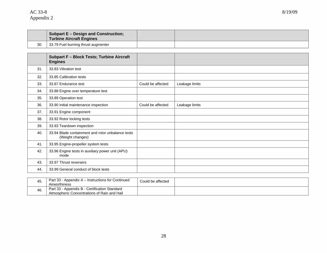
30. 33.79 Fuel burning thrust augmenter
Subpart F – Block Tests; Turbine Aircraft Engines
31. 33.83 Vibration test
32. 33.85 Calibration tests
33. 33.87 Endurance test Could be affected Leakage limits
34. 33.88 Engine over temperature test
35. 33.89 Operation test
36. 33.90 Initial maintenance inspection Could be affected Leakage limits
37. 33.91 Engine component tests
38. 33.92 Rotor locking tests
39. 33.93 Teardown inspection
40. 33.94 Blade containment and rotor unbalance tests (Weight changes)
41. 33.95 Engine-propeller system tests
42. 33.96 Engine tests in auxiliary power unit (APU) mode
43. 33.97 Thrust reversers
44. 33.99 General conduct of block tests
45. Part 33 - Appendix A – Instructions for Continued Airworthiness
Could be affected
46. Part 33 - Appendix B - Certification Standard Atmospheric Concentrations of Rain and Hail

AC 33-8 8/19/09 Appendix 2
23
Template #2: Embedded Elastomer Seals
This template deals with non-standard seals which are typically procured under an OEM part number. If the part is listed as a standard part and can be procured commercially, these requirements do not apply.
Nomenclature for Generic Component Features (all features may not be applicable)
Elastomeric Seal (Lip)
Puller Feature
Seal Diameter

AC 33-8 8/19/09 Appendix 2
24
Section 1 – Part Functional capability, i.e., the action(s) that the part is designed to perform in the product Section/Number
Characteristic Critical to Part Functionality
Key Characteristics Part and System Failure Modes Risk Mitigation and Control
1-1 Static size • Physical dimension of seal and carrier • Dimensions are within limits • Dimensional process control
1-2 Material • Actual material used in part • Base material certifications • Process control 1-3 Temperature limits • Maximum and minimum temperatures • Recommended limits by manufacturer • Verify capability exceeds
expected duty cycle 1-4 Chemical resistance • List of chemicals which the material is
compatible with
• Recommended limits by manufacturer • Surface dimensional process control
• Verify acceptable wear • Verify chemical
compatibility with approved engine fluids.
Section 2 – Part Shape, size, dimensions and other physical measurable parameters, and interconnectivity with an engine integral part/system Section/Number
Characteristic Critical to Part Functionality
Key Characteristics Part and System Failure Modes Risk Mitigation and Control
2-1 Boundary dimensions
• Hole locations • Inside contour • Outside contour • Cross sectional size of elastomer • Thickness of carrier
• Installation into assembly
• Dimensional process control and inspection
2-2 Surface finish • Actual surface conditions • Ability to perform sealing function • Dimensional process control
2-3 Fit-up dimensions • Design compression/expansion
• Ensure compression is within the allowable range • Dimensional process control and inspection
2-4 Tolerance • Variance-fluctuations in measurements • Parallelism of carrier
• Mechanical/Functional, failure due to variation from nominal
• Verify part is tolerant to variation
• Control of manufacturing and inspection processes

AC 33-8 8/19/09 Appendix 2
25
Section 3 – Part Materials and Processes – Properties Section/Number
Characteristic Critical to Part Functionality
Key Characteristics Part and System Failure Modes Risk Mitigation and Control
3-1 Chemistry • Major elements - % variation • Impurities
• Poor mechanical or environmental resistance properties • Material selection • Process control
3-2 Physical properties • Density • Coefficient of thermal expansion • Melting point
• Consistent properties within operating parameters • Material selection • Process control
3-3 Mechanical properties
• Modulus • Surface hardness
• Low material properties
• Adequate material properties • Operational effects accounted for
3-4 Environmental resistance
• Oxidation • Temperature range • Corrosion • Chemical resistance
• Physical deterioration from Oxidation/Corrosion/chemical attack
• Property reduction due to extreme temperatures
• Verify adequate environmental properties
• Verify chemical compatibility with approved engine fluids.
Section 4 – Part Materials and Processes - Processing Section/Number Characteristic
Critical to Part Functionality
Key Characteristics Part and System Failure Modes Risk Mitigation and Control
4-1 Raw material processing • Purity
• Inadequate material properties • Process control (melt control, cleanliness)
• Process control and sequencing
4-2 Surface treatment • Proper form and texture • Improper thickness and excess flash • Process control 4-3 Process sequencing and
Significant Process Identification and Substantiation
• Inspection • Manufacturing • Process Substantiation and Control
(RSS,RSA,ESA, etc)
• Inadequate final part form, or defect “escape” • Verify adequate control of processes and parameters
Section 5 – Analysis Section/Number Characteristic
Critical to Part Functionality
Key Characteristics Part and System Failure Modes Risk Mitigation and Control
5-1 Operating conditions
• Temperatures • Sealing ability • Proper contact pressures • Location of flange surfaces
• Inadequate part life due to analysis under-predicting part temperature, mechanical stress, chemical resistance
• Perform analysis at relevant operating conditions
5-2 Variation • Engine operation characteristics • Inadequate part function due to variation • Verify part is tolerant to variation

AC 33-8 8/19/09 Appendix 2
26
Section 6 – Testing
Section/Number Characteristic Critical to Part Functionality
Key Characteristics Part and System Failure Modes Risk Mitigation and Control
6-1 Durability • Engine vibration response • Leakage
• Excessive vibration • Excessive leakage
• Perform adequate component and/or engine testing
6-2 Operability and performance
• Vibration signature • Abnormal wear on affected parts
• Excessive vibration • Difficult to disassemble after operation
• Engine testing
Section 7 – Potential Impact on Regulatory Requirements
Note: The regulatory requirements identified below, which are inclusive up to Amendment 20 of 14 CFR part 33, are intended as a guide to applicants when determining the applicable regulations to which they must show compliance. Those requirements listed as “Could be affected” highlight the regulations whose compliance findings are typically affected by the component or part that this template is addressing. This guide is not all-inclusive and the applicant remains responsible for identifying the certification basis of the product on which their PMA part is to be installed.
Applicable 14 CFR Part 33 Regulatory
Requirements Comments
Subpart A – General
1. 33.4 Instructions for Continued Airworthiness Could be affected ICAs including on-wing inspection requirements and on-wing limits for leakage
2. 33.5 Instruction manual for installing and operating the engine
3. 33.7 Engine ratings and operating limitations Could be affected Adequate sealing required throughout engine operating envelope.
4. 33.8 Selection of engine power and thrust ratings
Subpart B – Design and Construction; General
5. 33.14 Start-stop cyclic stress (low cycle fatigue)
6. 33.15 Materials Could be affected
7. 33.17 Fire prevention Could be affected No fluid leakage
8. 33.19 Durability Could be affected

AC 33-8 8/19/09 Appendix 2
27
Subpart B – Design and Construction; General
9. 33.21 Engine Cooling
10. 33.23 Engine mounting attachments and structure
11. 33.25 Accessory attachments
12. 33.27 Turbine, compressor, fan, and turbo-supercharger rotors
13. 33.28 Electrical and electronic control systems
14. 33.29 Instrumentation connection
Subpart E – Design and Construction; Turbine Aircraft Engines
15. 33.62 Stress Analysis
16. 33.63 Vibration Could be affected
17. 33.65 Surge and stall characteristics
18. 33.66 Bleed air systems
19. 33.67 Fuel system Could be affected Leakage limits
20. 33.68 Induction system icing (Operability aspects)
21. 33.69 Ignition system
22. 33.71 Lubrication system Could be affected Leakage limits
23. 33.72 Hydraulic actuating system
24. 33.73 Power or thrust response
25. 33.74 Continued rotation
26. 33.75 Safety Analysis
27. 33.76 Bird Ingestion (Operability aspects of ingestion)
28. 33.77 Foreign object ingestion (Operability aspects of ingestion)
29. 33.78 Rain and hail ingestion
AC 33-8 8/19/09 Appendix 2
28
Subpart E – Design and Construction; Turbine Aircraft Engines
30. 33.79 Fuel burning thrust augmenter
Subpart F – Block Tests; Turbine Aircraft Engines
31. 33.83 Vibration test
32. 33.85 Calibration tests
33. 33.87 Endurance test Could be affected Leakage limits
34. 33.88 Engine over temperature test
35. 33.89 Operation test
36. 33.90 Initial maintenance inspection Could be affected Leakage limits
37. 33.91 Engine component
38. 33.92 Rotor locking tests
39. 33.93 Teardown inspection
40. 33.94 Blade containment and rotor unbalance tests (Weight changes)
41. 33.95 Engine-propeller system tests
42. 33.96 Engine tests in auxiliary power unit (APU) mode
43. 33.97 Thrust reversers
44. 33.99 General conduct of block tests
45. Part 33 - Appendix A – Instructions for Continued Airworthiness
Could be affected
46. Part 33 - Appendix B - Certification Standard Atmospheric Concentrations of Rain and Hail

AC 33-8 8/19/09 Appendix 2
29
Template #3: Combustor
Nomenclature for Generic Component Features
(all features may not be applicable)

AC 33-8 8/19/09 Appendix 2
30
Section 1 – Part Functional capability, i.e., the action(s) that the part is designed to perform in the product Section/Number
Characteristic Critical to Part Functionality
Key Characteristics Part and System Failure Modes Risk Mitigation and Control
1-1 Weight • As-cast surfaces • Machined surfaces
• Surface dimensional process control
1-2 Profile • Inner and outer wall contours • Nozzle area
• Operability effects • Emissions • Turbine airfoils durability
• Surface dimensional process control
1-3 Cooling/Dilution air utilization
• Total flow rate • Individual nozzle swirler/heatshield flow rate • ID/OD profile • Static pressure distribution
• Over-temperature/dysfunction • Emissions • Improper temperature profile: over-temperature/dysfunction
of downstream airfoils
• Cooling and dilution hole dimensional process control
• Burner rig testing
1-4 Structural strength • Combustor hood locating pins
• Static structure malfunction • Resonance avoidance at steady state operation with margin
1-5 Creep, LCF, fracture toughness, tensile overload capability
• Geometry • Cooling • Material mechanical/metallurgical/physical
properties
• Crack growth from LCF or Creep – Rupture
• Verify capability exceeds expected utilization
Section 2 – Part Shape, size, dimensions and other physical measurable parameters, and interconnectivity with an engine integral part/system Section/Number
Characteristic Critical to Part Functionality
Key Characteristics Part and System Failure Modes Risk Mitigation and Control
2-1 Inner and outer shells
• Profile and length • Axial location of forward and aft face • Functional fits at interfaces • Part/assembly locating features (axial, radial and
tangential) • Air sealing surfaces • Cooling and dilution holes
• Emissions effects • Combustor exit profile effects (pattern factor) • Lean blowout • Rumble or combustion Instability
• Dimensional process control and inspection
• Burner rig testing
2-2 Hood • Fuel nozzle location • Cooling hole location • Leading edge profile
• Durability • ID/OD airflow distribution • Lean blowout
• Dimensional process control • Burner rig testing
2-3 Fuel nozzle swirlers • Radial location • Cooling hole pattern • Size
• Durability
• Surface dimensional process control

AC 33-8 8/19/09 Appendix 2
31
Section 2 – Part Shape, size, dimensions and other physical measurable parameters, and interconnectivity with an engine integral part/system Section/Number
Characteristic Critical to Part Functionality
Key Characteristics Part and System Failure Modes Risk Mitigation and Control
2-4 Cast panels • Profile • Cooling pin/fin size and location
• Emissions • Durability
• Dimensional process control
2-5 Tolerance • Variance-Fluctuations in measurements • Measurement gauge repeatability and reliability
• Mechanical/Functional, failure due to vibration from nominal • Verify part is tolerant to variation
• Control of manufacturing and inspection processes
Section 3 – Part Materials and Processes – Properties Section/Number
Characteristic Critical to Part Functionality
Key Characteristics Part and System Failure Modes Risk Mitigation and Control
3-1 Chemistry • Major elements - % variation • Impurities
• Poor mechanical or environmental properties • Poor TBC adherence
• Material selection • Master heat and process control
3-2 Physical properties • Density • Coefficient of thermal expansion • Refractive Index (x-rays)
• Excessive weight • Excessive thermal stresses • Interference with surrounding hardware
Verify: • Acceptable weight • Acceptable stresses • Combustor “fit” in hot condition
3-3 Mechanical /metallurgical properties
• Modulus (vs. grain orientation) • Bare and coated: tensile (UTS, YS,
elongation, stress rupture, creep, LCF, HCF)
• Long term metallurgical stability
• Excessive strain-controlled stress • Undesirable natural frequency • Low material properties, dysfunction • Material capability consumed in operation
Verify: • Acceptable stresses and frequencies • Adequate material properties • Operational effects accounted for • Relevant properties are used
3-4 Cast structure • Grain Structure (size, shape, flow, boundaries, gamma prime size and volume fraction)
• Low angle boundaries • Directional properties • Hardness • Melting Point • Crack propagation rate
• Material property reduction due to excessive grain angle or low angle boundaries, cast panel dysfunction
• Verify that grain orientation or low angle boundaries are accounted for
• Process control and inspection
3-5 Environmental resistance
• Oxidation, corrosion, erosion, fretting resistance
• Elevated temperature (creep, diffusion, ageing, temp. gradients)
• FOD resistance
• Cracking from oxidation/corrosion pitting, dysfunction • Verify adequate environmental properties

AC 33-8 8/19/09 Appendix 2
32
Section 3 – Part Materials and Processes – Properties Section/Number
Characteristic Critical to Part Functionality
Key Characteristics Part and System Failure Modes Risk Mitigation and Control
3-6 Environmental coating
• Coverage and thickness • Long term stability • Oxidation and corrosion resistance
• LCF property reduction due to poor coating selection/requirements, panel cracking
• Cracking from oxidation/corrosion pitting
• Control of chemistry and application process
• Verify thermal-mechanical compatibility with base material
3-7 Thermal barrier coating
• Coating material composition and density • Thermal conductivity (coefficient of thermal
expansion) • Coverage and thickness uniformity • Coating and diffusion zone microstructure • Adhesion • Oxidation • Resistance to spalling, sintering and
erosion • Hardness • Residual Stress • Stripping requirements • Bonding (Interface Contamination) • Compatibility with base material/other
coatings
• High thermal stresses or part temperature, swirler and panel dysfunction
• Control of chemistry and application process
• Verify part is tolerant to missing TBC • No high TBC temperatures that
accelerate spalling
Section 4 – Part Materials and Processes - Processing Section/Number Characteristic
Critical to Part Functionality
Key Characteristics Part and System Failure Modes Risk Mitigation and Control
4-1 Casting cleanliness • Inclusions and porosity • Internal surface cleanliness
• Crack growth from inclusion or porosity • Poor coating adhesion, corrosion and oxidation
• Process control (mold setup, casting process, and filtration)
• Process control and sequencing
4-2 Heat treatment • Time @ temperature and ramp rates • Manufacturing sequence • Atmosphere
• Incorrect Gamma Prime size/spacing leading to low material properties
• Process control and sequencing

AC 33-8 8/19/09 Appendix 2
33
Section 4 – Part Materials and Processes - Processing Section/Number Characteristic
Critical to Part Functionality
Key Characteristics Part and System Failure Modes Risk Mitigation and Control
4-3 Welding and brazing Effect on base material properties, based on the following: • Weld or braze strength • Microstructure (grain size, shape, flow, braze
gap, defects, grain boundary precipitates, gamma prime and volume fraction
• Porosity • Diffusion zone (brazing) • Heat affected zone (welding) • Penetration (welding) • Excess braze allowance • Filler metal selection
• Material property reduction
• Correct sequencing of braze or weld cycles in the process
• Process control
4-4 Material removal – Non traditional (EDM, ECM, Laser, Water-Jet, etc.) and conventional (machining, milling, broaching, grinding, blending, honing, lapping, stripping, etc.)
Micro cracks or recast: • Inherent to the process • Due to abusive machining Fatigue capability degradation, due to: • Surface finish • Stress risers • Chemical attack
• Cracking initiation from micro-cracks or re-cast • Verify part is tolerant to proposed limits
• Process control
4-5 Non-destructive testing (NDT)
• Acceptance limits • Sensitivity
• Cracking from excessive defect size • Verify part is tolerant to allowable defects
4-6 Process sequencing and Significant Process Identification and Substantiation
• Inspection • Manufacturing • Process substantiation and control (RSS, RSA,
ESA, etc)
• Inadequate final part form, or defect “escape”, dysfunction
• Verify adequate control of processes and parameters
Section 5 – Analysis Section/Number Characteristic
Critical to Part Functionality
Key Characteristics Part and System Failure Modes Risk Mitigation and Control
5-1 Operating conditions
• Flow path temperatures, pressures, and velocities
• Nozzle area • Exit profile
• Compressor operability • Turbine airfoil durability
• Perform analysis at relevant operating conditions
5-2 Swirler cooling • Secondary flow circuit • Swirler cooling flow
• Inadequate part life due to analysis over-predicting the swirler cooling effectiveness

AC 33-8 8/19/09 Appendix 2
34
Section 5 – Analysis Section/Number Characteristic
Critical to Part Functionality
Key Characteristics Part and System Failure Modes Risk Mitigation and Control
5-3 LCF/TMF life analysis
• Temperature effects • Multi-axial effects • Hold time effects • Mean stress effects • Notch effects • Coating effects • Mesh size
Inadequate part life due to analysis • Using incorrect properties • Failing to address the ‘key characteristics’
• Use applicable properties • Select mesh size to correctly
model the geometry
5-4 HCF life analysis • Temperature effects • Vibration and mean stress effects
• Combustor resonant vibration, cracking, dysfunction • Use applicable properties and Goodman Diagram
5-5 Creep and rupture life analysis
• Temperature effects • Material thickness effects
• Combustor rupture cracking, dysfunction • Use applicable properties
5-6 Fracture mechanics • Temperature effects • Threshold stress intensity • Crack growth rate
• Crack growth from defect • Use applicable dA/dN curve • Predict K using expected defect
size 5-7 Tolerance to
missing TBC • Part temperature • Thermal stress
• High thermal stress or part temperature, dysfunction • Perform analysis with predicted TBC loss
Section 6 – Testing
Section/Number Characteristic Critical to Part Functionality
Key Characteristics
Part and System Failure Modes Risk Mitigation and Control
6-1 Durability • Fatigue • Corrosion (hot and
cold) • Erosion • Stress rupture • Tensile strength • Cooling Effectiveness
6-2 Over-temperature • Microstructure • Creep • Hot corrosion • Tensile strength
6-3 Emissions • Smoke, HC, CO, NoX

AC 33-8 8/19/09 Appendix 2
35
Section 7 – Potential Impact on Regulatory Requirements
Note: The regulatory requirements identified below, which are inclusive up to Amendment 20 of 14 CFR part 33, are intended as a guide to applicants when determining the applicable regulations to which they must show compliance. Those requirements listed as “Could be affected” highlight the regulations whose compliance findings are typically affected by the component or part that this template is addressing. This guide is not all-inclusive and the applicant remains responsible for identifying the certification basis of the product on which their PMA part is to be installed.
Applicable 14 CFR Part 33 Regulatory
Requirements Comments
Subpart A – General
1. 33.4 Instructions for Continued Airworthiness Could be affected ICAs including on-wing inspection requirements and on-wing limits
2. 33.5 Instruction manual for installing and operating the engine
3. 33.7 Engine ratings and operating limitations
4. 33.8 Selection of engine power and thrust ratings
Subpart B – Design and Construction;
General
5. 33.14 Start-stop cyclic stress (low cycle fatigue)
6. 33.15 Materials Could be affected
7. 33.17 Fire prevention
8. 33.19 Durability Could be affected
9. 33.21 Engine cooling Could be affected
10. 33.23 Engine mounting attachments and structure
11. 33.25 Accessory attachments
12. 33.27 Turbine, compressor, fan, and turbo-supercharger rotors
13. 33.28 Electrical and electronic control systems
14. 33.29 Instrumentation connection

AC 33-8 8/19/09 Appendix 2
36
Subpart E – Design and Construction;
Turbine Aircraft Engines
15. 33.62 Stress analysis
16. 33.63 Vibration
17. 33.65 Surge and stall characteristics Could be affected In-flight relighting
18. 33.66 Bleed air systems
19. 33.67 Fuel system
20. 33.68 Induction system icing (Operability aspects)
21. 33.69 Ignition system
22. 33.71 Lubrication system
23. 33.72 Hydraulic actuating system
24. 33.73 Power or thrust response Could be affected Timed accels
25. 33.74 Continued rotation
26. 33.75 Safety analysis Could be affected Combustor part release – downstream effects
27. 33.76 Bird ingestion (Operability aspects of ingestion)
28. 33.77 Foreign object ingestion (Operability aspects of ingestion)
29. 33.78 Rain and hail ingestion
30. 33.79 Fuel burning thrust augmenter
Subpart F – Block Tests; Turbine Aircraft
Engines
31. 33.83 Vibration test
32. 33.85 Calibration tests
33. 33.87 Endurance test Could be affected Combustor durability and starting capability
34. 33.88 Engine over temperature test
35. 33.89 Operation test

AC 33-8 8/19/09 Appendix 2
37
Subpart F – Block Tests; Turbine Aircraft Engines
36. 33.90 Initial maintenance inspection Could be affected Combustor in-service inspection limits
37. 33.91 Engine component tests
38. 33.92 Rotor locking tests
39. 33.93 Teardown inspection
40. 33.94 Blade containment and rotor unbalance tests (Weight changes)
41. 33.95 Engine-propeller system tests
42. 33.96 Engine tests in auxiliary power unit (APU) mode
43. 33.97 Thrust reversers
44. 33.99 General conduct of block tests
45. Part 33 - Appendix A – Instructions for Continued
Airworthiness Could be affected
46. Part 33 - Appendix B - Certification Standard Atmospheric Concentrations of Rain and Hail

AC 33-8 8/19/09 Appendix 2
38
Template #4: Low Pressure Turbine Blade
Nomenclature for Generic Component Features
(all features may not be applicable)
Attachment or Dovetail
Airfoil
Platform
Seal Knives Cross Notch/Cross Shroud
AC 33-8 8/19/09 Appendix 2
39
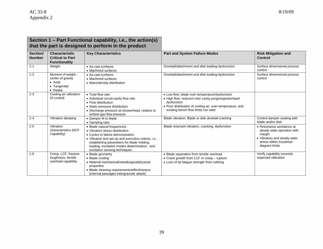
Section 1 – Part Functional capability, i.e., the action(s) that the part is designed to perform in the product Section/Number
Characteristic Critical to Part Functionality
Key Characteristics Part and System Failure Modes Risk Mitigation and Control
1-1 Weight • As-cast surfaces • Machined surfaces
Dovetail/attachment and disk loading-dysfunction
Surface dimensional process control
1-2 Moment of weight - center of gravity • Axial • Tangential • Radial
• As-cast surfaces • Machined surfaces • Mass/density distribution
Dovetail/attachment and disk loading-dysfunction Surface dimensional process control
1-3 Cooling air utilization (If cooled)
• Total flow rate • Individual circuit-cavity flow rate • Flow distribution • Static pressure distribution • Discharge pressure at showerhead, relative to
turbine gas flow pressure
• Low flow: blade over-temperature/dysfunction • High flow: reduced rotor cavity purge/ingestion/part
dysfunction • Poor distribution of cooling air: over-temperature, and
existing bench flow limits not valid
1-4 Vibration damping • Damper fit to blade • Damping ratio
Blade vibration: Blade or disk dovetail cracking Control damper seating with blade and/or disk
1-5 Vibration characteristics (HCF Capability)
• Blade natural frequencies • Vibration stress distribution • Cycles to failure demonstration • Vibration test set-up and execution criteria, i.e.,
establishing parameters for blade holding, loading, excitation modes determination, and excitation sensing techniques
Blade resonant vibration, cracking, dysfunction • Resonance avoidance at steady state operation with margin
• Vibratory and steady state stress within Goodman diagram limits
1-6 Creep, LCF, fracture toughness, tensile overload capability
• Blade geometry • Blade cooling • Material mechanical/metallurgical/physical
properties • Blade cleaning requirements/effectiveness
(internal passages-intergranular attack)
• Blade separation from tensile overload • Crack growth from LCF or creep – rupture • Loss of tip fatigue strength from rubbing
Verify capability exceeds expected utilization

AC 33-8 8/19/09 Appendix 2
40
Section 2 – Part Shape, size, dimensions and other physical measurable parameters, and interconnectivity with an engine integral part/systemSection/Number
Characteristic Critical to Part Functionality
Key Characteristics Part and System Failure Modes Risk Mitigation and Control
2-1 Dovetail or attachment
• Shape • Flatness • Tang relative location and taper • Tolerance (blade root and disk fir tree
dimensional spectrums and blade producibility limitations)
• Unbalance tang loading/blade dysfunction • Incorrect loading on disk/cracking
Dimensional process control and inspection
2-2 Platform • Width • Angel wing length
• Width: binding/damping loss, leakage/cavity ingestion • Angel wing: cavity ingestion or rotor/stator rubs
Dimensional process control
2-3 Airfoil external shape
• Aero contour/stagger angle • Thickness distribution • Twist/lean/bow
• Poor aero performance • Airfoil vibratory mode changes due to thickness distribution • Blade throat area – Bearing load, cavity purge, operability, work
split, stage loading
Surface dimensional process control
2-4 Airfoil wall thickness (if cooled)
Thickness vs. chord and span • Weight • Airfoil stress/life
Dimensional process control
2-5 Airfoil internal cavities (if cooled)
• Passage area and blockage • Turbulator height and shape • Internal wall coating
• Small area: large pressure loss, backflow, ingestion, over-temperature
• Large area: Insufficient blade cooling
Dimensional process control and inspection of passage geometry
2-6 Cross notch/cross shroud
Notch shape and thickness • Pre-twist • Seal teeth geometry
• Blade to blade tip loading o Insufficient. Excessive vibe stress, etc o Excessive. High mechanical stress, etc
• Poor tip sealing, excessive leakage, poor performance
Dimensional/coating process control
2-7 Tolerance • Variance-fluctuations in measurements • Measurement gauge repeatability and
reliability
Mechanical/Functional, failure due to vibration from nominal • Verify part is tolerant to variation
• Control of manufacturing and inspection processes

AC 33-8 8/19/09 Appendix 2
41
Section 3 – Part Materials and Processes – Properties Section/Number
Characteristic Critical to Part Functionality
Key Characteristics Part and System Failure Modes Risk Mitigation and Control
3-1 Chemistry • Major elements - % Variation • Impurities
• Poor mechanical or environmental properties • Poor coating adherence
Material selection Master heat and process control
3-2 Physical properties • Density • Thermal conductivity • Coefficient of thermal expansion • Refractive index (x-rays) • Melting point
• Excessive blade weight • Excessive thermal stresses • Interference with surrounding hardware
Verify: • Acceptable blade weight • Acceptable stresses • Blade “fit” in hot condition
3-3 Mechanical /metallurgical properties
• Modulus (vs. grain orientation) • Columnar crystal orientation angles • Bare and coated: tensile (UTS, YS,
elongation, stress rupture, creep, LCF, HCF) • Long term metallurgical stability • Thin wall effects (if cooled)
• Excessive strain-controlled stress • Undesirable natural frequency • Low material properties, blade dysfunction • Material capability consumed in operation • Low material properties, blade dysfunction
Verify: • Acceptable stresses and frequencies • Grain orientation, as required • Adequate material properties • Operational effects accounted for • Relevant properties are used
3-4 Cast structure • Grain structure (size, shape, flow, boundaries, gamma prime size and volume fraction)
• Low angle boundaries • Directional properties • Hardness • Melting point • Crack propagation rate • Refractive index
Material property reduction due to excessive grain angle or low angle boundaries, blade dysfunction
Verify that grain orientation or low angle boundaries are accounted for Process control and inspection
3-5 Environmental resistance
• Oxidation, corrosion, erosion, fretting resistance
• Elevated temperature (creep, diffusion, ageing, temp. gradients)
• Rubbing, FOD resistance
Cracking from oxidation/corrosion pitting, blade dysfunction
Verify adequate environmental properties
3-6 Environmental coating
• Coverage and thickness • Long term stability • Oxidation and corrosion resistance
• LCF property reduction due to poor coating selection/requirements, blade cracking
• Cracking from oxidation/corrosion pitting
Control of chemistry and application process Verify thermal-mechanical compatibility with base material
3-7 Notch coating • Coating material composition and density • Coverage and thickness uniformity • Coating and diffusion zone microstructure • Adhesion • Hardness • Residual stress • Stripping requirements • Bonding (interface contamination) • Compatibility with base material/other
coatings
High blade stress due to improper blade tip gapping. • Insufficient gap, high mechanical stress, etc • Excessive gap, excessive vibe stress, etc
Control of chemistry and application process
AC 33-8 8/19/09 Appendix 2
42
Section 4 – Part Materials and Processes - Processing Section/Number Characteristic
Critical to Part Functionality
Key Characteristics Part and System Failure Modes Risk Mitigation and Control
4-1 Casting cleanliness • Inclusions and porosity • Internal surface cleanliness
Crack growth from inclusion or porosity Poor coating adhesion, corrosion and oxidation
Process control (mold setup, casting process, and filtration) Process control and sequencing
4-2 Heat treatment • Time @ temperature and ramp rates • Manufacturing sequence • Atmosphere
Incorrect Gamma prime size/spacing leading to low material properties
Process control and sequencing
4-3 Welding and brazing Effect on base material properties, based on the following: • Weld or braze strength • Microstructure (grain size, shape, flow, braze
gap, defects, grain boundary precipitates, gamma prime and volume fraction
• Porosity • Diffusion zone (brazing) • Heat affected zone (welding) • Penetration (welding) • Excess braze allowance • Filler metal selection
Material property reduction
Correct sequencing of braze or weld cycles in the process Process control
4-4 Shot peen • Intensity • Coverage
Incorrect dovetail compressive stress, cracking, and blade dysfunction
Process control
4-5 Material removal – Non traditional (EDM, ECM, laser, water-jet, etc.) and conventional (machining, milling, broaching, grinding, blending, honing, lapping, stripping, etc.)
Micro cracks or recast: • Inherent to the process • Due to abusive machining Fatigue capability degradation, due to: • Surface finish • Stress risers • Chemical attack
Cracking initiation from micro-cracks or re-cast Verify part is tolerant to proposed limits Process control
4-6 Non-destructive testing (NDT)
• Acceptance limits • Sensitivity
Cracking from excessive defect size Verify part is tolerant to allowable defects
4-7 Process sequencing and Significant Process Identification and Substantiation
• Inspection • Manufacturing • Process substantiation and control (RSS, RSA,
ESA, etc)
Inadequate final part form, or defect “escape”, blade dysfunction
Verify adequate control of processes and parameters
AC 33-8 8/19/09 Appendix 2
43
Section 5 – Analysis Section/Number Characteristic
Critical to Part Functionality
Key Characteristics Part and System Failure Modes Risk Mitigation and Control
5-1 Operating conditions
• Flow path temperatures, pressures, and velocities
• Rotor speed
Inadequate part life due to analysis under-predicting part temperature, thermal or mechanical stress
Perform analysis at relevant operating conditions
5-2 Blade cooling (if cooled)
• Secondary flow circuit • Blade cooling flow • Blade cooling
Inadequate part life due to analysis over-predicting the blade cooling
5-3 LCF life analysis – airfoil and shank
• Temperature effects • Multi-axial effects • Hold time effects • Mean stress effects • Notch effects • Coating effects • Mesh size
Inadequate part life due to analysis • Using incorrect properties • Failing to address the ‘key characteristics’
Use applicable properties Select mesh size to correctly model the geometry
5-4 HCF life analysis • Temperature effects • Vibration and mean stress effects
Blade resonant vibration, cracking, dysfunction Use applicable properties and Goodman diagram
5-5 Creep and rupture life analysis
• Temperature effects • Material thickness effects
Blade rupture cracking, dysfunction Use applicable properties
5-6 Fracture mechanics • Temperature effects • Threshold stress intensity • Crack growth rate
Crack growth from defect Use applicable dA/dN curve Predict K using expected defect size
5-7 Tolerance to missing coating
• Part temperature • Thermal stress
High thermal stress or part temperature, blade dysfunction Perform analysis with predicted coating loss
5-8 Variation • Blade or engine characteristics • Degree of variation required to
assure adequate vibratory stress dampening.
Inadequate part life due to vibration Verify part is tolerant to vibration
5-9 Life calculation • Predicted stress and Temperature • Root loading profile shifts • Material Properties • Operating during part life • Life impact on disk
Inadequate part life due to analysis under-predicting Verify correct inputs to lifing process Verify correct ‘mission mixing’ used

AC 33-8 8/19/09 Appendix 2
44
Section 6 – Testing
Section/Number Characteristic Critical to Part Functionality
Key Characteristics Part and System Failure Modes Risk Mitigation and Control
6-1 Durability • Fatigue • Corrosion (hot and cold) • Erosion • Creep • Stress rupture • Tensile strength • Cooling effectiveness • Internal contamination • Cleaning requirements • Vibration
6-2 Over-temperature • Microstructure • Creep • Hot corrosion • Tensile strength
Section 7 – Potential Impact on Regulatory Requirements
Note: The regulatory requirements identified below, which are inclusive up to Amendment 20 of 14 CFR part 33, are intended as a guide to applicants when determining the applicable regulations to which they must show compliance. Those requirements listed as “Could be affected” highlight the regulations whose compliance findings are typically affected by the component or part that this template is addressing. This guide is not all-inclusive and the applicant remains responsible for identifying the certification basis of the product on which their PMA part is to be installed.
Applicable 14 CFR Part 33 Regulatory
Requirements Comments
Subpart A – General
1. 33.4 Instructions for Continued Airworthiness Could be affected ICAs including on-wing inspection requirements and on-wing limits
2. 33.5 Instruction manual for installing and operating the engine
3. 33.7 Engine ratings and operating limitations
4. 33.8 Selection of engine power and thrust ratings

AC 33-8 8/19/09 Appendix 2
45
Subpart B – Design and Construction; General
5. 33.14 Start-stop cyclic stress (low cycle fatigue) Could be affected Weight and center-of-gravity affect on rotor forces and LCF capability
6. 33.15 Materials Could be affected
7. 33.17 Fire prevention
8. 33.19 Durability Could be affected Durability; weight and failure modes relative to containment capability
9. 33.21 Engine cooling
10. 33.23 Engine mounting attachments and structure
11. 33.25 Accessory attachments
12. 33.27 Turbine, compressor, fan, and turbo-supercharger rotors
Could be affected Weight affect on rotor forces during over-speed
13. 33.28 Electrical and electronic control systems
14. 33.29 Instrumentation connection
Subpart E – Design and Construction:
Turbine Aircraft Engines
15. 33.62 Stress analysis Could be affected
16. 33.63 Vibration Could be affected Blade vibration-Design
17. 33.65 Surge and stall characteristics Could be affected Turbine effective area-Operating line migration, Blade-Rub strip interaction
18. 33.66 Bleed air systems
19. 33.67 Fuel system
20. 33.68 Induction system icing (Operability aspects)
21. 33.69 Ignition system
22. 33.71 Lubrication system
23. 33.72 Hydraulic actuating system
24. 33.73 Power or thrust response Could be affected Turbine efficiency/performance
25. 33.74 Continued rotation
26. 33.75 Safety analysis Could be affected Turbine blade release-Case containment

AC 33-8 8/19/09 Appendix 2
46
Subpart E – Design and Construction: Turbine Aircraft Engines
27. 33.76 Bird ingestion (Operability aspects of ingestion)
28. 33.77 Foreign object ingestion (Operability aspects of ingestion)
29. 33.78 Rain and hail ingestion
30. 33.79 Fuel burning thrust augmenter
Subpart F – Block Tests; Turbine Aircraft Engines
31. 33.83 Vibration test Could be affected Blade vibration
32. 33.85 Calibration tests
33. 33.87 Endurance test Could be affected Blade durability
34. 33.88 Engine over temperature test Could be affected Blade over temperature capability
35. 33.89 Operation test
36. 33.90 Initial maintenance inspection Could be affected Blade in-service inspection limits
37. 33.91 Engine component tests
38. 33.92 Rotor locking tests
39. 33.93 Teardown inspection
40. 33.94 Blade containment and rotor unbalance tests (Weight changes)
Could be affected Failure of the most critical turbine blade while operating at maximum permissible r.p.m.
41. 33.95 Engine-propeller system tests
42. 33.96 Engine tests in auxiliary power unit (APU) mode
43. 33.97 Thrust reversers
44. 33.99 General conduct of block tests
45. Part 33 - Appendix A – Instructions for Continued Airworthiness
Could be affected
46. Part 33 - Appendix B - Certification Standard Atmospheric Concentrations of Rain and Hail

AC 33-8 8/19/09 Appendix 2
47
Template #5: Turbine Vane Cooled
Nomenclature for Generic Component Features
(all features may not be applicable)

AC 33-8 8/19/09 Appendix 2
48
Section 1 – Part Functional capability, i.e., the action(s) that the part is designed to perform in the product Section/Number
Characteristic Critical to Part Functionality
Key Characteristics Part and System Failure Modes Risk Mitigation and Control
1-1 Weight • As-cast surfaces • Machined surfaces
Engine mass and CG
Surface dimensional process control
1-2 Cooling air utilization • Total flow rate • Individual circuit-cavity flow rate • Flow distribution • Static pressure distribution • Discharge pressure at showerhead, relative to
turbine gas flow pressure • Distribution of post and pre impingement air to
the rotor cavities
• Low vane cooling flow: vane over-temperature/dysfunction • High vane cooling flow, and/or low purge cavity delivery
flow; reduced rotor cavity purge/ingestion/part dysfunction • Poor distribution of cooling air: over-temperature, and
existing bench flow limits not valid
1-3 Structural strength and vibration characteristics
• Vane natural frequencies • Major load path
• Vane resonant vibration, cracking, dysfunction • Static structure malfunction
• Resonance avoidance at steady state operation with margin
• Vibratory and steady state stress within Goodman diagram limits
1-4 Creep, LCF, fracture toughness, tensile overload capability
• Vane geometry • Vane cooling • Material mechanical/metallurgical/physical
properties • Vane cleaning requirements/effectiveness
(internal passages-intergranular attack)
• Crack growth from LCF or creep – rupture
Verify capability exceeds expected utilization

AC 33-8 8/19/09 Appendix 2
49
Section 2 – Part Shape, size, dimensions and other physical measurable parameters, and interconnectivity with an engine integral part/systemSection/Number
Characteristic Critical to Part Functionality
Key Characteristics Part and System Failure Modes Risk Mitigation and Control
2-1 Inner and outer platforms
• Arc length • Axial location of forward and aft face • Functional fits at interfaces • Part/assembly locating features (axial, radial
and tangential) • Inner and outer gas path contours • Air sealing surfaces (axial, radial and
tangential) • Surface finish
• Unbalance: tang loading/dysfunction • Width: binding, leakage/cavity ingestion
Dimensional process control and inspection
2-2 Airfoil external shape
• Aero contour/stagger angle • Thickness distribution • Effects on down stream turbine blades
• Poor aero performance • Airfoil vibratory mode changes due to thickness distribution • Vane throat area – bearing load, cavity purge, operability, work
split, stage loading
Surface dimensional process control Assessment of exit flow characteristics
2-3 Airfoil wall thickness
Thickness vs. chord and span • Weight • Airfoil stress/life
Dimensional process control
2-4 Airfoil internal cavities
• Passage area and blockage • Turbulator height and shape • Internal wall coating
• Small area: large pressure loss, backflow, ingestion, over-temperature
• Large area: insufficient vane cooling
Dimensional process control and inspection of passage geometry
2-5 Tolerance • Variance-fluctuations in measurements • Measurement gauge repeatability and
reliability
Mechanical/Functional, failure due to vibration from nominal • Verify part is tolerant to variation
• Control of manufacturing and inspection processes
2-6
Cooling baffle • Mass flow • Standoff
• Low flow: excessive pressure loss, back flow, etc • High flow: low impingement cooling, excessive part temp, etc • Low standoff: low impingement cooling, excessive part temp, etc
• Verify part is tolerant to variation
• Control of manufacturing and inspection processes
2-7
Interstage seal • Dimension • Honeycomb dimensions
• Insufficient interstage sealing: Insufficient upstream cavity purge, etc
• Excessive interstage sealing: Insufficient downstream cavity purge, etc
• Poor cutting characteristics, rubbing, thermal instability, etc
• Verify part is tolerant to variation
• Control of manufacturing and inspection processes
2-8 Airfoil to platform filets
• Filet profile • Failure due to stress concentration. • Dimensional process control.

AC 33-8 8/19/09 Appendix 2
50
Section 3 – Part Materials and Processes – Properties Section/Number
Characteristic Critical to Part Functionality
Key Characteristics Part and System Failure Modes Risk Mitigation and Control
3-1 Chemistry • Major elements - % variation • Impurities
• Poor mechanical or environmental properties • Poor TBC adherence
Material selection Master heat and Process control
3-2 Physical properties • Density • Coefficient of thermal expansion • Refractive index (x-rays)
• Excessive vane weight • Excessive thermal stresses • Interference with surrounding hardware
Verify: • Acceptable vane weight • Acceptable stresses • Vane “fit” in hot condition
3-3 Mechanical /metallurgical properties
• Modulus (vs. grain orientation) • Columnar crystal orientation angles • Bare and coated: tensile (UTS, YS, elongation,
stress rupture, creep, LCF, HCF) • Long term metallurgical stability • Thin wall effects
• Excessive strain-controlled stress • Undesirable natural frequency • Low material properties, vane dysfunction • Material capability consumed in operation
Verify: • Acceptable stresses and frequencies • Grain orientation, as required • Adequate material properties • Operational effects accounted for • Relevant properties are used
3-4 Cast structure • Grain structure (size, shape, flow, boundaries, gamma prime size and volume fraction, recrystallization)
• Inclusions • Freckling • Porosity • High angle boundaries - directional properties • Hardness • Melting point • Crack propagation rate • Refractive index
Material property reduction due to excessive grain angle or high angle boundaries (HAB),
Verify that grain orientation or high angle boundaries are accounted for Process control and inspection
3-5 Environmental resistance
• Oxidation, corrosion, erosion, fretting resistance • Elevated temperature (creep, diffusion, ageing,
temp. gradients) • FOD resistance
Cracking from oxidation/corrosion pitting, vane dysfunction
Verify adequate environmental properties
3-6 Environmental coating
• Coverage and thickness • Long term stability • Oxidation and corrosion resistance
• LCF property reduction due to poor coating selection/requirements, vane cracking
• Cracking from oxidation/corrosion pitting
• Control of chemistry and application process
• Verify thermal-mechanical compatibility with base material

AC 33-8 8/19/09 Appendix 2
51
Section 3 – Part Materials and Processes – Properties Section/Number
Characteristic Critical to Part Functionality
Key Characteristics Part and System Failure Modes Risk Mitigation and Control
3-7 Thermal barrier coating
• Coating material composition and density • Thermal conductivity (coefficient of thermal
expansion) • Coverage and thickness uniformity • Coating and diffusion zone microstructure • Adhesion • Oxidation • Resistance to spalling, sintering and erosion • Hardness • Residual Stress • Stripping requirements • Bonding (interface contamination) • Compatibility with base material/other coatings
High thermal stresses or part temperature, vane dysfunction
• Control of chemistry and application process
• Verify part is tolerant to missing TBC • No high TBC temperatures that
accelerate spalling, or molten dirt infiltration
Section 4 – Part Materials and Processes - Processing Section/Number Characteristic
Critical to Part Functionality
Key Characteristics Part and System Failure Modes Risk Mitigation and Control
4-1 Casting cleanliness • Inclusions and porosity • Internal surface cleanliness
Crack growth from inclusion or porosity Poor coating adhesion, corrosion and oxidation
• Process control (mold setup, casting process, and filtration)
• Process control and sequencing
4-2 Heat treatment • Time @ temperature and ramp rates • Manufacturing sequence • Atmosphere
Incorrect Gamma prime size/spacing leading to low material properties
Process control and sequencing
4-3 Welding and brazing Effect on base material properties, based on the following: • Weld or braze strength • Microstructure (grain size, shape, flow, braze
gap, defects, grain boundary precipitates, gamma prime and volume fraction
• Porosity • Diffusion zone (brazing) • Heat affected zone (welding) • Penetration (welding) • Excess braze allowance • Filler metal selection
Material property reduction
• Correct sequencing of braze or weld cycles in the process
• Process control
4-4 Shot peen • Intensity • Coverage
Incorrect compressive stress, cracking, and vane dysfunction
Process control

AC 33-8 8/19/09 Appendix 2
52
Section 4 – Part Materials and Processes - Processing Section/Number Characteristic
Critical to Part Functionality
Key Characteristics Part and System Failure Modes Risk Mitigation and Control
4-5 Material removal – Non traditional (EDM, ECM, laser, water-jet, etc.) and conventional (machining, milling, broaching, grinding, blending, honing, lapping, stripping, etc.)
Micro cracks or recast: • Inherent to the process • Due to abusive machining Fatigue capability degradation, due to: • Surface finish • Stress risers • Chemical attack
Cracking initiation from micro-cracks or re-cast • Verify part is tolerant to proposed limits
• Process control
4-6 Non-destructive testing (NDT)
• Acceptance limits • Sensitivity
Cracking from excessive defect size Verify part is tolerant to allowable defects
4-7 Process sequencing and significant process identification and substantiation
• Inspection • Manufacturing • Process substantiation and control (RSS, RSA,
ESA, etc)
Inadequate final part form, or defect “escape”, vane dysfunction
Verify adequate control of processes and parameters
Section 5 – Analysis Section/Number Characteristic
Critical to Part Functionality
Key Characteristics Part and System Failure Modes Risk Mitigation and Control
5-1 Operating conditions
• Flow path temperatures, pressures, and velocities • Nozzle Area
Compressor operability Perform analysis at relevant operating conditions
5-2 Vane cooling • Secondary flow circuit • Vane cooling flow • Vane cooling
Inadequate part life due to analysis over-predicting the vane cooling
5-3 LCF/TMF life analysis – airfoil and shrouds
• Temperature effects • Multi-axial effects • Hold time effects • Mean stress effects • Notch effects • Coating effects • Mesh size
Inadequate part life due to analysis • Using incorrect properties • Failing to address the ‘key characteristics’
Use applicable properties Select mesh size to correctly model the geometry
5-4 HCF life analysis • Temperature effects • Vibration and mean stress effects
Vane resonant vibration, cracking, dysfunction Use applicable properties and Goodman Diagram
5-5 Creep and rupture life analysis
• Temperature effects • Material thickness effects
Vane rupture cracking, dysfunction Use applicable properties
5-6 Fracture mechanics • Temperature effects • Threshold stress intensity • Crack growth rate
Crack growth from defect • Use applicable dA/dN curve • Predict K using expected defect
size 5-7 Tolerance to
missing TBC • Part temperature • Thermal stress
High thermal stress or part temperature, vane dysfunction
Perform analysis with predicted TBC loss

AC 33-8 8/19/09 Appendix 2
53
Section 5 – Analysis Section/Number Characteristic
Critical to Part Functionality
Key Characteristics Part and System Failure Modes Risk Mitigation and Control
5-8 Variation • Nozzle or engine characteristics Inadequate part life due to vibration Verify part is tolerant to vibration 5-9 Life calculation • Predicted stress and temperature
• Material properties • Operating during part life
Inadequate part life due to analysis under-predicting
Verify correct inputs to lifing process Verify correct ‘mission mixing’ used
Section 6 – Testing
Section/Number Characteristic Critical to Part Functionality
Key Characteristics Part and System Failure Modes Risk Mitigation and Control
6-1 Durability • Fatigue • Corrosion (hot and cold) • Erosion • Creep • Stress rupture • Tensile strength • Cooling effectiveness • Internal contamination • Cleaning requirements
6-2 Over-temperature • Microstructure • Creep • Hot corrosion • Tensile strength

AC 33-8 8/19/09 Appendix 2
54
Section 7 – Potential Impact on Regulatory Requirements
Note: The regulatory requirements identified below, which are inclusive up to Amendment 20 of 14 CFR part 33, are intended as a guide to applicants when determining the applicable regulations to which they must show compliance. Those requirements listed as “Could be affected” highlight the regulations whose compliance findings are typically affected by the component or part that this template is addressing. This guide is not all-inclusive and the applicant remains responsible for identifying the certification basis of the product on which their PMA part is to be installed.
Applicable 14 CFR Part 33 Regulatory Requirements
Comments
Subpart A – General
1. 33.4 Instructions for Continued Airworthiness Could be affected ICAs including on-wing inspection requirements and on-wing limits
2. 33.5 Instruction manual for installing and operating the engine
3. 33.7 Engine ratings and operating limitations
4. 33.8 Selection of engine power and thrust ratings
Subpart B – Design and Construction;
General
5. 33.14 Start-stop cyclic stress (low cycle fatigue) Could be affected Turbine cooling
6. 33.15 Materials Could be affected
7. 33.17 Fire prevention
8. 33.19 Durability Could be affected
9. 33.21 Engine cooling Could be affected
10. 33.23 Engine mounting attachments and structure
11. 33.25 Accessory attachments
12. 33.27 Turbine, compressor, fan, and turbo-supercharger rotors
13. 33.28 Electrical and electronic control systems
14. 33.29 Instrumentation connection

AC 33-8 8/19/09 Appendix 2
55
Subpart E – Design and Construction; Turbine Aircraft Engines
15. 33.62 Stress analysis Could be affected Turbine cooling
16. 33.63 Vibration Could be affected Vane vibration
17. 33.65 Surge and stall characteristics Could be affected Turbine effective area-Operating line migration
18. 33.66 Bleed air systems
19. 33.67 Fuel system
20. 33.68 Induction system icing (Operability aspects)
21. 33.69 Ignition system
22. 33.71 Lubrication system
23. 33.72 Hydraulic actuating system
24. 33.73 Power or thrust response Could be affected Turbine efficiency/performance
25. 33.74 Continued rotation
26. 33.75 Safety analysis Could be affected Turbine vane release – downstream effects
27. 33.76 Bird ingestion (Operability aspects of ingestion)
28. 33.77 Foreign object ingestion (Operability aspects of ingestion)
29. 33.78 Rain and hail ingestion
30. 33.79 Fuel burning thrust augmenter
Subpart F – Block Tests; Turbine Aircraft Engines
31. 33.83 Vibration test Could be affected Vibration
32. 33.85 Calibration tests
33. 33.87 Endurance test Could be affected Vane durability
34. 33.88 Engine over temperature test Could be affected Vane over temperature capability
35. 33.89 Operation test
36. 33.90 Initial maintenance inspection Could be affected Blade in-service inspection limits

AC 33-8 8/19/09 Appendix 2
56
Subpart F – Block Tests; Turbine Aircraft Engines
37. 33.91 Engine component tests
38. 33.92 Rotor locking tests
39. 33.93 Teardown inspection
40. 33.94 Blade containment and rotor unbalance tests (Weight changes)
41. 33.95 Engine-propeller system tests
42. 33.96 Engine tests in auxiliary power unit (APU) mode
43. 33.97 Thrust reversers
44. 33.99 General conduct of block tests
45. Part 33 - Appendix A – Instructions for Continued
Airworthiness Could be affected
46. Part 33 - Appendix B - Certification Standard Atmospheric Concentrations of Rain and Hail

AC 33-8 8/19/09 Appendix 2
57
Template #6: Turbine Vane Uncooled
Nomenclature for Generic Component Features (all features may not be applicable)
Outer Shroud or Ring Inner Shroud, Ring or Platform
Vane Airfoil
Vane Packets (may be segmented or continuous)

AC 33-8 8/19/09 Appendix 2
58
Section 1 – Part Functional capability, i.e., the action(s) that the part is designed to perform in the product Section/Number
Characteristic Critical to Part Functionality
Key Characteristics Part and System Failure Modes Risk Mitigation and Control
1-1 Weight • As-cast surfaces • Machined surfaces
Engine mass and CG
Surface dimensional process control
1-2 Structural strength and vibration characteristics
• Vane natural frequencies • Major load path
• Vane resonant vibration, cracking, dysfunction • Static structure malfunction
• Resonance avoidance at steady state operation with margin
• Vibratory and steady state stress within Goodman diagram limits
1-3 Creep, LCF, fracture toughness, tensile overload capability
• Vane geometry • Vane cooling • Material mechanical/metallurgical/physical
properties • Vane cleaning requirements/effectiveness
(internal passages-intergranular attack)
Crack growth from LCF or creep – rupture
Verify capability exceeds expected utilization
Section 2 – Part Shape, size, dimensions and other physical measurable parameters, and interconnectivity with an engine integral part/system Section/Number
Characteristic Critical to Part Functionality
Key Characteristics Part and System Failure Modes Risk Mitigation and Control
2-1 Inner and outer shroud or platform
• Arc length • Axial location of forward and aft face • Functional fits at interfaces • Part/assembly locating features (axial, radial and
tangential) • Inner and outer airsealing surfaces (axial, radial
and tangential) • Inner and outer gas path contours • Sealing surfaces, surface finish
Unbalance tang loading/blade dysfunction Dimensional process control and inspection
2-2 Platform • Width Width: binding, leakage/cavity ingestion
Dimensional process control
2-3 Airfoil external shape
• Aero contour/stagger angle • Thickness distribution
• Poor aero performance • Airfoil vibratory mode changes due to thickness distribution • Effect on downstream turbine blade vibratory response • Vane throat area – bearing load, cavity purge, operability,
work split, stage loading • Weight
Surface dimensional process control

AC 33-8 8/19/09 Appendix 2
59
Section 2 – Part Shape, size, dimensions and other physical measurable parameters, and interconnectivity with an engine integral part/system 2-4 Tolerance • Variance-fluctuations in measurements
• Measurement gauge repeatability and reliability Mechanical/functional, failure due to vibration from nominal • Verify part is tolerant to
variation • Control of manufacturing and
inspection processes 2-5
Interstage seal • Dimension • Honeycomb dimensions
• Insufficient interstage sealing: Insufficient upstream cavity purge, etc.
• Excessive interstage sealing: Insufficient downstream cavity purge, etc.
• Poor cutting characteristics, rubbing, thermal instability, etc
• Verify part is tolerant to variation
• Control of manufacturing and inspection processes
2-6 Airfoil to platform filets
• Filet profile Failure due to stress concentration • Dimensional process control
Section 3 – Part Materials and Processes – Properties Section/Number
Characteristic Critical to Part Functionality
Key Characteristics Part and System Failure Modes Risk Mitigation and Control
3-1 Chemistry • Major elements - % variation • Impurities
• Poor mechanical or environmental properties • Poor TBC adherence
Material selection Master heat and process control
3-2 Physical properties • Density • Coefficient of thermal expansion • Refractive Index (x-rays)
• Excessive Vane Weight • Excessive thermal stresses • Interference with surrounding hardware
Verify: • Acceptable vane weight • Acceptable stresses • Vane “fit” in hot condition
3-3 Mechanical /metallurgical properties
• Modulus (vs. grain orientation) • Columnar crystal orientation angles • Bare and coated: tensile (UTS, YS,
elongation, stress rupture, creep, LCF, HCF)
• Long term metallurgical stability
• Excessive strain-controlled stress • Undesirable natural frequency • Low material properties, vane dysfunction • Material capability consumed in operation
Verify: • Acceptable stresses and frequencies • Grain orientation, as required • Adequate material properties • Operational effects accounted for • Relevant properties are used
3-4 Cast structure • Grain structure (size, shape, flow, boundaries, gamma prime size and volume fraction, recrystallization)
• Inclusions • Freckling • Porosity • High angle boundaries directional
properties • Hardness • Melting point • Crack propagation rate • Refractive index
Material property reduction due to excessive grain angle or high angle boundaries (HAB),
• Verify that grain orientation or high angle boundaries are accounted for
• Process control and inspection

AC 33-8 8/19/09 Appendix 2
60
Section 3 – Part Materials and Processes – Properties Section/Number
Characteristic Critical to Part Functionality
Key Characteristics Part and System Failure Modes Risk Mitigation and Control
3-5 Environmental resistance
• Oxidation, corrosion, erosion, fretting resistance
• Elevated temperature (creep, diffusion, ageing, temp. gradients)
• FOD resistance
Cracking from oxidation/corrosion pitting, vane dysfunction • Verify adequate environmental properties
3-6 Environmental coating
• Coverage and thickness • Long term stability • Oxidation and corrosion resistance
• LCF property reduction due to poor coating selection/requirements, vane cracking
• Cracking from oxidation/corrosion pitting
• Control of chemistry and application process
• Verify thermal-mechanical compatibility with base material
3-7 Thermal barrier coating (if used)
• Coating material composition and density • Thermal conductivity (coefficient of thermal
expansion) • Coverage and thickness uniformity • Coating and diffusion zone microstructure • Adhesion • Oxidation • Resistance to spalling, sintering and
erosion • Hardness • Residual stress • Stripping requirements • Bonding (interface contamination) • Compatibility with base material/other
coatings
High thermal stresses or part temperature, vane dysfunction • Control of chemistry and application process
• Verify part is tolerant to missing TBC • No high TBC temperatures that
accelerate spalling, or molten dirt infiltration
Section 4 – Part Materials and Processes - Processing Section/Number Characteristic
Critical to Part Functionality
Key Characteristics Part and System Failure Modes Risk Mitigation and Control
4-1 Casting cleanliness • Inclusions and porosity • Internal surface cleanliness
Crack growth from inclusion or porosity Poor coating adhesion, corrosion and oxidation
• Process control (mold setup, casting process, and filtration)
• Process control and sequencing
4-2 Heat treatment • Time @ temperature and ramp rates • Manufacturing sequence • Atmosphere
Incorrect Gamma prime size/spacing leading to low material properties
Process control and sequencing

AC 33-8 8/19/09 Appendix 2
61
Section 4 – Part Materials and Processes - Processing Section/Number Characteristic
Critical to Part Functionality
Key Characteristics Part and System Failure Modes Risk Mitigation and Control
4-3 Welding and brazing Effect on base material properties, based on the following: • Weld or braze strength • Microstructure (grain size, shape, flow, braze
gap, defects, grain boundary precipitates, gamma prime and volume fraction
• Porosity • Diffusion zone (brazing) • Heat affected zone (welding) • Penetration (welding) • Excess braze allowance • Filler metal selection
Material property reduction
Correct sequencing of braze or weld cycles in the process Process control
4-4 Shot peen • Intensity • Coverage
Incorrect compressive stress, cracking, and vane dysfunction
Process control
4-5 Material removal – Non traditional (EDM, ECM, laser, water-jet, etc.) and conventional (machining, milling, broaching, grinding, blending, honing, lapping, stripping, etc.)
Micro cracks or recast: • Inherent to the process • Due to abusive machining Fatigue capability degradation, due to: • Surface finish • Stress risers • Chemical attack
Cracking initiation from micro-cracks or re-cast Verify part is tolerant to proposed limits Process control
4-6 Non-destructive testing (NDT)
• Acceptance limits • Sensitivity
Cracking from excessive defect size Verify part is tolerant to allowable defects
4-7 Process sequencing and significant process identification and substantiation
• Inspection • Manufacturing • Process substantiation and control (RSS, RSA,
ESA, etc)
Inadequate final part form, or defect “escape”, vane dysfunction
Verify adequate control of processes and parameters
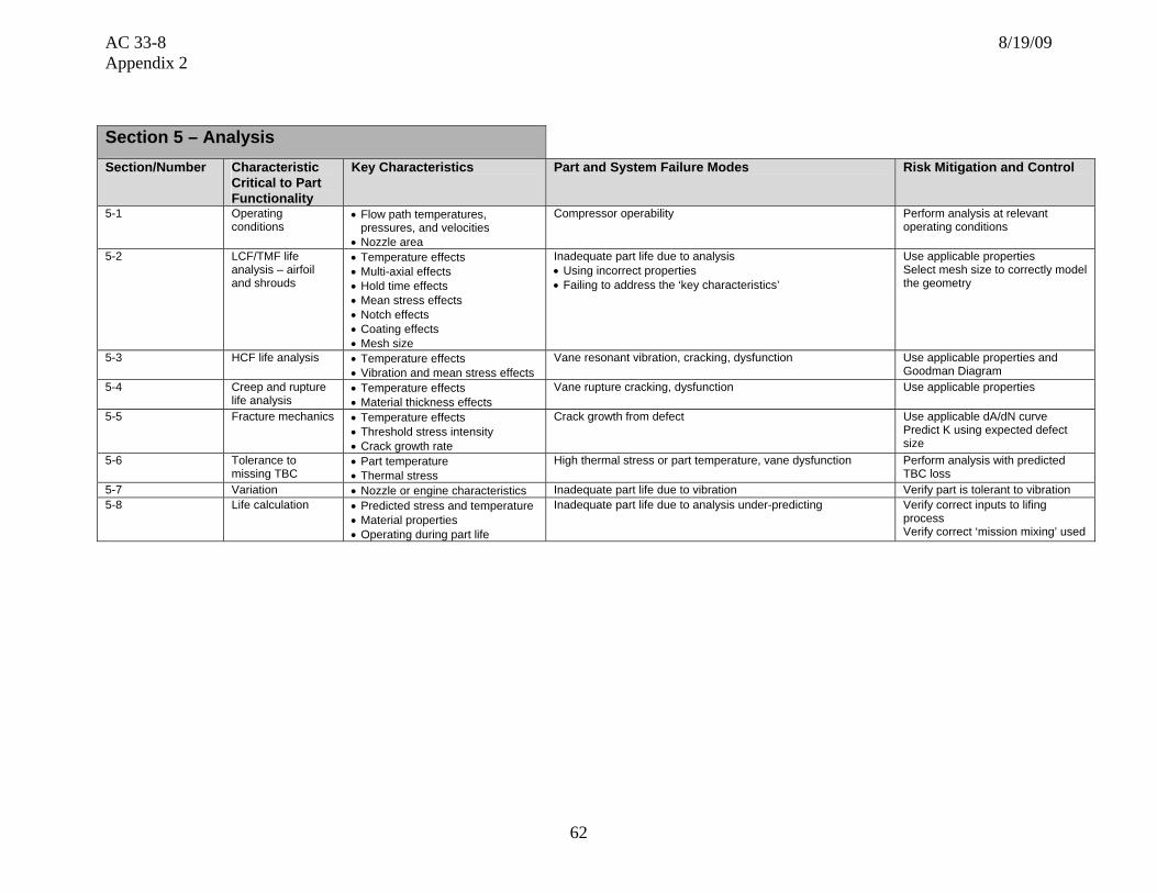
AC 33-8 8/19/09 Appendix 2
62
Section 5 – Analysis Section/Number Characteristic
Critical to Part Functionality
Key Characteristics Part and System Failure Modes Risk Mitigation and Control
5-1 Operating conditions
• Flow path temperatures, pressures, and velocities
• Nozzle area
Compressor operability Perform analysis at relevant operating conditions
5-2 LCF/TMF life analysis – airfoil and shrouds
• Temperature effects • Multi-axial effects • Hold time effects • Mean stress effects • Notch effects • Coating effects • Mesh size
Inadequate part life due to analysis • Using incorrect properties • Failing to address the ‘key characteristics’
Use applicable properties Select mesh size to correctly model the geometry
5-3 HCF life analysis • Temperature effects • Vibration and mean stress effects
Vane resonant vibration, cracking, dysfunction Use applicable properties and Goodman Diagram
5-4 Creep and rupture life analysis
• Temperature effects • Material thickness effects
Vane rupture cracking, dysfunction Use applicable properties
5-5 Fracture mechanics • Temperature effects • Threshold stress intensity • Crack growth rate
Crack growth from defect Use applicable dA/dN curve Predict K using expected defect size
5-6 Tolerance to missing TBC
• Part temperature • Thermal stress
High thermal stress or part temperature, vane dysfunction Perform analysis with predicted TBC loss
5-7 Variation • Nozzle or engine characteristics Inadequate part life due to vibration Verify part is tolerant to vibration 5-8 Life calculation • Predicted stress and temperature
• Material properties • Operating during part life
Inadequate part life due to analysis under-predicting Verify correct inputs to lifing process Verify correct ‘mission mixing’ used

AC 33-8 8/19/09 Appendix 2
63
Section 6 – Testing
Section/ Number
Characteristic Critical to Part Functionality
Key Characteristics Part and System Failure Modes Risk Mitigation and Control
6-1 Durability • Fatigue • Corrosion (hot and cold) • Erosion • Creep • Stress rupture • Tensile strength • Internal contamination • Cleaning requirements
6-2 Over-temperature • Microstructure • Creep • Hot corrosion • Tensile strength
Section 7 – Potential Impact on Regulatory Requirements
Note: The regulatory requirements identified below, which are inclusive up to Amendment 20 of 14 CFR part 33, are intended as a guide to applicants when determining the applicable regulations to which they must show compliance. Those requirements listed as “Could be affected” highlight the regulations whose compliance findings are typically affected by the component or part that this template is addressing. This guide is not all-inclusive and the applicant remains responsible for identifying the certification basis of the product on which their PMA part is to be installed.
Applicable 14 CFR Part 33 Regulatory
Requirements Comments
Subpart A – General
1. 33.4 Instructions for Continued Airworthiness Could be affected ICAs including on-wing inspection requirements and on-wing limits
2. 33.5 Instruction manual for installing and operating the engine
3. 33.7 Engine ratings and operating limitations
4. 33.8 Selection of engine power and thrust ratings

AC 33-8 8/19/09 Appendix 2
64
Subpart B – Design and Construction; General
5. 33.14 Start-stop cyclic stress (low cycle fatigue)
6. 33.15 Materials Could be affected
7. 33.17 Fire prevention
8. 33.19 Durability Could be affected
9. 33.21 Engine cooling
10. 33.23 Engine mounting attachments and structure
11. 33.25 Accessory attachments
12. 33.27 Turbine, compressor, fan, and turbo-supercharger rotors
13. 33.28 Electrical and electronic control systems
14. 33.29 Instrumentation connection
Subpart E – Design and Construction: Turbine Aircraft Engines
15. 33.62 Stress Analysis
16. 33.63 Vibration Could be affected Vane vibration
17. 33.65 Surge and stall characteristics Could be affected Turbine effective area-Operating line migration
18. 33.66 Bleed air systems
19. 33.67 Fuel system
20. 33.68 Induction system icing (Operability aspects)
21. 33.69 Ignition system
22. 33.71 Lubrication system
23. 33.72 Hydraulic actuating system
24. 33.73 Power or thrust response Could be affected Turbine efficiency/performance
25. 33.74 Continued rotation
26. 33.75 Safety analysis Could be affected Turbine vane release

AC 33-8 8/19/09 Appendix 2
65
Subpart E – Design and Construction: Turbine Aircraft Engines
27. 33.76 Bird ingestion (Operability aspects of ingestion)
28. 33.77 Foreign object ingestion (Operability aspects of ingestion)
29. 33.78 Rain and hail ingestion
30. 33.79 Fuel burning thrust augmenter
Subpart F – Block Tests; Turbine Aircraft Engines
31. 33.83 Vibration test Could be affected Vibration
32. 33.85 Calibration tests
33. 33.87 Endurance test Could be affected Vane durability
34. 33.88 Engine over temperature test Could be affected Vane over temperature capability
35. 33.89 Operation test
36. 33.90 Initial maintenance inspection Could be affected Blade in-service inspection limits
37. 33.91 Engine component tests
38. 33.92 Rotor locking tests
39. 33.93 Teardown inspection
40. 33.94 Blade containment and rotor unbalance tests (Weight changes)
41. 33.95 Engine-propeller system tests
42. 33.96 Engine tests in auxiliary power unit (APU) mode
43. 33.97 Thrust reversers
44. 33.99 General conduct of block tests
45. Part 33 - Appendix A – Instructions for Continued Airworthiness
Could be affected
46. Part 33 - Appendix B- Certification Standard Atmospheric Concentrations of Rain and Hail
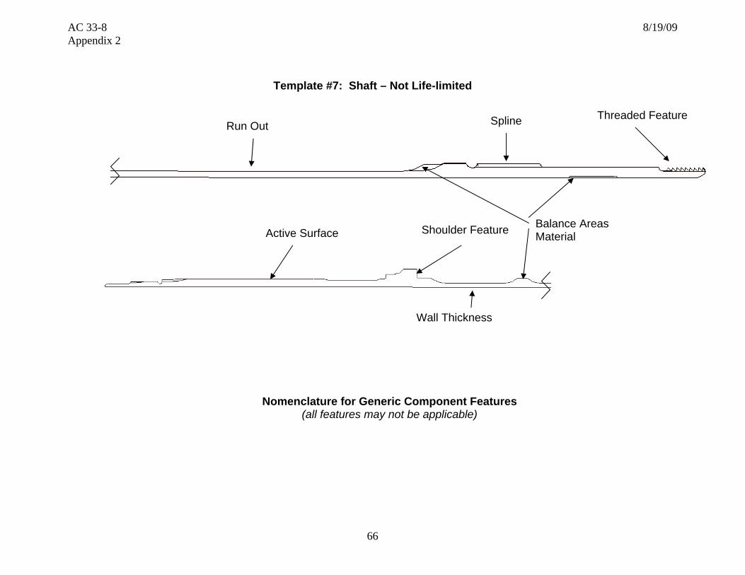
AC 33-8 8/19/09 Appendix 2
66
Template #7: Shaft – Not Life-limited
Nomenclature for Generic Component Features (all features may not be applicable)
Active Surface
Spline Threaded Feature
Balance Areas Material
Wall Thickness
Run Out
Shoulder Feature

AC 33-8 8/19/09 Appendix 2
67
Section 1 – Part Functional capability, i.e., the action(s) that the part is designed to perform in the product Section/Number
Characteristic Critical to Part Functionality
Key Characteristics Part and System Failure Modes Risk Mitigation and Control
1-1 Weight • As-forged surfaces • Machined surfaces
• Inertia • Surface dimensional process control
1-2 Shaft geometry • Diameters • Attachment point form • Surface finish • Surface hardness
• Correct length • Heat dissipation • Vibration response
• Dimensional control • Machining process control
1-3 Vibration characteristics (HCF capability)
• Shaft natural frequencies • Vibration stress distribution • Cycles to failure demonstration
• Shaft resonant vibration, cracking • Resonance avoidance at steady state operation with margin
• Vibratory and steady state stress within Goodman diagram limits
1-4 LCF, fracture toughness, tensile overload capability
• Shaft geometry • Material mechanical/metallurgical/physical
properties
• Shaft separation from overload • Crack growth from LCF, HCF, or HCF/LCF interaction
• Verify capability exceeds expected duty cycle
1-5 Attachment features • Surface finish • Press fit • Retaining thread • Wear resistance on mating component • Splines
• Surface fret • Bearing spinning • Dimensional checks
• Surface dimensional process control
• Verify acceptable wear couple
Section 2 – Part Shape, size, dimensions and other physical measurable parameters, and interconnectivity with an engine integral part/systemSection/Number
Characteristic Critical to Part Functionality
Key Characteristics Part and System Failure Modes Risk Mitigation and Control
2-1 Shaft features • Shape • Surface finish • Internal/external diameter • Edge break, relief cuts • Splines • Threads • Integral raceways • Oil holes
• Vibration • Resonant frequencies • Scuffing
• Dimensional process control and inspection
2-2 Feature locations • Distance to features from datum • Parts mislocated with in engine • Dimensional process control

AC 33-8 8/19/09 Appendix 2
68
Section 2 – Part Shape, size, dimensions and other physical measurable parameters, and interconnectivity with an engine integral part/systemSection/Number
Characteristic Critical to Part Functionality
Key Characteristics Part and System Failure Modes Risk Mitigation and Control
2-3 Wall thickness • Transition areas • Thickness distribution • Attaching features • Dampening features • Balancing features
• Gear vibratory mode changes due to thickness distribution • Weight – excessive inertia load • Stress/life
• Surface dimensional process control
2-4 Tolerance • Variance-fluctuations in measurements • Measurement gauge repeatability and
reliability
• Mechanical/functional, failure due to variation from nominal • Verify part is tolerant to variation
• Control of manufacturing and inspection processes
Section 3 – Part Materials and Processes – Properties Section/Number
Characteristic Critical to Part Functionality
Key Characteristics Part and System Failure Modes Risk Mitigation and Control
3-1 Chemistry • Major elements - % variation • Impurities
Poor mechanical or environmental properties Material selection Process control
3-2 Physical properties • Density • Coefficient of thermal expansion • Melting point
• Excessive weight • Excessive loading on retaining features
Verify: • Acceptable stresses • Operating conditions
3-3 Mechanical /metallurgical properties
• Modulus • Forging grain flow angles • Tensile, UTS, YS, elongation, stress rupture,
creep, LCF, HCF • Endurance limit • Fracture mechanics • Plasticity model • Sudden overload properties • Surface hardness
• Undesirable natural frequencies • Low material properties: shaft yield or break • Spalling during operation
Verify: • Acceptable stresses and frequencies • Forging grain flow as required • Adequate material properties • Operational effects accounted for • Impact testing
3-4 Forged structure • Grain structure (size, shape, flow, boundaries)
• Directional properties • Hardness • Forging laps • Homogeneity of forging work throughout part
Material property reduction due to abnormal grain structure, vibration,
Verify that variations in grain structure are accounted for Process control & inspection
3-5 Environmental resistance
• Oxidation, corrosion, fretting resistance • Elevated temperature stress relaxation • Surface coating
• Spalling from oxidation/corrosion pitting • Property reduction due to extreme oil overtemperature
or lack of cooling oil
Verify adequate environmental properties
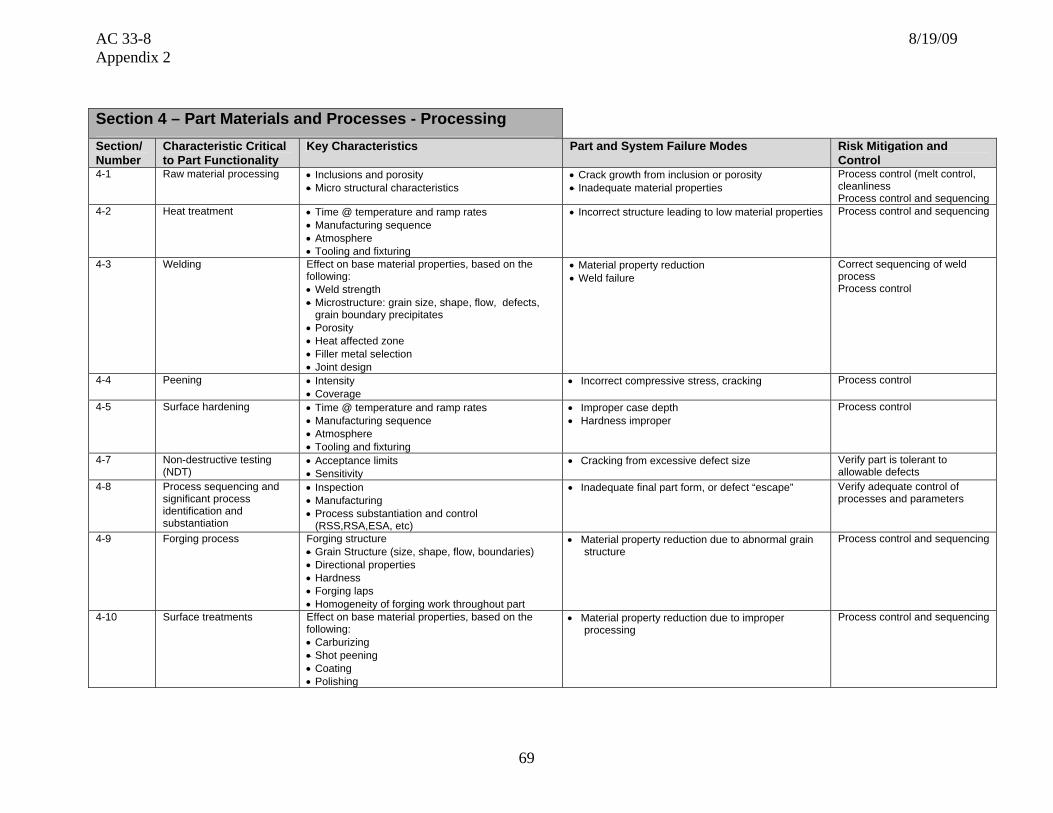
AC 33-8 8/19/09 Appendix 2
69
Section 4 – Part Materials and Processes - Processing Section/ Number
Characteristic Critical to Part Functionality
Key Characteristics Part and System Failure Modes Risk Mitigation and Control
4-1 Raw material processing • Inclusions and porosity • Micro structural characteristics
• Crack growth from inclusion or porosity • Inadequate material properties
Process control (melt control, cleanliness Process control and sequencing
4-2 Heat treatment • Time @ temperature and ramp rates • Manufacturing sequence • Atmosphere • Tooling and fixturing
• Incorrect structure leading to low material properties
Process control and sequencing
4-3 Welding Effect on base material properties, based on the following: • Weld strength • Microstructure: grain size, shape, flow, defects,
grain boundary precipitates • Porosity • Heat affected zone • Filler metal selection • Joint design
• Material property reduction • Weld failure
Correct sequencing of weld process Process control
4-4 Peening • Intensity • Coverage
• Incorrect compressive stress, cracking Process control
4-5 Surface hardening • Time @ temperature and ramp rates • Manufacturing sequence • Atmosphere • Tooling and fixturing
• Improper case depth • Hardness improper
Process control
4-7 Non-destructive testing (NDT)
• Acceptance limits • Sensitivity
• Cracking from excessive defect size Verify part is tolerant to allowable defects
4-8 Process sequencing and significant process identification and substantiation
• Inspection • Manufacturing • Process substantiation and control
(RSS,RSA,ESA, etc)
• Inadequate final part form, or defect “escape” Verify adequate control of processes and parameters
4-9 Forging process Forging structure • Grain Structure (size, shape, flow, boundaries) • Directional properties • Hardness • Forging laps • Homogeneity of forging work throughout part
• Material property reduction due to abnormal grain structure
Process control and sequencing
4-10 Surface treatments Effect on base material properties, based on the following: • Carburizing • Shot peening • Coating • Polishing
• Material property reduction due to improper processing
Process control and sequencing

AC 33-8 8/19/09 Appendix 2
70
Section 5 – Analysis Section/ Number
Characteristic Critical to Part Functionality
Key Characteristics Part and System Failure Modes Risk Mitigation and Control
5-1 Operating conditions • Torque loads • Oil temperatures • Speeds • Transient loads
• Inadequate part life due to analysis under-predicting part temperature, mechanical stress
• Perform analysis at relevant operating conditions
5-2 LCF life assessment • Temperature effects • Overloads
• Inadequate part life due to analysis • Using incorrect properties • Failing to address the ‘key characteristics’
• Use applicable properties • Select mesh size to correctly
model the geometry 5-3 HCF life analysis • Temperature effects
• Vibration and mean stress effects • Shaft resonant vibration, cracking, whipping • Critical frequency, bending modes
• Use applicable properties and Goodman Diagram
5-4 Fracture mechanics • Temperature effects • Threshold stress intensity • Damage tolerance
• Crack growth from defect • Use applicable dA/dN curve • Predict K using expected
defect size 5-5 Variation • Engine operation characteristics • Inadequate part life due to variation • Verify part is tolerant to
variation 5-6 Life calculation • Predicted stress and temperature
• Material properties • Operation during part life
• Inadequate part life due to analysis under-predicting • Verify correct inputs to lifing process
Section 6 – Testing
Section/ Number
Characteristic Critical to Part Functionality
Key Characteristics Part and System Failure Modes Risk Mitigation and Control
6-1 Durability • Fatigue • Tensile strength • Spalling • Engine vibration response • Microstructure
• Shaft separation • Perform adequate component and/or engine testing
6-2 Operability and performance
• Vibration signature
• Excessive vibration
• Engine testing
6-3 Locating features • Build tolerances • Engine manual build sheets • Process control

AC 33-8 8/19/09 Appendix 2
71
Section 7 – Potential Impact on Regulatory Requirements
Note: The regulatory requirements identified below, which are inclusive up to Amendment 20 of 14 CFR part 33, are intended as a guide to applicants when determining the applicable regulations to which they must show compliance. Those requirements listed as “Could be affected” highlight the regulations whose compliance findings are typically affected by the component or part that this template is addressing. This guide is not all-inclusive and the applicant remains responsible for identifying the certification basis of the product on which their PMA part is to be installed.
Applicable 14 CFR Part 33 Regulatory
Requirements Comments
Subpart A – General
1. 33.4 Instructions for Continued Airworthiness Could be affected ICAs including on-wing inspection requirements and on-wing limits
2. 33.5 Instruction manual for installing and operating the engine
3. 33.7 Engine ratings and operating limitations
4. 33.8 Selection of engine power and thrust ratings
Subpart B – Design and Construction;
General
5. 33.14 Start-stop cyclic stress (low cycle fatigue)
6. 33.15 Materials Could be affected
7. 33.17 Fire prevention
8. 33.19 Durability Could be affected
9. 33.21 Engine cooling
10. 33.23 Engine mounting attachments and structure
11. 33.25 Accessory attachments
12. 33.27 Turbine, compressor, fan, and turbo-supercharger rotors
13. 33.28 Electrical and electronic control systems
14. 33.29 Instrumentation connection

AC 33-8 8/19/09 Appendix 2
72
Subpart E – Design and Construction; Turbine Aircraft Engines
15. 33.62 Stress analysis Could be affected Shaft stress analysis
16. 33.63 Vibration Could be affected Shaft vibration
17. 33.65 Surge and stall characteristics
18. 33.66 Bleed air systems
19. 33.67 Fuel system
20. 33.68 Induction system icing (Operability aspects)
21. 33.69 Ignition system
22. 33.71 Lubrication system
23. 33.72 Hydraulic actuating system
24. 33.73 Power or thrust response
25. 33.74 Continued rotation Could be affected Continued integrity
26. 33.75 Safety analysis Could be affected Shaft release
27. 33.76 Bird ingestion (Operability aspects of ingestion)
Could be affected Sudden shaft loading
28. 33.77 Foreign object ingestion (Operability aspects of ingestion)
Could be affected Sudden shaft loading
29. 33.78 Rain and hail ingestion
30. 33.79 Fuel burning thrust augmenter

AC 33-8 8/19/09 Appendix 2
73
Subpart F – Block Tests; Turbine Aircraft
Engines
31. 33.83 Vibration test Could be affected Shaft vibration-Demonstration test
32. 33.85 Calibration tests
33. 33.87 Endurance test Could be affected Shaft durability
34. 33.88 Engine over temperature test
35. 33.89 Operation test
36. 33.90 Initial maintenance inspection
37. 33.91 Engine component tests
38. 33.92 Rotor locking tests
39. 33.93 Teardown inspection
40. 33.94 Blade containment and rotor unbalance tests (Weight changes)
41. 33.95 Engine-propeller system tests
42. 33.96 Engine tests in auxiliary power unit (APU) mode
43. 33.97 Thrust reversers
44. 33.99 General conduct of block tests
45. Part 33 - Appendix A – Instructions for Continued
Airworthiness Could be affected
46. Part 33 -Appendix B - Certification Standard Atmospheric Concentrations of Rain and Hail

AC 33-8 8/19/09 Appendix 2
74
Template #8: Roller Bearing
Nomenclature for Generic Component Features
(all features may not be applicable)
Active Surface
Separator
Radius Typical
Lead-in Chamfer
Roller Crowning
Roller Element
Inner Race
Outer Race
Active Surface
Outer Diameter
Inner Diameter
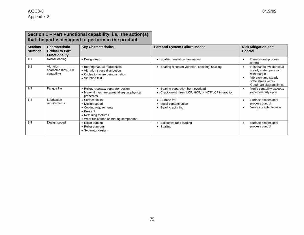
AC 33-8 8/19/09 Appendix 2
75
Section 1 – Part Functional capability, i.e., the action(s) that the part is designed to perform in the product Section/Number
Characteristic Critical to Part Functionality
Key Characteristics Part and System Failure Modes Risk Mitigation and Control
1-1 Radial loading • Design load • Spalling, metal contamination
• Dimensional process control
1-2 Vibration characteristics (HCF capability)
• Bearing natural frequencies • Vibration stress distribution • Cycles to failure demonstration • Vibration test
• Bearing resonant vibration, cracking, spalling • Resonance avoidance at steady state operation with margin
• Vibratory and steady state stress within Goodman diagram limits
1-3 Fatigue life • Roller, raceway, separator design • Material mechanical/metallurgical/physical
properties
• Bearing separation from overload • Crack growth from LCF, HCF, or HCF/LCF interaction
• Verify capability exceeds expected duty cycle
1-4 Lubrication requirements
• Surface finish • Design speed • Cooling requirements • Press fit • Retaining features • Wear resistance on mating component
• Surface fret • Metal contamination • Bearing spinning
• Surface dimensional process control
• Verify acceptable wear
1-5 Design speed • Roller loading • Roller diameter • Separator design
• Excessive race loading • Spalling
• Surface dimensional process control

AC 33-8 8/19/09 Appendix 2
76
Section 2 – Part Shape, size, dimensions and other physical measurable parameters, and interconnectivity with an engine integral part/systemSection/Number
Characteristic Critical to Part Functionality
Key Characteristics Part and System Failure Modes Risk Mitigation and Control
2-1 Boundary dimensions
• Inside diameter • Outside diameter • Oil hole size, location • Edge break
• Installation into engine
• Dimensional process control and inspection
2-2 Geometric dimensions
• Inner/outer runout • Inner/outer corner radii
• Vibration
• Dimensional process control
2-3 Anti-rotation features
• Thickness distribution • Edge breaks • Dampening features
• Vibratory mode changes • Bearing installation • Spinning
• Surface dimensional process control
2-4 Surface finish • Actual measurements of finish for all components of the bearing
• Vibration mode changes • Oil retention
• Dimensional process control
2-5 Fit-up dimensions • Radial play • Axial play • Face protrusion
• Vibration mode changes
• Dimensional process control and inspection
2-6 Internal geometry • Raceway radial roundness • Raceway waviness • Raceway curvature • Raceway shoulder height • Raceway straightness • Bearing-to-cage face clearance • Diametral cage land clearance • Roller grade • Ring wall thickness • Roller profile control parameters • Internal radial clearance (IRC)
• End loading • Scuffing • Spalling • Noisy
• Dimensional process control and inspection
2-7 Tolerance • Variance-fluctuations in measurements
• Mechanical/functional, failure due to variation from nominal • Verify part is tolerant to variation
• Control of manufacturing and inspection processes

AC 33-8 8/19/09 Appendix 2
77
Section 3 – Part Materials and Processes – Properties Section/Number
Characteristic Critical to Part Functionality
Key Characteristics Part and System Failure Modes Risk Mitigation and Control
3-1 Chemistry • Major elements - % variation • Impurities
• Poor mechanical or environmental properties • Material selection • Process control
3-2 Physical properties • Density • Coefficient of thermal expansion • Melting point
• Excessive weight • Excessive loading on retaining features
• Acceptable weight • Acceptable stresses • Hot/cold oil distress
3-3 Mechanical /metallurgical properties
• Modulus • Forging grain flow angles • Tensile, UTS, YS, elongation, stress
rupture, creep, LCF, HCF • Sudden overload properties • Surface hardness depth • Surface hardness
• Undesirable natural frequencies • Low material properties • Spalling during operation
• Acceptable stresses and frequencies
• Forging grain flow as required • Adequate material properties • Operational effects accounted for • Impact testing
3-4 Roller • Roller nominal diameter • Roller cylindricity • Roller length • Roller crown drop • Roller corner Radius
• Spalling • Vibration • Excess heat
• Process Control
3-5 Environmental resistance
• Oxidation, corrosion, fretting resistance • Elevated temperature stress relaxation • Surface plating
• Spalling from oxidation/corrosion pitting • Property reduction due to extreme oil overtemp or lack
of cooling oil
• Verify adequate environmental properties
Section 4 – Part Materials and Processes - Processing Section/ Number
Characteristic Critical to Part Functionality
Key Characteristics Part and System Failure Modes Risk Mitigation and Control
4-1 Raw material processing • Inclusions and porosity • Micro structural characteristics
• Crack growth from inclusion or porosity • Inadequate material properties
• Process control (melt control, cleanliness)
• Process control and sequencing
4-2 Heat treatment • Time @ temperature and ramp rates • Manufacturing sequence • Atmosphere • Tooling and fixturing
• Incorrect structure leading to low material properties
• Process control and sequencing
4-3 Surface treatment • Plating • Improper thickness and coverage • Process control 4-4 Peening • Intensity
• Coverage • Incorrect compressive stress, cracking • Process control

AC 33-8 8/19/09 Appendix 2
78
Section 4 – Part Materials and Processes - Processing Section/ Number
Characteristic Critical to Part Functionality
Key Characteristics Part and System Failure Modes Risk Mitigation and Control
4-5 Surface hardening • Time @ temperature and ramp rates • Manufacturing sequence • Atmosphere • Tooling and fixturing
• Improper case depth • Hardness improper
• Process control
4-6 Material removal – Non traditional (EDM, ECM, laser, water-jet, etc.)and conventional (machining, milling, broaching, grinding, blending, honing, lapping, stripping, etc.)
Micro cracks or recast: • Inherent to the process • Due to abusive machining
Fatigue capability degradation, due to: • Surface finish • Stress risers • Chemical attack
• Cracking initiation from micro-cracks or re-cast • Verify part is tolerant to proposed limits
• Process control
4-7 Non-destructive testing (NDT)
• Acceptance limits • Sensitivity
• Cracking from excessive defect size • Verify part is tolerant to allowable defects
4-8 Process sequencing and significant process identification and substantiation
• Inspection • Manufacturing • Process substantiation and control
(RSS,RSA,ESA, etc)
• Inadequate final part form, or defect “escape” • Verify adequate control of processes and parameters
Section 5 – Analysis Section/ Number
Characteristic Critical to Part Functionality
Key Characteristics Part and System Failure Modes Risk Mitigation and Control
5-1 Operating conditions • Torque loads • Oil temperatures • Speeds • Transient loads • Axial/radial loads
• Inadequate part life due to analysis under-predicting part temperature, mechanical stress
• Perform analysis at relevant operating conditions
5-2 LCF life assessment • Temperature effects • Overloads • FOD impact
• Inadequate part life due to analysis • Using incorrect properties • Failing to address the ‘key characteristics’
• Use applicable properties • Select mesh size to correctly
model the geometry 5-3 HCF life analysis • Temperature effects
• Vibration and mean stress effects • Resonant vibration, cracking • Use applicable properties and
Goodman diagram 5-4 Fracture mechanics • Temperature effects
• Threshold stress intensity • Crack growth from defect • Use applicable dA/dN curve
• Predict K using expected defect size
5-5 Variation • Engine operation characteristics • Inadequate part life due to variation • Verify part is tolerant to variation 5-6 Life calculation • Predicted stress and temperature
• Material properties • Operation during part life
• Inadequate part life due to analysis under-predicting • Verify correct inputs to lifing process

AC 33-8 8/19/09 Appendix 2
79
Section 6 – Testing
Section/ Number
Characteristic Critical to Part Functionality
Key Characteristics Part and System Failure Modes Risk Mitigation and Control
6-1 Durability • Fatigue • Tensile strength • Spalling • Engine vibration response • Microstructure
• Bearing surface breakdown • Perform adequate component and/or engine testing
6-2 Operability and performance
• Vibration signature • Abnormal wear • Maximum pad loading
• Excessive vibration • Metal particles in oil • Excessive oil temperature
• Engine testing
Section 7 – Potential Impact on Regulatory Requirements
Note: The regulatory requirements identified below, which are inclusive up to Amendment 20 of 14 CFR part 33, are intended as a guide to applicants when determining the applicable regulations to which they must show compliance. Those requirements listed as “Could be affected” highlight the regulations whose compliance findings are typically affected by the component or part that this template is addressing. This guide is not all-inclusive and the applicant remains responsible for identifying the certification basis of the product on which their PMA part is to be installed.
Applicable 14 CFR Part 33 Regulatory
Requirements Comments
Subpart A – General
1. 33.4 Instructions for Continued Airworthiness Could be affected ICAs including on-wing inspection requirements and on-wing limits for oil analysis
2. 33.5 Instruction manual for installing and operating the engine
3. 33.7 Engine ratings and operating limitations
4. 33.8 Selection of engine power and thrust ratings

AC 33-8 8/19/09 Appendix 2
80
Subpart B – Design and Construction;
General
5. 33.14 Start-stop cyclic stress (low cycle fatigue)
6. 33.15 Materials Could be affected
7. 33.17 Fire prevention
8. 33.19 Durability Could be affected
9. 33.21 Engine cooling
10. 33.23 Engine mounting attachments and structure
11. 33.25 Accessory attachments
12. 33.27 Turbine, compressor, fan, and turbo-supercharger rotors
13. 33.28 Electrical and electronic control systems
14. 33.29 Instrumentation connection
Subpart E – Design and Construction;
Turbine Aircraft Engines
15. 33.62 Stress analysis
16. 33.63 Vibration Could be affected Bearing vibration-Design
17. 33.65 Surge and stall characteristics
18. 33.66 Bleed air systems
19. 33.67 Fuel system
20. 33.68 Induction system icing (Operability aspects)
21. 33.69 Ignition system
22. 33.71 Lubrication system
23. 33.72 Hydraulic actuating system
24. 33.73 Power or thrust response
25. 33.74 Continued rotation Could be affected Continued integrity
26. 33.75 Safety analysis Could be affected Bearing/Gear/Shaft release

AC 33-8 8/19/09 Appendix 2
81
Subpart E – Design and Construction; Turbine Aircraft Engines
27. 33.76 Bird ingestion (Operability aspects of ingestion)
Could be affected Sudden bearing radial loading
28. 33.77 Foreign object ingestion (Operability aspects of ingestion)
Could be affected Sudden bearing radial loading
29. 33.78 Rain and hail ingestion
30. 33.79 Fuel burning thrust augmenter
Subpart F – Block Tests; Turbine Aircraft Engines
31. 33.83 Vibration test Could be affected Bearing vibration
32. 33.85 Calibration tests
33. 33.87 Endurance test Could be affected Bearing durability
34. 33.88 Engine over temperature test
35. 33.89 Operation test
36. 33.90 Initial maintenance inspection Could be affected Bearing in-service inspection limits
37. 33.91 Engine component tests
38. 33.92 Rotor locking tests
39. 33.93 Teardown inspection Could be affected Bearing wear must be within serviceable limits
40. 33.94 Blade containment and rotor unbalance tests (Weight changes)
41. 33.95 Engine-propeller system tests
42. 33.96 Engine tests in auxiliary power unit (APU) mode
43. 33.97 Thrust reversers
44. 33.99 General conduct of block tests
45. Part 33 - Appendix A – Instructions for Continued Airworthiness
Could be affected
46. Part 33 - Appendix B - Certification Standard Atmospheric Concentrations of Rain and Hail
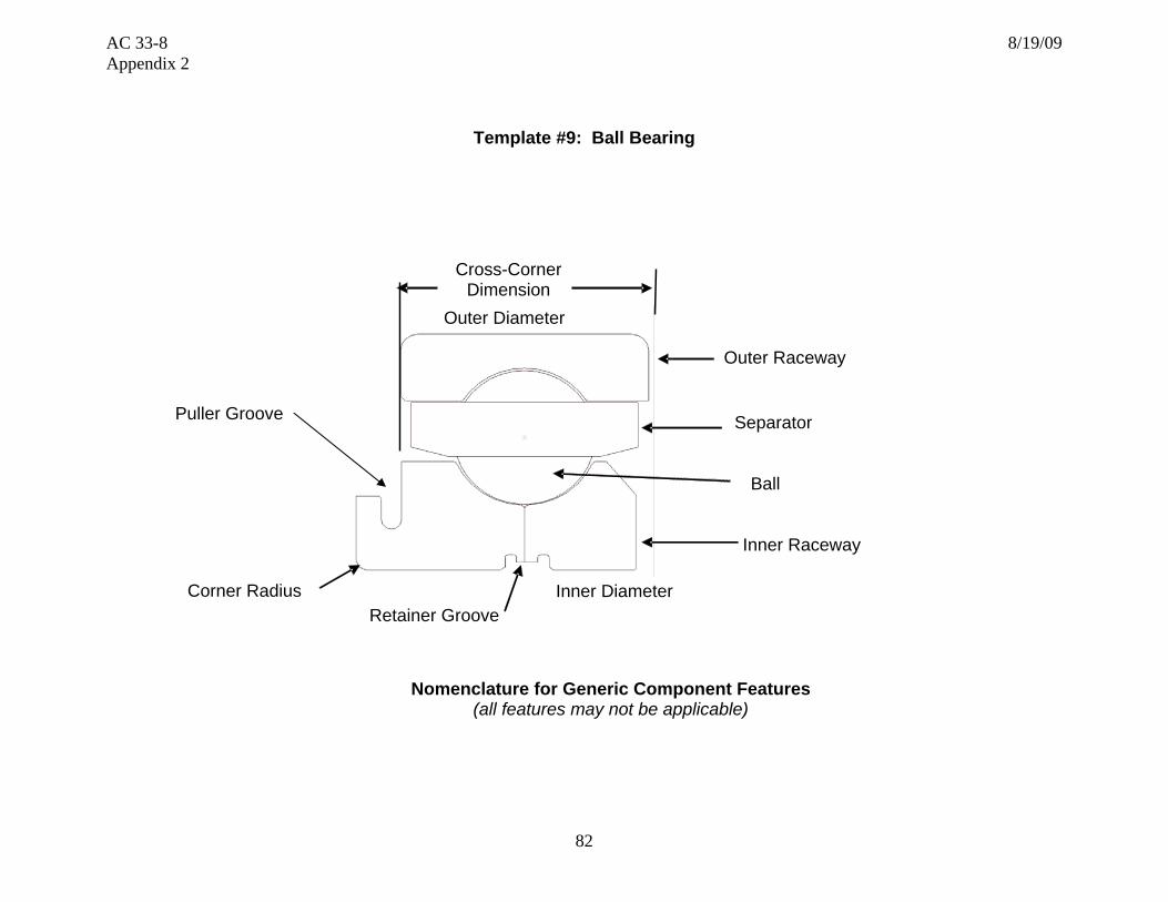
AC 33-8 8/19/09 Appendix 2
82
Template #9: Ball Bearing
Nomenclature for Generic Component Features
(all features may not be applicable)
Puller Groove
Retainer Groove
Outer Raceway
Separator
Ball
Corner Radius
Inner Raceway
Outer Diameter
Inner Diameter
Cross-CornerDimension

AC 33-8 8/19/09 Appendix 2
83
Section 1 – Part Functional capability, i.e., the action(s) that the part is designed to perform in the product Section/Number
Characteristic Critical to Part Functionality
Key Characteristics Part and System Failure Modes Risk Mitigation and Control
1-1 Radial loading • Design load • Spalling, metal contamination
• Dimensional process control
1-2 Axial loading • Design load • Spalling, metal contamination • Dimensional control
1-3 Vibration characteristics (HCF capability)
• Bearing natural frequencies • Vibration stress distribution • Cycles to failure demonstration • Vibration test
• Bearing resonant vibration, cracking, spalling • Resonance avoidance at steady state operation with margin
• Vibratory and steady state stress within Goodman diagram limits
1-4 Fatigue life • Ball, raceway, separator design • Material mechanical/metallurgical/physical
properties
• Bearing separation from overload • Crack growth from LCF, HCF, or HCF/LCF interaction
• Verify capability exceeds expected duty cycle
1-5 Lubrication requirements
• Surface finish • Design speed • Cooling requirements • Press fit • Retaining features • Wear resistance on mating component
• Surface fret • Metal contamination • Bearing spinning
• Surface dimensional process control
• Verify acceptable wear
1-6 Design speed • Ball loading • Ball diameter • Separator design
• Excessive race loading • Spalling
• Surface dimensional process control

AC 33-8 8/19/09 Appendix 2
84
Section 2 – Part Shape, size, dimensions and other physical measurable parameters, and interconnectivity with an engine integral part/systemSection/Number
Characteristic Critical to Part Functionality
Key Characteristics Part and System Failure Modes Risk Mitigation and Control
2-1 Boundary dimensions
• Inside diameter • Outside diameter • Oil hole size, location • Edge break
• Installation into engine
• Dimensional process control and inspection
2-2 Geometric dimensions
• Inner/outer runout • Inner/outer corner radii
• Vibration
• Dimensional process control
2-3 Anti-rotation features
• Thickness distribution • Edge breaks • Dampening features
• Vibratory mode changes • Bearing installation • Spinning
• Surface dimensional process control
2-4 Surface finish • Actual measurements of finish for all components of the bearing
• Vibration mode changes • Oil retention
• Dimensional process control
2-5 Fit-up dimensions • Radial play • Axial play • Contact angle • Face protrusion
• Vibration mode changes
• Dimensional process control and inspection
2-6 Internal geometry • Raceway radial roundness • Raceway waviness • Raceway curvature • Raceway shoulder height • Bearing-to-cage face clearance • Diametral cage land clearance • Ball grade • Ring wall thickness • Internal radial clearance
• End loading • Scuffing • Spalling • Noisy
• Dimensional process control and inspection
2-7 Tolerance • Variance-fluctuations in measurements
• Mechanical/Functional, failure due to variation from nominal
• Verify part is tolerant to variation
• Control of manufacturing and inspection processes
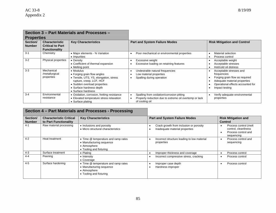
AC 33-8 8/19/09 Appendix 2
85
Section 3 – Part Materials and Processes – Properties Section/Number
Characteristic Critical to Part Functionality
Key Characteristics Part and System Failure Modes Risk Mitigation and Control
3-1 Chemistry • Major elements - % Variation • Impurities
• Poor mechanical or environmental properties • Material selection • Process control
3-2 Physical properties • Density • Coefficient of thermal expansion • Melting point
• Excessive weight • Excessive loading on retaining features
• Acceptable weight • Acceptable stresses • Hot/cold oil distress
3-3 Mechanical /metallurgical properties
• Modulus • Forging grain flow angles • Tensile, UTS, YS, elongation, stress
rupture, creep, LCF, HCF • Sudden overload properties • Surface hardness depth • Surface hardness
• Undesirable natural frequencies • Low material properties • Spalling during operation
• Acceptable stresses and frequencies
• Forging grain flow as required • Adequate material properties • Operational effects accounted for • Impact testing
3-4 Environmental resistance
• Oxidation, corrosion, fretting resistance • Elevated temperature stress relaxation • Surface plating
• Spalling from oxidation/corrosion pitting • Property reduction due to extreme oil overtemp or lack
of cooling oil
• Verify adequate environmental properties
Section 4 – Part Materials and Processes - Processing Section/ Number
Characteristic Critical to Part Functionality
Key Characteristics Part and System Failure Modes Risk Mitigation and Control
4-1 Raw material processing • Inclusions and porosity • Micro structural characteristics
• Crack growth from inclusion or porosity • Inadequate material properties
• Process control (melt control, cleanliness
• Process control and sequencing
4-2 Heat treatment • Time @ temperature and ramp rates • Manufacturing sequence • Atmosphere • Tooling and fixturing
• Incorrect structure leading to low material properties
• Process control and sequencing
4-3 Surface treatment • Plating • Improper thickness and coverage • Process control 4-4 Peening • Intensity
• Coverage • Incorrect compressive stress, cracking • Process control
4-5 Surface hardening • Time @ temperature and ramp rates • Manufacturing sequence • Atmosphere • Tooling and fixturing
• Improper case depth • Hardness improper
• Process control

AC 33-8 8/19/09 Appendix 2
86
Section 4 – Part Materials and Processes - Processing Section/ Number
Characteristic Critical to Part Functionality
Key Characteristics Part and System Failure Modes Risk Mitigation and Control
4-6 Material removal – Non traditional (EDM, ECM, laser, water-jet, etc.)and conventional (machining, milling, broaching, grinding, blending, honing, lapping, stripping, etc.)
Micro cracks or recast: • Inherent to the process • Due to abusive machining
Fatigue capability degradation, due to: • Surface finish • Stress risers • Chemical attack
• Cracking initiation from micro-cracks or re-cast • Verify part is tolerant to proposed limits
• Process control
4-7 Non-destructive testing (NDT)
• Acceptance limits • Sensitivity
• Cracking from excessive defect size • Verify part is tolerant to allowable defects
4-8 Process sequencing and significant process identification and substantiation
• Inspection • Manufacturing • Process substantiation and control
(RSS,RSA,ESA, etc)
• Inadequate final part form, or defect “escape” • Verify adequate control of processes and parameters
Section 5 – Analysis Section/ Number
Characteristic Critical to Part Functionality
Key Characteristics Part and System Failure Modes Risk Mitigation and Control
5-1 Operating conditions • Torque loads • Oil temperatures • Speeds • Transient loads • Axial/radial loads
• Inadequate part life due to analysis under-predicting part temperature, mechanical stress
• Perform analysis at relevant operating conditions
5-2 LCF life assessment • Temperature effects • Overloads • FOD impact
• Inadequate part life due to analysis • Using incorrect properties • Failing to address the ‘key characteristics’
• Use applicable properties • Select mesh size to correctly
model the geometry 5-3 HCF life analysis • Temperature effects
• Vibration and mean stress effects • Resonant vibration, cracking • Use applicable properties and
Goodman diagram 5-4 Fracture mechanics • Temperature effects
• Threshold stress intensity • Crack growth from defect • Use applicable dA/dN curve
• Predict K using expected defect size
5-5 Variation • Engine operation characteristics • Inadequate part life due to variation • Verify part is tolerant to variation 5-6 Life calculation • Predicted stress and temperature
• Material properties • Operation during part life
• Inadequate part life due to analysis under-predicting • Verify correct inputs to lifing process

AC 33-8 8/19/09 Appendix 2
87
Section 6 – Testing
Section/ Number
Characteristic Critical to Part Functionality
Key Characteristics Part and System Failure Modes Risk Mitigation and Control
6-1 Durability • Fatigue • Tensile strength • Spalling • Engine vibration response • Microstructure
• Bearing surface breakdown • Perform adequate component and/or engine testing
6-2 Operability and performance
• Vibration signature • Abnormal wear • Maximum pad loading
• Excessive vibration • Metal particles in oil • Excessive oil temperature
• Engine testing
Section 7 – Potential Impact on Regulatory Requirements
Note: The regulatory requirements identified below, which are inclusive up to Amendment 20 of 14 CFR part 33, are intended as a guide to applicants when determining the applicable regulations to which they must show compliance. Those requirements listed as “Could be affected” highlight the regulations whose compliance findings are typically affected by the component or part that this template is addressing. This guide is not all-inclusive and the applicant remains responsible for identifying the certification basis of the product on which their PMA part is to be installed.
Applicable 14 CFR Part 33 Regulatory
Requirements Comments
Subpart A – General
1. 33.4 Instructions for Continued Airworthiness Could be affected ICAs including on-wing inspection requirements and on-wing limits for oil analysis
2. 33.5 Instruction manual for installing and operating the engine
3. 33.7 Engine ratings and operating limitations
4. 33.8 Selection of engine power and thrust ratings

AC 33-8 8/19/09 Appendix 2
88
Subpart B – Design and Construction;
General
5. 33.14 Start-stop cyclic stress (low cycle fatigue)
6. 33.15 Materials Could be affected
7. 33.17 Fire prevention
8. 33.19 Durability Could be affected
9. 33.21 Engine cooling
10. 33.23 Engine mounting attachments and structure
11. 33.25 Accessory attachments
12. 33.27 Turbine, compressor, fan, and turbo-supercharger rotors
13. 33.28 Electrical and electronic control systems
14. 33.29 Instrumentation connection
Subpart E – Design and Construction;
Turbine Aircraft Engines
15. 33.62 Stress analysis
16. 33.63 Vibration Could be affected Bearing vibration-Design
17. 33.65 Surge and stall characteristics
18. 33.66 Bleed air systems
19. 33.67 Fuel system
20. 33.68 Induction system icing (Operability aspects)
21. 33.69 Ignition system
22. 33.71 Lubrication system
23. 33.72 Hydraulic actuating system
24. 33.73 Power or thrust response
25. 33.74 Continued rotation Could be affected Continued integrity
26. 33.75 Safety analysis Could be affected Bearing/Gear/Shaft release

AC 33-8 8/19/09 Appendix 2
89
Subpart E – Design and Construction; Turbine Aircraft Engines
27. 33.76 Bird ingestion (Operability aspects of ingestion)
Could be affected Sudden bearing axial/radial loading
28. 33.77 Foreign object ingestion (Operability aspects of ingestion)
Could be affected Sudden bearing axial/radial loading
29. 33.78 Rain hail ingestion
30. 33.79 Fuel burning thrust augmenter
Subpart F – Block Tests; Turbine Aircraft Engines
31. 33.83 Vibration test Could be affected Bearing vibration
32. 33.85 Calibration tests
33. 33.87 Endurance test Could be affected Bearing durability
34. 33.88 Engine over temperature test
35. 33.89 Operation test
36. 33.90 Initial maintenance inspection Could be affected Bearing in-service inspection limits
37. 33.91 Engine component tests
38. 33.92 Rotor locking tests
39. 33.93 Teardown inspection Could be affected Bearing wear must be within serviceable limits
40. 33.94 Blade containment and rotor unbalance tests (Weight changes)
41. 33.95 Engine-propeller system tests
42. 33.96 Engine tests in auxiliary power unit (APU) mode
43. 33.97 Thrust reversers
44. 33.99 General conduct of block tests
45. Part 33 - Appendix A – Instructions for Continued Airworthiness
Could be affected
46. Part 33 - Appendix B - Certification Standard Atmospheric Concentrations of Rain and Hail

AC 33-8 8/19/09 Appendix 2
90
Template #10: Gear
Nomenclature for Generic Component Features
(all features may not be applicable)
Gear Teeth Rim
Bearing Mount
Threaded Retention Feature
Bearing Stop
Lightening Holes Hub
Web

AC 33-8 8/19/09 Appendix 2
91
Section 1 – Part Functional capability, i.e., the action(s) that the part is designed to perform in the product Section/Number
Characteristic Critical to Part Functionality
Key Characteristics Part and System Failure Modes Risk Mitigation and Control
1-1 Weight • As-forged surfaces • Machined surfaces
• Bearing loading • Inertia
• Surface dimensional process control
1-2 Gear tooth geometry • Number of teeth • Gear tooth form • Surface finish • Surface hardness
• Correct speed • Heat generation • Metal generation
• Dimensional control • Machining process
control
1-3 Vibration characteristics (HCF capability)
• Gear natural frequencies • Vibration stress distribution • Cycles to failure demonstration • Vibration test
• Gear resonant vibration, cracking • Resonance avoidance at steady state operation with margin
• Vibratory and steady state stress within Goodman diagram limits
1-4 LCF, fracture toughness, tensile overload capability
• Tooth/web geometry • Material mechanical/metallurgical/physical
properties
• Tooth separation from overload • Crack growth from LCF, HCF, or HCF/LCF interaction
• Verify capability exceeds expected duty cycle for highest load application
1-5 Bearing attachment • Surface finish • Press fit • Retaining thread • Wear resistance on mating component
• Surface fret • Metal contamination • Bearing spinning
• Surface dimensional process control
• Verify acceptable wear
1-6 Weight reduction • Hole size and location • Distance from hub and rim • Surface finish
• Excessive tip cracking or corner loss • Surface dimensional process control

AC 33-8 8/19/09 Appendix 2
92
Section 2 – Part Shape, size, dimensions and other physical measurable parameters, and interconnectivity with an engine integral part/systemSection/Number
Characteristic Critical to Part Functionality
Key Characteristics Part and System Failure Modes Risk Mitigation and Control
2-1 Tooth form • Shape • Surface finish • Pitch diameter • Contact angle • Edge break • Tolerance
• Unbalance loading • Vibration • End loading • Scuffing
• Dimensional process control and inspection
2-2 Gear rim • Width • Height
• Width: proper transition radius • Height: enough mass to control deformation • Rim resonant vibration, cracking, dysfunction
• Dimensional process control
2-3 Web • Transition to rim and hub • Thickness distribution • Lightning features • Dampening features
• Gear vibratory mode changes due to thickness distribution • Weight – excessive inertia load • Stress/life
• Surface dimensional process control
2-4 Hub • Bearing fit • Axial location of gear surface
• Proper bearing preload • Correct gear alignment
• Dimensional process control
2-5 Tolerance • Variance-fluctuations in measurements • Measurement gauge repeatability and
reliability
• Mechanical/functional, failure due to variation from nominal • Verify part is tolerant to variation
• Control of manufacturing and inspection processes
Section 3 – Part Materials and Processes – Properties Section/Number
Characteristic Critical to Part Functionality
Key Characteristics Part and System Failure Modes Risk Mitigation and Control
3-1 Chemistry • Major elements - % variation • Impurities
• Poor mechanical or environmental properties • Material selection • Process control
3-2 Physical properties • Density • Coefficient of thermal expansion • Melting point
• Excessive weight • Excessive loading on retaining features
• Acceptable gear weight • Acceptable stresses • Hot/cold oil distress
3-3 Mechanical /metallurgical properties
• Modulus • Forging grain flow angles • Tensile, UTS, YS, elongation, stress rupture,
creep, LCF, HCF • Sudden overload properties • Surface hardness depth
• Undesirable natural frequencies • Low material properties: tooth, rim separation • Spalling during operation
• Acceptable stresses & frequencies • Forging grain flow as required • Adequate material properties • Operational effects accounted for • Impact testing
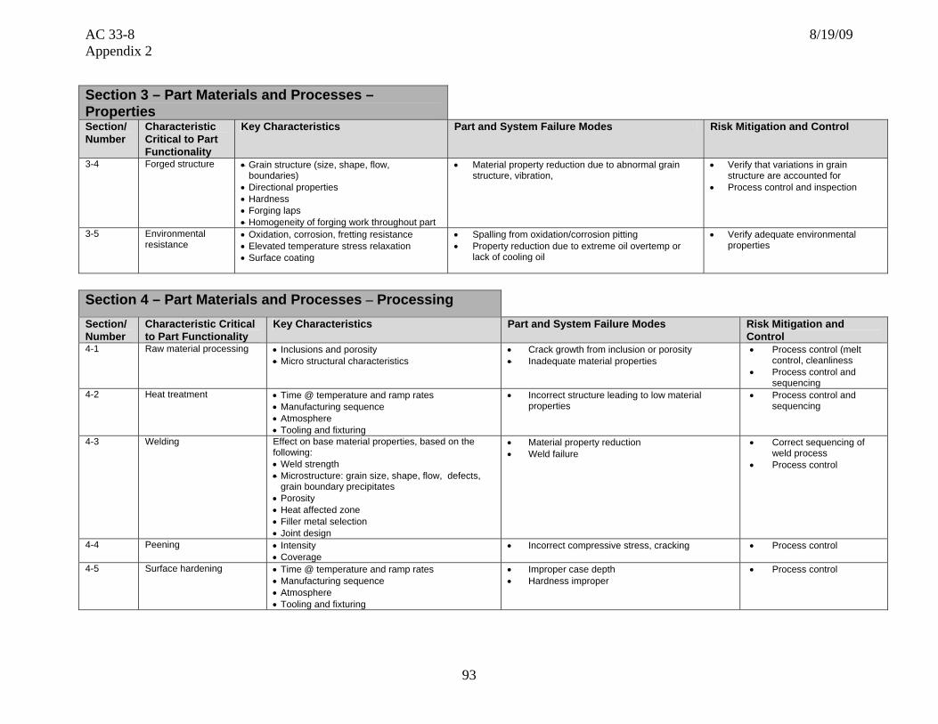
AC 33-8 8/19/09 Appendix 2
93
Section 3 – Part Materials and Processes – Properties Section/Number
Characteristic Critical to Part Functionality
Key Characteristics Part and System Failure Modes Risk Mitigation and Control
3-4 Forged structure • Grain structure (size, shape, flow, boundaries)
• Directional properties • Hardness • Forging laps • Homogeneity of forging work throughout part
• Material property reduction due to abnormal grain structure, vibration,
• Verify that variations in grain structure are accounted for
• Process control and inspection
3-5 Environmental resistance
• Oxidation, corrosion, fretting resistance • Elevated temperature stress relaxation • Surface coating
• Spalling from oxidation/corrosion pitting • Property reduction due to extreme oil overtemp or
lack of cooling oil
• Verify adequate environmental properties
Section 4 – Part Materials and Processes – Processing Section/ Number
Characteristic Critical to Part Functionality
Key Characteristics Part and System Failure Modes Risk Mitigation and Control
4-1 Raw material processing • Inclusions and porosity • Micro structural characteristics
• Crack growth from inclusion or porosity • Inadequate material properties
• Process control (melt control, cleanliness
• Process control and sequencing
4-2 Heat treatment • Time @ temperature and ramp rates • Manufacturing sequence • Atmosphere • Tooling and fixturing
• Incorrect structure leading to low material properties
• Process control and sequencing
4-3 Welding Effect on base material properties, based on the following: • Weld strength • Microstructure: grain size, shape, flow, defects,
grain boundary precipitates • Porosity • Heat affected zone • Filler metal selection • Joint design
• Material property reduction • Weld failure
• Correct sequencing of weld process
• Process control
4-4 Peening • Intensity • Coverage
• Incorrect compressive stress, cracking • Process control
4-5 Surface hardening • Time @ temperature and ramp rates • Manufacturing sequence • Atmosphere • Tooling and fixturing
• Improper case depth • Hardness improper
• Process control

AC 33-8 8/19/09 Appendix 2
94
Section 4 – Part Materials and Processes – Processing Section/ Number
Characteristic Critical to Part Functionality
Key Characteristics Part and System Failure Modes Risk Mitigation and Control
4-6 Material removal – Non traditional (EDM, ECM, laser, water-jet, etc.) and conventional (machining, milling, broaching, grinding, blending, honing, lapping, stripping, etc.)
Micro cracks or recast: • Inherent to the process • Due to abusive machining
Fatigue capability degradation, due to: • Surface finish • Stress risers • Chemical attack
• Cracking initiation from micro-cracks or re-cast • Verify part is tolerant to proposed limits
• Process control
4-7 Non-destructive testing (NDT)
• Acceptance limits • Sensitivity
• Cracking from excessive defect size • Verify part is tolerant to allowable defects
4-8 Process sequencing and significant process identification and substantiation
• Inspection • Manufacturing • Process substantiation and control
(RSS,RSA,ESA, etc)
• Inadequate final part form, or defect “escape” • Verify adequate control of processes and parameters
4-9 Forging process Forging structure • Grain structure (size, shape, flow, boundaries) • Directional properties • Hardness • Forging laps • Homogeneity of forging work throughout part
• Material property reduction due to abnormal grain structure
• Process control and sequencing
Section 5 – Analysis Section/ Number
Characteristic Critical to Part Functionality
Key Characteristics Part and System Failure Modes Risk Mitigation and Control
5-1 Operating conditions • Torque loads • Oil temperatures • Speeds • Transient loads
• Inadequate part life due to analysis under-predicting part temperature, mechanical stress
• Perform analysis at relevant operating conditions
5-2 LCF life assessment • Temperature effects • Overloads • FOD impact
• Inadequate part life due to analysis • Using incorrect properties • Failing to address the ‘key characteristics’
• Use applicable properties • Select mesh size to correctly
model the geometry 5-3 HCF life analysis • Temperature effects
• Vibration and mean stress effects
• Resonant vibration, cracking, dysfunction • Use applicable properties and Goodman diagram
5-4 Fracture mechanics • Temperature effects • Threshold stress intensity
• Crack growth from defect • Use applicable dA/dN curve • Predict K using expected defect
size

AC 33-8 8/19/09 Appendix 2
95
Section 5 – Analysis Section/ Number
Characteristic Critical to Part Functionality
Key Characteristics Part and System Failure Modes Risk Mitigation and Control
5-6 Variation • Engine operation characteristics
• Inadequate part life due to variation • Verify part is tolerant to variation
5-7 Life calculation • Predicted stress and Temperature
• Material properties • Operation during part life
• Inadequate part life due to analysis under-predicting • Verify correct inputs to lifing process
Section 6 – Testing
Section/Number Characteristic Critical to Part Functionality
Key Characteristics Part and System Failure Modes Risk Mitigation and Control
6-1 Durability • Fatigue • Tensile strength • Tooth alignment • Spalling • Engine vibration response • Microstructure
• Gear dysfunction • Perform adequate component and/or engine testing
6-2 Operability and performance
• Vibration signature • Abnormal gear wear • Maximum pad loading
• Excessive vibration • Metal particles in oil • Accessories not able to be fully loaded
• Engine testing

AC 33-8 8/19/09 Appendix 2
96
Section 7 – Potential Impact on Regulatory Requirements
Note: The regulatory requirements identified below, which are inclusive up to Amendment 20 of 14 CFR part 33, are intended as a guide to applicants when determining the applicable regulations to which they must show compliance. Those requirements listed as “Could be affected” highlight the regulations whose compliance findings are typically affected by the component or part that this template is addressing. This guide is not all-inclusive and the applicant remains responsible for identifying the certification basis of the product on which their PMA part is to be installed.
Applicable 14 CFR Part 33 Regulatory
Requirements Comments
Subpart A – General
1. 33.4 Instructions for Continued Airworthiness Could be affected ICAs including on-wing inspection requirements and on-wing limits
2. 33.5 Instruction manual for installing and operating the engine
3. 33.7 Engine ratings and operating limitations
4. 33.8 Selection of engine power and thrust ratings
Subpart B – Design and Construction; General
5. 33.14 Start-stop cyclic stress (low cycle fatigue)
6. 33.15 Materials Could be affected
7. 33.17 Fire prevention
8. 33.19 Durability Could be affected
9. 33.21 Engine cooling
10. 33.23 Engine mounting attachments and structure
11. 33.25 Accessory attachments
12. 33.27 Turbine, compressor, fan, and turbo-supercharger rotors
13. 33.28 Electrical and electronic control systems
14. 33.29 Instrumentation connection

AC 33-8 8/19/09 Appendix 2
97
Subpart E – Design and Construction: Turbine Aircraft Engines
15. 33.62 Stress analysis
16. 33.63 Vibration Could be affected Gear vibration-Design
17. 33.65 Surge and stall characteristics
18. 33.66 Bleed air systems
19. 33.67 Fuel system
20. 33.68 Induction system icing (Operability aspects)
21. 33.69 Ignition system
22. 33.71 Lubrication system
23. 33.72 Hydraulic actuating system
24. 33.73 Power or thrust response Could be affected Gear train response
25. 33.74 Continued rotation Could be affected Continued integrity
26. 33.75 Safety analysis Could be affected Gear release
27. 33.76 Bird ingestion (Operability aspects of ingestion)
Could be affected Sudden gear train loading
28. 33.77 Foreign object ingestion (Operability aspects of ingestion)
Could be affected Sudden gear train loading
29. 33.78 Rain and hail ingestion
30. 33.79 Fuel burning thrust augmenter
Subpart F – Block Tests; Turbine Aircraft Engines
31. 33.83 Vibration test Could be affected Gear vibration
32. 33.85 Calibration tests
33. 33.87 Endurance test Could be affected Gear durability
34. 33.88 Engine over temperature test
35. 33.89 Operation test

AC 33-8 8/19/09 Appendix 2
98
Subpart F – Block Tests; Turbine Aircraft Engines
36. 33.90 Initial maintenance inspection Could be affected Gear in-service inspection limits
37. 33.91 Engine component tests
38. 33.92 Rotor locking tests
39. 33.93 Teardown inspection Could be affected Gear wear must be within serviceable limits
40. 33.94 Blade containment and rotor unbalance tests (Weight changes)
41. 33.95 Engine-propeller system tests
42. 33.96 Engine tests in auxiliary power unit (APU) mode
43. 33.97 Thrust reversers
44. 33.99 General conduct of block tests
45. Part 33 - Appendix A – Instructions for Continued
Airworthiness Could be affected
46. Part 33 - Appendix B - Certification Standard Atmospheric Concentrations of Rain and Hail
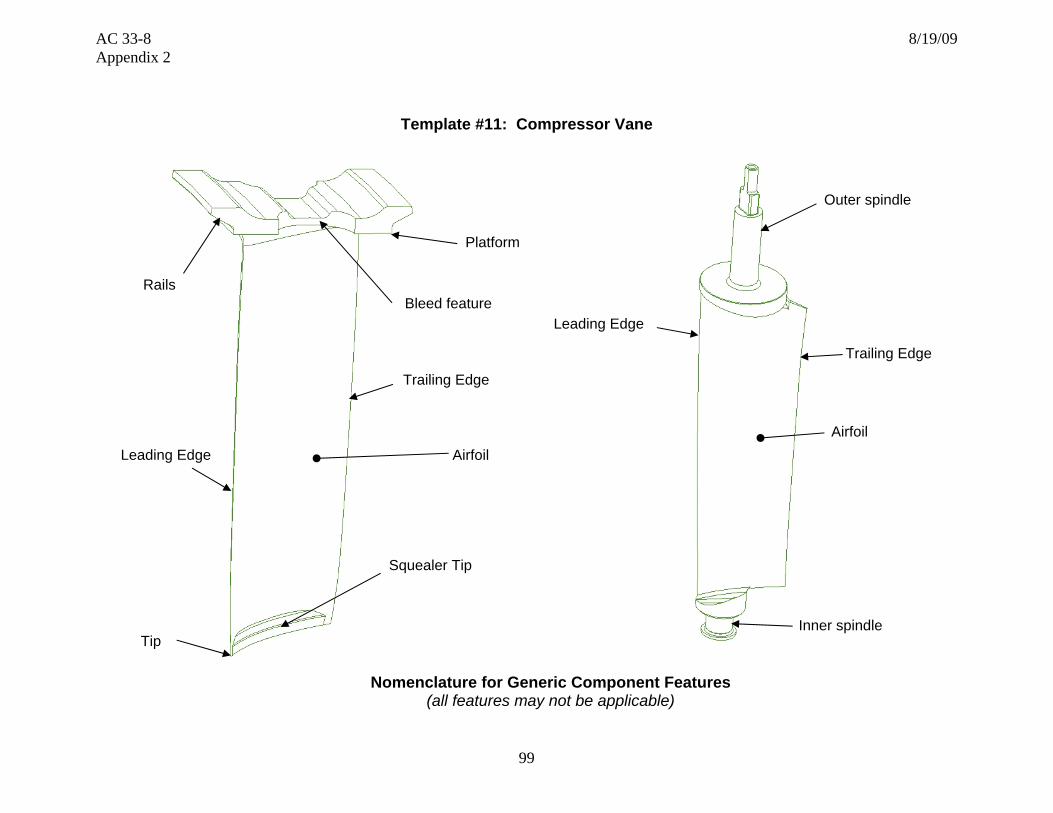
AC 33-8 8/19/09 Appendix 2
99
Template #11: Compressor Vane
Nomenclature for Generic Component Features (all features may not be applicable)
Tip
Squealer Tip
Airfoil
Trailing Edge
Platform
Bleed feature
Leading Edge
Rails
Outer spindle
Inner spindle
Airfoil
Trailing Edge
Leading Edge

AC 33-8 8/19/09 Appendix 2
100
Section 1 – Part Functional capability, i.e., the action(s) that the part is designed to perform in the product Section/Number
Characteristic Critical to Part Functionality
Key Characteristics Part and System Failure Modes Risk Mitigation and Control
1-1 Vibration damping Vane rail to case clearance Vane vibration: Vane or case cracking or wear Control vane attachment to case clearance
1-2 Vibration characteristics (HCF capability)
• Vane natural frequencies • Vibration stress distribution • Cycles to failure demonstration • Vibration test set-up and execution criteria, i.e.,
establishing parameters for vane holding, loading, excitation modes determination, and excitation sensing techniques
Vane resonant vibration, cracking, dysfunction Resonance avoidance at steady state operation with margin Vibratory and steady state stress within Goodman diagram limits
1-3 LCF, fracture toughness, tensile overload capability
• Vane geometry • Material mechanical/metallurgical/physical
properties
• Vane separation from tensile overload • Crack growth from LCF, HCF, or HCF/LCF interaction • Loss of tip fatigue strength from rubbing
Verify capability exceeds expected utilization
1-4 Squealer tip • Squealer tip geometry • Excessive rub load • Tip cracking or corner loss
Surface dimensional process control
Section 2 – Part Shape, size, dimensions and other physical measurable parameters, and interconnectivity with an engine integral part/system Section/Number
Characteristic Critical to Part Functionality
Key Characteristics Part and System Failure Modes Risk Mitigation and Control
2-1 Rail/T-slot • Shape • Contour • Location relative to airfoil • Tolerance (vane root and case slot dimensional
spectrums and blade producibility limitations)
• Unbalance tang loading/blade dysfunction • Incorrect loading on disk/cracking • Inability to assemble • Excessive clearance/movement leading to vibration and
wear • Rotor to stator contact
Dimensional process control and inspection
2-2 Platform • Width - tangential • Length • Outer gas path contour
• Width: binding, recirculation • Length: rotor/stator rubs • Platform resonant vibration, cracking, dysfunction
Dimensional process control
2-3 Bleed off-take • Orifice size • Flow characteristics • Radial location on airfoil where applicable
• Inadequate cooling leading to turbine blade dysfunction • Incorrect customer bleed • Poor operability (TBV)
Dimensional process control

AC 33-8 8/19/09 Appendix 2
101
Section 2 – Part Shape, size, dimensions and other physical measurable parameters, and interconnectivity with an engine integral part/system Section/Number
Characteristic Critical to Part Functionality
Key Characteristics Part and System Failure Modes Risk Mitigation and Control
2-4 Airfoil external shape
• Aero contour/stagger angle • Leading edge contour • Thickness distribution • Chord
• Poor aero performance • Airfoil vibratory mode changes due to thickness distribution • Operability issues – stall leading to lack of thrust and
potential damage to flowpath hardware • FOD tolerance • Supply bleed pressure – turbine blade/rotor dysfunction • Airfoil stress/life
Surface dimensional process control
2-5 Airfoil wall thickness
Thickness vs chord and span • Airfoil stress/life Dimensional process control
2-6 Airfoil internal cavities
• Passage area and blockage • Inadequate cooling leading to turbine blade dysfunction • Incorrect customer bleed • Poor operability (TBV)
Dimensional process control and inspection of passage geometry
2-7 Tolerance • Variance-fluctuations in measurements • Measurement gauge repeatability and reliability
Mechanical/Functional, failure due to variation from nominal Verify part is tolerant to variation Control of manufacturing and inspection processes
2-8 Trunnions/spindles • Shape • Location relative to airfoil • Alignment of inner/outer trunnions • Indexing feature location relative to airfoil • Threaded feature and/or insert
• Inability to assemble • Excessive clearance/movement leading to vibration and
wear • Excessive drag and bushing wear • Rotor to stator contact • Incorrect VSV staging leading to airfoil dysfunction or
operability or performance issues
Dimensional process control and inspection
2-9 Airfoil to platform filets
• Filet profile • Failure due to stress concentration Dimensional process control

AC 33-8 8/19/09 Appendix 2
102
Section 3 – Part Materials and Processes – Properties Section/Number
Characteristic Critical to Part Functionality
Key Characteristics Part and System Failure Modes Risk Mitigation and Control
3-1 Chemistry • Major elements - % variation • Impurities
• Poor mechanical or environmental properties Material selection Process control
3-2 Physical properties • Density • Coefficient of thermal expansion • Melting Point
• Interference with surrounding hardware Verify: • Acceptable stresses • Vane “fit” in hot condition
3-3 Mechanical /metallurgical properties
• Modulus • Forging grain flow angles • Bare and coated: tensile (UTS, YS,
elongation, stress rupture, creep, LCF, HCF)
• Long term metallurgical stability • Impact properties
• Undesirable natural frequencies • Low material properties, vane dysfunction • Material capability consumed in operation
Verify: • Acceptable stresses & frequencies • Forging grain flow, as required • Adequate material properties • Operational effects accounted for Impact testing
3-4 Forged structure • Grain structure (size, shape, flow, boundaries
• Directional properties • Hardness • Forging laps • Homogeneity of forging work throughout
part
• Material property reduction due to abnormal grain structure, Vane dysfunction
Verify that grain structure are accounted for Process control & inspection
3-5 Environmental resistance
• Oxidation, corrosion, erosion, fretting resistance
• Elevated temperature stress relaxation, alpha case formation)
• Rubbing, FOD resistance
• Cracking from oxidation/corrosion pitting, vane dysfunction • Property reduction due to brittle Alpha case, vane
dysfunction
Verify adequate environmental properties
3-6 Environmental coating
• Coverage and thickness • Long term stability • Corrosion resistance
• Cracking from corrosion pitting Control of chemistry and application process Verify thermal-mechanical compatibility with base material
3-7 Ti Fire resistance • Rub rate (clearances, relative motion) • Environment (température, pressure) • Material of adjacent hardware
3-8 Rail/T-slot/trunnion wear coating
• Wear resistance and abrasiveness • Coverage and thickness • Temperature capability
Loss of material leading to dysfunction of vane and/or case Verify acceptable wear couple Control of chemistry and application process Verify adequate temperature capability
3-9 Erosion coating • Erosion resistance • Compatibility with base material
• Performance and operability degradation • Vane dysfunction due to material property degradation
Verify adequate erosion characteristics and base material compatibility

AC 33-8 8/19/09 Appendix 2
103
Section 4 – Part Materials and Processes - Processing Section/ Number
Characteristic Critical to Part Functionality
Key Characteristics Part and System Failure Modes Risk Mitigation and Control
4-1 Raw material processing • Inclusions and porosity • Microstructural characteristics
• Crack growth from inclusion or porosity • Inadequate material properties and vane blade
dysfunction
Process control (melt control, cleanliness) Process control and sequencing
4-2 Heat treatment • Time @ temperature and ramp rates • Manufacturing sequence • Atmosphere
Incorrect structure leading to low material properties
Process control and sequencing
4-3 Welding and brazing Effect on base material properties, based on the following: • Weld or braze strength • Microstructure (grain size, shape, flow, braze
gap, defects, grain boundary precipitate) • Porosity • Diffusion zone (brazing) • Heat affected zone (welding) • Penetration (welding) • Excess braze allowance • Filler metal selection
• Material property reduction • Braze or weld failure leading to separation of
vane assembly
Correct sequencing of braze or weld cycles in the process Process control
4-4 Peening • Intensity • Coverage
Incorrect rail/T-slot/trunnion compressive stress, cracking, vane dysfunction
Process control
4-5 Material removal – Non traditional (EDM, ECM, laser, water-jet, etc.)and conventional (machining, milling, broaching, grinding, blending, honing, lapping, stripping, etc.)
Micro cracks or recast: • Inherent to the process • Due to abusive machining Fatigue capability degradation, due to: • Surface finish • Stress risers • Chemical attack
Cracking initiation from micro-cracks or re-cast Verify part is tolerant to proposed limits Process control
4-6 Non-destructive testing (NDT)
• Acceptance limits • Sensitivity
Cracking from excessive defect size Verify part is tolerant to allowable defects
4-7 Process sequencing and significant process identification and substantiation
• Inspection • Manufacturing • Process substantiation and control
(RSS,RSA,ESA, etc)
Inadequate final part form, or defect “escape”, vane dysfunction
Verify adequate control of processes and parameters
4-8 Forging process Forging structure: • Grain Structure (size, shape, flow, boundaries) • Directional properties • Hardness • Forging laps • Homogeneity of forging work throughout part
Material property reduction due to abnormal grain structure, vane dysfunction
Process control and sequencing
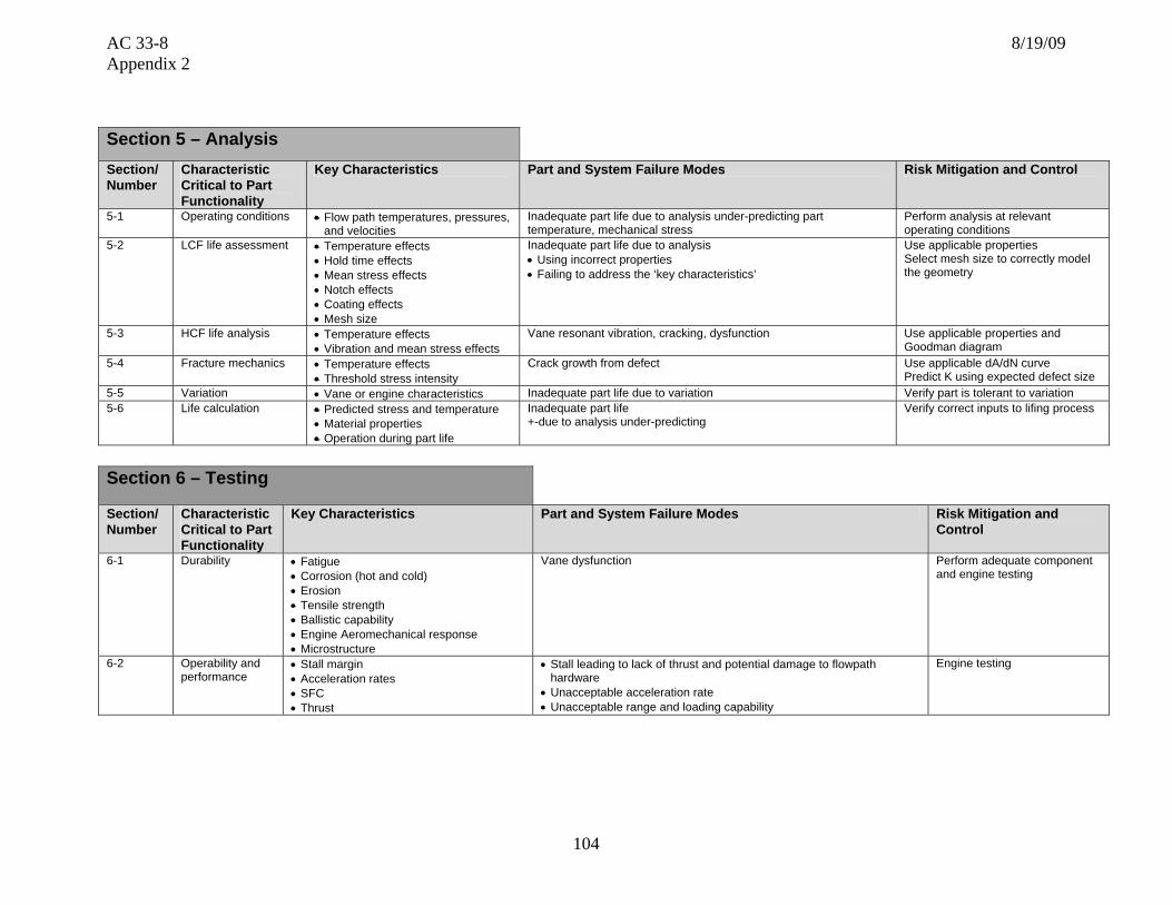
AC 33-8 8/19/09 Appendix 2
104
Section 5 – Analysis Section/ Number
Characteristic Critical to Part Functionality
Key Characteristics Part and System Failure Modes Risk Mitigation and Control
5-1 Operating conditions • Flow path temperatures, pressures, and velocities
Inadequate part life due to analysis under-predicting part temperature, mechanical stress
Perform analysis at relevant operating conditions
5-2 LCF life assessment • Temperature effects • Hold time effects • Mean stress effects • Notch effects • Coating effects • Mesh size
Inadequate part life due to analysis • Using incorrect properties • Failing to address the ‘key characteristics’
Use applicable properties Select mesh size to correctly model the geometry
5-3 HCF life analysis • Temperature effects • Vibration and mean stress effects
Vane resonant vibration, cracking, dysfunction Use applicable properties and Goodman diagram
5-4 Fracture mechanics • Temperature effects • Threshold stress intensity
Crack growth from defect Use applicable dA/dN curve Predict K using expected defect size
5-5 Variation • Vane or engine characteristics Inadequate part life due to variation Verify part is tolerant to variation 5-6 Life calculation • Predicted stress and temperature
• Material properties • Operation during part life
Inadequate part life +-due to analysis under-predicting
Verify correct inputs to lifing process
Section 6 – Testing
Section/ Number
Characteristic Critical to Part Functionality
Key Characteristics Part and System Failure Modes Risk Mitigation and Control
6-1 Durability • Fatigue • Corrosion (hot and cold) • Erosion • Tensile strength • Ballistic capability • Engine Aeromechanical response • Microstructure
Vane dysfunction Perform adequate component and engine testing
6-2 Operability and performance
• Stall margin • Acceleration rates • SFC • Thrust
• Stall leading to lack of thrust and potential damage to flowpath hardware
• Unacceptable acceleration rate • Unacceptable range and loading capability
Engine testing

AC 33-8 8/19/09 Appendix 2
105
Section 7 – Potential Impact on Regulatory Requirements
Note: The regulatory requirements identified below, which are inclusive up to Amendment 20 of 14 CFR part 33, are intended as a guide to applicants when determining the applicable regulations to which they must show compliance. Those requirements listed as “Could be affected” highlight the regulations whose compliance findings are typically affected by the component or part that this template is addressing. This guide is not all-inclusive and the applicant remains responsible for identifying the certification basis of the product on which their PMA part is to be installed.
Applicable 14 CFR Part 33 Regulatory
Requirements Comments
Subpart – A General
1. 33.4 Instructions for Continued Airworthiness Could be affected ICAs including on-wing inspection requirements and on-wing limits
2. 33.5 Instruction manual for installing and operating the engine
3. 33.7 Engine ratings and operating limitations
4. 33.8 Selection of engine power and thrust ratings
Subpart B – Design and Construction;
General
5. 33.14 Start-stop cyclic stress (low cycle fatigue)
6. 33.15 Materials Could be affected
7. 33.17 Fire prevention Could be affected Titanium fire
8. 33.19 Durability Could be affected
9. 33.21 Engine cooling
10. 33.23 Engine mounting attachments and structure
11. 33.25 Accessory attachments
12. 33.27 Turbine, compressor, fan, and turbo-supercharger rotors
13. 33.28 Electrical and electronic control systems
14. 33.29 Instrumentation connection

AC 33-8 8/19/09 Appendix 2
106
Subpart E – Design and Construction;
Turbine Aircraft Engines
15. 33.62 Stress analysis
16. 33.63 Vibration Could be affected Vane vibration-Design
17. 33.65 Surge and stall characteristics Could be affected Compressor stall line - Operating line migration due to erosion
18. 33.66 Bleed air systems Could be affected Pressure at bleed location
19. 33.67 Fuel system
20. 33.68 Induction system icing (Operability aspects) Could be affected Bleed temperature impacts icing system
21. 33.69 Ignition system
22. 33.71 Lubrication system
23. 33.72 Hydraulic actuating system
24. 33.73 Power or thrust response Could be affected Compressor efficiency/performance
25. 33.74 Continued rotation
26. 33.75 Safety analysis Could be affected Compressor blade release-Case containment
27. 33.76 Bird ingestion (Operability aspects of ingestion)
Could be affected Compromised aero – missing airfoil
28. 33.77 Foreign object ingestion (Operability aspects of ingestion)
Could be affected Compromised aero – missing airfoil
29. 33.78 Rain and hail ingestion
30. 33.79 Fuel burning thrust augmenter
Subpart F – Block Tests; Turbine Aircraft
Engines
31. 33.83 Vibration test Could be affected Vane vibration-Demonstration test
32. 33.85 Calibration tests
33. 33.87 Endurance test Could be affected Vane durability
34. 33.88 Engine over temperature test
35. 33.89 Operation test

AC 33-8 8/19/09 Appendix 2
107
Subpart F – Block Tests; Turbine Aircraft Engines
36. 33.90 Initial maintenance inspection Could be affected Vane in-service inspection limits
37. 33.91 Engine component tests
38. 33.92 Rotor locking tests
39. 33.93 Teardown inspection
40. 33.94 Blade containment and rotor unbalance tests (Weight changes)
41. 33.95 Engine-propeller system tests
42. 33.96 Engine tests in auxiliary power unit (APU) mode
43. 33.97 Thrust reversers
44. 33.99 General conduct of block tests
45. Part 33 - Appendix A – Instructions for Continued
Airworthiness Could be affected
46. Part 33 - Appendix B - Certification Standard Atmospheric Concentrations of Rain and Hail

AC 33-8 8/19/09 Appendix 2
108
Template #12: Compressor Blade
Nomenclature for Generic Component Features (all features may not be applicable)
Tip Caps
Squealer Tip
Airfoil
Trailing Edge
Platform
Dovetail Shank
Leading Edge
Shrouds

AC 33-8 8/19/09 Appendix 2
109
Section 1 – Part Functional capability, i.e., the action(s) that the part is designed to perform in the product Section/Number
Characteristic Critical to Part Functionality
Key Characteristics Part and System Failure Modes Risk Mitigation and Control
1-1 Weight • As-forged surfaces • Machined surfaces
Dovetail and disk loading-dysfunction
Surface dimensional process control
1-2 Moment of weight - center of gravity • Axial • Tangential • Radial
• As-forged surfaces • Machined surfaces • Mass/density distribution
Dovetail and disk loading-dysfunction Surface dimensional process control
1-3 Vibration characteristics (HCF capability)
• Blade natural frequencies • Vibration stress distribution • Cycles to failure demonstration • Vibration test set-up and execution criteria, i.e.,
establishing parameters for blade holding, loading, excitation modes determination, and excitation sensing techniques
Blade resonant vibration, cracking, dysfunction • Resonance avoidance at steady state operation with margin
• Vibratory and steady state stress within Goodman Diagram limits
1-4 LCF, fracture toughness, tensile overload capability
• Blade geometry • Material mechanical/metallurgical/physical
properties
• Blade separation from tensile overload • Crack growth from LCF, HCF, or HCF/LCF interaction • Loss of tip fatigue strength from rubbing
Verify capability exceeds expected utilization
1-5 Part span shrouds • Shroud geometry • Shroud location on airfoil • Wear resistance on mating component
• Blade vibration: airfoil cracking • Blade dysfunction during FOD event
• Surface dimensional process control
• Verify acceptable wear couple
1-6 Squealer tip • Squealer tip geometry • Excessive rub load • Tip cracking or corner loss
Surface dimensional process control

AC 33-8 8/19/09 Appendix 2
110
Section 2 – Part Shape, size, dimensions and other physical measurable parameters, and interconnectivity with an engine integral part/systemSection/Number
Characteristic Critical to Part Functionality
Key Characteristics Part and System Failure Modes Risk Mitigation and Control
2-1 Dovetail • Shape • Surface contour • Tang relative location and taper • Tolerance (blade root and disk slot
dimensional spectrums and blade producibility limitations)
• Unbalance tang loading/blade dysfunction • Incorrect loading on disk/cracking
Dimensional process control and inspection
2-2 Platform • Width • Length • Inner gas path contour
• Width: binding, recirculation • Length: rotor/stator rubs • Platform resonant vibration, cracking, dysfunction
Dimensional process control
2-3 Airfoil external shape
• Aero contour/stagger angle • Leading edge contour • Thickness distribution • Chord
• Poor aero performance • Airfoil vibratory mode changes due to thickness distribution • Operability issues – stall leading to lack of thrust and potential
damage to flowpath hardware • FOD tolerance • Supply bleed pressure – insufficient mass flow to turbine blade
and/or rotor cavity leading to turbine blade/rotor dysfunction • Weight - Dovetail and disk loading-dysfunction • Airfoil stress/life
Surface dimensional process control
2-4 Tolerance • Variance-fluctuations in measurements • Measurement gauge repeatability and
reliability
Mechanical/functional, failure due to variation from nominal • Verify part is tolerant to variation
• Control of manufacturing and inspection processes
2-5 Airfoil to platform filets
• Filet profile Failure due to stress concentration • Dimensional process control

AC 33-8 8/19/09 Appendix 2
111
Section 3 – Part Materials and Processes – Properties Section/Number
Characteristic Critical to Part Functionality
Key Characteristics Part and System Failure Modes Risk Mitigation and Control
3-1 Chemistry • Major elements - % variation • Impurities
• Poor mechanical or environmental properties Material selection Process control
3-2 Physical properties • Density • Coefficient of thermal expansion • Melting point
• Excessive blade weight • Interference with surrounding hardware
Verify: • Acceptable blade weight • Acceptable stresses • Blade “fit” in hot condition
3-3 Mechanical /metallurgical properties
• Modulus • Forging grain flow angles • Bare and coated: tensile (UTS, YS,
elongation, stress rupture, creep, LCF, HCF)
• Long term metallurgical stability • Impact properties
• Undesirable natural frequencies • Low material properties, blade dysfunction • Material capability consumed in operation
Verify: • Acceptable stresses and frequencies • Forging grain flow as required • Adequate material properties • Operational effects accounted for • Impact testing
3-4 Forged structure • Grain structure (size, shape, flow, boundaries)
• Directional properties • Hardness • Forging laps • Homogeneity of forging work throughout
part
Material property reduction due to abnormal grain structure, blade dysfunction
Verify that variations in grain structure are accounted for Process control and inspection
3-5 Environmental resistance
• Oxidation, corrosion, erosion, fretting resistance
• Elevated temperature stress relaxation, alpha case formation)
• Rubbing, FOD resistance
• Cracking from oxidation/corrosion pitting, blade dysfunction
• Property reduction due to brittle Alpha case, blade dysfunction
Verify adequate environmental and wear properties
3-6 Environmental coating
• Coverage and thickness • Long term stability • Corrosion resistance
Cracking from corrosion pitting Control of chemistry and application process Verify thermal-mechanical compatibility with base material
3-7 Ti Fire resistance • Rub rate (clearances, relative motion) • Environment (temperature, pressure) • Material of adjacent hardware
3-8 Dovetail anti-fret coating
• Wear resistance and abrasiveness • Coverage and thickness • Temperature capability
• Loss of material leading to dysfunction of blade and/or disk
• Unbalanced loading leading to dysfunction of blade and/or disk
Verify acceptable wear couple Control of chemistry and application process Verify adequate temperature capability
3-9 Erosion coating • Erosion resistance • Compatibility with base material
• Performance and operability degradation • Blade dysfunction due to material property degradation
Verify adequate erosion characteristics and base material compatibility
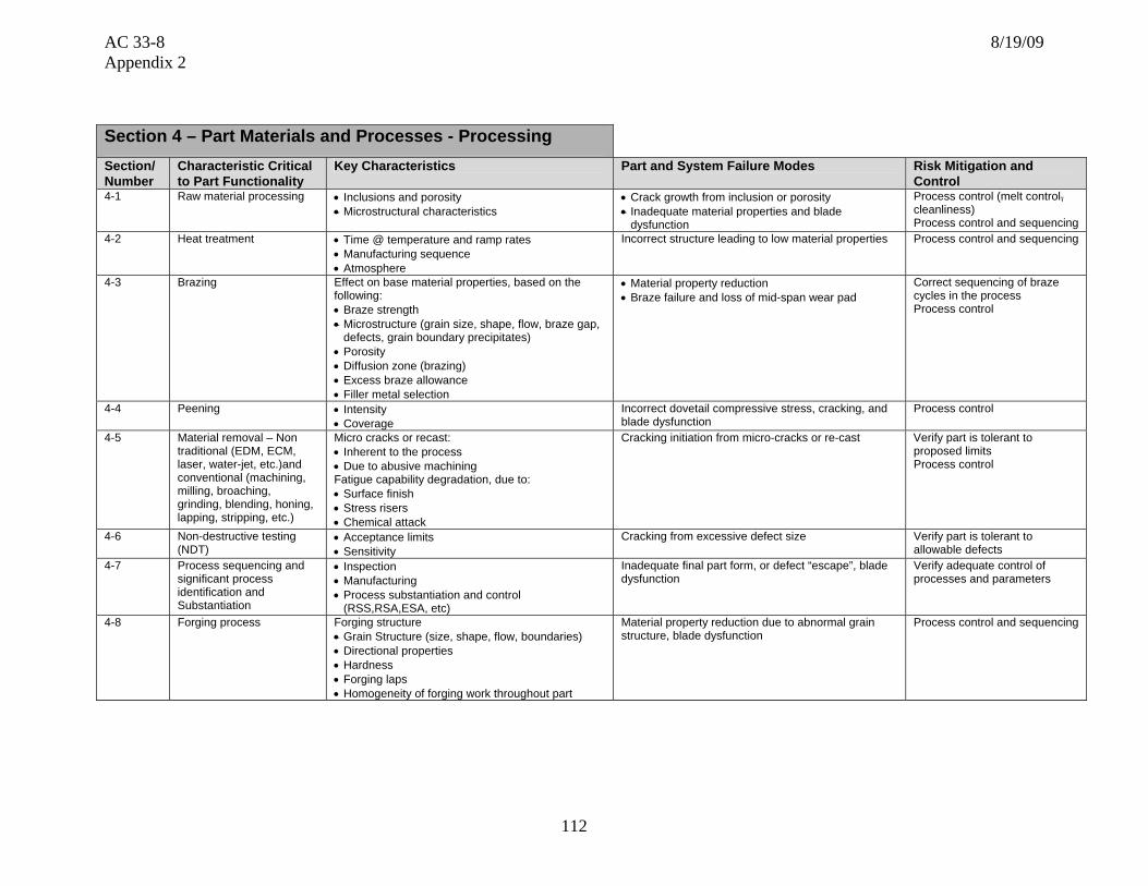
AC 33-8 8/19/09 Appendix 2
112
Section 4 – Part Materials and Processes - Processing Section/ Number
Characteristic Critical to Part Functionality
Key Characteristics Part and System Failure Modes Risk Mitigation and Control
4-1 Raw material processing • Inclusions and porosity • Microstructural characteristics
• Crack growth from inclusion or porosity • Inadequate material properties and blade
dysfunction
Process control (melt control, cleanliness) Process control and sequencing
4-2 Heat treatment • Time @ temperature and ramp rates • Manufacturing sequence • Atmosphere
Incorrect structure leading to low material properties
Process control and sequencing
4-3 Brazing Effect on base material properties, based on the following: • Braze strength • Microstructure (grain size, shape, flow, braze gap,
defects, grain boundary precipitates) • Porosity • Diffusion zone (brazing) • Excess braze allowance • Filler metal selection
• Material property reduction • Braze failure and loss of mid-span wear pad
Correct sequencing of braze cycles in the process Process control
4-4 Peening • Intensity • Coverage
Incorrect dovetail compressive stress, cracking, and blade dysfunction
Process control
4-5 Material removal – Non traditional (EDM, ECM, laser, water-jet, etc.)and conventional (machining, milling, broaching, grinding, blending, honing, lapping, stripping, etc.)
Micro cracks or recast: • Inherent to the process • Due to abusive machining Fatigue capability degradation, due to: • Surface finish • Stress risers • Chemical attack
Cracking initiation from micro-cracks or re-cast Verify part is tolerant to proposed limits Process control
4-6 Non-destructive testing (NDT)
• Acceptance limits • Sensitivity
Cracking from excessive defect size Verify part is tolerant to allowable defects
4-7 Process sequencing and significant process identification and Substantiation
• Inspection • Manufacturing • Process substantiation and control
(RSS,RSA,ESA, etc)
Inadequate final part form, or defect “escape”, blade dysfunction
Verify adequate control of processes and parameters
4-8 Forging process Forging structure • Grain Structure (size, shape, flow, boundaries) • Directional properties • Hardness • Forging laps • Homogeneity of forging work throughout part
Material property reduction due to abnormal grain structure, blade dysfunction
Process control and sequencing

AC 33-8 8/19/09 Appendix 2
113
Section 5 – Analysis Section/ Number
Characteristic Critical to Part Functionality
Key Characteristics Part and System Failure Modes Risk Mitigation and Control
5-1 Operating conditions • Flow path temperatures, pressures, and velocities
• Rotor speed
Inadequate part life due to analysis under-predicting part temperature, mechanical stress
Perform analysis at relevant operating conditions
5-2 LCF life assessment – airfoil and shank
• Temperature effects • Hold time effects • Mean stress effects • Notch effects • Coating effects • Mesh size
Inadequate part life due to analysis • Using incorrect properties • Failing to address the ‘key characteristics’
• Use applicable properties • Select mesh size to correctly model
the geometry
5-3 HCF life analysis • Temperature effects • Vibration and mean stress effects
Blade resonant vibration, cracking, dysfunction Use applicable properties and Goodman diagram
5-4 Creep and rupture life analysis
• Temperature effects • Material thickness effects
Blade rupture cracking, dysfunction Use applicable properties
5-5 Fracture mechanics • Temperature effects • Threshold stress intensity
Crack growth from defect • Use applicable dA/dN curve • Predict K using expected defect
size 5-6 Variation • Blade or engine characteristics Inadequate part life due to variation Verify part is tolerant to variation 5-7 Life calculation • Predicted stress and temperature
• Root loading profile shifts • Material properties • Operation during part life • Life impact on disk
Inadequate part life due to analysis under-predicting Verify correct inputs to lifing process

AC 33-8 8/19/09 Appendix 2
114
Section 6 – Testing
Section/ Number
Characteristic Critical to Part Functionality
Key Characteristics Part and System Failure Modes Risk Mitigation and Control
6-1 Durability • Fatigue • Corrosion (hot and cold) • Erosion • Creep • Tensile strength • Ballistic capability • Engine Aeromechanical response • Microstructure
Blade dysfunction Perform adequate component and/or engine testing
6-2 Operability and Performance
• Stall margin • Acceleration rates • SFC • Thrust
• Stall leading to lack of thrust and potential damage to flowpath hardware
• Unacceptable acceleration rate • Unacceptable range and loading capability
Engine testing
Section 7 – Potential Impact on Regulatory Requirements
Note: The regulatory requirements identified below, which are inclusive up to Amendment 20 of 14 CFR part 33, are intended as a guide to applicants when determining the applicable regulations to which they must show compliance. Those requirements listed as “Could be affected” highlight the regulations whose compliance findings are typically affected by the component or part that this template is addressing. This guide is not all-inclusive and the applicant remains responsible for identifying the certification basis of the product on which their PMA part is to be installed.
Applicable 14 CFR Part 33 Regulatory
Requirements Comments
Subpart A – General
1. 33.4 Instructions for Continued Airworthiness Could be affected ICAs including on-wing inspection requirements and on-wing limits
2. 33.5 Instruction manual for installing and operating the engine
3. 33.7 Engine ratings and operating limitations
4. 33.8 Selection of engine power and thrust ratings

AC 33-8 8/19/09 Appendix 2
115
Subpart B – Design and Construction; General
5. 33.14 Start-stop cyclic stress (low cycle fatigue) Could be affected Weight and center-of-gravity affect on rotor forces and LCF capability
6. 33.15 Materials Could be affected
7. 33.17 Fire prevention Could be affected Titanium fire
8. 33.19 Durability Could be affected
9. 33.21 Engine cooling
10. 33.23 Engine mounting attachments and structure
11. 33.25 Accessory attachments
12. 33.27 Turbine, compressor, fan, and turbo-supercharger rotors
Could be affected Weight affect on rotor forces during over-speed
13. 33.28 Electrical and electronic control systems
14. 33.29 Instrumentation connection
Subpart E – Design and Construction; Turbine Aircraft Engines
15. 33.62 Stress analysis Could be affected Rotor stress analysis
16. 33.63 Vibration Could be affected Blade vibration-Design
17. 33.65 Surge and stall characteristics Could be affected Compressor stall line - Operating line migration due to erosion
18. 33.66 Bleed air systems Could be affected Pressure at bleed location
19. 33.67 Fuel system
20. 33.68 Induction system icing (Operability aspects) Could be affected Bleed temperature impacts icing system
21. 33.69 Ignition system
22. 33.71 Lubrication system
23. 33.72 Hydraulic actuating system
24. 33.73 Power or thrust response Could be affected Compressor efficiency/performance
25. 33.74 Continued rotation
26. 33.75 Safety analysis Could be affected Compressor blade release-Case containment
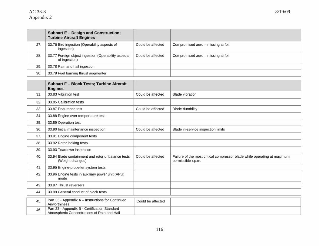
AC 33-8 8/19/09 Appendix 2
116
Subpart E – Design and Construction; Turbine Aircraft Engines
27. 33.76 Bird ingestion (Operability aspects of ingestion)
Could be affected Compromised aero – missing airfoil
28. 33.77 Foreign object ingestion (Operability aspects of ingestion)
Could be affected Compromised aero – missing airfoil
29. 33.78 Rain and hail ingestion
30. 33.79 Fuel burning thrust augmenter
Subpart F – Block Tests; Turbine Aircraft Engines
31. 33.83 Vibration test Could be affected Blade vibration
32. 33.85 Calibration tests
33. 33.87 Endurance test Could be affected Blade durability
34. 33.88 Engine over temperature test
35. 33.89 Operation test
36. 33.90 Initial maintenance inspection Could be affected Blade in-service inspection limits
37. 33.91 Engine component tests
38. 33.92 Rotor locking tests
39. 33.93 Teardown inspection
40. 33.94 Blade containment and rotor unbalance tests (Weight changes)
Could be affected Failure of the most critical compressor blade while operating at maximum permissible r.p.m.
41. 33.95 Engine-propeller system tests
42. 33.96 Engine tests in auxiliary power unit (APU) mode
43. 33.97 Thrust reversers
44. 33.99 General conduct of block tests
45. Part 33 - Appendix A – Instructions for Continued Airworthiness
Could be affected
46. Part 33 - Appendix B - Certification Standard Atmospheric Concentrations of Rain and Hail

AC 33-8 8/19/09 Appendix 2
117
Template #13: Static Air Seal
Honeycomb/Rubber/Teflon on Sheet metal/Machined Forging
Nomenclature for Generic Component Features (all features may not be applicable)

AC 33-8 8/19/09 Appendix 2
118
Section 1 – Part Functional capability, i.e., the action(s) that the part is designed to perform in the product Section/Number
Characteristic Critical to Part Functionality
Key Characteristics Part and System Failure Modes Risk Mitigation and Control
1-1 Tensile capability • Material mechanical/metallurgical/physical properties
• Seal failure. Excessive contact. Rotating part dysfunction Verify capability exceeds expected utilization
1-2 Abradability-solid • Material mechanical/physical properties • Machinabilty by rotating seal teeth • Environmental temperature capability
• Thermal instability. Rotating part dysfunction • Rotating seal tooth cracking. Rotating part dysfunction • Excessive seal wear/leakage
Verify compatibility to rotating seal
1-3 Cutting characteristics-honeycomb
• Material mechanical/metallurgical/physical properties
• Machinabilty by rotating seal teeth • Foil thickness. cell size. braze wicking
• Thermal instability. Rotating part dysfunction • Rotating seal tooth cracking. Rotating part dysfunction • Excessive seal wear/leakage
Verify compatibility to rotating seal
Section 2 – Part Shape, size, dimensions and other physical measurable parameters, and interconnectivity with an engine integral part/system Section/Number
Characteristic Critical to Part Functionality
Key Characteristics Part and System Failure Modes Risk Mitigation and Control
2-1 Tolerance • Variance-fluctuations in measurements • Measurement gauge repeatability and reliability
Mechanical/Functional, failure due to variation from nominal • Verify part is tolerant to variation
• Control of manufacturing and inspection processes
2-2 Retention/hook geometry
• Thickness • Axial length • Radius
Excessive wear, looseness of fit, excessive seal clearance, performance impact
• Dimensional process control and inspection geometry
2-3 Anti-rotation feature • Location • Bearing surface area • Crimping
Arch-binding, mechanical failure due to excessive seal rub, rotating part dysfunction
• Dimensional process control and inspection geometry
2-4 Honeycomb/ abradable geometry
• Inner diameter • Cell depth
Failure to seal, performance impact Excess rub, rotating part dysfunction Fatigue failure
• Dimensional process control and inspection geometry
2-5 Backing plate geometry
• Arc length • Inner diameter
Arch-binding, mechanical failure due to excessive seal rub, rotating part dysfunction
• Dimensional process control and inspection geometry

AC 33-8 8/19/09 Appendix 2
119
Section 3 – Part Materials and Processes – Properties Section/Number
Characteristic Critical to Part Functionality
Key Characteristics Part and System Failure Modes Risk Mitigation and Control
3-1 Chemistry • Major elements - % Variation • Impurities
• Poor mechanical or environmental properties Material selection 3-2 Physical properties • Thermal conductivity
• Coefficient of thermal expansion • Interference with surrounding hardware Verify:
• Acceptable stresses • Seal “fit” in hot condition
3-3 Mechanical properties
• Wrought structure • Hardness/grain size • Modulus • Tensile (UTS, YS) • Long term metallurgical stability
• Low material properties • Material capability consumed in operation • Low material properties, seal dysfunction
Verify: • Acceptable stresses • Adequate material properties • Operational effects accounted for • Relevant properties are used
3-4 Environmental resistance
• Oxidation, corrosion, erosion, fretting resistance
Cracking from oxidation/corrosion pitting, seal dysfunction Verify adequate environmental properties
Section 4 – Part Materials and Processes - Processing Section/ Number
Characteristic Critical to Part Functionality
Key Characteristics Part and System Failure Modes Risk Mitigation and Control
4-1 Heat treatment • Time @ temperature and ramp rates • Manufacturing sequence • Atmosphere
Low material properties Process control and sequencing
4-2 Brazing Effect on base material properties, based on the following: • Braze strength • Microstructure, braze gap, defects, Porosity • Diffusion zone (brazing) • Excess braze allowance • Filler metal selection
Material property reduction, braze failure
• Correct sequencing of braze cycles in the process
• Process control
4-3 Material removal – Non traditional (EDM, ECM, Laser, Water-Jet) and conventional (machining, milling, broaching, grinding, blending, honing, lapping, stripping)
Micro cracks or recast: • Inherent to the process • Due to abusive machining Fatigue capability degradation, due to: • Surface finish • Stress risers • Chemical attack
Cracking initiation from micro-cracks or re-cast • Verify part is tolerant to proposed limits
• Process control
4-4 Non-destructive testing (NDT)
• Acceptance limits • Sensitivity
Cracking from excessive defect size Verify part is tolerant to allowable defects
4-5 Process sequencing and significant process identification and substantiation
• Inspection • Manufacturing • Process substantiation and control
(RSS,RSA,ESA, etc)
Inadequate final part form, or defect “escape”, seal dysfunction
Verify adequate control of processes and parameters

AC 33-8 8/19/09 Appendix 2
120
Section 5 – Analysis Section/ Number
Characteristic Critical to Part Functionality
Key Characteristics Part and System Failure Modes Risk Mitigation and Control
5-1 Operating conditions • Cavity temperatures, pressures,
Inadequate part life due to analysis under-predicting part temperature, thermal or mechanical stress
Perform analysis at relevant operating conditions
5-2 Variation • Dimensional characteristics Inadequate part life Verify part is tolerant variation 5-3 Life calculation • Calculated stress and Temperature
• Material properties • Operating during part life
Inadequate part life due to analysis under-predicting Verify correct inputs to life calculation
Section 6 – Testing
Section/ Number
Characteristic Critical to Part Functionality
Key Characteristics Part and System Failure Modes Risk Mitigation and Control
6-1 Durability
• Fatigue • Tensile strength • Cleaning requirements
6-2 Bond Strength

AC 33-8 8/19/09 Appendix 2
121
Section 7 – Potential Impact on Regulatory Requirements
Note: The regulatory requirements identified below, which are inclusive up to Amendment 20 of 14 CFR part 33, are intended as a guide to applicants when determining the applicable regulations to which they must show compliance. Those requirements listed as “Could be affected” highlight the regulations whose compliance findings are typically affected by the component or part that this template is addressing. This guide is not all-inclusive and the applicant remains responsible for identifying the certification basis of the product on which their PMA part is to be installed.
Applicable 14 CFR Part 33 Regulatory
Requirements Comments
Subpart A – General
1. 33.4 Instructions for Continued Airworthiness Could be affected
2. 33.5 Instruction manual for installing and operating the engine
3. 33.7 Engine ratings and operating limitations
4. 33.8 Selection of engine power and thrust ratings
Subpart B – Design and Construction;
General
5. 33.14 Start-stop cyclic stress (low cycle fatigue)
6. 33.15 Materials
7. 33.17 Fire prevention Could be affected
8. 33.19 Durability Could be affected
9. 33.21 Engine cooling Could be affected
10. 33.23 Engine mounting attachments and structure
11. 33.25 Accessory attachments
12. 33.27 Turbine, compressor, fan, and turbo-supercharger rotors
13. 33.28 Electrical and electronic control systems
14. 33.29 Instrumentation connection

AC 33-8 8/19/09 Appendix 2
122
Subpart E – Design and Construction; Turbine Aircraft Engines
15. 33.62 Stress analysis
16. 33.63 Vibration Could be affected
17. 33.65 Surge and stall characteristics Could be affected
18. 33.66 Bleed air systems
19. 33.67 Fuel system
20. 33.68 Induction system icing (Operability aspects)
21. 33.69 Ignition system
22. 33.71 Lubrication system
23. 33.72 Hydraulic actuating system
24. 33.73 Power or thrust response
25. 33.74 Continued rotation
26. 33.75 Safety analysis
27. 33.76 Bird ingestion (Operability aspects of ingestion)
28. 33.77 Foreign object ingestion (Operability aspects of ingestion)
29. 33.78 Rain and hail ingestion
30. 33.79 Fuel burning thrust augmenter
Subpart F – Block Tests; Turbine Aircraft Engines
31. 33.83 Vibration test
32. 33.85 Calibration tests
33. 33.87 Endurance test Could be affected Durability
34. 33.88 Engine over temperature test
35. 33.89 Operation test
36. 33.90 Initial maintenance inspection

AC 33-8 8/19/09 Appendix 2
123
Subpart F – Block Tests; Turbine Aircraft Engines
37. 33.91 Engine component tests
38. 33.92 Rotor locking tests
39. 33.93 Teardown inspection
40. 33.94 Blade containment and rotor unbalance tests (Weight changes)
41. 33.95 Engine-propeller system tests
42. 33.96 Engine tests in auxiliary power unit (APU) mode
43. 33.97 Thrust reversers
44. 33.99 General conduct of block tests
45. Part 33 - Appendix A – Instructions for Continued Airworthiness
Could be affected
46. Part 33 - Appendix B - Certification Standard Atmospheric Concentrations of Rain and Hail
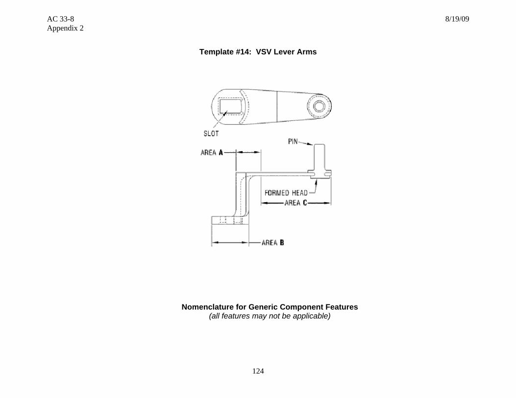
AC 33-8 8/19/09 Appendix 2
124
Template #14: VSV Lever Arms
Nomenclature for Generic Component Features (all features may not be applicable)

AC 33-8 8/19/09 Appendix 2
125
Section 1 – Part Functional capability, i.e., the action(s) that the part is designed to perform in the product Section/Number
Characteristic Critical to Part Functionality
Key Characteristics Part and System Failure Modes Risk Mitigation and Control
1-1
LCF, HCF, tensile capability
• Material mechanical/metallurgical/physical properties
• Dysfunction of actuation system leading to stall, component failure
Verify capability
1-2
Galvanic corrosion • Compatibility of lever arm and pin material • Dysfunction of actuation system leading to stall, component failure
Verify compatibility in operating environment
1-3 Radial preload • Relative radial position of interface surfaces • Dysfunction of actuation system due to lever arm fatigue or excessive wear
Verify dimensional characteristics
Section 2 – Part Shape, size, dimensions and other physical measurable parameters, and interconnectivity with an engine integral part/system Section/Number
Characteristic Critical to Part Functionality
Key Characteristics Part and System Failure Modes Risk Mitigation and Control
2-1 Slot • Width • Thickness • Corner radii
Incorrect fit leading into fretting at vane interface Excessive wear lead into vane actuation failure Fatigue failure
• Dimensional process control and inspection
2-2 Pin • Location relative to slot • Diameter
Incorrect VSV travel leading to stall
• Dimensional process control and inspection
2-3 Spherical bearing • Location relative to slot • Allowable misalignment
Incorrect VSV travel leading to stall • Dimensional process control and inspection
2-4 Web geometry • Cross sectional properties Dysfunction of lever arm through tensile, LCF or HCF Interference with case feature leading to limited travel
• Dimensional process control and inspection

AC 33-8 8/19/09 Appendix 2
126
Section 3 – Part Materials and Processes – Properties Section/Number
Characteristic Critical to Part Functionality
Key Characteristics Part and System Failure Modes Risk Mitigation and Control
3-1 Chemistry • Major elements - % variation • Impurities
• Poor mechanical or environmental properties
Material selection and process control
3-2 Physical properties • Coefficient of thermal expansion • Excessive stresses • Interference with surrounding hardware
Verify: • Acceptable stresses • Lever arm “fit” in hot condition
3-3 Mechanical /metallurgical properties
• Modulus • Wrought structure • Hardness/grain size • Compressive/tensile (UTS, YS) • LCF, HCF • Long term metallurgical stability
• Excessive strain-controlled stress • Undesirable natural frequency • Low material properties
Verify: • Acceptable stresses • Adequate material properties • Operational effects accounted for • Relevant properties are used
3-4 Environmental resistance
• Corrosion Cracking at pin/arm interface due to galvanic attack Verify acceptable galvanic couples
Section 4 – Part Materials and Processes - Processing Section/ Number
Characteristic Critical to Part Functionality
Key Characteristics Part and System Failure Modes Risk Mitigation and Control
4-1 Heat treatment • Time @ temperature and ramp rates • Manufacturing sequence
Incorrect morphology leading to low material properties
Process control and sequencing
4-2 Shot peen • Intensity • Coverage
Fatigue capability degradation lead to potential lever arm dysfunction
Process control
4-3 Material removal - Non traditional - Conventional machining
Micro cracks or recast: • Inherent to the process • Due to abusive machining Fatigue capability degradation, due to: • Surface finish • Stress risers • Chemical attack
Cracking initiation from micro-cracks or re-cast
• Verify part is tolerant to proposed limits
• Process control
4-4 Non-destructive testing (NDT)
• Acceptance limits • Sensitivity
Cracking from excessive defect size Verify part is tolerant to allowable defects
4-5 Process sequencing including coating Significant process identification and substantiation
• Inspection • Manufacturing • Process substantiation
Inadequate final part form, or defect “escape”, bushing dysfunction
Verify adequate control of processes and parameters
4-6 Pin riveting • Head and hole geometry • Assembled condition
Inadequate assembly lead to wear/fatigue cracking and riveted joint dysfunction
Verify adequate control of processes and parameters
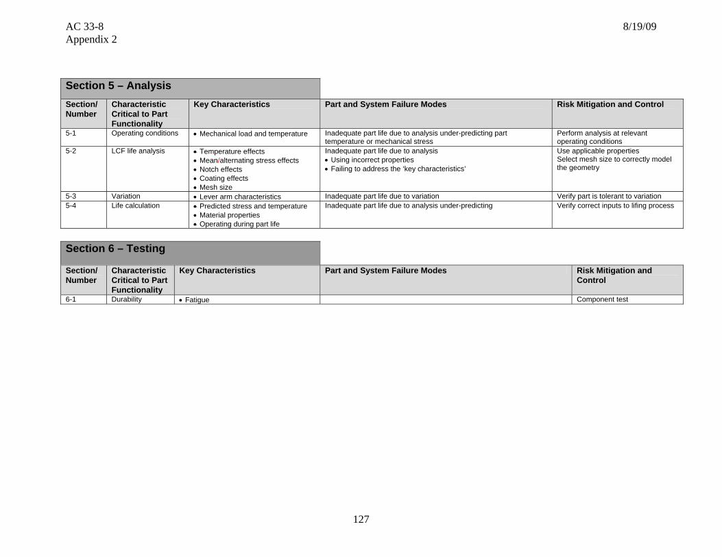
AC 33-8 8/19/09 Appendix 2
127
Section 5 – Analysis Section/ Number
Characteristic Critical to Part Functionality
Key Characteristics Part and System Failure Modes Risk Mitigation and Control
5-1 Operating conditions • Mechanical load and temperature
Inadequate part life due to analysis under-predicting part temperature or mechanical stress
Perform analysis at relevant operating conditions
5-2 LCF life analysis • Temperature effects • Mean/alternating stress effects • Notch effects • Coating effects • Mesh size
Inadequate part life due to analysis • Using incorrect properties • Failing to address the ‘key characteristics’
Use applicable properties Select mesh size to correctly model the geometry
5-3 Variation • Lever arm characteristics Inadequate part life due to variation Verify part is tolerant to variation 5-4 Life calculation
• Predicted stress and temperature • Material properties • Operating during part life
Inadequate part life due to analysis under-predicting
Verify correct inputs to lifing process
Section 6 – Testing
Section/ Number
Characteristic Critical to Part Functionality
Key Characteristics Part and System Failure Modes Risk Mitigation and Control
6-1 Durability • Fatigue Component test

AC 33-8 8/19/09 Appendix 2
128
Section 7 – Potential Impact on Regulatory Requirements
Note: The regulatory requirements identified below, which are inclusive up to Amendment 20 of 14 CFR part 33, are intended as a guide to applicants when determining the applicable regulations to which they must show compliance. Those requirements listed as “Could be affected” highlight the regulations whose compliance findings are typically affected by the component or part that this template is addressing. This guide is not all-inclusive and the applicant remains responsible for identifying the certification basis of the product on which their PMA part is to be installed.
Applicable 14 CFR Part 33 Regulatory
Requirements Comments
Subpart A – General
1. 33.4 Instructions for Continued Airworthiness Could be affected
2. 33.5 Instruction manual for installing and operating the engine
3. 33.7 Engine ratings and operating limitations
4. 33.8 Selection of engine power and thrust ratings
Subpart B – Design and Construction;
General
5. 33.14 Start-stop cyclic stress (low cycle fatigue)
6. 33.15 Materials Could be affected
7. 33.17 Fire prevention
8. 33.19 Durability Could be affected
9. 33.21 Engine cooling
10. 33.23 Engine mounting attachments and structure
11. 33.25 Accessory attachments
12. 33.27 Turbine, compressor, fan, and turbo-supercharger rotors
13. 33.28 Electrical and electronic control systems
14. 33.29 Instrumentation connection

AC 33-8 8/19/09 Appendix 2
129
Subpart E – Design and Construction; Turbine Aircraft Engines
15. 33.62 Stress analysis
16. 33.63 Vibration
17. 33.65 Surge and stall characteristics Could be affected If vane location and angular tolerance is different, compressor stall margin may be affected.
18. 33.66 Bleed air systems
19. 33.67 Fuel system
20. 33.68 Induction system icing (Operability aspects)
21. 33.69 Ignition system
22. 33.71 Lubrication system
23. 33.72 Hydraulic actuating system
24. 33.73 Power or thrust response
25. 33.74 Continued rotation
26. 33.75 Safety analysis
27. 33.76 Bird ingestion (Operability aspects of ingestion)
28. 33.77 Foreign object ingestion (Operability aspects of ingestion)
29. 33.78 Rain and hail ingestion
30. 33.79 Fuel burning thrust augmenter
Subpart F – Block Tests; Turbine Aircraft
Engines
31. 33.83 Vibration test Could be affected If vane location and angular tolerance is different, blade/vane resonance could be affected.
32. 33.85 Calibration tests
33. 33.87 Endurance test Could be affected Lever arm
34. 33.88 Engine over temperature test

AC 33-8 8/19/09 Appendix 2
130
Subpart F – Block Tests; Turbine Aircraft Engines
35. 33.89 Operation test Could be affected
36. 33.90 Initial maintenance inspection
37. 33.91 Engine component tests
38. 33.92 Rotor locking tests
39. 33.93 Teardown inspection Could be affected Visual Inspection
40. 33.94 Blade containment and rotor unbalance tests (Weight changes)
41. 33.95 Engine-propeller system tests
42. 33.96 Engine tests in auxiliary power unit (APU) mode
43. 33.97 Thrust reversers
44. 33.99 General conduct of block tests
45. Part 33 - Appendix A – Instructions for Continued
Airworthiness Could be affected
46. Part 33 - Appendix B - Certification Standard Atmospheric Concentrations of Rain and Hail

AC 33-8 8/19/09 Appendix 2
131
Template #15: Bushings
Ceramic bushing/ Polymeric bushing/ Metallic bushing
Nomenclature for Generic Component Features
(all features may not be applicable)

AC 33-8 8/19/09 Appendix 2
132
Section 2 – Part Shape, size, dimensions and other physical measurable parameters, and interconnectivity with an engine integral part/system Section/Number
Characteristic Critical to Part Functionality
Key Characteristics Part and System Failure Modes Risk Mitigation and Control
2-1 Diameters • OD, ID, Concentricity • Loose fit leading to mating part vibration failure, or rotor and stator contact
• Unacceptable thin bushing due to eccentricity
• Dimensional process control and inspection
2-2 Tolerance • Variance-fluctuations in measurements • Measurement gauge repeatability and reliability
Improper fit leading to premature failure or binding • Dimensional process control and inspection
2-3 Flange • Thickness • Flatness
Interference at assembly preventing freedom of movement • Dimensional process control and inspection
Section 1 – Part Functional capability, i.e., the action(s) that the part is designed to perform in the product Section/Number
Characteristic Critical to Part Functionality
Key Characteristics Part and System Failure Modes Risk Mitigation and Control
1-1 Fracture toughness • Material mechanical/metallurgical/physical properties
• Dysfunction of bushing due to cracking from shock load, Verify capability
1-2 Wear characteristics • Wear couple • Contact area
• Severe wear leading to gas leakage • Loose fit leading to mating part vibration failure, or rotor
and stator contact
Verify compatibility in operating environment
1-3 Freedom of rotation • Coefficient of friction • Hot dimensional fit
• Coefficient of thermal expansion • Cold fit
• Surface finish
• System seizure-stall, failure of component actuation system • Increase wear rate due to excessive drag
Verify part material and geometry

AC 33-8 8/19/09 Appendix 2
133
Section 3 – Part Materials and Processes – Properties Section/Number
Characteristic Critical to Part Functionality
Key Characteristics Part and System Failure Modes Risk Mitigation and Control
3-1 Chemistry • Major elements - % variation • Impurities
• Poor mechanical or environmental properties • Poor oxidation stability
Material selection and Process control
3-2 Physical properties • Coefficient of thermal expansion
• Excessive thermal stresses • Interference with surrounding hardware
Verify: • Acceptable stresses • Bushing “fit” in hot condition
3-3 Mechanical /metallurgical properties
• Modulus • Compressive tensile (UTS, YS) • Long term metallurgical stability • Max temperature capability
• Excessive strain-controlled stress • Low material properties • Material capability consumed in operation
Verify: • Acceptable stresses • Adequate material properties • Operational effects accounted for • Relevant properties are used
3-4 Environmental resistance
• Oxidation, fretting resistance • Rubbing • Resistance to solvents
Cracking/wear out Verify adequate environmental properties
3-5 Friction modifier coating
• Coverage and thickness • Long term stability • Oxidation resistance
• Increased friction load • Control of chemistry and application process
• Verify stability (thermal and chemical)
Section 4 – Part Materials and Processes – Processing
Section/ Number
Characteristic Critical to Part Functionality
Key Characteristics Part and System Failure Modes Risk Mitigation and Control
4-1 Injection molding cleanliness
• Inclusions and porosity
Crack growth wear from inclusion or porosity
Process control (mold setup, process, and filtration) Process control and sequencing
4-2 Heat treatment • Time @ temperature and ramp rates • Manufacturing sequence • Atmosphere
Incorrect morphology leading to low material properties
Process control and sequencing
4-3 Conventional machining • Surface finish
Excessive wear due to rough surface finish Verify part is tolerant to proposed limits Process control
4-4 Non-destructive testing (NDT)
• Acceptance limits • Sensitivity
Cracking from excessive defect size Verify part is tolerant to allowable defects
4-5 Process sequencing including coating Significant process identification and substantiation
• Inspection • Manufacturing • Process substantiation
Inadequate final part form, or defect “escape”, bushing dysfunction
Verify adequate control of processes and parameters

AC 33-8 8/19/09 Appendix 2
134
Section 5 – Analysis Section/ Number
Characteristic Critical to Part Functionality
Key Characteristics Part and System Failure Modes Risk Mitigation and Control
5-1 Operating conditions • Mechanical load and temperature Inadequate part life due to analysis under-predicting part temperature or mechanical stress
Perform analysis at relevant operating conditions
5-2 Variation • Bushing characteristics Inadequate part life due to variation Verify part is tolerant to variation
5-3 Crush stress calculation
• Predicted stress and temperature • Material properties
Inadequate part life due to excessive wear Verify correct inputs to calculation
Section 6 – Testing
Section/ Number
Characteristic Critical to Part Functionality
Key Characteristics Part and System Failure Modes Risk Mitigation and Control
6-1 Durability • Tensile strength • Wear Rate • Oxidation
Component test
Section 7 – Potential Impact on Regulatory Requirements
Note: The regulatory requirements identified below, which are inclusive up to Amendment 20 of 14 CFR part 33, are intended as a guide to applicants when determining the applicable regulations to which they must show compliance. Those requirements listed as “Could be affected” highlight the regulations whose compliance findings are typically affected by the component or part that this template is addressing. This guide is not all-inclusive and the applicant remains responsible for identifying the certification basis of the product on which their PMA part is to be installed.
Applicable 14 CFR Part 33 Regulatory
Requirements Comments
Subpart A – General
1. 33.4 Instructions for Continued Airworthiness Could be affected
2. 33.5 Instruction manual for installing and operating the engine
3. 33.7 Engine ratings and operating limitations
4. 33.8 Selection of engine power and thrust ratings

AC 33-8 8/19/09 Appendix 2
135
Subpart B – Design and Construction;
General
5. 33.14 Start-stop cyclic stress (low cycle fatigue)
6. 33.15 Materials Could be affected
7. 33.17 Fire prevention
8. 33.19 Durability Could be affected
9. 33.21 Engine cooling
10. 33.23 Engine mounting attachments and structure
11. 33.25 Accessory attachments
12. 33.27 Turbine, compressor, fan, and turbo-supercharger rotors
13. 33.28 Electrical and electronic control systems
14. 33.29 Instrumentation connection
Subpart E – Design and Construction; Turbine Aircraft Engines
15. 33.62 Stress analysis
16. 33.63 Vibration
17. 33.65 Surge and stall characteristics
18. 33.66 Bleed air systems
19. 33.67 Fuel system
20. 33.68 Induction system icing (Operability aspects)
21. 33.69 Ignition system
22. 33.71 Lubrication system
23. 33.72 Hydraulic actuating system
24. 33.73 Power or thrust response
25. 33.74 Continued rotation
26. 33.75 Safety analysis

AC 33-8 8/19/09 Appendix 2
136
Subpart E – Design and Construction; Turbine Aircraft Engines
27. 33.76 Bird Ingestion (Operability aspects of ingestion)
28. 33.77 Foreign object ingestion (Operability aspects of ingestion)
29. 33.78 Rain and hail ingestion
30. 33.79 Fuel burning thrust augmenter
Subpart F – Block Tests; Turbine Aircraft Engines
31. 33.83 Vibration test
32. 33.85 Calibration tests
33. 33.87 Endurance test Could be affected Bushing
34. 33.88 Engine over temperature test
35. 33.89 Operation test
36. 33.90 Initial maintenance inspection
37. 33.91 Engine component tests
38. 33.92 Rotor locking tests
39. 33.93 Teardown inspection
40. 33.94 Blade containment and rotor unbalance tests (Weight changes)
41. 33.95 Engine-propeller system tests
42. 33.96 Engine tests in auxiliary power unit (APU) mode
43. 33.97 Thrust reversers
44. 33.99 General conduct of block tests
45. Part 33 - Appendix A – Instructions for Continued Airworthiness
Could be affected
46. Part 33 - Appendix B - Certification Standard Atmospheric Concentrations of Rain and Hail

AC 33-8 8/19/09 Appendix 2
137
Template #16: Turbine Blade Cooled
Nomenclature for Generic Component Features (all features may not be applicable)
Tip Dust/Cooling Holes
Tip Caps Squealer Tip
Airfoil
Pressure Side Bleed (PSB) Slots
Trailing Edge (TE)
Pressure Face Film Cooling Holes
Platform
Dovetail Shank
Damper/Seal Retention Lugs
Angel Wing
LE Radial Film Holes
Leading Edge (LE)
Axial Gill Holes
Platform Rail (Skirt)

AC 33-8 8/19/09 Appendix 2
138
Section 1 – Part Functional capability, i.e., the action(s) that the part is designed to perform in the product Section/Number
Characteristic Critical to Part Functionality
Key Characteristics Part and System Failure Modes Risk Mitigation and Control
1-1 Weight • As-cast surfaces • Machined surfaces
Dovetail and disk loading-dysfunction
Surface dimensional process control
1-2 Moment of weight - center of gravity • Axial • Tangential • Radial
• As-cast surfaces • Machined surfaces • Mass/density distribution
Dovetail and disk loading-dysfunction Surface dimensional process control
1-3 Cooling air utilization • Total flow rate • Individual circuit-cavity flow rate • Flow distribution • Static pressure distribution • Discharge pressure at showerhead, relative to
turbine gas flow pressure
• Low flow: blade over-temperature/dysfunction • High flow: reduced rotor cavity purge/ingestion/part
dysfunction • Poor distribution of cooling air: over-temperature, and
existing bench flow limits not valid
1-4 Vibration damping • Damper fit to blade • Damping ratio
Blade vibration: blade or disk dovetail cracking Control damper seating with blade and/or disk
1-5 Vibration characteristics (HCF capability)
• Blade natural frequencies • Vibration stress distribution • Cycles to failure demonstration • Vibration test set-up and execution criteria, i.e.,
establishing parameters for blade holding, loading, excitation modes determination, and excitation sensing techniques
Blade resonant vibration, cracking, dysfunction Resonance avoidance at steady state operation with margin Vibratory and steady state stress within Goodman diagram limits
1-6 Creep, LCF, fracture toughness, tensile overload capability
• Blade geometry • Blade cooling • Material mechanical/metallurgical/physical
properties • Blade cleaning requirements/effectiveness
(internal passages-intergranual attack)
• Blade separation from tensile overload • Crack growth from LCF or creep – rupture • Loss of tip fatigue strength from rubbing
Verify capability exceeds expected utilization
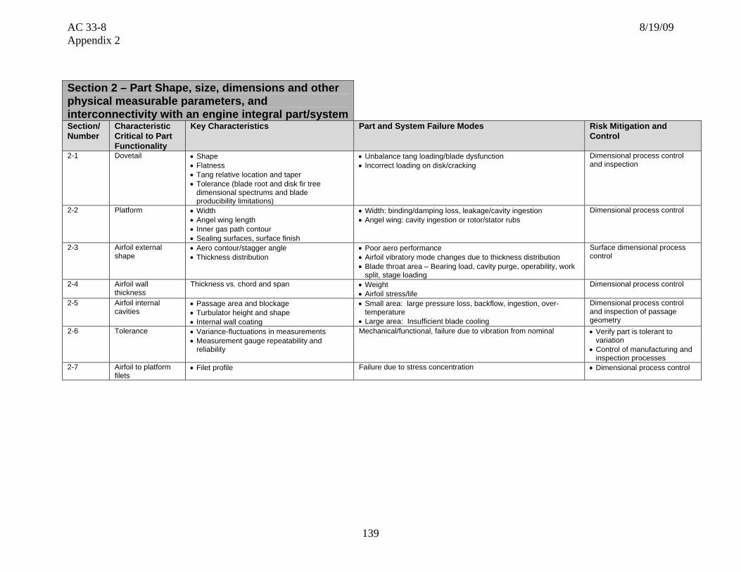
AC 33-8 8/19/09 Appendix 2
139
Section 2 – Part Shape, size, dimensions and other physical measurable parameters, and interconnectivity with an engine integral part/systemSection/Number
Characteristic Critical to Part Functionality
Key Characteristics Part and System Failure Modes Risk Mitigation and Control
2-1 Dovetail • Shape • Flatness • Tang relative location and taper • Tolerance (blade root and disk fir tree
dimensional spectrums and blade producibility limitations)
• Unbalance tang loading/blade dysfunction • Incorrect loading on disk/cracking
Dimensional process control and inspection
2-2 Platform • Width • Angel wing length • Inner gas path contour • Sealing surfaces, surface finish
• Width: binding/damping loss, leakage/cavity ingestion • Angel wing: cavity ingestion or rotor/stator rubs
Dimensional process control
2-3 Airfoil external shape
• Aero contour/stagger angle • Thickness distribution
• Poor aero performance • Airfoil vibratory mode changes due to thickness distribution • Blade throat area – Bearing load, cavity purge, operability, work
split, stage loading
Surface dimensional process control
2-4 Airfoil wall thickness
Thickness vs. chord and span • Weight • Airfoil stress/life
Dimensional process control
2-5 Airfoil internal cavities
• Passage area and blockage • Turbulator height and shape • Internal wall coating
• Small area: large pressure loss, backflow, ingestion, over-temperature
• Large area: Insufficient blade cooling
Dimensional process control and inspection of passage geometry
2-6 Tolerance • Variance-fluctuations in measurements • Measurement gauge repeatability and
reliability
Mechanical/functional, failure due to vibration from nominal • Verify part is tolerant to variation
• Control of manufacturing and inspection processes
2-7 Airfoil to platform filets
• Filet profile Failure due to stress concentration • Dimensional process control

AC 33-8 8/19/09 Appendix 2
140
Section 3 – Part Materials and Processes – Properties Section/Number
Characteristic Critical to Part Functionality
Key Characteristics Part and System Failure Modes Risk Mitigation and Control
3-1 Chemistry • Major elements - % variation • Impurities
• Poor mechanical or environmental properties • Poor TBC adherence
Material selection Master heat and process control
3-2 Physical properties • Density • Thermal conductivity • Coefficient of thermal expansion • Refractive Index (x-rays) • Melting point
• Excessive blade weight • Excessive thermal stresses • Interference with surrounding hardware
Verify: • acceptable blade weight • acceptable stresses • blade “fit” in hot condition
3-3 Mechanical /metallurgical properties
• Modulus (vs. grain orientation) • Columnar crystal orientation angles • Bare and coated: tensile (UTS, YS,
elongation, stress rupture, creep, LCF, HCF)
• Long term metallurgical stability • Thin wall effects
• Excessive strain-controlled stress • Undesirable natural frequency • Low material properties, blade dysfunction • Material capability consumed in operation • Low material properties, blade dysfunction
Verify: • Acceptable stresses and frequencies • Grain orientation, as required • Adequate material properties • Operational effects accounted for • Relevant properties are used
3-4 Cast structure • Grain structure (size, shape, flow, boundaries, gamma prime size and volume fraction, recrystallization)
• High angle boundaries • Inclusions • Freckling • Porosity • Directional properties • Hardness • Melting point • Crack propagation rate • Refractive index
Material property reduction due to excessive grain angle or high angle boundaries (HAB), blade dysfunction
Verify that grain orientation or high angle boundaries are accounted for Process control and inspection
3-5 Environmental resistance
• Oxidation, corrosion, erosion, fretting resistance
• Elevated temperature (creep, diffusion, ageing, temp. gradients)
• Rubbing, FOD resistance
Cracking from oxidation/corrosion pitting, blade dysfunction Verify adequate environmental properties
3-6 Environmental coating
• Coverage and thickness • Long term stability • Oxidation and corrosion resistance
• LCF property reduction due to poor coating selection/requirements, blade cracking
• Cracking from oxidation/corrosion pitting
Control of chemistry and application process Verify thermal-mechanical compatibility with base material

AC 33-8 8/19/09 Appendix 2
141
Section 3 – Part Materials and Processes – Properties Section/Number
Characteristic Critical to Part Functionality
Key Characteristics Part and System Failure Modes Risk Mitigation and Control
3-7 Thermal barrier coating
• Coating material composition and density • Thermal conductivity (coefficient of thermal
expansion) • Coverage and thickness uniformity • Coating and diffusion zone microstructure • Adhesion • Oxidation • Resistance to spalling, sindering, and
erosion • Hardness • Residual stress • Stripping requirements • Bonding (interface contamination) • Compatibility with base material/other
coatings
High thermal stresses or part temperature, blade dysfunction
Control of chemistry and application process Verify part is tolerant to missing TBC No high TBC temperatures that accelerate spalling, or molten dirt infiltration
Section 4 – Part Materials and Processes - Processing Section/ Number
Characteristic Critical to Part Functionality
Key Characteristics Part and System Failure Modes Risk Mitigation and Control
4-1 Casting cleanliness • Inclusions and porosity • Internal surface cleanliness
Crack growth from inclusion or porosity Poor coating adhesion, corrosion and oxidation
Process control (mold setup, casting process, and filtration) Process control and sequencing
4-2 Heat treatment • Time @ temperature and ramp rates • Manufacturing sequence • Atmosphere
Incorrect Gamma prime size/spacing leading to low material properties
Process control and sequencing
4-3 Welding and brazing Effect on base material properties, based on the following: • Weld or braze strength • Microstructure (grain size, shape, flow, braze
gap, defects, grain boundary precipitates, gamma prime and volume fraction)
• Porosity • Diffusion zone (brazing) • Heat affected zone (welding) • Penetration (welding) • Excess braze allowance • Filler metal selection
Material property reduction Braze failure in ‘ball chute’ or at tip, leading to loss of coolant
Correct sequencing of braze or weld cycles in the process Process control

AC 33-8 8/19/09 Appendix 2
142
Section 4 – Part Materials and Processes - Processing Section/ Number
Characteristic Critical to Part Functionality
Key Characteristics Part and System Failure Modes Risk Mitigation and Control
4-4 Shot peen • Intensity • Coverage
Incorrect dovetail compressive stress, cracking, and blade dysfunction
Process control
4-5 Material removal – Non traditional (EDM, ECM, laser, water-jet, etc.) and conventional (machining, milling, broaching, grinding, blending, honing, lapping, stripping, etc.)
Micro cracks or recast: • Inherent to the process • Due to abusive machining Fatigue capability degradation, due to: • Surface finish • Stress risers • Chemical attack
Cracking initiation from micro-cracks or re-cast Verify part is tolerant to proposed limits Process control
4-6 Non-destructive testing (NDT)
• Acceptance limits • Sensitivity
Cracking from excessive defect size Verify part is tolerant to allowable defects
4-7 Process sequencing and significant process identification and substantiation
• Inspection • Manufacturing • Process substantiation and control
(RSS,RSA,ESA, etc)
Inadequate final part form, or defect “escape”, blade dysfunction
Verify adequate control of processes and parameters
Section 5 – Analysis Section/ Number
Characteristic Critical to Part Functionality
Key Characteristics Part and System Failure Modes Risk Mitigation and Control
5-1 Operating conditions • Flow path temperatures, pressures, and velocities
• Rotor speed
Inadequate part life due to analysis under-predicting part temperature, thermal or mechanical stress
Perform analysis at relevant operating conditions
5-2 Blade cooling • Secondary flow circuit • Blade cooling flow • blade cooling
Inadequate part life due to analysis over-predicting the blade cooling
5-3 LCF life analysis – airfoil and shank
• Temperature effects • Multi-axial effects • Hold time effects • Mean stress effects • Notch effects • Coating effects • Mesh size
Inadequate part life due to analysis • Using incorrect properties • Failing to address the ‘key characteristics’
Use applicable properties Select mesh size to correctly model the geometry
5-4 HCF life analysis • Temperature effects • Vibration and mean stress effects
Blade resonant vibration, cracking, dysfunction Use applicable properties and Goodman diagram
5-5 Creep and rupture life analysis
• Temperature effects • Material thickness effects
Blade rupture cracking, dysfunction Use applicable properties
5-6 Fracture mechanics • Temperature effects • Threshold stress intensity • Crack growth rate
Crack growth from defect Use applicable dA/dN curve Predict K using expected defect size
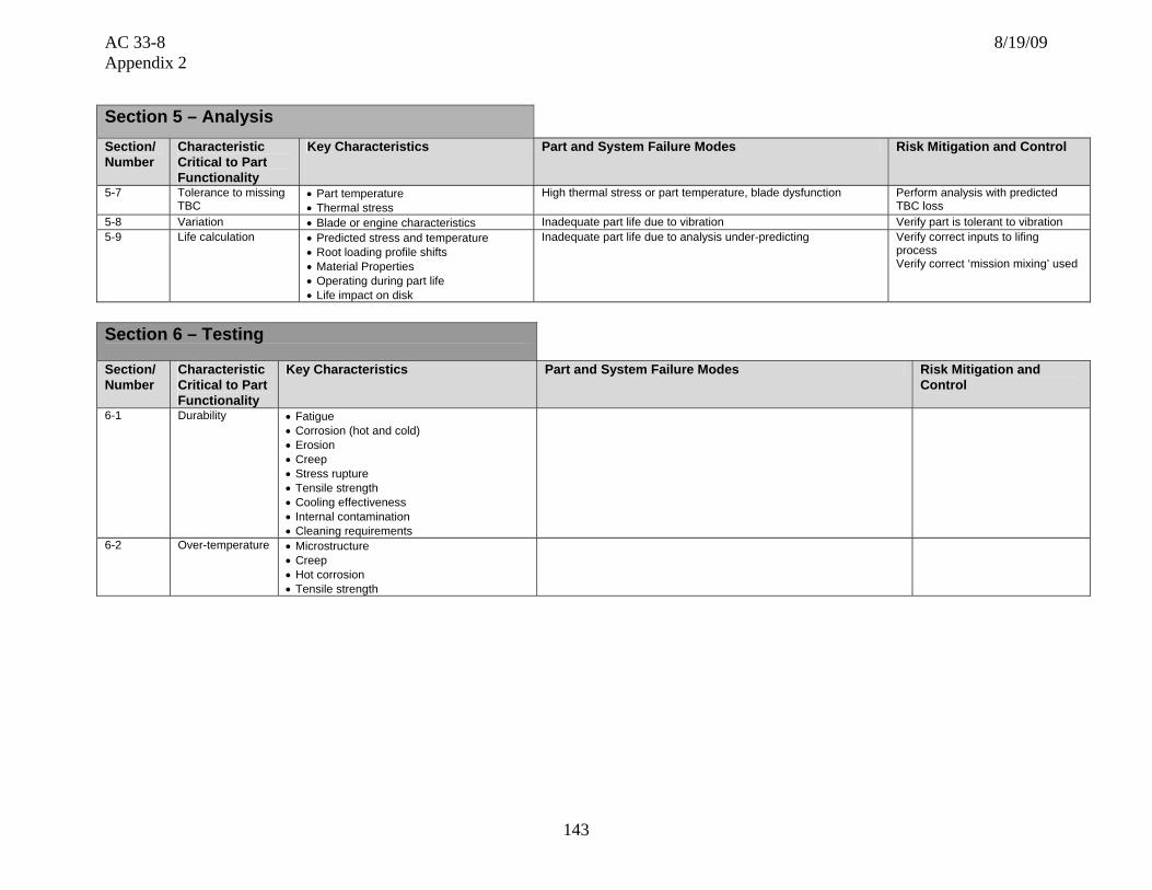
AC 33-8 8/19/09 Appendix 2
143
Section 5 – Analysis Section/ Number
Characteristic Critical to Part Functionality
Key Characteristics Part and System Failure Modes Risk Mitigation and Control
5-7 Tolerance to missing TBC
• Part temperature • Thermal stress
High thermal stress or part temperature, blade dysfunction Perform analysis with predicted TBC loss
5-8 Variation • Blade or engine characteristics Inadequate part life due to vibration Verify part is tolerant to vibration 5-9 Life calculation • Predicted stress and temperature
• Root loading profile shifts • Material Properties • Operating during part life • Life impact on disk
Inadequate part life due to analysis under-predicting Verify correct inputs to lifing process Verify correct ‘mission mixing’ used
Section 6 – Testing
Section/ Number
Characteristic Critical to Part Functionality
Key Characteristics Part and System Failure Modes Risk Mitigation and Control
6-1 Durability • Fatigue • Corrosion (hot and cold) • Erosion • Creep • Stress rupture • Tensile strength • Cooling effectiveness • Internal contamination • Cleaning requirements
6-2 Over-temperature • Microstructure • Creep • Hot corrosion • Tensile strength

AC 33-8 8/19/09 Appendix 2
144
Section 7 – Potential Impact on Regulatory Requirements
Note: The regulatory requirements identified below, which are inclusive up to Amendment 20 of 14 CFR part 33, are intended as a guide to applicants when determining the applicable regulations to which they must show compliance. Those requirements listed as “Could be affected” highlight the regulations whose compliance findings are typically affected by the component or part that this template is addressing. This guide is not all-inclusive and the applicant remains responsible for identifying the certification basis of the product on which their PMA part is to be installed.
Applicable 14 CFR Part 33 Regulatory
Requirements Comments
Subpart A General
1. 33.4 Instructions for Continued Airworthiness Could be affected ICAs including on-wing inspection requirements and on-wing limits
2. 33.5 Instruction manual for installing and operating the engine
3. 33.7 Engine ratings and operating limitations
4. 33.8 Selection of engine power and thrust ratings
Subpart B – Design and Construction;
General
5. 33.14 Start-stop cyclic stress (low cycle fatigue) Could be affected Weight and center-of-gravity affect on rotor forces and LCF Capability
6. 33.15 Materials Could be affected
7. 33.17 Fire prevention
8. 33.19 Durability Could be affected
9. 33.21 Engine cooling
10. 33.23 Engine mounting attachments and structure
11. 33.25 Accessory attachments
12. 33.27 Turbine, compressor, fan, and turbo-supercharger rotors
Could be affected Weight affect on rotor forces during over-speed
13. 33.28 Electrical and electronic control systems
14. 33.29 Instrumentation connection

AC 33-8 8/19/09 Appendix 2
145
Subpart E – Design and Construction; Turbine Aircraft Engines
15. 33.62 Stress analysis Could be affected
16. 33.63 Vibration Could be affected Blade vibration-Design
17. 33.65 Surge and stall characteristics Could be affected Turbine effective area-Operating line migration, Blade-Rub strip interaction
18. 33.66 Bleed air systems
19. 33.67 Fuel system
20. 33.68 Induction system icing (Operability aspects)
21. 33.69 Ignition system
22. 33.71 Lubrication system
23. 33.72 Hydraulic actuating system
24. 33.73 Power or thrust response Could be affected Turbine efficiency/performance
25. 33.74 Continued rotation
26. 33.75 Safety analysis Could be affected Turbine blade release-Case containment
27. 33.76 Bird ingestion (Operability aspects of ingestion)
28. 33.77 Foreign object ingestion (Operability aspects of ingestion)
29. 33.78 Rain and hail ingestion
30. 33.79 Fuel burning thrust augmenter
Subpart F – Block Tests; Turbine Aircraft
Engines
31. 33.83 Vibration test Could be affected Blade vibration-
32. 33.85 Calibration tests
33. 33.87 Endurance test Could be affected Blade durability
34. 33.88 Engine over temperature test Could be affected Blade over temperature capability
35. 33.89 Operation test

AC 33-8 8/19/09 Appendix 2
146
36. 33.90 Initial maintenance inspection Could be affected Blade in-service inspection limits
37. 33.91 Engine component tests
38. 33.92 Rotor locking tests
39. 33.93 Teardown inspection
40. 33.94 Blade containment and rotor unbalance tests (Weight changes)
Could be affected Failure of the most critical turbine blade while operating at maximum permissible r.p.m.
41. 33.95 Engine-propeller system tests
42. 33.96 Engine tests in auxiliary power unit (APU) mode
43. 33.97 Thrust reversers
44. 33.99 General conduct of block tests
45. Part 33 - Appendix A – Instructions for Continued
Airworthiness Could be affected
46. Part 33 - Appendix B - Certification Standard Atmospheric Concentrations of Rain and Hail

AC 33-8 8/19/09 Appendix 2
147
Template #17: Fuel Filter
This template deals with fuel filters which are typically procured under an OEM part number. If the part is listed as a standard part and can be procured commercially, these requirements do not apply.
Nomenclature for Generic Component Features
(all features may not be applicable)
Overall height
Overall diameter
End caps (typical)
Seal/seal glands
Media support mesh
Filtration media assembly
Media support
Anti-rotation tang (typical)
Epoxy bonds (typical)

AC 33-8 8/19/09 Appendix 2
148
Section 1 – Part Functional capability, i.e., the action(s) that the part is designed to perform in the product Section/Number
Characteristic Critical to Part Functionality
Key Characteristics Part and System Failure Modes Risk Mitigation and Control
1-1
Seal glands • Form • O-ring squeeze • Gland fill/ free volume • Surface finish • Edge condition
• Prevent filter bypass • Seal damage/self generated contamination • Anti-rotation friction • Maintenance/seal installation damage
• Dimensional process control and inspection
1-2 Element length • Form/fit • Seal engagement with filter bowl and manifold • Inadequate filter bowl/manifold thread engagement • External leak/failure • Excessive end play/seal wear
• Dimensional process control and inspection
1-3 End caps • Seal gland inside diameter • Upper/lower seal gland concentricity • Support core/end cap fit
• Installation damage( upper seal blind assembly) • Maintenance error/inadequate bowl to manifold
engagement • Material joining/epoxy joint geometry
• Dimensional process control and inspection
1-4 Anti-rotation tang • Form • Position
• Installation damage • Excessive wear-self generated contamination
• Dimensional process control and inspection
1-5 Element diameter • Filter element/filter bowl clearance • Fluid velocity/ flow distribution • Increased pressure drop • Increased filter rotation/ spinning forces
• Dimensional process control and inspection

AC 33-8 8/19/09 Appendix 2
149
Section 2 – Part Shape, size, dimensions and other physical measurable parameters, and interconnectivity with an engine integral part/systemSection/Number
Characteristic Critical to Part Functionality
Key Characteristics Part and System Failure Modes Risk Mitigation and Control
2-1 Filtration rating/ efficiency
Greater than 100 per AIR 887
• Critical orifice blockage/engine control malfunction • Critical valve failure/engine control malfunction • Accelerated component wear /component and engine
failure
• Design capability validation
• Manufacturing acceptance testing
2-2 Filter media surface area/collection sites
Filter element capacity during design basis contamination event following impending bypass indication
• Premature filter bypass/control system malfunction • Design capability validation
2-3 Filter media surface area/collection sites
Filter element capacity during normal contamination. Normal filter life.
• Premature filter bypass/control system malfunction • Design capability validation
2-4 Filet media surface
area Clean element pressure drop • High pressure fuel pump inadequate inlet pressure/
cavitation/inadequate capacity • Design capability
validation • Manufacturing
acceptance testing
Section 3 – Part Materials and Processes – Properties Section/Number
Characteristic Critical to Part Functionality
Key Characteristics Part and System Failure Modes Risk Mitigation and Control
3-1 Media mechanical properties
• Long term durability • Media retention/migration
• Self generating/control system malfunction • Release of contamination/control system malfunction
• Design capability validation
3-2 Material joining epoxy
• Long term durability • Fuel compatibility • Temperature capability • Adhesive strength • Ultimate/tensile strength
• Filter element/media failure • Self generating contamination/control system
malfunction
• Design capability validation
3-3 Environmental resistance
• Oxidation and corrosion resistance • Bacterial growth resistance
• Filter element/media failure • Biological growth system fouling • Stress corrosion cracking
• Design capability validation

AC 33-8 8/19/09 Appendix 2
150
Section 4 – Part Materials and Processes – Processing Section/ Number
Characteristic Critical to Part Functionality
Key Characteristics Part and System Failure Modes Risk Mitigation and Control
4-1 Filtration media manufacture
• Chemical/material composition • Drying/baking
• Self generating contamination/control system malfunction
• Release of contaminant/control system malfunction
• Process definition and control
4-2 Material joining epoxy • Surface finish • Surface cleanliness • Epoxy shelf life/batch quantities • Curing process temperature and time control
• Filter element/media failure • Self generating contamination / control
system malfunction
• Process definition and control
• Process sampling/destructive testing
4-3 Filter media mesh sheath • Wire mesh sintering process • Mechanical preparation/ loose ends from mesh • Stabilization/heat treat
• Filter element / media failure • Media sheath failure / self generated
contamination • Stress corrosion cracking
• Process definition and control
4-4 Welding and brazing • Effects on base materials • Weld or braze strength
• Filter element / media failure • Self generating contamination / control
system malfunction
• Process definition and control
• Process sampling/destructive testing
Section 5 – Analysis Section/ Number
Characteristic Critical to Part Functionality
Key Characteristics Part and System Failure Modes Risk Mitigation and Control
5-1 Operating conditions • Inlet fluid velocity distribution • Rotational forces
• Element rotation/spinning • Media distortion/flow impingement effects
• CFD analysis at maximum flow conditions
5-2 Plugged filter crush resistance
• Support core strength • Filter element/media failure • Release of contaminants
• Strength analysis at worst case filter differential pressure with 2X safety margin
5-3 Installation dimensional stack up
• Axial clearance • Full bowl thread
engagement/assured • O-ring fretting/wear minimized • Radial clearance/seal concentricity
upper seal self aligning
• Filter bowl threads not completely engaged /bowl release / thread failure
• Filter crushed during installation / ineffective filtration / self generated contamination
• Dimensional stack-up analyses • “Murphy proofing”
5-4 “Murphy proof” installation
• Filter element can not be reversed or is fully reversible
• Filter bowl threads not completely engaged /bowl release / thread failure
• Filter crushed during installation / ineffective filtration / self generated contamination
• Dimensional stack-up analyses • “Murphy proofing”

AC 33-8 8/19/09 Appendix 2
151
Section 6 – Testing
Section/ Number
Characteristic Critical to Part Functionality
Key Characteristics Part and System Failure Modes Risk Mitigation and Control
6-1 Filter rating/ efficiency
• Greater than 100 per AIR 887 • Critical orifice blockage/engine control malfunction • Critical valve failure/engine control malfunction • Accelerated component wear/component and engine failures
• Design assurance (glass bead test)
• Product acceptance test 6-2 Filter capacity
test • Filter element capacity during severe
contamination event / time from impending bypass indication
• Premature filter bypass/control system malfunction
• Design assurance test • Specific contaminant
makeup, concentration and duty cycle
6-3 Filter durability • No media migration or contaminant release during long term exposure to hot fuel
• Filter element/media failure • Release of contaminants
• Design operating life demonstration at elevated fuel temperatures
6-4 Filter crush test • Support core test • Filter element/media failure • Release of contaminants
• Design assurance test at greater than 2X maximum filter differential pressure
6-5 Clean element pressure drop
• New filter element pressure drop at maximum fuel flow and specified temperature
• High pressure fuel pump inadequate inlet pressure/cavitation/inadequate pumping capacity
• Design assurance test • Product acceptance test

AC 33-8 8/19/09 Appendix 2
152
Section 7 – Potential Impact on Regulatory Requirements
Note: The regulatory requirements identified below, which are inclusive up to Amendment 20 of 14 CFR part 33, are intended as a guide to applicants when determining the applicable regulations to which they must show compliance. Those requirements listed as “Could be affected” highlight the regulations whose compliance findings are typically affected by the component or part that this template is addressing. This guide is not all-inclusive and the applicant remains responsible for identifying the certification basis of the product on which their PMA part is to be installed.
Applicable 14 CFR Part 33 Regulatory
Requirements Comments
Subpart A – General
1. 33.4 Instructions for Continued Airworthiness Could be affected ICAs including on-wing inspection requirements
2. 33.5 Instruction manual for installing and operating the engine
3. 33.7 Engine ratings and operating limitations
4. 33.8 Selection of engine power and thrust ratings
Subpart B – Design and Construction;
General
5. 33.14 Start-stop cyclic stress (low cycle fatigue)
6. 33.15 Materials Could be affected
7. 33.17 Fire prevention Could be affected No fluid leakage
8. 33.19 Durability Could be affected
9. 33.21 Engine cooling
10. 33.23 Engine mounting attachments and structure
11. 33.25 Accessory attachments
12. 33.27 Turbine, compressor, fan, and turbo-supercharger rotors
13. 33.28 Electrical and electronic control systems
14. 33.29 Instrumentation connection

AC 33-8 8/19/09 Appendix 2
153
Subpart E – Design and Construction; Turbine Aircraft Engines
15. 33.62 Stress analysis
16. 33.63 Vibration Could be affected
17. 33.65 Surge and stall characteristics
18. 33.66 Bleed air systems
19. 33.67 Fuel system Could be affected Proper flow at temperature extremes
20. 33.68 Induction system icing (Operability aspects)
21. 33.69 Ignition system
22. 33.71 Lubrication system
23. 33.72 Hydraulic actuating system
24. 33.73 Power or thrust response
25. 33.74 Continued rotation
26. 33.75 Safety analysis
27. 33.76 Bird ingestion (Operability aspects of ingestion)
28. 33.77 Foreign object ingestion (Operability aspects of ingestion)
29. 33.78 Rain hail ingestion
30. 33.79 Fuel burning thrust augmenter
Subpart F – Block Tests; Turbine Aircraft
Engines
31. 33.83 Vibration test
32. 33.85 Calibration tests
33. 33.87 Endurance test Could be affected Proper fuel flow
34. 33.88 Engine over temperature test
35. 33.89 Operation test

AC 33-8 8/19/09 Appendix 2
154
Subpart F – Block Tests; Turbine Aircraft Engines
36. 33.90 Initial maintenance inspection Could be affected Filter condition
37. 33.91 Engine component tests
38. 33.92 Rotor locking tests
39. 33.93 Teardown inspection
40. 33.94 Blade containment and rotor unbalance tests (Weight changes)
41. 33.95 Engine-propeller system tests
42. 33.96 Engine tests in auxiliary power unit (APU) mode
43. 33.97 Thrust reversers
44. 33.99 General conduct of block tests
45. Part 33 - Appendix A – Instructions for Continued
Airworthiness Could be affected
46. Part 33 - Appendix B - Certification Standard Atmospheric Concentrations of Rain and Hail

AC 33-8 8/19/09 Appendix 3
155
APPENDIX 3. REVERSE ENGINEERING DESIGN PROCESS
Reverse engineering requires comprehensive comparative tests and analyses to show the proposed PMA part complies with the applicable requirements of part 33 or the standard defined by TSO C77. An outline of a reverse engineering design process for complex parts is provided below with details at each step. While not all proposed PMA parts require all of these steps, the more complex parts will generally use most of them. 1. Research and Background Processes. a. Visual and dimensional inspection of sample parts (new). b. Service history review (for example, service bulletins, service difficulty reports (SDRs) and Airworthiness Directives (ADs)). c. Review of field returned parts (for example, for wear, cracking and erosion). d. Define interfaces (such as datum structure and fits and clearances). e. Patent review (consider unique, novel, or subtle design features not detected through the typical reverse engineering process). f. ICA review (such as cleaning, inspection, key features, repairs and fits and clearances). g. Similar part drawing review (PMA holder or public domain). h. Public domain material specification (such as Aerospace Material Specifications and Mil Handbooks). i. International standards for drawings (such as the American Society of Mechanical Engineers). j. Standard part drawings (such as gears, fasteners and bearings). k. Manufacturing technology and sources available to produce the part. l. Discrepancy review versus available data (outside serviceable limits). m. Quality evaluation report (quality differences related to the type design suppliers).
2. Technical Data Generation Processes: a. Dimensions and tolerances (part and mating parts as required). b. Interface definition.

AC 33-8 8/19/09 Appendix 3
156
c. Surface finish. d. Break edges and chamfers. e. Stack-up Analysis. f. Hidden features (those features lost during assembly or processing of the detail parts). g. Materials. These include:
• Micro and macrostructure; • Coatings; • Plating; • Material forms (such as bar stock, forging and casting); and • Material chemistry including trace element requirements.
h. Performance specifications (such as loads, fatigue life and duty cycle). i. Testing specifications (acceptance tests, functional tests). j. Non-destructive testing requirements (such as fluorescent penetrant inspection and ultrasonic). k. Surface enhancements (such as shot peening). l. Non-conventional machining assessment (such as EDM, laser drilling and chemical milling). m. Quality requirements (creation of the preliminary inspection plan). n. Manufacturing process control requirements (substantiated and controlled processes such as material melt practices, plating, heat treat, welding and brazing).
3. Design Verification Processes: a. Final independent design review. b. Conformity inspection of prototypes. c. Testing (functional, operational, and system tests). d. Inspection and quality assurance requirements. e. Complete technical data package with test results. f. Dimensional comparison of prototype with drawing and type design part.

AC 33-8 8/19/09 Appendix 3
157
g. Visual comparison or prototype with type design part. h. Fit-check comparison with type design part. i. Weight comparison with type design parts. j. Part marking review. 4. Project Implementation including:
• Define procurement requirements (for example, special quality clauses); • Supplier selection and approval; and • Delivery of first articles and conformity inspections.

AC 33-8 8/19/09 Appendix 4
158
APPENDIX 4. CONTINUED OPERATIONAL SAFETY
1. Continued Operational Safety is a closed-loop technical and logistical support system that ensures the continued safety of a part and subsequently the product on which it is installed, throughout its lifetime. This support system includes three fundamental elements:
• Prevention; • Data collection and monitoring; and • Response and resolution.
2. The closed-loop system and the relationship between the three fundamental elements are shown in figure A4.1 below:
Figure A4.1: Fundamental Elements of Continued Operational Safety
3. The prevention element is intended to preclude in-service problems before they have a chance to occur. The prevention element includes those activities and processes that are applied during the part design, certification, and manufacturing stage to ensure the design is adequate; the certification is thorough; and the manufacturing is controlled. PMA applicants establishing a COS plan should include procedures that address the following: a. Internal Audits. Internal audits are used to monitor compliance with required airworthiness standards and procedures to ensure production of airworthy components. The audit must include detailed reviews of all Aircraft Certification Systems Evaluation Program (ACSEP) and Principal Inspector (PI) audit results and any reports made to satisfy § 21.3. The auditing procedures should have a feedback reporting system to ensure that proper and timely
Prevention
Data Collection and
Monitoring
Response and
Resolution
Design, Certification & Manufacturing
Service Reliability, Trending, Usage & Part Failures
Lessons Learned Feedback Loop
Investigation, Analysis, Risk Mitigation, Corrective Action
AC 33-8 8/19/09 Appendix 4
159
corrective action is taken in response to reports resulting from the independent audits. Another organization or person with appropriate technical knowledge and experience is often used to conduct the audit. b. Part Field Experience. The following sources are available to evaluate part field experience:
• Service difficulty reports (SDRs) (located at: http://av-info.faa.gov/sdrx/); • Pertinent airworthiness directives (ADs); and • Available ICA (including overhaul instructions, illustrated parts catalogs, and service
bulletins (SB)) should also be reviewed. (1) Operators and maintenance providers may also have service experience with the part, next higher assembly, or both. Surveying these operators and maintenance providers may be useful to confirm the findings of any SDR, Alert SB, SB, or AD review. c. Design Review and Safety Analysis Process. The safety analysis process is a systematic review of a design at appropriate stages. The process can identify any potential failure, malfunction, or defect and considers the impact on the part, the next higher assembly, interface features, airworthiness characteristics, manufacturing controls, and inspection plans. This information can be used to establish preventative action. The process also evaluates the effectiveness of the preventative action through follow-on reviews. Participants in these reviews should include representatives of functions concerned with the design under review. Records of review and subsequent actions must be maintained and should include:
• A review of the available ICA and service history evaluation; and • A safety assessment of the PMA part.
d. Part Development Planning Process. For critical and complex parts, the process focuses on structuring the design effort into significant elements to ensure part safety and reliability. The elements include: (1) A design and development plan; (2) A review, verification, and validation process appropriate to each design and development stage; (3) The responsibilities and authorities for design and development; (4) A means to record project communication; and (5) Recording of design and development inputs related to part requirements (inputs should include functional and performance aspects, statutory and regulatory requirements, and information gathered from similar designs).

AC 33-8 8/19/09 Appendix 4
160
e. Manufacturing Process Change Control and Substantiation. To ensure part safety and reliability, applicants utilizing a COS plan should consider a system to control manufacturing processes. Such a system requires that each process be performed by qualified personnel in accordance with approved specifications containing definitive quality standards. Certain parts may need engineering source approval (controlled or frozen manufacturing processes) of changes to the manufacturing process or inspection system, or both. Substantiation for a proposed process change may include functional or destructive testing, or both. 4. The data collection and monitoring element includes those activities and processes focused on the collection, assimilation, and interpretation of data related to in-service part performance, for example, reliability, trending and usage. It consists of the following procedures: a. Closed Loop Process for all Field Inquiries. This process is used to review, evaluate, and respond to inquiries or notifications of potential service problems from aircraft operators, maintenance service providers, or the FAA. This process includes a list of individuals or organizations within the company with defined responsibilities for responding to all inquiries and notifications. The process is used to identify appropriate methods and resources to investigate service problems, identify the cause of any service difficulties, develop corrective actions, and implement those actions in a timely manner. The process is also used to define how the resolution and corrective action would be transmitted to the reporting entity, other entities potentially impacted, and the FAA. b. Part-Specific Performance Data Trend Analysis. The data trend analysis process is based on part-specific performance. This process is for a PMA part that is determined during the design phase to have a potential adverse effect on the operational safety of the product if it does not perform as intended. This process should include a means for the PMA holder to track its parts, and receive inspection and qualitative feedback from the part user after the part is removed from service for any reason, including routine maintenance. When possible, input from the product operator regarding part performance relative to the design assumptions should be sought. c. Part Delivery Statistics. This process records the quantity of parts shipped, the shipping date and customer. The records should also contain sufficient information to accurately link each shipped part to its lot number or to a manufacturing order. d. Continuing ICA Review. Continuing ICA review is a procedure to review all available new and revised TC holder’s maintenance instructions and service bulletins, as well as ADs that pertain to each TC holder’s part replaced by a PMA part. This procedure may use periodic searches of new or revised TC holder ICAs for referencing a TC holder part number replaced by a PMA part number. This procedure should include a list of qualified individuals or organizations within the company that can determine if any new or revised ICA could potentially affect the performance of their PMA part. The procedure should define the steps needed when it is determined the PMA part is affected by new or revised ICA. 5. The COS plan response and resolution element must include those activities and processes that focus on investigating and analyzing part failures, both actual and precursor; assessing the risks associated with continued operation; identifying and implementing any actions necessary

AC 33-8 8/19/09 Appendix 4
161
to mitigate an unsafe condition; and implementing corrective actions necessary to restore part safety. These activities and processes are: a. Reporting required under § 21.3. Applicants already have this requirement within their FAA-approved fabrication inspection system. AC 21-9A, “Manufacturers Reporting Failures, Malfunctions, or Defects,” and AC 21-1B, “Production Certificates” provide further guidance for reporting under § 21.3. b. Customer Notification Process. This process should include a procedure for the release and control of technical information issued to ensure all necessary parties are aware of a field problem. The notification system may include FAA review. The notification system should include detailed technical instructions for the end user to complete the necessary corrective action. c. Ability to Identify, Develop, and Implement Field Corrective Action Plans. This activity should direct the development and implementation of corrective action plans to address unsafe conditions associated with the part failure. This activity should include a process to communicate with the supply chain and customers so that issues can be tracked and corrective actions implemented. A good reference for this process is AC 39-8, “Continued Airworthiness Assessments of Powerplant and Auxiliary Power Unit Installations of Transport Category Airplanes.” d. Failure Analysis Capability. The PMA holder should be capable of providing a failure analysis of any in-service or manufacturing difficulty. Failure analysis capability demonstrates the applicant understands the part, its interaction with mating parts, its manufacturing processes, and the product and engine. The company should have a policy that demonstrates its understanding of who should complete the failure analysis and how it is disseminated and presented to the FAA, if required. e. Customer Support. The applicant should have the ability to source and manufacture replacement parts to ensure that reliability and safety issues are satisfactorily managed. f. Feedback into Preventative Systems and Procedures. The final step in resolving service difficulties pertains to the lessons learned. We recommend applicants establish feedback to the existing engineering, quality, manufacturing, and safety systems. The objective of feedback is to prevent recurrence of these and similar problems, and, at a minimum, resolve them before an unsafe condition occurs. Feedback can occur through means such as a lessons learned library, training activities, continuous monitoring, and refinement of company processes. The applicant’s management, engineering, manufacturing, and quality departments should be aware of service information that requires changes regardless of the level of safety impacted. The key is to develop, implement, and monitor solutions to resolve problems and prevent future ones from occurring.