Embed Size (px)
Citation preview
1
Advances in three-dimensional rapid prototyping
of microfluidic devices for biological applications
P.F. O’Neill 1,2
, A. Ben Azouz 1,2,3
, M. Vázquez 1,2,a)
, J. Liu 1
, S. Marczak4, Z. Slouka
4,
H.C. Chang4, D. Diamond
3, D. Brabazon
1,2
1Advanced Processing Technology Research Centre, School of Mechanical and
Manufacturing Engineering, Dublin City University, Ireland
2Irish Separation Science Cluster, National Centre for Sensor Research,
Dublin City University, Ireland
3Insight Centre for Data Analytics, National Centre for Sensor Research,
Dublin City University, Ireland
4Centre for Microfluidics and Medical Diagnostics, University of Notre Dame,
Indiana IN 46556, USA
________________________________________
a)Author to whom correspondence should be addressed: Email: [email protected].
Tel: +353 1 700 7602.
2
Abstract
The capability of 3D printing technologies for direct production of complex 3D structures in
a single step has recently attracted an ever increasing interest within the field of
microfluidics. Recently, ultrafast lasers have also allowed developing new methods for
production of internal microfluidic channels within the bulk of glass and polymer materials
by direct internal 3D laser writing. This review critically summarizes the latest advances in
the production of microfluidic 3D structures by using 3D printing technologies and direct
internal 3D laser writing fabrication methods. Current applications of these rapid prototyped
microfluidic platforms in biology will be also discussed. These include imaging of cells and
living organisms, electrochemical detection of viruses and neurotransmitters, and studies in
drug transport and induced-release of adenosine triphosphate from erythrocytes.
I. Introduction
During the past three decades, microfluidic systems have evolved from relatively simple
single-function devices to multiple-function analytical systems1 used for a wide range of
biological applications in clinical and forensic analysis,2 proteomics and metabolomics,
1
immunoassays,3 cell analysis,
1 point-of-care (POC) diagnostics,
1 drug discovery,
4 genetic
analysis,5 and organs-on-chip.
6–9 These micro scale systems have a number of advantages
over traditional macro scale methods used in biological and biomedical research, including
the capability of (i) streamlining complex assay protocols, (ii) providing investigators with
accurate manipulation of the cell microenvironment, and (iii) reducing the sample and
reagent volume maximising the information obtained from precious samples and reducing
costs. However, most of the publications in the field of microfluidics are still appearing in
engineering journals (85% in 2010) compared to biology and medical journals.10
This
3
indicates that there is still a lot of scope for further bio-focused research in microfluidics as
well as for the emergence of new bio application domains in the coming years.
In fact, though microfluidics is widely considered to be a key component in both
development of laboratory-based, high-throughput analytical methods and POC diagnostics, a
“killer application” for microfluidics is still anticipated.11–13
Such an application is one that
will generate large revenue in a relatively short period of time and will strongly promote the
microfluidic industry as a whole. In a recent series of articles by Becker it is suggested that
the diagnostic market is one such area where microfluidics will find its niche.12,13
However,
before this is realised a significant amount of work still needs to be carried out in the area of
design, manufacture, and integration of microfluidic components (e.g. valves, micropumps,
and separation columns) within a single microfluidic platform.14,15
Thus, recent advances in
rapid prototyping (RP) techniques, such as the availability of 3D RP equipment with much
higher resolution, have the ability to propel the field of microfluidics forward towards finding
such a “killer application” by easing the fabrication of complex designs as well as speeding
up the fabrication process allowing for mass production.
3D printing16
and direct internal 3D laser writing17
methods allow for direct fabrication of 3D
microstructures in one single step. In comparison, standard replication methods for
fabrication of microfluidic devices such as injection moulding, hot embossing and casting
(i.e. soft lithography18
) can be termed multistep manufacturing methods as they require the
creation of a replication master before casting or moulding of the final device. These
replication methods, while particularly useful for industrial scale manufacture in the case of
injection moulding, are often expensive and time-consuming on a smaller scale owing to the
4
need for fabrication of the replication master. Alternatively, direct microfabrication methods
such as computer-numerical-control (CNC) milling and 2D laser surface ablation allow for
direct fabrication of microchannels on a variety of substrates, including glass and polymers.
However, all these standard microfabrication methods typically lead to the production of
open channels on the surface of a substrate, which then need to be sealed by an additional
layer creating an enclosed microfluidic channel. Thus, standard microfabrication methods
employed in microfluidics will generally involve a multistep procedure as compared to 3D
printing and direct internal 3D laser writing methods. In this paper, these direct 3D
fabrication methods are presented and their capabilities for fabrication of microfluidic
devices for biological applications are reviewed.
II. 3D printing fabrication methods
The term 3D printing covers a wide range of techniques, some of which are already well
established and widely used in industry. That is the case of stereolithography (SL), also
sometimes referred to as micro-stereolithography (µSL), which is one of the most important
rapid prototyping processes in industry today.19
SL allows for the automated production of
complex 3D shapes in polymeric materials at low to medium volume throughputs.20
SL
presents an inherent advantage over other lithographic methods (i.e. photolithography and
soft lithography) in that no alignment or bonding is necessary to produce 3D structures. SL,
developed by Hull in 1986,21
involves curing a photocurable liquid polymer layer by layer
using a UV light to build up a solid 3D object.
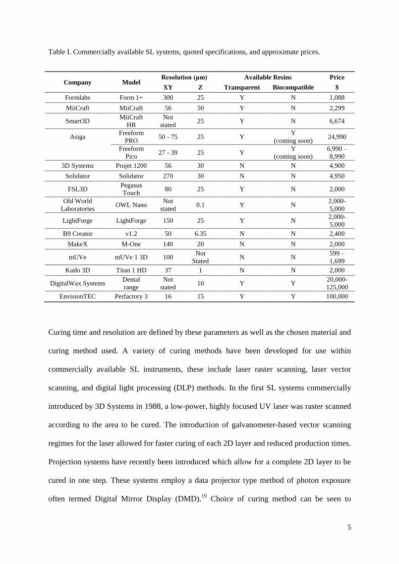
A list of popular commercially available high resolution SL systems and their corresponding
attributes is given in Table I. These systems range from the Form 1+ at the lower end of the
price scale to DigitalWax and EnvisionTEC systems at the higher end. This large discrepancy
in price could be attributed to three main factors: resolution, build area, and build speed.
5
Table I. Commercially available SL systems, quoted specifications, and approximate prices.
Company Model Resolution (μm) Available Resins Price
XY Z Transparent Biocompatible $
Formlabs Form 1+ 300 25 Y N 1,088
MiiCraft MiiCraft 56 50 Y N 2,299
Smart3D MiiCraft
HR
Not
stated 25 Y N 6,674
Asiga Freeform
PRO 50 - 75 25 Y
Y
(coming soon) 24,990
Freeform
Pico 27 - 39 25 Y
Y
(coming soon)
6,990 –
8,990
3D Systems Projet 1200 56 30 N N 4,900
Solidator Solidator 270 30 N N 4,950
FSL3D Pegasus
Touch 80 25 Y N 2,000
Old World
Laboratories OWL Nano
Not
stated 0.1 Y N
2,000-
5,000
LightForge LightForge 150 25 Y N 2,000-
5,000
B9 Creator v1.2 50 6.35 N N 2,400
MakeX M-One 140 20 N N 2,000
mUVe mUVe 1 3D 100 Not
Stated N N
599 –
1,699
Kudo 3D Titan 1 HD 37 1 N N 2,000
DigitalWax Systems Dental
range
Not
stated 10 Y Y
20,000-
125,000
EnvisionTEC Perfactory 3 16 15 Y Y 100,000
Curing time and resolution are defined by these parameters as well as the chosen material and
curing method used. A variety of curing methods have been developed for use within
commercially available SL instruments, these include laser raster scanning, laser vector
scanning, and digital light processing (DLP) methods. In the first SL systems commercially
introduced by 3D Systems in 1988, a low-power, highly focused UV laser was raster scanned
according to the area to be cured. The introduction of galvanometer-based vector scanning
regimes for the laser allowed for faster curing of each 2D layer and reduced production times.
Projection systems have recently been introduced which allow for a complete 2D layer to be
cured in one step. These systems employ a data projector type method of photon exposure
often termed Digital Mirror Display (DMD).19
Choice of curing method can be seen to
6
depend on the specific application with vector scanning typically providing a larger build
volume (e.g. Form 1+) compared to DLP methods which provide increased productivity (e.g.
EnvisionTEC Perfactory 3). Most commercial systems sold today offer the ability to adjust
the resolution to speed up productivity (lower resolution resulting in faster build speeds),
while in some cases the lens can be changed to improve resolution further, sacrificing build
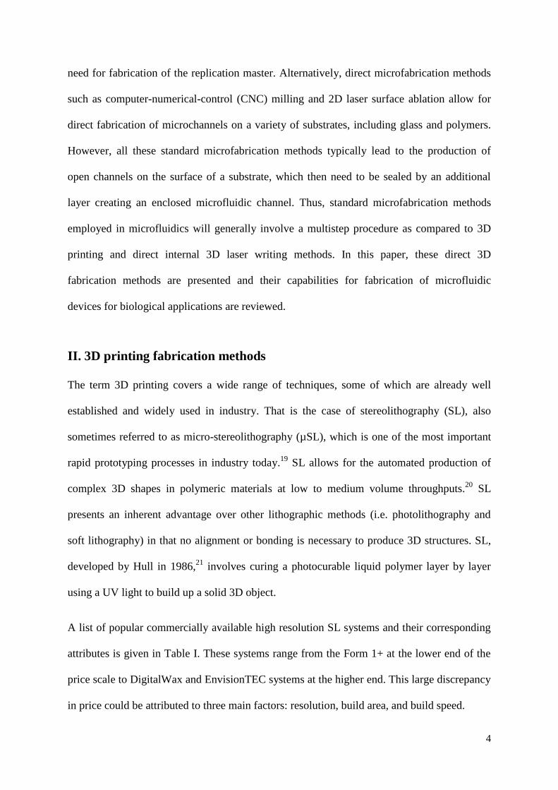
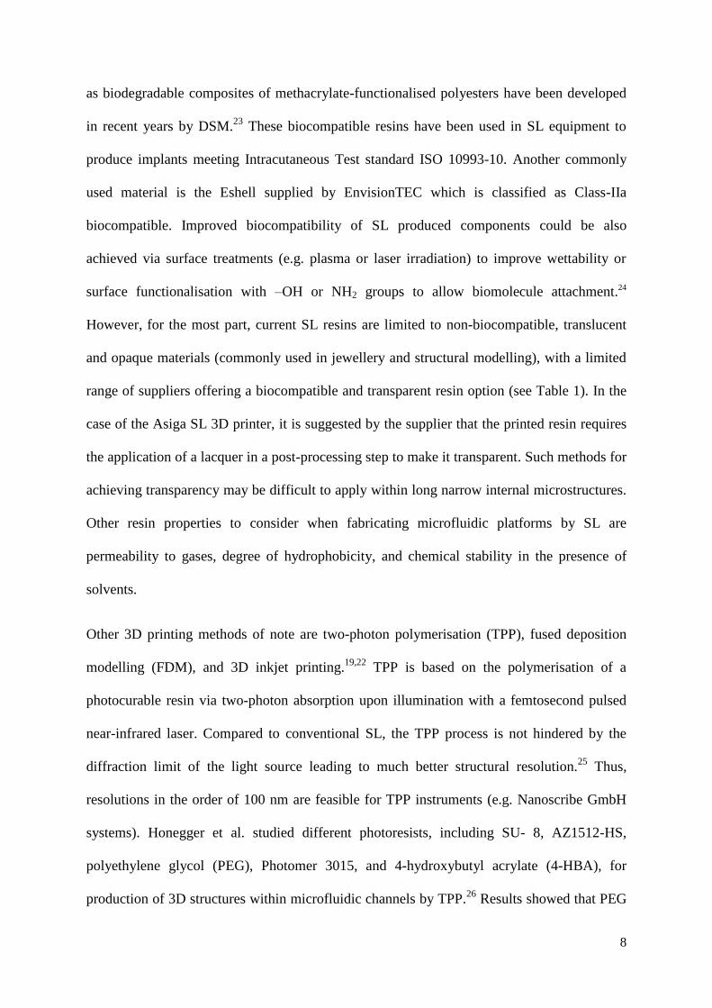
area as a result (e.g. EnvisionTEC’s Perfactory 3 Mini Multi Lens). Figure 1 shows a
schematic representation of these two different curing approaches, i.e. direct laser writing
(Figure 1(a)) and DMD-based writing (Figure 1(b)).22
In addition, two different
configurations are also possible depending on the orientation of the light source: the bath
configuration (Figure 1(a)) and the layer configuration (Figure 1(b)). In the bath
configuration the part is built from the bottom up, with the z-stage moving down into the
resin vat after each layer has been cured to start building the next layer. The layer
configuration uses a light source situated beneath the z-stage which cures the part through an
optically transparent window beneath the resin vat. After each layer has been cured, the z-
stage moves upwards producing a part that is “upside down” when finished. Of these two
configurations, the layer configuration is the most popular as the part height is not restricted
by the size of the vat, there is less resin waste, and the layer thickness can be more readily
controlled by the z-stage positioning as opposed to controlling the laser depth of focus.22
7
FIG. 1. (a) Schematic of a SL bath configuration with direct laser writing and (b) a SL layer
configuration with DMD-based writing. Reprinted with permission from Gross et al., Anal. Chem.
86(7), 3240 (2014). Copyright 2014 American Chemical Society
Folch et al. recently investigated the capabilities of SL methods for fabrication of
microfluidic systems 20
. They found that the main limiting factors were the effective drainage
of the uncured liquid resin, optical clarity, and z-height resolution. Current research and
development into photocurable and SL systems aims to overcome these limitations focusing
toward the implementation of new advanced resins and improvement in the xy- and z- system
resolutions. Table I presents an overview of a broad range of currently available SL systems,
and their capabilities and prices as provided by the manufacturers. New resins exhibiting
improved optical transparency and biocompatibility are also continuously being introduced to
the market, which no doubt will favour further applications of 3D printing in microfluidic-
based biological assays/platforms with optical detection/imaging. For example, biostable
resins based on polyester/polyether oligomers with acrylate or methacrylate functions, as well
(a) (b)
8
as biodegradable composites of methacrylate-functionalised polyesters have been developed
in recent years by DSM.23
These biocompatible resins have been used in SL equipment to
produce implants meeting Intracutaneous Test standard ISO 10993-10. Another commonly
used material is the Eshell supplied by EnvisionTEC which is classified as Class-IIa
biocompatible. Improved biocompatibility of SL produced components could be also
achieved via surface treatments (e.g. plasma or laser irradiation) to improve wettability or
surface functionalisation with –OH or NH2 groups to allow biomolecule attachment.24
However, for the most part, current SL resins are limited to non-biocompatible, translucent
and opaque materials (commonly used in jewellery and structural modelling), with a limited
range of suppliers offering a biocompatible and transparent resin option (see Table 1). In the
case of the Asiga SL 3D printer, it is suggested by the supplier that the printed resin requires
the application of a lacquer in a post-processing step to make it transparent. Such methods for
achieving transparency may be difficult to apply within long narrow internal microstructures.
Other resin properties to consider when fabricating microfluidic platforms by SL are
permeability to gases, degree of hydrophobicity, and chemical stability in the presence of
solvents.
Other 3D printing methods of note are two-photon polymerisation (TPP), fused deposition
modelling (FDM), and 3D inkjet printing.19,22
TPP is based on the polymerisation of a
photocurable resin via two-photon absorption upon illumination with a femtosecond pulsed
near-infrared laser. Compared to conventional SL, the TPP process is not hindered by the
diffraction limit of the light source leading to much better structural resolution.25
Thus,
resolutions in the order of 100 nm are feasible for TPP instruments (e.g. Nanoscribe GmbH
systems). Honegger et al. studied different photoresists, including SU- 8, AZ1512-HS,
polyethylene glycol (PEG), Photomer 3015, and 4-hydroxybutyl acrylate (4-HBA), for
production of 3D structures within microfluidic channels by TPP.26
Results showed that PEG
9
and 4-HBA were suitable materials for production of arm structures within channels with
submicrometer resolution.
FDM is based on the extrusion of melted bulk material through a heated nozzle.27
As with the
other 3D printing technologies, each 2D layer is traced out with subsequent layers being
added to build up the required 3D design. Common materials used in the FDM process
include acrylonitrile butadiene styrene (ABS), polylactic acid (PLA), and nylon. FDM
printers can write in many colours/materials without the need for changing the filament
between colours/materials by usage of multiple extrusion nozzles. Due to the nature of the
printing process, the resolution achievable is limited by the xy-plotter (two stepper motors),
the z-stepper motor, the thickness of the filament, and the extrusion nozzle diameter. FDM
printers are widely available from companies such as RepRap, Ultimaker, MakerBot, and 3D
Systems. Finally, 3D inkjet printing involves applying droplets of bonding resin according to
a prescribed 2D design onto powder to bond each 2D layer. The 2D layer of bound and
unbound powder provides support for the subsequent layer. In an alternate 3D inkjet printing
process, a low viscosity photocurable resin is printed alongside a support material such as
wax onto the build platform. The wax support material acts as a mould, constraining the
liquid resin until it is hardened during the curing stage. As with other 3D printing methods,
this process is repeated, layer by layer, until the part is finished. A post-processing step is
then required to remove the unbound powder or wax support material.
III. Direct internal 3D laser writing fabrication methods
Direct internal 3D laser writing methods have been recently employed for fabrication of
channels and other micro features (e.g. optical components) in microfluidic devices. These
methods consist in the internal processing of in-bulk materials by laser ablation using
ultrashort-pulsed lasers with low pulse energy.17
These ultrafast lasers, having pulse widths in
10
the pico- to femtosecond range, can produce high quality microstructures within glass and
polymer materials owing to a significant reduction in the heat-affected zone (HAZ)
surrounding the ablation focal position with decreased pulse width. Femtosecond lasers (e.g.
800 nm Ti:sapphire), in particular, can modify materials at wavelengths for which they are
normally transparent. This occurs by depositing energy through high-order non-linear
absorption processes inducing optical breakdown, which makes these lasers very useful tools
for micromachining.28
Femtosecond lasers also offer the possibility to produce sub-
wavelength features as these non-linear absorption processes are not limited by optical
diffraction.29
A major disadvantage of these ultrafast laser systems to date has been their cost,
with femtosecond lasers typically being three to six times more expensive than standard
nanosecond CO2, excimer or Nd:YAG systems of similar power.
In 1996, Davis et al. showed that it was possible to write 3D structures for fabrication of
optical waveguides in different bulk glasses, including silica and soda-lime, via multiphoton
interactions with femtosecond laser radiation.30
A procedure for fabrication of 3D
interconnected channels as narrow as 10 m inside silica was then presented in 2001.31
It
consisted in optical damaging of bulk silica by a 795 nm femtosecond laser, followed by
selective etching of the written structures with hydrofluoric acid (HF) solutions.
Photosensitive glasses such as Foturan haven been also employed for production of 3D U-
shaped microchannels following infrared femtosecond exposure.32
Femtosecond irradiation
induces a local phase change in this phosensitive glass, from amorphous to crystalline. This
process was then completed by heating and subsequent etching of the crystalline areas with
10% HF solution. Recently, internal processing of polymethyl methacrylate (PMMA),
polydimethylsiloxane (PDMS), polystyrene (PS), and polyvinyl alcohol (PVA) polymers has
also been investigated.33
A 800 nm Ti:sapphire laser with a maximum pulse energy of 1 mJ
was used in this work.
11
IV. Applications in biology
Microfluidic systems are very valuable tools for fundamental studies of complex biological
systems since they provide precise control of small volumes of fluids over very short
distances. Flow cytometry analysis,34
cell-based assays (such as cytotoxicity35
or induced
cellular stress assays36
), sorting, manipulation and imaging of single-cells,37
and cell/tissue
engineering,38,39
are just some of the current applications of microfluidics in biology.
Microfluidics also offer the means to create and maintain environments that closely resemble
those encountered in vivo.40,41
This is essential in ensuring that the experimental results are
not biased with artefacts caused by, for example, early triggered apoptosis and, therefore,
creating the right environment has important implications in cell analysis. Moreover, current
microfabrication techniques allow the production of large arrays of microwells that can
entrap single/multiple cells to perform molecular analysis,42
or study cell response to
chemical and physical stimuli following exposure to different environments;43
the major
advantage of this approach being the ability to perform parallel screening of a large number
of cells.
In addition, one of the main advantages of 3D printing over more conventional techniques
typically employed for production of biomicrofluidic devices is the simplification of the
process which does not require the fabrication of a replication master nor extensive
labour.19,20,22,44
A 3D microvascular network enabling chaotic mixing was one of the earliest
microfluidic devices produced by 3D printing more than 10 yr ago.45
The microfluidic mixer
integrating cylindrical channels with diameters between 10 μm and 300 μm was fabricated by
direct-write assembly of a fugitive organic ink. Sixteen-layer scaffolds were first produced by
robotic deposition of a paraffin-based organic ink, followed by infiltration with an epoxy
resin, and subsequent curing of the resin at 22 °C and ink removal at 60 °C. A photocurable
resin was then infiltrated in the resulting microchannels and polymerised through a photo-
12
mask for production of the final interconnected network. The efficiency of the 3D mixer was
then tested by mixing two fluorescent dyes (red and green) as a function of varying Reynolds
numbers (Re). Alternatively, direct printing of fugitive ink filaments within a photocurable
gel reservoir recently allowed the fabrication of a 3D microvascular network for potential
applications in 3D cell culture, tissue engineering, and drug delivery. Subsequent
photopolymerisation of the gel (Pluronic F127 diacrylate) and removal of the fugitive ink led
to the generation of the microvascular network within the hydrogel matrix.46
Inkjet printing
has also been used for generation of 3D hydrogel scaffolds with embedded microchannels for
adequate supply of nutrients and oxygen to cells in tissue engineering applications.47
An in-
house 3D printer capable of dispensing a chemically crosslinkable collagen hydrogel
precursor, a heated gelatin solution (used as the sacrificial element for channel fabrication)
and cell suspensions, allowed the generation of a 3D collagen scaffold with microfluidic
channels capable of performing adequate perfusion of cells printed inside the scaffold.47
In comparison to the above multi-step 3D printing methods, a one-step procedure was
recently applied to the fabrication of optically transparent microfluidic devices using
stereolithography.20,44
These optically transparent chips were successfully employed in
imaging of Chinese hamster ovary (CHO) cells previously seeded within the microchannels.20
Albeit a certain degree of autofluorescence was exhibited by the biocompatible resin
employed in the chip fabrication, discrete cells were clearly observed under fluorescence as
well as phase-contrast modes. The capability of stereolithography for direct integration of
standard connectors to the macro-world within the final device was also demonstrated (e.g.
female Luer connectors20
and 10-32 threads44
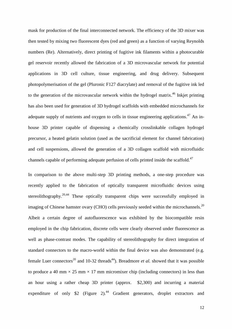
). Breadmore et al. showed that it was possible
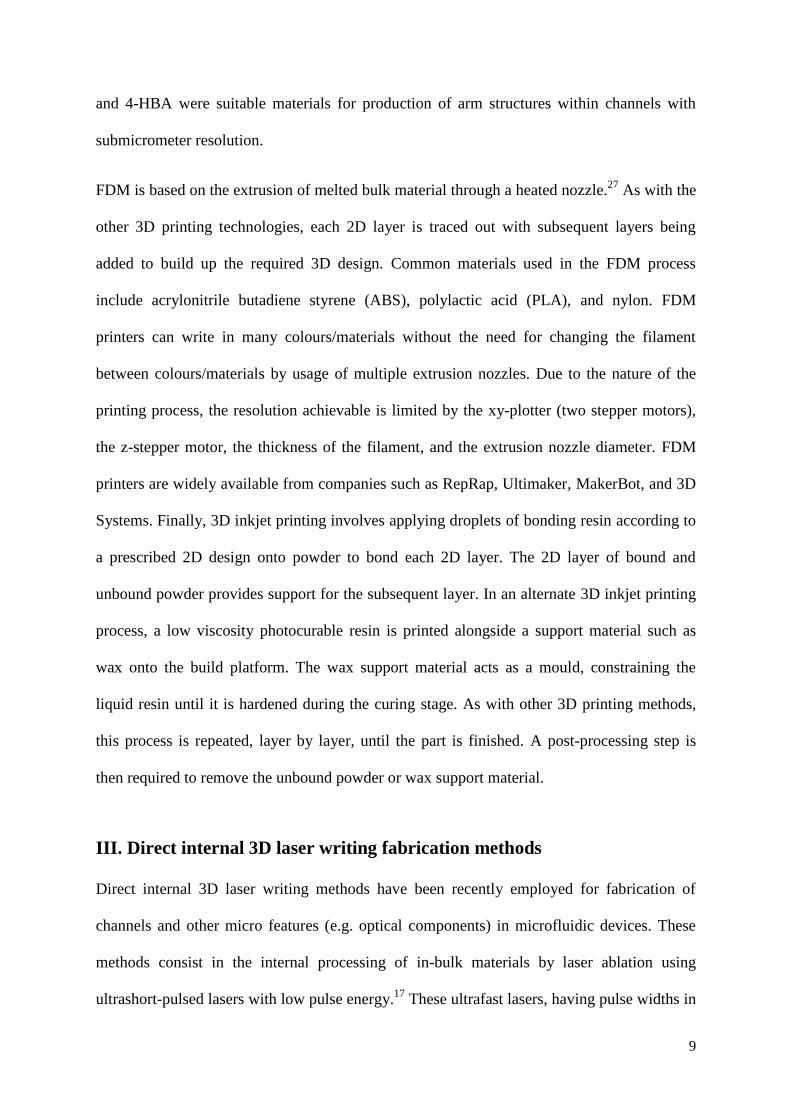
to produce a 40 mm × 25 mm × 17 mm micromixer chip (including connectors) in less than
an hour using a rather cheap 3D printer (approx. $2,300) and incurring a material
expenditure of only $2 (Figure 2).44
Gradient generators, droplet extractors and
13
isotachophoresis chips were also successfully generated with the same 3D printer confirming
the feasibility of this approach for cost-effective, rapid prototyping of microfluidic devices,
which could open the door to many future low-cost analytical applications.
FIG. 2. Optically transparent microfluidic mixer chip integrating 10-32 threads. Reprinted with
permission from Shallan et al., Anal. Chem. 86(6), 3124 (2014). Copyright 2014 American Chemical
Society
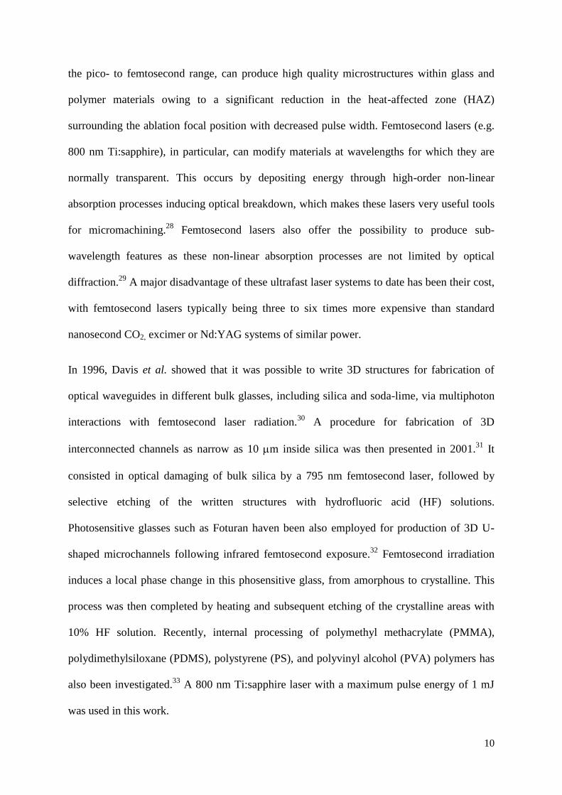
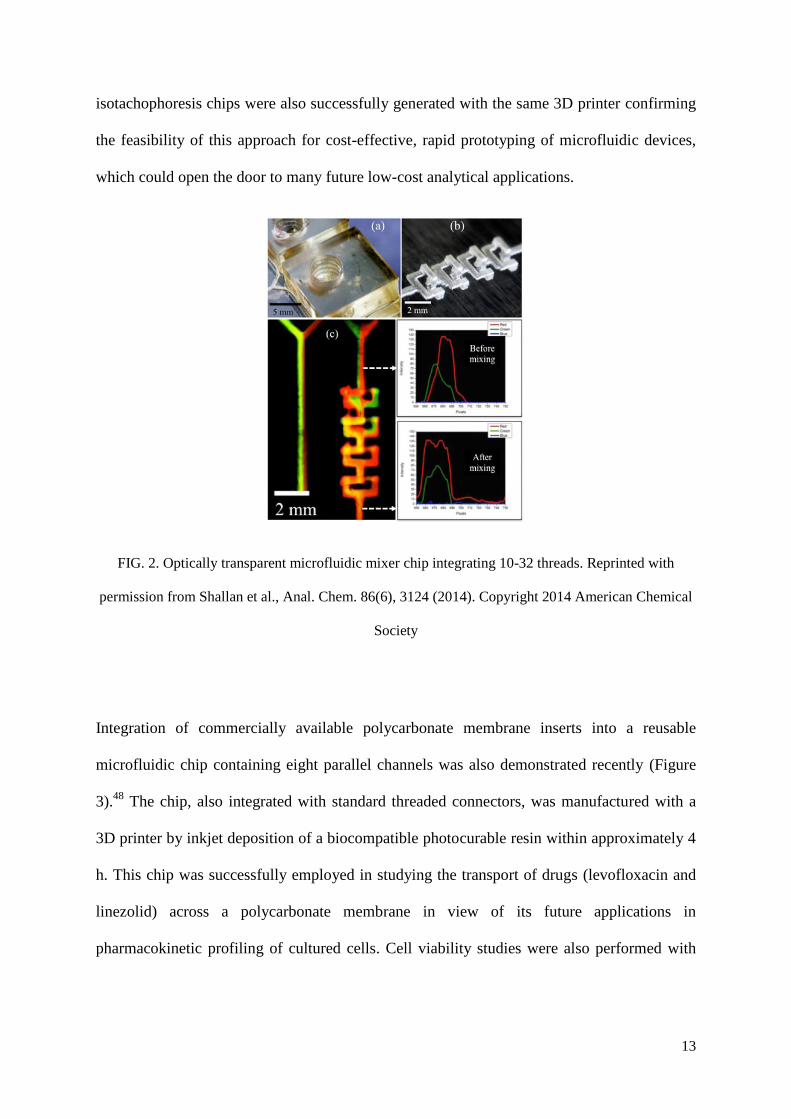
Integration of commercially available polycarbonate membrane inserts into a reusable
microfluidic chip containing eight parallel channels was also demonstrated recently (Figure
3).48
The chip, also integrated with standard threaded connectors, was manufactured with a
3D printer by inkjet deposition of a biocompatible photocurable resin within approximately 4
h. This chip was successfully employed in studying the transport of drugs (levofloxacin and
linezolid) across a polycarbonate membrane in view of its future applications in
pharmacokinetic profiling of cultured cells. Cell viability studies were also performed with
14
this platform via exposure of bovine pulmonary artery endothelial cells to a detergent
(saponin) which was pumped into the channels inducing cell death.
FIG. 3. Microfluidic chip integrating membrane inserts. Reprinted with permission from Anderson et
al., Anal. Chem. 85(12), 5622 (2013). Copyright 2013 American Chemical Society
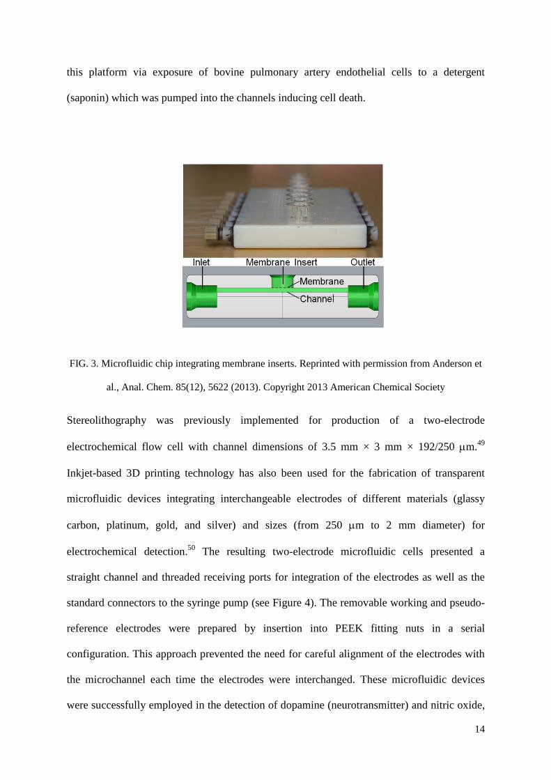
Stereolithography was previously implemented for production of a two-electrode
electrochemical flow cell with channel dimensions of 3.5 mm × 3 mm × 192/250 m.49
Inkjet-based 3D printing technology has also been used for the fabrication of transparent
microfluidic devices integrating interchangeable electrodes of different materials (glassy
carbon, platinum, gold, and silver) and sizes (from 250 m to 2 mm diameter) for
electrochemical detection.50
The resulting two-electrode microfluidic cells presented a
straight channel and threaded receiving ports for integration of the electrodes as well as the
standard connectors to the syringe pump (see Figure 4). The removable working and pseudo-
reference electrodes were prepared by insertion into PEEK fitting nuts in a serial
configuration. This approach prevented the need for careful alignment of the electrodes with
the microchannel each time the electrodes were interchanged. These microfluidic devices
were successfully employed in the detection of dopamine (neurotransmitter) and nitric oxide,
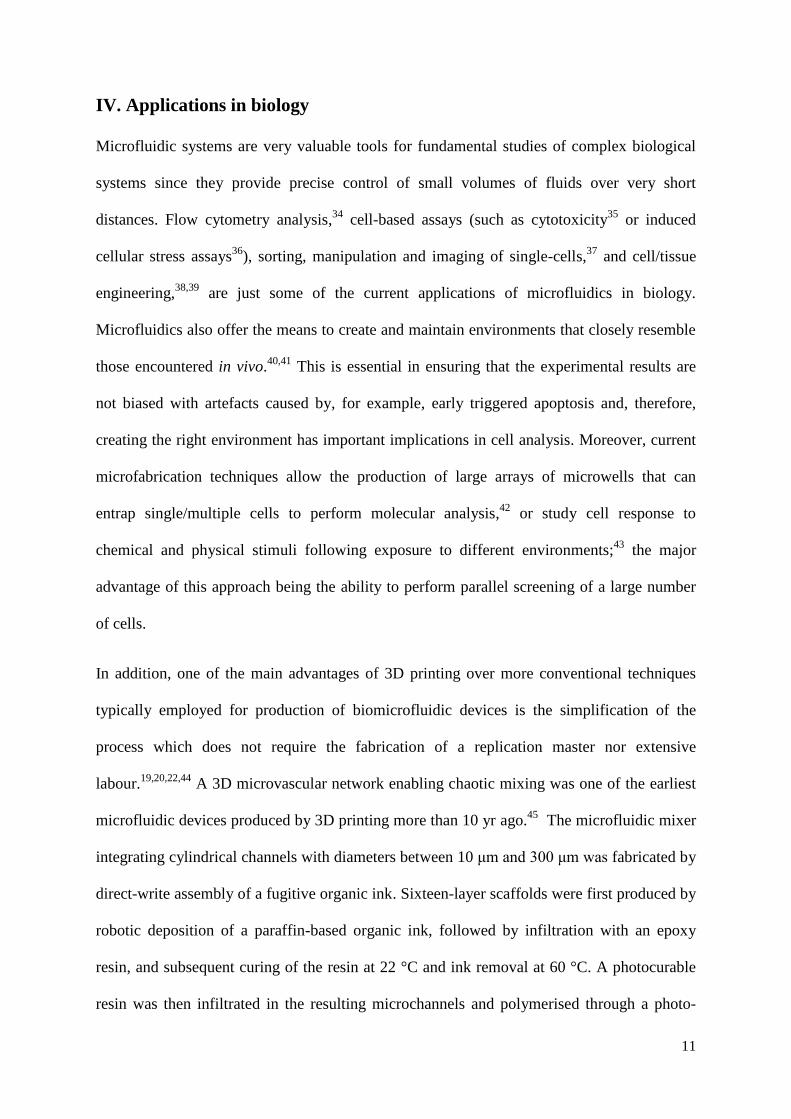
Upon insertion of themembrane insert, buffer wasadded to theinsert and the standard solutions were pumped through thechannels for an hour at 1 μL/ min. After an hour, liquid wassampled from the insert and added to a vial containing asolution of acetonitrile and the internal standard, ciprofloxacin.
The samples were then analyzed using LC/ MS/ MS tomonitor the diffusion of linezolid and levofloxacin from thechannel, across the porous membrane. After an hour of flow,the 1.1 and 2 μM samples had between 18.4%and 20.5%drugtransport across the polycarbonate membrane (Figure 2).
Moreover, results yielded reproducible drug transport concen-trations between runs furthering the reusability of the device.Though it was not monitored in this instance, results from ourlab indicate that drug transport can occur from the insert intothe channel; of course, this transport is dependent upon theconcentrations of thedrug in thewell and in thechannel. If the
concentration is higher in the channel, drug moves to the well;if higher in the well (e.g., if agradient isperformed that lowersthe concentration in the channel), then the drug transport isback to the channel. Importantly, every molecule that we havetested to date has similar transport properties, with somedifferences occurring due to size of the molecule or itshydrophobicity.
In other polymer-based devices, reusability is not an optiondue to issues with maintaining seals. Contamination is also aconcern due to challenges in cleaning devices or absorption ofmaterials into the polymer base.20 The use of a new device foreach experiment can lead to high variability between runs. Also,the incorporation of a membrane into the polymer-baseddevice, typically reversibly sealed between two pieces, can beeasily compromised due to the flexibility of the supportmaterial. Cleaning and extended usecan also weaken the fragilemembrane. Many of these problems are minimized with theprinted devices with well inserts.
Cell Viability Assessment. Commercially available cellculture inserts were used to integrate the 3D printed devicewith cultured cells. In this design, the insert clicks into placeabove the channel and the membrane would contain a layer ofcultured cells as shown in Figure 3A. Furthermore, the ECswere stained with Hoechst 33342 dye (ex. 350 nm, em. 460nm), a simple nucleic acid stain to confirm the presence of aconfluent layer of cells on top of the membrane. The image inFigure 3A wasobtained using afluorescence microscope with aDAPI filter, and the stained cells are visualized on top of themembrane.
In order to determine whether this 3D printed device couldbe used to study cellular status, aviability study wasperformedusing a well-known cell detergent and an EC line that is easilycultured onto membrane inserts. Either HBSS or saponin (adetergent used to compromise cell membranes) was flowedthrough the channel under the membrane that containedcultured ECs. It was expected that saponin would diffusethrough the polycarbonate membrane and come into contactwith theECs. Asshown in Figure 3B, theECsthat were treatedwith saponin had a 4-fold increase in fluorescence intensity incomparison to the cells treated with HBSS. The Sytox Greendoes not stain live cells, so the increased fluorescence indicatesa higher population of dead cells. The images from thefluorescence microscope (Figure 3C) confirm this fact, as theimage of thesaponin treated ECsshow more fluorescence thanthe image of ECs treated with HBSS alone.
The aforementioned strains on conventional fluidic mem-branes lend virtue to the cell culture insert as it has a ruggedbase, which supports themembrane and can beeasily discardedafter use. The rigidity of the 3D device when usedsimultaneously with the disposable cell inserts offers asupportive platform for a reusable fluidic device. Of course,many of these same features are available when using static 96-well plate systems. However, in a static system, the user islimited to adding a fixed amount of a drug candidate to cellscultured in a well on a microtiter plate and allowing that fixedamount of drug to interact with the cells for a predeterminedamount of time before removing the drug from the cells inpreparation for further dosing. Theadvantage of the3D printeddevice described here is that each well/ insert can be addressedby a fluidic stream. In this construct, the system now has thepotential to function asadynamic in vitro system; for example,the cells could be subjected to a drug candidate at a desirableconcentration. However, by using gradient pumping schemes,
Figure 1. 3D printed device design. The final 3D printed device, topimage, contains adapters for syringe-based pumps, channels,membrane insertion port, and outlets. The side view schematic ofthe device shows how the inlet addresses the channel and allows fluidto flow under themembrane. Themembrane ispart of acommerciallyavailable membrane insert that is manually inserted into the port ontop of the device. Finally, there is an outlet to allow fluid to leave thedevice.
Figure 2. Drug transport across a membrane. Standards of the drugslinezolid (N = 4) and levofloxacin (N = 5) were flowed through thechannels of the device; samples were collected above the membraneand analyzed viaLC/ MS/ MS. Asconcentration of the drug increased,so did transport across the membrane with each concentration beingstatistically different from the previous (p value <0.001). Drugtransport across the membrane was between 18.4% and 20.5%.
Analytical Chemistry Letter
dx.doi.org/10.1021/ac4009594 | Anal. Chem. 2013, 85, 5622−56265624
15
as well as the collection of adenosine triphosphate (ATP) released from red blood cells
flowing through the channels while simultaneously measuring oxygen concentration (release
stimulus). For collection of ATP, polyester membrane inserts were fitted into a couple of well
ports integrated in the device. Collected ATP was then analysed by chemiluminescence
detection.
FIG. 4. Microfluidic chip for electrochemical detection: a–b) schematics of the chip showing the
threaded ports; c) picture showing alignment of both working and pseudo-reference electrodes with
the channel; d) picture showing the chip connected to the syringe pump. Reprinted with permission
from Erkal et al., Lab Chip 14(12), 2023 (2014). Copyright 2014 Royal Society of Chemistry
A microfluidic chip integrating ports for a three-electrode system was recently produced from
PLA by FDM, and was used for specific electrochemical detection of influenza virus.51
Influenza hemagglutinin labelled with CdS quantum dots was first isolated within the
reaction chamber by glycan-modified paramagnetic beads via hemagglutinin-glycan
interaction. Electrochemical quantification of cadmium(II) ions by differential pulse
voltammetry was then carried out to determine the presence of the virus.
16
FDM has also been investigated for fabrication of capillary valves in centrifugal microfluidic
discs.52
Results showed that 3D printing can be considered a viable alternative to other
fabrication techniques typically employed for the fabrication of microfluidic discs (e.g. CNC
milling and soft lithography) in view of their application in the development of biochemical
assays.53
Although channels produced in ABS possessed ridged or ‘‘scalloped’’ patterns,
structures containing predictably-operable valves were obtained. Valve structures comprising
channels with widths of 254 and 508 μm, and heights between 254 and 1016 μm were
successfully fabricated.
There are few examples in the literature where direct internal 3D laser writing has been used
for production of microfluidic platforms for biological applications. This might be due to the
fact that ultrafast lasers have been quite expensive for most research labs until very recently.
In addition these systems require highly skilled personnel operating such lasers. A 1045 nm
femtosecond laser was used to fabricate a microfluidic platform for investigation of the
factors that induce cyanobacteria Phormidium to glide toward a seedling root which could be
used for promoting accelerated growth of vegetables.54
Internal microfluidic channels were
produced in photostructurable glass (Foturan) followed by annealing and successive wet
etching in dilute hydrofluoric acid solution. Optical waveguides and lenses used for imaging
of Phormidium were then also created with the femtosecond laser in a single step process.
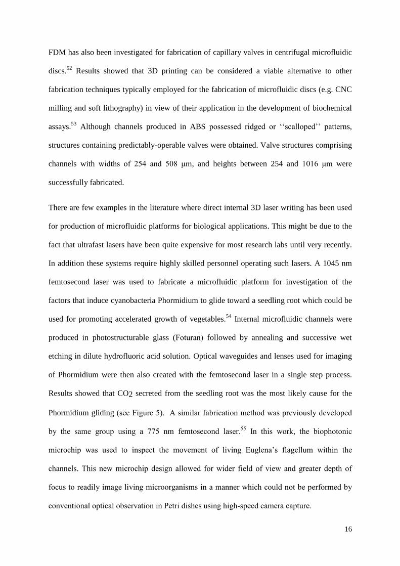
Results showed that CO2 secreted from the seedling root was the most likely cause for the
Phormidium gliding (see Figure 5). A similar fabrication method was previously developed
by the same group using a 775 nm femtosecond laser.55
In this work, the biophotonic
microchip was used to inspect the movement of living Euglena’s flagellum within the
channels. This new microchip design allowed for wider field of view and greater depth of
focus to readily image living microorganisms in a manner which could not be performed by
conventional optical observation in Petri dishes using high-speed camera capture.
17
FIG. 5. Investigation of the attractant inducing Phormidium gliding within the microfluidic channels.
Adapted with permission from Hanada et al., Lab Chip 11(12), 2109 (2011). Copyright 2011 Royal
Society of Chemistry
V. Concluding remarks
3D printing fabrication methods have to date not been widely utilised within the field of
microfluidics. This can be attributed to the poor resolution of cheap equipment, the
prohibitively high cost of high resolution equipment, and the lack of availability of suitable
materials from 3D printing technologies. However, the expiration of key 3D printing patents
in recent years has brought many 3D printing technologies to the consumer market, making
them more affordable and spurring competition between the newly formed companies
18
supplying into this area. The rapid increase in the capabilities and availability of these rapid
prototyping technologies, and at much reduced cost, has open the door to the exploration of
3D printing as an alternative to more conventional 2D microfabrication methods typically
employed in the fabrication of microfluidics platforms. Recent studies have actually shown
that 3D printing methods can effectively be used for producing micrometer scale internal
channels within bulk biocompatible and transparent materials for a cost as low as $2 per
chip,44
confirming the feasibility of this approach for rapid prototyping of cost-effective
microfluidic devices in a single step. Continuous improvements in resolution are expected,
even below the currently available TPP devices. However, it is clear that further research is
needed in two main areas: removal of support material from complex geometries and
development of new resins for SL.
Direct internal 3D laser writing of microchannels presents another promising option for fast
accurate production of complicated 3D microfluidic systems. Using a high frequency pulsed
femtosecond laser it is possible to create internal channels in a range of glass and polymer
materials. Internal optics and actuating elements can also be fabricated using such laser
writing techniques. However, the equipment complexity and operator’s skill level is still
relatively high for this fabrication route in comparison to 3D printing methods.
The benefit of these direct 3D fabrication technologies can be seen in the biological
applications for which they have already been used. Resin biocompatibility and optical
transparency as well as high accuracy of SL 3D printing have allowed fabrication of
microfluidics platforms for applications in cell culture and cell imaging. New microfluidic
designs integrating electrodes and membrane inserts were successfully employed in the

19
electrochemical detection of neurotransmitters and viruses, collection of biologically relevant
analytes (e.g. ATP), and drug transport studies. Direct internal 3D laser writing also
facilitated the production of suitable microfluidic-based photonic platforms for observation of
living organisms. Based on all the above, it is fair to expect that direct 3D fabrication
methods will play an important role in biomicrofluidics in the near future, with possible new
applications in POC diagnostics, cell culture, drug discovery, organs-on-chip, or even
forensic analysis, to name just a few.
Acknowledgments
Financial support from Science Foundation Ireland (Grant Numbers 12/IA/1576 &
12/RC/2289) and the Naughton Foundation (Naughton Graduate Fellowship) is gratefully
acknowledged.

20
References
1 P.N. Nge, C.I. Rogers, and A.T. Woolley, Chem. Rev. 113, 2550 (2013).
2 E. Verpoorte, Electrophoresis (2002), pp. 677–712.
3 J.F. Dishinger and R.T. Kennedy, Anal. Chem. 79, 947 (2007).
4 P.S. Dittrich and A. Manz, Nat. Rev. Drug Discov. 5, 210 (2006).
5 P. Liu and R. A. Mathies, Trends Biotechnol. 27, 572 (2009).
6 H. Kimura, T. Yamamoto, H. Sakai, Y. Sakai, and T. Fujii, Lab Chip 8, 741 (2008).
7 D. Huh, B.D. Matthews, A. Mammoto, M. Montoya-Zavala, H.Y. Hsin, and D.E. Ingber,
Science 328, 1662 (2010).
8 M. Tsai, A. Kita, J. Leach, R. Rounsevell, J.N. Huang, J. Moake, R.E. Ware, D.A. Fletcher,
and W.A. Lam, J. Clin. Invest. 122, 408 (2012).
9 D. Huh, G. A. Hamilton, and D.E. Ingber, Trends Cell Biol. 21, 745 (2011).
10 E.K. Sackmann, A.L. Fulton, and D.J. Beebe, Nature 507, 181 (2014).
11 G.M. Whitesides, Nature 442, 368 (2006).
12 H. Becker, Lab Chip 9, 1659 (2009).
13 H. Becker, Lab Chip 9, 2119 (2009).
14 B. Ziolkowski, M. Czugala, and D. Diamond, J. Intell. Mater. Syst. Struct. 24, 2221 (2012).
15 D. A. Collins, E.P. Nesterenko, D. Brabazon, and B. Paull, Anal. Chem. 84, 3465 (2012).
16 P. Tseng, C. Murray, D. Kim, and D. Di Carlo, Lab Chip 14, 1491 (2014).
17 A. Ben Azouz, M. Vázquez, and D. Brabazon, in Compr. Mater. Process., edited by S.
Hashmi, 1st Ed. (Elsevier Ltd, Oxford, UK, 2014), pp. 447–458.
18 D.C. Duffy, J.C. McDonald, O.J. Schueller, and G.M. Whitesides, Anal. Chem. 70, 4974
(1998).
19 A. Waldbaur, H. Rapp, K. Länge, and B.E. Rapp, Anal. Methods 3, 2681 (2011).
20 A.K. Au, W. Lee, and A. Folch, Lab Chip 14, 1294 (2014).
21 C.W. Hull, U.S. patent 4 575 330 (11 March 1986).

21
22 B.C. Gross, J.L. Erkal, S.Y. Lockwood, C. Chen, and D.M. Spence, Anal. Chem. 86, 3240
(2014).
23 See http://www.sciencedaily.com/releases/2009/04/090414084617.htm for "Custom-Fit,
Biocompatible Materials For Rapid Prototyping, Science Daily" (2009).
24 I.U. Ahad, A. Bartnik, H. Fiedorowicz, J. Kostecki, B. Korczyc, T. Ciach, and D.
Brabazon, J. Biomed. Mater. Res. Part A 102(9), 3298-3310 (2014).
25 A. Ostendorf and B.N. Chichkov, Photonics Spectra 40(10), 72-78 (2006).
26 T. Honegger, T. Elmberg, K. Berton, and D. Peyrade, Microelectron. Eng. 88, 2725 (2011).
27 S.S. Crump, U.S. patent 5 121 329 (9 June 1992).
28 S. Juodkazis, V. Mizeikis, and H. Misawa, J. Appl. Phys. 106, 051101 (2009).
29 Y. Bellouard, A. Champion, B. Lenssen, M. Matteucci, A. Schaap, M. Beresna, C. Corbari,
M. Gecevicius, P. Kazansky, O. Chappuis, M.Kral, R. Clavel, F. Barrot, J. M. Breguet, Y.
Mabilliard, S. Bottinelli, M. Hopper, C. Hoenninger, E. Mottay, and J. Lopez, J. Laser
Micro/Nanoeng 7, 1 (2012).
30 K.M. Davis, K. Miura, N. Sugimoto, and K. Hirao, Opt. Lett. 21, 1729 (1996).
31 A. Marcinkevicius, S. Juodkazis, V. Mizeikis, M. Watanabe, S. Matsuo, J. Nishii, and H.
Misawa, Proc. SPIE 4274, 469-477 (2001).
32 B. Fisette and M. Meunier, J. Laser Micro/Nanoeng. 1, 7 (2006).
33 L.N.D. Kallepalli, S. V. Rao, and N. R. Desai, Opt. Eng. 51, 073402 (2012).
34 M.E. Piyasena and S.W. Graves, Lab Chip 14, 1044 (2014).
35 I. Barbulovic-Nad, H. Yang, P.S. Park, and A.R. Wheeler, Lab Chip 8, 519 (2008).
36 S.J. Butler, D.W. Lee, C.W. Burney, J.C. Wigle, and T.Y. Choi, J. Biomed. Opt. 18,
117004 (2013).
37 G.T. Roman, Y. Chen, P. Viberg, A.H. Culbertson, and C.T. Culbertson, Anal. Bioanal.
Chem. 387, 9 (2007).
38 B. Harink, S. Le Gac, R. Truckenmüller, C. van Blitterswijk, and P. Habibovic, Lab Chip
13, 3512 (2013).
39 D. Choudhury, X. Mo, C. Iliescu, L.L. Tan, W.H. Tong, and H. Yu, Biomicrofluidics 5,
22203 (2011).
40 M. Sarris and A.G. Betz, Eur. J. Immunol. 39, 1188 (2009).
41 M.-H. Wu, S.-B. Huang, and G.-B. Lee, Lab Chip 10, 939 (2010).

22
42 M. Polonsky, I. Zaretsky, and N. Friedman, Brief. Funct. Genomics 12, 99 (2013).
43 T. Ozawa, K. Kinoshita, S. Kadowaki, K. Tajiri, S. Kondo, R. Honda, M. Ikemoto, L. Piao,
A. Morisato, K. Fukurotani, H. Kishi, and A. Muraguchi, Lab Chip 9, 158 (2009).
44 A.I. Shallan, P. Smejkal, M. Corban, R.M. Guijt, and M.C. Breadmore, Anal. Chem.
(2014).
45 D. Therriault, S.R. White, and J. A. Lewis, Nat. Mater. 2, 265 (2003).
46 W. Wu, A. DeConinck, and J. A. Lewis, Adv. Mater. 23, H178 (2011).
47 W. Lee, V. Lee, S. Polio, P. Keegan, J.-H. Lee, K. Fischer, J.-K. Park, and S.-S. Yoo,
Biotechnol. Bioeng. 105, 1178 (2010).
48 K.B. Anderson, S.Y. Lockwood, R.S. Martin, and D.M. Spence, Anal. Chem. 85, 5622
(2013).
49 M.E. Snowden, P.H. King, J. A. Covington, J. V Macpherson, and P.R. Unwin, Anal.
Chem. 82, 3124 (2010).
50 J.L. Erkal, A. Selimovic, B.C. Gross, S.Y. Lockwood, E.L. Walton, S. McNamara, R.S.
Martin, and D.M. Spence, Lab Chip 14, 2023 (2014).
51 L. Krejcova, L. Nejdl, M. A. M. Rodrigo, M. Zurek, M. Matousek, D. Hynek, O. Zitka, P.
Kopel, V. Adam, and R. Kizek, Biosens. Bioelectron. 54, 421 (2014).
52 J.L. Moore, A. McCuiston, I. Mittendorf, R. Ottway, and R.D. Johnson, Microfluid.
Nanofluidics 10, 877 (2011).
53 M. Vázquez, D. Brabazon, F. Shang, J.O. Omamogho, J.D. Glennon, and B. Paull, TrAC
Trends Anal. Chem. 30, 1575 (2011).
54 Y. Hanada, K. Sugioka, I. Shihira-Ishikawa, H. Kawano, A. Miyawaki, and K.
Midorikawa, Lab Chip 11, 2109 (2011).
55 K. Sugioka, Y. Hanada, and K. Midorikawa, Prog. Electromagn. Res. Lett. 1, 181 (2008).