Embed Size (px)
Citation preview
For further information:Nuclear Power Technology Development Section (NPTDS)Division of Nuclear PowerIAEA Department of Nuclear Energy
International Atomic Energy AgencyVienna International CentrePO Box 1001400 Vienna, Austria
Telephone: +43 1 2600-0Fax: +43 1 2600-7Email: Offi [email protected]: http://www.iaea.org
Printed by IAEA in AustriaAugust 2016
16-2
4301
Advances in Small Modular Reactor Technology Developments
A Supplement to:IAEA Advanced Reactors Information System (ARIS)2016 Edition
spine = 20.5 mm, 80gm paper
Advances in Small M
odular Reactor Technology Developm
ents
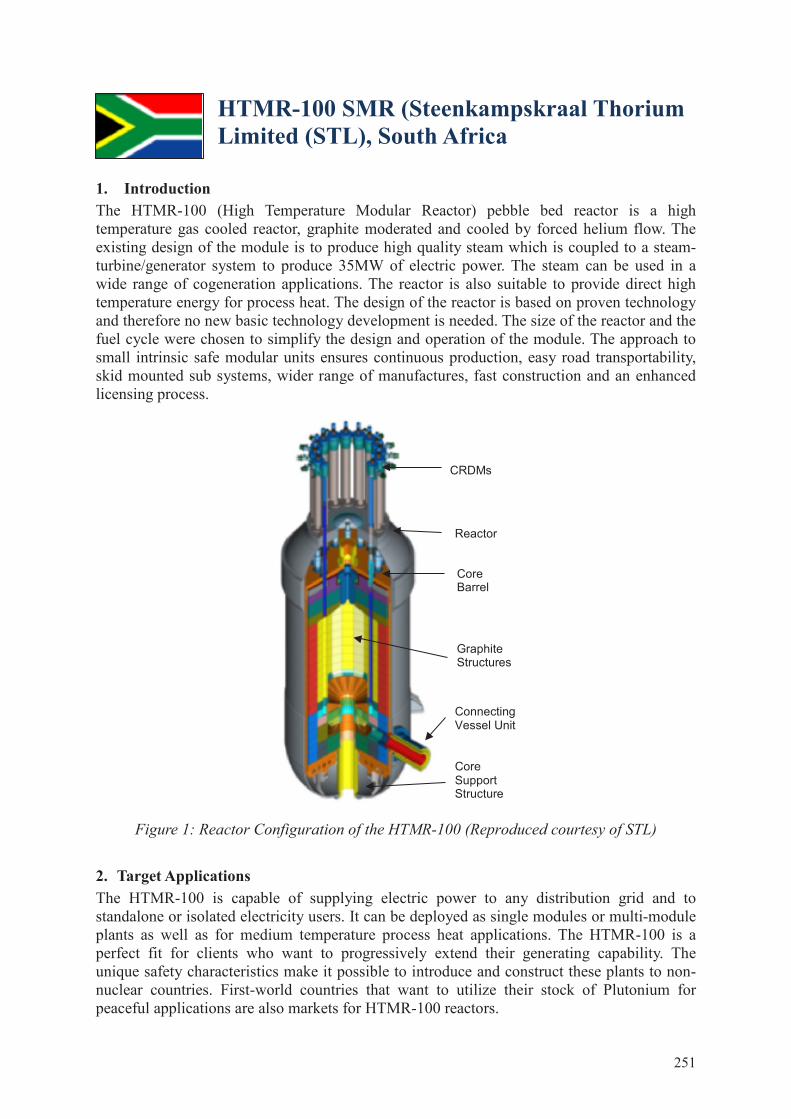
HTMR-100 SMR (Steenkampskraal Thorium Limited (STL), South Africa
1. Introduction The HTMR-100 (High Temperature Modular Reactor) pebble bed reactor is a high temperature gas cooled reactor, graphite moderated and cooled by forced helium flow. The existing design of the module is to produce high quality steam which is coupled to a steam-turbine/generator system to produce 35MW of electric power. The steam can be used in a wide range of cogeneration applications. The reactor is also suitable to provide direct high temperature energy for process heat. The design of the reactor is based on proven technology and therefore no new basic technology development is needed. The size of the reactor and the fuel cycle were chosen to simplify the design and operation of the module. The approach to small intrinsic safe modular units ensures continuous production, easy road transportability, skid mounted sub systems, wider range of manufactures, fast construction and an enhanced licensing process.
Figure 1: Reactor Configuration of the HTMR-100 (Reproduced courtesy of STL)
2. Target Applications The HTMR-100 is capable of supplying electric power to any distribution grid and to standalone or isolated electricity users. It can be deployed as single modules or multi-module plants as well as for medium temperature process heat applications. The HTMR-100 is a perfect fit for clients who want to progressively extend their generating capability. The unique safety characteristics make it possible to introduce and construct these plants to non-nuclear countries. First-world countries that want to utilize their stock of Plutonium for peaceful applications are also markets for HTMR-100 reactors.
Reactor
CRDMs
Core Barrel
Graphite Structures
Connecting Vessel Unit
Core Support Structure
251
3. Development Milestones 2012 Project started 2017 Preparation for Pre-license application 2018 Conceptual design finished
4. General Design Description
Design Philosophy The reactor has good load following characteristics which is needed for stand-alone (not grid coupled) applications. The “once through then out” (OTTO) fueling scheme leads to a simple and cost effective fuel management system. The relative low primary loop pressure requires a thinner walled pressure vessel and thus an easier manufacturing process, resulting in a wider range of vessel manufacturers. The HTMR-100 plant design caters for different site and client requirements. It allows flexibility in protection against external events and flexibility in multi module configuration and power capacity.
Reactor Core and Power Conversion Unit The reactor unit consists of a steel pressure vessel, a steel core barrel, graphite reflector blocks, neutron absorber rods, rod guide tubes, drive mechanisms and in-vessel instrumentation. The vessel is designed for 4 MPa pressure. The graphite structure allows for differential expansion and volumetric changes due to temperature and neutron fluence induced distortion. This is done to keep the stresses low and minimize primary fluid bypass and leaks. The side, top and bottom reflector material is nuclear grade graphite.
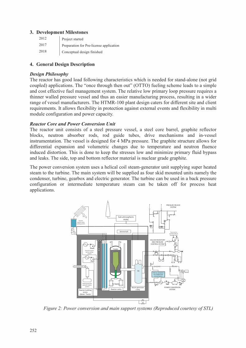
The power conversion system uses a helical coil steam-generator unit supplying super heated steam to the turbine. The main system will be supplied as four skid mounted units namely the condenser, turbine, gearbox and electric generator. The turbine can be used in a back pressure configuration or intermediate temperature steam can be taken off for process heat applications.
Figure 2: Power conversion and main support systems (Reproduced courtesy of STL)
HELIUM INVENTORY AND PRESSURE
CONTROL SYSTEM
Th100
P
Reactor cavity
Sub atmospheric HVAC
Service hall
Reactor building annex
(Water Tracts)
TO ATMOSPHERE
PACS
From and to purified helium storage tanks
PRESSURE RELIEVE SYSTEM
Secured reactor cavity cooling
system
Steam generator pressure relieve
system
Passive reactor cavity
cooling system
Steam generator cavity
Air
POWER CONVERSION SYSTEM
SG
To Spent
252
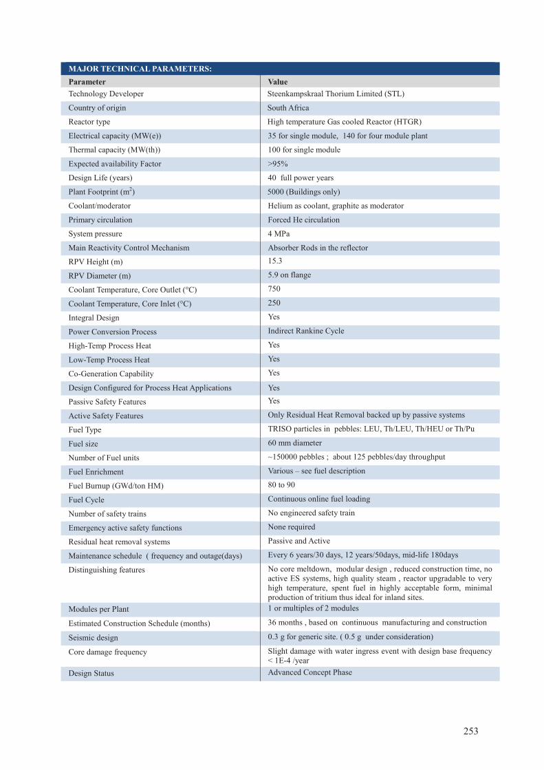
MAJOR TECHNICAL PARAMETERS:
Parameter Value Technology Developer Steenkampskraal Thorium Limited (STL)
Country of origin South Africa
Reactor type High temperature Gas cooled Reactor (HTGR)
Electrical capacity (MW(e)) 35 for single module, 140 for four module plant
Thermal capacity (MW(th)) 100 for single module
Expected availability Factor ˃95%
Design Life (years) 40 full power years
Plant Footprint (m2) 5000 (Buildings only)
Coolant/moderator Helium as coolant, graphite as moderator
Primary circulation Forced He circulation
System pressure 4 MPa
Main Reactivity Control Mechanism Absorber Rods in the reflector
RPV Height (m) 15.3
RPV Diameter (m) 5.9 on flange
Coolant Temperature, Core Outlet (°C) 750
Coolant Temperature, Core Inlet (°C) 250
Integral Design Yes
Power Conversion Process Indirect Rankine Cycle
High-Temp Process Heat Yes
Low-Temp Process Heat Yes
Co-Generation Capability Yes
Design Configured for Process Heat Applications Yes
Passive Safety Features Yes
Active Safety Features Only Residual Heat Removal backed up by passive systems
Fuel Type TRISO particles in pebbles: LEU, Th/LEU, Th/HEU or Th/Pu
Fuel size 60 mm diameter
Number of Fuel units ~150000 pebbles ; about 125 pebbles/day throughput
Fuel Enrichment Various – see fuel description
Fuel Burnup (GWd/ton HM) 80 to 90
Fuel Cycle Continuous online fuel loading
Number of safety trains No engineered safety train
Emergency active safety functions None required
Residual heat removal systems Passive and Active
Maintenance schedule ( frequency and outage(days) Every 6 years/30 days, 12 years/50days, mid-life 180days
Distinguishing features No core meltdown, modular design , reduced construction time, no active ES systems, high quality steam , reactor upgradable to very high temperature, spent fuel in highly acceptable form, minimal production of tritium thus ideal for inland sites.
Modules per Plant 1 or multiples of 2 modules
Estimated Construction Schedule (months) 36 months , based on continuous manufacturing and construction
Seismic design 0.3 g for generic site. ( 0.5 g under consideration)
Core damage frequency Slight damage with water ingress event with design base frequency < 1E-4 /year
Design Status Advanced Concept Phase
253
Fuel characteristics and Supply The fuel elements (FE) for the HTMR-100 are 60 mm diameter spheres consisting of a spherical fuel zone of approximately 50 mm diameter, in which the TRISO-coated particles are randomly distributed in the graphitic matrix material. A fuel-free shell of graphite matrix of about 5 mm in thickness is then moulded to the fuel zone. The fuel kernel and coatings serve as a fission product barrier in normal and accident operating conditions.
There are various types of fuel that will be used in the HTMR-100 reactor, ranging from LEU UO2 to mixtures of Th/LEU, Th/HEU and Th/Pu. The following options have already been studied and show to be viable:
i. LEU : <10% Enrichment, (7-10g HM/sphere) ii. Th/LEU: various options
a. 50% LEU by mass 20% enrichment, 50% Th (10-12g HM/sphere) b. 25% LEU by mass 20% enrichment, 75% Th (16-20g HM/sphere)
iii. Th/HEU, 10% HEU by mass 93% enrichment, 90% Th by mass (10-12g HM/sphere) iv. Th/Pu: 15% reactor grade Pu by mass, (12g HM/sphere)
A Fuel Qualification and Test programme will be conducted on the fuel prior to loading of the reactor. The HTMR-100 operates on a much longer burn-up fuel cycle compared to conventional reactors. The non-proliferation characteristic of the OTTO cycle is the extended time the pebbles reside inside the core, making it more difficult to divert partially burnt fuel.
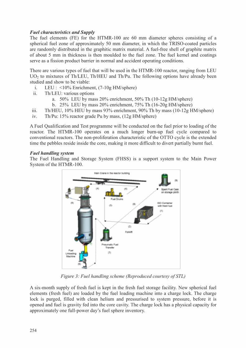
Fuel handling system The Fuel Handling and Storage System (FHSS) is a support system to the Main Power System of the HTMR-100.
Figure 3: Fuel handling scheme (Reproduced courtesy of STL) A six-month supply of fresh fuel is kept in the fresh fuel storage facility. New spherical fuel elements (fresh fuel) are loaded by the fuel loading machine into a charge lock. The charge lock is purged, filled with clean helium and pressurised to system pressure, before it is opened and fuel is gravity fed into the core cavity. The charge lock has a physical capacity for approximately one full-power day’s fuel sphere inventory.
254
Spent fuel is removed from reactor pressure vessel by means of two fuel unloading machines (FUMs), connected to a single reactor defueling chute. Each FUM discharges spent fuel into a discharge lock. The discharge locks have sufficient capacity for a full power day of spent fuel elements.
Spent fuel, damaged in such a manner that gravity conveyance is compromised, is mechanically separated inside the FUM and accumulated in a dedicated scrap canister, located inside the FUM.
Provision is made in the design of the FHSS for the temporary fitment of activity measuring devices. These are to be used for the removal of the first core graphite spheres. Separate burn-up measuring devices can also be temporarily installed for core performance and calculational purposes when running fuel composition trials.
During decommissioning the FHSS extracts the last used fuel in the same manner as during normal operation. Reactivity Control Eighteen neutron absorber rods are provided in graphite sleeves inside the graphite side reflector blocks. The absorber rods can be operated independently as a group or as sub-groups, as required by the reactor operating control system. A control rod consists of several rod absorber material segments, pinned together to form articulating joints. The segments consist of sintered B4C absorber material, sandwiched between an inner and an outer tube segment. The inner tube segment allows cooling helium gas to flow form the top down in the circular channels. Each rod is equipped with a position indicator which measures the position of the rod over its entire positioning range and with position indicators for the upper and lower limit positions.
Reactor Pressure Vessel and Internals The Reactor Pressure Vessel (RPV) is constructed to the ASME III subsection NB code. It comprises of two main components:
• reactor vessel body • vessel head which is bolted to the vessel body
The reactor vessel body consists of several forged ring-components circumferentially welded together.
The core structures consist of the metallic parts and the graphite structures. The function of these internal structures is to provide stable core geometry, neutron reflection, cold and hot gas channelling, fuel element flow, shielding, thermal insulation and support of the control and shutdown systems guide tubes and the neutron source. The functional design of the structural core internals is such that they are capable of withstanding the steady state and transient loadings during normal operation, anticipated operational occurrences and design basis accidents.
The shape and structure of the inner side reflector wall and the 30 ° angled core bottom permit uniform fuel element flow.
The loads borne by the ceramic internals are transferred to the steel core barrel and then to the reactor pressure vessel through metallic components such as the lower support structure and the core barrel axial and radial supports.
255
All areas of the core internals are designed for the service life of the reactor. Access for ceramic structure inspections can be done through the fuel loading channel and the reflector rod holes. 5. Plant Safety Features
Engineered Safety System Configuration and Approach In principle the plant is designed to perform its safety functions without reliance on the automated plant control system, or the operator. The engineered safety system of the plant has no engineered safety systems in terms of active human or machine intervention to assure nuclear safety. The low power density, the large mass of the core structures, the slender core geometry and the use of materials capable of withstanding high temperatures ensure complete passive residual heat removal capability without exceeding design limits of components. Provision for beyond design basis conditions is made. Beyond design basis scenarios include the non-functioning/non-insertion of all active control and shutdown systems. The reactor core characteristics e.g. small excess reactivity and strong negative reactivity coefficient with temperature will shut down the reactor and maintain a condition where no damage to the fuel, core structures and reactor vessel occurs. Excessive reactivity increase during water or water vapor ingress (increasing moderation) is prevented by designing the reactor for limited heavy metal content of the fuel.
Reactor Cooling Philosophy The Reactor Cavity Cooling System (RCCS) removes heat radiated from the reactor towards the reactor cavity walls. It consists of welded membrane tubes arranged side-by-side on the inside of in the reactor cavity wall. Water is circulated through the tubes to form a cold wall. The RCCS is a passive system and consists of three independent cooling trains and is designed for all postulated design basis conditions. Containment Function The primary fission product barrier is the TRISO coated fuel particles, which keep the fission products contained under all postulated events, even if the second barrier (the primary pressure vessel system) and the third barrier (the building filter system) collapse. 6. Plant Safety and Operational Performances The central consideration is the demand for high availability of process steam supply and/or electricity generation. To reduce or minimize the NSSS daily or weekly load changes of the reactor, the preference is to change the ratio between steam supply and electricity supply. Excess steam and/or electricity can be utilized in the desalination plants to provide water as a sellable commodity earning additional revenue. This allows the plant to operate virtually continually at full power very close to the plant availability. In order to maintain the plant safety and operational performance, specific areas are controlled for human occupation and protection.
7. Instrumentation and Control Systems The Automation System (ATS) comprises that group of safety and non-safety I&C systems that provide automated protection, control, monitoring and human-system interfaces. The following three specific systems in the HTMR-100 system structure define control and instrumentation:
• Plant control, data and instrumentation system: Provides overall plant control and monitoring. It includes architecture which combines I&C systems and the control
256
room equipment. • Equipment/Investment Protection System: Reduce the risk of losing critical or
expensive components by maintaining the plant within its normal and safe operating envelope.
• Protection System: Initiates reactor SCRAM to protect against nuclear control failure or loss of primary coolant, etc.
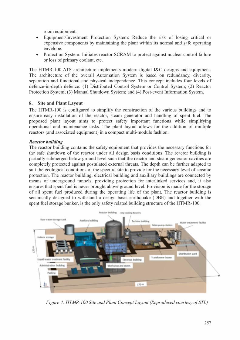
The HTMR-100 ATS architecture implements modern digital I&C designs and equipment. The architecture of the overall Automation System is based on redundancy, diversity, separation and functional and physical independence. This concept includes four levels of defence-in-depth defence: (1) Distributed Control System or Control System; (2) Reactor Protection System; (3) Manual Shutdown System; and (4) Post-event Information System. 8. Site and Plant Layout The HTMR-100 is configured to simplify the construction of the various buildings and to ensure easy installation of the reactor, steam generator and handling of spent fuel. The proposed plant layout aims to protect safety important functions while simplifying operational and maintenance tasks. The plant layout allows for the addition of multiple reactors (and associated equipment) in a compact multi-module fashion.
Reactor building The reactor building contains the safety equipment that provides the necessary functions for the safe shutdown of the reactor under all design basis conditions. The reactor building is partially submerged below ground level such that the reactor and steam generator cavities are completely protected against postulated external threats. The depth can be further adapted to suit the geological conditions of the specific site to provide for the necessary level of seismic protection. The reactor building, electrical building and auxiliary buildings are connected by means of underground tunnels, providing protection for interlinked services and, it also ensures that spent fuel is never brought above ground level. Provision is made for the storage of all spent fuel produced during the operating life of the plant. The reactor building is seismically designed to withstand a design basis earthquake (DBE) and together with the spent fuel storage bunker, is the only safety related building structure of the HTMR-100.
Figure 4: HTMR-100 Site and Plant Concept Layout (Reproduced courtesy of STL)
257
Electrical building The EB houses the main control and computer rooms, primary and secondary plant security alarms rooms and provides the primary access facilities for the nuclear island and the energy conversion area. This centre also provides space for activities associated with plant administration and security services. The plant control, data, and instrumentation system control/display panels and computers are housed in the control room.
Turbine Generator Building The Turbine Building provides the foundation and housing for the Power Conversion System, including other support systems such as the compressed air, water sampling, HVAC, Voltage Distribution Systems, permanent 11kVAC and 400VAC diesel generator sets and steam safety valves.
Balance of Plant The balance of plant consists of the secondary systems and the tertiary systems. The Power Conversion System (PCS) has one set of isolation valves between itself and the Nuclear Steam Supply System (NSSS). The PCS and its major subsystems are of non-nuclear safety class thus conventional safety class and the product is of high quality industrial standard.
Electric Power Systems The Electrical Power Supply System (EPSS) for the single module HTMR-100 plant supplies power to the plant safety and non-safety equipment for normal plant operation, start-up, normal shutdown as well as for accident mitigation and safe shutdown. The EPSS provides the following voltage levels: 230VAC, 400VAC, 11kVAC, 24/48VDC and 250VDC. The primary voltage of the Station Feeder Transformer is transmission grid dependent and thus site specific. The majority of plant loads are powered from the Main Power Supply System (MPSS) while all safety-related loads as well as non-safety related loads on the Nuclear Island (NI) portion of the EPSS are powered by the Reactor Power Supply System (RPSS). The Reactor Protection System (RPS) and some non-safety related loads (i.e. Primary Blowers 1 & 2, etc.) are powered from the RPSS. A portion of the RPSS circuit (inside the reactor building) is categorized as safety-related (Class1E).
9. Design and Licensing Status Conceptual design is in an advanced stage. The core nucleonic, thermo-hydraulic and heat transfer analyses are being done to optimize the performance and verify the safety analysis. Nuclear Regulator engagement is planned for 2017 with the aim of commencing the pre-assessment for licensing in order to reach design certification status at the end of the Concept Phase. 10. Plant Economics Since the HTMR-100 is mainly intended to service the needs of isolated geographical areas, it is not meant to compete economically with large (>1GW) reactors connected to an existing national grid. The HTR SMR comes into its own right when the various combinations of electricity, process heat and water desalination are considered and holds great promise for the long term economics of users. Preliminary capital and operating cost studies indicate that this flexibility of the HTMR-100 provides the most efficient energy to isolated communities and industries. It is well suited to deployment in developing countries with its affordability and Gen IV safety characteristics.
258
For further information:Nuclear Power Technology Development Section (NPTDS)Division of Nuclear PowerIAEA Department of Nuclear Energy
International Atomic Energy AgencyVienna International CentrePO Box 1001400 Vienna, Austria
Telephone: +43 1 2600-0Fax: +43 1 2600-7Email: Offi [email protected]: http://www.iaea.org
Printed by IAEA in AustriaAugust 2016
16-2
4301
Advances in Small Modular Reactor Technology Developments
A Supplement to:IAEA Advanced Reactors Information System (ARIS)2016 Edition
spine = 20.5 mm, 80gm paperAdvances in Sm
all Modular Reactor Technology D
evelopments