Embed Size (px)
Citation preview
so TRANSPORTATION RESEARCH RECORD 1314
Advanced Train Control Systems Control Flow Development and Validation
ROBERT G. AYERS
The Railway Association of Canada and the Association of American Railroads initiated the Advanced Train Control Systems (AT~) project in 1984. The railroads developed an operating r~qmrements document and contracted a team of engineering firms (ARINC Research Corporation , Transportation and Distribution Associate , and Lapp-Hancock, Ltd.) to act as the system engineering team. The project then published a technology ~ssessm~nt, a number of draft specifications that defined a physical architecture , and a preliminary high-level assignment of functional requirements to physical components. It soon became clear that a method was required to document how the various components of ATCS hould cooperate in carrying out railroad operations. In 1987, the first version of this documentation , known as Control Flows, was produced using the MacDraw software package and consisted of a set of high-level figures depicting the application logic. Since that time, rai lroad industry reviews have rapidly increased the detailed information contained in each flow. The project quickly outgrew the capabilities of the MacDraw tool as well as the flow chart format (Easy-Flow) and computer-aided software engineering tool (STATEMATE) that were subsequently adopted. The project abandoned ST ATEMATE in favor of ADA Syntax Program Design Language, which is readily convertible to software. Logic specifications written in ADA have been published and are designed to significantly reduce ambiguity , enhance maintainability, and provide a solid basis for future deve_lopment by both the ATCS project and the supplier commumty.
The Advanced Train Control Systems (ATCS) project was initiated by the Railway Association of Canada (RAC) and the Association of American Railroads (AAR) in 1984. The purpose of the project was to develop a series of comprehensive and advanced operating systems for the control of train movement that are considered to be essential for improving safety, productivity, and energy efficiency of railroads . This paper describes the process by which the system logic was developed starting from operating concepts and proceeding to detailed software specifications.
OPERATING REQUIREMENTS
The project's first major endeavor was to develop a document entitled, " Advanced Train Control Systems Operating Requirements." This document enumerated the economic, operating, and safety objectives for ATCS and a set of operating requirements.
ARINC Research Corporation, MS S-371, 2551 Riva Road, Annapolis, Md. 21401.
The operating requirements section of the document was structured as a hierarchical set of lists. At the lowest level of the hierarchy were short narrative descriptions of individual requirements. The top level of the hierarchy consisted of six items:
1. Presence detection, train identification, and location, 2. Track and route integrity, 3. Ancillary systems interface, 4. Switch control, 5. Train control , and 6. Management of train operations.
The operating requirements document did not detail techniques to be used to accomplish the requirements, the components of ATCS , or the interfaces among components.
The ATCS project , having established its requirements, engaged a team led by ARINC Research Corporation to act as the systems engineer on the project.
TECHNOLOGY ASSESSMENT
The first step in the process of developing a system architecture was to perform a technology assessment. This study looked at a number of technologies that might benefit ATCS, but concentrated on technologies supporting three major areas: vehicle locations systems, data communications systems, and display systems.
Having determined the likely technologies to be used in ATCS, the project set out to develop a system architecture and form, fit, function (F3) specifications for the ATCS components. To facilitate this process , committees were established that included representatives from the railroads, system engineers, manufacturers, and system integrators. Participants from all groups provided input to the specifications; however, when a committee failed to reach a consensus on any issue, the railroad representatives voted to determine how the specifications would be developed.
The committee process led to rapid advances in developing a system architecture, hardware specifications, and data communications specifications for ATCS. It became clear by 1987 that a method was required to document how the various components of A TCS should cooperate in carrying out railroad operations. This led to the development of the first generation of Control Flows, which later became known as the
Ayers
"Macintosh Flows" because they were developed on a Macintosh computer using the MacDraw package .
MACINTOSH FLOWS
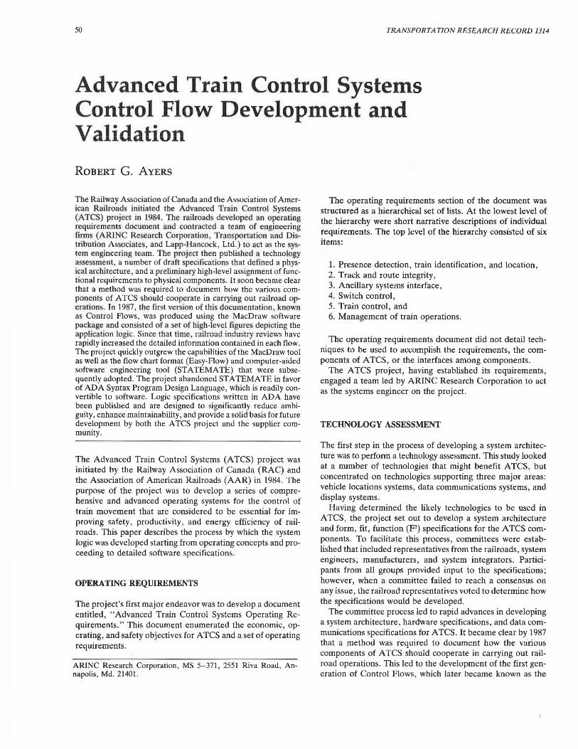
The Macintosh Flows described each of a number of railroad operations in a two-page format (Figures 1 and 2). One page showed the flow of control (at a very high level) and the other showed data flows among components. These flows were reviewed by railroad operations and signal representatives and updated to reflect their inputs.
The Macintosh Flows were quite useful in validating the initial assignment of functionality to components and the highlevel view of how ATCS should work with the railroad community. They had serious shortcomings as design documentation, however, because their high-level view abstracted out important decision-making processes within components, such as how the central dispatch computer determined if an authority request was safe to issue.
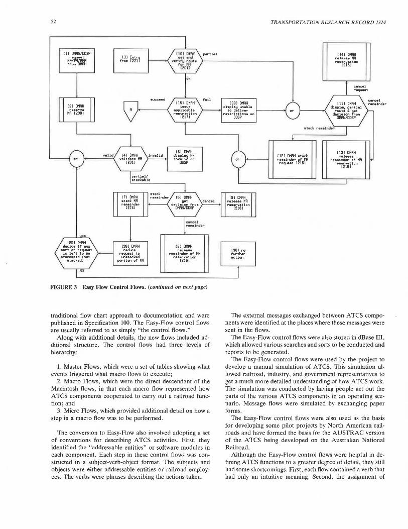
EASY-FLOW CONTROL FLOWS
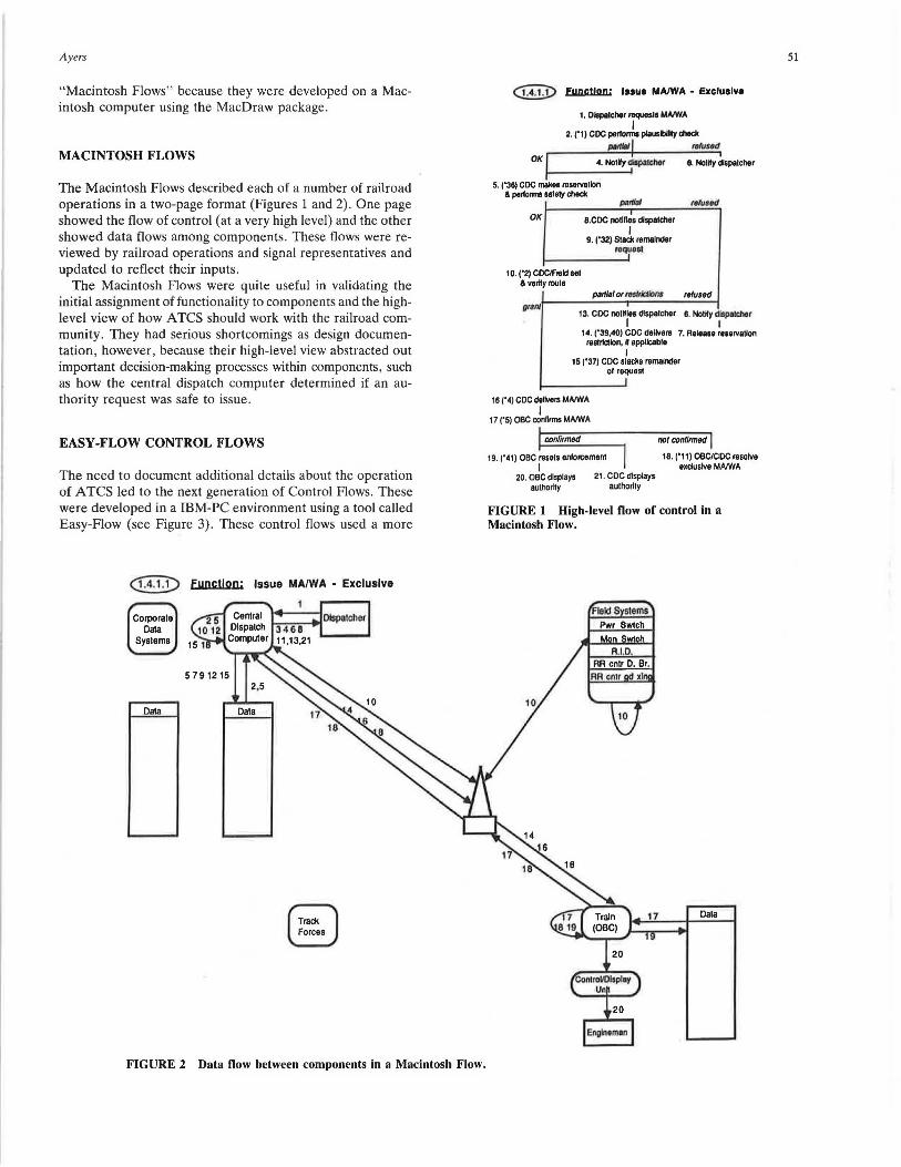
The need to document additional details about the operation of A TCS led to the next generation of Control Flows. These were developed in a IBM-PC environment using a tool called Easy-Flow (see Figure 3). These control flows used a more
@II) Fync!loo: Issue MA/WA - Exclusive
Corporals Data
Syslems
Oala
FIGURE 2 Data flow between components in a Macintosh Flow.
<1I!J) Function; IHue MA/WA - Exclusive
1. Diepllcher requeals MNWA I
2. ('1) CDC perlOnnS plausYy died<
""'*"! rohnff OK 1-l----4._No_1_Ny....,~lchet 8. NolKy ~lspalcher
5. ('36) CDC makes reservallon & pe~orms aaloly chack
OK
10. ('2) CDC/Field sol & verify roule
a.CDC nollllea dlspalcher I
9. ('32) Slack remainder roque81
tfhJltd
part/al or toslrlctlonJ rel used
13. CDC nolKles dlspalcher 8. Nollly dispalChet I I
14. ('39,40) CDC dellvers 7. Release reservallon reS1rk:Uon, K applicable
I 15 ('37) CDC slacks remainder
ol requesl
16 ('4) CDC dellvers MNWA I
17 ('5) OBC conllmls MNWA
I
confirmed not confirmed
19. ('41) OBC resels enlorcemenl 18. ('11) OBCICDC resolve I excluslve MANIA
20. OBC displays 21 . CDC displays aulhor"y aulhorlly
FIGURE 1 High-level flow of control in a Macintosh Flow.
Dal a
Englneman
51
52
I I I DHAN/DOSP
PA'fA'~~A ream OHAH
121 OHAH reaerve
HA 12091
r~~! r~m
invalid
part1al/ stackable
stack re1t1ainder
1101 OI AY p•rtial • •• •nd
ver"~=~ ~oule 12071
ok
foll I 151 DHAH
issue applicable re&1r1ct1on
12171
171 OHAH etock HA re1r1atnder
get cancel !+---- -< dec ision f'rorn ,__ _ _ 12151
1291 OHAH reduce
r•quaat to 1Jnetecked
portion of HA
OHAN/DOSP
CBI DMAH release
remainder of' MA reservation
12161
FIGURE 3 Easy Flow Control Flows. (continued on next page)
traditional flow chart approach to documentation and were published in Specification 100. The Easy-Flow control flows are usually referred to as simply "the control flows."
Along with additional details , the new flows included additional structure. The control flows had three levels of hierarchy:
1. Master Flows, which were a set of tables showing what events triggered what macro flows to execute;
2. Macro Flows , which were the direct descendant of the Macintosh flows, in that each macro flow represented how ATCS components cooperated to carry out a railroad function; and
3. Micro Flows, which provided additional detail on how a step in a macro flow was to be performed.
The conversion to Easy-Flow also involved adopting a set of conventions for describing ATCS activities . First , they identified the "addressahle entities" or software modules in each component. Each step in these control flows was constructed in a subject-verb-object format. The subjects and objects were either addressable entities or railroad employees. The verbs were phrases describing the actions taken .
1391 OHAH dieplay unable
to deliver reatrJct1on& on
OOSP
191 OMAH releaae MA raaervat ion
12161
1301 no further action
TRANSPORTATION RESEARCH RECORD 1314
1121 OHAH otock remainder of' HA coquaat 12151
I 141 DHAH rel•••• 11A re•arvation
12161
cancel raqu.at
I 131 DHAH raleaea
remainder of' MA reservation
12161
The external messages exchanged between A TCS components were identified at the places where these messages were sent in the flows.
The Easy-Flow control flows were also stored in dBase III , which allowed various searches and sorts to be conducted and reports to be generated .
The Easy-Flow control flows were used by the project to develop a manual simulation of ATCS. This simulation allowed railroad, industry , and government representatives to get a much more detailed understanding of how ATCS work . The simulation was conducted by having people act out the parts of the various A TCS components in an operating scenario. Message flows were simulated by exchanging paper forms.
The Easy-Flow control flows were also used as the basis for developing some pilot projects by North American railroads and have formed the basis for the AUSTRAC version of the ATCS being developed on the Australian National Railroad.
Although the Easy-Flow control flows were helpful in defining ATCS functions to a greater degree of detail, they still had some shortcomings. First, each flow contained a verb that had only an intuitive meaning. Second, the assignment of
Ayers
11••
deter1Une if no ,,,,_~ conflict •><i•t
with thia reaerv•tton
1321 OHAH reeerve
euthor1tbl for train• location
12091
1201 LAUT reset
enforcement 11231
1341 OHRH diapley/ennunci•t• conflict on OOSP
Of
1191 LTRH calculate
enforca111ent curve 11101
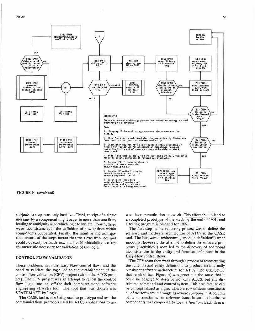
FIGURE 3 (continued)
r---0
1231 No A further -action
1261 Ot1AH 1361 LLOC 1161 OHAH 1181 OHAH note HA 1aaue note receipt
deliver HA to ~A·~~·~osf:w i---- 1n hietoricel of' querw for LAUT log ICF 1·4·2·11
•top 26
1211 1351 DllAH 1371 lHlH 1171 LAUT invalid LAUT/OHAH decJ.de if new ., .. •end locet ion
volldota HA resolve HA li • H• end at oLB~no'eCac I 101 I conf'l ict dupetch I 1071 boundor11
valid no
dectde 1• no
OBJECTIVE:
1221 OHAH·1-'------M train flagged ...
To ieeue proeead 11uthorit1:11 proceed restricted authority, or work euthorit1:1 to a 1t1ove1r1ent .
Note:
1 · "Oispla~ HA Invalid" always contains the reason f'or the display·
2 · Thia function 18 only u&ed when the nei..i authority limit& ere leas restrictive than the previous authoritw·
3 · Dispatcher m11y not have all of options shown dep•nd1ng on
~~:~~~ i ~~r 1 r:~ ::·!~~no~·~!~~~!::~~:!~: n~! ·~=t~~i~ ~:q~::~k remainder)·
~A ~~·~07.~~~r:t:~t~~r~~~l~f t~ef~::~n~~~ =~~ce:b~!~lly validated
~ioI~t:t:~. 2~8~f 1 1~~!~. :l~h:bout to answer should be no•
S • In step 32 authority to be :lauued :la work authority for train'& reported limits .
7 • In step 34 there 1s a po&eible lap of outstanding authorities and with current loc1111on thie ia being announced ·
I 271 OHAH note train flagged not a •rogue" in historical
log
"'rogue'"
.,..
m1 llllAtl no decide 1•
tr•1n uuh1n ntw lJ.l:lt•
~ ..
1251 OHAH flag train ea not 11 "rogue"
53
subjects to steps was only intuitive. Third, receipt of a single message by a component might occur in more than one flow, leading to ambiguity as to which logic to initiate. Fourth, there were inconsistencies in the definition of how entities within components cooperated. Finally, the intuitive and nonrigorous nature of the steps meant that the flows were not and could not easily be made machinable. Machinability is a key characteristic necessary for validation of the logic.
cess the communications network. This effort should lead to a completed prototype of the stack by the end-of 199(and a testing program is planned for 1992.
The first step in the rehosting process was to define the software and hardware architecture of ATCS to the CASE tool. The hardware architecture ("module definition") went smoothly; however, the attempt to define the software processes ("activities") soon led to the discovery of additional inconsistencies in the entity and function definitions in the Easy-Flow control flows. CONTROL FLOW VALIDA TOR
These problems with the Easy-Flow control flows and the need to validate the logic led to the establishment of the control flow validation (CFV) project (within the ATCS project). The CFV project was an attempt to rehost the control flow logic into an off-the-shelf computer-aided software engineering (CASE) tool. The tool that was chosen was STATEMATE by Logix.
The CASE tool is also being used to prototype and test the communications protocols used by ATCS applications to ac-
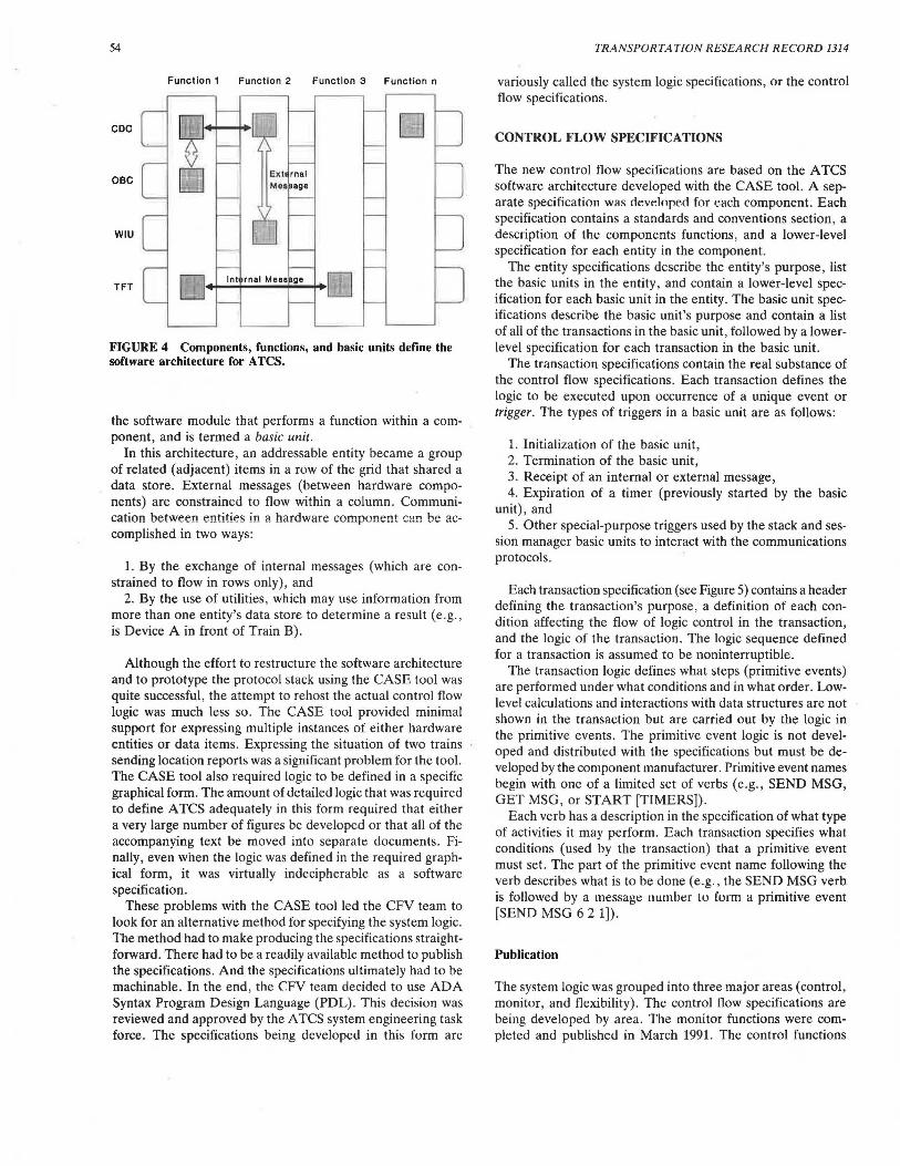
The CFV team then went through a process of restructuring the function and entity definitions to produce an internally consistent software architecture for ATCS. The architecture that resulted (see Figure 4) was generic in the sense that it could be adapted to describe not only ATCS, but any distributed command and control system. This architecture can be conceptualized as a grid where a row of items constitutes all of the software in a single hardware component. A column of items constitutes the software items in various hardware components that cooperate to form a function. Each item is
54
Function 1 Function 2 Function 3 Function n
CDC []
OBC
WIU
TFT
FIGURE 4 Components, functions, and basic units define the software architecture for ATCS.
the software module that performs a function within a component, and is termed a basic unit.
In this architecture , an addressable entity became a group of related (adjacent) items in a row of the grid that shared a data store. External messages (between hardware components) are constrained to flow within a column. Communication between entities in a hardware component can be accomplished in two ways:
1. By the exchange of internal messages (which are constrained to flow in rows only), and
2. By the use of utilities , which may use information from more than one entity's data store to determine a result (e.g. , is Device A in front of Train B).
Although the effort to restructure the software architecture and to prototype the protocol stack using the CASE tool was quite successful, the attempt to rehost the actual control flow logic was much less so. The CASE tool provided minimal support for expressing multiple instances of either hardware entities or data items. Expressing the situation of two trains sending location reports was a significant problem for the tool. The CASE tool also required logic to be defined in a specific graphical form. The amount of detailed logic that was required to define ATCS adequately in this form required that either a very large number of figures be developed or that all of the accompanying text be moved into separate documents. Finally, even when the logic was defined in the required graphical form, it was virtually indecipherable as a software specification.
These problems with the CASE tool led the CFV team to look for an alternative method for specifying the system logic. The method had to make producing the specifications straightforward. There had to be a readily available method to publish the specifications. And the specifications ultimately had to be machinable. In the end, the CFV team decided to use ADA Syntax Program Design Language (PDL). This decision was reviewed and approved by the A TCS system engineering task force . The specifications being developed in this form are
TRANSPORTATION RESEARCH RECORD 1314
variously called the system logic specifications, or the control flow specifications.
CONTROL FLOW SPECIFICATIONS
The new control flow specifications are based on the ATCS software architecture developed with the CASE tool. A separate specification was cieveloped for each component. Each specification contains a standards and conventions section, a description of the components functions, and a lower-level specification for each entity in the component.
The entity specifications describe the entity's purpose, list the basic units in the entity, and contain a lower-level specification for each basic unit in the entity. The basic unit specifications describe the basic unit's purpose and contain a list of all of the transactions in the basic unit, followed by a lowerlevel specification for each transaction in the basic unit .
The transaction specifications contain the real substance of the control flow specifications. Each transaction defines the logic to be executed upon occurrence of a unique event or trigger. The types of triggers in a basic unit are as follows:
1. Initialization of the basic unit, 2. Termination of the basic unit, 3. Receipt of an internal or external message, 4. Expiration of a timer (previously started by the basic
unit), and 5. Other special-purpose triggers used by the stack and ses
sion manager basic units to interact with the communications protocols.
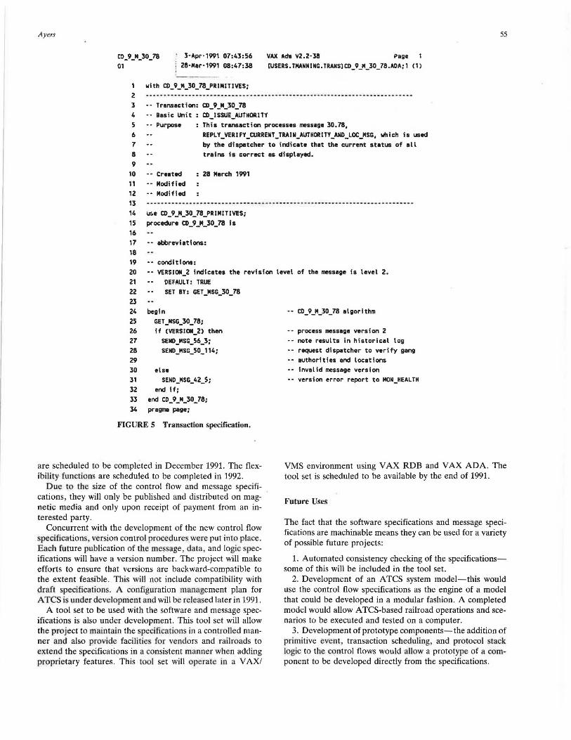
Each transaction specification (see Figure 5) contains a header defining the transaction's purpose, a definition of each condition affecting the flow of logic control in the transaction , and the logic of the transaction . The logic sequence defined for a transaction is assumed to be noninterruptible.
The transaction logic defines what steps (primitive events) are performed under what conditions and in what order . Lowlevel calculations and interactions with data structures are not shown in the transaction but are carried out by the logic in the primitive events. The primitive event logic is not developed and distributed with the specifications but must be developed by the component manufacturer. Primitive event names begin with one of a limited set of verbs (e .g., SEND MSG, GET MSG, or START (TIMERS]) .
Each verb has a description in the specification of what type of activities it may perform. Each transaction specifies what conditions (used by the transaction) that a primitive event must set. The part of the primitive event name following the verb describes what is to be done (e.g., the SEND MSG verb is followed by a message numbt:r Lu form a primitive event (SEND MSG 6 2 1]).
Publication
The system logic was grouped into three major areas (control , monitor, and flexibility) . The control flow specifications are being developed by area. The monitor functions were completed and published in March 1991. The control functions
A yers
co_9_M_30_78 01
3·Apr·1991 07:43:56 28-Mer-1991 08:47:38
1 with co_9_M_30_78_PRIMITIVES;
55
VAX Ade V2.2·38 Page [USERS.TMANNING.TRANS]C0_9_M_30_78.AOA;1 (1)
2 ··--- - ------------------------------- - ------------····· - - - -- - -------···-··· 3 •· Transaction: CD_9_M_30_78 4 ·· Basic Unit CD_ISSUE_AUTHORITY 5 •• Purpose 6 7 8
This transaction processas message 30.78, REPLY_VERIFY_ctJRRENT_TRAIN_AUTHORITY_AND_LOC_MSG, which is used by the dispatcher to indicate th1t the current status of ell tr1ins is correct 1s displayed.
9
10 · - Created 11 ·· Modified 12 -· Modified
28 March 1991
13 ····---·-·· · ---··-··-·····--····-·-····-········- ---·- ······ · · ··· ·--·· · ···· 14 ui.e CD_9_M_30_78_PRIMITIVES; 15 procedure CD_9_M_30_78 is 16 17 -· ebbreviations: 18 19 ·- conditions: 20 -- VERSI011_2 Indicates the revision level of the message is level 2. 21 DEFAULT: TRUE 22 SET BY: GET_MSG_30_78 23 24 begin 25 GET_MSG_30_78; 26 if (VERSI011_2) then 27 SEND_MSG_56_3; 28 SENl>_MSG_50_114; 29
30 else 31 SEND_MSG_42_5; 32 end if; 33 end co_9_M_30_78; 34 pr agma page;
FIGURES Transaction specification.
are scheduled to be completed in December 1991. The flexibility fu.nctions are scheduled to be completed in 1992.
Due to the size of the control flow and message specifications, they will only be published and distributed on magnetic media and only upon receipt of payment from an interested party.
Concurrent with the development of the new control flow specifications, version control procedures were put into place. Each future publication of the me sage, data and logic specifications will have a version number. The project will make efforts to ensure that versions are backward-compatible to the extent feasible. This will not include compatibility with draft specifications. A configuration management plan for ATCS is underdevelopment and will be relea ed later in 1991.
A tool set to be used with the software and message specifications is also under development. This tool set will allow the project to maintain the specification in a controlled manner and also provide facilities for vendors and railroads to extend the specifications in a consistent manner when adding proprietary features. This tool set will operate in a VAX/
-· CD_9_M_30_78 1lgorithm
-- process message version 2 ·- note results in historical log -· request dispatcher to verify gang -· authorities and locations -- invalid message version •• version error report to MON_HEALTH
VMS environment using VAX RDB and VAX ADA. The tool set is scheduled to be available by the end of 1991.
Future Uses
The fact that the software specifications and message specifications are machinable means they can be used for a variety of possible future projects:
1. Automated consistency checking of the specificationssome of this will be included in the tool set .
2. Development of an ATCS system model-this would use the control flow specifications as the engine of a model that could be developed in a modular fashion. A completed model would allow A TCS-based railroad operations and scenarios to be executed and tested on a computer.
3. Development of prototype components-the addition of primitive event , transaction scheduling, and protocol stack logic to the control flows would allow a prototype of a component to be developed directly from the specifications.
56
4. Development of production components-the addition of vitality checking logic to a prototype component, along with proprietary features, and optimization of selected transactions for improved execution speed would provide a vendor with a production component. This technique would likely reduce both first cost (to develop) and collateral costs (to maintain and upgrade) the production software , when compared with conventional software development techniques.
TRANSPORTATION RESEARCH RECORD 1314
CONCLUSION
The development of the control flows over a period of years has progressed fro m a relatively high-level conceptual overview of ATCS to a detailed software specification. This specification is designed to reduce signifi cantly ambiguity , enhance maintainability and provide a solid basis £or future development by both the ATCS project and the supplier community.