Embed Size (px)
Citation preview
02/20/2015
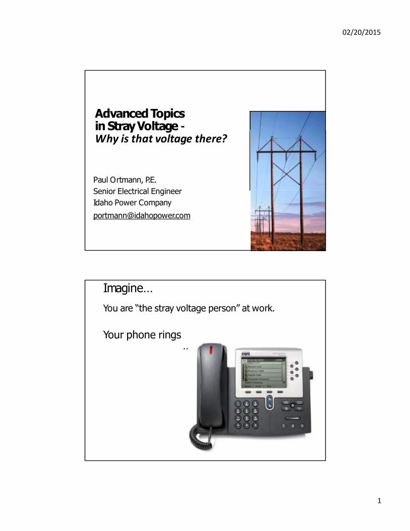
Advanced Topics in Stray Voltage ‐ Why is that voltage there?
Paul Ortmann, P.E.
Senior Electrical Engineer
Idaho Power Company
Imagine…
You are “the stray voltage person” at work.
Your phone rings
…
1
02/20/2015
Five phone calls…
1. Blown transformer fuse, voltage normal.
2. Customer shocked from aluminum siding, where is the fault?
3. Worker shocked on grounded pivot sprinkler.
4. Gas company tech finds about 60V AC between gas pipeline and earth.
5. High frequency NEV and contact voltage.
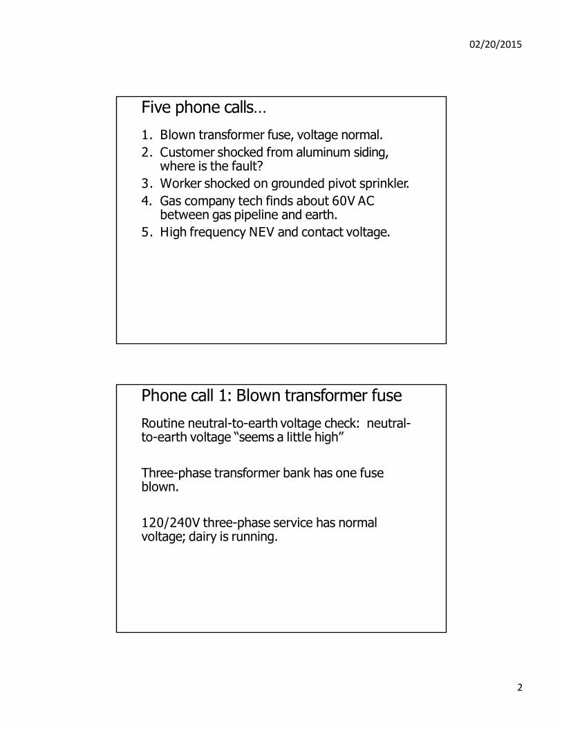
Phone call 1: Blown transformer fuse
Routine neutral-to-earth voltage check: neutral- to-earth voltage “seems a little high”
Three-phase transformer bank has one fuse blown.
120/240V three-phase service has normal voltage; dairy is running.
2
02/20/2015
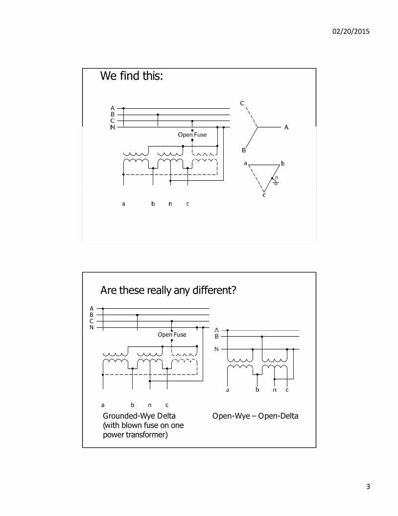
We find this:
Are these really any different?
A B C N
Open Fuse
a b n c
Grounded-Wye Delta (with blown fuse on one power transformer)
Open-Wye – Open-Delta
3
02/20/2015
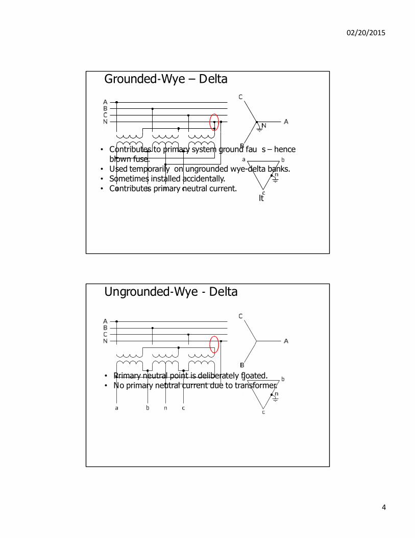
Grounded‐Wye – Delta
• Contributes to primary system ground fau s – hence
blown fuse. • Used temporarily on ungrounded wye-delta banks. • Sometimes installed accidentally. • Contributes primary neutral current.
lt
Ungrounded‐Wye ‐ Delta
• Primary neutral point is deliberately floated. • No primary neutral current due to transformer.
4
02/20/2015
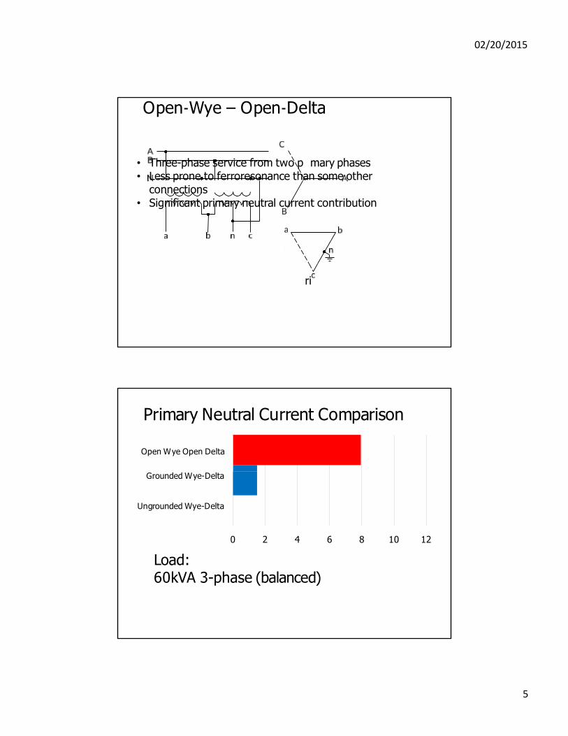
Open‐Wye – Open‐Delta
• Three-phase service from two p mary phases • Less prone to ferroresonance than some other
connections • Significant primary neutral current contribution
ri
Primary Neutral Current Comparison
Open Wye Open Delta
Grounded Wye-Delta
Ungrounded Wye-Delta
0 2 4
Load: 60kVA 3-phase (balanced)
6 8 10 12
5
02/20/2015
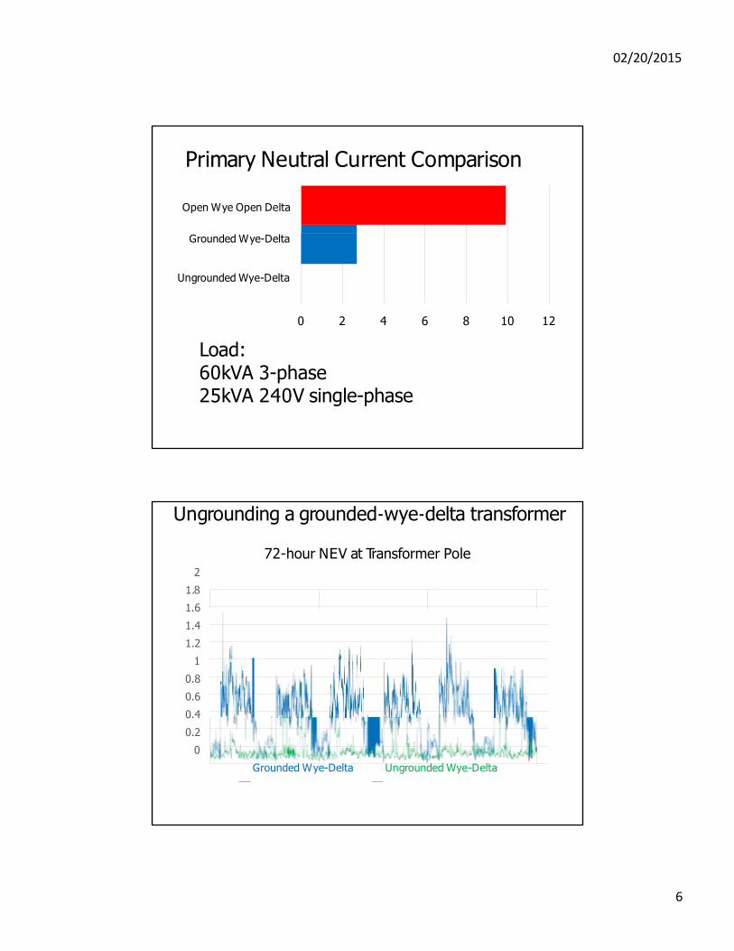
Primary Neutral Current Comparison
Open Wye Open Delta
Grounded Wye-Delta
Ungrounded Wye-Delta
0 2 4
Load: 60kVA 3-phase 25kVA 240V single-phase
6 8 10 12
Ungrounding a grounded‐wye‐delta transformer
72-hour NEV at Transformer Pole 2
1.8
1.6
1.4
1.2
1
0.8
0.6
0.4
0.2
0
Grounded Wye-Delta Ungrounded Wye-Delta
6
02/20/2015
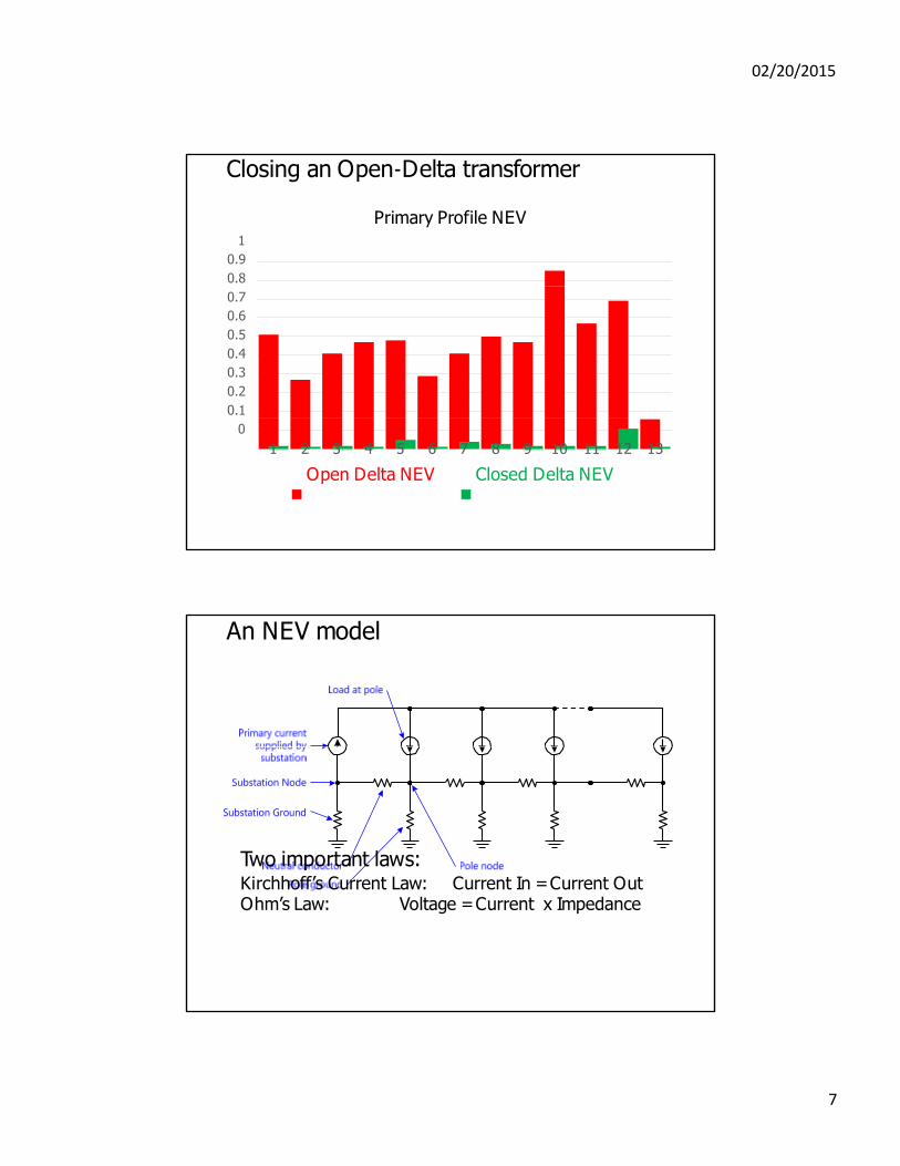
Closing an Open‐Delta transformer
Primary Profile NEV 1
0.9
0.8
0.7
0.6
0.5
0.4
0.3
0.2
0.1
0
1 2 3 4 5 6 7 8 9 10 11 12 13
Open Delta NEV Closed Delta NEV
An NEV model
Two important laws: Kirchhoff’s Current Law: Current In = Current Out Ohm’s Law: Voltage = Current x Impedance
7
02/20/2015
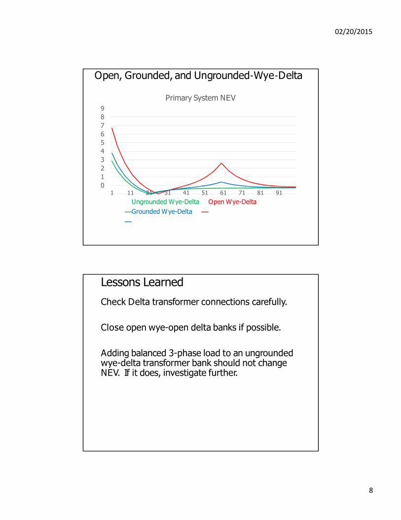
Open, Grounded, and Ungrounded‐Wye‐Delta
Primary System NEV
9
8
7
6
5
4
3
2
1
0 1 11 21 31 41 51 61 71 81 91
Ungrounded Wye-Delta Open Wye-Delta
Grounded Wye-Delta
8
Lessons Learned
Check Delta transformer connections carefully.
Close open wye-open delta banks if possible.
Adding balanced 3-phase load to an ungrounded wye-delta transformer bank should not change NEV. If it does, investigate further.
02/20/2015
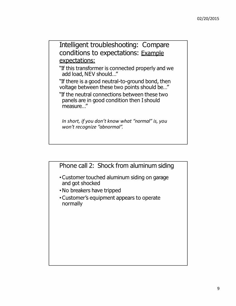
Intelligent troubleshooting: Compare conditions to expectations: Example expectations:
“If this transformer is connected properly and we add load, NEV should…”
“If there is a good neutral-to-ground bond, then voltage between these two points should be…”
“If the neutral connections between these two panels are in good condition then I should measure…”
In short, if you don’t know what “normal” is, you won’t recognize “abnormal”.
9
Phone call 2: Shock from aluminum siding
•Customer touched aluminum siding on garage and got shocked
•No breakers have tripped
•Customer’s equipment appears to operate normally
02/20/2015
Ground faults and effective current paths: From the 2014 NEC: (paraphrased)
•Ground Fault. An unintentional connection between an ungrounded conductor and the normally non–current-carrying conductors, metallic enclosures, metallic raceways, metallic equipment, or earth.
•Effective Ground-Fault Current Path. An intentional, low-impedance path to carry current under ground-fault conditions and facilitates the operation of the overcurrent protective device or ground-fault detectors.
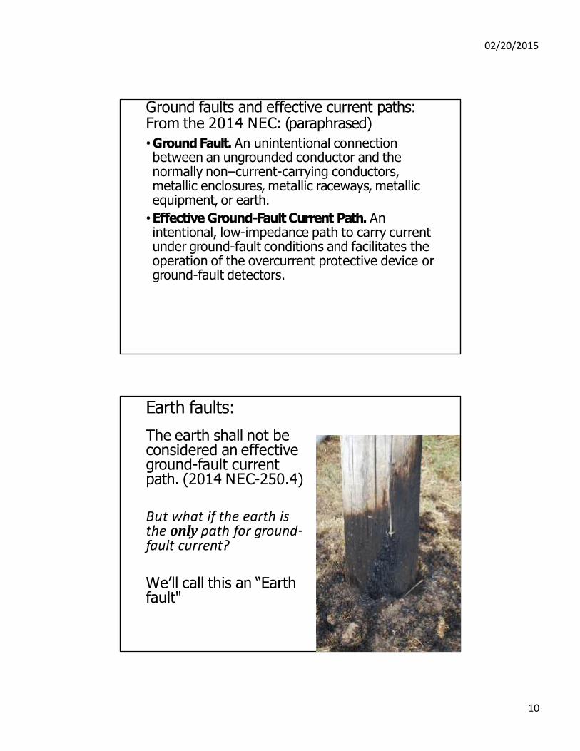
Earth faults:
The earth shall not be considered an effective ground-fault current path. (2014 NEC-250.4)
But what if the earth is the only path for ground‐ fault current?
We’ll call this an “Earth fault"
10
02/20/2015
Observations:
•Separate garage has a short 3-wire 120/240V overhead service from a breaker in the house panel.
•Garage has a subpanel with a main breaker and several branch circuit breakers.
•No GFCI circuit breakers or receptacles are installed in garage.
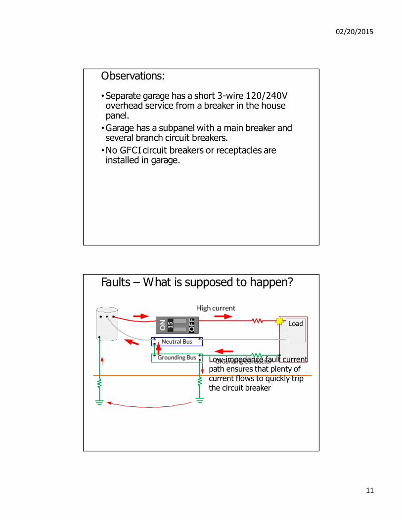
Faults – What is supposed to happen?
Low-impedance fault current path ensures that plenty of current flows to quickly trip the circuit breaker
11
02/20/2015
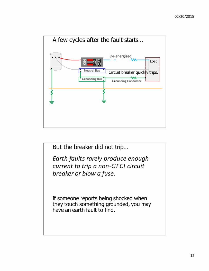
A few cycles after the fault starts…
Circuit breaker quickly trips.
But the breaker did not trip…
Earth faults rarely produce enough current to trip a non‐GFCI circuit breaker or blow a fuse.
If someone reports being shocked when they touch something grounded, you may have an earth fault to find.
12
02/20/2015
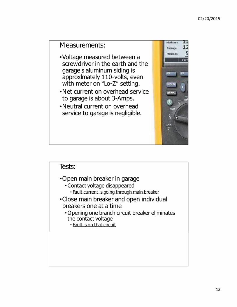
Measurements:
•Voltage measured between a screwdriver in the earth and the garage s aluminum siding is approximately 110-volts, even with meter on “Lo-Z” setting.
•Net current on overhead service to garage is about 3-Amps.
•Neutral current on overhead service to garage is negligible.
’
Tests:
•Open main breaker in garage •Contact voltage disappeared
• Fa ult current is going through main breaker
•Close main breaker and open individual breakers one at a time •Opening one branch circuit breaker eliminates the contact voltage • Fault is on that circuit
13
02/20/2015
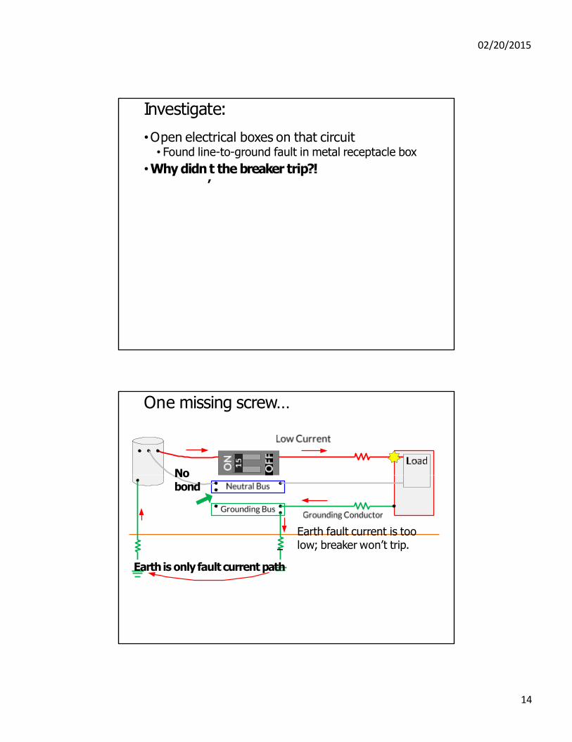
Investigate:
•Open electrical boxes on that circuit • Found line-to-ground fault in metal receptacle box
•Why didn t the breaker trip?!
’
One missing screw…
No bond
Earth fault current is too low; breaker won’t trip.
Earth is only fault current path
14
02/20/2015
Lessons Learned:
If a “ground fault” doesn’t cause a circuit breaker to trip or a fuse to blow, it may actually be an “Earth fault.”
Earth faults are a combination of two problems:
Problem 1: The ground fault
Problem 2: A poor fault current path
Both problems must be found!
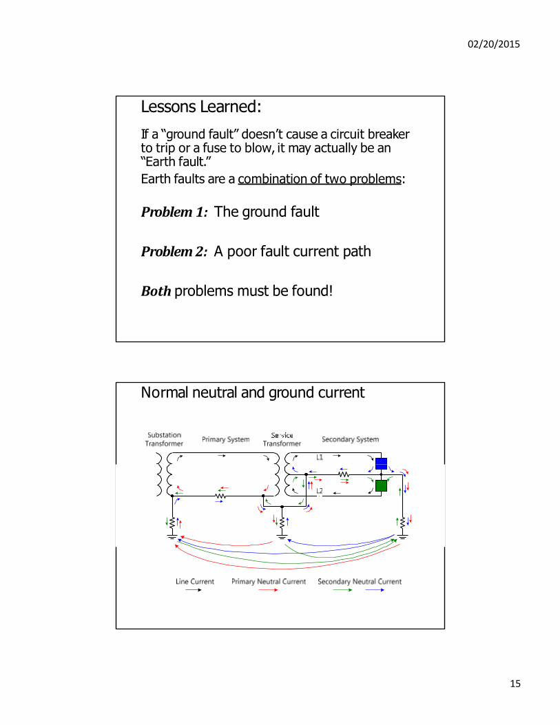
Normal neutral and ground current
15
02/20/2015
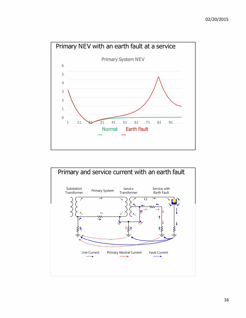
Primary NEV with an earth fault at a service
Primary System NEV 6
5
4
3
2
1
0
1 11 21 31 41 51 61 71 81 91
Normal Earth Fault
Primary and service current with an earth fault
16
02/20/2015
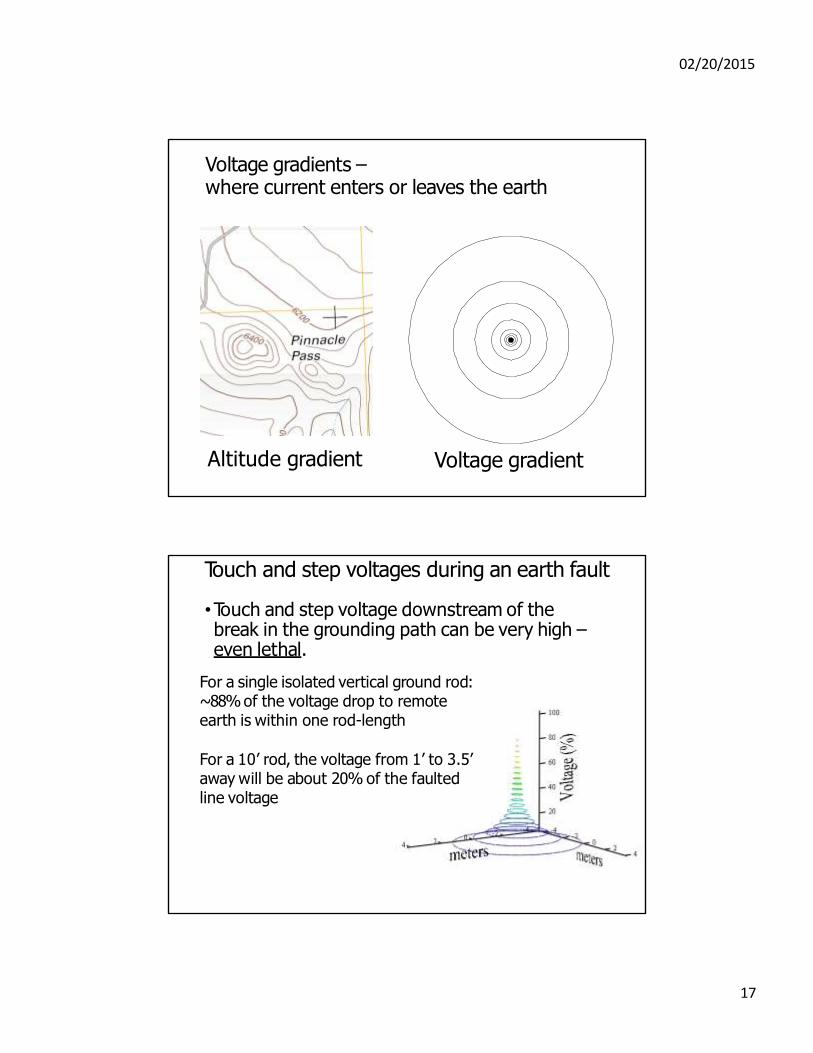
Voltage gradients – where current enters or leaves the earth
Altitude gradient Voltage gradient
Touch and step voltages during an earth fault
•Touch and step voltage downstream of the break in the grounding path can be very high – even lethal.
For a single isolated vertical ground rod: ~88% of the voltage drop to remote earth is within one rod-length
For a 10’ rod, the voltage from 1’ to 3.5’ away will be about 20% of the faulted line voltage
17
02/20/2015
Finding both parts of the earth fault
•The ground fault: 1 . Monitor the fault safely while opening
circuit breakers, fuses, or disconnects. • Multimeter or voltage detector can be used.
• Can measure contact voltage, gradient, or NEV.
2. Do not assume that first upstream device will interrupt fault current.
3. When opening a disconnect de-energizes the fault, the ground fault is downstream of that disconnect and upstream of other disconnects further downstream.
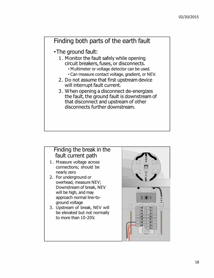
Finding the break in the fault current path
1 . Measure voltage across connections; should be nearly zero
2. For underground or overhead, measure NEV; Downstream of break, NEV will be high, and may approach normal line-to- ground voltage
3. Upstream of break, NEV will be elevated but not normally to more than 10-20V.
18
02/20/2015
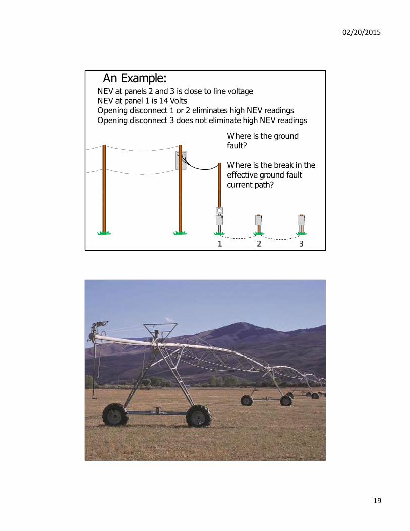
An Example: NEV at panels 2 and 3 is close to line voltage NEV at panel 1 is 14 Volts Opening disconnect 1 or 2 eliminates high NEV readings Opening disconnect 3 does not eliminate high NEV readings
Where is the ground fault?
Where is the break in the effective ground fault current path?
Phone call 3: The shocking pivot
19
02/20/2015
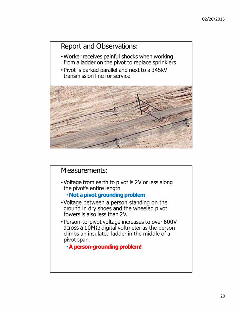
Report and Observations:
•Worker receives painful shocks when working from a ladder on the pivot to replace sprinklers
•Pivot is parked parallel and next to a 345kV transmission line for service
Measurements:
•Voltage from earth to pivot is 2V or less along the pivot’s entire length •Not a pivot grounding problem
•Voltage between a person standing on the ground in dry shoes and the wheeled pivot towers is also less than 2V.
•Person-to-pivot voltage increases to over 600V across a 10MΩ digital voltmeter as the person climbs an insulated ladder in the middle of a pivot span.
•A person-grounding problem!
20
02/20/2015
Electric Field Calculations:
•Open-circuit person-to-pivot AC voltage with person on insulated ladder: Over 10kV! •No wonder it hurts…
•The pivot is not shocking the worker. The worker is shocking the pivot! The effect is very similar to a fencer pulse.
•Steady-state short circuit current for person at working height is less than 0.1mA •Not a steady-state problem if person can be kept grounded.
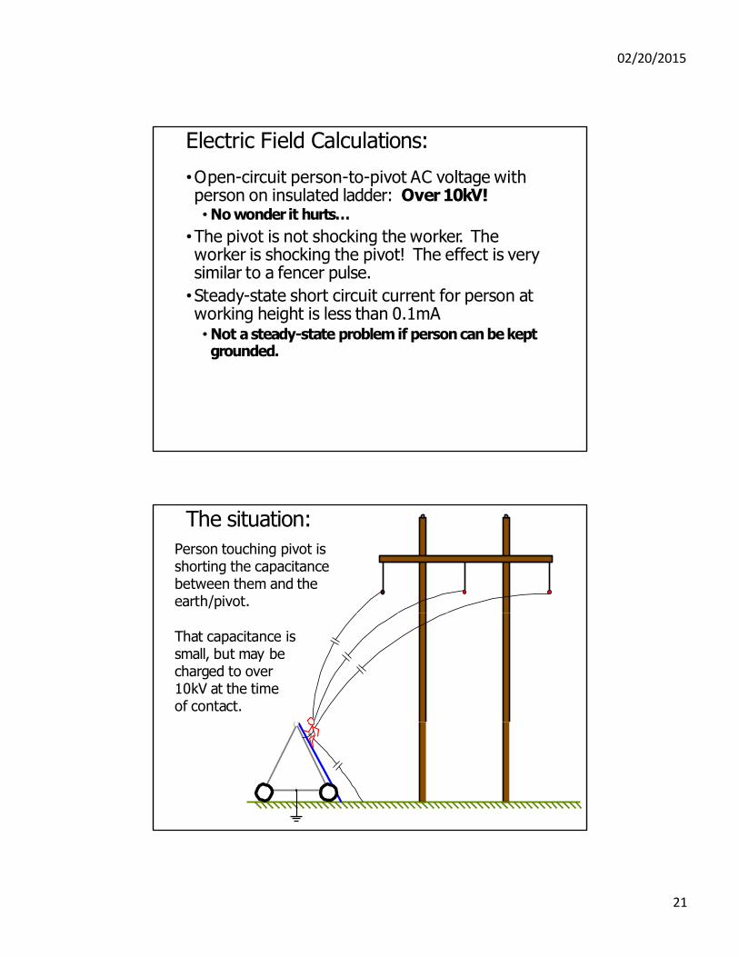
The situation:
Person touching pivot is shorting the capacitance between them and the earth/pivot.
That capacitance is small, but may be charged to over 10kV at the time of contact.
21
02/20/2015
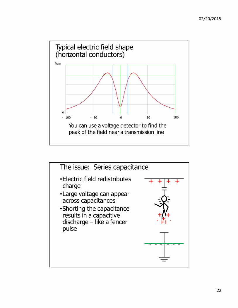
Typical electric field shape (horizontal conductors) V/m
0
- 100 - 50 0 50
You can use a voltage detector to find the peak of the field near a transmission line
100
The issue: Series capacitance
•Electric field redistributes charge
•Large voltage can appear across capacitances
•Shorting the capacitance results in a capacitive discharge – like a fencer pulse
22
02/20/2015
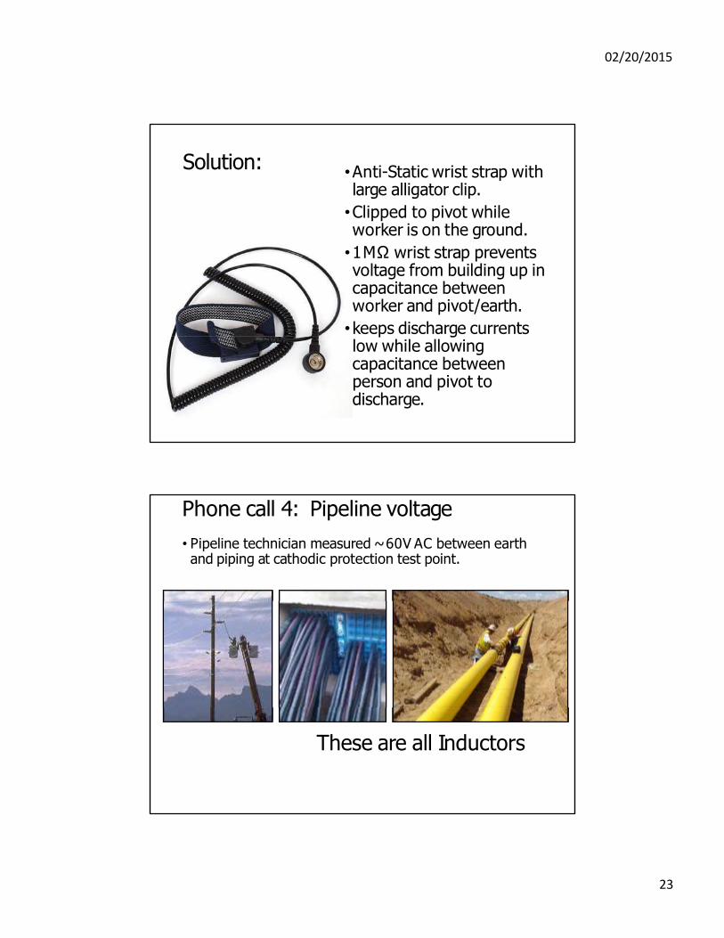
Solution: •Anti-Static wrist strap with large alligator clip.
•Clipped to pivot while worker is on the ground.
•1MΩ wrist strap prevents voltage from building up in capacitance between worker and pivot/earth.
•keeps discharge currents low while allowing capacitance between person and pivot to discharge.
Phone call 4: Pipeline voltage
• Pipeline technician measured ~ 60V AC between earth and piping at cathodic protection test point.
These are all Inductors
23
02/20/2015
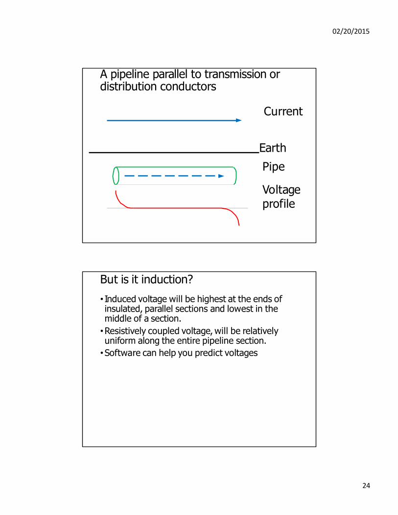
A pipeline parallel to transmission or distribution conductors
Current
Earth
Pipe
Voltage profile
But is it induction?
• Induced voltage will be highest at the ends of insulated, parallel sections and lowest in the middle of a section.
•Resistively coupled voltage, will be relatively uniform along the entire pipeline section.
•Software can help you predict voltages
24
02/20/2015
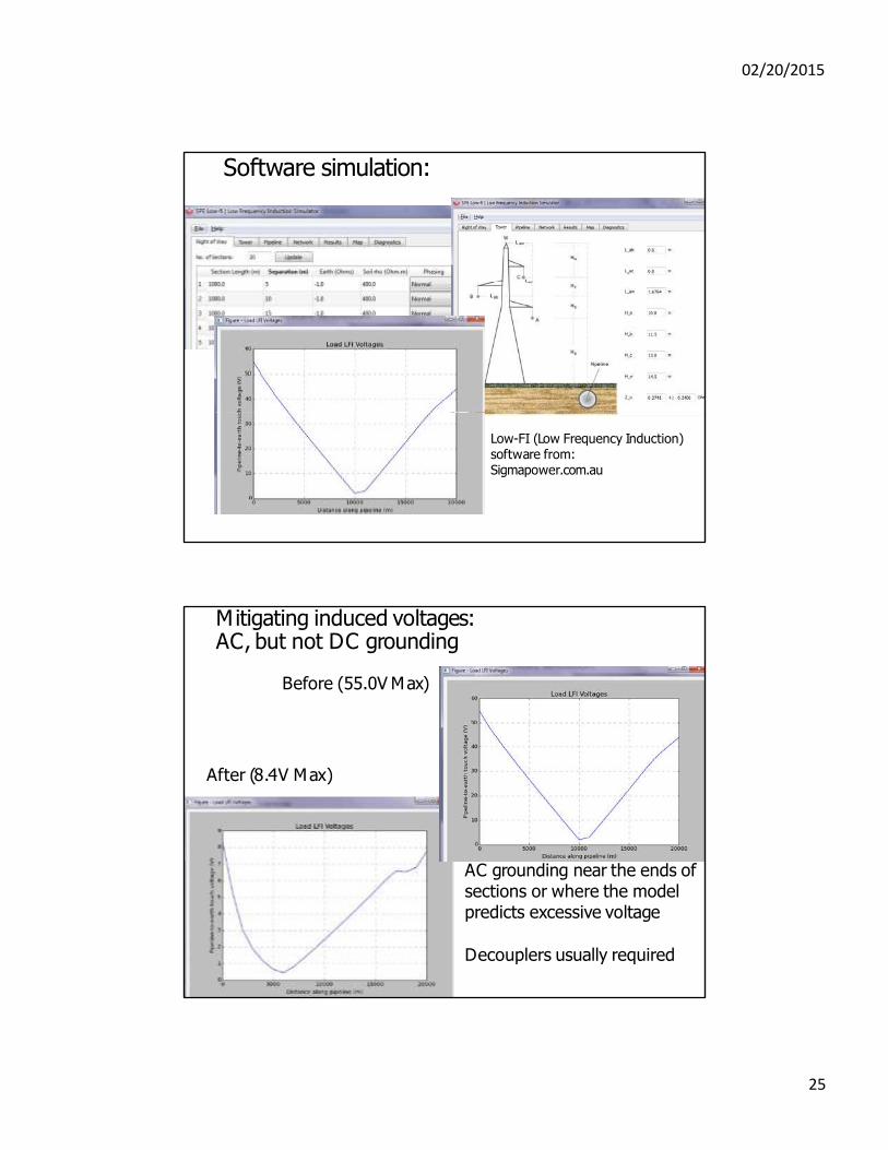
Software simulation:
Low-FI (Low Frequency Induction) software from: Sigmapower.com.au
Mitigating induced voltages: AC, but not DC grounding
Before (55.0V Max)
After (8.4V Max)
AC grounding near the ends of sections or where the model predicts excessive voltage
Decouplers usually required
25
02/20/2015
Phone call 5: High frequency issues
•Call starts as a “routine” stray voltage call
•Spot-measured NEV at service is surprisingly high (>5V).
•SVM-10 stray voltage recorder doesn’t record NEV that high.
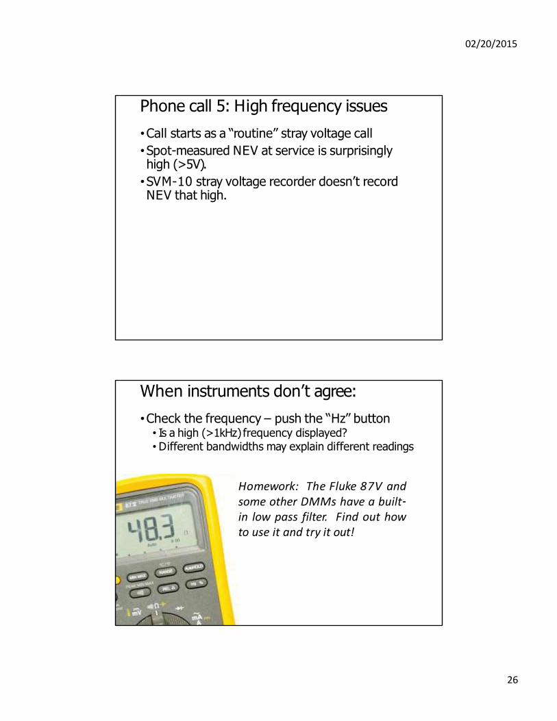
When instruments don’t agree:
•Check the frequency – push the “Hz” button • Is a high (>1kHz) frequency displayed? •Different bandwidths may explain different readings
Homework: The Fluke 87V and some other DMMs have a built‐ in low pass filter. Find out how to use it and try it out!
26
02/20/2015
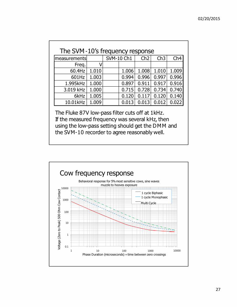
The SVM ‐10’s frequency response
The Fluke 87V low-pass filter cuts off at 1kHz. If the measured frequency was several kHz, then using the low-pass setting should get the DMM and the SVM-10 recorder to agree reasonably well.
Cow frequency response Behavioral response for 5% most sensitive cows, sine waves
muzzle to hooves exposure 10000
1 cycle Biphasic
1 cycle Monophasic 1000
Multi Cycle
100
Voltage (
Zero
to P
eak)
500 O
hm
Cow
Conta
ct
10
0.1
1
1 10 100 1000
Phase Duration (microseconds) = time between zero crossings
10000
27
measurements SVM-10 Ch1 Ch2 Ch3 Ch4
Freq. V
60.4Hz 1.010 1.006 1.008 1.010 1.009
601Hz 1.003 0.994 0.996 0.997 0.996
1.995kHz 1.000 0.897 0.911 0.917 0.916
3.019 kHz 1.000 0.715 0.728 0.734 0.740
6kHz 1.005 0.120 0.117 0.120 0.140
10.01kHz 1.009 0.013 0.013 0.012 0.022
02/20/2015
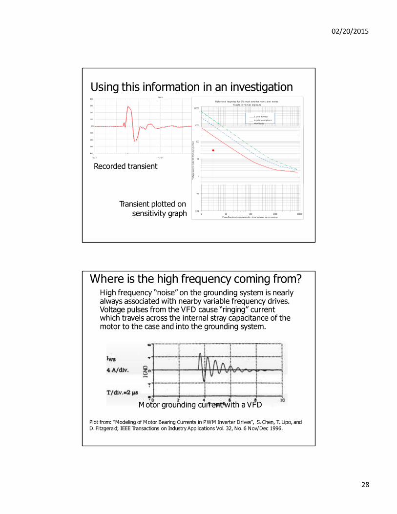
Using this information in an investigation Behavioral response for 5% most sensitive cows, sine waves
muzzle to hooves exposure
10000
1 cycle Biphasic
1 cycle Monophasic
Multi Cycle 1000
1
10
Recorded transient
100
Vo
ltag
e (Z
ero
to P
eak) 500 O
hm
Co
w C
on
tact
0.01
0.1
1 10 100 1000
Phase Duration (microseconds) = time between zero crossings
10000
Transient plotted on sensitivity graph
Where is the high frequency coming from? High frequency “noise” on the grounding system is nearly always associated with nearby variable frequency drives. Voltage pulses from the VFD cause “ringing” current which travels across the internal stray capacitance of the motor to the case and into the grounding system.
Motor grounding current with a VFD
Plot from: “Modeling of Motor Bearing Currents in PWM Inverter Drives”, S. Chen, T. Lipo, and D. Fitzgerald; IEEE Transactions on Industry Applications Vol. 32, No. 6 Nov/Dec 1996.
28
02/20/2015
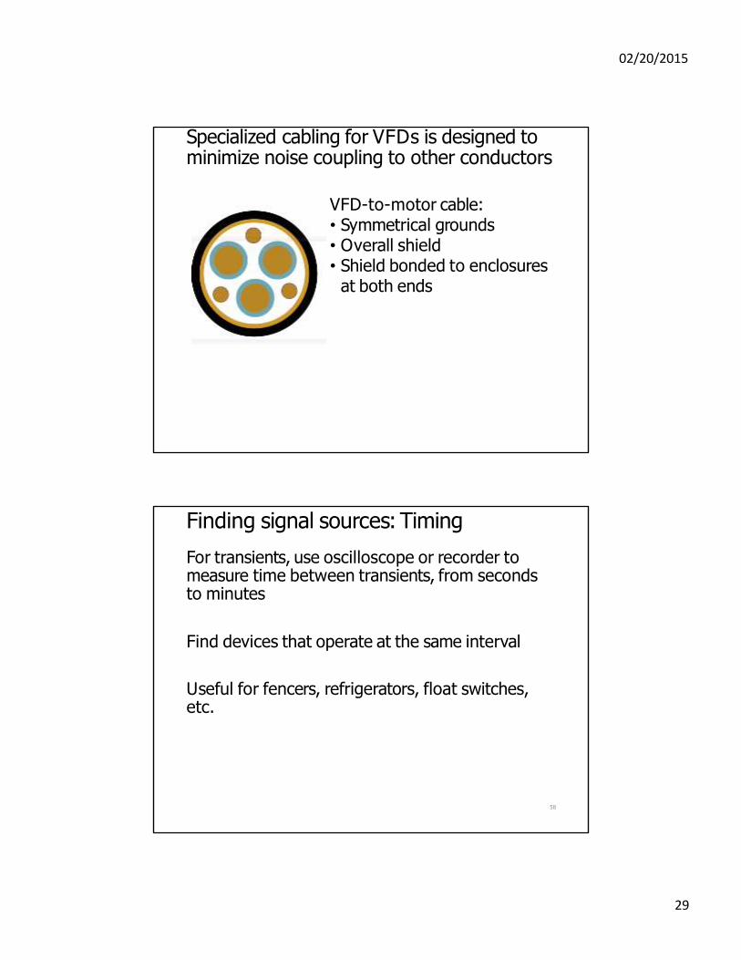
Specialized cabling for VFDs is designed to minimize noise coupling to other conductors
VFD-to-motor cable: • Symmetrical grounds • Overall shield • Shield bonded to enclosures
at both ends
Finding signal sources: Timing
For transients, use oscilloscope or recorder to measure time between transients, from seconds to minutes
Find devices that operate at the same interval
Useful for fencers, refrigerators, float switches, etc.
58
29
02/20/2015
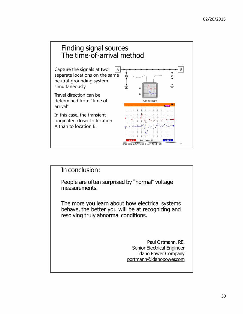
Finding signal sources The time‐of‐arrival method
B
A
B
Oscilloscope
59
Capture the signals at two A
separate locations on the same
neutral-grounding system
simultaneously
Travel direction can be
determined from “time of
arrival”
In this case, the transient
originated closer to location
A than to location B.
In conclusion:
People are often surprised by “normal” voltage measurements.
The more you learn about how electrical systems behave, the better you will be at recognizing and resolving truly abnormal conditions.
Paul Ortmann, P.E.
Senior Electrical Engineer Idaho Power Company
30