Embed Size (px)
Citation preview

Advanced Surface Modeling for Solid Edge
Rhinoceros® NURBS modeling for Windows

Rhinoceros: Advanced Surface Modeling for Solid Edge
2
Advanced Surface Modeling With Rhino you can enhance the modeling features of Solid Edge in several important ways. You can:
• Create and analyze advanced, free-form surfaces
Free-form surface.
• Fix IGES files
Badly trimmed IGES file.
• Translate 3-D data between applications
• Edit 3-D data from diverse sources
Rhinoceros: Advanced Surface Modeling for Solid Edge
3
Create Advanced Free-form Surfaces Rhino can be used to create very accurate, free-form surface and solid models for import into Solid Edge. These models can be used as body features, as reference geometry, or as replacement faces to solids with association for future updates.
Modeling in Rhino is different from modeling in Solid Edge and other parametric, feature-based modelers. In Solid Edge, you start with a sketch or body feature and then add features to create a command history tree. Rhino does not maintain a command history tree and has no parametric features. This frees you to work directly with solids, curves, and advanced surfaces without regard for command history or embedded sketches. Curves are used to make surfaces. Surfaces are created, trimmed, matched, evaluated, and if desired, joined into open or closed polysurfaces. Rhino supports Boolean operations on both open and closed polysurfaces.
A closed polysurface defines a volume and can be exported as an IGES, STEP, or Parasolid file and imported into Solid Edge as a body feature.
Surfaces and open polysurfaces can be imported and thickened into body features or used to replace faces on solids. If the Rhino surface was exported as a Parasolid file, an association is created, and subsequent edits of the surface in Rhino can be updated into Solid Edge without losing the command history structure.
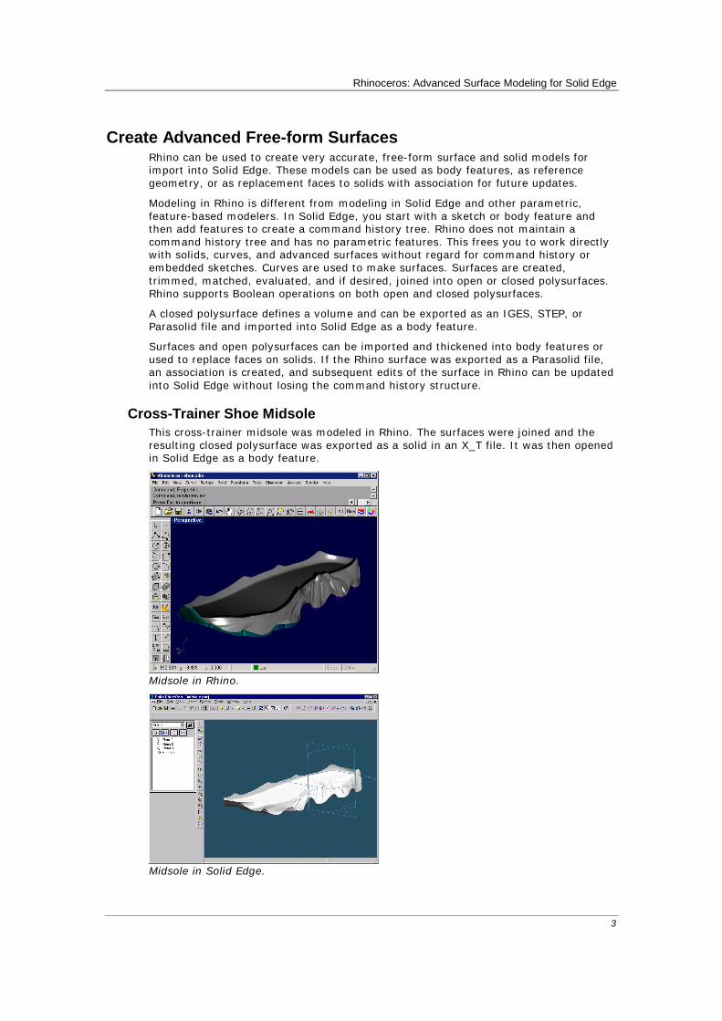
Cross-Trainer Shoe Midsole This cross-trainer midsole was modeled in Rhino. The surfaces were joined and the resulting closed polysurface was exported as a solid in an X_T file. It was then opened in Solid Edge as a body feature.
Midsole in Rhino.
Midsole in Solid Edge.

Rhinoceros: Advanced Surface Modeling for Solid Edge
4
Automobile Fender The following car fender was designed and built in Rhino. In this example the main body of the fender and the lip are to be joined with a special surface between them. This surface must have curvature (G2) continuity with the adjacent surfaces to avoid visual seams in reflections. Rhino features high-end, feature-rich, surface modeling tools, including position, tangency, and curvature matching as shown in the following example.
This surface is created from a curve network.
The NetworkSrf command is used in this case. The edges of the adjacent surfaces and previously drawn profile curves are selected as input for the command. The profile curves indicate the desired surface shape to the command. The surface edges labeled B and D have been designated for curvature (G2) matching. G2 curvature indicates the second derivative of the surface curves is equal at those edges. This ensures that there will be no visible seam in reflections on this fender.
The resulting surface.
Rhinoceros: Advanced Surface Modeling for Solid Edge
5
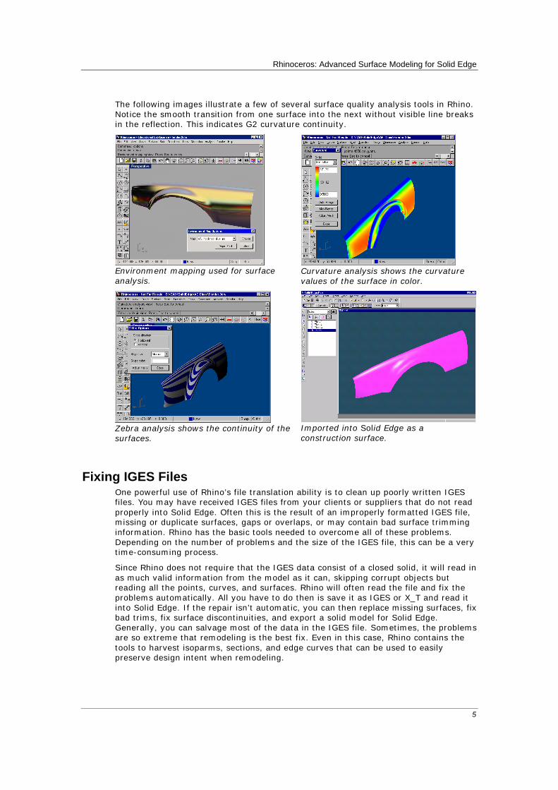
The following images illustrate a few of several surface quality analysis tools in Rhino. Notice the smooth transition from one surface into the next without visible line breaks in the reflection. This indicates G2 curvature continuity.
Environment mapping used for surface analysis.
Curvature analysis shows the curvature values of the surface in color.
Zebra analysis shows the continuity of the surfaces.
Imported into Solid Edge as a construction surface.
Fixing IGES Files One powerful use of Rhino’s file translation ability is to clean up poorly written IGES files. You may have received IGES files from your clients or suppliers that do not read properly into Solid Edge. Often this is the result of an improperly formatted IGES file, missing or duplicate surfaces, gaps or overlaps, or may contain bad surface trimming information. Rhino has the basic tools needed to overcome all of these problems. Depending on the number of problems and the size of the IGES file, this can be a very time-consuming process.
Since Rhino does not require that the IGES data consist of a closed solid, it will read in as much valid information from the model as it can, skipping corrupt objects but reading all the points, curves, and surfaces. Rhino will often read the file and fix the problems automatically. All you have to do then is save it as IGES or X_T and read it into Solid Edge. If the repair isn’t automatic, you can then replace missing surfaces, fix bad trims, fix surface discontinuities, and export a solid model for Solid Edge. Generally, you can salvage most of the data in the IGES file. Sometimes, the problems are so extreme that remodeling is the best fix. Even in this case, Rhino contains the tools to harvest isoparms, sections, and edge curves that can be used to easily preserve design intent when remodeling.
Rhinoceros: Advanced Surface Modeling for Solid Edge
6
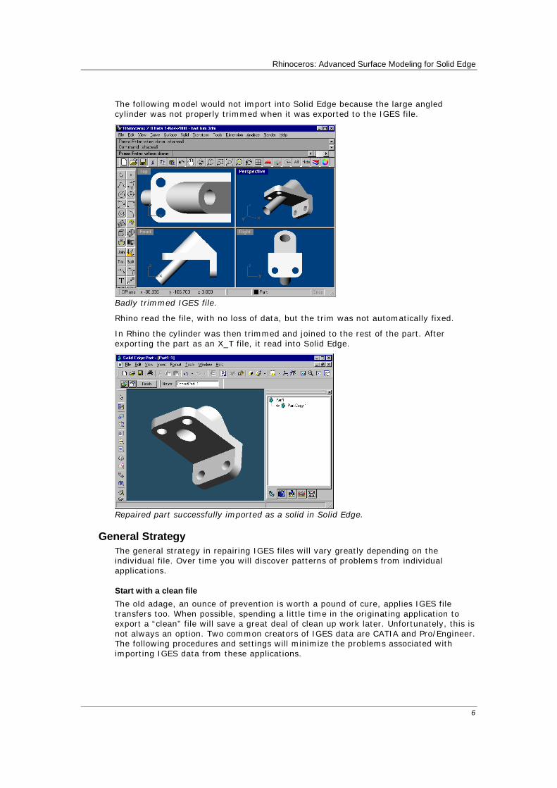
The following model would not import into Solid Edge because the large angled cylinder was not properly trimmed when it was exported to the IGES file.
Badly trimmed IGES file.
Rhino read the file, with no loss of data, but the trim was not automatically fixed.
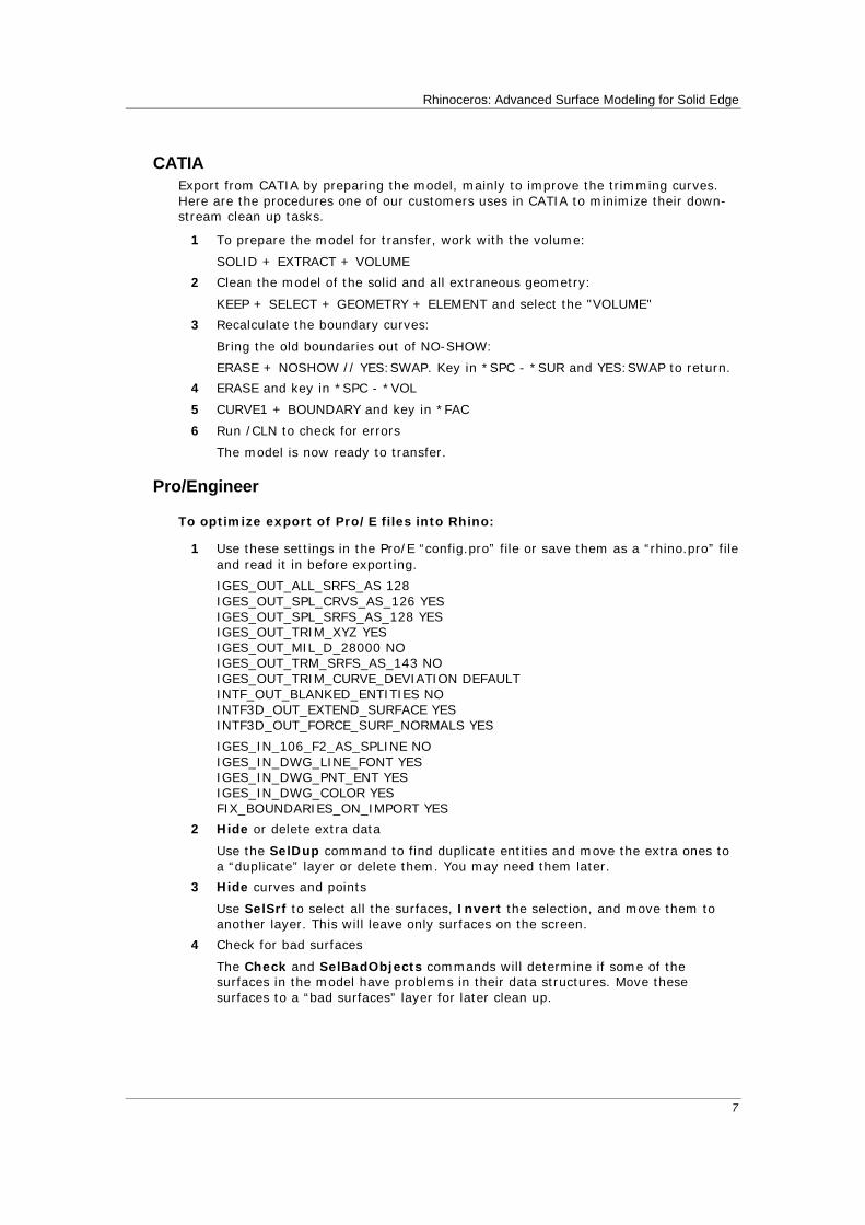
In Rhino the cylinder was then trimmed and joined to the rest of the part. After exporting the part as an X_T file, it read into Solid Edge.
Repaired part successfully imported as a solid in Solid Edge.
General Strategy The general strategy in repairing IGES files will vary greatly depending on the individual file. Over time you will discover patterns of problems from individual applications.
Start with a clean file The old adage, an ounce of prevention is worth a pound of cure, applies IGES file transfers too. When possible, spending a little time in the originating application to export a “clean” file will save a great deal of clean up work later. Unfortunately, this is not always an option. Two common creators of IGES data are CATIA and Pro/Engineer. The following procedures and settings will minimize the problems associated with importing IGES data from these applications.
Rhinoceros: Advanced Surface Modeling for Solid Edge
7
CATIA Export from CATIA by preparing the model, mainly to improve the trimming curves. Here are the procedures one of our customers uses in CATIA to minimize their down-stream clean up tasks.
1 To prepare the model for transfer, work with the volume:
SOLID + EXTRACT + VOLUME
2 Clean the model of the solid and all extraneous geometry:
KEEP + SELECT + GEOMETRY + ELEMENT and select the "VOLUME"
3 Recalculate the boundary curves:
Bring the old boundaries out of NO-SHOW:
ERASE + NOSHOW // YES:SWAP. Key in *SPC - *SUR and YES:SWAP to return.
4 ERASE and key in *SPC - *VOL
5 CURVE1 + BOUNDARY and key in *FAC
6 Run /CLN to check for errors
The model is now ready to transfer.
Pro/Engineer
To optimize export of Pro/E files into Rhino:
1 Use these settings in the Pro/E “config.pro” file or save them as a “rhino.pro” file and read it in before exporting.
IGES_OUT_ALL_SRFS_AS 128 IGES_OUT_SPL_CRVS_AS_126 YES IGES_OUT_SPL_SRFS_AS_128 YES IGES_OUT_TRIM_XYZ YES IGES_OUT_MIL_D_28000 NO IGES_OUT_TRM_SRFS_AS_143 NO IGES_OUT_TRIM_CURVE_DEVIATION DEFAULT INTF_OUT_BLANKED_ENTITIES NO INTF3D_OUT_EXTEND_SURFACE YES INTF3D_OUT_FORCE_SURF_NORMALS YES
IGES_IN_106_F2_AS_SPLINE NO IGES_IN_DWG_LINE_FONT YES IGES_IN_DWG_PNT_ENT YES IGES_IN_DWG_COLOR YES FIX_BOUNDARIES_ON_IMPORT YES
2 Hide or delete extra data
Use the SelDup command to find duplicate entities and move the extra ones to a “duplicate” layer or delete them. You may need them later.
3 Hide curves and points
Use SelSrf to select all the surfaces, Invert the selection, and move them to another layer. This will leave only surfaces on the screen.
4 Check for bad surfaces
The Check and SelBadObjects commands will determine if some of the surfaces in the model have problems in their data structures. Move these surfaces to a “bad surfaces” layer for later clean up.
Rhinoceros: Advanced Surface Modeling for Solid Edge
8
5 Shade and visually inspect the model
Does it look like you expected it would? Are there obviously missing surfaces? Do surfaces extend beyond where they should? The trimming curves needed to fix them may be on the “duplicate” layer.
6 Look at the absolute modeling tolerance in file properties
Is it reasonable? Free-form surface modeling requires an intelligent compromise in modeling tolerance. NURBS curves are chains of polynomial expression segments joined by knots, that carry continuity information between the segments. These segments are fitted to neighboring curves within the specified modeling tolerance. The tighter the tolerance, the more complex these curves become and system performance suffers. There is no point in calculating high density curve fitting to tolerance values that are not supported by your down-stream manufacturing processes.
7 Join the surfaces
When joining, edges are tagged as joined if they fit within the specified modeling tolerance. If they are outside the tolerance, they are not joined. Joining does not alter the geometry. It only tags the edges as being close enough to be treated as coincidental. Look at the results on the command line. Did you get as many polysurfaces as you thought you would? Sometimes there are double surfaces after importing an IGES file. Usually, one will be complete and the second one will be missing interior trims. When the join happens, you have no control over which of the two surfaces it will select. If you suspect this has occurred, try joining two naked edges. If there is no near by naked edge where one should be, undo the join, and select for duplicate surfaces. Delete the less complete surfaces and try the join again.
8 Check for naked edges
Naked edges are surface edges that don’t connect to anything. During the join process, they were farther apart than the specified modeling tolerance. This may be from sloppy initial modeling, a misleading tolerance setting in the imported IGES file, or duplicate surfaces. If there are too many naked edges showing when you run the ShowNakedEdges command, consider undoing the join and relaxing the absolute tolerance. It is likely that the original modeling was done to a more relaxed tolerance and the exporting to a higher setting.
Note: You can not improve the tolerance fitting between surfaces without substantial remodeling.
9 Join naked edges or remodel
The joining of naked edges can be a mixed blessing. It is a trade off and may cause problems down-stream. If your reason for joining the edges is for later import into Solid Edge as a solid, or a meshing operation like making an STL file, using the JoinEdge command will not generally cause any problems. If you will be cutting sections and most other “curve harvesting” operations, the sections will have gaps as they cross edges that were joined outside of tolerance. The gap to be spanned is displayed prior to joining. If the gap is sell than twice of your tolerance setting, you can proceed without worry. If the gap is too wide, consider editing or rebuilding the surfaces to reduce the gap. Join and JoinEdge do not alter the surface geometry. They only tag edges as accepted as being coincident within the specified or override tolerance.
10 Repair the bad surfaces
It’s best to repair one bad surface at a time, and join them into the polysurface as you go. In order of least destructive method to most radical, the problems that caused them to fail check can be repaired by the following methods:
• Rebuild edges
• Detach trim curves and re-trim
Rhinoceros: Advanced Surface Modeling for Solid Edge
9
• Rebuild surfaces
• Replace surfaces - harvesting edges from surrounding surfaces, cutting sections through bad surfaces and building replacement surfaces from the collected curves.
If a surface fails check reporting that a tedge (trim edge) is not G1, this minor error can be ignored or the multiple span surface can be split on the knots.
11 Check for bad objects
Sometimes joining surfaces that pass check can result in a polysurface that fails check. Generally this is caused by tiny segments in the edge or trimming curves that are shorter than the modeling tolerance. Subtract the adjoining surfaces, check them, edit the boundary curves to eliminate these tiny segments, and join them back in. You are finished when you have a closed polysurface that passes Check and has no naked edges. As you are joining and fixing surfaces, it is generally a good idea to run Check from time to time as you work.
12 Export
Now that the IGES file has been cleaned up and repaired, you can export it as IGES, Parasolid, or STEP for import into Solid Edge. Parasolid is the preferred format for associativity but there are situations where the other file formats are useful. The Parasolid “universe” is defined as a region centered around 0,0,0 that extends 1000 meters in three axes, with 10 x e6 precision. All Parasolid calculations are converted to meters and must fit within this “universe”. If your model is positioned in space and is sized such that it will fall outside this boundary, you will need to move it closer to the origin to avoid translations problems.
Translate 3-D Data Between Applications At the simplest level, Rhino can be used as a powerful file translator. You can accurately share 3-D models with other applications for rendering, animation, drafting, engineering, analysis, and manufacturing.
Supported file formats include:
DWG/DXF (AutoCAD 2000, 14, 13, and 12), SAT (ACIS), X_T (Parasolid), 3DS, LWO, STL, OBJ, AI, RIB, POV, UDO, VRML, BMP, TGA, JPG, CSV (export properties and hydrostatics).
IGES (Alias, Ashlar Vellum, AutoFORM, AutoShip, Breault, CADCEUS, CAMSoft, CATIA, Cosmos, Delcam, FastSurf, FastSHIP, Integrity Ware, IronCAD, LUSAS, Maya, MAX 3.0, Mastercam, ME30, Mechanical Desktop, Microstation, NuGraf, OptiCAD, Pro/E, SDRC I-DEAS, Softimage, Solid Edge, SolidWorks, SUM 4, SURFCAM, TeKSoft, Unigraphics).
Most of the commonly used file formats are represented here, and new formats are added to Rhino as needed.
With these file formats, you can use sketches, drawings, or 3-D models from just about anywhere as a basis for your model including parts that have already been modeled in Solid Edge.
Modifying Solid Edge geometry with Rhino One powerful use of Rhino with Solid Edge is to use Rhino to make a required complicated surface to replace the face of a body in Solid Edge. If this is done using a Parasolid file from Rhino, an association is set up linking the part face to the Parasolid file. If the surface is revised, the change will be reflected in Solid edge without destroying the command history list.
Rhinoceros: Advanced Surface Modeling for Solid Edge
10
The general steps are:
1. Export a reference part from Solid Edge.
2. In Rhino use the reference part to model a free-form surface.
3. Export the part from Rhino as a Parasolid file.
4. Link the part to Solid Edge.
5. Modify the Rhino part and re-export to linked Parasolid file.
Rhino provides a complete set of surfacing tools to compliment the design process. The following example shows how Rhino can be used to show exporting, surface creation, point editing, embossing text, and associativity between Solid Edge and Rhino using a Parasolid surface.
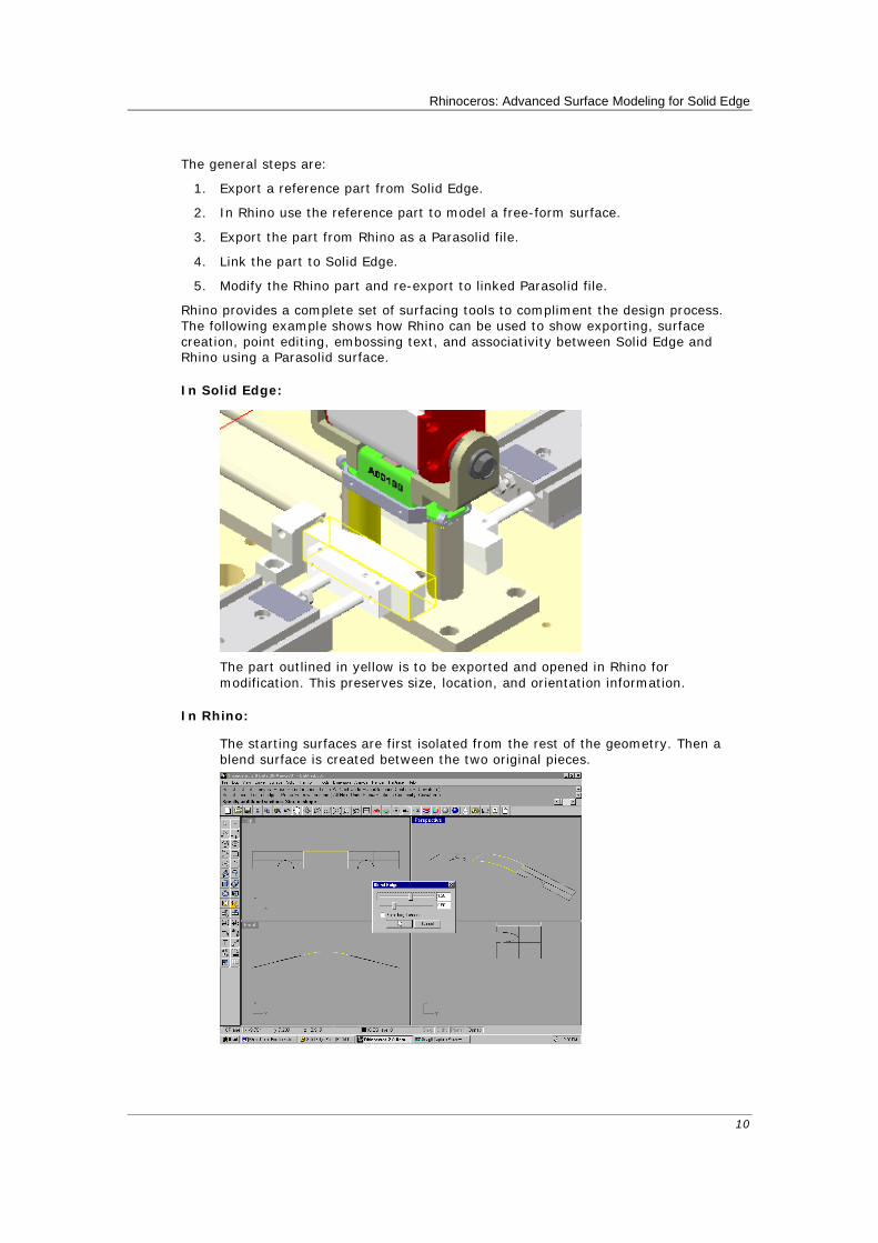
In Solid Edge:
The part outlined in yellow is to be exported and opened in Rhino for
modification. This preserves size, location, and orientation information.
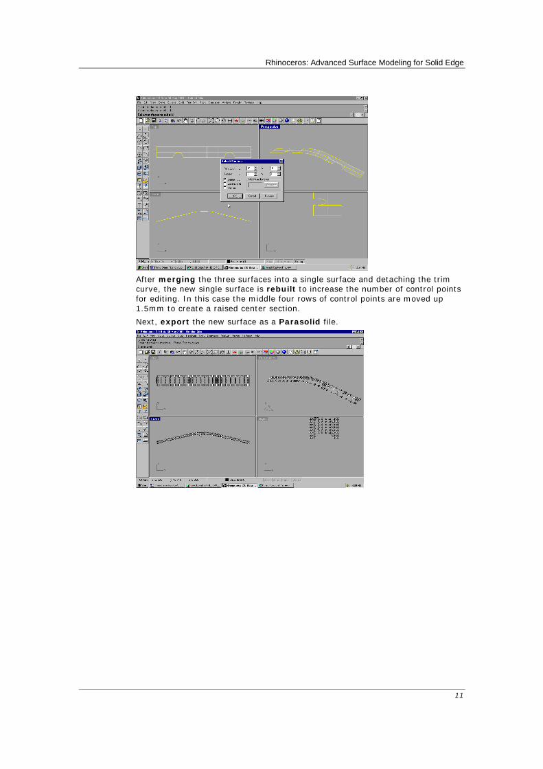
In Rhino:
The starting surfaces are first isolated from the rest of the geometry. Then a blend surface is created between the two original pieces.
Rhinoceros: Advanced Surface Modeling for Solid Edge
11
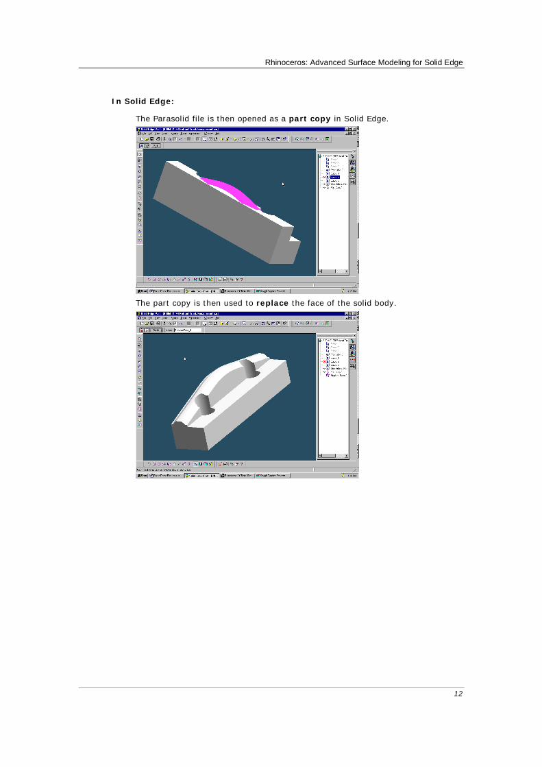
After merging the three surfaces into a single surface and detaching the trim
curve, the new single surface is rebuilt to increase the number of control points for editing. In this case the middle four rows of control points are moved up 1.5mm to create a raised center section.
Next, export the new surface as a Parasolid file.
Rhinoceros: Advanced Surface Modeling for Solid Edge
12
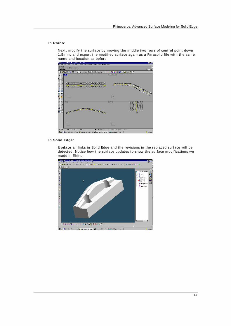
In Solid Edge:
The Parasolid file is then opened as a part copy in Solid Edge.
The part copy is then used to replace the face of the solid body.
Rhinoceros: Advanced Surface Modeling for Solid Edge
13
In Rhino:
Next, modify the surface by moving the middle two rows of control point down 1.5mm, and export the modified surface again as a Parasolid file with the same name and location as before.
In Solid Edge:
Update all links in Solid Edge and the revisions in the replaced surface will be detected. Notice how the surface updates to show the surface modifications we made in Rhino.
Rhinoceros: Advanced Surface Modeling for Solid Edge
14
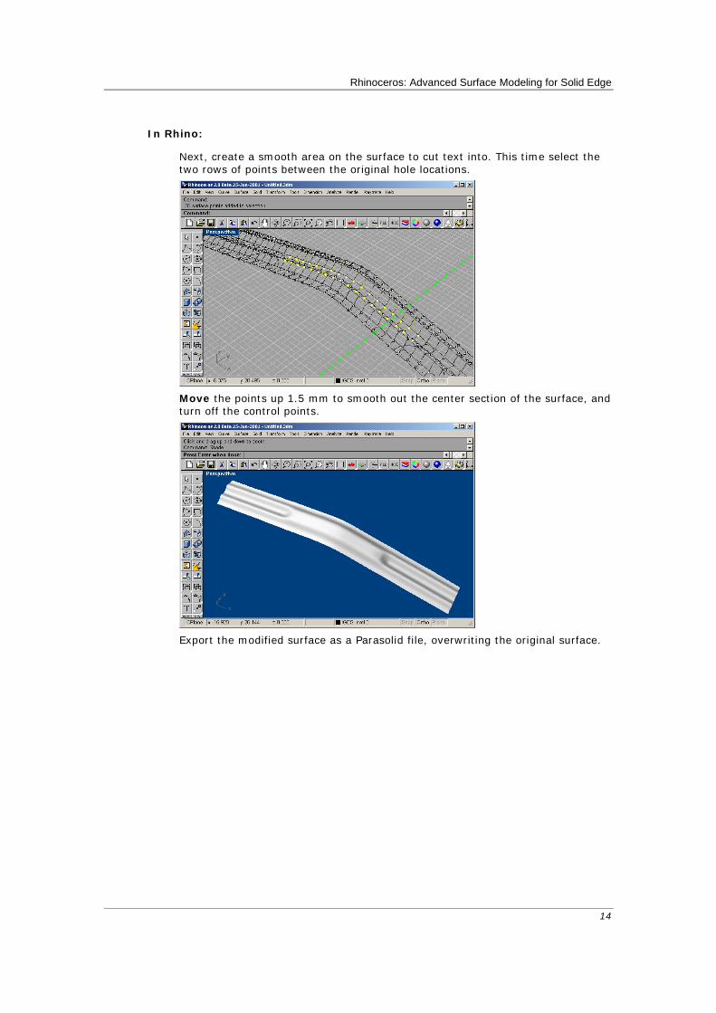
In Rhino:
Next, create a smooth area on the surface to cut text into. This time select the two rows of points between the original hole locations.
Move the points up 1.5 mm to smooth out the center section of the surface, and
turn off the control points.
Export the modified surface as a Parasolid file, overwriting the original surface.

Rhinoceros: Advanced Surface Modeling for Solid Edge
15
In Solid Edge:
Update all links. Notice how the surface in Solid Edge updates to show the surface modifications we made in Rhino.
In Rhino:
Make the Top viewport current. Use the TextObject command to create solid text objects. Any TrueType font can be used to create curves, surfaces, or solids in Rhino. Use the following settings.
Drag the solid text characters so they pass through the surface and are
positioned between the holes.
Use the BooleanDifference command to subtract the lower part of the text
characters from the surface.

Rhinoceros: Advanced Surface Modeling for Solid Edge
16
Your first set of objects is the text characters.
You can use a crossing window to select all of them.
The second set is the surface. Change DeleteInput to No before you finish the selection.
Using the trimmed text to cut away from the surface in Solid Edge.
To make the cut 1 mm deep, we will move them down that much in Rhino.
Select the text and Move it down 1 mm.
Use Export Selected and save it as a Parasolid file under a new name.
In Solid Edge
Insert Part Copy using the Parasolid file you just made in Rhino.
Perform a Boolean Subtract using the part copy as the tool and hide the construction part copy.

Rhinoceros: Advanced Surface Modeling for Solid Edge
17
The modified part (yellow outline) shown back in the main assembly.
Use a 3-D Digitizer to Collect Data Rhino can act as an interface for Microscribe and Faro Space Arm digitizers to gather data or reverse engineer products.
Direct support for MicroScribe and Faro Space Arm 3-D digitizers.
Rhino as Solid Edge Companion Teaming Rhino as a companion application for fixing IGES files, as a file translator, as a tool for creating very accurate complex surfaces, and using data from a wide variety of diverse sources, can dramatically increases the power of Solid Edge. From the above examples, you should now have a basic understanding of how Rhino can extend the reach of Solid Edge more deeply into free-form industrial design and how it can get you out of difficult situations. For more information and to download a full functioning evaluation version, visit www.rhino3d.com.