Embed Size (px)
Citation preview
Advanced Surface NitridingRobert Balerio
October 18, 2016
Texas A&M Nuclear Engineering
Why Nitride
• Low-temperature process• No quench requirement• Minimal distortion• Resistance to oxidation• High hardness values• Same core properties
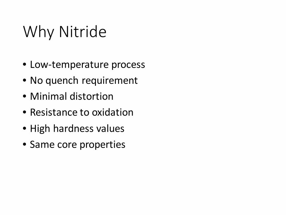
Basic Theory
• Large voltage frees bound electrons
• Particle acceleration• Vacuum increase mfp =>
greater energy• Ions collide to give off
visible light
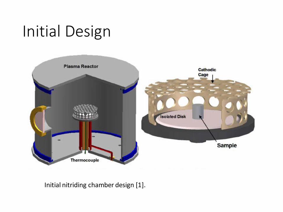
Initial Design
Initial nitriding chamber design [1].
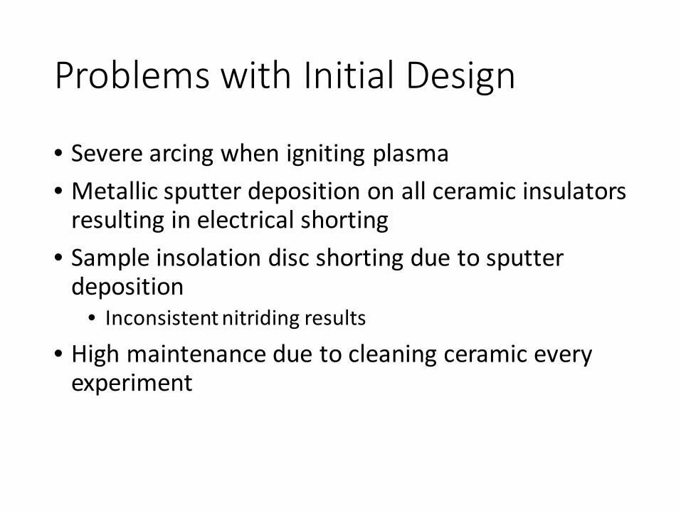
Problems with Initial Design
• Severe arcing when igniting plasma• Metallic sputter deposition on all ceramic insulators
resulting in electrical shorting• Sample insolation disc shorting due to sputter
deposition• Inconsistent nitriding results
• High maintenance due to cleaning ceramic every experiment
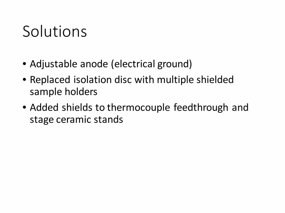
Solutions
• Adjustable anode (electrical ground)• Replaced isolation disc with multiple shielded
sample holders• Added shields to thermocouple feedthrough and
stage ceramic stands
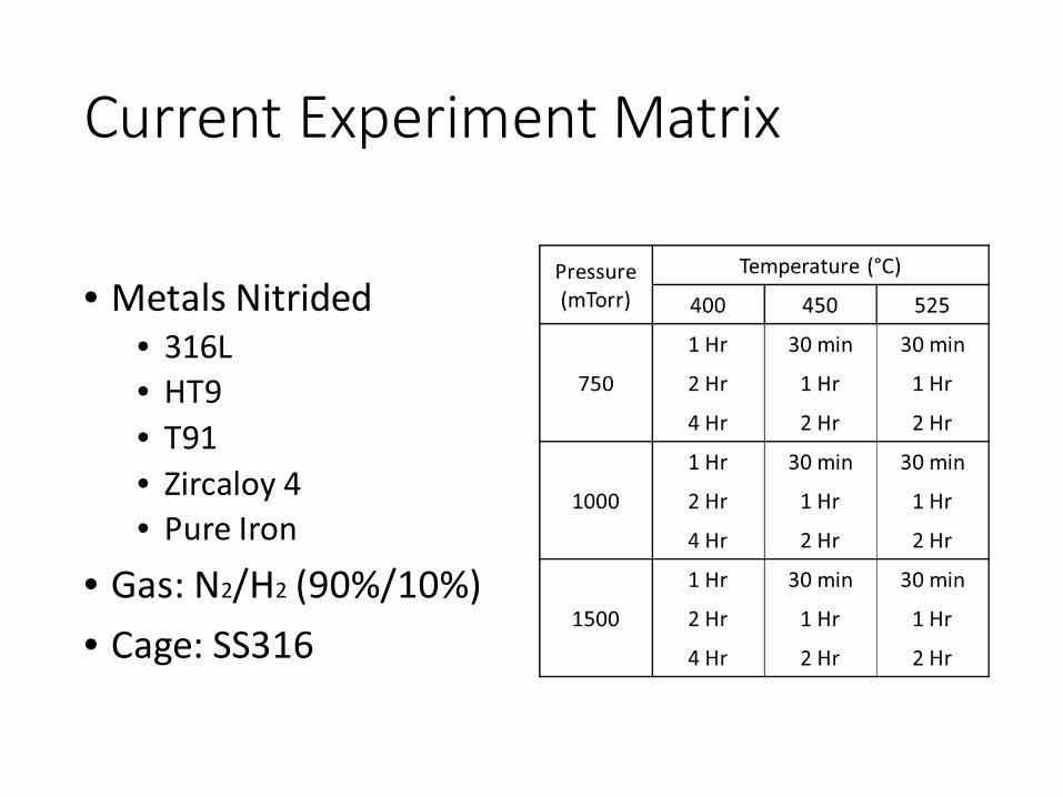
Current Experiment Matrix
• Metals Nitrided • 316L• HT9 • T91• Zircaloy 4• Pure Iron
• Gas: N2/H2 (90%/10%)• Cage: SS316
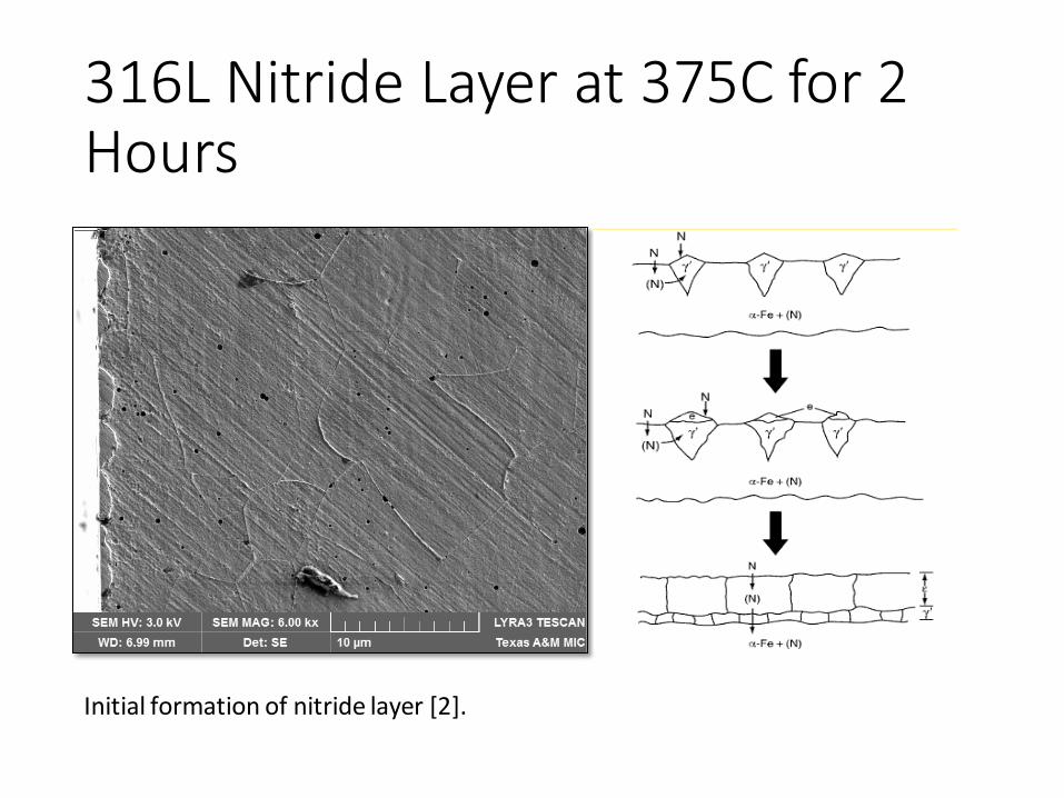
316L Nitride Layer at 375C for 2 Hours
Initial formation of nitride layer [2].
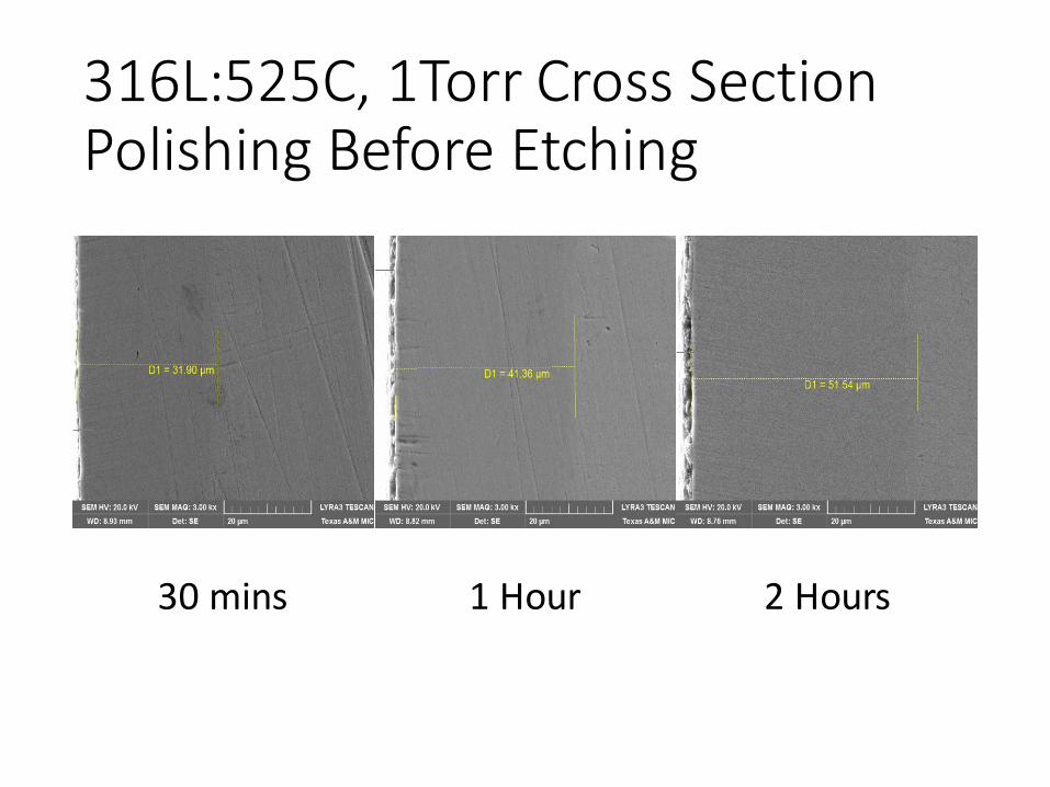
316L:525C, 1Torr Cross Section Polishing Before Etching
30 mins 1 Hour 2 Hours
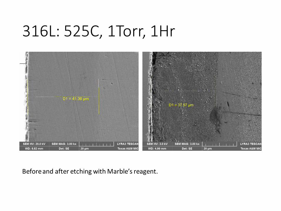
316L: 525C, 1Torr, 1Hr
Before and after etching with Marble’s reagent.
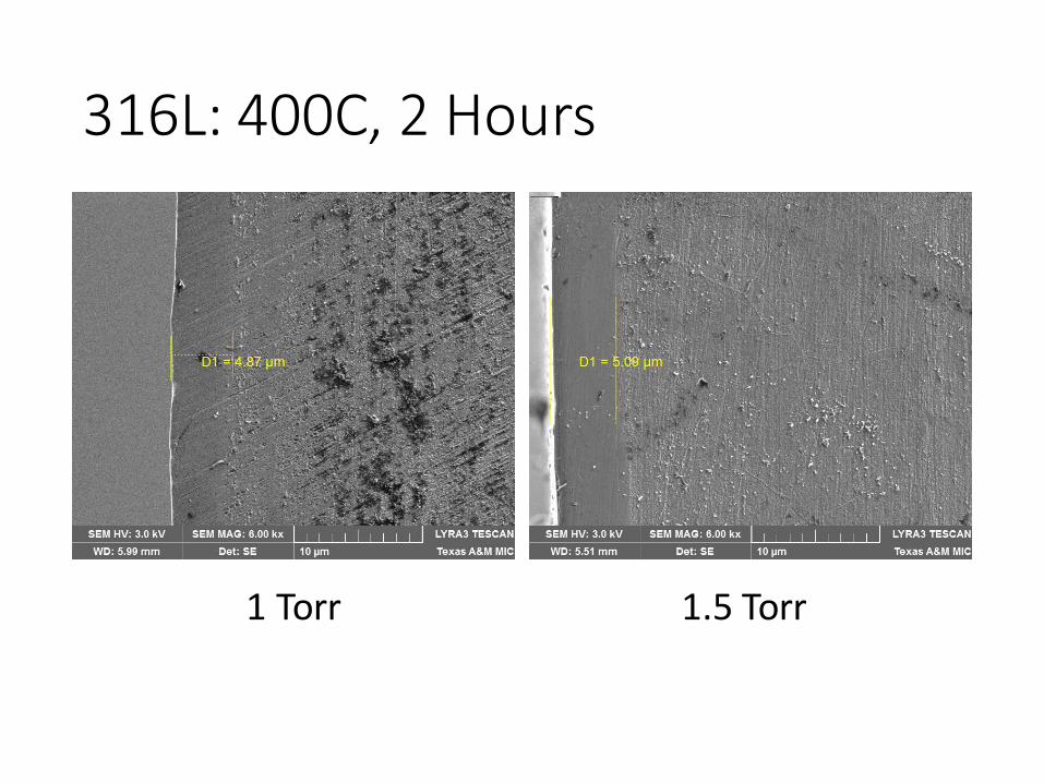
316L: 400C, 2 Hours
1 Torr 1.5 Torr
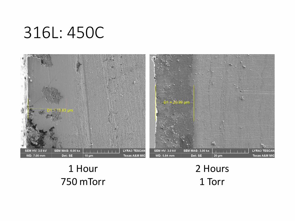
316L: 450C
1 Hour750 mTorr
2 Hours1 Torr
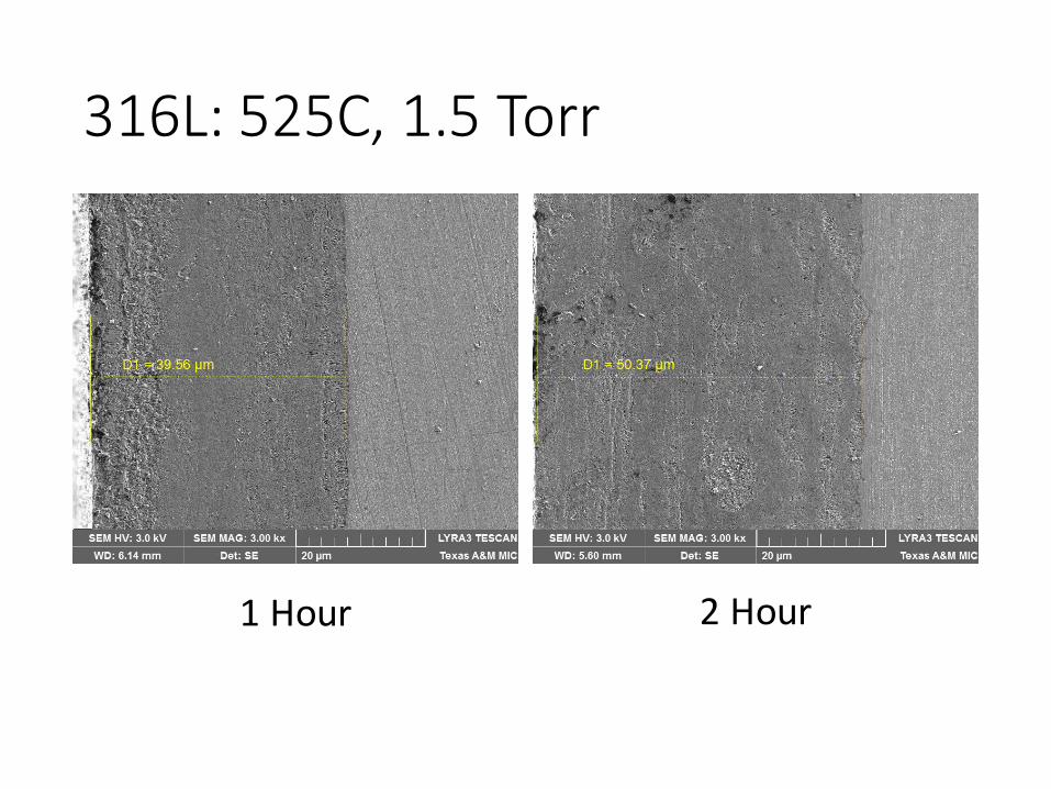
316L: 525C, 1.5 Torr
1 Hour 2 Hour
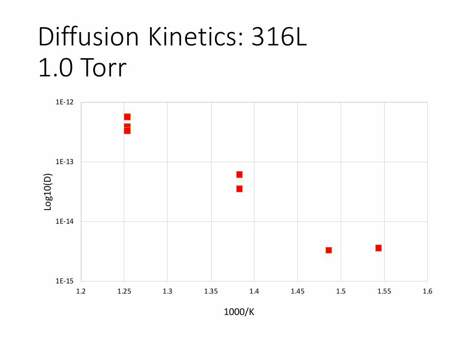
Diffusion Kinetics: 316L1.0 Torr
1E-15
1E-14
1E-13
1E-12
1.2 1.25 1.3 1.35 1.4 1.45 1.5 1.55 1.6
Log1
0(D)
1000/K
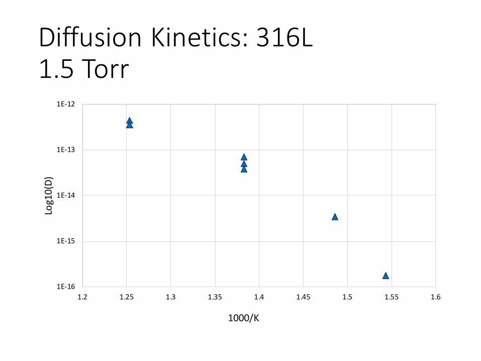
Diffusion Kinetics: 316L1.5 Torr
1E-16
1E-15
1E-14
1E-13
1E-12
1.2 1.25 1.3 1.35 1.4 1.45 1.5 1.55 1.6
Log1
0(D)
1000/K
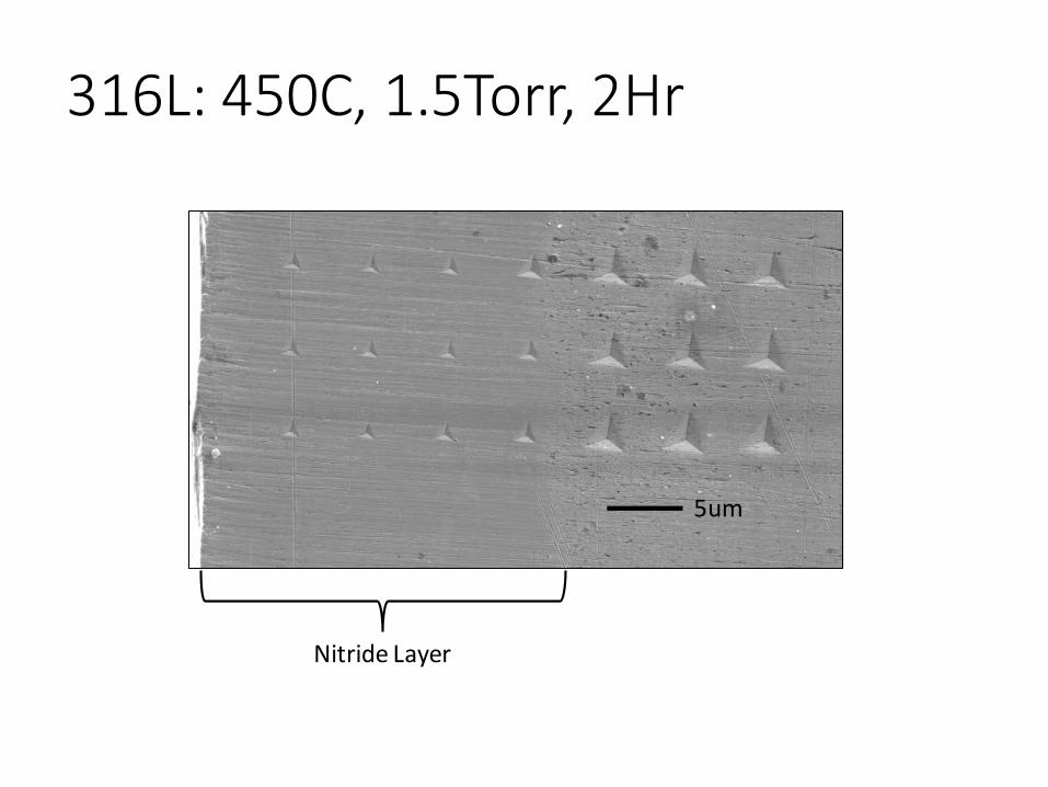
316L: 450C, 1.5Torr, 2Hr
Nitride Layer
5um
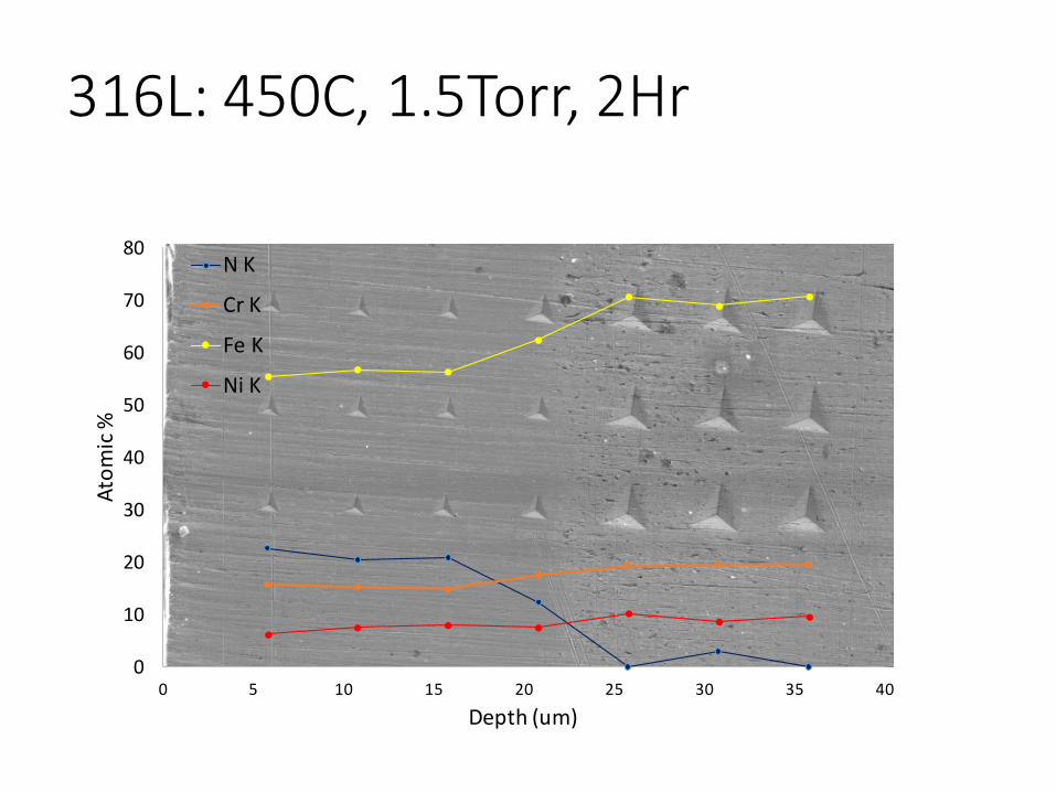
316L: 450C, 1.5Torr, 2Hr
0
10
20
30
40
50
60
70
80
0 5 10 15 20 25 30 35 40
Atom
ic %
Depth (um)
N K
Cr K
Fe K
Ni K
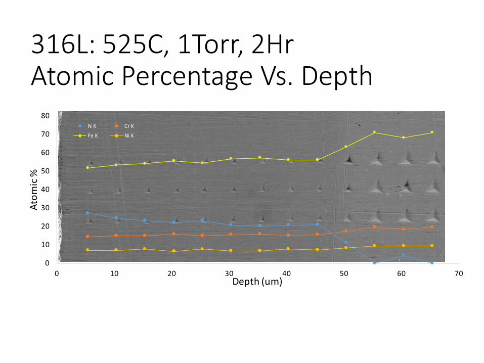
0
10
20
30
40
50
60
70
80
0 10 20 30 40 50 60 70
Atom
ic %
Depth (um)
N K Cr K
Fe K Ni K
316L: 525C, 1Torr, 2HrAtomic Percentage Vs. Depth
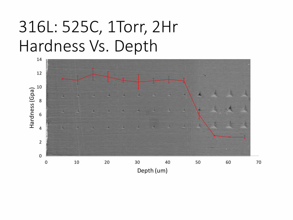
316L: 525C, 1Torr, 2HrHardness Vs. Depth
0
2
4
6
8
10
12
14
0 10 20 30 40 50 60 70
Hard
ness
(Gpa
)
Depth (um)
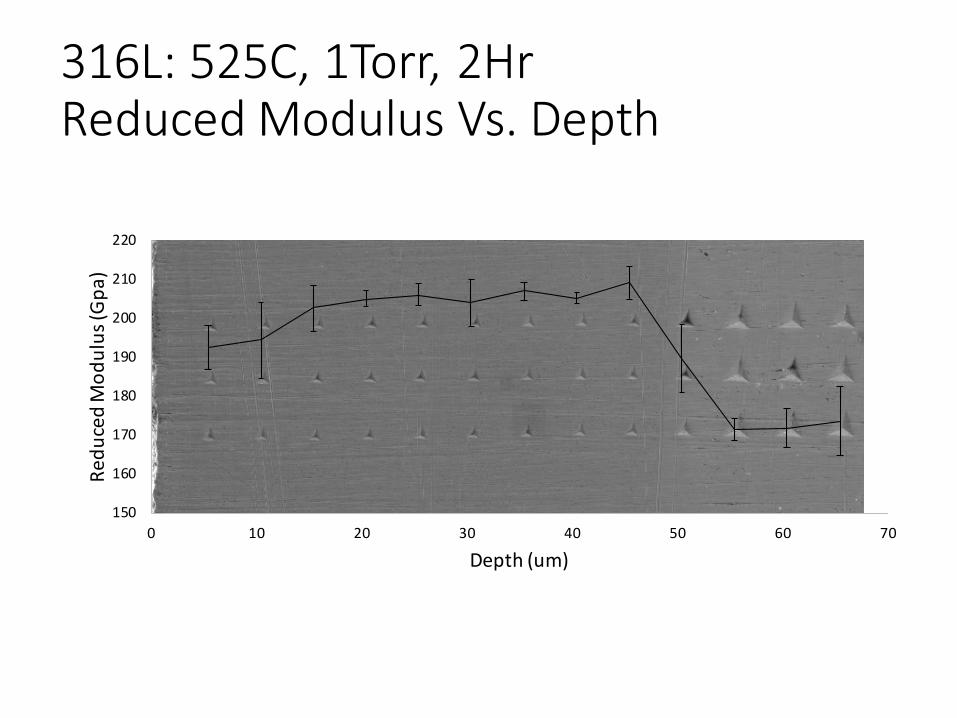
316L: 525C, 1Torr, 2HrReduced Modulus Vs. Depth
150
160
170
180
190
200
210
220
0 10 20 30 40 50 60 70
Redu
ced
Mod
ulus
(Gpa
)
Depth (um)
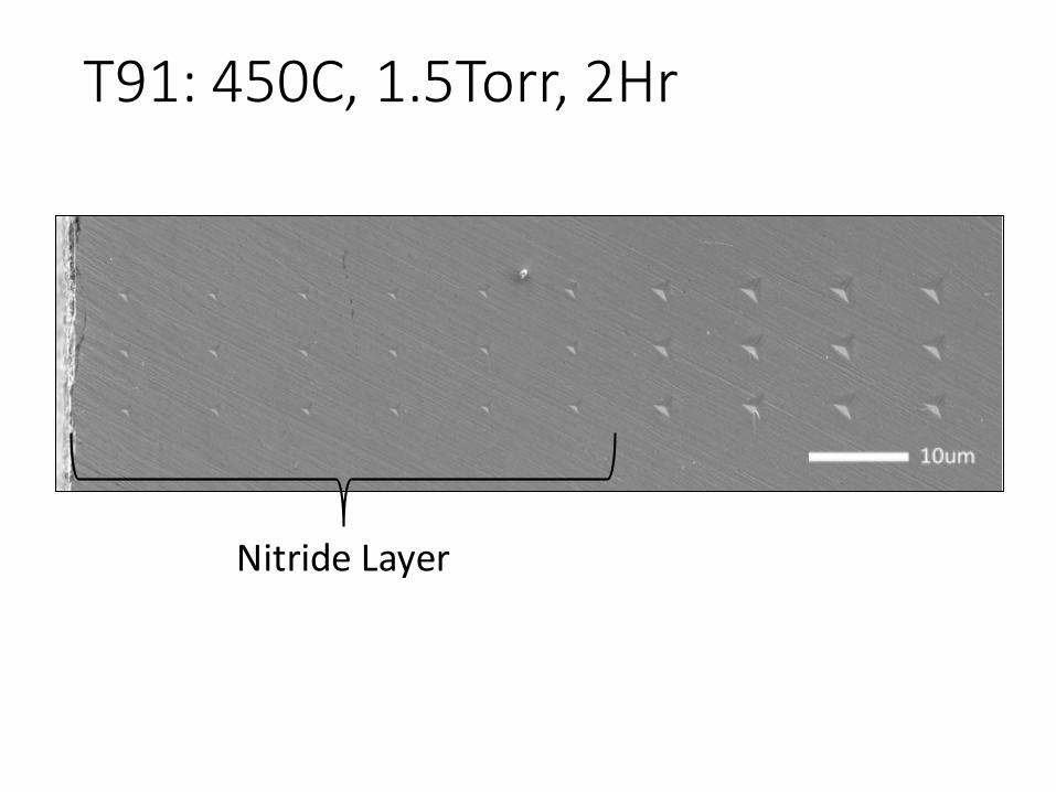
T91: 450C, 1.5Torr, 2Hr
Nitride Layer
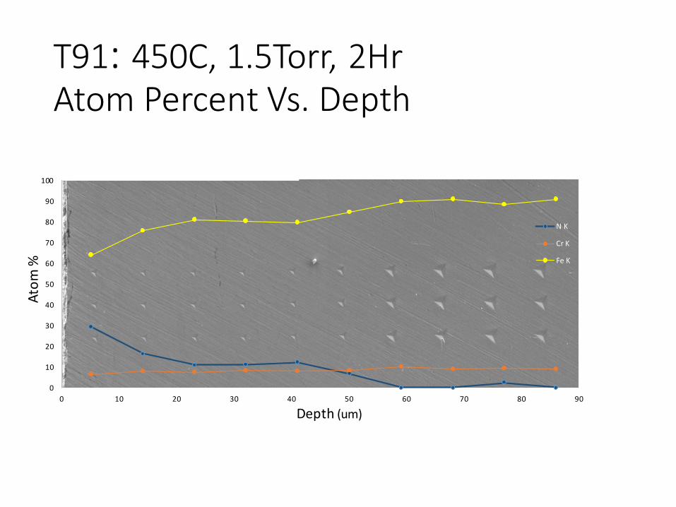
T91: 450C, 1.5Torr, 2HrAtom Percent Vs. Depth
0
10
20
30
40
50
60
70
80
90
100
0 10 20 30 40 50 60 70 80 90
Atom
%
Depth (um)
N K
Cr K
Fe K
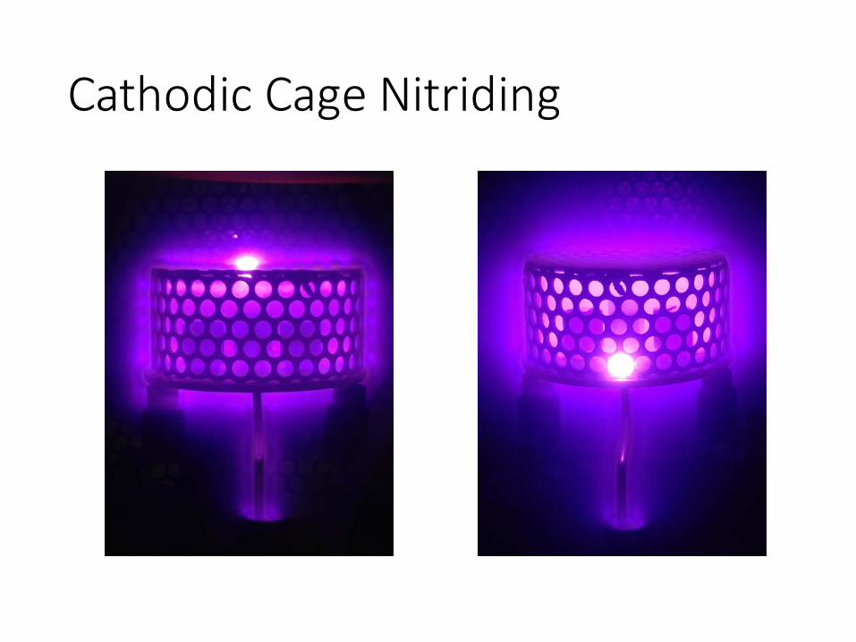
Cathodic Cage Nitriding
Future Work
• Analyze nitrided HT9, Zircaloy4, T91, Pure Iron, Pure Zirconium
• Measure how cage thickness changes Hollow Cathode Effect
Questions?
1) R.R.M. de Sousa, et al., Cathodic cage plasma nitriding of austenitic stainless steel
(AISI 316): influence of the working pressure on the nitrided layers properties, Mater.
Res., 17 (2014), pp. 427–433
2) Pye, D., Practical Nitriding and Ferritic Nitrocarburizing. 2003, Materials Park, OH:
ASM International. 256.
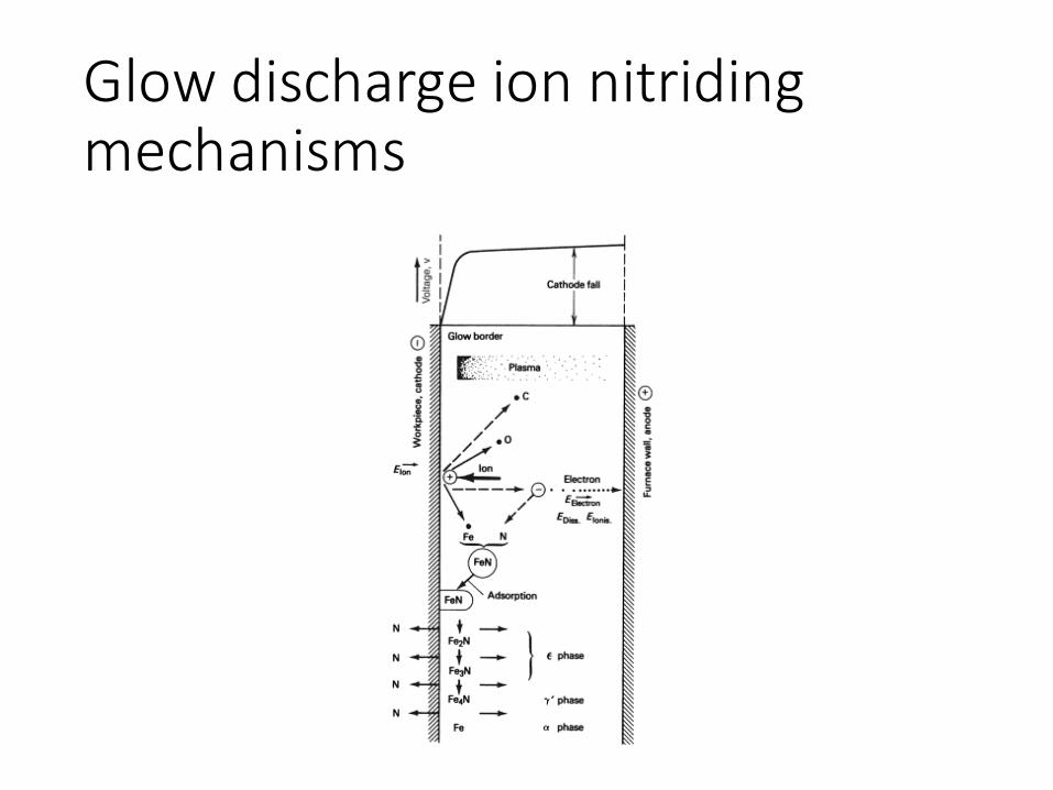
Glow discharge ion nitriding mechanisms
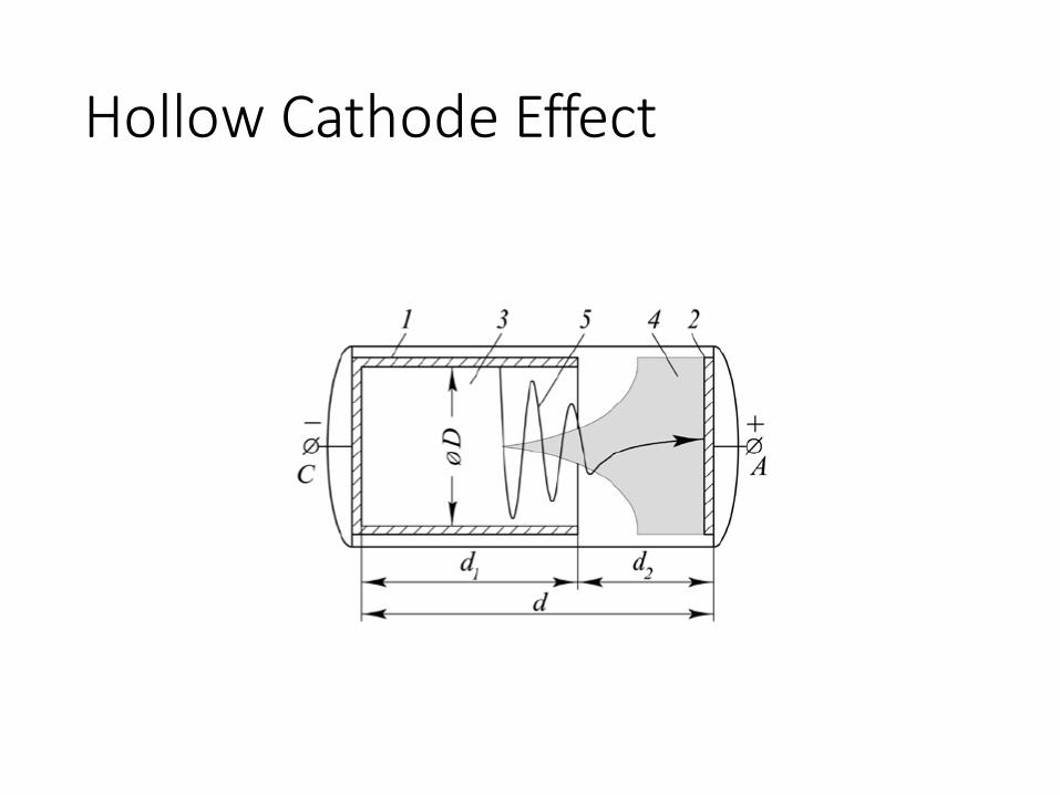
Hollow Cathode Effect