Embed Size (px)
Citation preview

PREPARED BY
MRS.PRAVEENA RAO
ASSISTANT PROFESSOR
DEPARTMENT OF CIVIL ENGINEERING, IARE
ADVANCED STEEL DESIGN
M.TECH- STRUCTURAL
ENGINEERING
SIMPLE CONNECTION – RIVETED,
BOLTED PINNED & WELDED
CONNECTION
UNIT 1

Connections and Tension Member Design
Connections
Connections must be able to transfer any axial force, shear, or moment from member to member or from beam to column.
Steel construction accomplishes this with bolt and welds. Wood construction uses nails, bolts, shear plates, and split-ring
connectors.
Bolted and Welded Connections
The limit state for connections depends on the loads:
1. tension yielding
2. shear yielding
3. bearing yielding
4. bending yielding due to eccentric loads
5. rupture
Welds must resist tension AND shear stress. The design strengths depend on
the weld materials.
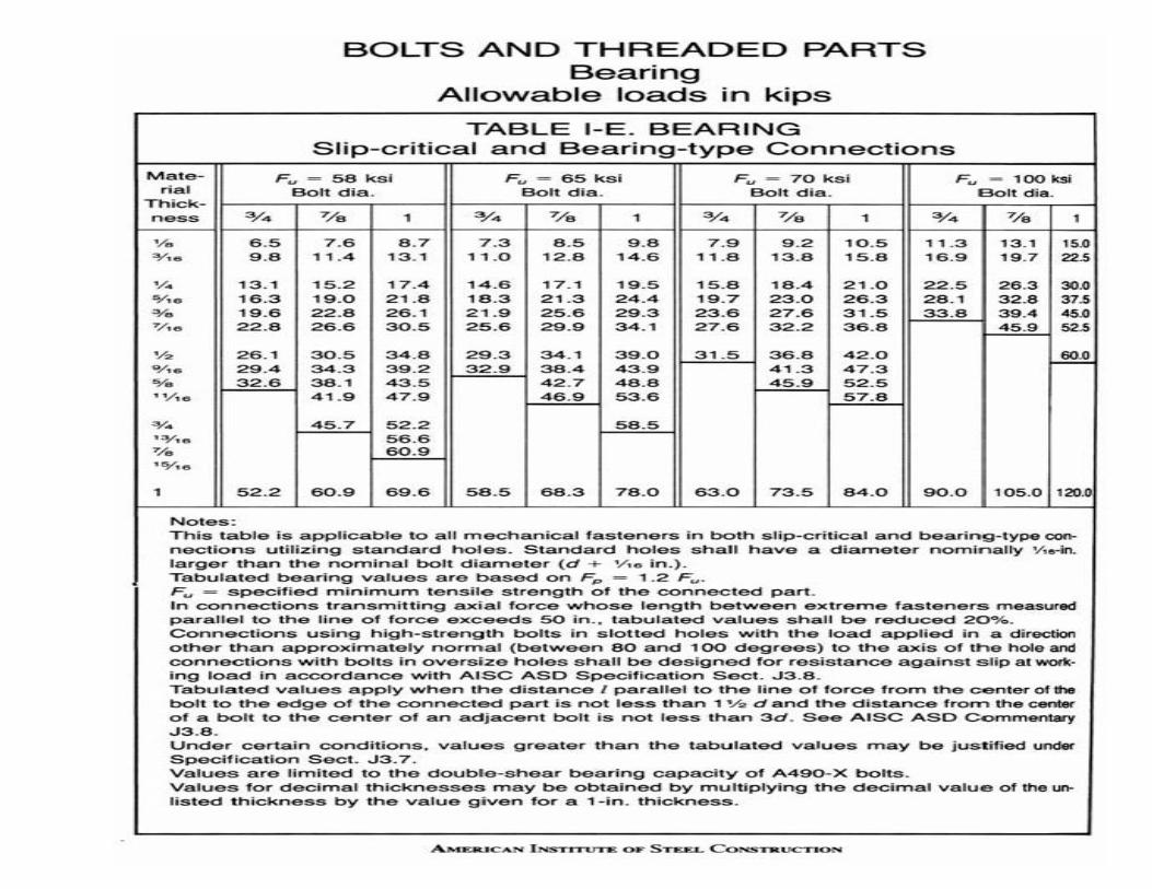
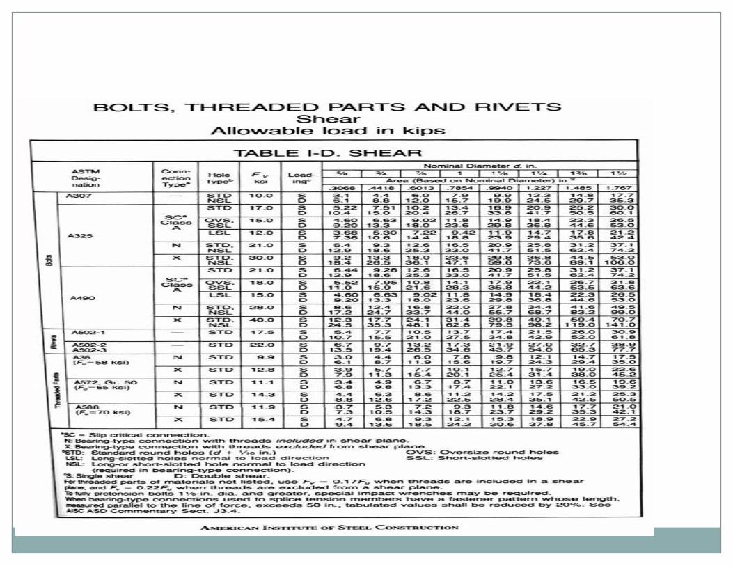
Bolted Connection Design
Bolt designations signify material and type of connection where SC: slip criticalN: bearing-type connection with bolt threads included in shear plane
X: bearing-type connection with bolt threads excluded from shear plane
Bolts rarely fail in bearing. The material with the hole will more likely yield first. Standard bolt holes are
1/16” larger than the bolt diameter.
3
4
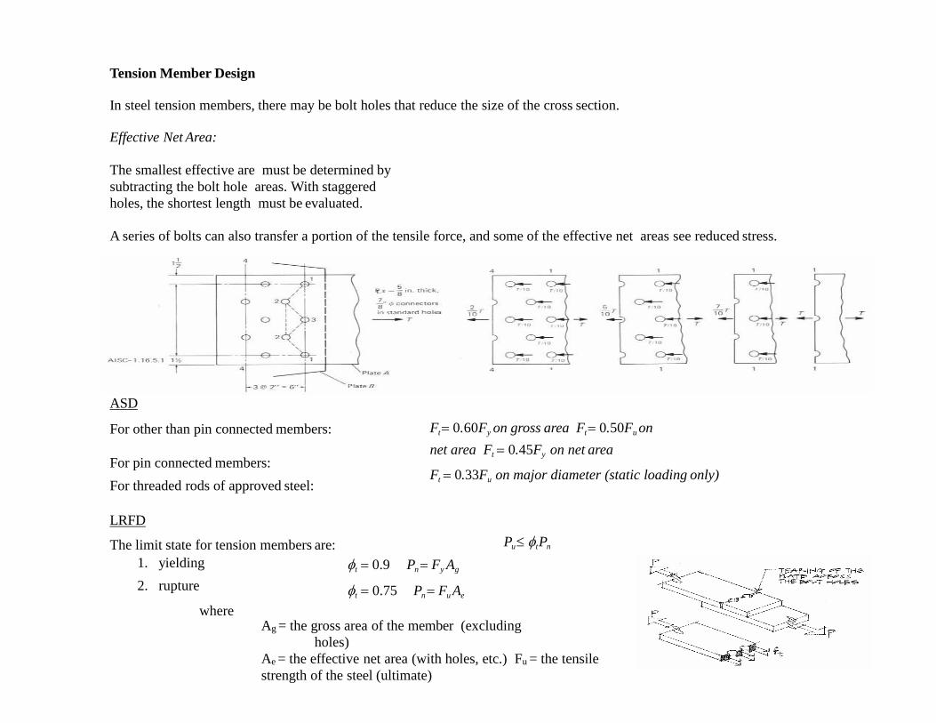
Tension Member Design
In steel tension members, there may be bolt holes that reduce the size of the cross section.
Effective Net Area:
The smallest effective are must be determined by
subtracting the bolt hole areas. With staggered
holes, the shortest length must be evaluated.
A series of bolts can also transfer a portion of the tensile force, and some of the effective net areas see reduced stress.
ASD
For other than pin connected members:
For pin connected members:
For threaded rods of approved steel:
Ft 0.60Fy on gross area Ft 0.50Fu on
net area Ft 0.45Fy on net area
Ft 0.33Fu on major diameter (static loading only)
LRFD
The limit state for tension members are:
1. yielding
2. rupture
where
Pu tPn
t 0.9 Pn Fy Ag
t 0.75 Pn Fu Ae
Ag = the gross area of the member (excluding
holes)
Ae = the effective net area (with holes, etc.) Fu = the tensile
strength of the steel (ultimate)6
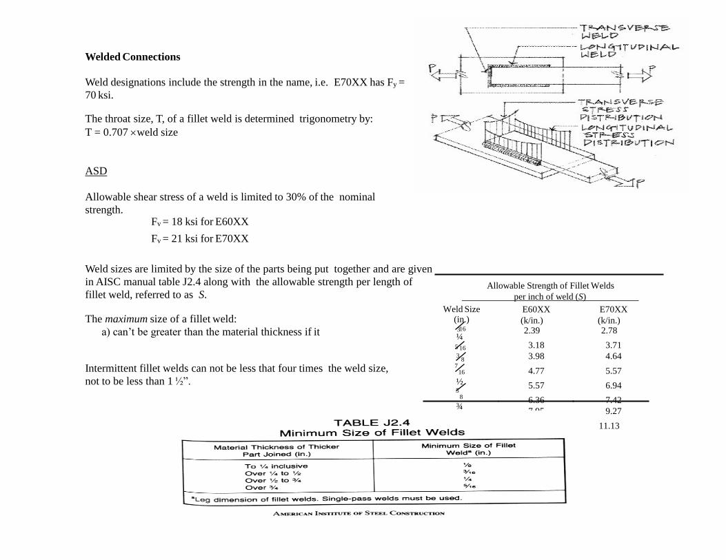
Welded Connections
Weld designations include the strength in the name, i.e. E70XX has Fy =
70 ksi.
The throat size, T, of a fillet weld is determined trigonometry by:
T = 0.707 weld size
ASD
Allowable shear stress of a weld is limited to 30% of the nominal
strength.Fv = 18 ksi for E60XX
Fv = 21 ksi for E70XX
Weld sizes are limited by the size of the parts being put together and are given
in AISC manual table J2.4 along with the allowable strength per length of
fillet weld, referred to as S.
The maximum size of a fillet weld:
a) can’t be greater than the material thickness if it
Intermittent fillet welds can not be less that four times the weld size,
not to be less than 1 ½”.
Allowable Strength of Fillet Welds
per inch of weld (S)
16
Weld Size (in.)3
16
¼5
83
716
½5
8
¾
E60XX
(k/in.) 2.39
3.18
3.98
4.77
5.57
6.36
7.95
9.55
E70XX
(k/in.) 2.78
3.71
4.64
5.57
6.94
7.42
9.27
11.13
7
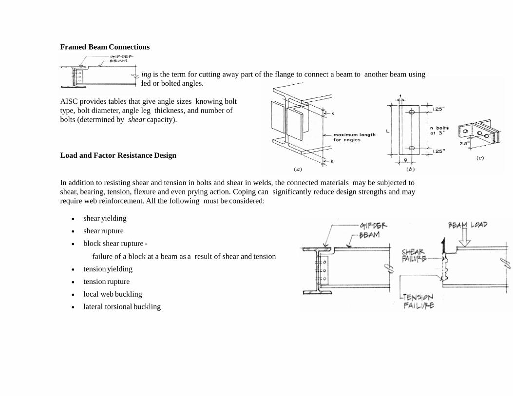
Framed Beam Connections
Coping is the term for cutting away part of the flange to connect a beam to another beam using
welded or bolted angles.
AISC provides tables that give angle sizes knowing bolt
type, bolt diameter, angle leg thickness, and number of
bolts (determined by shear capacity).
Load and Factor Resistance Design
In addition to resisting shear and tension in bolts and shear in welds, the connected materials may be subjected to
shear, bearing, tension, flexure and even prying action. Coping can significantly reduce design strengths and may
require web reinforcement. All the following must be considered:
shear yielding
shear rupture
block shear rupture -
failure of a block at a beam as a result of shear and tension
tension yielding
tension rupture
local web buckling
lateral torsional buckling
8
9
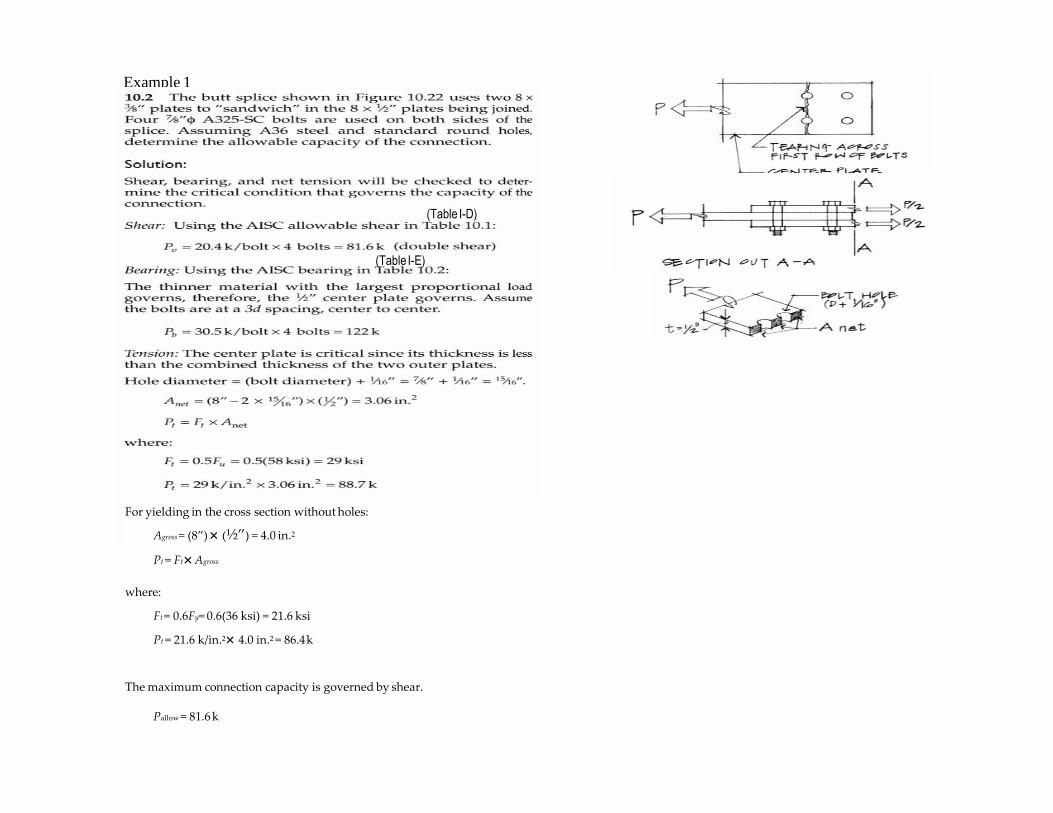
Example 1
(Table I-D)
(Table I-E)
For yielding in the cross section without holes:
Agross = (8”) (½”) = 4.0 in.2
Pt = Ft Agross
where:
Ft = 0.6Fy= 0.6(36 ksi) = 21.6 ksi
Pt = 21.6 k/in.2 4.0 in.2 = 86.4k
The maximum connection capacity is governed by shear.
Pallow = 81.6 k
11
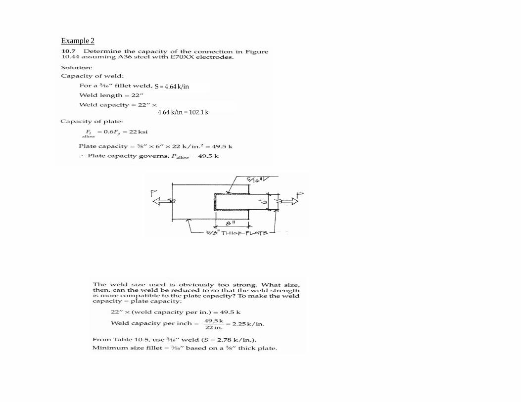
Example 2
S = 4.64 k/in
4.64 k/in = 102.1 k
12
Example 3
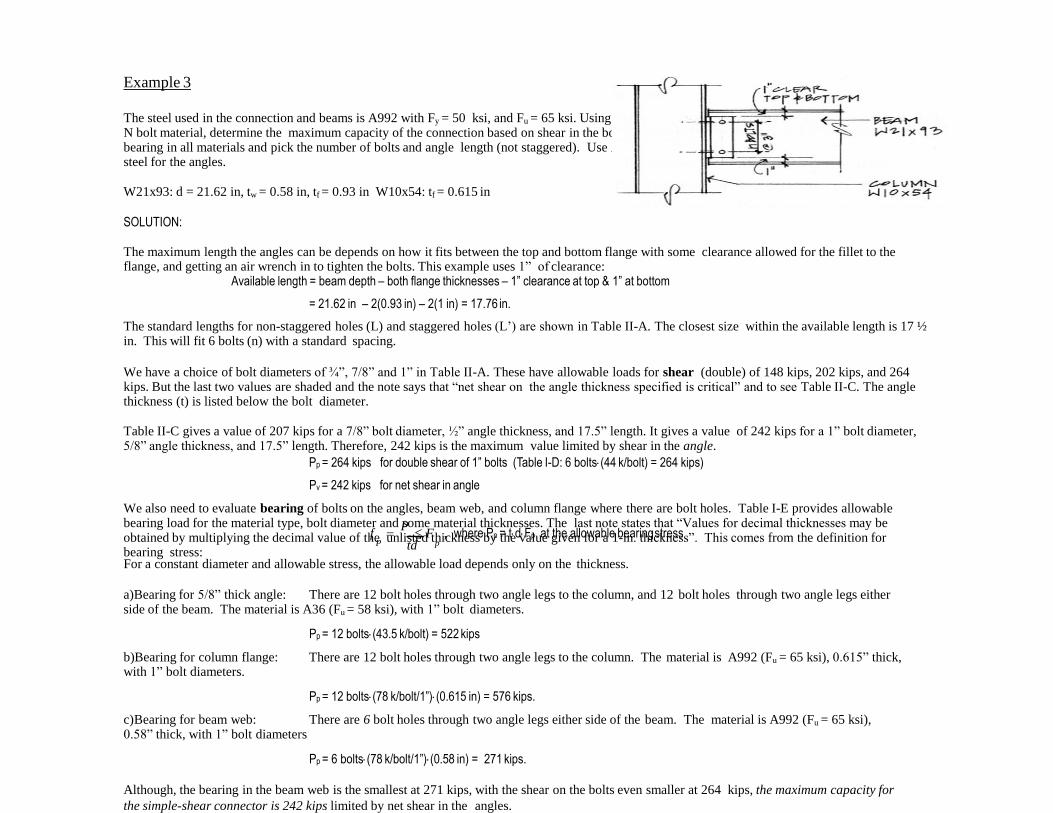
The steel used in the connection and beams is A992 with Fy = 50 ksi, and Fu = 65 ksi. Using A490-N bolt material, determine the maximum capacity of the connection based on shear in the bolts, bearing in all materials and pick the number of bolts and angle length (not staggered). Use A36 steel for the angles.
W21x93: d = 21.62 in, tw = 0.58 in, tf = 0.93 in W10x54: tf = 0.615 in
SOLUTION:
The maximum length the angles can be depends on how it fits between the top and bottom flange with some clearance allowed for the fillet to the flange, and getting an air wrench in to tighten the bolts. This example uses 1” of clearance:
Available length = beam depth – both flange thicknesses – 1” clearance at top & 1” at bottom
= 21.62 in – 2(0.93 in) – 2(1 in) = 17.76 in.
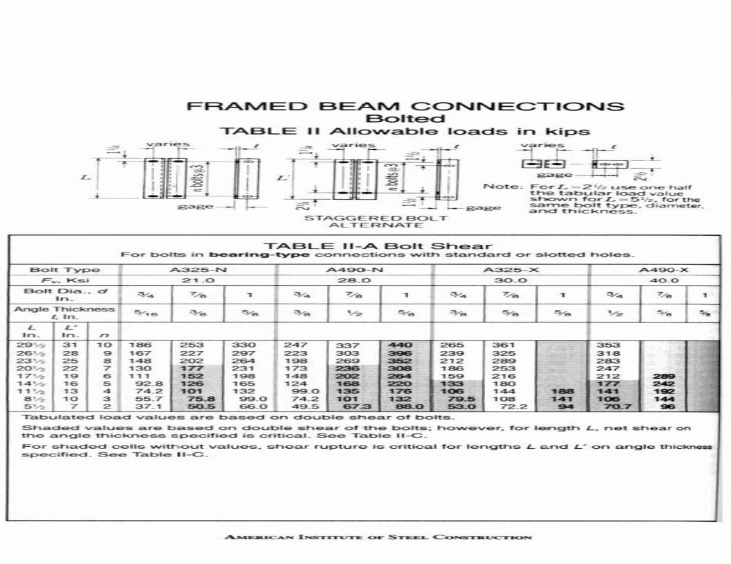
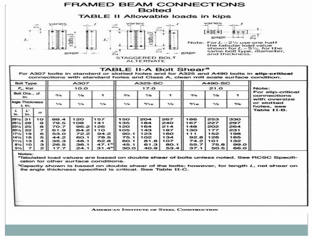
The standard lengths for non-staggered holes (L) and staggered holes (L’) are shown in Table II-A. The closest size within the available length is 17 ½ in. This will fit 6 bolts (n) with a standard spacing.
We have a choice of bolt diameters of ¾”, 7/8” and 1” in Table II-A. These have allowable loads for shear (double) of 148 kips, 202 kips, and 264 kips. But the last two values are shaded and the note says that “net shear on the angle thickness specified is critical” and to see Table II-C. The angle thickness (t) is listed below the bolt diameter.
Table II-C gives a value of 207 kips for a 7/8” bolt diameter, ½” angle thickness, and 17.5” length. It gives a value of 242 kips for a 1” bolt diameter, 5/8” angle thickness, and 17.5” length. Therefore, 242 kips is the maximum value limited by shear in the angle.
Pp = 264 kips for double shear of 1” bolts (Table I-D: 6 bolts(44 k/bolt) = 264 kips)
Pv = 242 kips for net shear in angle
We also need to evaluate bearing of bolts on the angles, beam web, and column flange where there are bolt holes. Table I-E provides allowable bearing load for the material type, bolt diameter and some material thicknesses. The last note states that “Values for decimal thicknesses may be obtained by multiplying the decimal value of the unlisted thickness by the value given for a 1-in. thickness”. This comes from the definition for bearing stress:
tdf
P F , where Pp = tdFp at the allowable bearingstress
P p
For a constant diameter and allowable stress, the allowable load depends only on the thickness.
a)Bearing for 5/8” thick angle: There are 12 bolt holes through two angle legs to the column, and 12 bolt holes through two angle legs either side of the beam. The material is A36 (Fu = 58 ksi), with 1” bolt diameters.
Pp = 12 bolts(43.5 k/bolt) = 522 kips
b)Bearing for column flange: There are 12 bolt holes through two angle legs to the column. The material is A992 (Fu = 65 ksi), 0.615” thick, with 1” bolt diameters.
Pp = 12 bolts(78 k/bolt/1”)(0.615 in) = 576 kips.
c)Bearing for beam web: There are 6 bolt holes through two angle legs either side of the beam. The material is A992 (Fu = 65 ksi), 0.58” thick, with 1” bolt diameters
Pp = 6 bolts(78 k/bolt/1”)(0.58 in) = 271 kips.
Although, the bearing in the beam web is the smallest at 271 kips, with the shear on the bolts even smaller at 264 kips, the maximum capacity for
the simple-shear connector is 242 kips limited by net shear in the angles.
14
UNIT II
Eccentric and moment Connections
Instructional Objectives:
At the end of this lesson, the students should be able to understand:
Meaning of eccentricity in loading.
Procedure for designing a screw/bolted joint in eccentric loading.
Procedure for designing riveted joint under eccentric loading.
In many applications, a machine member is subjected to load such that a bending moment is developed in
addition to direct normal or shear loading. Such type of loading is commonly known as eccentric loading.
(i)
(ii)
(iii)
Screw joint
Riveted joint
Welded joint
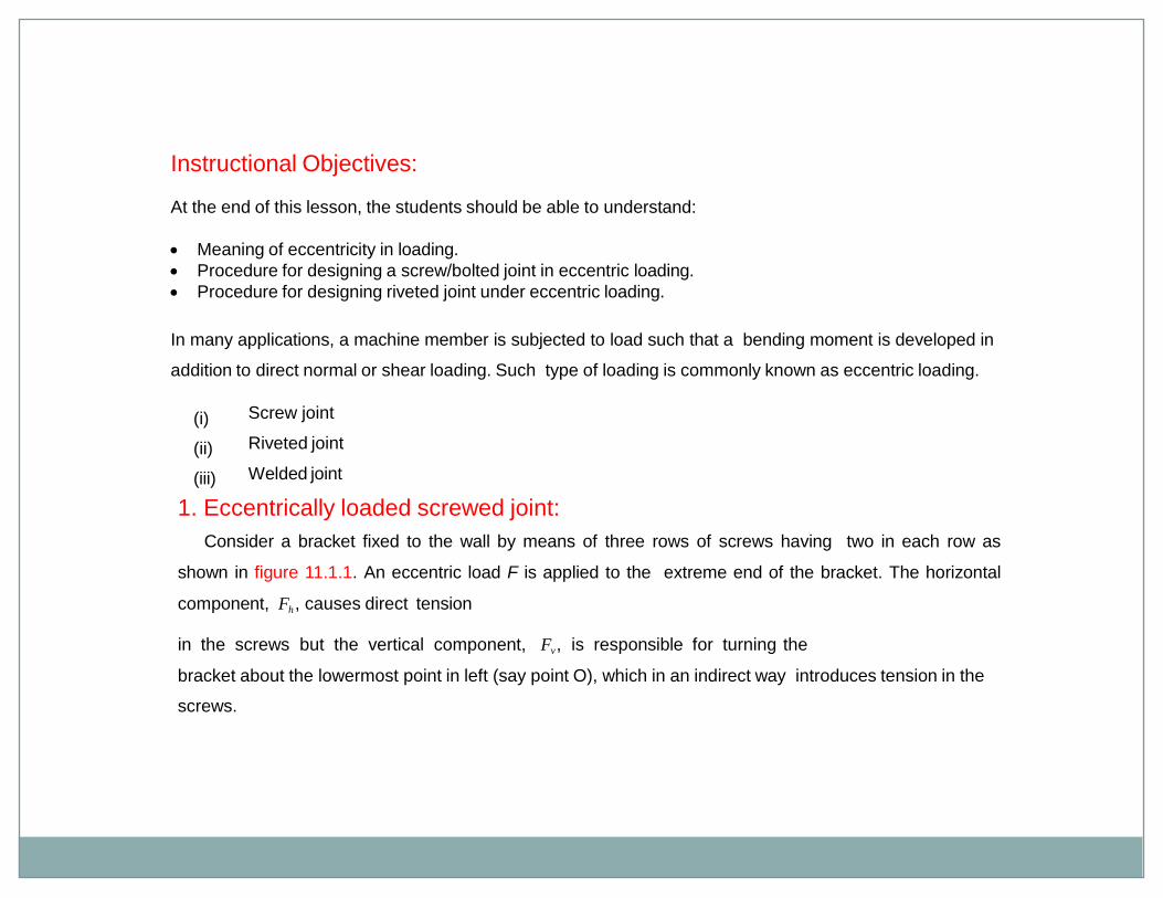
1. Eccentrically loaded screwed joint:
Consider a bracket fixed to the wall by means of three rows of screws having two in each row as
shown in figure 11.1.1. An eccentric load F is applied to the extreme end of the bracket. The horizontal
component, Fh, causes direct tension
in the screws but the vertical component, Fv , is responsible for turning the
bracket about the lowermost point in left (say point O), which in an indirect way introduces tension in the
screws.
Fv
FH
L
Figure 11.1.1: Eccentrically loaded bolted joint
It is easy to note that the tension in the screws cannot be obtained by equations of statics alone.
Hence, additional equations must be formed to solve for the unknowns for this statically indeterminate
problem. Since there is a tendency for the bracket to rotate about point O then, assuming the bracket to
be rigid, the following equations are easily obtained.
tan y1
y2 y3
l1 l2 l3
where yi =elongation of the i-th bolt
li =distance of the axis of the i-th bolt from point O.
If the bolts are made of same material and have same dimension, then
fi kyi
where fi =force in the i-th bolt
k =stiffness of the bolts
Thus fi li or fi li ( =proportionalityconstant)
i2 l2
in a row.
Thus the force in the i-th screw is
F hii
F L F Lf
i l2
h 1 v 2
2l , where n = total number of bolts.
n
t
where st =allowable tensile stress of the bolt.
Note that Fv causes also direct shear in the bolt. Its effect may be ignored for a preliminary design
calculation.
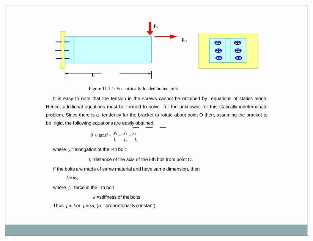
fi
Fv
FHL2li
yi
L1
Figure 11.1.2: Determination of forces in bolts
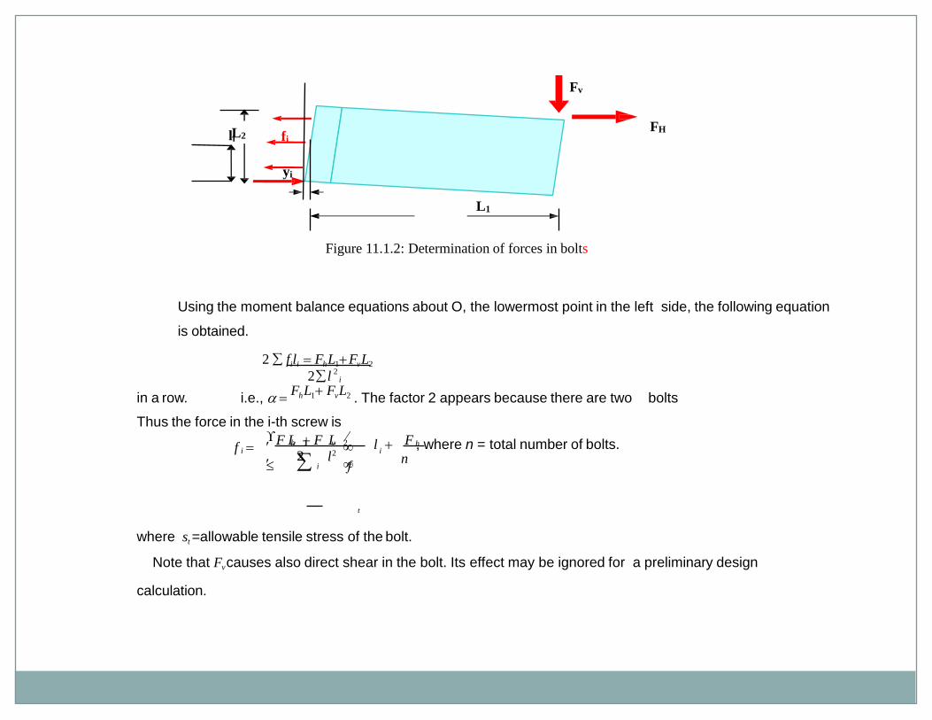
Using the moment balance equations about O, the lowermost point in the left side, the following equation
is obtained.
2 fili Fh L1 Fv L2
i.e., Fh L1 Fv L2 . The factor 2 appears because there are two bolts
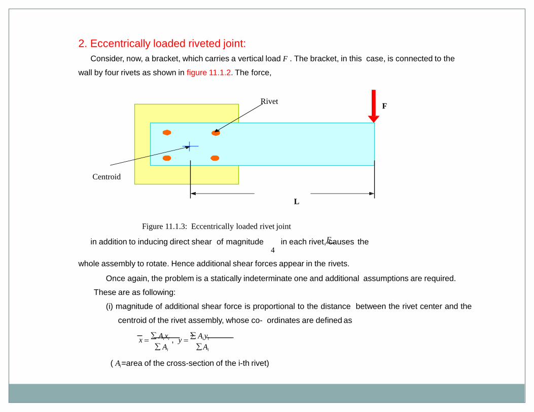
2. Eccentrically loaded riveted joint:
Consider, now, a bracket, which carries a vertical load F . The bracket, in this case, is connected to the
wall by four rivets as shown in figure 11.1.2. The force,
Fin addition to inducing direct shear of magnitude in each rivet, causes the4
whole assembly to rotate. Hence additional shear forces appear in the rivets.
FRivet
Centroid
L
Figure 11.1.3: Eccentrically loaded rivet joint
Once again, the problem is a statically indeterminate one and additional assumptions are required.
These are as following:
(i) magnitude of additional shear force is proportional to the distance between the rivet center and the
centroid of the rivet assembly, whose co- ordinates are defined as
x Ai xi , y
Aiyi
Ai Ai
( Ai =area of the cross-section of the i-th rivet)
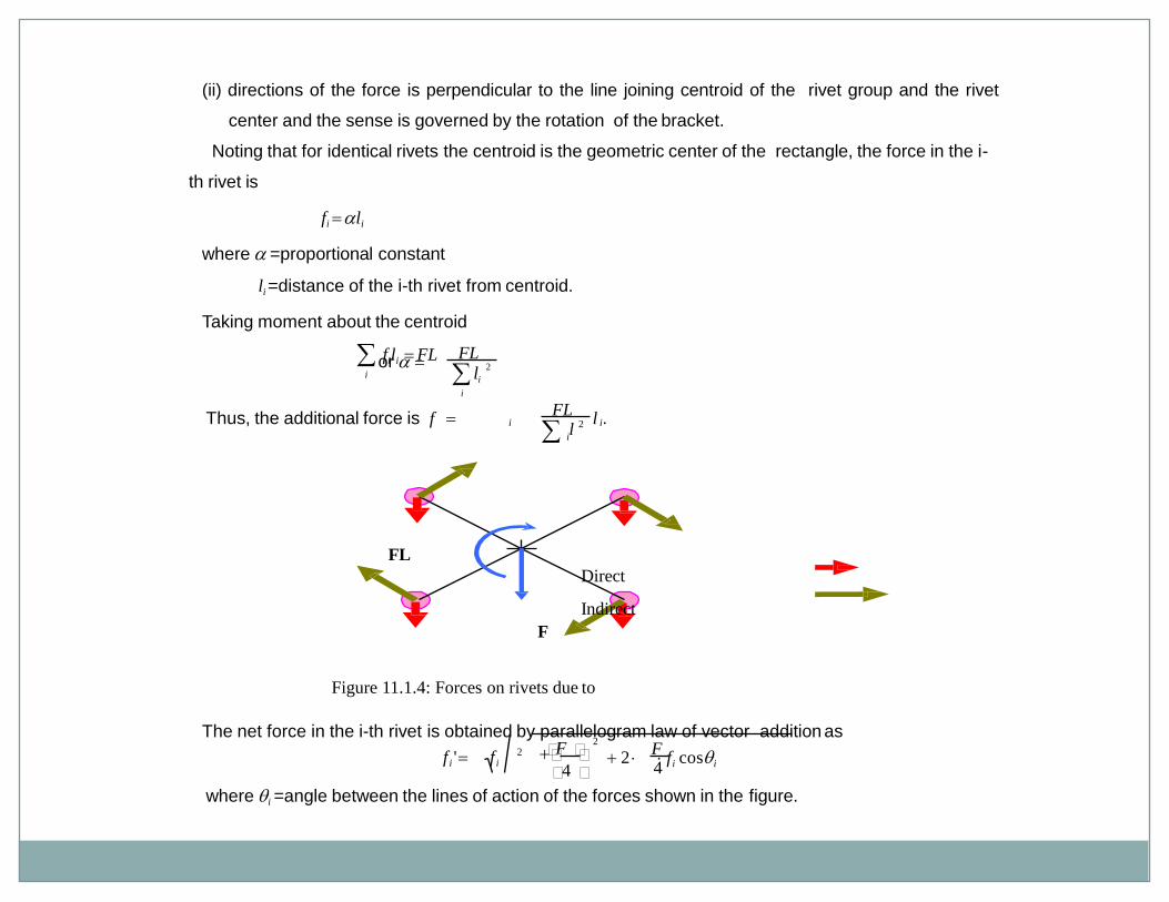
(ii) directions of the force is perpendicular to the line joining centroid of the rivet group and the rivet
center and the sense is governed by the rotation of the bracket.
Noting that for identical rivets the centroid is the geometric center of the rectangle, the force in the i-
th rivet is
fi li
where =proportional constant
li =distance of the i-th rivet from centroid.
Taking moment about the centroid
fili FLi
2
FLor
li
i
iil
FL
i
Thus, the additional force is f 2 l .
FL
Direct
Indirect
F
Figure 11.1.4: Forces on rivets due to
The net force in the i-th rivet is obtained by parallelogram law of vector addition asF4
22 2 fi cosi
F 4
f i ' f i
where i =angle between the lines of action of the forces shown in the figure.
For safe designing we must have
max fi ' sA s
where ss =allowable shear stress of the rivet.
Model questions and answers:
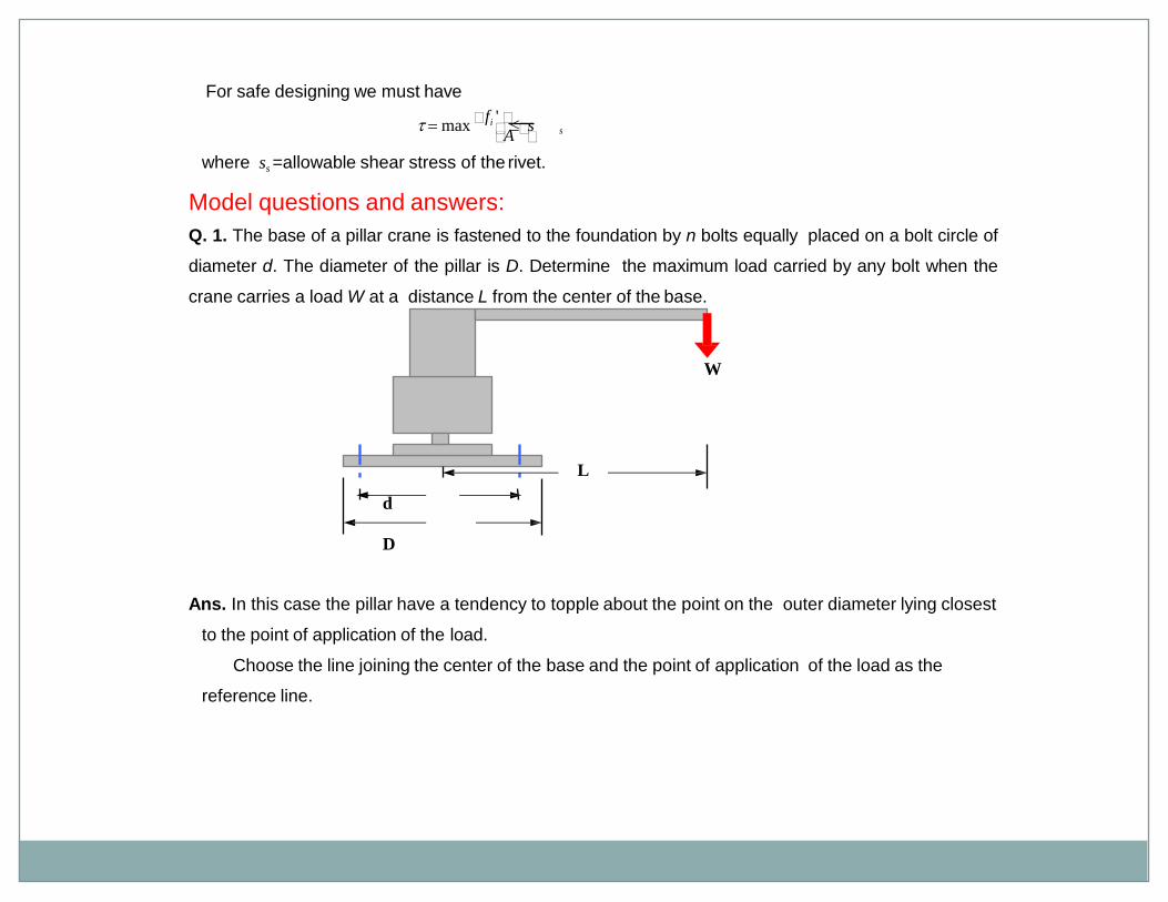
Q. 1. The base of a pillar crane is fastened to the foundation by n bolts equally placed on a bolt circle of
diameter d. The diameter of the pillar is D. Determine the maximum load carried by any bolt when the
crane carries a load W at a distance L from the center of the base.
W
L
d
D
Ans. In this case the pillar have a tendency to topple about the point on the outer diameter lying closest
to the point of application of the load.
Choose the line joining the center of the base and the point of application of the load as the
reference line.
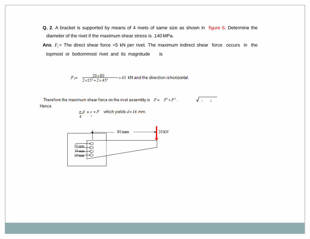
Q. 2. A bracket is supported by means of 4 rivets of same size as shown in figure 6. Determine the
diameter of the rivet if the maximum shear stress is 140 MPa.
Ans. F1 = The direct shear force =5 kN per rivet. The maximum indirect shear force occurs in the
topmost or bottommost rivet and its magnitude is
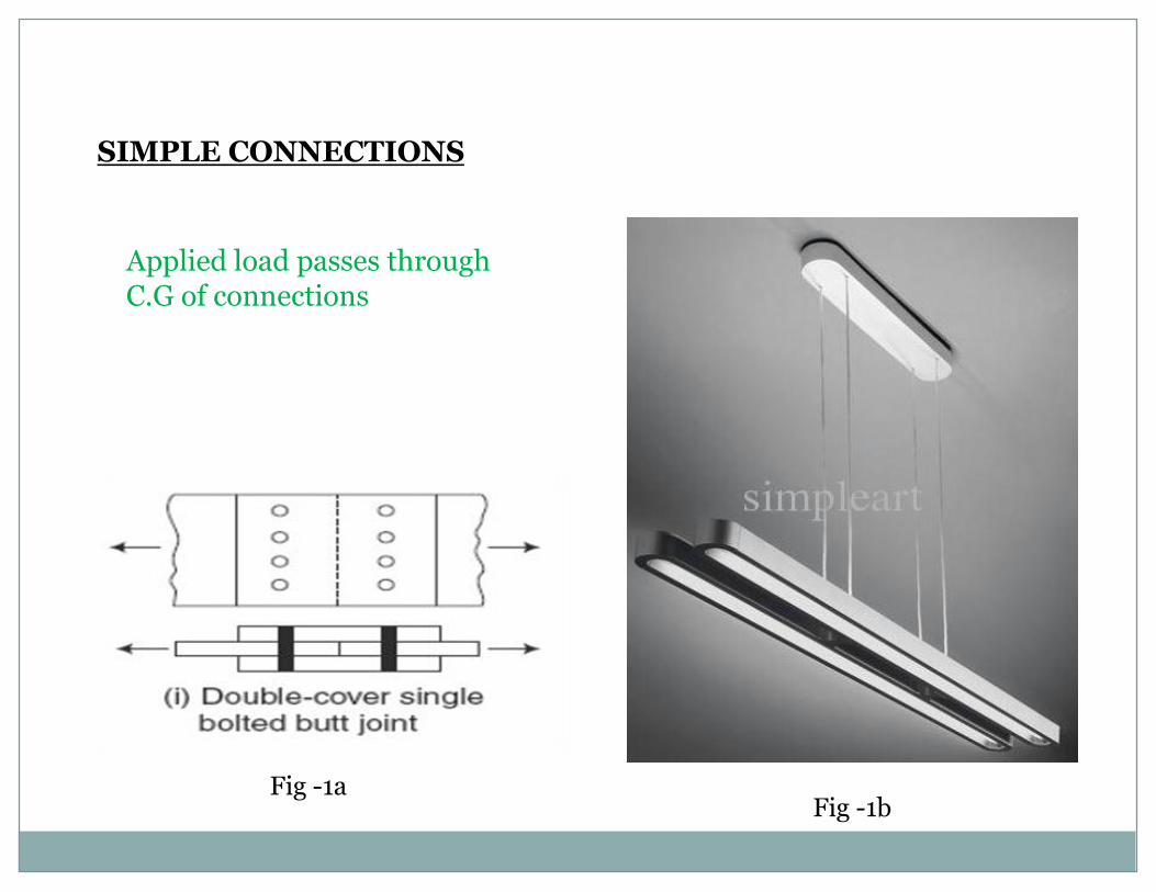
SIMPLE CONNECTIONS
Fig -1aFig -1b
Applied load passes through C.G of connections
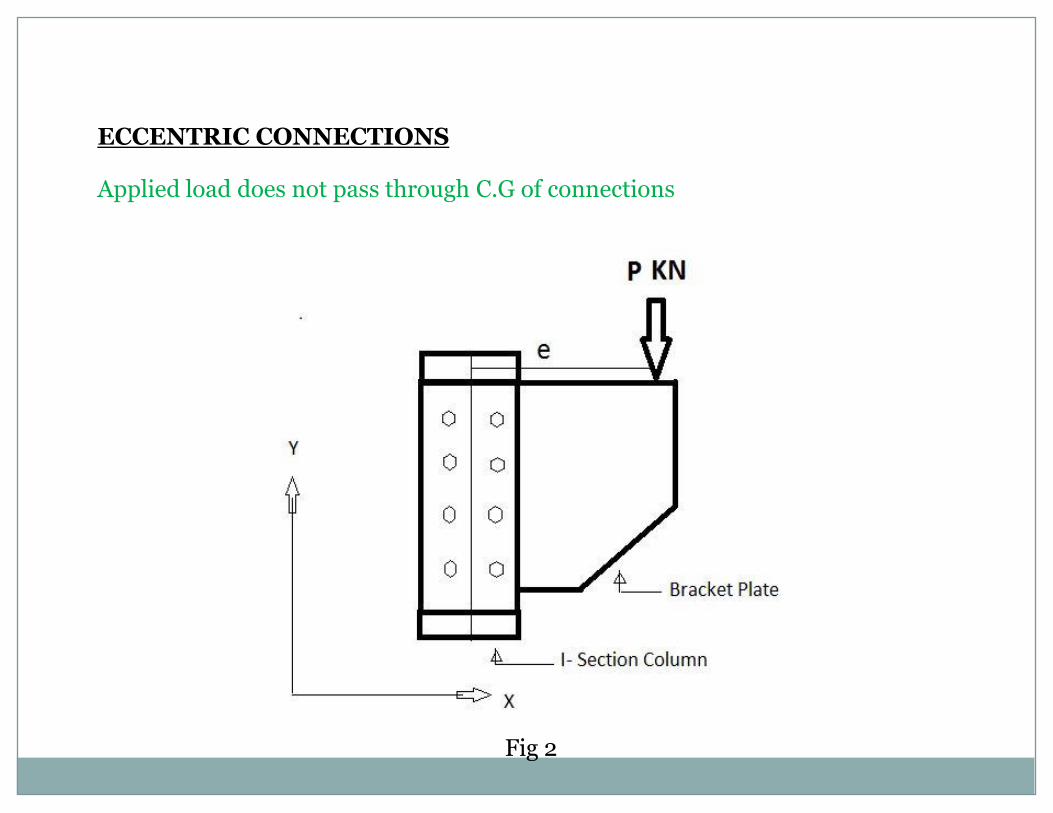
ECCENTRIC CONNECTIONS
Applied load does not pass through C.G of connections
Fig 2

CONNECTIONS SUBJECTED TO ECCENTRIC SHEAR
Seat Connections
Framed Connections
Bracket Connections
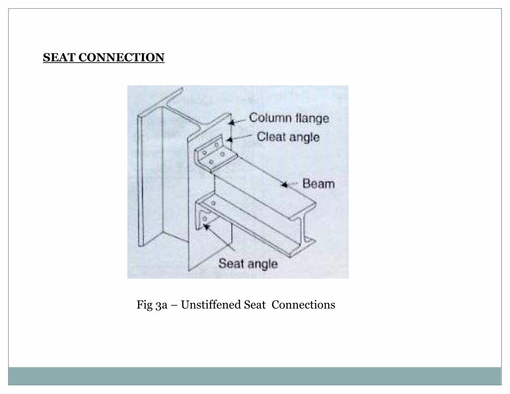
SEAT CONNECTION
Fig 3a – Unstiffened Seat Connections
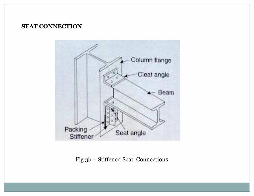
Fig 3b – Stiffened Seat Connections
SEAT CONNECTION
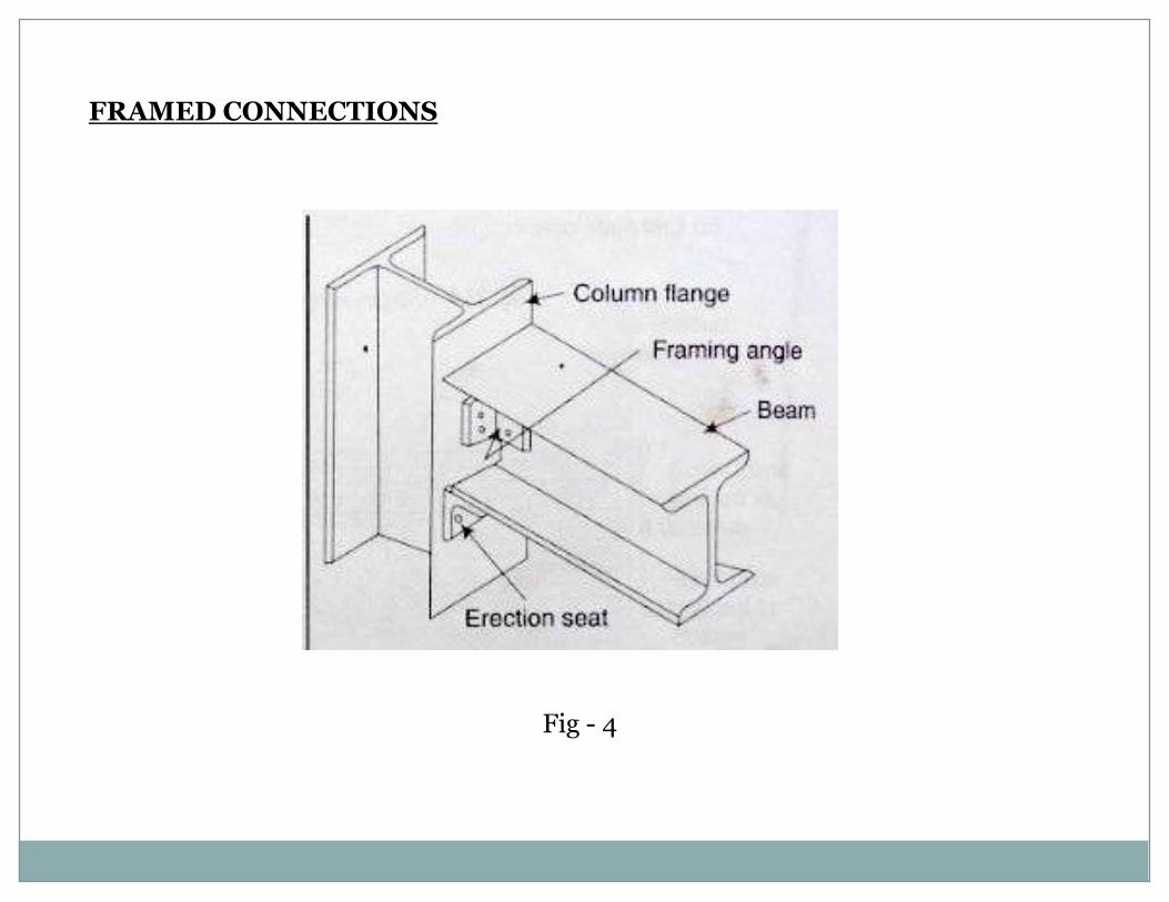
FRAMED CONNECTIONS
Fig - 4
BRACKET CONNECTIONS
1) Bolted bracket – type I connections2) Bolted bracket – type II connections3) Welded bracket – type I connections4) Welded bracket – type II connections
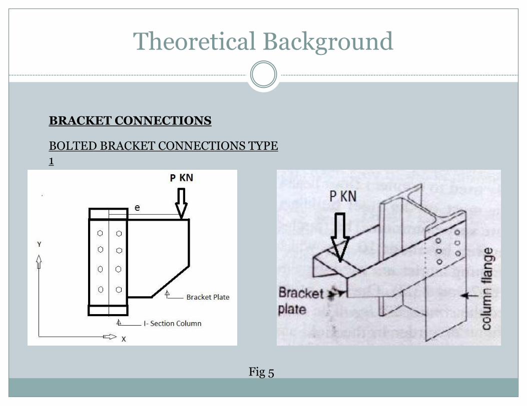
Theoretical Background
BRACKET CONNECTIONS
BOLTED BRACKET CONNECTIONS TYPE 1
Fig 5
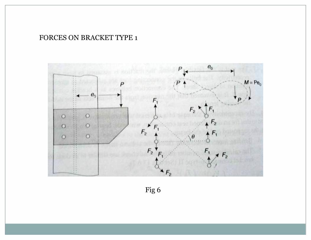
FORCES ON BRACKET TYPE 1
Fig 6
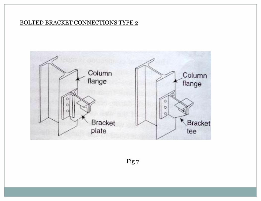
BOLTED BRACKET CONNECTIONS TYPE 2
Fig 7
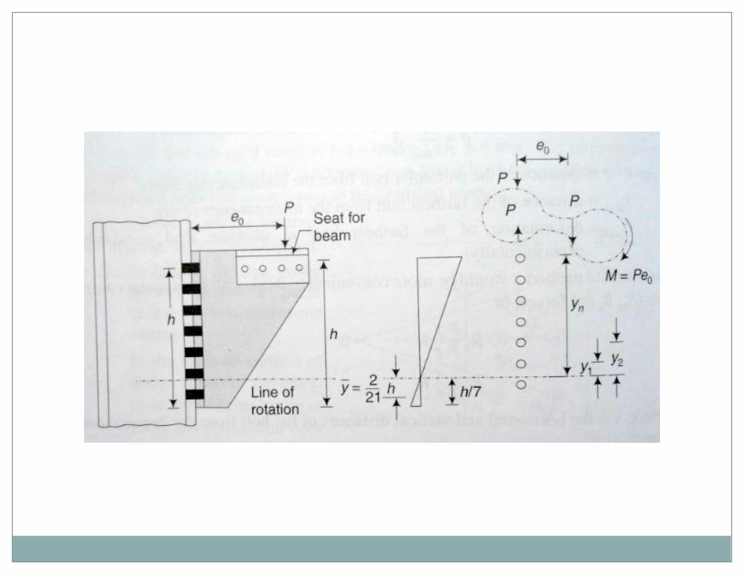
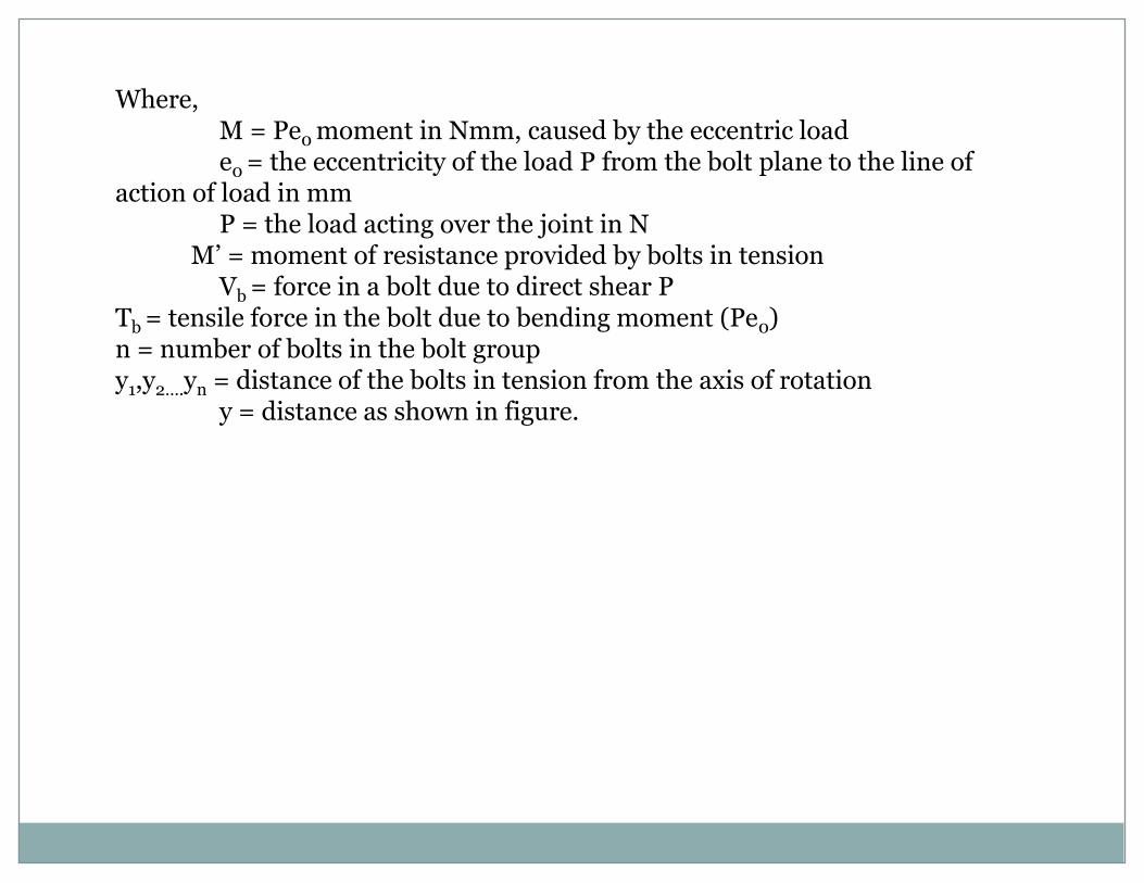
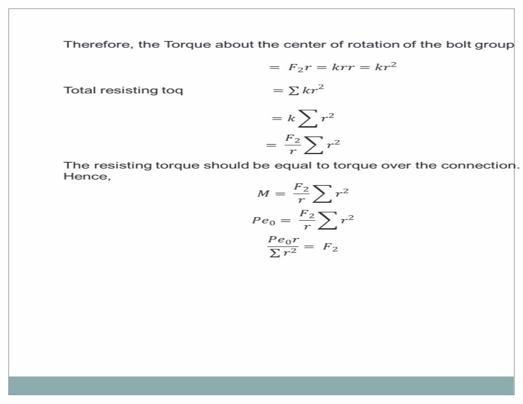
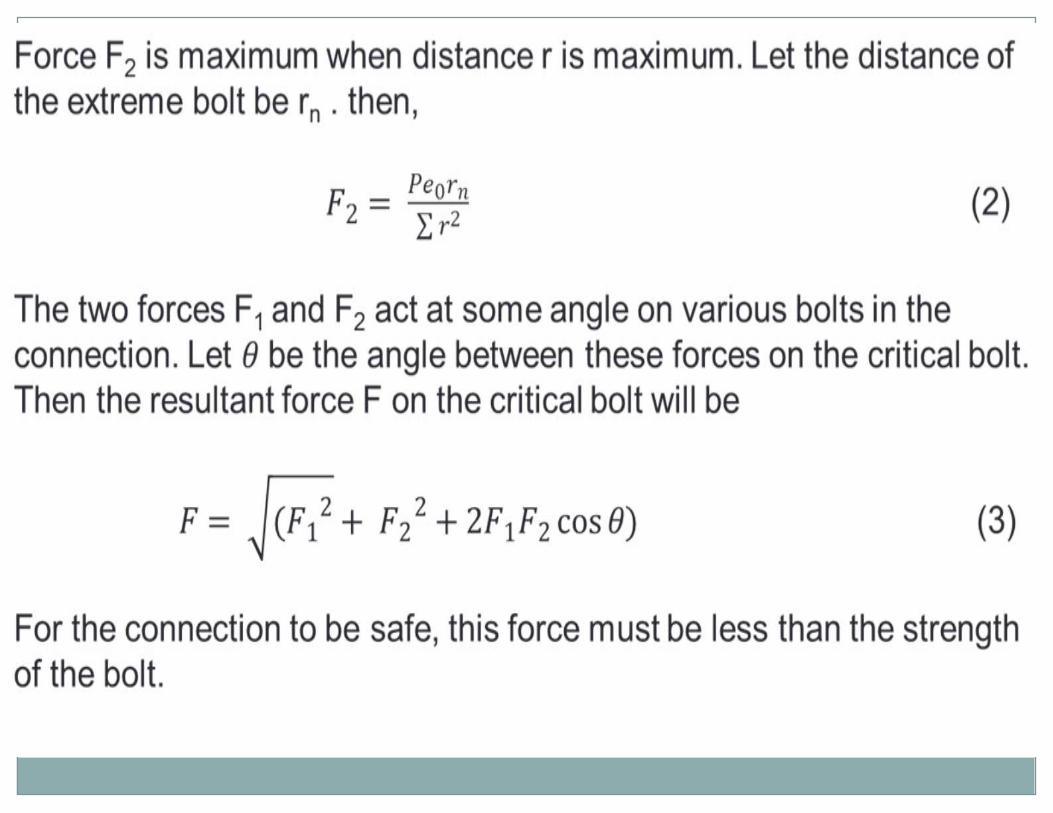
Where,M = Pe0 moment in Nmm, caused by the eccentric loade0 = the eccentricity of the load P from the bolt plane to the line of
action of load in mmP = the load acting over the joint in N
M’ = moment of resistance provided by bolts in tensionVb = force in a bolt due to direct shear P
Tb = tensile force in the bolt due to bending moment (Pe0)n = number of bolts in the bolt groupy1,y2….yn = distance of the bolts in tension from the axis of rotation
y = distance as shown in figure.
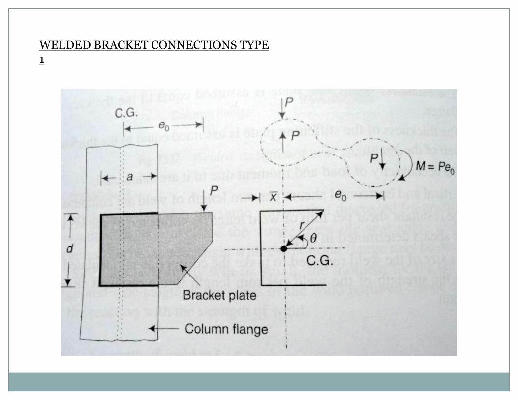
WELDED BRACKET CONNECTIONS TYPE 1
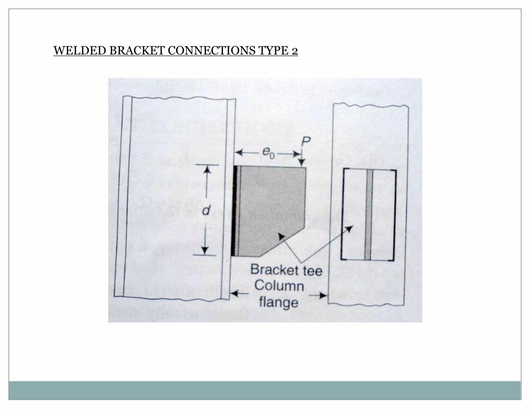
WELDED BRACKET CONNECTIONS TYPE 2
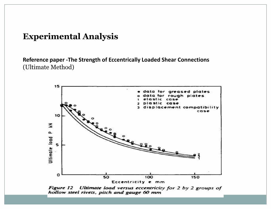
Experimental Analysis
Reference paper -The Strength of Eccentrically Loaded Shear Connections(Ultimate Method)
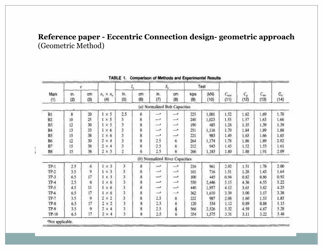
Reference paper - Eccentric Connection design- geometric approach(Geometric Method)
ANALYSIS AND DESIGN OF INDUSTRIAL
BUILDINGS
UNIT III
Design of Steel Structures
Example Problem
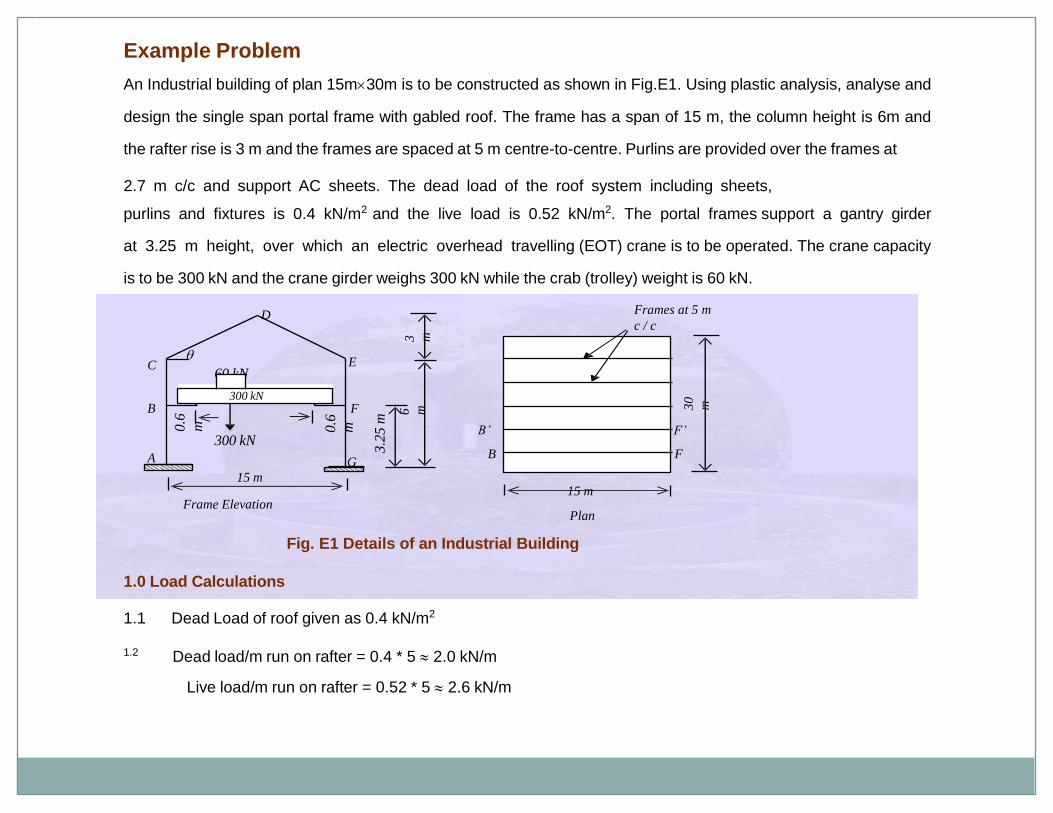
An Industrial building of plan 15m30m is to be constructed as shown in Fig.E1. Using plastic analysis, analyse and
design the single span portal frame with gabled roof. The frame has a span of 15 m, the column height is 6m and
the rafter rise is 3 m and the frames are spaced at 5 m centre-to-centre. Purlins are provided over the frames at
2.7 m c/c and support AC sheets. The dead load of the roof system including sheets,
purlins and fixtures is 0.4 kN/m2 and the live load is 0.52 kN/m2. The portal frames support a gantry girder
at 3.25 m height, over which an electric overhead travelling (EOT) crane is to be operated. The crane capacity
is to be 300 kN and the crane girder weighs 300 kN while the crab (trolley) weight is 60 kN.
Fig. E1 Details of an Industrial Building
1.0 Load Calculations
1.1 Dead Load of roof given as 0.4 kN/m2
Dead load/m run on rafter = 0.4 * 5 2.0 kN/m1.2
Live load/m run on rafter = 0.52 * 5 2.6 kN/m
15 m
Plan
30
m
Frames at 5 m
c / c
3 m
3.2
5 m
6 m
15 m
0.6
m 0.6
m
A
B
C
D
E
F
G
300 kN
60 kN
B
B’
F
F’
Frame Elevation
300 kN
Design of Steel Structures
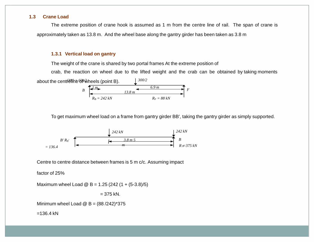
1.3 Crane Load
The extreme position of crane hook is assumed as 1 m from the centre line of rail. The span of crane is
approximately taken as 13.8 m. And the wheel base along the gantry girder has been taken as 3.8 m
1.3.1 Vertical load on gantry
The weight of the crane is shared by two portal frames At the extreme position of
crab, the reaction on wheel due to the lifted weight and the crab can be obtained by taking moments
about the centreline of wheels (point B).
To get maximum wheel load on a frame from gantry girder BB', taking the gantry girder as simply supported.
Centre to centre distance between frames is 5 m c/c. Assuming impact
factor of 25%
Maximum wheel Load @ B = 1.25 (242 (1 + (5-3.8)/5)
= 375 kN.
Minimum wheel Load @ B = (88 /242)*375
=136.4 kN
13.8 m
1 m
(300 + 60)/2 300/2
B F6.9 m
RB = 242 kN RF = 88 kN
242 kN 242 kN
3.8 m 5
m
B' RB1
= 136.4
B
R =375 kNB
Design of Steel Structures
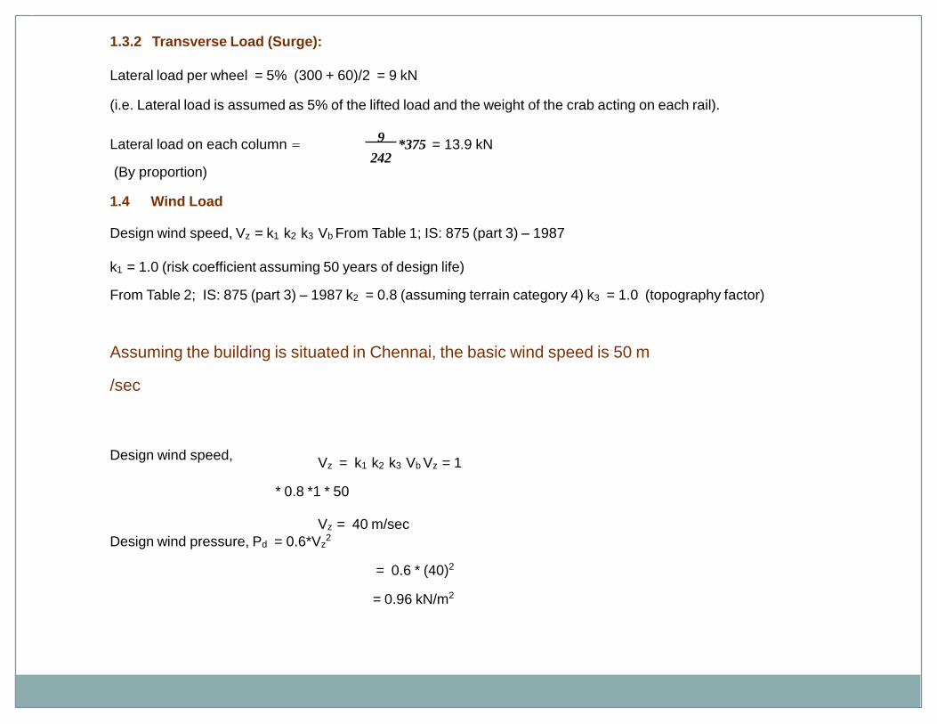
1.3.2 Transverse Load (Surge):
Lateral load per wheel = 5% (300 + 60)/2 = 9 kN
(i.e. Lateral load is assumed as 5% of the lifted load and the weight of the crab acting on each rail).
Lateral load on each column
(By proportion)
*375 = 13.9 kN9
242
1.4 Wind Load
Design wind speed, Vz = k1 k2 k3 Vb From Table 1; IS: 875 (part 3) – 1987
k1 = 1.0 (risk coefficient assuming 50 years of design life)
From Table 2; IS: 875 (part 3) – 1987 k2 = 0.8 (assuming terrain category 4) k3 = 1.0 (topography factor)
Assuming the building is situated in Chennai, the basic wind speed is 50 m
/sec
Design wind speed,Vz = k1 k2 k3 Vb Vz = 1
* 0.8 *1 * 50
Vz = 40 m/sec
Design wind pressure, Pd = 0.6*Vz2
= 0.6 * (40)2
= 0.96 kN/m2
Design of Steel Structures Prof. S.R.Satish Kumar and Prof. A.R.Santha Kumar
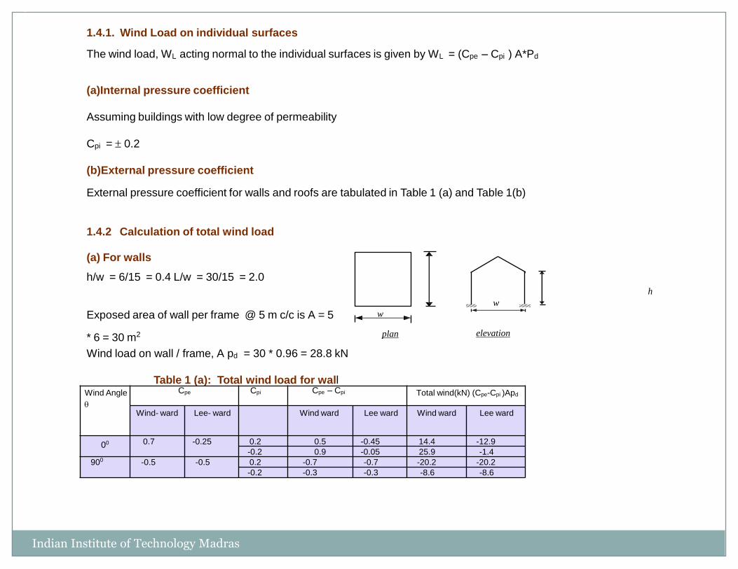
1.4.1. Wind Load on individual surfaces
The wind load, WL acting normal to the individual surfaces is given by WL = (Cpe – Cpi ) A*Pd
(a)Internal pressure coefficient
Assuming buildings with low degree of permeability
Cpi = 0.2
(b)External pressure coefficient
External pressure coefficient for walls and roofs are tabulated in Table 1 (a) and Table 1(b)
1.4.2 Calculation of total wind load
(a) For walls
h/w = 6/15 = 0.4 L/w = 30/15 = 2.0
h
Indian Institute of Technology Madras
w
w
plan elevation
Exposed area of wall per frame @ 5 m c/c is A = 5
* 6 = 30 m2
Wind load on wall / frame, A pd = 30 * 0.96 = 28.8 kN
Table 1 (a): Total wind load for wallWind Angle
Cpe Cpi Cpe – Cpi Total wind(kN) (Cpe-Cpi )Apd
Wind- ward Lee- ward Wind ward Lee ward Wind ward Lee ward
00 0.7 -0.25 0.2 0.5 -0.45 14.4 -12.9
-0.2 0.9 -0.05 25.9 -1.4
900 -0.5 -0.5 0.2 -0.7 -0.7 -20.2 -20.2
-0.2 -0.3 -0.3 -8.6 -8.6
Design of Steel Structures
15 m
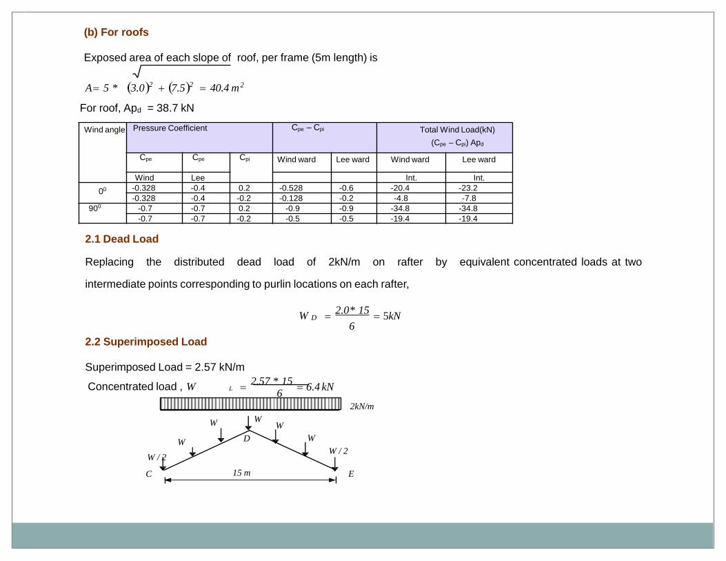
2.1 Dead Load
Replacing the distributed dead load of 2kN/m on rafter by equivalent concentrated loads at two
intermediate points corresponding to purlin locations on each rafter,
2.0* 15
5kN6
W D
2.2 Superimposed Load
Superimposed Load = 2.57 kN/m
Concentrated load , W 2.57 * 15
6.4 kN6
L
(b) For roofs
Exposed area of each slope of roof, per frame (5m length) is
A 5 * 3.02 7.52 40.4 m2
For roof, Apd = 38.7 kN
Table 1 (b): Total wind load for roof
2kN/m
C E
W
W WW
W
W / 2W / 2
D
Wind angle Pressure Coefficient Cpe – Cpi Total Wind Load(kN)
(Cpe – Cpi) Apd
Cpe Cpe Cpi Wind ward Lee ward Wind ward Lee ward
Wind Lee Int. Int.
00 -0.328 -0.4 0.2 -0.528 -0.6 -20.4 -23.2
-0.328 -0.4 -0.2 -0.128 -0.2 -4.8 -7.8
900 -0.7 -0.7 0.2 -0.9 -0.9 -34.8 -34.8
-0.7 -0.7 -0.2 -0.5 -0.5 -19.4 -19.4
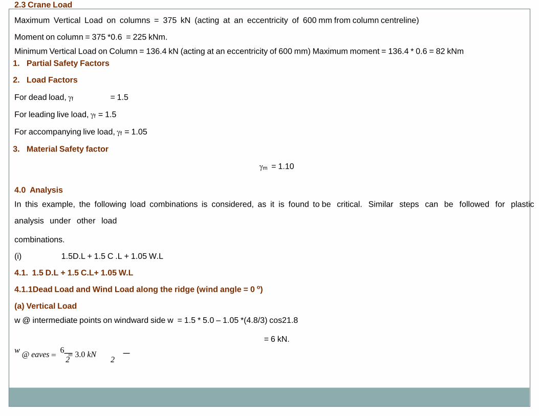
Design of Steel Structures2.3 Crane Load
Maximum Vertical Load on columns = 375 kN (acting at an eccentricity of 600 mm from column centreline)
Moment on column = 375 *0.6 = 225 kNm.
Minimum Vertical Load on Column = 136.4 kN (acting at an eccentricity of 600 mm) Maximum moment = 136.4 * 0.6 = 82 kNm
1. Partial Safety Factors
2. Load Factors
For dead load, f = 1.5
For leading live load, f = 1.5
For accompanying live load, f = 1.05
3. Material Safety factor
m = 1.10
4.0 Analysis
In this example, the following load combinations is considered, as it is found to be critical. Similar steps can be followed for plastic
analysis under other load
combinations.
(i) 1.5D.L + 1.5 C .L + 1.05 W.L
4.1. 1.5 D.L + 1.5 C.L+ 1.05 W.L
4.1.1Dead Load and Wind Load along the ridge (wind angle = 0 o)
(a) Vertical Load
w @ intermediate points on windward side w = 1.5 * 5.0 – 1.05 *(4.8/3) cos21.8
= 6 kN.
w @ eaves
6 3.0 kN
2 2
Design of Steel Structures
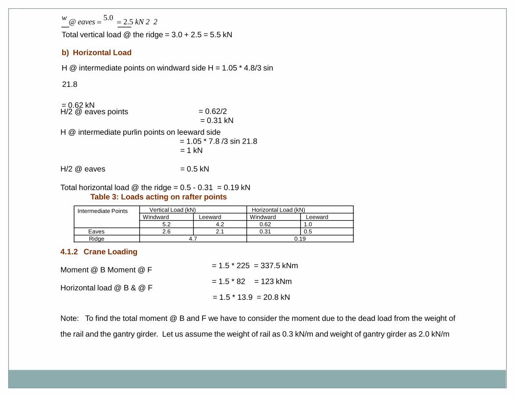
w @ eaves
5.0 2.5 kN 2 2
Total vertical load @ the ridge = 3.0 + 2.5 = 5.5 kN
b) Horizontal Load
H @ intermediate points on windward side H = 1.05 * 4.8/3 sin
21.8
= 0.62 kNH/2 @ eaves points = 0.62/2
= 0.31 kN
H @ intermediate purlin points on leeward side= 1.05 * 7.8 /3 sin 21.8= 1 kN
H/2 @ eaves = 0.5 kN
Total horizontal load @ the ridge = 0.5 - 0.31 = 0.19 kN
Table 3: Loads acting on rafter points
4.1.2 Crane Loading
Moment @ B Moment @ F
Horizontal load @ B & @ F
= 1.5 * 225 = 337.5 kNm
= 1.5 * 82 = 123 kNm
= 1.5 * 13.9 = 20.8 kN
Note: To find the total moment @ B and F we have to consider the moment due to the dead load from the weight of
the rail and the gantry girder. Let us assume the weight of rail as 0.3 kN/m and weight of gantry girder as 2.0 kN/m
Intermediate Points Vertical Load (kN) Horizontal Load (kN)
Windward Leeward Windward Leeward
5.2 4.2 0.62 1.0
Eaves 2.6 2.1 0.31 0.5
Ridge 4.7 0.19
Design of Steel Structures
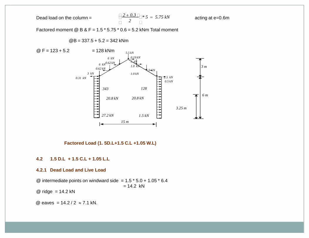
Dead load on the column = acting at e=0.6m
Factored moment @ B & F = 1.5 * 5.75 * 0.6 = 5.2 kNm Total moment
@B = 337.5 + 5.2 = 342 kNm
@ F = 123 + 5.2 = 128 kNm
Factored Load (1. 5D.L+1.5 C.L +1.05 W.L)
4.2 1.5 D.L + 1.5 C.L + 1.05 L.L
4.2.1 Dead Load and Live Load
@ intermediate points on windward side = 1.5 * 5.0 + 1.05 * 6.4= 14.2 kN
@ ridge = 14.2 kN
@ eaves = 14.2 / 2 7.1 kN.
* 5 5.75 kN2
2 0.3
15 m
3 m
6 m
3.25 m
20.8 kN20.8 kN
343 128
27.2 kN 1.5 kN
0.19 kN
5 kN
1.0 kN
5 kN1.0 kN
2.5 kN
0.5 kN
5.5 kN
6 kN
0.62 kN6 kN
0.62 kN
3 kN
0.31 kN
Design of Steel Structures
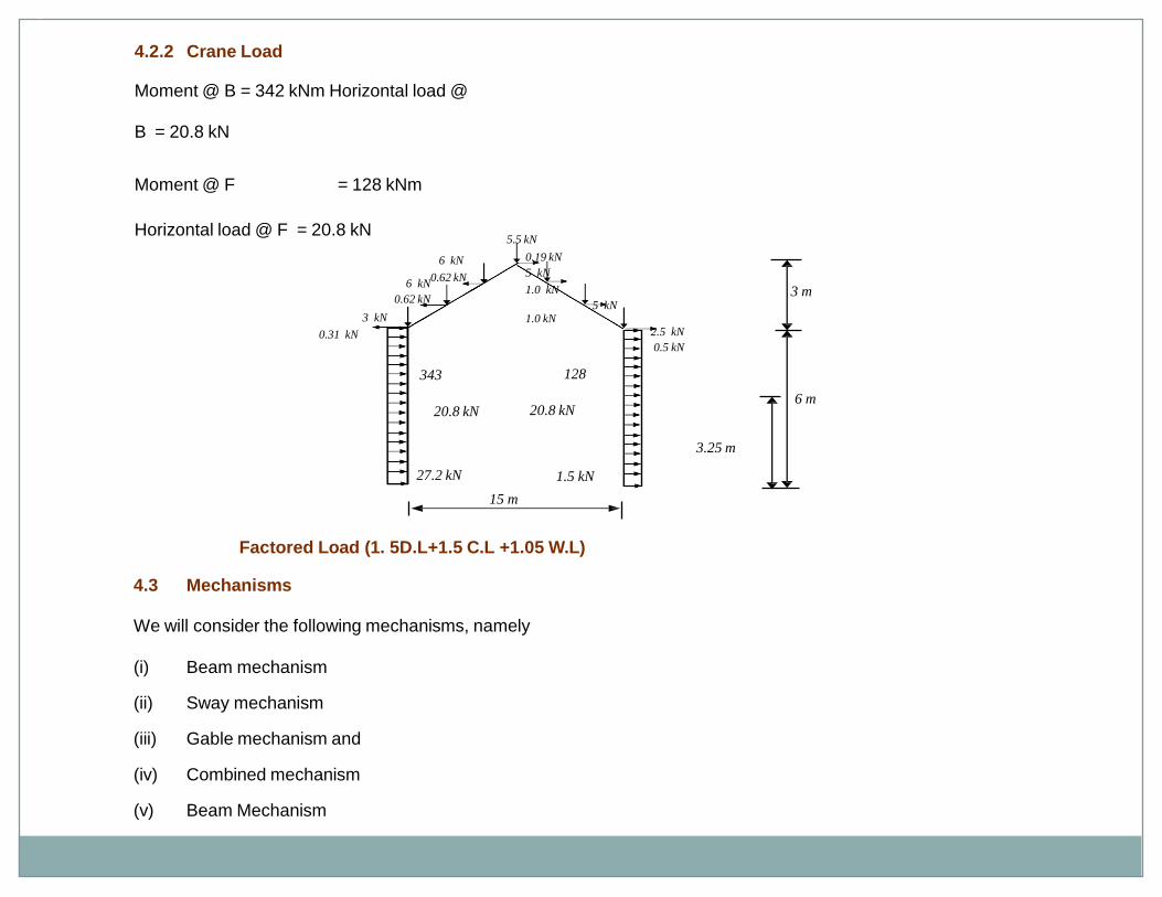
4.2.2 Crane Load
Moment @ B = 342 kNm Horizontal load @
B = 20.8 kN
Moment @ F = 128 kNm
Horizontal load @ F = 20.8 kN
Factored Load (1. 5D.L+1.5 C.L +1.05 W.L)
4.3 Mechanisms
We will consider the following mechanisms, namely
(i) Beam mechanism
(ii) Sway mechanism
(iii) Gable mechanism and
(iv) Combined mechanism
(v) Beam Mechanism
15 m
3 m
6 m
3.25 m
20.8 kN20.8 kN
343 128
27.2 kN 1.5 kN
0.19 kN
5 kN
1.0 kN
5 kN1.0 kN
2.5 kN
0.5 kN
5.5 kN
6 kN
0.62 kN6 kN
0.62 kN
3 kN
0.31 kN
Design of Steel Structures
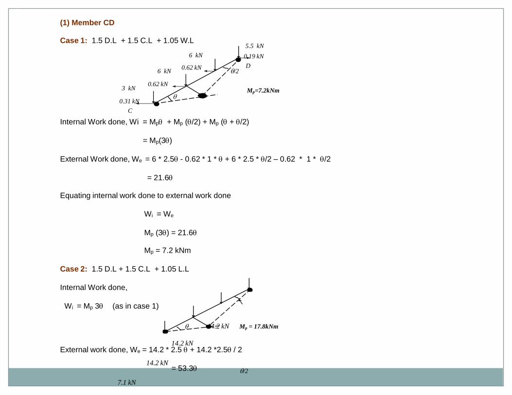
(1) Member CD
Case 1: 1.5 D.L + 1.5 C.L + 1.05 W.L
C
Internal Work done, Wi = Mp + Mp (/2) + Mp ( + /2)
= Mp(3)
External Work done, We = 6 * 2.5 - 0.62 * 1 * + 6 * 2.5 * /2 – 0.62 * 1 * /2
= 21.6
Equating internal work done to external work done
Wi = We
Mp (3) = 21.6
Mp = 7.2 kNm
Case 2: 1.5 D.L + 1.5 C.L + 1.05 L.L
Internal Work done,
Wi = Mp 3 (as in case 1)
14.2 kN
14.2 kN
14.2 kN/2
7.1 kN
External work done, We = 14.2 * 2.5 + 14.2 *2.5 / 2
= 53.3
D
5.5 kN
0.19 kN
6 kN
0.62 kN
6 kN
0.62 kN
3 kN
0.31 kN
/2
Mp=7.2kNm
Mp = 17.8kNm
Design of Steel Structures
.
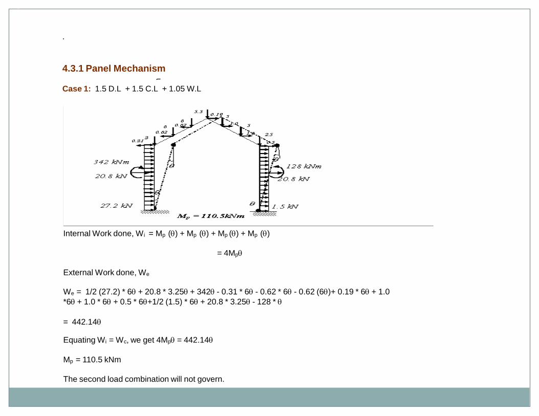
4.3.1 Panel Mechanism
Case 1: 1.5 D.L + 1.5 C.L + 1.05 W.L
Internal Work done, W i = Mp () + Mp () + Mp () + Mp ()
= 4Mp
External Work done, We
We = 1/2 (27.2) * 6 + 20.8 * 3.25 + 342 - 0.31 * 6 - 0.62 * 6 - 0.62 (6)+ 0.19 * 6 + 1.0
*6 + 1.0 * 6 + 0.5 * 6+1/2 (1.5) * 6 + 20.8 * 3.25 - 128 *
= 442.14
Equating Wi = Wc, we get 4Mp = 442.14
Mp = 110.5 kNm
The second load combination will not govern.
Design of Steel Structures
14.2
14.2
14.2
14.2
7.1
14.2
20.8 kN
20.8 kN
342 kNm 128 kNm
7.1
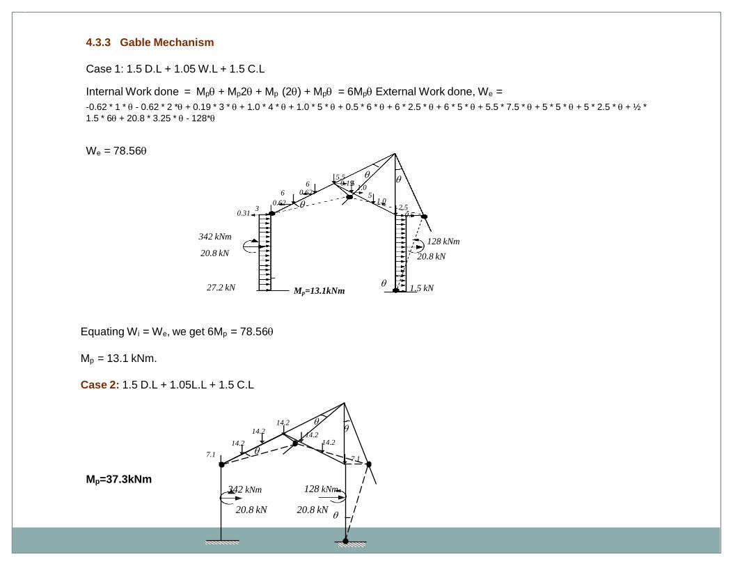
4.3.3 Gable Mechanism
Case 1: 1.5 D.L + 1.05 W.L + 1.5 C.L
Internal Work done = Mp + Mp2 + Mp (2) + Mp = 6Mp External Work done, We =
-0.62 * 1 * - 0.62 * 2 * + 0.19 * 3 * + 1.0 * 4 * + 1.0 * 5 * + 0.5 * 6 * + 6 * 2.5 * + 6 * 5 * + 5.5 * 7.5 * + 5 * 5 * + 5 * 2.5 * + ½ *
1.5 * 6 + 20.8 * 3.25 * - 128*
We = 78.56
Equating Wi = We, we get 6Mp = 78.56
Mp = 13.1 kNm.
Case 2: 1.5 D.L + 1.05L.L + 1.5 C.L
Mp=37.3kNm
1.0
51.0
2.50.5
0.195.5
5
60.626
0.623
0.31
20.8 kN
342 kNm
20.8 kN
128 kNm
27.2 kN 1.5 kNMp=13.1kNm
Design of Steel Structures
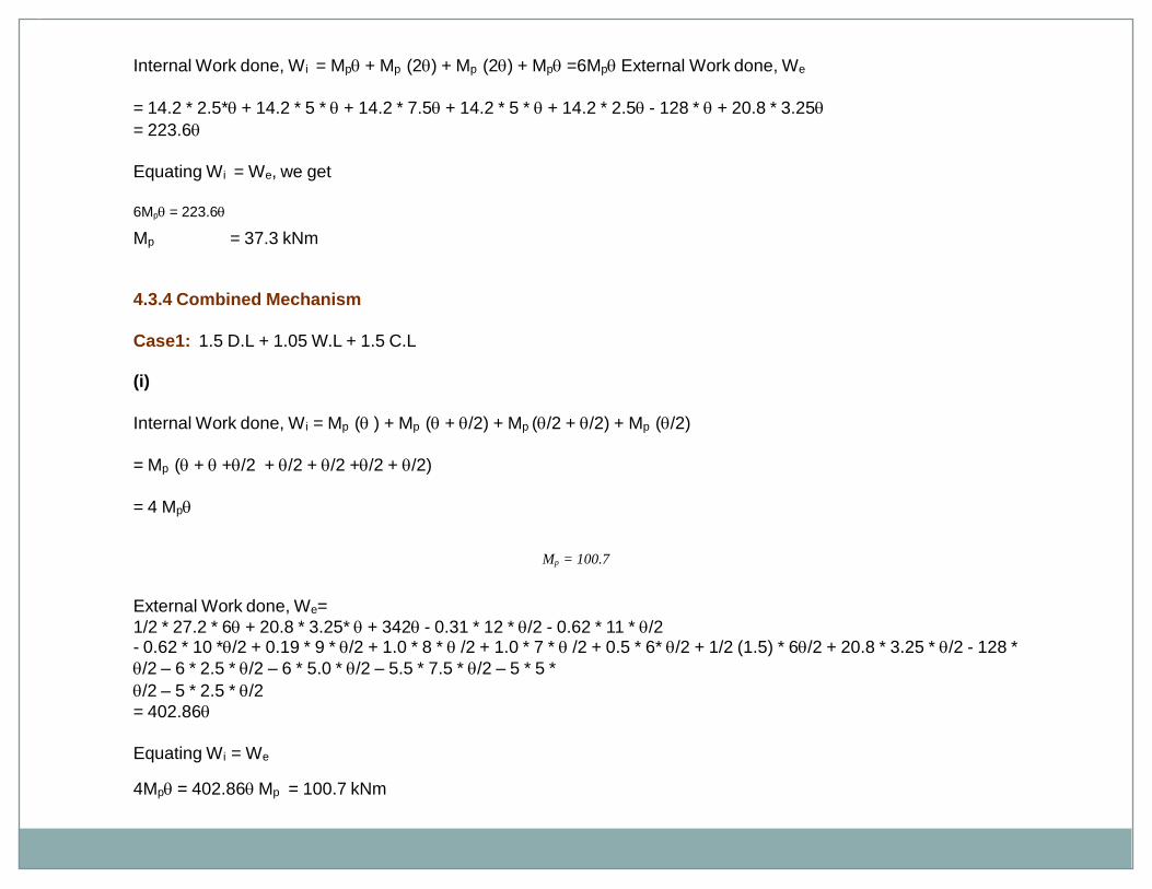
Internal Work done, W i = Mp + Mp (2) + Mp (2) + Mp =6Mp External Work done, We
= 14.2 * 2.5* + 14.2 * 5 * + 14.2 * 7.5 + 14.2 * 5 * + 14.2 * 2.5 - 128 * + 20.8 * 3.25
= 223.6
Equating Wi = We, we get
6Mp = 223.6
Mp = 37.3 kNm
4.3.4 Combined Mechanism
Case1: 1.5 D.L + 1.05 W.L + 1.5 C.L
(i)
Internal Work done, W i = Mp ( ) + Mp ( + /2) + Mp (/2 + /2) + Mp (/2)
= Mp ( + +/2 + /2 + /2 +/2 + /2)
= 4 Mp
Mp = 100.7
External Work done, We=
1/2 * 27.2 * 6 + 20.8 * 3.25* + 342 - 0.31 * 12 * /2 - 0.62 * 11 * /2- 0.62 * 10 */2 + 0.19 * 9 * /2 + 1.0 * 8 * /2 + 1.0 * 7 * /2 + 0.5 * 6* /2 + 1/2 (1.5) * 6/2 + 20.8 * 3.25 * /2 - 128 *
/2 – 6 * 2.5 * /2 – 6 * 5.0 * /2 – 5.5 * 7.5 * /2 – 5 * 5 *
/2 – 5 * 2.5 * /2
= 402.86
Equating Wi = We
4Mp = 402.86 Mp = 100.7 kNm
Design of Steel Structures
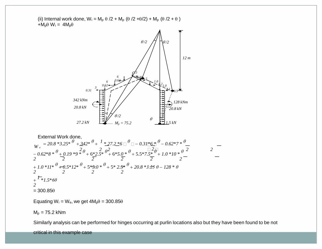
0.62*8 * θ 0.19 *9 *
θ 6*2.5*
θ 6*5.0 *
θ 5.5*7.5*
θ 1.0 *10 *
θ
2 2 2 2 2 2
1.0 *11* θ 0.5*12*
θ 5*5.0 *
θ 5* 2.5*
θ 20.8 *3.25 θ 128 * θ
2 2 2 2
1
*1.5*6θ2
= 300.85
Equating Wi = We, we get 4Mp = 300.85
Mp = 75.2 kNm
Similarly analysis can be performed for hinges occurring at purlin locations also but they have been found to be not
critical in this example case
2 2
20.8 *3.25* θ 342*
θ
1 * 27.2 *6
θ 0.31*6 *
θ 0.62*7 *
θ
2 2 2 2W e
(ii) Internal work done, W i = Mp /2 + Mp ( /2 +/2) + Mp ( /2 + )+Mp W i = 4Mp
External Work done,
/2
/2 /2
20.8 kN
342 kNm
20.8 kN
128 kNm
27.2 kN 1.5 kN
1.02.1
1.0
0.5
5.5
0.195
4.2
60.626
0.623
0.31
12 m
Mp = 75.2
Design of Steel Structures
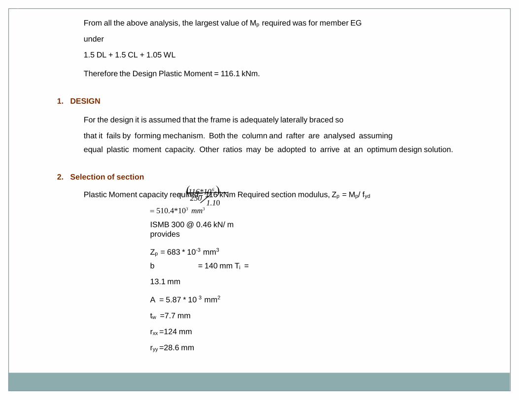
From all the above analysis, the largest value of Mp required was for member EG
under
1.5 DL + 1.5 CL + 1.05 WL
Therefore the Design Plastic Moment = 116.1 kNm.
1. DESIGN
For the design it is assumed that the frame is adequately laterally braced so
that it fails by forming mechanism. Both the column and rafter are analysed assuming
equal plastic moment capacity. Other ratios may be adopted to arrive at an optimum design solution.
2. Selection of section
Plastic Moment capacity required= 116 kNm Required section modulus, Zp = Mp/ fyd
510.4*103 mm3
ISMB 300 @ 0.46 kN/ m
provides
Zp = 683 * 10-3 mm3
b = 140 mm Ti =
13.1 mm
A = 5.87 * 10 3 mm2
tw =7.7 mm
rxx =124 mm
ryy =28.6 mm
116*106 1.10
250
UNIT IV
DESIGN OF STEEL TRUSS GIRDERBRIDGES
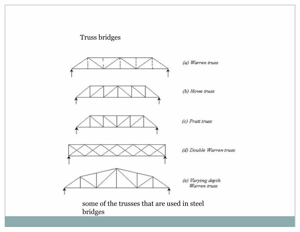
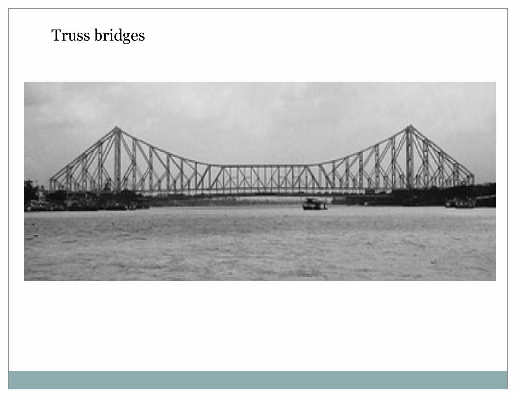
Truss bridges
some of the trusses that are used in steel bridges
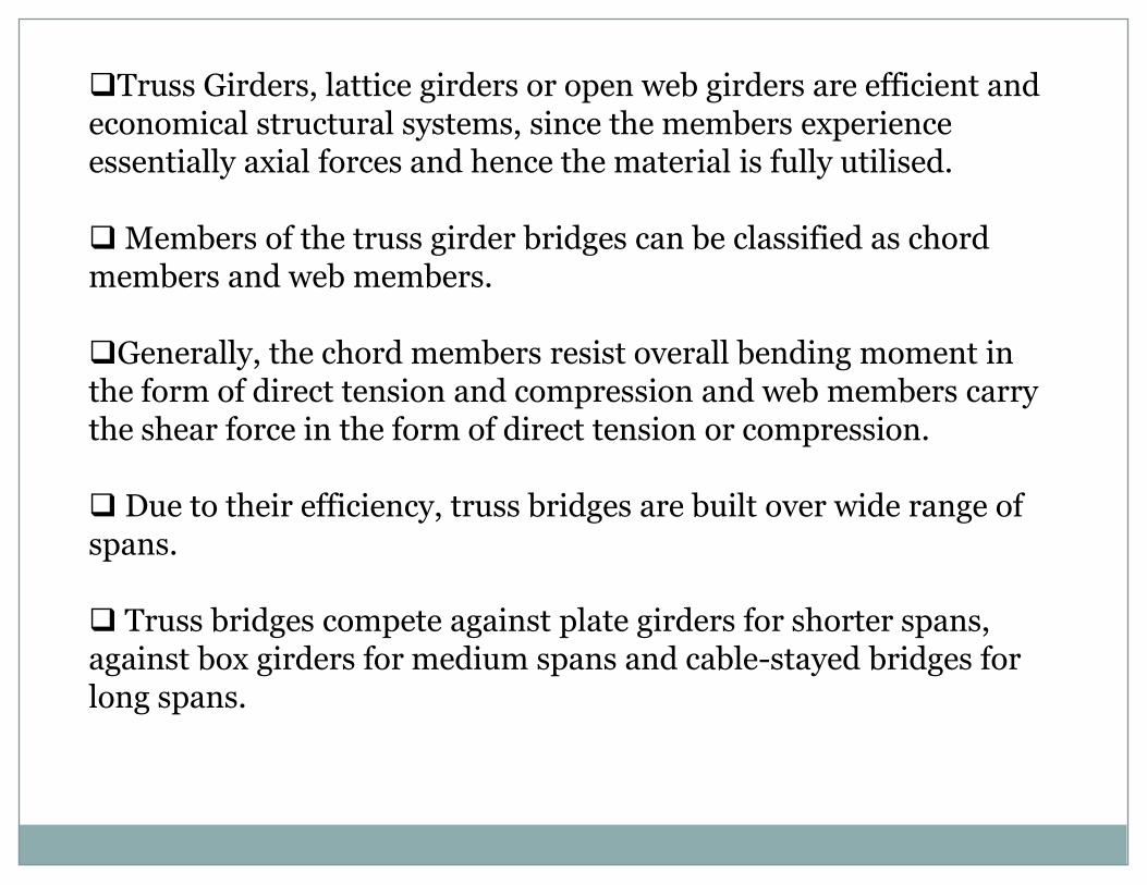
Truss Girders, lattice girders or open web girders are efficient and economical structural systems, since the members experience essentially axial forces and hence the material is fully utilised.
Members of the truss girder bridges can be classified as chord members and web members.
Generally, the chord members resist overall bending moment in the form of direct tension and compression and web members carry the shear force in the form of direct tension or compression.
Due to their efficiency, truss bridges are built over wide range of spans.
Truss bridges compete against plate girders for shorter spans, against box girders for medium spans and cable-stayed bridges for long spans.
General design principles
Optimum depth of truss girder
• The optimum value for span to depth ratio depends on the magnitude of the live load that has to be carried.
• The span to depth ratio of a truss girder bridge producing the greatest economy of material is that which makes the weight of chord members nearly equal to the weight of web members of truss.
• It will be in the region of 10, being greater for road traffic than for rail traffic.
Design of compression chord members
Generally, the effective length for the buckling of compression chord member in the plane of truss is not same as that for buckling out-of-plane of the truss i.e. the member is weak in one plane compared to the other.
The ideal compression chord will be one that has a section with radii of gyration such that the slenderness value is same in both planes.
In other words, the member is just likely to buckle in plane or out of plane.
These members should be kept as short as possible and consideration is given to additional bracing, if economical.
Design of tension chord members
•Tension members should be as compact as possible, but depths have to be large enough to provide adequate space for bolts at the gusset positions and easily attach cross beam.
• The width out-of-plane of the truss should be the same as that of the verticals and diagonals so that simple lapping gussets can be provided without the need for packing.
•It should be possible to achieve a net section about 85% of the gross section by careful arrangement of the bolts in the splices.
• This means that fracture at the net section will not govern for common steel grades.
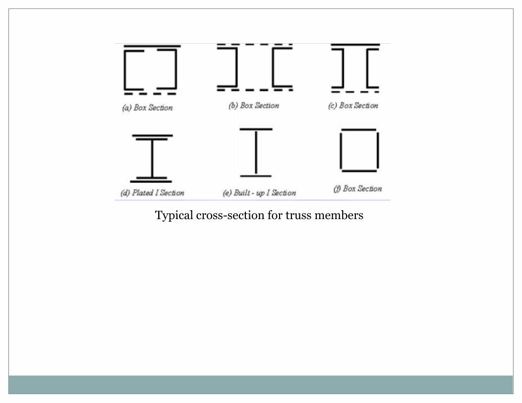
Typical cross-section for truss members
Design of vertical and diagonal members
Diagonal and vertical members are often rolled sections, particularly for the lightly loaded members, but packing may be required for making up the rolling margins
. This fact can make welded members more economical, particularly on the longer trusses where the packing operation might add significantly to the erection cost.
Aesthetically, it is desirable to keep all diagonals at the same angle, even if the chords are not parallel.
This arrangement prevents the truss looking overcomplexwhen viewed from an angle.
In practice, however, this is usually overruled by the economies of the deck structure where a constant panel length is to be preferred.
Lateral bracing for truss bridges
Lateral bracing in truss bridges is provided for transmitting the longitudinal live loads and lateral loads to the bearings and also to prevent the compression chords from buckling.
This is done by providing stringer bracing, braking girders and chord lateral bracing.
In case of highway truss bridges, concrete deck, if provided, also acts as lateral bracing support system.
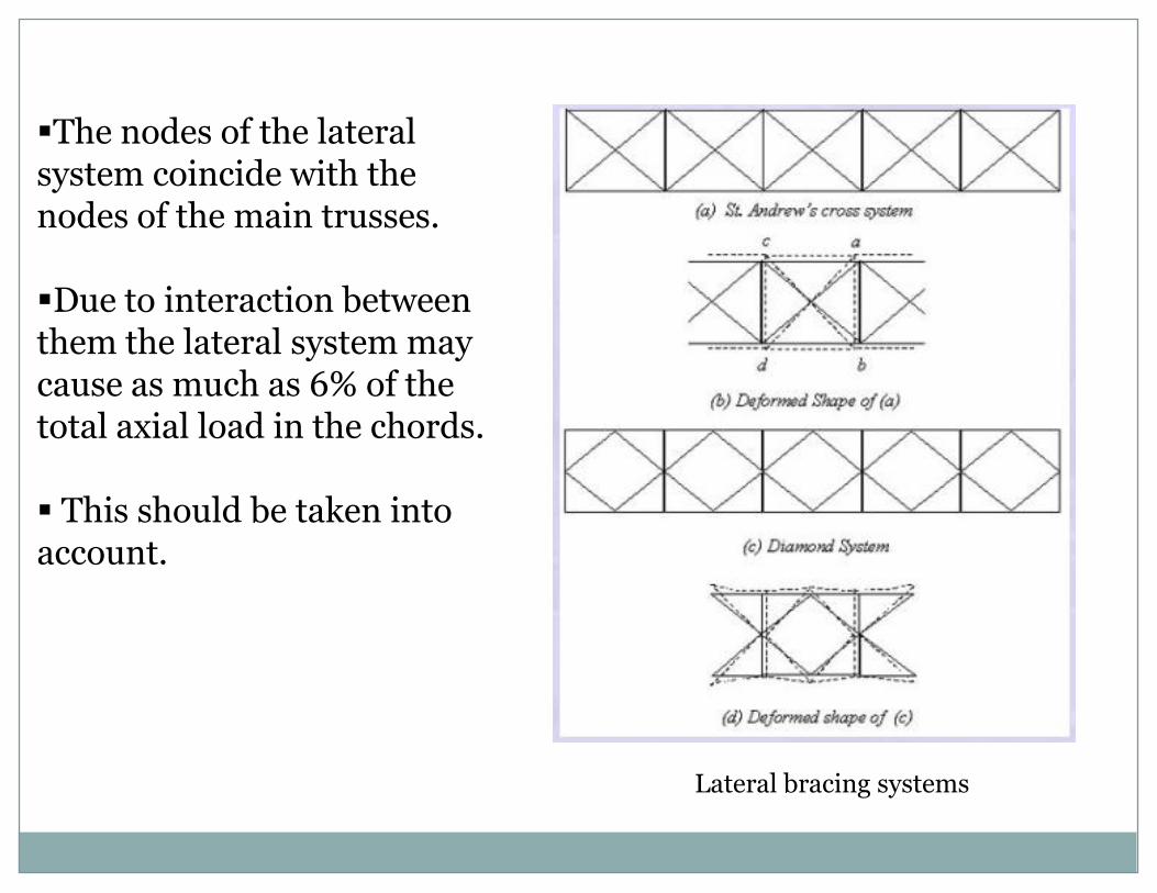
The nodes of the lateral system coincide with the nodes of the main trusses.
Due to interaction between them the lateral system may cause as much as 6% of the total axial load in the chords.
This should be taken into account.
Lateral bracing systems
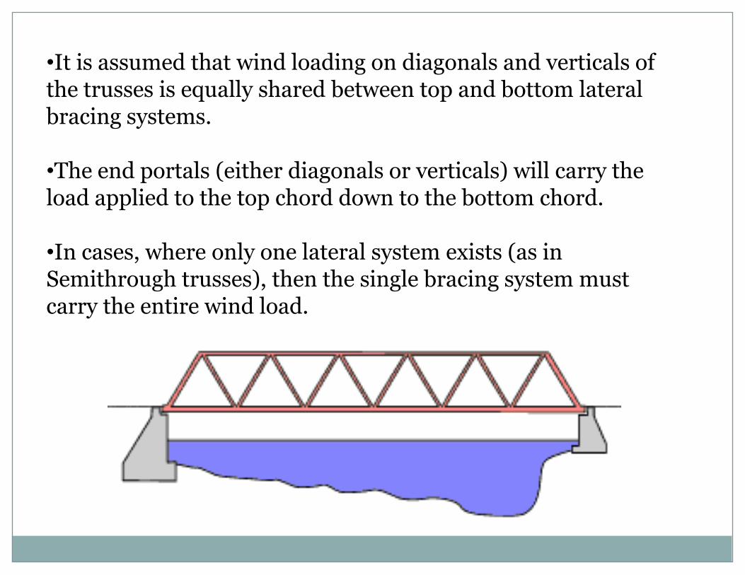
•It is assumed that wind loading on diagonals and verticals of the trusses is equally shared between top and bottom lateral bracing systems.
•The end portals (either diagonals or verticals) will carry the load applied to the top chord down to the bottom chord.
•In cases, where only one lateral system exists (as in Semithrough trusses), then the single bracing system must carry the entire wind load.
Truss bridges
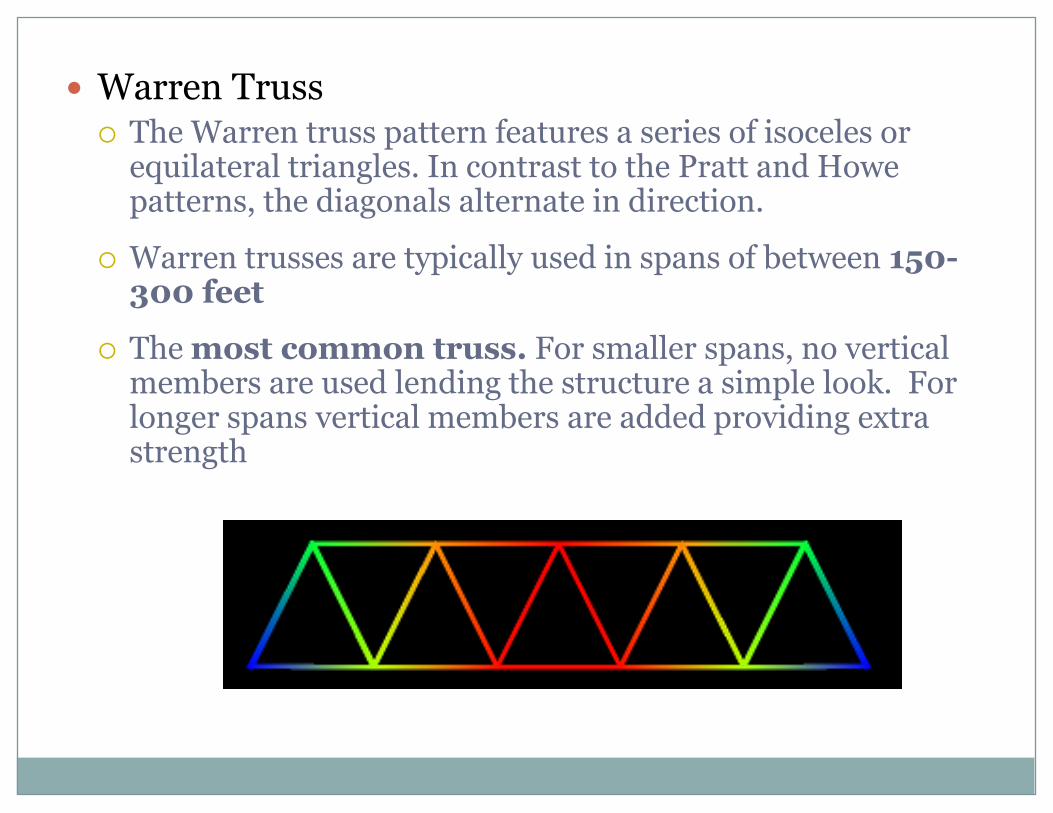
Warren Truss The Warren truss pattern features a series of isoceles or
equilateral triangles. In contrast to the Pratt and Howe patterns, the diagonals alternate in direction.
Warren trusses are typically used in spans of between 150-300 feet
The most common truss. For smaller spans, no vertical members are used lending the structure a simple look. For longer spans vertical members are added providing extra strength
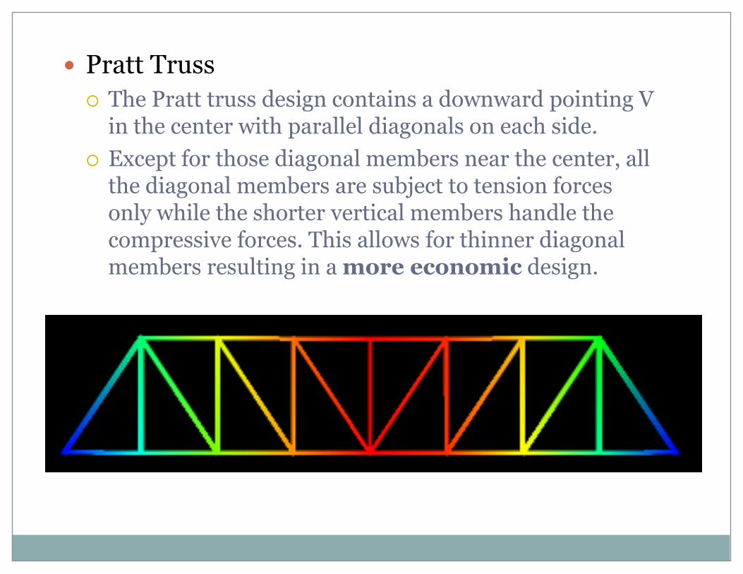
Pratt Truss
The Pratt truss design contains a downward pointing V in the center with parallel diagonals on each side.
Except for those diagonal members near the center, all the diagonal members are subject to tension forces only while the shorter vertical members handle the compressive forces. This allows for thinner diagonal members resulting in a more economic design.

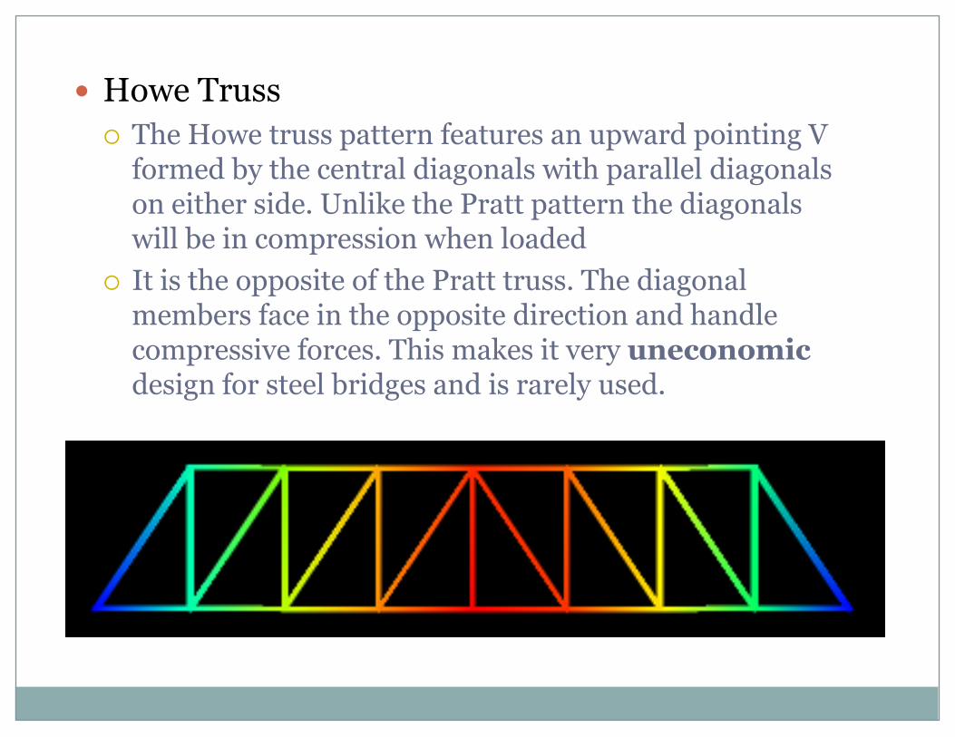
Howe Truss
The Howe truss pattern features an upward pointing V formed by the central diagonals with parallel diagonals on either side. Unlike the Pratt pattern the diagonals will be in compression when loaded
It is the opposite of the Pratt truss. The diagonal members face in the opposite direction and handle compressive forces. This makes it very uneconomicdesign for steel bridges and is rarely used.
UNIT V
DESIGN OF STEEL BUNKERS & SILOS
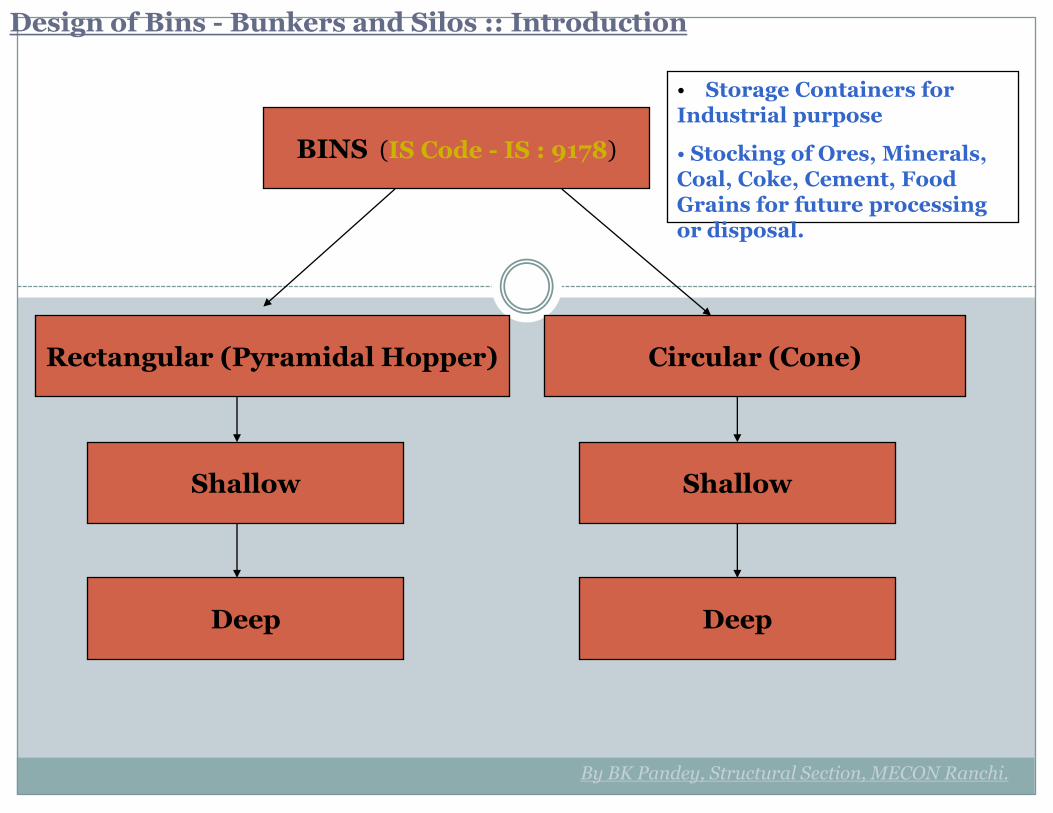
Design of Bins - Bunkers and Silos :: Introduction
BINS (IS Code - IS : 9178)
Rectangular (Pyramidal Hopper) Circular (Cone)
Shallow
Deep
Shallow
Deep
By BK Pandey, Structural Section, MECON Ranchi.
• Storage Containers for Industrial purpose
• Stocking of Ores, Minerals, Coal, Coke, Cement, Food Grains for future processing or disposal.
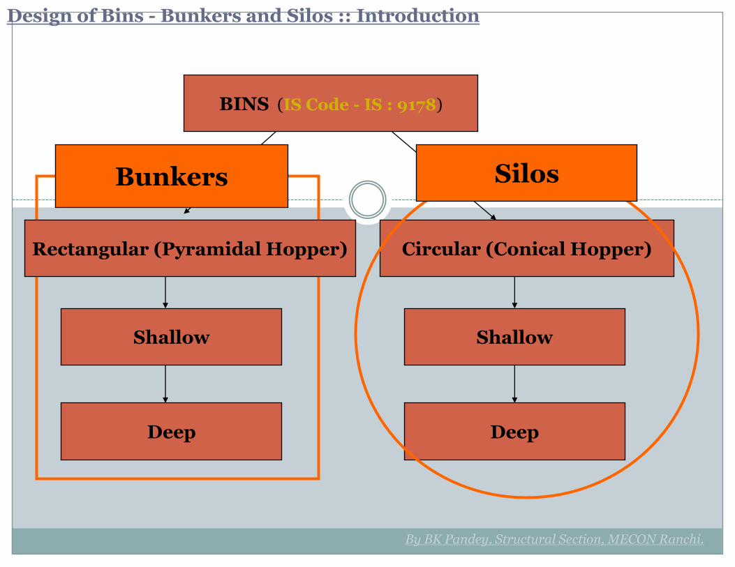
BINS (IS Code - IS : 9178)
Rectangular (Pyramidal Hopper) Circular (Conical Hopper)
Shallow
Deep
Shallow
Deep
Bunkers Silos
By BK Pandey, Structural Section, MECON Ranchi.
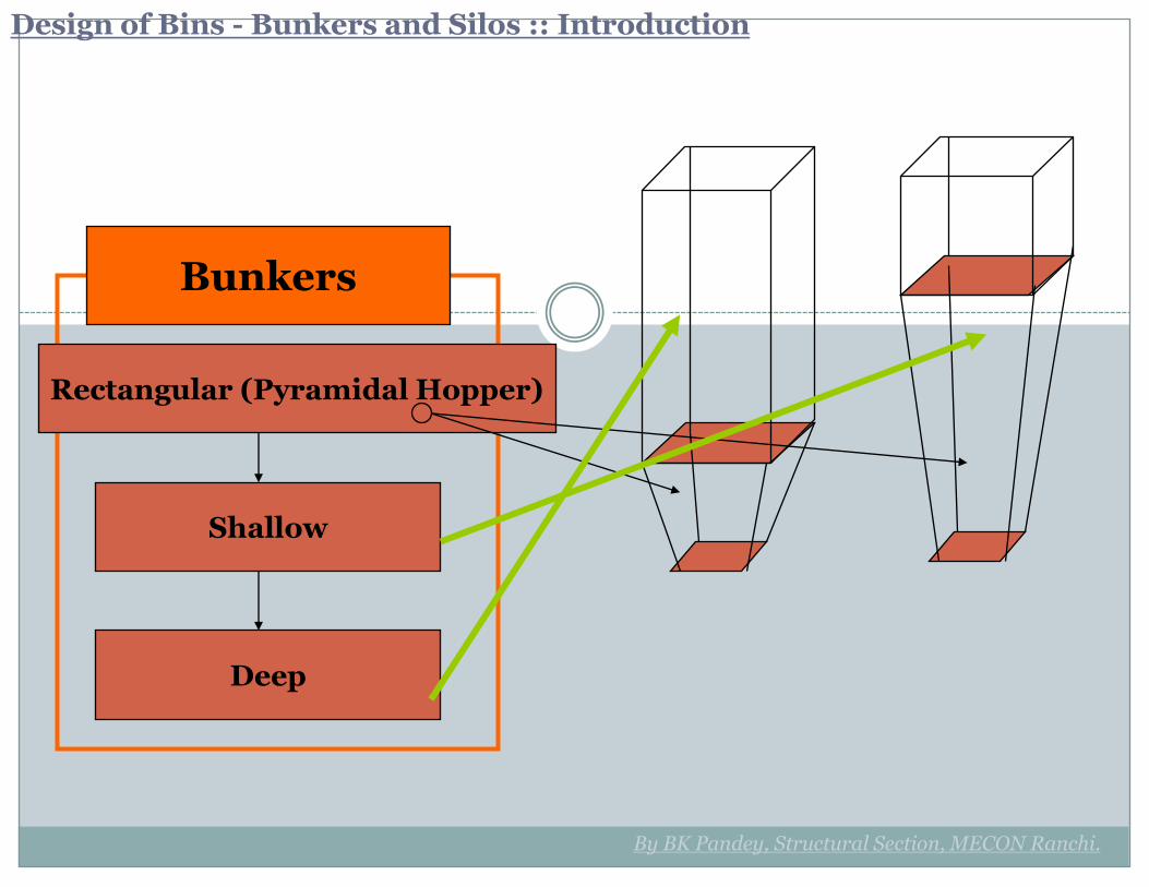
Design of Bins - Bunkers and Silos :: Introduction

Rectangular (Pyramidal Hopper)
Shallow
Deep
Bunkers
By BK Pandey, Structural Section, MECON Ranchi.
Design of Bins - Bunkers and Silos :: Introduction
Rectangular (Pyramidal Hopper)
Shallow
Deep
Bunkers
By BK Pandey, Structural Section, MECON Ranchi.
Design of Bins - Bunkers and Silos :: Introduction
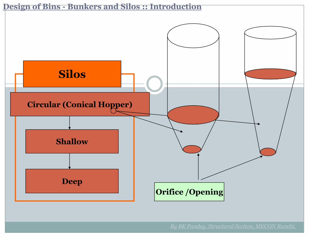
Circular (Conical Hopper)
Shallow
Deep
Silos
By BK Pandey, Structural Section, MECON Ranchi.
Orifice /Opening
Design of Bins - Bunkers and Silos :: Introduction
By BK Pandey, Structural Section, MECON Ranchi.
Design of Bins - Bunkers and Silos :: Design Considerations
1. Filling the Bunker – Feed and Loading
arrangement at the top.• Conveyor / Tripper Conveyor Feed• Bucket Elevator Feed• Other Mechanical Considerations.
2. Emptying the bunker *• free flow from Bottom opening or orifice• avoid Material Arching, Make use mechanical
vibrator.• Plan orifice locations to overcome discharge
problem.
3. Stocking of Material• Bunker Hopper + Wall system to be designed
strong enough to stock the material for the required duration.
• Proper application of Design Theories based on geometry of bunker + Nature of material to be stocked + type of filling and emptying.
By BK Pandey, Structural Section, MECON Ranchi.
Design of Bins - Bunkers and Silos :: Design Considerations
4. Provision of Wearing Surface – * Use of
liner plates and ease of Maintenance • Rubber Liner, SS/MS Plates, Grating• Bricks or Tiles
5. Minimum Slope of Trough• 50 to 60 degree Wall slope.• Consider Corner Angle for Pyramidal Bottom.
6. Guarding Against Over Loading• Application of Load Cells at support point.
7. Method of Support• Bunker supporting Beam Arrangement.• Bunker Supporting Beam Connections with
Portal Frames of Building.• Battery of Bunkers – Common Beams,
Continuous, Multi Span Beams.
By BK Pandey, Structural Section, MECON Ranchi.
Design of Bins - Bunkers and Silos :: Design Considerations
8. Materials of Construction & Method of Construction
• MS Welded Construction as per IS:800-1984, IS-814,
• MS Plates/Sections IS:2062 Gr-A.• SAIL-MA or High Yield Stress Wieldable
Structural Steel may turn out to be economical for large span bunker beams spanning more than 9 m.
9. Factors of Safety and Working Stresses
• Building Frame Loading as per IS-875 (Dead + Live + Wind), IS-1893 (Eq. Load) and IS:9178 ( Material Density and Angle of repose).
• Working stresses as per IS:800-1984.
By BK Pandey, Structural Section, MECON Ranchi.
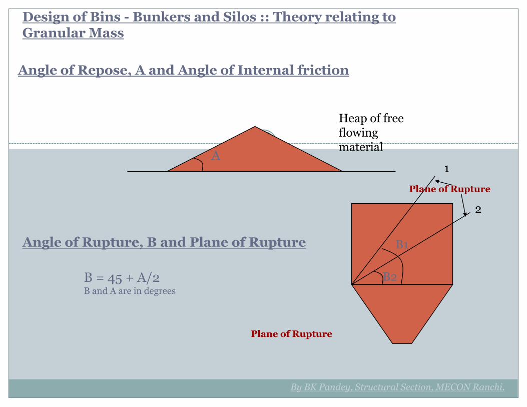
Design of Bins - Bunkers and Silos :: Theory relating to Granular Mass
Angle of Repose, A and Angle of Internal friction
Heap of free flowing material
A
Angle of Rupture, B and Plane of Rupture B1
B = 45 + A/2B and A are in degrees
1
2
B2
Plane of Rupture
Plane of Rupture
B1
By BK Pandey, Structural Section, MECON Ranchi.
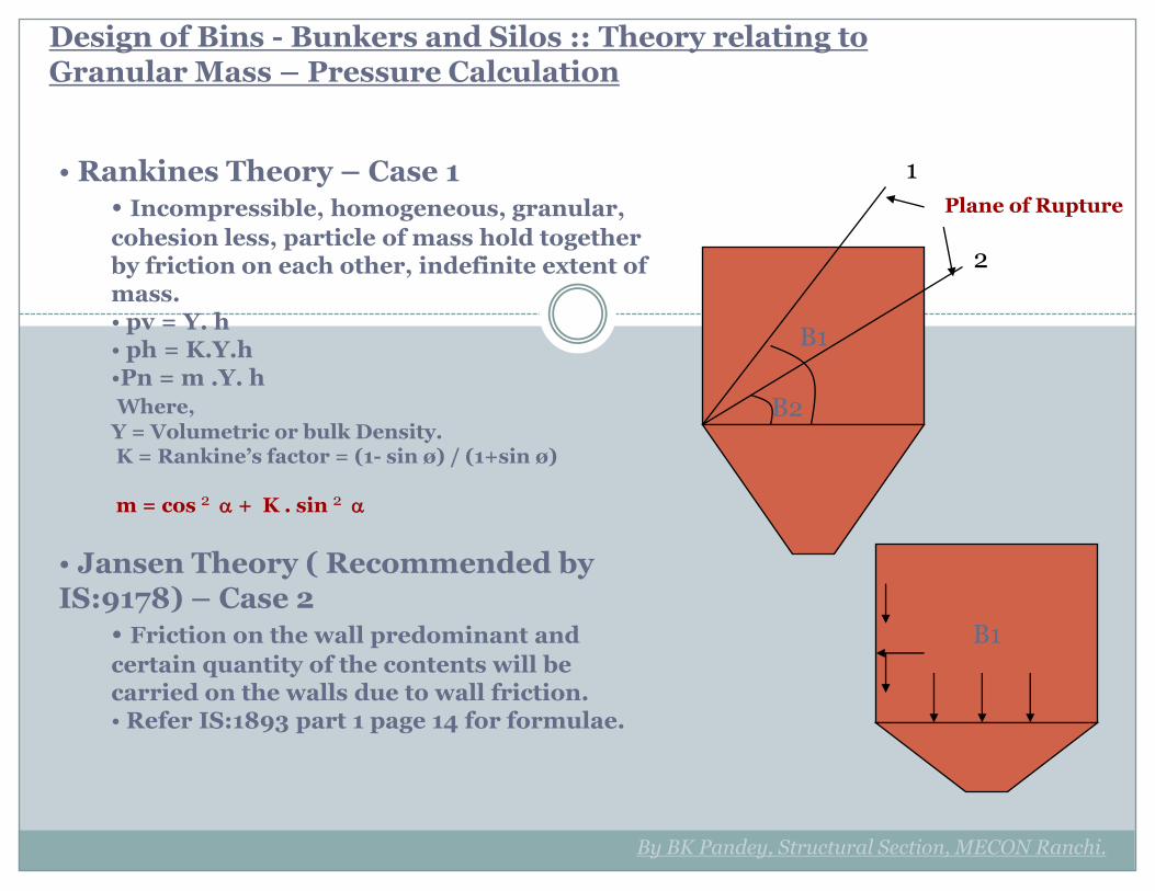
Design of Bins - Bunkers and Silos :: Theory relating to Granular Mass – Pressure Calculation
• Rankines Theory – Case 1• Incompressible, homogeneous, granular,
cohesion less, particle of mass hold together by friction on each other, indefinite extent of mass.• pv = Y. h• ph = K.Y.h•Pn = m .Y. hWhere,
Y = Volumetric or bulk Density.K = Rankine’s factor = (1- sin ø) / (1+sin ø)
m = cos 2 + K . sin 2
• Jansen Theory ( Recommended by IS:9178) – Case 2
• Friction on the wall predominant and
certain quantity of the contents will be carried on the walls due to wall friction.• Refer IS:1893 part 1 page 14 for formulae.
B1
1
2
B2
Plane of Rupture
By BK Pandey, Structural Section, MECON Ranchi.
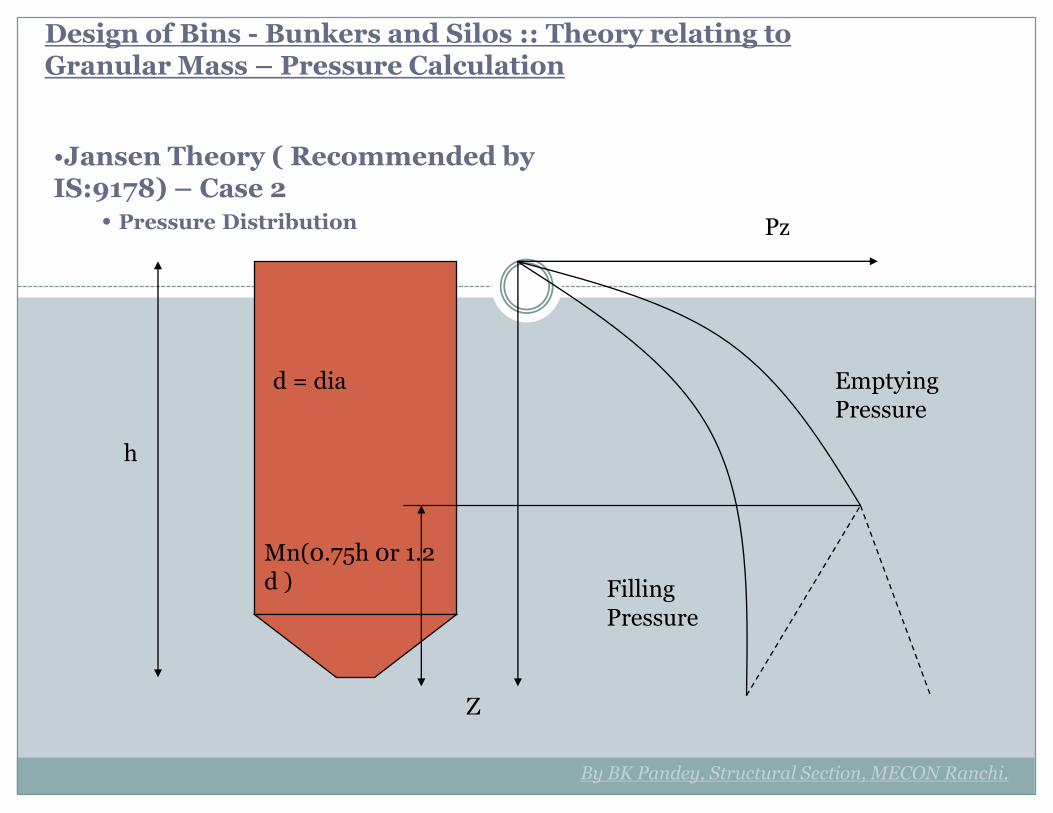
Design of Bins - Bunkers and Silos :: Theory relating to Granular Mass – Pressure Calculation
•Jansen Theory ( Recommended by IS:9178) – Case 2
• Pressure Distribution Pz
Z
h
Filling Pressure
Emptying Pressure
Mn(0.75h 0r 1.2 d )
d = dia
By BK Pandey, Structural Section, MECON Ranchi.
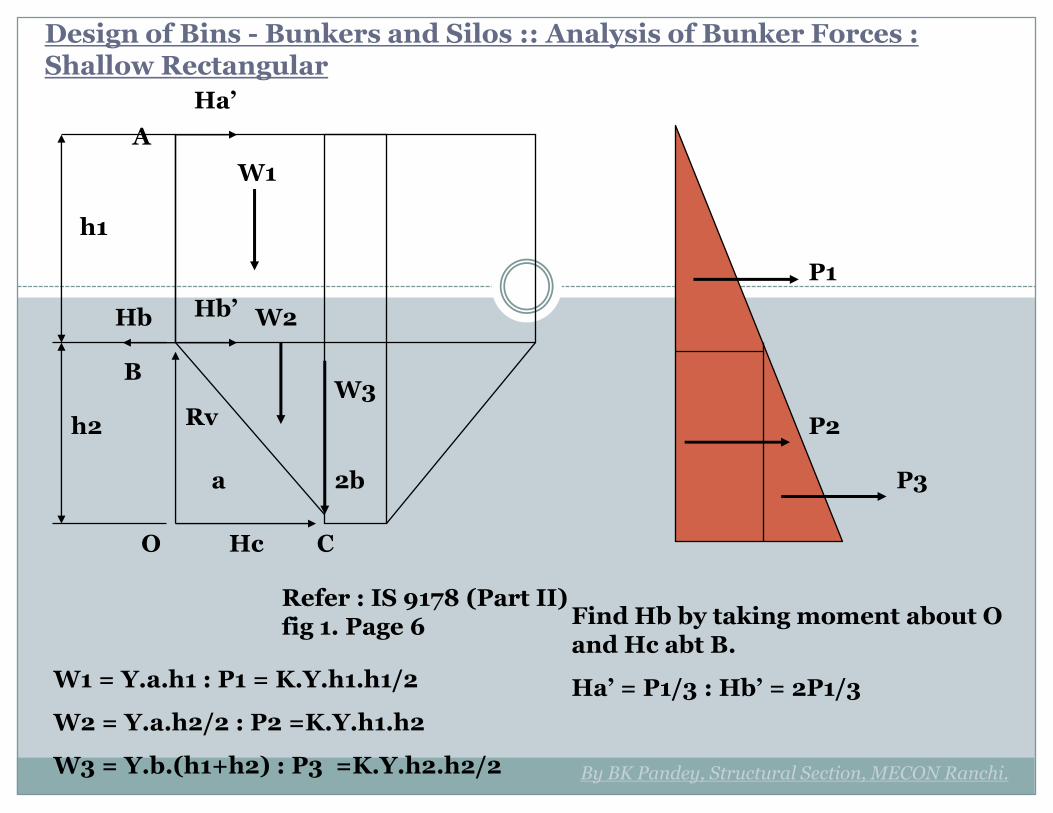
Design of Bins - Bunkers and Silos :: Analysis of Bunker Forces : Shallow Rectangular
W1
W2
W3
P1
Refer : IS 9178 (Part II) fig 1. Page 6
P2
P3
h1
h2
Hc
Hb Hb’
Ha’
A
B
O C
Rv
W1 = Y.a.h1 : P1 = K.Y.h1.h1/2
W2 = Y.a.h2/2 : P2 =K.Y.h1.h2
W3 = Y.b.(h1+h2) : P3 =K.Y.h2.h2/2
a 2b
Find Hb by taking moment about O and Hc abt B.
Ha’ = P1/3 : Hb’ = 2P1/3
By BK Pandey, Structural Section, MECON Ranchi.
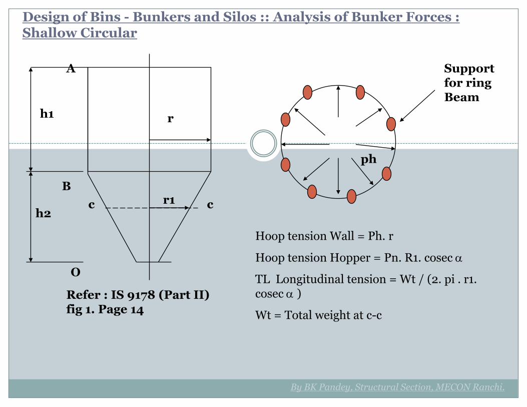
Design of Bins - Bunkers and Silos :: Analysis of Bunker Forces : Shallow Circular
Refer : IS 9178 (Part II) fig 1. Page 14
h1
h2
A
B
O
r1
r
ph
Hoop tension Wall = Ph. r
Hoop tension Hopper = Pn. R1. cosec
TL Longitudinal tension = Wt / (2. pi . r1. cosec )
Wt = Total weight at c-c
c c
Support for ring Beam
By BK Pandey, Structural Section, MECON Ranchi.
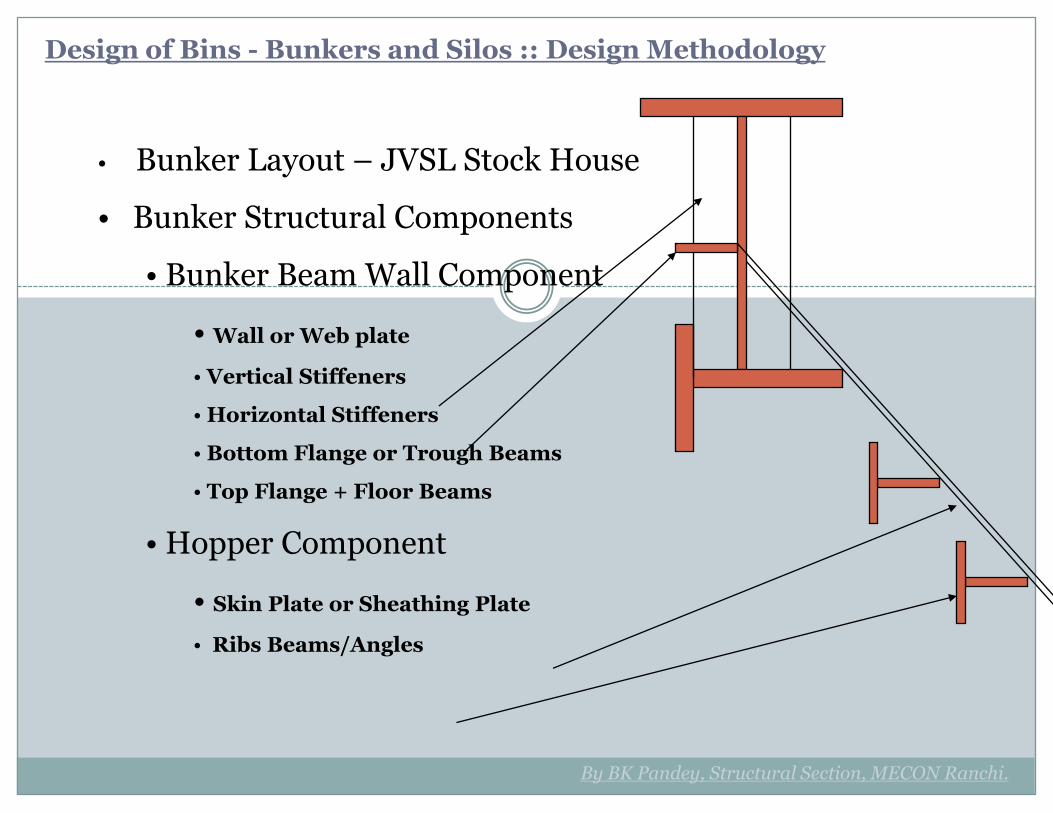
Design of Bins - Bunkers and Silos :: Design Methodology
• Bunker Layout – JVSL Stock House
• Bunker Structural Components
• Bunker Beam Wall Component
• Wall or Web plate
• Vertical Stiffeners
• Horizontal Stiffeners
• Bottom Flange or Trough Beams
• Top Flange + Floor Beams
• Hopper Component
• Skin Plate or Sheathing Plate
• Ribs Beams/Angles