Embed Size (px)
Citation preview
1
Advanced Network Simulation under User-Mode Linux
Andreas Steffen*, Eric Marchionni†, Patrik Rayo†
*Institut für Internet-Technologien und -Anwendungen Hochschule für Technik Rapperswil
Oberseestrasse 10 CH-8640 Rapperswil
†Zürcher Hochschule Winterthur CH-8401 Winterthur
Abstract: The debugging of data communications software in an active networking environment can be a tricky and quite tiresome affair, often so because intermittent disturbances occurring in productive systems cannot be reproduced reliably and consistently or cannot be traced thoroughly enough. Thus for any Linux-based networking appliances like routers, firewalls, intrusion detection systems, VPNs, VoIP gear, etc., the User-Mode-Linux (UML) framework presented in this paper might be the optimum solution for running and testing these systems in a virtual networking environment under near real-time conditions. E.g when a user of the OpenSource Linux strongSwan VPN software reported an IPsec re-keying error occurring in conjunction with a NAT router, this rare problem could be reproduced in a virtual UML test setup within two hours of simulation and a bug fix was found, tested and released on the same day. UML-based networks are also a powerful didactic tool in education where students can gain practical experience with complex network setups without the need of heavy investments in hardware equipment. This paper shows how a UML network can be set up with relative ease either for interactive explorative use or for automated regression testing.
1 Introduction - A Typical Networking Scenario
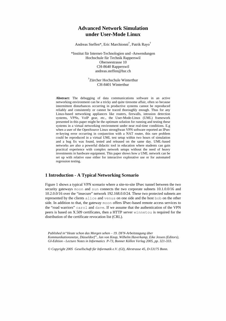
Figure 1 shows a typical VPN scenario where a site-to-site IPsec tunnel between the two security gateways moon and sun connects the two corporate subnets 10.1.0.0/16 and 10.2.0.0/16 over the “insecure” network 192.168.0.0/24. These two protected subnets are represented by the clients alice and venus on one side and the host bob on the other side. In addition to that, the gateway moon offers IPsec-based remote access services to the “road warriors” carol and dave. If we assume that the authentication of the VPN peers is based on X.509 certificates, then a HTTP server winnetou is required for the distribution of the certificate revocation list (CRL).
Published in“Heute schon das Morgen sehen – 19. DFN-Arbeitstagung über Kommunikationsnetze, Düsseldorf”, Jan von Knop, Wilhelm Haverkamp, Eike Jessen (Editors), GI-Edition - Lecture Notes in Informatics P-73, Bonner Köllen Verlag 2005, pp. 321-333. © Copyright 2005 Gesellschaft für Informatik e.V. (GI), Ahrstrasse 45, D-53175 Bonn.
2
Figure 1: A typical VPN scenario comprising a site-to-site tunnel and remote access clients.
Just in order to enact such a relatively simple networking scenario a minimum of eight hardware platforms would be required. The User-Mode-Linux approach presented in this paper will allow us to simulate the whole environment under near real-time conditions by means of eight virtual Linux hosts running on a single hardware box. The only prerequisite is that the services under test are able to run under a Linux operating system.
2 User-Mode-Linux
2.1 User-Mode-Linux Architecture
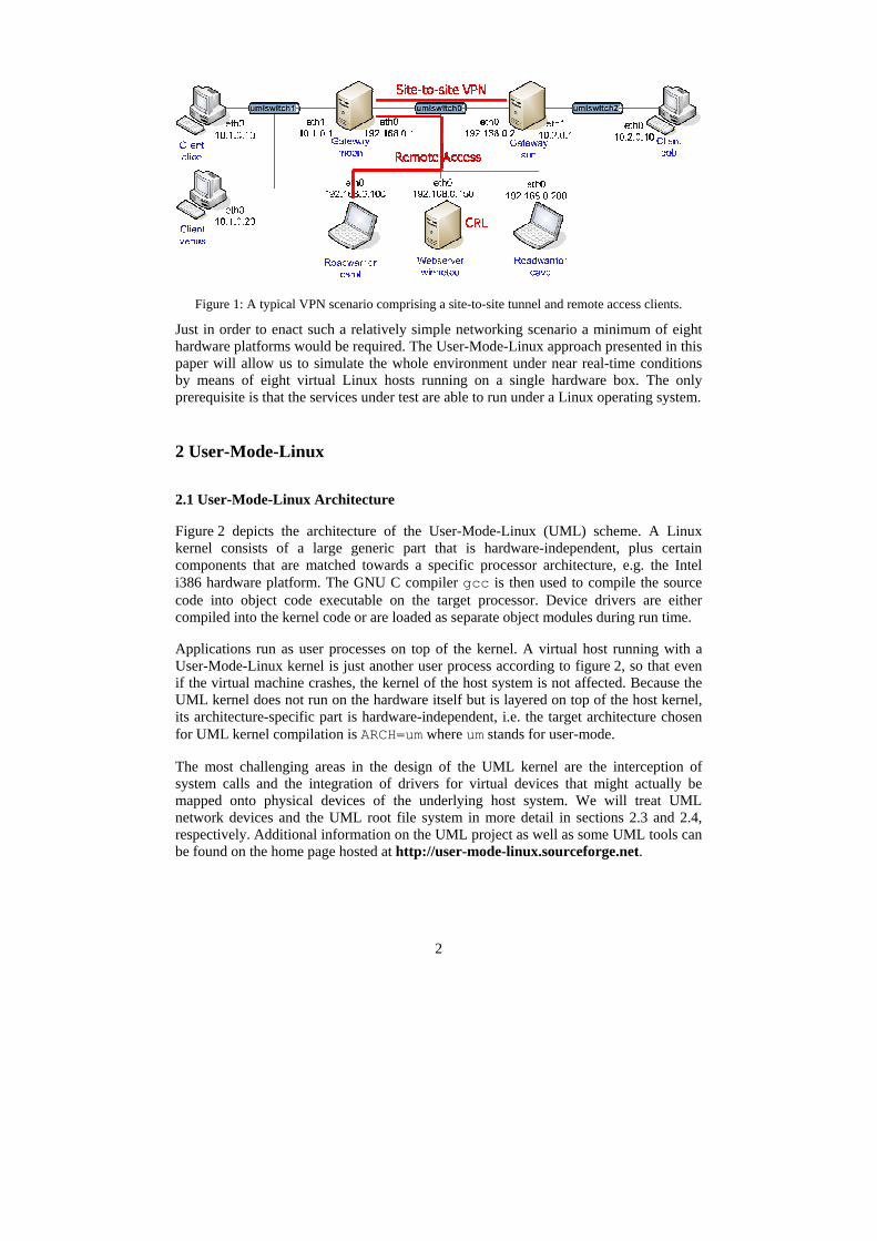
Figure 2 depicts the architecture of the User-Mode-Linux (UML) scheme. A Linux kernel consists of a large generic part that is hardware-independent, plus certain components that are matched towards a specific processor architecture, e.g. the Intel i386 hardware platform. The GNU C compiler gcc is then used to compile the source code into object code executable on the target processor. Device drivers are either compiled into the kernel code or are loaded as separate object modules during run time.
Applications run as user processes on top of the kernel. A virtual host running with a User-Mode-Linux kernel is just another user process according to figure 2, so that even if the virtual machine crashes, the kernel of the host system is not affected. Because the UML kernel does not run on the hardware itself but is layered on top of the host kernel, its architecture-specific part is hardware-independent, i.e. the target architecture chosen for UML kernel compilation is ARCH=um where um stands for user-mode.
The most challenging areas in the design of the UML kernel are the interception of system calls and the integration of drivers for virtual devices that might actually be mapped onto physical devices of the underlying host system. We will treat UML network devices and the UML root file system in more detail in sections 2.3 and 2.4, respectively. Additional information on the UML project as well as some UML tools can be found on the home page hosted at http://user-mode-linux.sourceforge.net.
3
Hardware (e.g. i386)
i386-specific Architecture Drivers
Generic Linux Kernel
Process#1
Process#2 UML Kernel
Process#1
Process#2
User-ModeArchitecture
EmulatedDrivers
Generic Linux Kernel
Hardware (e.g. i386)
i386-specific Architecture Drivers
Generic Linux Kernel
Process#1
Process#2 UML Kernel
Process#1
Process#2
User-ModeArchitecture
EmulatedDrivers
Generic Linux Kernel
User-ModeArchitecture
EmulatedDrivers
Generic Linux Kernel
Figure 2: User-Mode-Linux Architecture.
The versions of the UML kernel and the host kernel do not have to be the same. Thus it is possible to run a Linux-2.6-based UML kernel on top of a Linux-2.4 host kernel or vice versa. Each virtual host instance can run even with its individual UML kernel version.
2.2 SKAS Mode – Separate Kernel Address Space
Traditionally User-Mode-Linux has had the design that each UML process was run as a visible process on the host alongside the UML kernel itself. Thus the UML kernel was present in the address space of each of its processes, and, by default, was writeable. This is obviously a security problem, since, with write access to kernel data, a process can break out to the host. UML's “jail” mode fixes this problem by making UML data read-only while a process is running, but this imposes a huge performance penalty. Also, the kernel is still there, and can be read, so this isn't acceptable for honey pots, since a bad guy can easily tell that the system is a UML.
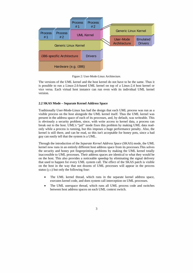
Through the introduction of the Separate Kernel Address Space (SKAS) mode, the UML kernel now runs in an entirely different host address space from its processes.This solves the security and honey pot fingerprinting problems by making the UML kernel totally inaccessible to UML processes. Their address spaces are identical to what they would be on the host. This also provides a noticeable speedup by eliminating the signal delivery that used to happen for every UML system call. The effect of the SKAS patch is visible on the host in the way that not dozens of UML processes will appear in the process status (ps) but only the following four:
• The UML kernel thread, which runs in the separate kernel address space, executes kernel code, and does system call interception on UML processes.
• The UML userspace thread, which runs all UML process code and switches between host address spaces on each UML context switch.
4
• The ubd driver asynchrounous IO thread. • The write SIGIO emulation thread.
SKAS mode requires that a patch must be applied to the host kernel. This patch implements the address space support needed by SKAS mode. The patch is available from www.user-mode-linux.org/~blaisorblade/patches/.
On the UML instance the message Checking for the skas3 patch in the host...found Checking for /proc/mm...found
is going to appear during the booting process if the SKAS mode functionality has been successfully detected in the host kernel.
2.3 UML Network Devices
UML #2UML #2
uml_switchuml_switch
eth0
UML #1UML #1 eth0
tap0 eth0RoutingNAT
RoutingNAT
Host
InternetInternet
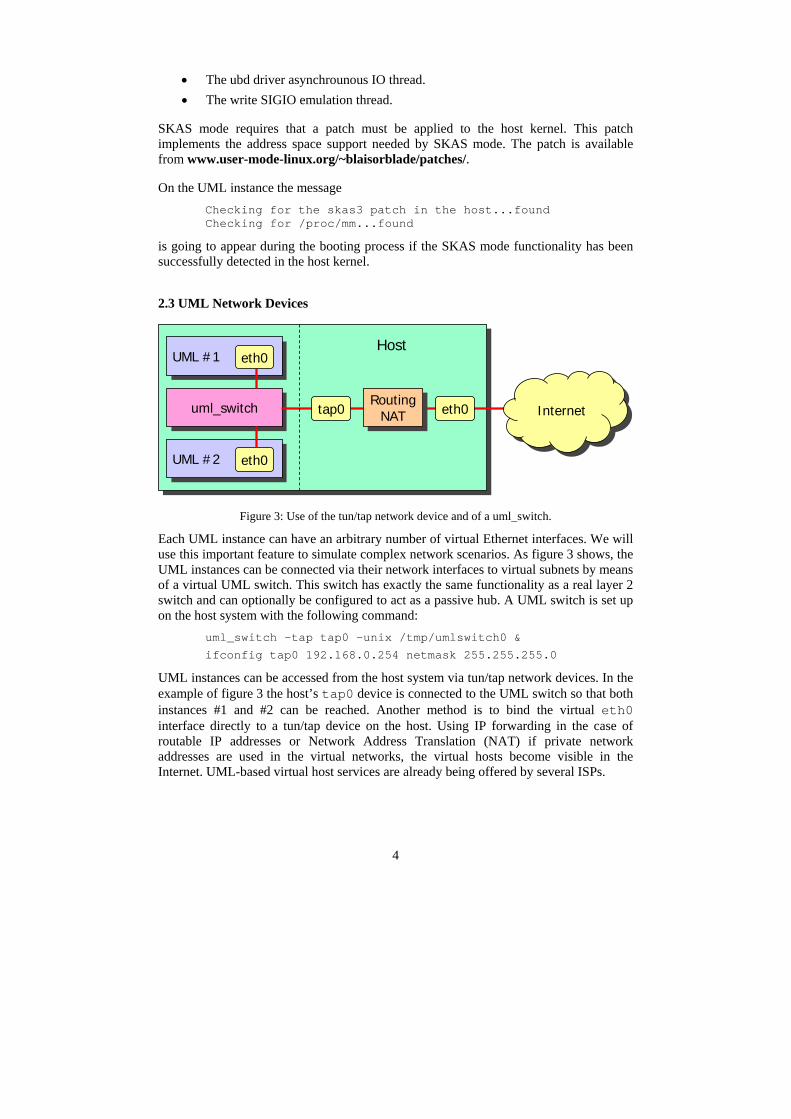
Figure 3: Use of the tun/tap network device and of a uml_switch.
Each UML instance can have an arbitrary number of virtual Ethernet interfaces. We will use this important feature to simulate complex network scenarios. As figure 3 shows, the UML instances can be connected via their network interfaces to virtual subnets by means of a virtual UML switch. This switch has exactly the same functionality as a real layer 2 switch and can optionally be configured to act as a passive hub. A UML switch is set up on the host system with the following command:
uml_switch -tap tap0 -unix /tmp/umlswitch0 &
ifconfig tap0 192.168.0.254 netmask 255.255.255.0
UML instances can be accessed from the host system via tun/tap network devices. In the example of figure 3 the host’s tap0 device is connected to the UML switch so that both instances #1 and #2 can be reached. Another method is to bind the virtual eth0 interface directly to a tun/tap device on the host. Using IP forwarding in the case of routable IP addresses or Network Address Translation (NAT) if private network addresses are used in the virtual networks, the virtual hosts become visible in the Internet. UML-based virtual host services are already being offered by several ISPs.
5
2.4 UML Root File System
Each UML instance uses a root file system of its own that resides as a single large file on the hard disk of the host system. The complete Linux file system contains all required system commands and application programs as well as a sufficient amount of free space to store user data. In principle, a root file system could be shared by several UML instances by using a Copy-On-Write (COW) mechanism where the original files exist only once and just individual modifications and additions are stored separately for each instance at the time they actually occur.
For our network simulation purposes we decided to create a 500 MB root file system for each of the eight virtual instances of the default network topology shown in figure 4. The total disk space requirement on the host system thus amounts to 4 GB. The generic root file system was derived from a standard Gentoo Linux distribution (www.gentoo.org), including among other tools a C compiler (gcc), a debugger (gdb), a network analyzer (tcpdump), a firewall (iptables), secure shell support (ssh, scp) and a web server (apache2). This basic set of system commands and command line tools takes up about 350 MB of the 500 MB root file system, leaving 150 MB for user data.
Since a UML instance runs as a normal user process that can potentially crash and is often terminated improperly e.g. by using the uml_mconsole halt command that just kills the UML process, the use of a robust journaling file system such as reiserfs or ext3 is strongly recommended. Also for reasons of robustness we resigned from using the COW mechanism, giving each instance a root file system copy of its own, instead.
2.4 Starting up a UML instance
In the preceding paragraphs we have described all components that are required to launch a UML instance. The following practical example shall demonstrate how a virtual host is actually started up with a single command line command:
linux-uml-2.6.11 umid=moon \ ubd0=gentoo-rootfs-moon \ eth0=daemon,,unix,/tmp/umlswitch0 \ mem=64M
The executable UML kernel, compiled from the standard Linux 2.6.11 sources with ARCH=um and named linux-uml-2.6.11 is the actual user process that will be started. The UML instance will be named moon, the Gentoo root file system stored in the single large file gentoo-rootfs-moon will be mounted, an eth0 network interface connected to umlswitch0 will be created and 64 MB of RAM will be allocated to the instance.
6
3 strongSwan UML Testing Environment
3.1 Overview
The UML testing environment going to be presented in this chapter was initially created by Eric Marchionni and Patrik Rayo (both recent graduates from the Zürcher Hochschule Winterthur, Switzerland) for the strongSwan OpenSource VPN solution and now makes up the testing part of the software distribution available from www.strongswan.org. Details on their original implementation can be found in the diploma thesis [MR04]. In the following paragraphs the default network topology, the interactive UML simulation mode, as well as the fully automated software regression test mode will be discussed.
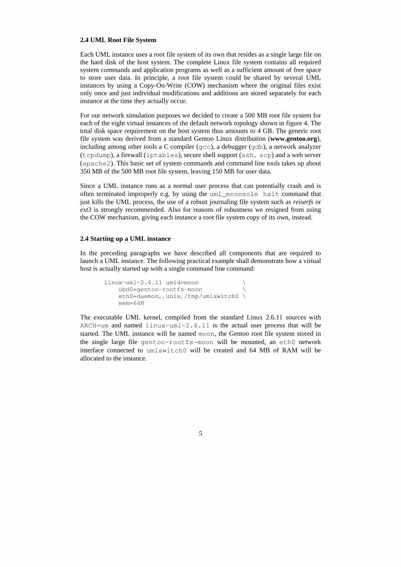
3.2 Default UML Network Topology
Figure 4 shows the default UML network topology created for the strongSwan testing environment. It consists of the eight virtual hosts alice, venus, moon, carol, winnetou, dave, sun, and bob, populating the three separate subnets of the VPN scenario already presented in figure 1, plus three tun/tap devices that connect the host with each of the UML instances via the UML switches sitting at the center of the corresponding sub-networks.
Figure 4: Default UML network topology with 3 networks and 8 UML instances.
7
If not all of the eight hosts are needed for a given simulation scenario then the desired instances can be started by enumerating them on the command line, e.g.
start-testing alice moon carol winnetou
Additional hosts can be added with relative ease either by configuring and starting them manually or by extending the startup-scripts accordingly.
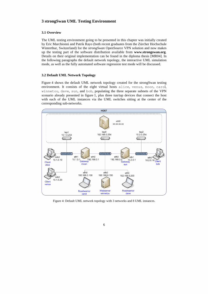
3.3 Interactive Mode
The most flexible way to use the strongSwan UML environment is the interactive mode shown in figure 5. On a graphical desktop either a KDE konsole or an xterm is opened for each started instance. It is also possible to open a terminal console on the host system via remote access and switch between the various UML instances using the screen command.
The interactive mode is ideally suited for the debugging of networked applications because all communication signals exchanged between the hosts as well as all log files and debug information on the hosts are fully available in a controlled environment. By including gcc or any other compiler in the UML root file system, applications can be modified, recompiled and tested on the fly right on the UML instances.
Figure 5: UML network in interactive mode with eight UML consoles and a host window.
8
3.4 Automated Software Regression Tests
For software regression tests that are run prior to each new official software release in order to verify the compliance with the specifications and also to detect bugs in an early stadium, the UML interactive mode is too error prone and too tedious because of the manual configuration steps involved. Therefore as part of [MA04], an automated testing framework was created for the strongSwan IPsec software development environment. This framework can at least in principle be adapted to any software project that requires a networking test bed.
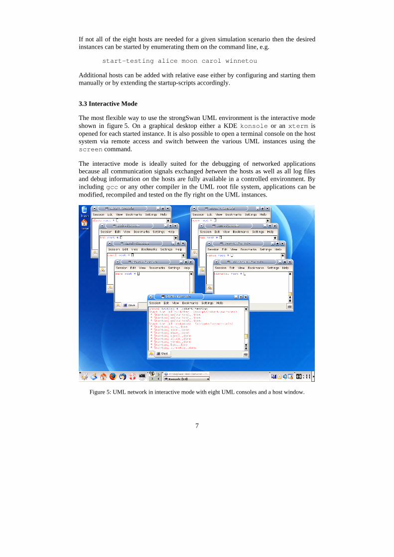
During the creation of the root file systems for the UML instances, the generic Linux base file system (e.g. based on Gentoo or Debian) is supplemented by specific default configurations that are needed by the individual hosts in order to fulfil their particular roles as firewall, router, security gateway, web server, etc. Since most configuration files reside in the /etc/ subtree of a Linux file system and specific services and applications are started via the /etc/init.d/ runlevel mechanism, the current strongSwan framework automatically copies extensions and modifications to the /etc/ subtree on a per-host-basis during the creation of the corresponding UML root file system. The directory structure storing the data used by the configuration scripts is shown in figure 6.
testingtesting
teststests
nat-one-rwnat-one-rw hostshosts
moonmoon etcetc
Specific configurations for test „nat-one-rw“
teststests
nat-one-rwnat-one-rw hostshosts
moonmoon etcetc
Specific configurations for test „nat-one-rw“
hostshosts
defaultdefault etcetc
moonmoon etcetc
Default configuration for all test cases
Configurations common to all hosts
Specific configurations for host „moon“
hostshosts
defaultdefault etcetc
moonmoon etcetc
Default configuration for all test cases
Configurations common to all hosts
Specific configurations for host „moon“
Figure 6: Configuration files for the UML instances.
The default configurations that are put into place by the configuration scripts are also very helpful in the interactive mode, because the applications particular to a given instance can be immediately started and put to use.
9
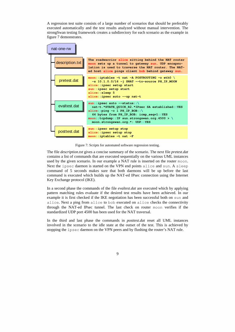
A regression test suite consists of a large number of scenarios that should be preferably executed automatically and the test results analyzed without manual intervention. The strongSwan testing framework creates a subdirectory for each scenario as the example in figure 7 demonstrates.
nat-one-rwnat-one-rw
evaltest.datevaltest.datsun::ipsec auto --status::\nat-t.*STATE_QUICK_R2.*IPsec SA established::YES
alice::ping -c 1 PH_IP_BOB::\64 bytes from PH_IP_BOB: icmp_seq=1::YES
moon::tcpdump::IP sun.strongswan.org.4500 > \moon.strongswan.org.*: UDP::YES
evaltest.datevaltest.datsun::ipsec auto --status::\nat-t.*STATE_QUICK_R2.*IPsec SA established::YES
alice::ping -c 1 PH_IP_BOB::\64 bytes from PH_IP_BOB: icmp_seq=1::YES
moon::tcpdump::IP sun.strongswan.org.4500 > \moon.strongswan.org.*: UDP::YES
posttest.datposttest.datsun::ipsec setup stopalice::ipsec setup stopmoon::iptables -t nat -F
posttest.datposttest.datsun::ipsec setup stopalice::ipsec setup stopmoon::iptables -t nat -F
pretest.datpretest.datmoon::iptables -t nat -A POSTROUTING -o eth0 \-s 10.1.0.0/16 -j SNAT -–to-source PH_IP_MOON
alice::ipsec setup startsun::ipsec setup startalice::sleep 5alice::ipsec auto --up nat-t
pretest.datpretest.datmoon::iptables -t nat -A POSTROUTING -o eth0 \-s 10.1.0.0/16 -j SNAT -–to-source PH_IP_MOON
alice::ipsec setup startsun::ipsec setup startalice::sleep 5alice::ipsec auto --up nat-t
description.txtdescription.txtThe roadwarrior alice sitting behind the NAT router moon sets up a tunnel to gateway sun. UDP encapsu-lation is used to traverse the NAT router. The NAT-ed host alice pings client bob behind gateway sun.
description.txtdescription.txtThe roadwarrior alice sitting behind the NAT router moon sets up a tunnel to gateway sun. UDP encapsu-lation is used to traverse the NAT router. The NAT-ed host alice pings client bob behind gateway sun.
Figure 7: Scripts for automated software regression testing.
The file description.txt gives a concise summary of the scenario. The next file pretest.dat contains a list of commands that are executed sequentially on the various UML instances used by the given scenario. In our example a NAT rule is inserted on the router moon. Next the ipsec daemon is started on the VPN end points alice and sun. A sleep command of 5 seconds makes sure that both daemons will be up before the last command is executed which builds up the NAT-ed IPsec connection using the Internet Key Exchange protocol (IKE).
In a second phase the commands of the file evaltest.dat are executed which by applying pattern matching rules evaluate if the desired test results have been achieved. In our example it is first checked if the IKE negotiation has been successful both on sun and alice. Next a ping from alice to bob executed on alice checks the connectivity through the NAT-ed IPsec tunnel. The last check on router moon verifies if the standardized UDP port 4500 has been used for the NAT traversal.
In the third and last phase the commands in posttest.dat reset all UML instances involved in the scenario to the idle state at the outset of the test. This is achieved by stopping the ipsec daemon on the VPN peers and by flushing the router’s NAT rule.
10
The three phases pretest, evaltest and posttest are controlled by a script running on the host system. The commands are executed on the various UML hosts using the secure shell (ssh), e.g.
ssh root@alice ipsec setup start
At the end of each test a selection of log and status files is copied from the UML instances back to the host system using ssh and scp (secure copy).
3.5 Display of Test Results
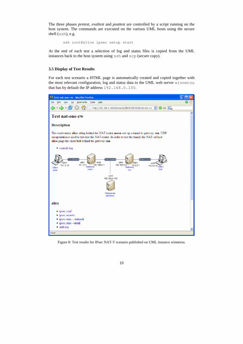
For each test scenario a HTML page is automatically created and copied together with the most relevant configuration, log and status data to the UML web server winnetou that has by default the IP address 192.168.0.l50.
Figure 8: Test results for IPsec NAT-T scenario published on UML instance winnetou.
11
As the sample screen shot in figure 8 shows, all relevant information pertinent to a given test scenario can be conveniently accessed and examined using a standard web browser, without the need to configure a web server on the host system itself. Just do not forget to include winnetou in the list of started UML instances!
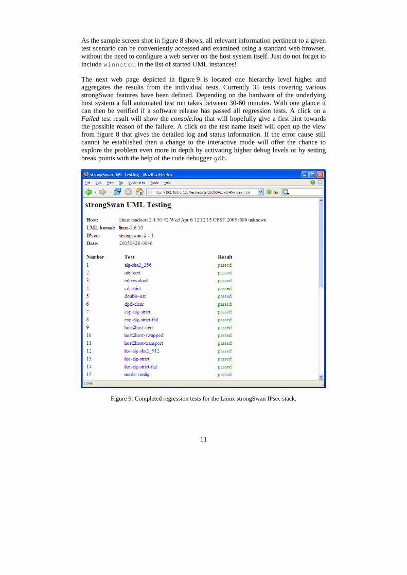
The next web page depicted in figure 9 is located one hierarchy level higher and aggregates the results from the individual tests. Currently 35 tests covering various strongSwan features have been defined. Depending on the hardware of the underlying host system a full automated test run takes between 30-60 minutes. With one glance it can then be verified if a software release has passed all regression tests. A click on a Failed test result will show the console.log that will hopefully give a first hint towards the possible reason of the failure. A click on the test name itself will open up the view from figure 8 that gives the detailed log and status information. If the error cause still cannot be established then a change to the interactive mode will offer the chance to explore the problem even more in depth by activating higher debug levels or by setting break points with the help of the code debugger gdb.
Figure 9: Completed regression tests for the Linux strongSwan IPsec stack.
12
4 Practical Use of UML Networks
4.1 Exploring, Testing and Debugging Network Applications
The example of the strongSwan testing environment presented in the previous chapter clearly shows the manifold advantages of a UML-based test bed. In this section we want to give an overview on several other network applications that would profit significantly from a virtual environment.
VPN Scenarios • NAT-Traversal (RFC 3947) • L2TP-over-IPsec (RFC 3193) • Dead Peer Detection (DPD, RFC 3706) • HTTP or LDAP-based retrieval of Certificate Revocation Lists (CRLs) • Online Certificate Status Protocol (OCSP, RFC 2560) • Simple Certificate Enrolment Protocol (SCEP).
Authentication, Authorization and Accounting (AAA) • Kerberos • RADIUS • IEEE 802.1x port-based network access control • Identity Management scenarios involving LDAP repositories
Firewall Rules and Intrusion Detection • Firewall rules and NAT based on iptables • Port scans using nmap • Network attacks exploiting various vulnerabilities in application programs • Intrusion Detection and Prevention Systems (IDS/IDP, e.g. using snort) • Honey pots
Anonymizing Networks • Pseudo-anonymous remailers • High Latency Anonymizers (Mixmaster, etc) • Low Latency Onion Router networks (Tor available from http://tor.eff.org)
Dynamic Routing Protocols1 • RIP, OSPF, etc
IPv6 Test Beds2 • Mobility for IPv6 (roaming, binding updates, home agents, etc)
1 Since routing networks must possess a certain amount of complexity in order to be non-trivial, a sensible scenario might require an extension of the UML network topology 2 Manual configuration of IPv6 virtual interfaces is possible but UML start-up scripts would need to be extended to support IPv6 addresses.
13
4.2 Education and Training
UML-based networks open up fascinating new opportunities for education and training in the field of IP-based communications technology. Since modern communication protocols have grown quite complex, especially if security aspects are involved and the theory itself is often quite dry, it is of utmost importance that students and trainees can get practical hands-on experience in the communications lab. In a university course the typical size of a lab group is between 16-24 students. Due to the enormous amount of the hardware that would be required to equip all students in a group, it has been difficult and often impossible to set up and test complex networking scenarios during a standard lab session of 2-4 lessons. Also if communications hardware is shared among groups as a cost-saving alternative, many experiments do not scale well with an increasing number of participants. E.g. when experimenting with ARP spoofing attacks, a single group usually succeeds in poisoning the cache of a victim whereas ten concurrent groups just create an abominable chaos.
UML networks running on personal computers do away with the need for a lot of networking hardware and eliminate the traditional stability problems related to equipment being shared by concurrent student groups. The students are given the possibility to explore the given network scenario at their own chosen pace in a confined environment. On the other hand it is possible to connect the virtual setups of each group over the physical lab network thus simulating the establishment of WAN connections.
Starting with the summer term 2005, UML networks have been successfully used in the Internet Security Lab at the Hochschule für Technik Rapperswil (HSR) for setting up and exploring various simple and complex VPN scenarios [Ste03] and also for teaching basic firewall rules working with iptables. The feedback from the students has been very encouraging and led to the decision to extend the UML-based labs to cover more topics.
5 Conclusions
This paper was written with the intention to highlight the manifold opportunities offered by UML-based virtual networks in a communications technology environment. Starting out from the existing strongSwan IPsec testing framework [MR04] developed at the Zürcher Hochschule Winterthur in Switzerland, we have shown that even most complex networking scenarios can be run without any restrictions in near real-time. In our opinion the User-Mode-Linux concept can be easily extended to cover a multitude of other interesting communication setups.
Institutions of higher learning engaged in teaching communications technologies can especially profit both from the increased flexibility and independence that virtual network environments offer to the students, as well as from the considerable savings in hardware investments that can be achieved.
Future areas of work will include research into the use of the new XEN virtualization environment [Ba03] that promises to give a more tight control on consumed resources.

14
Bibliography
[Ba03] Barham, P. et al.: Xen and the Art of Virtualization, SOSP’03, Bolton Landing, New York, 2003.
[MR04] Marchionni, E.; Rayo, P: User-Mode-Linux Test Suite für Linux strongSwan. Diplomar-beit, Zürcher Hochschule Winterthur, 2004.
[Ste03] Steffen, A.: Virtual Private Networks – Coping with Complexity. In (Knop, J. v. Hrsg.): Security, E-Learning, E-Services – 17. DFN-Arbeitstagung über Kommunikationsnetze, Düsseldorf 2003. GI-Edition - Lecture Notes in Informatics (LNI), P-44, Bonner Köllen Verlag, 2003, S. 289-302.