Embed Size (px)
Citation preview

BWS350 Advanced Membrane
Separation SystemInstallation, Operation
& Maintenance ManualRev. 4
Manufactured By:OptiPure a Div. of
AQUION, Inc.2605 Technology Drive, Bldg. 300
Plano, TX 75074P: 972.881.9797 F: 972.422.6262BWS350-iom-manual_v3.indd
©2018 Procam Controls, Inc. All Rights Reserved

BWS350 System Installation, Operation & Maintenance 2
General Information
Safety Warning
Electrical work should be performed by a qualified electrician in accordance with all applicable codes and regulations.
Service Contact
For local maintenance and service information please contact your nearest Authorized Service Representative. Service inquiries may be directed to technical support at:
OptiPure a div. of AQUION, Inc. 2605 Technology Dr. Bldg. 300 Plano, TX 75074 USA Phone #: 972.881.9797 Fax #: 972.422.6262 E-mail correspondence to: [email protected]
Environmental Conditions
The BWS350 is certified to operate under the following conditions:
1. Altitude up to 2000 m.2. Ambient temperature of 40-105°F (5 - 40°C).3. Max relative humidity 80% at 88°F (31°C). 4. Main supply voltage not to exceed +/- 10%.5. Installation category II.6. Pollution degree II.7. Indoor use only, protect from elements.
Explanation of Symbols
The following symbols are used on the water processor. The symbols and their explanation is given below:
Earth ground:
WARNING: Hazardous Voltage:
Safety Instructions
1. Please read and follow these instructions when connecting and using the system.
2. To avoid electrical shock, never touch the
inside of the electrical box. Only a qualified technician should open the electrical box.
3. Never use the system if the power cord or float switch cable has been damaged. Do not allow anything to rest on the power cord or float switch cable, and keep the cords away from any place where people may trip over them.
4. When disconnecting from the electric socket hold the plug, not the cord.
5. If the processor does not function properly, especially if there is an unusual sound or smell coming from it, immediately unplug the processor. Call your authorized service representative.
6. Unplug the processor and RP pump from the AC outlet prior to any service.
7. Locate the RP Assembly as close as possible to an AC outlet.
8. Securely bolt processor to wall before operating.
9. Avoid cross-connections and install on cold water supply only.
10. Use approved Air-Gaps when connecting to drain lines.
11. Do not exceed system pressure rating and use water hammer arrestors when water hammer is evident.
12. Turn off Feed-Water supply before filter or membrane cartridge replacement.

BWS350 System Installation, Operation & Maintenance 3
The BWS350 Advanced Membrane Separation System is designed specifically for users that desire the ability to customize the TDS (Total Dissolved Solids) level or “Mineral Content” of the treated water. The BWS350 utilizes a precision multi-turn Blending Valve to accomplish this with great accuracy. This system design maximizes the ability to accurately blend a calcu-lated percentage of the filtered water with the product water exiting the AMS-QT Membrane, providing an Optimized Water to your equipment with the characteristics that you desire.
Getting To Know Your System
Feed Water Inlet 3/8” Push-To-Connect -
Connect to Water Supply Valve.
CTO-Q (2x)Pre-Filters
Water Quality Indicator - Operates momentarily, push purple button to turn on.
Push “IN” button for the TDS of the water going into your equipment. Push “OUT”
button for the TDS of the purified water from the membrane.
Emergency Bypass Valve - User can switch from Optimized
Water to Untreated Water when needed, by turning handle
horizontal.
Optimized Water To Storage Tank - 3/8” Push-To-Connect - Connect to Optimized Water Storage Tank Inlet
Membrane Reject Water Tubing Connection
AMS-QT Membrane Cartridge
Reject Water Outlet - 1/4” Push-to-Connect - Connect to drain
per local regulations.
1 2 3
Tank Repressurization Return- 1/2” gray hose - Connect to Repressurization Assembly Outlet
Pressurized Optimized Water Outlet - 1/2” gray hose-Connect to End User Equipment
Sample Port -3/8” Push-to-Connect - Used to flush pre filters, gather a water sample, measure pro-duction, or drain water from storage tank.
Blending Valve - Allows precise adjustment of optimized water TDS (mineral content).
120VAC or 230VAC Power Cord- Plug in to standard wall outlet.
Reject Flow Control Valve
Operating Pressure GaugeShows feed pressure only when processor is operating (when level in storage tank is low).
Normal Operation
Items in green circles show a nor-mal operating condition/position.
Optimized Water to Storage Tank Inlet (on Valve) - 3/8” Push-to-Connect - Connect to Opti-mized Water Outlet on Processor.
Absolute 0.2 micronHydrophobic Air-Breather/Filter
Repressurization Assembly Outlet - 1/2” Hose Barb - Connect to Pressurized Water Inlet on Processor
Repressurization Pump 120VAC or 230VAC - Plug in to standard wall outlet
Repressurization Pump
Buffer Tank - Pre-charged air bladder - 20 psi
Optimized Water Storage Tank - 16 gal. Atmospheric
Optimized Water Storage Tank - 50 gal. Atmospheric
Buffer Tank Valve- Normally open (handle parallel to valve body). Used to shut off water supply to downstream equipment.
High Level Float Switch (in Tank) & Cable (on back or side of tank) - Connect Cable to Processor “Tank Electrical Connection.”
Tank Inlet Divert Valve- Normally in Down position. Turn handle to Up position to divert Optimized water to sample port.
Low Level Float Switch (in Tank) - Shuts off pump (using Relay) when tank is empty.
Low Level Relay & Control Box - 120VAC or 230VAC - Plug in cord to standard wall outlet. Box connected to LL Float Switch & Pump. Light on top illuminates when there is water in tank & Pump is enabled.
4
MA-Q15 Mineral Cartridge

BWS350 System Installation, Operation & Maintenance 4
Installation RequirementsThis section and the next provide the water, electrical and space requirements for the BWS350. Pay special attention to the feed-water chemistry requirements. Operating a system on water supplies outside of these parameters may lead to premature membrane failure. This product is for commercial use only and must be installed and maintained in accordance with manufacturer’s guidelines and local regulatory plumbing and electrical codes.
Operating parametersTypical Membrane TDS* rejection: 97+% Feed Temperature: 40 - 100° F (4 - 38° C)Feed pressure: 50 - 80 psi
(3.4 - 5.9 bar) at 1 gpmProduction** (at 77°F, 60 psi) 350 gals/day, 14.6 gals/hr, 0.24 gpm Recovery: up to 33%.
IMPORTANT NOTE: The nominal production rate is strictly dependent on feed water temperature and pressure. Reduced temperature or pressure will reduce production. For example: Operating pressure of 30 psi will cut production by 50%. 48˚F feedwater will cut production by 50%.
LocationThe system should be installed indoors, in the proximity of the equipment (within 25 feet) and protected from the elements. Do not let the processor or storage tank freeze or be exposed to rain or direct sunlight.
Post-treatmentTreated water stored in a tank may absorb organic compounds from the tank, which can affect water taste and odor. If product water is for consumption, an optional post-treatment filter, such as an OptiPure FX or QT carbon filter, should be installed after the tank. If used, it is best installed as close to the point of use as possible. Other specialized post-treatment is also available.
Feed water connectionAn adequate flow and pressure of water to the unit is essential for successful operation. Provide a dedicated 1/2” water line to the vicinity of the installation. Install a full-flow ball valve and pressure gauge with 1/2” female pipe thread (user supplied) for connection to installation hardware provided with the system. A 1/2”
male pipe thread x 3/8” push-to-connect adapter is included in the installation kit. DrainA drain should be located within 5 feet of the location of the unit. Drain must allow a minimum flow of 2 gallons per minute. Compliance with most local plumbing codes requires installation of an approved air gap in the drain line. The drain connection should be accessible for system set-up and service.
Electrical requirementsA power source with two outlets should be located within 5 feet of the location of the unit.
Processor 120V, 6 Mz, 6 Watts or 230V, 50Hz 6 WattsRP Pump 120V, 6 Mz, 2 Amps or 230V 50Hz 2 Amps
Feed-water chemistryFeed TDS Up to 1200 ppmFeed pH 6 - 10Hardness 28 grains or lessFree chlorine <2 mg/lIron (Fe) 0.1 mg/l max.Turbidity <0.05 NTUManganese 0.05 mg/l max.Hydrogen sulfide 0.0 mg/l A water analysis must be conducted before installing the system, or the information requested above can be obtained from your local water utility. If your water analysis shows that any of these parameters are not within range, additional pretreatment and/or higher frequency of maintenance may be required. Contact your OptiPure distributor for assistance. The presence of silica or flocculants such as alum or cationic polymers in the feedwater may cause membrane fouling and may require special chemical pretreatment or periodic membrane cleaning. Please note that membrane failure due to fouling is not covered by the warranty.
Storage TankThe tank must be located within 10 feet of the water processor unit. The floor beneath the storage tank should be smooth, clean and free of sharp objects that could puncture the bottom of the tank. Note: The tank is atmospheric, with a sub-micron, hydrophobic air breather filter.
Optimized Water Lines to EquipmentTubing, piping and associated fittings connecting Optimized water lines to equipment shoud be food grade material that meets NSF Std 51 or 61 with a minimum pressure rating of 75 PSI. Optimized water may react with most metal piping imparting a bad taste. Plastic pipe or reinforced opaque beverage tubing are acceptable choices for Optimized water distribution. The larger inside diameter tubing or hose, the better to minimize pressure drop.
*TDS (total dissolved solids) create conductivity in water and are expressed in ppm or mg/l (parts per million or milligram per liter). System Reject % depends on blended water setting.
**Nominal production @ 77°F (25°C) @ 500 ppm based on a 24 hr day. Actual production will vary based on variations in water temperature, pressure, and TDS.

BWS350 System Installation, Operation & Maintenance 5
Equipment Dimensions
IMPORTANT - ALLOW A MINIMUM OF 24” IN FRONT OF THE PROCESSOR FOR MAINTENANCE AND SERVICE. DO NOT MOUNT SYSTEM ABOVE THE CEILING OR IN A LOCATION THAT IS NOT EASILY ACCESSIBLE. WHEN THE 50 GAL. TANK ASSEMBLY IS FULL OF OPTIMIZED WATER IT WILL WEIGH 450 LBS (THE 16 GAL. TANK, 140 LBS). ALWAYS LOCATE THE STORAGE TANK WHERE IT CAN BE ACCESSED DURING SERVICE.
Allow 3” to remove cartridges
Processor Front View
Processor Left Side View
Optional 175 Gallon Tankwith Repressurization Pump
50 Gallon Tank Repressurization Assembly
16 Gallon Tank Repressurization Assembly
Right Side ViewFront View

BWS350 System Installation, Operation & Maintenance 6
Typical Installation with 50 Gal. Atmospheric TankImportant: Plumbing should be performed by a qualified plumber in accordance with local codes.
Feed Water Line - Green - from Water Supply Valve to Feed Water Inlet
Feed Water
Optimized(Treated) Water toEquipment
Feed Water Inlet
Optimized Water Line - Blue - from Optimized Water Outlet to Tank Inlet
Drain
Lin
e - B
lack -
fro
m Re
ject O
utlet
to Dr
ainReject Water
(to Drain)
User-Supplied Water Supply Valve & Pressure Gauge
Reject WaterOutlet
Tank High Level Float Switch Cable
Optimized Water Outlet to Eqpt
OptionalCarbon Post-Treatment
Power120VAC or 230VAC, 2A
Optim
ized
Wat
er L
ine -
1/2"
Gra
y Hos
e wi
th ho
se ba
rb in
sert
- Mak
e con
necti
on to
dis
tributi
on an
d (op
tiona
l) pos
t-tre
atmen
t.
CTO-
QPr
e-Fi
lter
CTO-
QPr
e-Fi
lter
Emergency Bypass Valve
Operating Pressure
Gauge
Memb
rane
Reje
ct Wa
ter
Tubin
g Con
necti
on
AMS-
QT
Mem
bran
e Car
tridg
e
Water Quality Monitor
1 32
Processor Tank Repressurization Return
Optimized Water
to Storage Tank
Sample Port
Power Cord
When installing, keep lines from the Repres-surization Assembly to the equipment as short as possible to minimize pressure loss.
IMPORTANT - PROTECT PROCESSOR AND REPRESSURIZATION ASSEMBLY FROM THE ELEMENTS. DO NOT INSTALL IN DIRECT SUNLIGHT OR WHERE EXPOSED TO FREEZ-ING TEMPERATURES OR RAIN.
Blending Valve-Set to req'd
TDS reading!
Repressurization Assembly
Optimized Water to Storage Tank Inlet (on valve)
Repressurization Assembly Outlet(Hose Barb)
Optimized Water Storage Tank - 50 gal. Atmospheric
Pressurized Water Line - 1/2" Gray Hose with hose barb inserts at both ends - from Repressurization Assy Outlet to Storage Tank/RP Return
Safety Float Valve(inside tank)
Air Breather
Repressurization Pump
120VAC or 230VACBuffer Tank
Buffer Tank Valve(Normally Open)
Tank Inlet Divert Valve(Valve normally in Down position. Turn to Up position to bypass Repressurization Assy.)
Processor Control High
Level Float Switch
(inside tank)
Byp
ass
Low Level Float Switch(inside tank, with Control Box at-tached to Buffer Tank bracket)
4
MA-Q
15
Mine
ral C
artri
dge

BWS350 System Installation, Operation & Maintenance 7
Wall Mounting
The processor should always be mounted where it is well-supported, either using anchors in a cement wall, or using the support of studs in a wall-board wall. Never mount it directly to sheet-rock alone. Instead, mount it on a sheet of plywood which is anchored to the wall studs, as shown above.
Four user-supplied bolts or screws with a head diameter of approximately 1/2” (which will fit into the keyholes in the system bracket, but will not slip out when tightened) should be used to hang the system.
This will allow the unit to be lifted off the bolts, if necessary for maintenance, without removing all the bolts from the wall. Hold the processor in place
(without the cartridges) to mark the locations for the screws. BE SURE TO ALLOW 3” BELOW THE CARTRIDGES TO ALLOW FOR REMOVAL. Screw the four bolts or screws in place, leaving approximately 1/4” clearance between the bottom of each bolt head and the wall. Position the system over the mounting bolts, and let the bracket slip down into the keyholes. Tighten all screws.
System Installation
Note: Do not install the cartridges in the processor until completing this section. Do not plug in the power cord from the RP pump until completing the following section, “System Start-Up”.
Refer to “Typical Installation” diagram on page 6 and “How to Use Our Quick-Connect
Fittings” on page 20 when making the following connections.
A feed water ball valve and pressure gauge (user supplied) should be installed to provide water to the system FEED WATER INLET with the green tubing (supplied). Hose, tubing and fittings for making connections between the processor, storage tank and drain are supplied in the installation kit.
1. Remove the tank lid. Inside the tank, the float valve may be secured for shipping. Remove any wrapping on the float to allow it to hang and move freely.
2. DRAIN: Connect the 1/4” black tubing from the installation kit to the REJECT WATER OUTLET on the processor. Run the line to an appropriate drain. Observe local plumbing codes and supply an appropriate air gap. (Any fittings for connecting to the drain will need to be supplied by the customer.) Fix tubing in place at the drain.
3. FEED WATER: Apply 3 ‘wraps’ of Teflon tape to the 1/2” FPT x 3/8” push-connect fitting (supplied). Screw the fitting into the Feed Water Supply Ball Valve and tighten (DO NOT OVERTIGHTEN). Connect one end of the 3/8” GREEN TUBING to this fitting. Connect the other end of the tubing to the FEED WATER INLET located on the left side of the Processor. Cut the tubing to the required length if necessary.
Plyw
ood anchored to wall
10.5”
14.7”
8.9”
12.7”
Outside edge of processor bracket
Installation with 16 Gal. Storage Tank
Optim
ized
Wat
er
Line
- Con
nect
to Pr
oces
sor O
ptimi
zed
Wate
r Outl
et
Optimized Water to
Storage Tank Inlet(on Valve)
Repressurization Assembly Outlet
(Hose Barb)
Repressurization Pump
Buffer TankBuffer Tank
Valve(Normally Open)
Optimized Water Storage Tank
- 16 gal. AtmosphericTank Inlet Divert Valve
Refer also to “Typical Installation” Diagram on previous page.
Powe
r Cor
d -to
12
0VAC
or 23
0VAC
Ou
tletPr
essu
rized
W
ater
Lin
e - c
onne
ct to
Pr
oces
sor T
ank
Repr
essu
rizat
ion
Retu
rn
High
Lev
el Sw
itch
Cabl
e-C
onne
ct to
electr
ical b
ox on
lef
t side
of P
roce
ssor
Bypass
Air Breather

BWS350 System Installation, Operation & Maintenance 8
NOTE: When cutting the tubing use a sharp tubing cutter or blade and make a clean, straight cut before inserting into a push-connect fitting. When routing tubing, do not make sharp bends or crimp the tubing.
4. PROCESSOR TO TANK: Connect a piece of the 3/8” blue tubing to the OPTIMIZED WATER TO STORAGE TANK fitting on the processing unit. Connect the other end of this tubing to the OPTIMIZED WATER TO STORAGE TANK INLET on the storage tank INLET DIVERT VALVE.
5. REPRESSURIZATION ASSEMBLY TO PROCESSOR: Using two of the 1/2” hose barb inserts (supplied), a piece of 1/2” gray hose, and two hose clamps, connect hose from the REPRESSURIZATION ASSEMBLY OUTLET on the Repressurization Assembly to the TANK REPRESSURIZATION RETURN on the Processor. The ridged end of a hose barb insert goes into each end of the hose with a hose clamp tightened onto it. The smooth ends of the hose barb inserts go into the push-to-connect fittings on the Processor and Repressurization Assembly.
6. Route the cable coming from the high level switch to the electrical box on the processor. Connect the AMP connector to the TANK ELECTRICAL CONNECTION located on the grey electrical box.
7. OPTIMIZED WATER TO EQUIPMENT: Connect a piece of 1/2” ID gray hose to the OPTIMIZED WATER OUTLET on the processor with a 1/2” hose barb insert and clamp (supplied). At a later time, the other end of this line will be connected to the distribution line that will deliver Optimized Water to the equipment, but for now leave the line loose and route the loose end of the gray hose into a drain or bucket. (Make certain the hose length will reach the storage tank; this will be required for the Start-Up procedure.) Prepare any necessary plumbing to make the connection between the 1/2” hose and the distribution line, which will be completed in “Connect to Equipment”.
NOTE: If Post Filtration is used, it will be installed between the Optimized Water Outlet and the designated equipment.
Optional RP Assembly Location
The Repressurization Pump and Buffer Tank assembly is on a stand that can be remote from the storage tank. If this type of installation is required, the RP Assembly should be built as a remote unit from the OptiPure, with additional installation instructions supplied.
Buffer Tank Valve- Shown in the normal positon
Repressur-ization Assy Outlet
Optimized Water Inlet
Tank Inlet Divert Valve- Shown in the normal positon
50 Gallon Storage Tank
Repressurization Assy Outlet
OptimizedWater Inlet
Tank Inlet Divert Valve - Shown in the normal positon
Buffer Tank Valve- Shown in the normal positon
16 Gallon Storage Tank
BWS350 System Installation, Operation & Maintenance 9
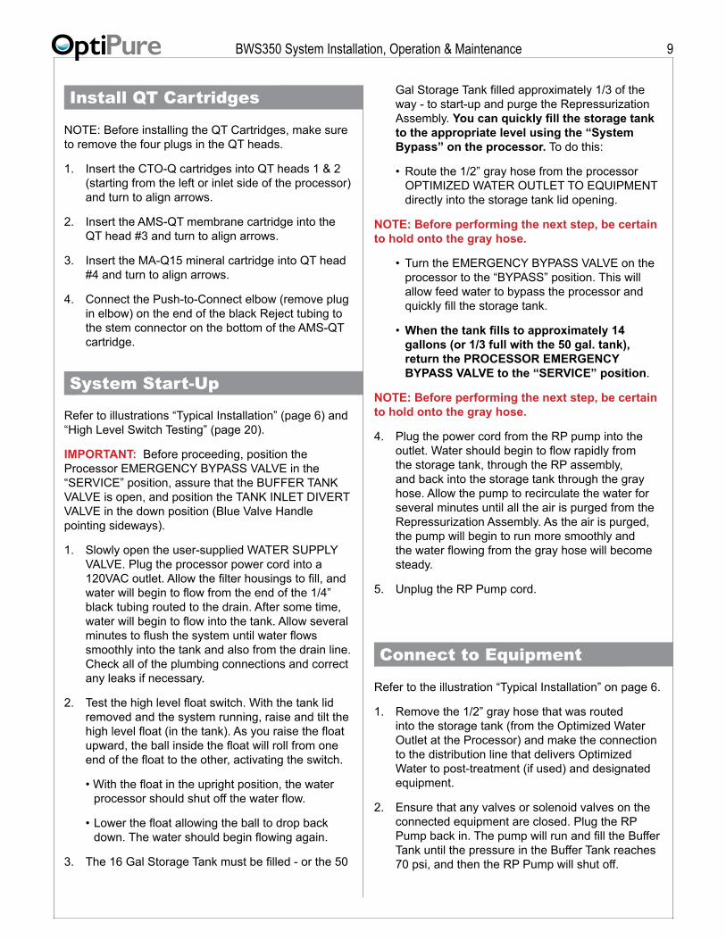
Install QT Cartridges
NOTE: Before installing the QT Cartridges, make sure to remove the four plugs in the QT heads.
1. Insert the CTO-Q cartridges into QT heads 1 & 2 (starting from the left or inlet side of the processor) and turn to align arrows.
2. Insert the AMS-QT membrane cartridge into the QT head #3 and turn to align arrows.
3. Insert the MA-Q15 mineral cartridge into QT head #4 and turn to align arrows.
4. Connect the Push-to-Connect elbow (remove plug in elbow) on the end of the black Reject tubing to the stem connector on the bottom of the AMS-QT cartridge.
System Start-Up
Refer to illustrations “Typical Installation” (page 6) and “High Level Switch Testing” (page 20).
IMPORTANT: Before proceeding, position the Processor EMERGENCY BYPASS VALVE in the “SERVICE” position, assure that the BUFFER TANK VALVE is open, and position the TANK INLET DIVERT VALVE in the down position (Blue Valve Handle pointing sideways).
1. Slowly open the user-supplied WATER SUPPLY VALVE. Plug the processor power cord into a 120VAC outlet. Allow the filter housings to fill, and water will begin to flow from the end of the 1/4” black tubing routed to the drain. After some time, water will begin to flow into the tank. Allow several minutes to flush the system until water flows smoothly into the tank and also from the drain line. Check all of the plumbing connections and correct any leaks if necessary.
2. Test the high level float switch. With the tank lid removed and the system running, raise and tilt the high level float (in the tank). As you raise the float upward, the ball inside the float will roll from one end of the float to the other, activating the switch.
• With the float in the upright position, the water processor should shut off the water flow.
• Lower the float allowing the ball to drop back down. The water should begin flowing again.
3. The 16 Gal Storage Tank must be filled - or the 50
Gal Storage Tank filled approximately 1/3 of the way - to start-up and purge the Repressurization Assembly. You can quickly fill the storage tank to the appropriate level using the “System Bypass” on the processor. To do this:
• Route the 1/2” gray hose from the processor OPTIMIZED WATER OUTLET TO EQUIPMENT directly into the storage tank lid opening.
NOTE: Before performing the next step, be certain to hold onto the gray hose.
• Turn the EMERGENCY BYPASS VALVE on the processor to the “BYPASS” position. This will allow feed water to bypass the processor and quickly fill the storage tank.
• When the tank fills to approximately 14 gallons (or 1/3 full with the 50 gal. tank), return the PROCESSOR EMERGENCY BYPASS VALVE to the “SERVICE” position.
NOTE: Before performing the next step, be certain to hold onto the gray hose.
4. Plug the power cord from the RP pump into the outlet. Water should begin to flow rapidly from the storage tank, through the RP assembly, and back into the storage tank through the gray hose. Allow the pump to recirculate the water for several minutes until all the air is purged from the Repressurization Assembly. As the air is purged, the pump will begin to run more smoothly and the water flowing from the gray hose will become steady.
5. Unplug the RP Pump cord.
Connect to Equipment
Refer to the illustration “Typical Installation” on page 6.
1. Remove the 1/2” gray hose that was routed into the storage tank (from the Optimized Water Outlet at the Processor) and make the connection to the distribution line that delivers Optimized Water to post-treatment (if used) and designated equipment.
2. Ensure that any valves or solenoid valves on the connected equipment are closed. Plug the RP Pump back in. The pump will run and fill the Buffer Tank until the pressure in the Buffer Tank reaches 70 psi, and then the RP Pump will shut off.

BWS350 System Installation, Operation & Maintenance 10
3. Open downstream valves at the equipment to allow water to flow and air to purge through the post-treatment (if used) and from the distribution lines. When purging distribution lines the pump may shut off if the water level in the storage tank drops near the bottom of the tank. (Add more water to the tank if necessary.) Once distribution lines are flushed and all air is purged, close the equipment valves. When there is no demand for water the buffer tank will fill and the pump will shut off automatically.
4. Before proceeding to “System Blend Adjustment,” follow these steps to empty the tank of untreated feed water:
• Connect a piece of 3/8” blue tubing into the push-to-connect fitting of the SAMPLE PORT VALVE on the right side of the processor, and route the other end of the tubing into a drain or bucket.
• Open the Sample Port Valve to drain water from the storage tank. When the pump shuts off due to a low water level, close the Sample Port Valve.
5. Replace and tighten the lid onto the storage tank.
System Blend Adjustment
IMPORTANT: The TDS Blend must be properly adjusted before operating the connected equipment. If you do not know the “TARGET TDS” SET THE BLEND “IN” between 60 and 80. The owner/operator should consult with their OptiPure Dealer or contact the OptiPure factory for assistance in determining an appropriate TDS Target Range.
An improper TDS Blend setting or failure to properly maintain the system can cause damage to equipment. Factors that can impact the TDS of the Optimized Water include changes in water pressure and temperature, seasonal changes in water quality, and municipal source blending practices. To assure maintaining your target TDS range year-round we recommend periodically checking the “IN” TDS and making adjustments as needed.
Optimized Water TDS - Blending Adjustment
1. Allow the system to operate for at least 5 minutes before continuing to Step 2.
2. Push the purple “POWER” button on the Water Quality Monitor located on the upper left corner. It will immediately display the “IN” or Optimized Water - TDS (Total Dissolved Solids) in PPM (parts per million). By adjusting the blend valve you are able to change the “IN” TDS to the desired Target Range.
3. Within 30 seconds, push the “OUT” button to display the Permeate Water TDS (from the RO membrane).
4. If the “IN” TDS is outside of the desired range:
• Turn the Blending Valve knob counter-clockwise to open the Blending Valve, increasing the amount of Filtered Water blending with the RO water, thereby increasing the TDS of the Optimized Water.
• Turn the Blending Valve know clockwise to close the Blending Valve, decreasing the amount of Filtered Water blending with the RO water, thereby decreasing the TDS of the Optimized Water.
5. Once the desired TDS is obtained allow the system to run for several minutes, periodically checking the “IN” TDS. Make smaller incremental adjustments as necessary until the TDS “Target” is achieved.
Complete the Installation
Transition to Owner/Operator
The FINAL STEP is to meet with the Owner/Operator, familiarize them with the system and complete the Post-Installation Check List.
The system is now in “normal operating” mode and the storage tank will fill with Optimized Water from the Processor. Complete the “Post Installation Checklist” to Confirm Normal Operation and System Settings.
Allow the storage tank to fill before beginning operation of the connected equipment.

BWS350 System Installation, Operation & Maintenance 11
Repressurization Pump
The Repressurization Pump Assembly that comes standard with the BWS350 System includes a dia-phragm pump controlled by an internal Pressure Switch, and a Buffer Tank between the Pump and the downstream equipment maintains downstream pres-sure. Water demand for downstream equipment is directly supplied from the Buffer Tank, and demand can go on and off as necessary. The RP Pump is not directly affected by downstream demand, and down-stream equipment is also not affected by the automatic starting or stopping of the RP Pump. When the pres-sure drops sufficiently in the Buffer Tank, the pump starts automatically repressurizes the Buffer Tank. The operating pressure for the RP Pump is preset (to 70 psi) and is NOT field adjustable.
The pump also incorporates check valves to keep the Buffer Tank and downstream line pressurized. The pump is equipped with auto-reset, thermal overload protection and is designed for intermittent duty.
If the pump runs erratically, allow the pump to run to open drain with valve fully open to purge air from the pump head. Disconnect the power and reconnect several times to facilitate air purging.
The pump will prime only if all the pressure is relieved from the outlet port. The pump is self-priming up to 11 ft. The pump can run dry but will overheat and the pump overload will shut the pump off.
Storage Tank Level Controls
(See also the Electrical Schematic at the end of this manual.) For system control, there are independent High and Low Water Level Float Switches in the Storage Tank. When the Storage Tank becomes full, the High Level Float Switch shuts off the Processor, preventing flow to the Tank.
If the tank is empty, the Low Level Float Switch auto-matically shuts off the RP Pump. As long as the power cord from the Tank/RP unit is plugged in, and there is a minimal amount of water in the Storage Tank, the green light is illuminated on the Control Box (attached to the Buffer Tank bracket), indicat-ing that power is supplied to the RP Pump. This light means the RP unit is en-abled, even though the RP Pump may be automatically turned off when the Buf-fer Tank is pressurized and operation of the Pump is not needed.
Low Level Float Switch Indicator light

BWS350 System Installation, Operation & Maintenance 12
BWS350 Processor Components
Green Tubing - Filtered Water LinePN: 580-00111
Red Tubing - Bypass Water LinePN: 580-00104
Black Tubing - Reject Water LinePN: 580-00106
Blue Tubing - Optimized Water LinePN: 580-00110
Bypass Valve -PN: 520-12230
Solenoid Valve -PN: 714-10005
Pressure Gauge -PN: 530-20018
Reject Flow Control -PN: 514-00440
Pressurized Water Check Valve -PN: 524-01035
Sample Port Valve -PN: 520-12223
Permeate Check Valve -PN: 524-01030
Water Quality Monitor -PN: 530-40112
CTO-Q PreFilters (x2) -PN: 300-05830
AMS-QT Cartridge -PN: 204-53040
Stem Connector -PN: 551-65210
Union Elbow -PN: 551-63021
Blending Valve -PN: 514-00442
Electrical Box -w/Tank Connection
MA-Q15 Cartridge -PN: 300-05855

BWS350 System Installation, Operation & Maintenance 13
Tank/RP Components
Tank Bracket -For 16G Storage Tank - PN: 594-80516For 50G Storage Tank - PN: 594-80510
50 Gallon Storage Tank Shown.
16 Gal Storage Tank - PN: 570-0001650 Gal Storage Tank - PN: 570-00056(50 Gal Tank shown.)
Tank Inlet Divert Valve -PN: 520-12225In normal operation, handle should be down (horizontal). For measuring water production or purging air from system, turn Divert Valve handle up.
Float Valve -(inside tank beneath inlet)PN: 520-01203
Air Breather -PN: 300-40005
High Level Float Switch - (inside tank)PN: 740-01120Controls Processor. When tank is full, float switch is in up positon and switch inside float is open, causing Processor to shut off.
RP Pump -PN: 704-35513
Buffer Tank Valve -PN: 520-14501
Optimized Water Inlet -Connect line from Optimized Water Outlet
RP Assy Outlet -1/2” Hose Barb Insert, PN: 550-08730Connect to equipment inlet.
Bypass Check Valve-PN: 524-01030
Foot Valve -(inside tank, at base of pump suction tube)PN: 520-10221
Low Level Float Switch -(inside tank)PN: 740-01116
Low Level Control Relay -(in Control Box)PN: 740-01290
Buffer Tank -For 16G Storage Tank - PN: 340-50001For 50G Storage Tank - PN: 340-50004

BWS350 System Installation, Operation & Maintenance 14
IntroductionThe AMS-QT Reverse Osmosis membrane uses pressure to allow pure water molecules to filter through its semipermeable membrane separating pure water from dissolved solids (salts) and other contaminants. In essence the membrane splits feed water into two separate streams. One stream is the water produced for use (product or pure water), and the other contains the salts and contaminants filtered out by the membrane (reject) carried away to the drain. The OptiPure BWS350 is designed to produce water at a 30% recovery rate which means it uses water at a ratio two gallons of reject water for each gallon of pure water produced. This is a Product/Reject Ratio of 1:2.
The “pure water” produced by the membrane is not always appropriate for use with food service equipment. The BWS350 system also allows blending filtered water with the pure water to produce Optimized Water which can be adjusted to provide the ideal characteristics for foodservice equipment applications. Instructions for blending Optimized water are on page 10.
Each system is adjusted at the factory for the proper operating parameters. In most cases the factory setting should not be changed. However, due to certain conditions an adjustment may produce better operating efficiency and membrane performance. Conditions that can influence the best Product/Reject Flow Rate Ratio include feed water quality (TDS level, Turbidity and specific contaminants such as iron and silica) along with water temperature and water pressure. The
determination of whether to make a Product/Reject Flow Rate adjustment is complex. An understanding of your water chemistry and operating conditions in necessary in order to safely deviate from the factory setting. It is strongly recommended that you contact your OptiPure dealer or the factory for assistance before changing the factory setting.
Reject Flow Rate AdjustmentThe parameter that can be adjusted is the Reject Flow Rate. This is the amount of water used to carry away the impurities rejected by the membrane. It is critical that both the Product Flow Rate and the Reject Flow Rate are measured to confirm the desired Product/Reject Ration has been achieved. The higher the ratio of product to reject flow rate, the shorter the life of the membrane will be.
IMPORTANT: Never close the Reject Flow Control Valve, and never adjust it such that the Reject flow rate is less than the Permeate (Product) flow rate! This will cause premature fouling and shorten membrane life.
To adjust the reject flow rate, locate the reject flow control valve. Loosen the lock-nut (at the base of the valve stem) just slightly.
IMPORTANT: Before adjusting Reject Flow Rate CLOSE the BLENDING VALVE.
To increase the reject flow rate, use a slot screw driver to turn the valve stem counterclockwise. To reduce the reject flow rate, turn it clockwise. A minor adjustment makes a big difference in the flow rate so begin with
Product/Reject Flow Rate Adjustments
Reject Flow ControlAdjust with Blend Valve Closed

BWS350 System Installation, Operation & Maintenance 15
Operating Parameters
Ratio Oper Product/ Temp PRODUCT FLOW RATE REJECT FLOW RATE Reject (°F) (gal/day) (gpm) (L/day) (lpm) (gal/day) (gpm) (L/day) (lpm)
1:2 50 185 0.13 701 0.49 1:2 64 271 0.19 1027 0.71 1:2 77 350 0.24 1325 0.92 700 0.48 2650 1.84 1:2 84 380 0.26 1440 1.00
• The flow rates above are for 60 psi feed pressure. • To convert gallons per minute (gpm) to ounces per minute, multiply gpm by 128.• To convert gallons per minute (gpm) to milliliters per minute, multiply gpm by 3785.
small (1/2 turn) adjustments. After making an adjustment, measure the reject and product water flow rates. Make additional adjustments until the desired Product/Reject Ratio is achieved, then tighten the lock-nut.
Use the “Operating Parameters” table above as a guideline for safe operating flow rates and ratios. This table provides an indication as to how Feed Water temperature affects the Product Water output of the system.
Measuring Product Flow RateConnect a piece of 3/8” tubing to the Sample Port on the right side of the Processor and route it to a bucket or drain. If the tank is full, turn the Sample Port valve to the sample position and allow about 20 gallons to drain out of the storage tank, then close the Sample Port valve. Close the Buffer Tank Valve and turn the Tank Inlet Divert Valve to the divert position (Up). Open the Sample Port valve. While the system is operating in normal mode (Emergency Bypass Valve in Service position), use a graduated cylinder or other measuring vessel to collect and measure the amount of water that is produced (from the tubing connected to the Sample Port) in 60 seconds. To convert ounces per minute to gallons per day, multiply ounces/mn by 11.25.
When finished, close the Sample Port valve, turn the Tank Inlet Divert Valve to the Down position, and open the Buffer Tank Valve.
Measuring Reject Flow RateAccess the Reject Drain Line and perform the same procedure described in “measuring product flow rate.”
Limitations on Adjustment of Reject Flow RateThe factory sets the Product/Reject Ratio to 1:2 with
the Blending Valve closed based on 60 psi Operating Pressure and 77°F which is typically 919 ml per minute +/- 15%. Never close Reject Flow Control Valve nor limit Reject flow to less than Permeate flow!
The AMS-QT membrane is rated for a target daily output of 350 gallons per day of Product Water when the feed water temperature is 77°F and the operating pressure is 60 psi. Do not exceed the rated output of 350 gpd/14.58 gph/0.243 gpm (1,325 liters per day/55.125 liters per hour/919 milliliters per minute). Always keep in mind that feed water temperature and pressure will affect the Product Water output. Depending on feed water pressure and temperature it may not be possible to achieve the rated production of 350 gpd.
Blending Impact on Product/Reject RatioOnce the Blending Valve is opened to blend Filtered Water with the RO Product Water the combined Optimized Water flow rate will be greater than the Product Flow Rate. For example, if the Feed Water TDS is 300 ppm, the AMS-QT product water TDS will be 9 -15 ppm. If your desired Optimized Water TDS is 75 ppm, then you will be adding approximately 13% of the Filtered Water to your RO product water, increasing your Optimized Water flow to a 42% recovery.
In this example your daily Optimized Water Production is approximately 441 gpd at 77°F Feed Water temperature and 60 psi Operating Pressure.
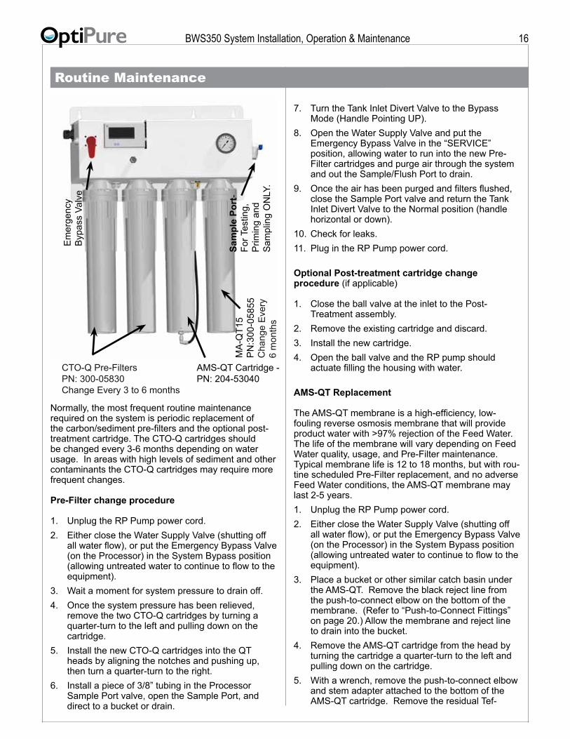
BWS350 System Installation, Operation & Maintenance 16
Normally, the most frequent routine maintenance required on the system is periodic replacement of the carbon/sediment pre-filters and the optional post-treatment cartridge. The CTO-Q cartridges should be changed every 3-6 months depending on water usage. In areas with high levels of sediment and other contaminants the CTO-Q cartridges may require more frequent changes.
Pre-Filter change procedure
1. Unplug the RP Pump power cord.2. Either close the Water Supply Valve (shutting off
all water flow), or put the Emergency Bypass Valve (on the Processor) in the System Bypass position (allowing untreated water to continue to flow to the equipment).
3. Wait a moment for system pressure to drain off.4. Once the system pressure has been relieved,
remove the two CTO-Q cartridges by turning a quarter-turn to the left and pulling down on the cartridge.
5. Install the new CTO-Q cartridges into the QT heads by aligning the notches and pushing up, then turn a quarter-turn to the right.
6. Install a piece of 3/8” tubing in the Processor Sample Port valve, open the Sample Port, and direct to a bucket or drain.
7. Turn the Tank Inlet Divert Valve to the Bypass Mode (Handle Pointing UP).
8. Open the Water Supply Valve and put the Emergency Bypass Valve in the “SERVICE” position, allowing water to run into the new Pre-Filter cartridges and purge air through the system and out the Sample/Flush Port to drain.
9. Once the air has been purged and filters flushed, close the Sample Port valve and return the Tank Inlet Divert Valve to the Normal position (handle horizontal or down).
10. Check for leaks.11. Plug in the RP Pump power cord.
Optional Post-treatment cartridge change procedure (if applicable)
1. Close the ball valve at the inlet to the Post-Treatment assembly.
2. Remove the existing cartridge and discard.3. Install the new cartridge.4. Open the ball valve and the RP pump should
actuate filling the housing with water.
AMS-QT Replacement
The AMS-QT membrane is a high-efficiency, low-fouling reverse osmosis membrane that will provide product water with >97% rejection of the Feed Water. The life of the membrane will vary depending on Feed Water quality, usage, and Pre-Filter maintenance. Typical membrane life is 12 to 18 months, but with rou-tine scheduled Pre-Filter replacement, and no adverse Feed Water conditions, the AMS-QT membrane may last 2-5 years. 1. Unplug the RP Pump power cord.2. Either close the Water Supply Valve (shutting off
all water flow), or put the Emergency Bypass Valve (on the Processor) in the System Bypass position (allowing untreated water to continue to flow to the equipment).
3. Place a bucket or other similar catch basin under the AMS-QT. Remove the black reject line from the push-to-connect elbow on the bottom of the membrane. (Refer to “Push-to-Connect Fittings” on page 20.) Allow the membrane and reject line to drain into the bucket.
4. Remove the AMS-QT cartridge from the head by turning the cartridge a quarter-turn to the left and pulling down on the cartridge.
5. With a wrench, remove the push-to-connect elbow and stem adapter attached to the bottom of the AMS-QT cartridge. Remove the residual Tef-
Routine Maintenance
CTO-Q Pre-FiltersPN: 300-05830Change Every 3 to 6 months
Em
erge
ncy
Byp
ass
Valv
e
Sam
ple
Port
-Fo
r Tes
ting,
P
rimin
g an
d S
ampl
ing
ON
LY.
AMS-QT Cartridge -PN: 204-53040
MA
-QT1
5P
N:3
00-0
5855
Cha
nge
Eve
ry
6 m
onth
s

BWS350 System Installation, Operation & Maintenance 17
Routine Maintenance, Continuedlon tape from the male 1/8” threads on the stem adapter.
6. Wrap the 1/8” male thread on the stem adapter with 2 wraps of Teflon tape and re-install in the bottom of the new AMS-QT cartridge.
7. Align the taps on the AMS-QT cartridge with the QT head and insert into the head and turn a quarter-turn to the right.
8. Insert the black reject line into the push-to-connect elbow on the bottom of the AMS-QT cartridge.
9. Install a piece of 3/8” tubing in the Processor Sample Port valve, open the Sample Port, and direct to a bucket or drain. Turn the Tank Inlet Divert Valve to the Bypass or UP position. Open the Water Supply Valve and put the Emergency Bypass Valve in the “SERVICE” position. Allow water to flush through the membrane, displacing air and preservative, to flow out the Sample/Flush port to drain for 5-10 minutes.
10. Actuate the Water Quality Monitor and check the “OUT” or Permeate Water TDS.
11. After the AMS-QT cartridge is purged of air, close the Sample Port.
12. Check for leaks.13. Plug in the RP Pump power cord.
Storage Tank CleaningIf the Storage Tank becomes dirty, regular cleaning and sanitization may be required. (Request a Storage Tank Cleaning Guide from OptiPure.) The Tank can be
emptied for cleaning by doing the following:1. Close the Water Supply Valve2. Connect 3/8” tubing from the Sample Port on the
Processor to the drain.3. Open the Sample Port. The RP Pump should op-
erate, pumping water to the drain until the Tank is nearly empty.
4. Unplug the RP Pump power cord.5. When finished, close Sample Port, plug in RP
Pump, and open Water Supply Valve.
RP Pump Motor BrushesOver time or with heavy usage, the motor brushes in the RP Pump can become worn, causing the Pump to no longer operate reliably. (See “RP Pump Does Not Turn On” under Trouble-Shooting for symptoms.) For a system with heavy usage, it may be necessary to re-place motor brushes under a preventive maintenance schedule, such as annually. To restore a Pump with worn brushes, order and install Brush Kit 704-39905, which is supplied with instructions.
Buffer Tank Pre-Charge PressureVery slowly over time, the air pre-charge in the RP As-sembly Buffer Tank can diminish, reducing the ability of the Buffer Tank to maintain downstream pressure. Annually, the pre-charge should be checked using a tire gauge on the valve, which is on the side or bottom of the Buffer Tank. If it is lower than 20 psi, air should be added to restore it to 20 psi.
Trouble-Shooting
Problem Possible Cause ResolutionRunning out of water. Valves in incorrect operating position
No power to RP PumpOperating Pressure reducedVery cold Feed Water temperature
Low Feed Water PressureDemand exceeds system capacityHigh Level Float Switch Open
Ensure the Processor Bypass Valve is in Service position, the Repressuriza-tion Assy (RP) Tank Divert Valve is in Down position, & Buffer Tank Valve is Open (handle parallel to valve body).See “RP Pump Does Not Turn On”Pre-Filters need to be replacedRaise water temp to increase production or determine if higher capacity system is requiredInstall optional Feed Water Pressure Booster PumpDetermine if the demand is unusual or inconsistent, or resize systemRemove Storage Tank lid and actuate Float Switch up and down
Poor water quality. Blend Valve mis-adjustedMembrane failure
Follow steps to adjust Blending Valve on Page 10Replace AMS-QT membrane
Short AMS-QT membrane life.
Product/Reject Ratio mis-adjustedPoor Feed Water quality, presence of iron, silica or non-calcium carbonate hardness
Measure and adjust the Reject Flow Rate per Page 15-16Determine Feed Water quality by obtaining a water quality report from city water supply utility or contact your OptiPure dealer
Short Pre-Filter life Heavy sediment loading Add FXAF01-12 or -12B for added Pre-Filter protectionProcessor Either Does Not Shut Off or Turn On
High Level Float Switch or Solenoid Valve not functioning
Remove Storage Tank lid and actuate Float Switch up and down. Replace High Level Float Switch or Solenoid Valve
BWS350 System Installation, Operation & Maintenance 18
Trouble-Shooting, Continued
Water Quality Monitor will not turn on
Dead batteries Replace batteries by sliding Water Quality Monitor up and removing the six screws on the back cover. Remove cover to access battteries.
RP Pump Does Not Turn On
No power to Pump (Green LED Off at top of Control Box - attached to Buffer Tank bracket)
Low water level in Tank (Green LED on Control Box is Off)RP Pump motor brushes worn
RP Pump damaged
If LED is On, RP Pump is operational (Pump will turn on only when the Buf-fer Tank is empty). If LED is Off, ensure power cord is plugged into an outlet with power (check circuit breaker), & that there is water in Tank. If LED will not turn On (with power & water in tank), there may be a problem with Low Level Float Switch or Relay.Allow Processor to partially fill Tank with water. Green LED indicates RP Pump is operational, & will turn on when Buffer Tank is empty.Try bumping the RP Pump with your hand. If it turns on temporarily, the brushes are probably worn. Order & install Brush Kit 704-39905.(Green LED is On, Buffer Tank is empty) If bumping RP Pump yields no response, Pump could be damaged or brushes may still be worn. Call for service.
RP Pump runs intermittently or rough.
Air trapped in pump head.RP Pump motor brushes worn
Unplug pump temporarily and open downstream valve to empty Buffer Tank.See “RP Pump motor brushes worn” above.
RP Pump cycles on-off frequently
Low air pre-charge in Buffer Tank (possible on aged system)
Empty Buffer Tank and re-charge air pressure to 20 psi.
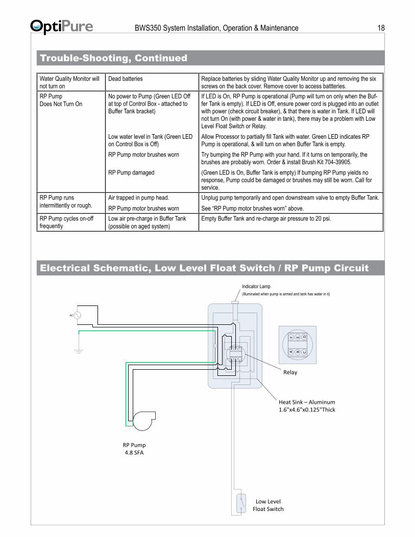
Electrical Schematic, Low Level Float Switch / RP Pump Circuit
AC
RP Pump4.8 SFA
Low Level Float Switch
Heat Sink – Aluminum1.6"x4.6"x0.125"Thick
AF
B CE D
Indicator Lamp(Illuminated when pump is armed and tank has water in it)
Relay
BWS350 System Installation, Operation & Maintenance 19
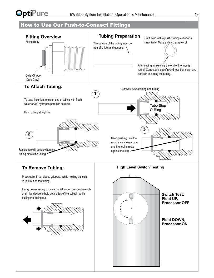
To Remove Tubing:
Press collet in to release grippers. While holding the collet in, pull out on the tubing.
It may be necessary to use a partially open crescent wrench or similar device to hold both sides of the collet in while pulling the tubing out.
To Attach Tubing:
To ease insertion, moisten end of tubing with fresh water or 3% hydrogen peroxide solution.
Push tubing straight in.
Resistance will be felt when the tubing meets the O ring.
The outside of the tubing must be free of knicks and gouges.
Cut tubing with a plastic tubing cutter or a razor knife. Make a clean, square cut.
After cutting, make sure the end of the tube is round. Correct any out of roundness that may have occured in cutting the tubing.
Fitting Overview Tubing PreparationFitting Body
Collet/Gripper(Dark Gray)
Tube StopO-Ring
Keep pushing until the resistance is overcome and the tubing rests against the stop.
1
32
Cutaway view of fitting and tubing
How to Use Our Push-to-Connect Fittings
High Level Switch Testing
Switch Test:Float UP,Processor OFF
Float DOWN,Processor ON