Embed Size (px)
DESCRIPTION
Membrane Separation Technology ppt
Citation preview
7/16/2019 Membrane Separation Technology
http://slidepdf.com/reader/full/membrane-separation-technology-563384db0bc25 1/97
Membrane Separation Processes
Neha Kathayat
Rugved PathareDaksh Pratap Singh
7/16/2019 Membrane Separation Technology
http://slidepdf.com/reader/full/membrane-separation-technology-563384db0bc25 2/97
Overview
Introduction
Ultrafiltration
Reverse Osmosis
Electrodialysis
Summary

7/16/2019 Membrane Separation Technology
http://slidepdf.com/reader/full/membrane-separation-technology-563384db0bc25 3/97
Overview
Introduction
Ultrafiltration
Reverse Osmosis
Electrodialysis
Summary

7/16/2019 Membrane Separation Technology
http://slidepdf.com/reader/full/membrane-separation-technology-563384db0bc25 4/97
Overview
Introduction
Ultrafiltration
Reverse Osmosis
Electrodialysis
Summary
7/16/2019 Membrane Separation Technology
http://slidepdf.com/reader/full/membrane-separation-technology-563384db0bc25 5/97
Overview
Introduction
Ultrafiltration
Reverse Osmosis
Electrodialysis
Summary

7/16/2019 Membrane Separation Technology
http://slidepdf.com/reader/full/membrane-separation-technology-563384db0bc25 6/97
Overview
Introduction
Ultrafiltration
Reverse Osmosis
Electrodialysis
Summary

7/16/2019 Membrane Separation Technology
http://slidepdf.com/reader/full/membrane-separation-technology-563384db0bc25 7/97
Overview
Introduction
Ultrafiltration
Reverse Osmosis
Electrodialysis
Summary

7/16/2019 Membrane Separation Technology
http://slidepdf.com/reader/full/membrane-separation-technology-563384db0bc25 8/97
Introduction
Strathmann defines a membrane as “aninterphase separating two phases and
selectively controlling the transport of materials between those phases”
Since the 1960s a new technology using
synthetic membranes for processseparations has been rapidly developed
7/16/2019 Membrane Separation Technology
http://slidepdf.com/reader/full/membrane-separation-technology-563384db0bc25 9/97
Introduction
Strathmann defines a membrane as “aninterphase separating two phases and
selectively controlling the transport of materials between those phases”
Since the 1960s a new technology using
synthetic membranes for processseparations has been rapidly developed

7/16/2019 Membrane Separation Technology
http://slidepdf.com/reader/full/membrane-separation-technology-563384db0bc25 10/97
Advantages offered
Ambient temperature operation
Relatively low capital and running costs
Modular construction

7/16/2019 Membrane Separation Technology
http://slidepdf.com/reader/full/membrane-separation-technology-563384db0bc25 11/97
Advantages offered
Ambient temperature operation
Relatively low capital and running costs
Modular construction
7/16/2019 Membrane Separation Technology
http://slidepdf.com/reader/full/membrane-separation-technology-563384db0bc25 12/97
Advantages offered
Ambient temperature operation
Relatively low capital and running costs
Modular construction

7/16/2019 Membrane Separation Technology
http://slidepdf.com/reader/full/membrane-separation-technology-563384db0bc25 13/97
General Classification
Most of the membrane processes arepressure driven barring a few like
electro dialysis (ED). Pressure driven process includes micro
filtration (MF), ultra-filtration (UF),reverse osmosis (OS)
Micro filtration, Ultra filtration, Reverse-Osmosis are different with respect topore-size of membrane

7/16/2019 Membrane Separation Technology
http://slidepdf.com/reader/full/membrane-separation-technology-563384db0bc25 14/97
General Classification
Most of the membrane processes arepressure driven barring a few like
electro dialysis (ED). Pressure driven process includes micro
filtration (MF), ultra-filtration (UF),reverse osmosis (OS)
Micro filtration, Ultra filtration, Reverse-Osmosis are different with respect topore-size of membrane

7/16/2019 Membrane Separation Technology
http://slidepdf.com/reader/full/membrane-separation-technology-563384db0bc25 15/97
General Classification
Most of the membrane processes arepressure driven barring a few like
electro dialysis (ED). Pressure driven process includes micro
filtration (MF), ultra-filtration (UF),reverse osmosis (OS)
Micro filtration, Ultra filtration, Reverse-Osmosis are different with respect topore-size of membrane

7/16/2019 Membrane Separation Technology
http://slidepdf.com/reader/full/membrane-separation-technology-563384db0bc25 16/97
Historical Perspective
Following the end of World War II , the USGovt. became concerned about the shortageof water before the end of century.
The US Dept. set up the Office of Saline
Waters (OSW), and committed substantialfinancial resources to the development of various separation processes for waterdesalination, a significant portion of whichwas dedicated to the development of membranes for desalination, continuing thework up to 2 decades.
Result was development of RO and UF and itsno co-incidence that US is the world leaderon this front.

7/16/2019 Membrane Separation Technology
http://slidepdf.com/reader/full/membrane-separation-technology-563384db0bc25 17/97
Ultra filtration
A Pressure Driven
Membrane SeparationProcess

7/16/2019 Membrane Separation Technology
http://slidepdf.com/reader/full/membrane-separation-technology-563384db0bc25 18/97
Membrane Structure and Fabrication
The thin skin on thesurface: usually 0.1 to 1 in thickness.
Permits high hydraulicpermeability
The more open poroussubstructure (typically
120 in thickness)provides goodmechanical support.
Virtually eliminates
internal pore-fouling.

7/16/2019 Membrane Separation Technology
http://slidepdf.com/reader/full/membrane-separation-technology-563384db0bc25 19/97
Today UF membranes are made from
thermally and chemically stable syntheticpolymers like PVC, PAN, polyimides(PI),polysulphone(PS) ,PVDF.
In addition there are inorganic UF
membranes made from zirconium andaluminium oxides.
Plasticizers are necessary for some
membranes, if they are to be dried, toprevent collapse of the pores duringdrying.

7/16/2019 Membrane Separation Technology
http://slidepdf.com/reader/full/membrane-separation-technology-563384db0bc25 20/97
Today UF membranes are made from
thermally and chemically stable syntheticpolymers like PVC, PAN, polyimides(PI),polysulphone(PS) ,PVDF.
In addition there are inorganic UF
membranes made from zirconium andaluminium oxides.
Plasticizers are necessary for some
membranes, if they are to be dried, toprevent collapse of the pores duringdrying.

7/16/2019 Membrane Separation Technology
http://slidepdf.com/reader/full/membrane-separation-technology-563384db0bc25 21/97
Today UF membranes are made from
thermally and chemically stable syntheticpolymers like PVC, PAN, polyimides(PI),polysulphone(PS) ,PVDF.
In addition there are inorganic UF
membranes made from zirconium andaluminium oxides.
Plasticizers are necessary for some
membranes, if they are to be dried, toprevent collapse of the pores duringdrying.

7/16/2019 Membrane Separation Technology
http://slidepdf.com/reader/full/membrane-separation-technology-563384db0bc25 22/97
Modification
Additionalstrength is
provided bycasting themembrane on aspun-bonded
poly-ethylene orpolypropylenebacking.

7/16/2019 Membrane Separation Technology
http://slidepdf.com/reader/full/membrane-separation-technology-563384db0bc25 23/97
Pore Size Determination
UF membranes have “diffuse cut-off” characteristics.
The retention R (in percent) may be definedas ,R = 100 ( 1- ( Cuf / CR ) )
The convention states that the molecular
weight cut-off of the membrane is equal to the molecular weight of the globular proteins which are 90% retained by the membrane .
7/16/2019 Membrane Separation Technology
http://slidepdf.com/reader/full/membrane-separation-technology-563384db0bc25 24/97
Retention Characteristics
1. Size and shape considerations
2. Adsorption losses
3. Charged membranes
4. Pressure effects
5. Temperature effects
7/16/2019 Membrane Separation Technology
http://slidepdf.com/reader/full/membrane-separation-technology-563384db0bc25 25/97
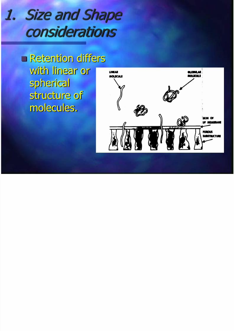
1. Size and Shape considerations
Retention differswith linear or
sphericalstructure of molecules.

7/16/2019 Membrane Separation Technology
http://slidepdf.com/reader/full/membrane-separation-technology-563384db0bc25 26/97
2. Adsorption losses
The polymer which makes the UFaffects the retention if it adsorbs the
species on the membrane surface. Retention of membranes are often
measured in stirred cells.
A mass balance on cell, integrated overtime t .
R = 100 * (ln( Cf / Co ) )/ln( Vo / Vf ))

7/16/2019 Membrane Separation Technology
http://slidepdf.com/reader/full/membrane-separation-technology-563384db0bc25 27/97
3. Charged membrane
Charged UF membrane reject low conc.Of salts, because the fixed chargedgroup on membrane skin reject ionicsolutes via repulsion of co ions.
Obviously, divalent, trivalent ions arerejected better than monovalent ions.
7/16/2019 Membrane Separation Technology
http://slidepdf.com/reader/full/membrane-separation-technology-563384db0bc25 28/97
4. Effect of pressure

7/16/2019 Membrane Separation Technology
http://slidepdf.com/reader/full/membrane-separation-technology-563384db0bc25 29/97
5. Effect of temperature
It has been found experimentally for alarge no.of membranes systems and
feed streams that the permeation rateis inversely proportional to fluidviscosity.
Viscosity of water decreases by 2.5%
for every C rise, researchers refer to3% rule that flux increases 3% per 1 C as rule of thumb.

7/16/2019 Membrane Separation Technology
http://slidepdf.com/reader/full/membrane-separation-technology-563384db0bc25 30/97
Evaluation of Mass Transfer
Co-efficient To evaluate m.t.c, laminar parabolic velocity profileis assumed to be established at the channelentrance
Leveque’s solution gives, Sh = 1.62 ( Re Sc dh / L)0.33
(For 100< (Re Sc dh /L) <5000) Generally, K = .816 (γ D2 /L )0.33
γ = the fluid shear rate at the membrane surface.= 6U/b for rectangular slits.= 8U/d for circular tubes.

7/16/2019 Membrane Separation Technology
http://slidepdf.com/reader/full/membrane-separation-technology-563384db0bc25 31/97
Evaluation of Mass Transfer
Co-efficient To evaluate m.t.c, laminar parabolic velocity profileis assumed to be established at the channelentrance
Leveque’s solution gives, Sh = 1.62 ( Re Sc dh / L)0.33
(For 100< (Re Sc dh /L) <5000) Generally, K = .816 (γ D2 /L )0.33
γ = the fluid shear rate at the membrane surface.= 6U/b for rectangular slits.= 8U/d for circular tubes.

7/16/2019 Membrane Separation Technology
http://slidepdf.com/reader/full/membrane-separation-technology-563384db0bc25 32/97
Evaluation of Mass Transfer
Co-efficient To evaluate m.t.c, laminar parabolic velocity profileis assumed to be established at the channelentrance
Leveque’s solution gives, Sh = 1.62 ( Re Sc dh / L)0.33
(For 100< (Re Sc dh /L) <5000) Generally, K = .816 (γ D2 /L )0.33
γ = the fluid shear rate at the membrane surface.= 6U/b for rectangular slits.= 8U/d for circular tubes.

7/16/2019 Membrane Separation Technology
http://slidepdf.com/reader/full/membrane-separation-technology-563384db0bc25 33/97
UF Plant Design
Mode of operation
The arrangement of membrane moduleand their mode of operation can affectthe economics as much as the moduledesign.
7/16/2019 Membrane Separation Technology
http://slidepdf.com/reader/full/membrane-separation-technology-563384db0bc25 34/97
Applications
Semi conductor industry
Reclamation of waste lubricating oil
Decontamination of crude oil
Waste treatment

7/16/2019 Membrane Separation Technology
http://slidepdf.com/reader/full/membrane-separation-technology-563384db0bc25 35/97
Applications
Semi conductor industry
Reclamation of waste lubricating oil
Decontamination of crude oil
Waste treatment

7/16/2019 Membrane Separation Technology
http://slidepdf.com/reader/full/membrane-separation-technology-563384db0bc25 36/97
Applications
Semi conductor industry
Reclamation of waste lubricating oil
Decontamination of crude oil
Waste treatment

7/16/2019 Membrane Separation Technology
http://slidepdf.com/reader/full/membrane-separation-technology-563384db0bc25 37/97
Applications
Semi conductor industry
Reclamation of waste lubricating oil
Decontamination of crude oil
Waste treatment

7/16/2019 Membrane Separation Technology
http://slidepdf.com/reader/full/membrane-separation-technology-563384db0bc25 38/97
Summarizing U.F
Twenty-five years of invention.
Reliable and economic.
Eliminated severe pollution problems. Recovery of by-products adds to the profit.
Grafting eliminates fouling problems.
Stringent environmental controls may
necessitate UF. Bio-reactors using UF, have tremendous
potential for continuous enzyme reactors.

7/16/2019 Membrane Separation Technology
http://slidepdf.com/reader/full/membrane-separation-technology-563384db0bc25 39/97
Reverse Osmosis
A Pressure Driven
Membrane SeparationProcess

7/16/2019 Membrane Separation Technology
http://slidepdf.com/reader/full/membrane-separation-technology-563384db0bc25 40/97
Osmosis
7/16/2019 Membrane Separation Technology
http://slidepdf.com/reader/full/membrane-separation-technology-563384db0bc25 41/97
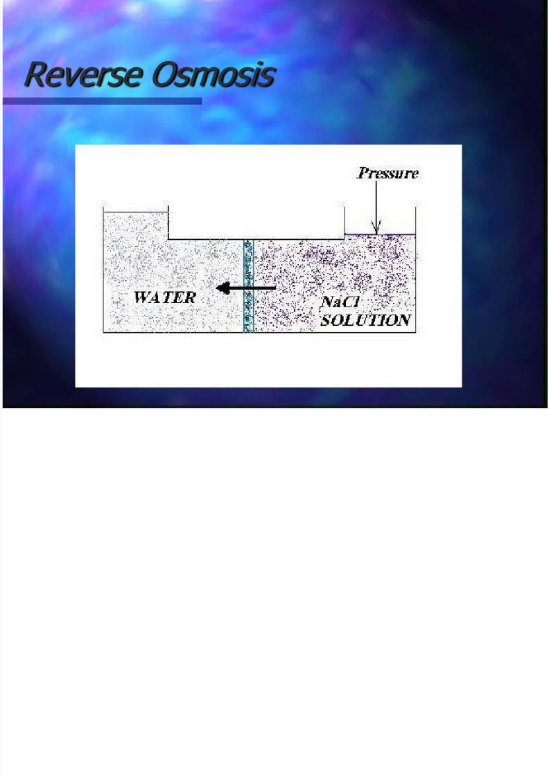
Reverse Osmosis

7/16/2019 Membrane Separation Technology
http://slidepdf.com/reader/full/membrane-separation-technology-563384db0bc25 42/97
R.O membranes
High resolution electron microscopycannot resolve the extensive pore in the
separating layer of the R.O. membranes Therefore it is generally considered that
they do not contain pores and that they
operate mainly by “solution diffusion” mechanism

7/16/2019 Membrane Separation Technology
http://slidepdf.com/reader/full/membrane-separation-technology-563384db0bc25 43/97
Solution diffusion mechanism
Introduced by SOLTANEIH and GILL.
It states that the membrane is non
porous, and that solvent and solutescan only be transported across themembranes by first dissolving in, and
subsequently diffusing through, themembrane

7/16/2019 Membrane Separation Technology
http://slidepdf.com/reader/full/membrane-separation-technology-563384db0bc25 44/97
HAASE and BELFORT model
The solvent flux through the membraneis proportional to pressure gradient:
For the solute it is found that:
)(11 P K J
222 C K J

7/16/2019 Membrane Separation Technology
http://slidepdf.com/reader/full/membrane-separation-technology-563384db0bc25 45/97
Thus, solvent (water) flow occurs onlywhen | ΔP| > |ΔΠ|, solute flow isindependent of | ΔP|
Hence, increasing the operatingpressure increases the effectiveseparation
Typically for brackish water (1.5-2kg/m3 salts), |ΔΠ| = 0.1- 0.7MPa and| ΔP| = 3-8 MPa

7/16/2019 Membrane Separation Technology
http://slidepdf.com/reader/full/membrane-separation-technology-563384db0bc25 46/97
Thus, solvent (water) flow occurs onlywhen | ΔP| > |ΔΠ|, solute flow isindependent of | ΔP|
Hence, increasing the operatingpressure increases the effectiveseparation
Typically for brackish water (1.5-2kg/m3 salts), |ΔΠ| = 0.1- 0.7MPa and| ΔP| = 3-8 MPa

7/16/2019 Membrane Separation Technology
http://slidepdf.com/reader/full/membrane-separation-technology-563384db0bc25 47/97
Thus, solvent (water) flow occurs onlywhen | ΔP| > |ΔΠ|, solute flow isindependent of | ΔP|
Hence, increasing the operatingpressure increases the effectiveseparation
Typically for brackish water (1.5-2kg/m3 salts), |ΔΠ| = 0.1- 0.7MPa and| ΔP| = 3-8 MPa

7/16/2019 Membrane Separation Technology
http://slidepdf.com/reader/full/membrane-separation-technology-563384db0bc25 48/97
Salt rejection
Rejection of ions at R.O membranesdepends on valence
The rejection of organic moleculesdepends on molecular weights

7/16/2019 Membrane Separation Technology
http://slidepdf.com/reader/full/membrane-separation-technology-563384db0bc25 49/97
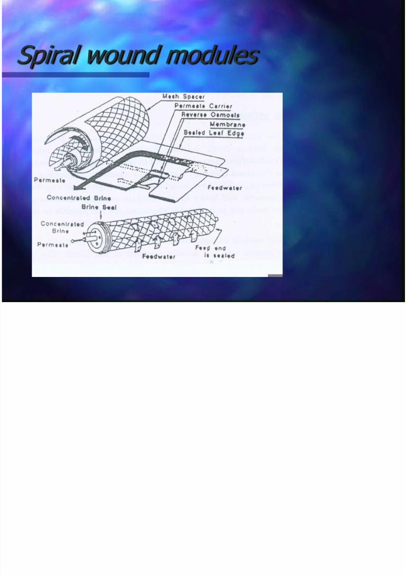
Membrane modules
There are currently four genericconfigurations for membranes inindustrial use :
1. Tubular modules2. Hollow fiber modules3. Flat plate modules
4. Spiral wound modules.

7/16/2019 Membrane Separation Technology
http://slidepdf.com/reader/full/membrane-separation-technology-563384db0bc25 50/97
Tubular module

7/16/2019 Membrane Separation Technology
http://slidepdf.com/reader/full/membrane-separation-technology-563384db0bc25 51/97
Hollow fiber modules

7/16/2019 Membrane Separation Technology
http://slidepdf.com/reader/full/membrane-separation-technology-563384db0bc25 52/97
Flat- sheet module
7/16/2019 Membrane Separation Technology
http://slidepdf.com/reader/full/membrane-separation-technology-563384db0bc25 53/97
Spiral wound modules

7/16/2019 Membrane Separation Technology
http://slidepdf.com/reader/full/membrane-separation-technology-563384db0bc25 54/97
Plant configuration
Batch Recirculation
Feed and Bleed configuration
Continuous Single-pass

7/16/2019 Membrane Separation Technology
http://slidepdf.com/reader/full/membrane-separation-technology-563384db0bc25 55/97
Plant configuration
Batch Recirculation
Feed and Bleed configuration
Continuous Single-pass

7/16/2019 Membrane Separation Technology
http://slidepdf.com/reader/full/membrane-separation-technology-563384db0bc25 56/97
Plant configuration
Batch Recirculation
Feed and Bleed configuration
Continuous Single-pass

7/16/2019 Membrane Separation Technology
http://slidepdf.com/reader/full/membrane-separation-technology-563384db0bc25 57/97
Batch Recirculation

7/16/2019 Membrane Separation Technology
http://slidepdf.com/reader/full/membrane-separation-technology-563384db0bc25 58/97
Feed and Bleed Configuration

7/16/2019 Membrane Separation Technology
http://slidepdf.com/reader/full/membrane-separation-technology-563384db0bc25 59/97
Single pass configuration

7/16/2019 Membrane Separation Technology
http://slidepdf.com/reader/full/membrane-separation-technology-563384db0bc25 60/97
Applications
In some applications the product is theretentate, and the objective is toconcentrate or purify the retained
species and in others the product ispermeate.
Whereas, in some both retentate and
filtrate are important. For example, if avaluable product or by-product is apollutant in a waste stream, recoveryand use of the product will often pay
for pollution abatement.

7/16/2019 Membrane Separation Technology
http://slidepdf.com/reader/full/membrane-separation-technology-563384db0bc25 61/97
R.O. in water treatment
R.O. is a well-established large scaleindustrial process for the desalination of
brackish water More than 1000 units in operation, each
capable of producing 105 m3 /day of
drinking water

7/16/2019 Membrane Separation Technology
http://slidepdf.com/reader/full/membrane-separation-technology-563384db0bc25 62/97
Membranes employed
The two basic membranes employedin in the commercial R.O. systems are
1. The Thin Film Composite (TFC)membranes
2. Cellulose acetate blend (CAB)
membranes
7/16/2019 Membrane Separation Technology
http://slidepdf.com/reader/full/membrane-separation-technology-563384db0bc25 63/97
Membranes employed
The two basic membranes employedin in the commercial R.O. systems are
1. The Thin Film Composite (TFC)membranes
2. Cellulose acetate blend (CAB)
membranes

7/16/2019 Membrane Separation Technology
http://slidepdf.com/reader/full/membrane-separation-technology-563384db0bc25 64/97
Membranes employed
The two basic membranes employedin in the commercial R.O. systems are
1. The Thin Film Composite (TFC)membranes
2. Cellulose acetate blend (CAB)
membranes
7/16/2019 Membrane Separation Technology
http://slidepdf.com/reader/full/membrane-separation-technology-563384db0bc25 65/97
Case Study: R.O at MRL
Objective is to reuse sewage water asprocess water for MRL
Spiral wound module employed.
MRL uses advanced composite membrane(ACM) which is in TFC form.
It is made by first casting the porous
polysulfone film on fabric support. The thin(0.05- 0.2 μ) polyamide membrane is thenformed on the film surface by polymerizationof an aromatic diamine and cycloaliphatictricarbonyl chloride

7/16/2019 Membrane Separation Technology
http://slidepdf.com/reader/full/membrane-separation-technology-563384db0bc25 66/97
Advantages of ACM
Excellent biological stability
Excellent chemical stability except
toward Cl. Resistant to membrane compaction
Longer life as compared to CAB
membranes.

7/16/2019 Membrane Separation Technology
http://slidepdf.com/reader/full/membrane-separation-technology-563384db0bc25 67/97
Advantages of ACM
Excellent biological stability
Excellent chemical stability except
toward Cl. Resistant to membrane compaction
Longer life as compared to CAB
membranes.

7/16/2019 Membrane Separation Technology
http://slidepdf.com/reader/full/membrane-separation-technology-563384db0bc25 68/97
Advantages of ACM
Excellent biological stability
Excellent chemical stability except
toward Cl. Resistant to membrane compaction
Longer life as compared to CAB
membranes.

7/16/2019 Membrane Separation Technology
http://slidepdf.com/reader/full/membrane-separation-technology-563384db0bc25 69/97
Advantages of ACM
Excellent biological stability
Excellent chemical stability except
toward Cl. Resistant to membrane compaction
Longer life as compared to CAB
membranes.

7/16/2019 Membrane Separation Technology
http://slidepdf.com/reader/full/membrane-separation-technology-563384db0bc25 70/97
Thin Film Composites

7/16/2019 Membrane Separation Technology
http://slidepdf.com/reader/full/membrane-separation-technology-563384db0bc25 71/97
Process block diagram

7/16/2019 Membrane Separation Technology
http://slidepdf.com/reader/full/membrane-separation-technology-563384db0bc25 72/97
Pretreatment
R.O almost always requirespretreatment to control fouling
Pretreatment scheme1. Addition of HCl to control pH
2. Addition of SHMP to avoid calciumsulfate scale
3. Micron cartridge filter to removeparticles greater than 10 μ size

7/16/2019 Membrane Separation Technology
http://slidepdf.com/reader/full/membrane-separation-technology-563384db0bc25 73/97
Pretreatment
R.O almost always requirespretreatment to control fouling
Pretreatment scheme1. Addition of HCl to control pH
2. Addition of SHMP to avoid calciumsulfate scale
3. Micron cartridge filter to removeparticles greater than 10 μ size
7/16/2019 Membrane Separation Technology
http://slidepdf.com/reader/full/membrane-separation-technology-563384db0bc25 74/97
Pretreatment
R.O almost always requirespretreatment to control fouling
Pretreatment scheme1. Addition of HCl to control pH
2. Addition of SHMP to avoid calciumsulfate scale
3. Micron cartridge filter to removeparticles greater than 10 μ size

7/16/2019 Membrane Separation Technology
http://slidepdf.com/reader/full/membrane-separation-technology-563384db0bc25 75/97
Pretreatment
R.O almost always requirespretreatment to control fouling
Pretreatment scheme1. Addition of HCl to control pH
2. Addition of SHMP to avoid calciumsulfate scale
3. Micron cartridge filter to removeparticles greater than 10 μ size

7/16/2019 Membrane Separation Technology
http://slidepdf.com/reader/full/membrane-separation-technology-563384db0bc25 76/97
Permeate water characteristics
pH = 7.5
TDS = 400 ppm
Total Hardness as CaCO3= 100ppm
Free ammonia = 0.1 ppm
Nitrates = 1ppm
Silica = 10 ppm
BOD =2ppm COD= 5ppm
total Phosphates = 0.1 ppm

7/16/2019 Membrane Separation Technology
http://slidepdf.com/reader/full/membrane-separation-technology-563384db0bc25 77/97
ACM characteristics
Membrane configuration = spiral wound
Material = polyamide
Supplier = dupont
Dimension= 8” dia x 40” long
Rated operating pressure = 200-350 psig
Temperature range = 0-45oC
pH range = 4-11 Membrane SA = 37.2 m2
Cl tolerance = 0.25 ppm (pH>8) ; 0.1ppm(pH<8)

7/16/2019 Membrane Separation Technology
http://slidepdf.com/reader/full/membrane-separation-technology-563384db0bc25 78/97
Permeate can be used as
Process water
Landscaping, gardening
Ground water discharge for controllingintrusion of sea water into the groundwater table

7/16/2019 Membrane Separation Technology
http://slidepdf.com/reader/full/membrane-separation-technology-563384db0bc25 79/97
Summarizing R.O
Can be widely used as captive wastewater recycle plants in industries
Used for the production of drinkingwater in European countries. Largestsuch plant produces 140000 m3 / daywater for north Paris
In temperate climates nanofiltration ismore economical on this regard.

7/16/2019 Membrane Separation Technology
http://slidepdf.com/reader/full/membrane-separation-technology-563384db0bc25 80/97
Electrodialysis
An electrically driven
membrane separationprocess.

7/16/2019 Membrane Separation Technology
http://slidepdf.com/reader/full/membrane-separation-technology-563384db0bc25 81/97
Flow-diagram for ED

7/16/2019 Membrane Separation Technology
http://slidepdf.com/reader/full/membrane-separation-technology-563384db0bc25 82/97
The membranes
Thin films of polymeric chains containingelectrically charged functional sites.
Anion-exchange membrane (e.g. withquartenary ammonium groups)
Cation-exchange membranes (i.e. withsulfonate groups)
Various methods of producing
Close to 98% efficiency

7/16/2019 Membrane Separation Technology
http://slidepdf.com/reader/full/membrane-separation-technology-563384db0bc25 83/97
ED Stack
1: Polypropylene end plate 2: Electrode 3: Electrode chamber 4: spacer-sealing PVC 5: Spacer fabric 6: Screws 7: Steel frame 8: Inlet anode cell 9: Inlet concentrate cell 10: cation exchange membrane
11: AAM 12: Inlet diluate cell 13: Inlet cathode chamber

7/16/2019 Membrane Separation Technology
http://slidepdf.com/reader/full/membrane-separation-technology-563384db0bc25 84/97
Process configurations
7/16/2019 Membrane Separation Technology
http://slidepdf.com/reader/full/membrane-separation-technology-563384db0bc25 85/97
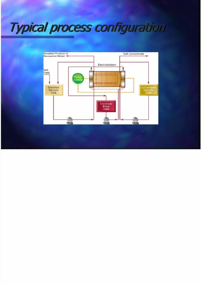
Typical process configuration

7/16/2019 Membrane Separation Technology
http://slidepdf.com/reader/full/membrane-separation-technology-563384db0bc25 86/97
Typical Applications
Demineralization
Concentration of electrolytes
Ion-replacement reactions
Metathesis reactions
Separation of electrolysis products
Fractionation of electrolytes

7/16/2019 Membrane Separation Technology
http://slidepdf.com/reader/full/membrane-separation-technology-563384db0bc25 87/97
Electrodialysis reversal (EDR)

7/16/2019 Membrane Separation Technology
http://slidepdf.com/reader/full/membrane-separation-technology-563384db0bc25 88/97
Cation-neutral ED
7/16/2019 Membrane Separation Technology
http://slidepdf.com/reader/full/membrane-separation-technology-563384db0bc25 89/97
Limiting current density
Transference number is the fraction of current carried by an ion
t+
for cations and t-
for anions ts
- for anion through solution (say .5)
tm- for anion through anion exchange
membrane (say 1.0)
So at membrane there is a depletionlayer set up

7/16/2019 Membrane Separation Technology
http://slidepdf.com/reader/full/membrane-separation-technology-563384db0bc25 90/97
Contd…
At a certain current theconc. becomes 0
This is called limiting
current density Beyond this H+ and OH-
is transported acrossthe membrane
Loss of efficiency andppt of salts due to pHchanges
Ilim= limiting currentdensity
D= diffusion coefficient
F= Faraday’s const.
l=Equivalent filmthickness
)(
lim
smi t t l
DF
zC
i

7/16/2019 Membrane Separation Technology
http://slidepdf.com/reader/full/membrane-separation-technology-563384db0bc25 91/97
Typical process configuration

7/16/2019 Membrane Separation Technology
http://slidepdf.com/reader/full/membrane-separation-technology-563384db0bc25 92/97
Typical Applications
Demineralization
Concentration of electrolytes
Ion-replacement reactions Metathesis reactions
Separation of electrolysis products
Fractionation of electrolytes

7/16/2019 Membrane Separation Technology
http://slidepdf.com/reader/full/membrane-separation-technology-563384db0bc25 93/97
Electrodialysis reversal (EDR)
Deals with fouling of the membrane andscale formation
Reversal of polarityseveral times anhour along withalternation of conc.
and demin stream Useful with Ni, Zn,
Fe salts etc

7/16/2019 Membrane Separation Technology
http://slidepdf.com/reader/full/membrane-separation-technology-563384db0bc25 94/97
Variations of ED
Cation exchangeand neutralmembrane
Elimination of anionmembrane
Greater flexibility inselecting flow rates
and feed and o/pconc
Electrosorption
Neutral inner layerbetween a cation ex
membrane andanion ex membrane
During normaloperation the
neutral gets loadedand in reverse getsunloaded

7/16/2019 Membrane Separation Technology
http://slidepdf.com/reader/full/membrane-separation-technology-563384db0bc25 95/97
Compact water purification electrodialysis units are connected directly to themain water supply system through a flexible hose.
The pressure of 1 –3 atm is quite sufficient,because their operating pressure is within 0.3 –0.4atm. Thus, in comparison with RO there is no need of additional pump of high pressure;
as a result there is another main advantage:consumers have the opportunity to regulate themselves the taste of water by means of a simpleturn of the tap;
residual chlorine in water does not influence thedesalination process, therefore there is no need of cartridges before treatment;
simplicity and slight adjustment of the process,low power consumption and low cost of units promises a great advantage in the future;
when using these units there is no need of
bottle water purchase.

7/16/2019 Membrane Separation Technology
http://slidepdf.com/reader/full/membrane-separation-technology-563384db0bc25 96/97
Seawater desalination with ED

7/16/2019 Membrane Separation Technology
http://slidepdf.com/reader/full/membrane-separation-technology-563384db0bc25 97/97
Comparison of RO and ED