Embed Size (px)
Citation preview

RUSS COLLEGE OF ENGINEERING AND TECHNOLOGY
Advanced Integrated Technologies for Treatment and Reutilization of Impaired Water in Fossil Fuel-based Power Plant Systems
Thursday April 21st, 2016David Ogden (OHIO), Xiujuan Chen (WVU), Xingbo Liu (WVU), and Jason Trembly (OHIO)
Institute for Sustainable Energy and the Environment
1

RUSS COLLEGE OF ENGINEERING AND TECHNOLOGYInstitute of Sustainable Energy and the Environment
Institute for Sustainable Energy and the Environment (ISEE)Institute Facts• Established in 2004• Faculty: 3• Staff: 5 (Engineers and scientists)• Graduate Students: 12• Undergraduate Students: 14• Space: 14,000 ft2
Core Capabilities• Thermocatalytic Processes• Process Engineering & Design• Process Modeling & Simulation
2
ISEE R&D
Coal
Water
Oil/Gas
Biomass
• Algae growth/conversion
• Thermocatalyticconversion
• Coal conversion (syngas & pyrolysis)
• CO2 utilization• Solid oxide fuel cells
• Nutrient recovery• Acid mine drainage• NORM removal• Hydrocarbon removal
• Wastewater management• Electrochemical
conversion• SAGD operations• Fracturing simulation
Home to Two Ohio Third Frontier Technology
Commercialization Centers

RUSS COLLEGE OF ENGINEERING AND TECHNOLOGYInstitute for Sustainable Energy and the Environment
Project Specifics and Team
3
Project Specifics• DOE/NETL Cooperative Agreement No.
DE-FE0026315• DOE Project Manager: Barbara Carney• Principal Investigator: Jason TremblyProject Funding• DOE Funding: $750,000• Cost Sharing: $187,500Period of Performance• September 1, 2015 to February 28, 2017
OHIO Project Team•Project Management
•Jason Trembly (OHIO)•Process Development
•Xingbo Liu (WVU)•David Ogden (OHIO)•Wen Fan (OHIO)•Shyler Switzer (OHIO)•Graduate Student(s)
•Process Engineering•Dora Lopez (OHIO)•Matt Usher (AEP)

RUSS COLLEGE OF ENGINEERING AND TECHNOLOGYInstitute for Sustainable Energy and the Environment
Water-Energy Constraints
U.S. Water Supply • Critical to U.S. energy/economic security • Major constraints
– Increasing population– Increasing energy production– Competing demands– Climate change
• Power generation – Withdraws 950-2,700 M/bbl daily– Consumes 45-90 M/bbl daily– Fresh water supply geographically dependent
• East of Mississippi River: Surface water• West of Mississippi River: Ground water
– Contributes to stress on nearly 100 U.S. watersheds
4
Energy Production Accounts for 80% of Industrial Use

RUSS COLLEGE OF ENGINEERING AND TECHNOLOGYInstitute for Sustainable Energy and the Environment
Power Plant Water RequirementsPower Plant Makeup Water Requirements1
5
Cooling Tower
FGD Installation
1. NETL, 2009.
Unit Operation Subcritical PC Supercritical PC
Cooling Tower -440 gal/MWh 385 gal/MWh
Flue Gas Desulfurizer (FGD) ~70 gal/MWh ~60 gal/MWh
Boiler Feedwater ~10 gal/MWh ~10 gal/MWh
Total ~520 gal/MWh ~455 gal/MWh
• Advanced Cycles• IGCC (Slurry fed): 310 gal/MWh • NGCC: 190 gal/MWh
CCS Addition Increases Water Makeup Requirements by 50-90%

RUSS COLLEGE OF ENGINEERING AND TECHNOLOGY
Makeup Water Considerations• Water chemistry• Volume• Process considerations
– Scaling– Corrosion– Biofouling
Institute for Sustainable Energy and the Environment
Power Plant Makeup Water
6
Makeup Water Quality GuidelinesConstituent FGD Circulation
WaterBoiler
Feedwater pH 6.0-9.0 6.8-7.21 9.3-9.6
SO42- (mg/L) 300 147,200 0
Cl- (mg/L) 100-110 - 0Fl- (mg/L) 2 - 0
Fetotal (mg/L) 2 <0.5 <.01Ca2+ (mg/L) 100-150 900 0Mg2+ (mg/L) 30-50 - 0Na+ (mg/L) 75-125 - 0.003-0.005
HCO3- (mg/L) 150-200 30-2501 0
Mn2+ (mg/L) - <0.5 0Al3+ (mg/L) - <1 0Cu2+ (mg/L) - <0.1 <0.002NH4
- (mg/L) - <2 <0.02SiO2 (mg/L) 10-50 150 0TDS (mg/L) 500-1,000 70,000 <.05Mg x SiO2 - 35,000-75,000 0
TSS (mg/L) 200-300 100-300 0Turbidity (NTU) 200-2,000 - 0
Conductivity (µS/cm) 500-1,000 - 0.5, Max.Hardness (mgCaCO3/L) 200-300 500,000 0
Oil & Grease 0 0 0

RUSS COLLEGE OF ENGINEERING AND TECHNOLOGYInstitute for Sustainable Energy and the Environment
Proposed Impaired Water Treatment Process
• Technologies– UV Treatment– NORM Absorption (Produced water)– Electrochemical Removal
• Minor constituent removal (Fe2+/Fe3+, Mn2+, Ru2+, Zn2+, and Cu2+)
– Selective precipitations• Minor constituents (Ba2+ and Sr2+)
– SCW Treatment• Bulk constituents
7
Proposed Impaired Water Treatment Process

RUSS COLLEGE OF ENGINEERING AND TECHNOLOGYInstitute for Sustainable Energy and the Environment
Project Schedule and Tasks
8

RUSS COLLEGE OF ENGINEERING AND TECHNOLOGYInstitute for Sustainable Energy and the Environment
Project Objectives
9
Overall• Develop a site deployable cost-effective technology for treating impaired water generated from CO2
storage operationsSmall Scale Testing• Validate technical and commercial feasibility of new internally heated SCW treatment methodology for
removal of major constituents from impaired water• Determine effectiveness of electrochemical stripping to remove minor constituents from impaired water• Determine effectiveness of corrosion resistant coatings to improve SS performance in high chloride
content waterProcess Engineering• Identify process configurations which maximize constituent removal, optimize heat integration, and
minimize water treatment costs• Prepare scope for implementing the SCW-based impaired water treatment for a pilot scale effort• Identify best suited power plant makeup water applications for treated water product

RUSS COLLEGE OF ENGINEERING AND TECHNOLOGY
Preliminary Electrocoagulation
Results10

Major steps:
1) Anodic oxidation and cathodic reduction;
2) Generation of coagulants;
3) Precipitation of pollutants on coagulants;
4) Separation by flotation with generated H2.
Electrocoagulation Process
A.K. Golder, A.N. Samanta, S. Ray. Journal of Hazardous Materials 141 (2007) 653–661

Electro-Coagulation Process
A.K. Golder, A.N. Samanta, S. Ray. Journal of Hazardous Materials 141 (2007) 653–661
Major Objectives Maximize removal efficiency Kinetic assessment: minimize energy consumption while maintaining higher
removal efficiency Assess EC process mechanism: (absorption, co-precipitation, surface
complexation or electrostatic attraction)
Efficiency Considerations Electrode materials and arrangement Distance of the electrodes Conductivity of wastewater Initial pH Current density and EC time

Note: If water electrolysis is the only favorable reaction, the bulk pH would remain constant,due to equimolar production of H+ and OH-.
• Generally, the solution pH (pHf) increased atthe end of EC process due to OH- generation.
• Metals ions still consuming OH-.
Preliminary Results

Preliminary Results Table1 Initial and residual metal concentration, metal removal (%), residual concentration of anode ion after
Al EC and Fe EC process. Control sample (marked with red lines) was obtained after 30 min of Al EC at
initial pH 4.6, electrode distance of 10mm.

Preliminary Results
Metal ions Samples Current density (mA/cm-2)pH Removal (%) Residual anode ions (mg/l)
pHi pHf Ba2+ Ca2+ Mg2+ Sr2+ Al3+
Ba2+,Ca2+,Mg2+,Sr2+ Sample 1 4.2 5.8 4.63 5.9 9 36 0 18.44Al electrode Sample 2 8.4 5.75 4.77 4.7 5.8 25 0.5 38.32
Ba2+,Ca2+,Mg2+,Sr2+Sample 3 4.2 pHi pHf Ba Ca Mg Sr Fe
Fe electrode 5.75 4.46 11.2 4.7 11.7 0 6.2
Table 2 Metal removal (%), residual concentration of anode ion after 30 min Al EC and Fe EC process. With
electrode distance of 10 mm.

1) The optimum current density for this case is not located in the range of 0.1-0.2A;
2) Acceleration of EC process is possibly unfavorable for the removal of these metal ions.
3) In this case, Fe-electrode is more efficient than Al-electrode.
4) Different removal mechanisms for Ba2+, Ca2+, Mg2+, and Sr2+ during EC process.
Preliminary Results – Conclusions
Optimum characteristics of EC reactor.
-da-c: 0.5-2 cm;
-conductivity: concentration of NaCl
Key factors– pHinitial, CD, tEC
pH=3-7; I= 0.05-0.2 A, 0.5-1A; t=0-60 min
Future Work – Improving Removal Efficiency

RUSS COLLEGE OF ENGINEERING AND TECHNOLOGY
Preliminary TDS Removal Results
17

RUSS COLLEGE OF ENGINEERING AND TECHNOLOGYInstitute for Sustainable Energy and the Environment
Small Scale Testing: Internally Heated SCW Treatment
18
Goal: Determine technical and commercial feasibility of Joule-based heating for SCW treatment of brines• Methodology
– Utilize lab prepared and field derived brine solutions– Analyze products using ICP, IC, and GC/MS
• Experimental Parameters– Inlet temperature: 340-380 °C– Pressure: 22.1-25.0 MPa– Flow rate: 50-200 mL/min– Power flux– Impaired water composition
OHIO Prototype Internally-Heated SCW Reactor

RUSS COLLEGE OF ENGINEERING AND TECHNOLOGYInstitute for Sustainable Energy and the Environment
Comparison of SCW Reactor Types
19
• Reverse Flow Reactor– Externally heated– Inlet turbulence results in mixing and critical
transition– Flow regime prevents internal wall scaling
• Internally Heated Reactor– AC power provides heating between primary/counter
electrodes, rapid heat transfer– Creates homogeneous salt nucleation preventing
surface scaling– Results in significantly cooler reactor wall
temperature leading to higher throughput and small footprint
• Inlet feed swirling causes sub- to supercritical transition
• Results in TDS precipitation
• Precipitates form in center of reactor
• Prevents scale formation on inner reactor wall
• Solids accumulate and removed from reactor bottom
OHIO Reverse Flow SCW Reactor
OHIO Internally Heated SCW Reactor
V

RUSS COLLEGE OF ENGINEERING AND TECHNOLOGYInstitute for Sustainable Energy and the Environment
Prototype Overview
20
Design Criteria Design Specifications
Pressure 29 MPaTemperature 400 °C
Flowrate 10-200 mL/minCurrent Supply 140 A (max)Reactor Power 7.0 kW
OHIO Prototype Brine Treatment Reactor and System P&ID

RUSS COLLEGE OF ENGINEERING AND TECHNOLOGYInstitute for Sustainable Energy and the Environment
Prototype Modifications
21
• Electrode Arcing and Overheating– Extended insulators– Alternative electrode materials – Electrode centering spacers
• Filter Plugging– Flow through sintered metal filters
RUSS COLLEGE OF ENGINEERING AND TECHNOLOGY
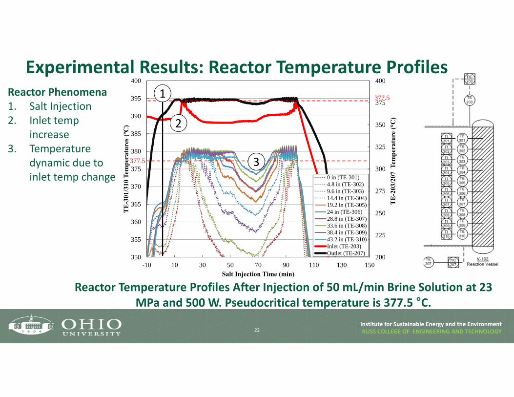
200
225
250
275
300
325
350
375
400
350
355
360
365
370
375
380
385
390
395
400
-10 10 30 50 70 90 110 130 150
TE
-203
/207
Tem
pera
ture
(°C
)
TE
-301
/310
Tem
pera
ture
s (º
C)
Salt Injection Time (min)
0 in (TE-301)4.8 in (TE-302)9.6 in (TE-303)14.4 in (TE-304)19.2 in (TE-305)24 in (TE-306)28.8 in (TE-307)33.6 in (TE-308)38.4 in (TE-309)43.2 in (TE-310)Inlet (TE-203)Outlet (TE-207)
377.5
377.5
Institute for Sustainable Energy and the Environment
Experimental Results: Reactor Temperature Profiles
22
Reactor Temperature Profiles After Injection of 50 mL/min Brine Solution at 23 MPa and 500 W. Pseudocritical temperature is 377.5 °C.
1
2
3
Reactor Phenomena1. Salt Injection2. Inlet temp
increase3. Temperature
dynamic due to inlet temp change

RUSS COLLEGE OF ENGINEERING AND TECHNOLOGYInstitute for Sustainable Energy and the Environment
Experimental Results (Cont.)
23
0
10
20
30
40
50
60
70
0 50 100 150 200 250 300
Eff
luen
t Ca2+
Con
cent
rtio
n (m
g/l)
ρH2O (kg/m3)
Internally Heated Reactor Operating Range
Experimentally determined effluent a) Na+ and b) Ca2+ concentrations based upon water density
a) b)

RUSS COLLEGE OF ENGINEERING AND TECHNOLOGYInstitute for Sustainable Energy and the Environment
Experimental Results (Cont.)
24
Experimentally determined effluent a) Mg2+ and b) Cl- concentrations based upon water density
a) b)

RUSS COLLEGE OF ENGINEERING AND TECHNOLOGYInstitute for Sustainable Energy and the Environment
Summary
25
Preliminary Conclusions1. Internally heated reactor design is capable of
heating brine solution to critical condition.2. Minimal heating occurs beyond the critical point
due to precipitation of dissolved solids and resulting decrease in solution conductivity.
3. Water density is major factor controlling TDS removal level.
4. TDS removal greater than 99.5% from solutions containing greater than 100k ppm TDS.
5. Internally heated reactor design shows capability of producing water product with multiple beneficial reuse applications.
Power Plant Makeup Water Quality Guidelines and Preliminary OHIO Water Product Results
Constituent FGD Circulation Water
Boiler Feedwater
PreliminaryProduct Quality
pH 6.0-9.0 6.8-7.21 9.3-9.6 6.2SO4
2- (mg/L) 300 147,200 0 BDLCl- (mg/L) 100-110 - 0 200-850Fl- (mg/L) 2 - 0 DNT
Fetotal (mg/L) 2 <0.5 <.01 DNTCa2+ (mg/L) 100-150 900 0 7-38Mg2+ (mg/L) 30-50 - 0 1-3.8Na+ (mg/L) 75-125 - 0.003-0.005 180-700
HCO3- (mg/L) 150-200 30-2501 0 BDL
Mn2+ (mg/L) - <0.5 0 DNTAl3+ (mg/L) - <1 0 DNTCu2+ (mg/L) - <0.1 <0.002 DNTNH3
- (mg/L) - <2 <0.02 DNTSiO2 (mg/L) 10-50 150 0 DNT
Mg x SiO2 - 35,000-75,000 0 DNT
TSS (mg/L) 200-300 100-300 0 0
Turbidity (NTU) 200-2,000 - 0 DNT
Conductivity (µS/cm)
500-1,000 - 0.5, Max. DNT
Hardness (mgCaCO3/L) 200-300 500,000 0 DNT
Oil & Grease 0 0 0 0
BDL: Below detectable limitDNT: Did not test to date

RUSS COLLEGE OF ENGINEERING AND TECHNOLOGYInstitute for Sustainable Energy and the Environment
Upcoming Work
26
OHIO• Continue prototype testing to evaluate TDS removal efficiency and evaluate reactor
operability (Ongoing)• Update existing techno-economic analyses using newly generated experimental data
(Starting mid-May)
WVU• Continue evaluating electrocoagulation and electrochemical stripping techniques to
remove high-value trace elements (Ongoing)• Begin evaluating corrosion resistant cladding materials for low-cost steels (Starting June)