Embed Size (px)
Citation preview
AIDA-2020-SLIDE-2018-039
AIDA-2020Advanced European Infrastructures for Detectors at Accelerators
Presentation
The Semi-Digital Hadronic Calorimeter(SDHCAL) prototype
Fouz Iglesias, M. (CIEMAT)
03 October 2017
The AIDA-2020 Advanced European Infrastructures for Detectors at Accelerators projecthas received funding from the European Union’s Horizon 2020 Research and Innovation
programme under Grant Agreement no. 654168.
This work is part of AIDA-2020 Work Package 14: Infrastructure for advancedcalorimeters.
The electronic version of this AIDA-2020 Publication is available via the AIDA-2020 web site<http://aida2020.web.cern.ch> or on the CERN Document Server at the following URL:
<http://cds.cern.ch/search?p=AIDA-2020-SLIDE-2018-039>
Copyright c© CERN for the benefit of the AIDA-2020 Consortium
The Semi-Digital Hadronic Calorimeter(SDHCAL) prototype
M.C Fouz (CIEMAT) (On behalf of CALICE Collaboration)
SDHCAL – Main characteristics
M.C Fouz CHEF, Lyon 2-6 Oct 2017 2
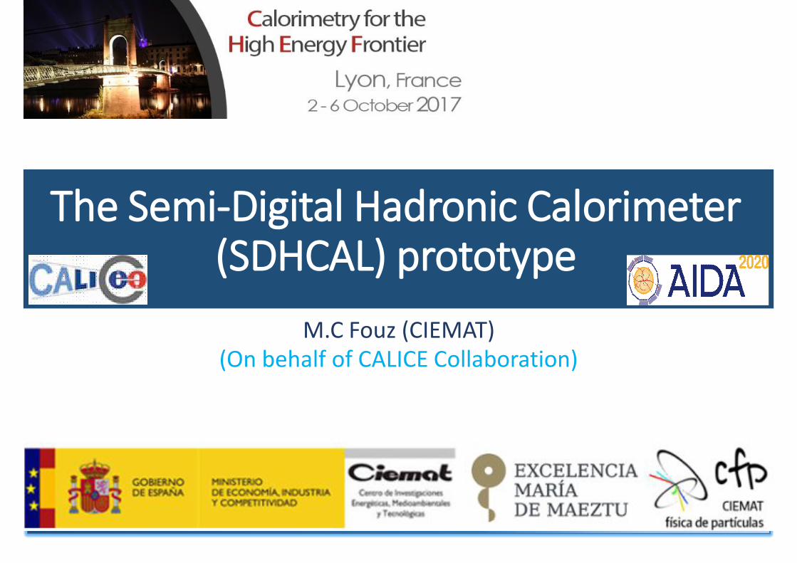
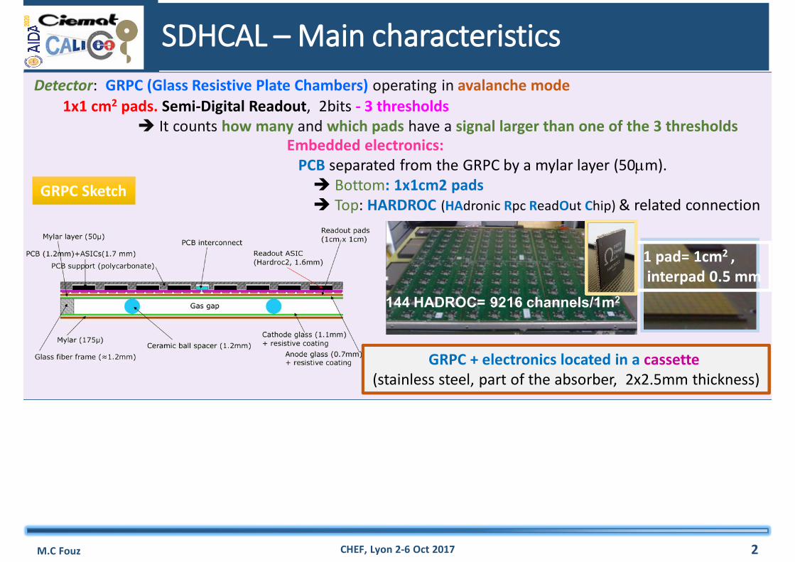
1x1 cm2 pads. Semi-Digital Readout, 2bits - 3 thresholds It counts how many and which pads have a signal larger than one of the 3 thresholds
Detector: GRPC (Glass Resistive Plate Chambers) operating in avalanche mode
GRPC Sketch
SDHCAL – Main characteristics
M.C Fouz CHEF, Lyon 2-6 Oct 2017 2
1x1 cm2 pads. Semi-Digital Readout, 2bits - 3 thresholds It counts how many and which pads have a signal larger than one of the 3 thresholds
Detector: GRPC (Glass Resistive Plate Chambers) operating in avalanche mode
GRPC Sketch
Embedded electronics: PCB separated from the GRPC by a mylar layer (50m). Bottom: 1x1cm2 pads Top: HARDROC (HAdronic Rpc ReadOut Chip) & related connection
144 HADROC= 9216 channels/1m2
1 pad= 1cm2 ,interpad 0.5 mm
GRPC + electronics located in a cassette(stainless steel, part of the absorber, 2x2.5mm thickness)
SDHCAL – Main characteristics
M.C Fouz CHEF, Lyon 2-6 Oct 2017 2
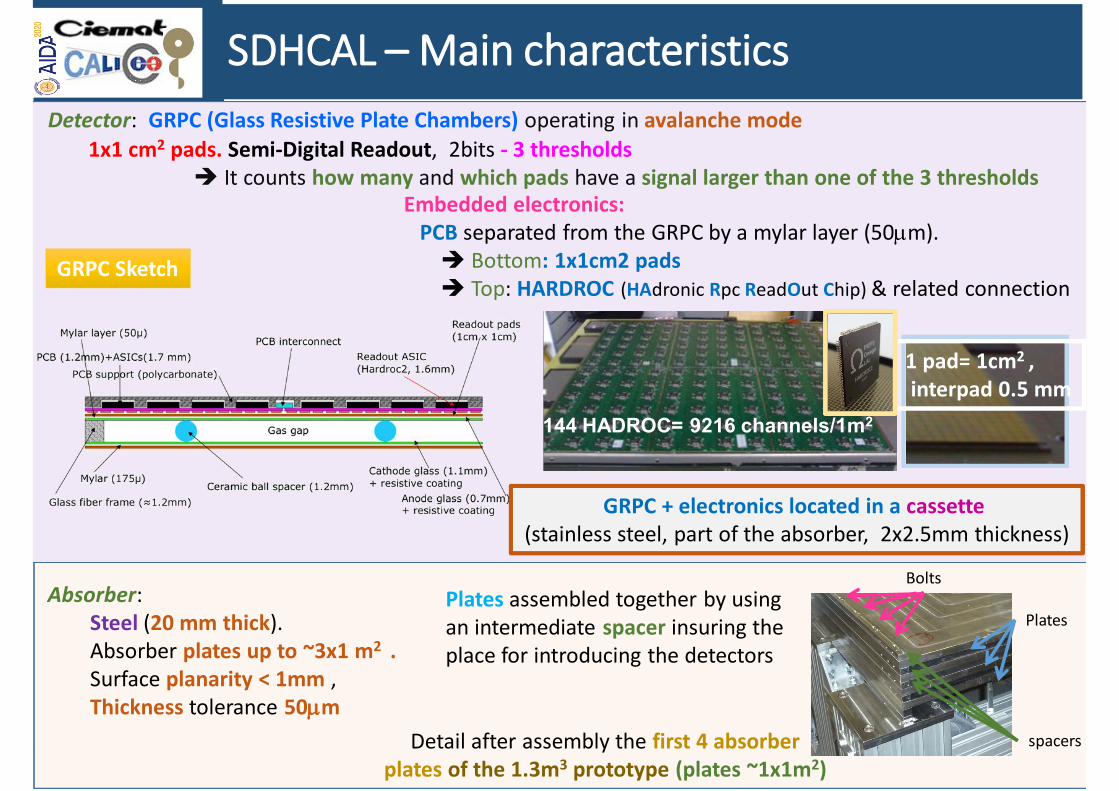
Absorber: Steel (20 mm thick). Absorber plates up to ~3x1 m2 . Surface planarity < 1mm , Thickness tolerance 50m
Plates
spacers
Plates assembled together by using an intermediate spacer insuring the place for introducing the detectors
Bolts
Detail after assembly the first 4 absorber plates of the 1.3m3 prototype (plates ~1x1m2)
1x1 cm2 pads. Semi-Digital Readout, 2bits - 3 thresholds It counts how many and which pads have a signal larger than one of the 3 thresholds
Detector: GRPC (Glass Resistive Plate Chambers) operating in avalanche mode
GRPC Sketch
Embedded electronics: PCB separated from the GRPC by a mylar layer (50m). Bottom: 1x1cm2 pads Top: HARDROC (HAdronic Rpc ReadOut Chip) & related connection
144 HADROC= 9216 channels/1m2
1 pad= 1cm2 ,interpad 0.5 mm
GRPC + electronics located in a cassette(stainless steel, part of the absorber, 2x2.5mm thickness)
~1.3 m3 SDHCAL prototype
M.C Fouz CHEF, Lyon 2-6 Oct 2017
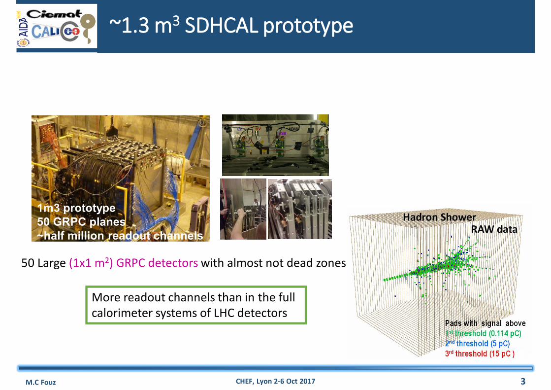
1m3 prototype50 GRPC planes~half million readout channels
50 Large (1x1 m2) GRPC detectors with almost not dead zones
3
More readout channels than in the full calorimeter systems of LHC detectors
SDHCAL Prototype Performance
M.C Fouz CHEF, Lyon 2-6 Oct 2017 4
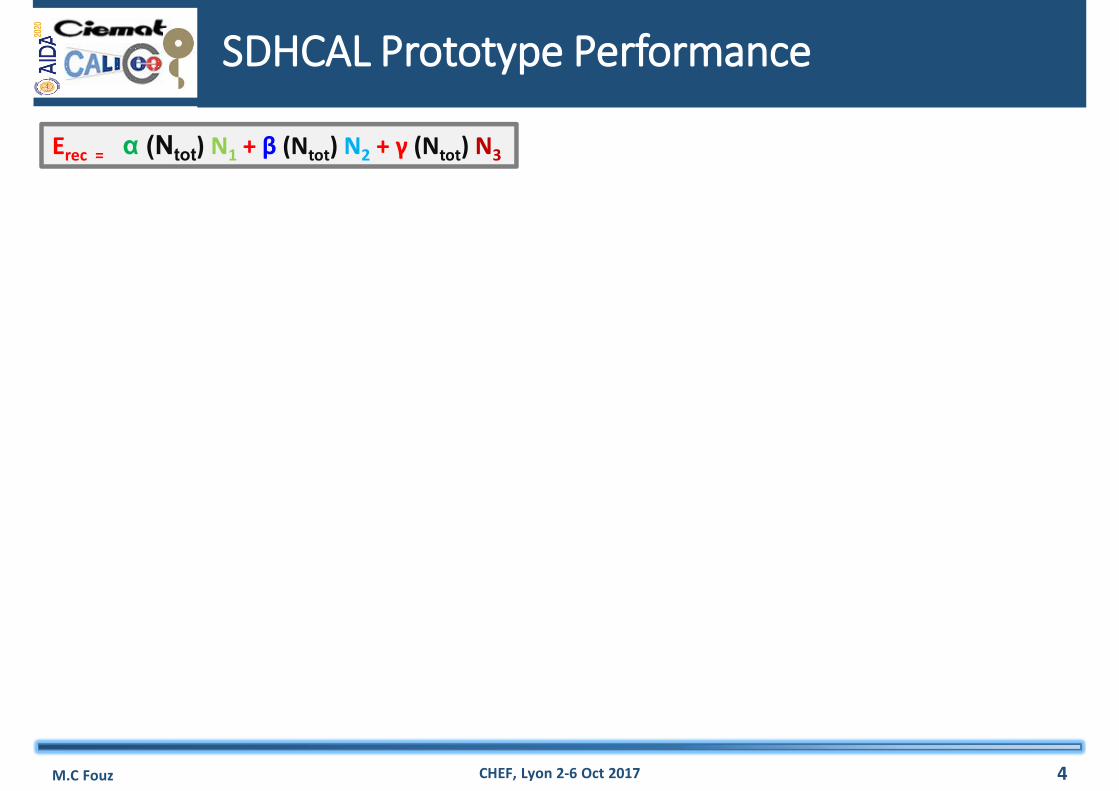
Erec = α (Ntot) N1 + β (Ntot) N2 + γ (Ntot) N3

SDHCAL Prototype Performance
M.C Fouz CHEF, Lyon 2-6 Oct 2017 4
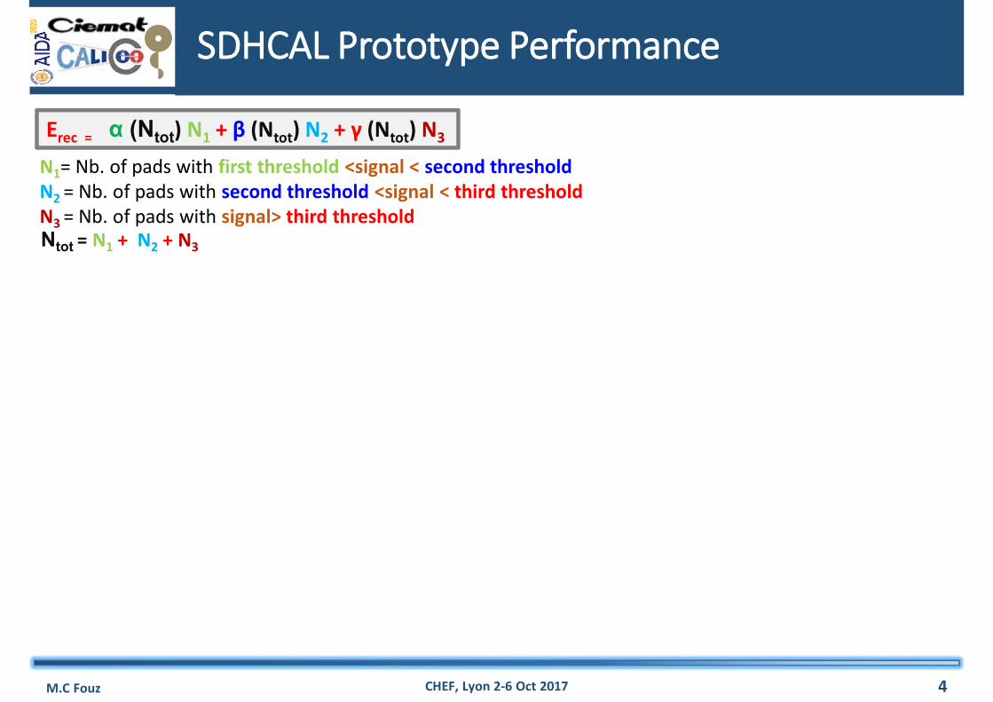
N1= Nb. of pads with first threshold <signal < second thresholdN2 = Nb. of pads with second threshold <signal < third thresholdN3 = Nb. of pads with signal> third threshold
Erec = α (Ntot) N1 + β (Ntot) N2 + γ (Ntot) N3
SDHCAL Prototype Performance
M.C Fouz CHEF, Lyon 2-6 Oct 2017 4
N1= Nb. of pads with first threshold <signal < second thresholdN2 = Nb. of pads with second threshold <signal < third thresholdN3 = Nb. of pads with signal> third threshold
Erec = α (Ntot) N1 + β (Ntot) N2 + γ (Ntot) N3
Ntot = N1 + N2 + N3
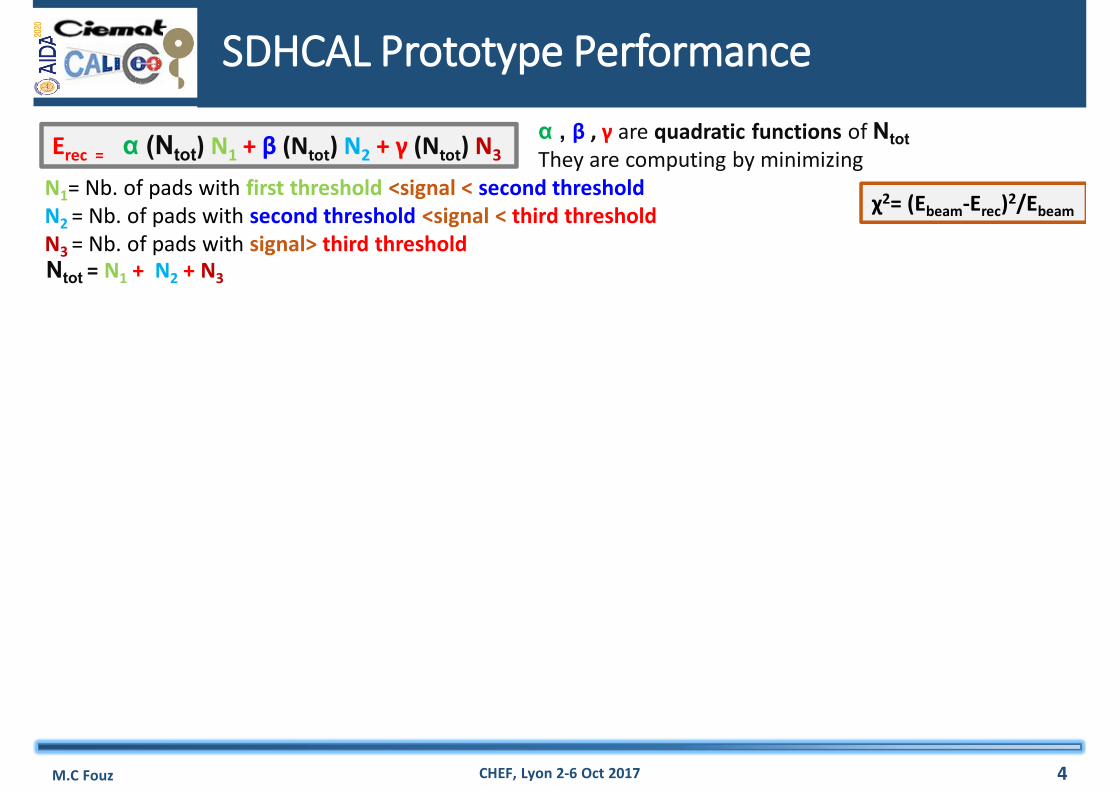
α , β , γ are quadratic functions of NtotThey are computing by minimizing
χ2= (Ebeam-Erec)2/Ebeam
SDHCAL Prototype Performance
M.C Fouz CHEF, Lyon 2-6 Oct 2017 4
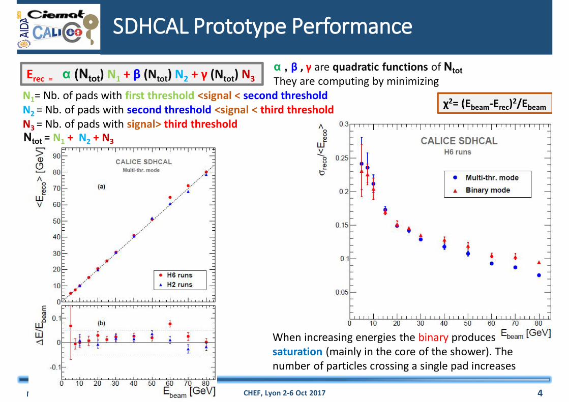
N1= Nb. of pads with first threshold <signal < second thresholdN2 = Nb. of pads with second threshold <signal < third thresholdN3 = Nb. of pads with signal> third threshold
Erec = α (Ntot) N1 + β (Ntot) N2 + γ (Ntot) N3
Ntot = N1 + N2 + N3
α , β , γ are quadratic functions of NtotThey are computing by minimizing
χ2= (Ebeam-Erec)2/Ebeam
When increasing energies the binary produces saturation (mainly in the core of the shower). The number of particles crossing a single pad increases
SDHCAL – Single Track reconstruction
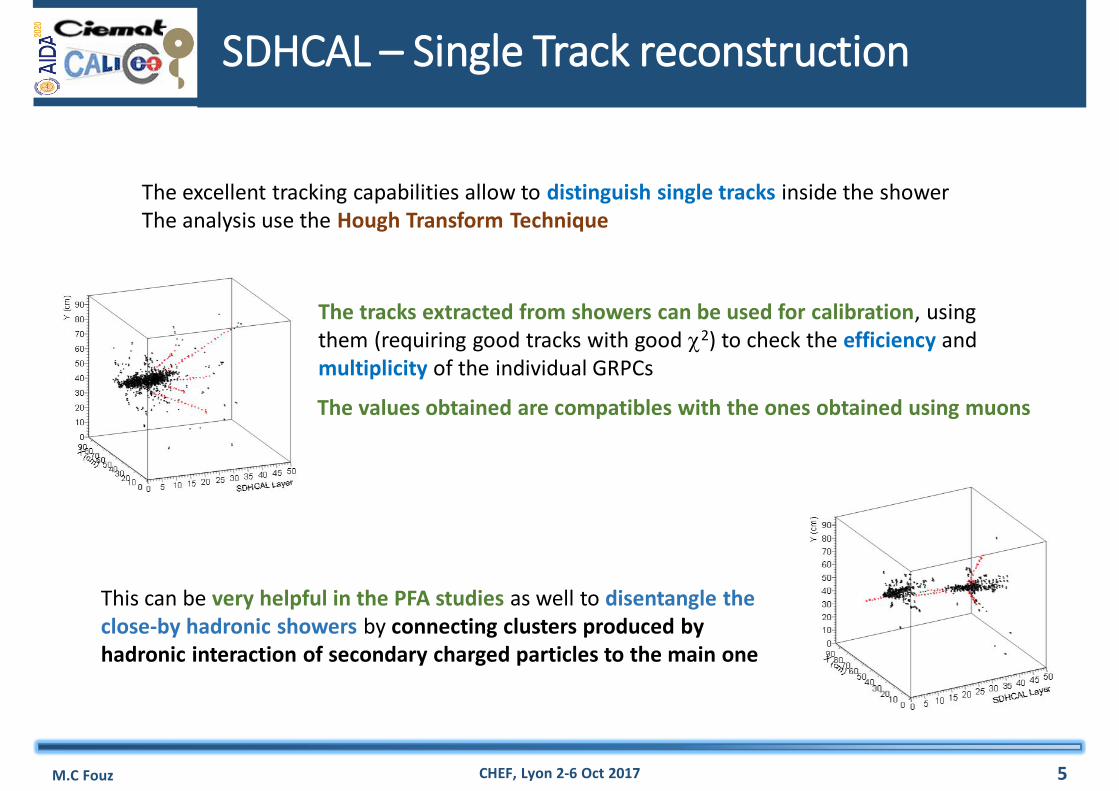
The excellent tracking capabilities allow to distinguish single tracks inside the showerThe analysis use the Hough Transform Technique
The tracks extracted from showers can be used for calibration, using them (requiring good tracks with good 2) to check the efficiency and multiplicity of the individual GRPCs
The values obtained are compatibles with the ones obtained using muons
This can be very helpful in the PFA studies as well to disentangle the close-by hadronic showers by connecting clusters produced by hadronic interaction of secondary charged particles to the main one
M.C Fouz CHEF, Lyon 2-6 Oct 2017 5
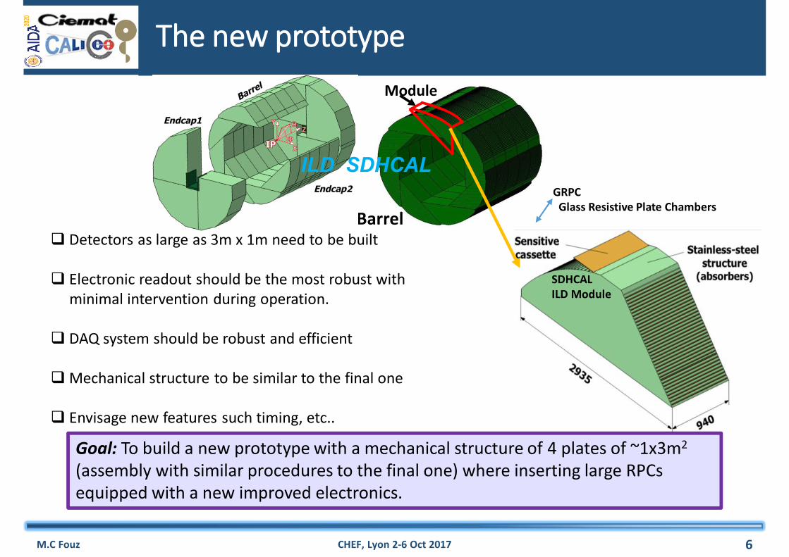
Barrel
Module
SDHCALILD Module
GRPCGlass Resistive Plate Chambers
The new prototype
M.C Fouz CHEF, Lyon 2-6 Oct 2017 6
Goal: To build a new prototype with a mechanical structure of 4 plates of ~1x3m2
(assembly with similar procedures to the final one) where inserting large RPCs equipped with a new improved electronics.
Detectors as large as 3m x 1m need to be built
Electronic readout should be the most robust withminimal intervention during operation.
DAQ system should be robust and efficient
Mechanical structure to be similar to the final one
Envisage new features such timing, etc..
ILD SDHCAL
New electronics: ASIC,PCB,DIF
M.C Fouz CHEF, Lyon 2-6 Oct 2017 7
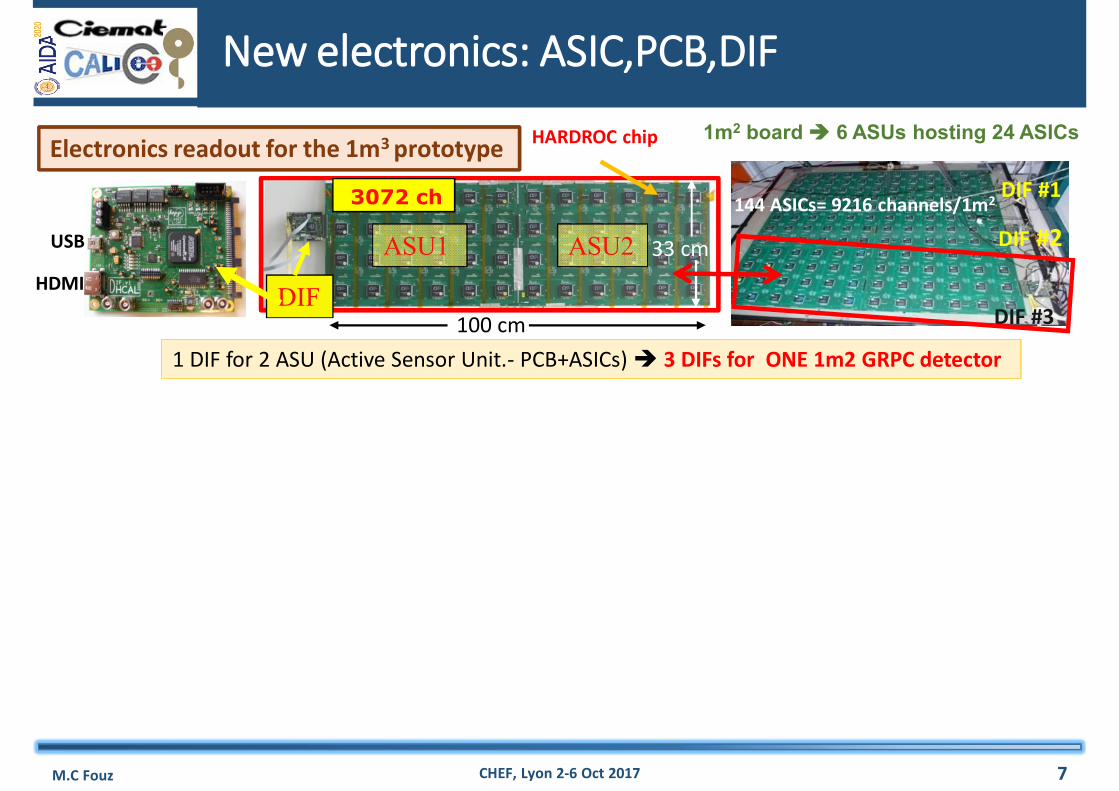
DIF #1
DIF #2
DIF #3
144 ASICs= 9216 channels/1m2
USB
HDMI
ASU1
3072 ch
ASU2
DIF100 cm
33 cm
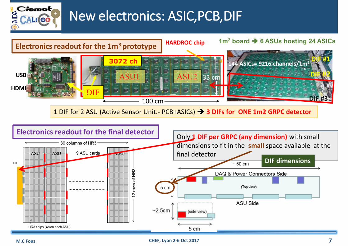
HARDROC chip 1m2 board 6 ASUs hosting 24 ASICs Electronics readout for the 1m3 prototype
1 DIF for 2 ASU (Active Sensor Unit.- PCB+ASICs) 3 DIFs for ONE 1m2 GRPC detector
New electronics: ASIC,PCB,DIF
M.C Fouz CHEF, Lyon 2-6 Oct 2017 7
DIF #1
DIF #2
DIF #3
144 ASICs= 9216 channels/1m2
USB
HDMI
ASU1
3072 ch
ASU2
DIF100 cm
33 cm
HARDROC chip 1m2 board 6 ASUs hosting 24 ASICs Electronics readout for the 1m3 prototype
1 DIF for 2 ASU (Active Sensor Unit.- PCB+ASICs) 3 DIFs for ONE 1m2 GRPC detector
Electronics readout for the final detectorOnly 1 DIF per GRPC (any dimension) with small dimensions to fit in the small space available at the final detector
DIF dimensions
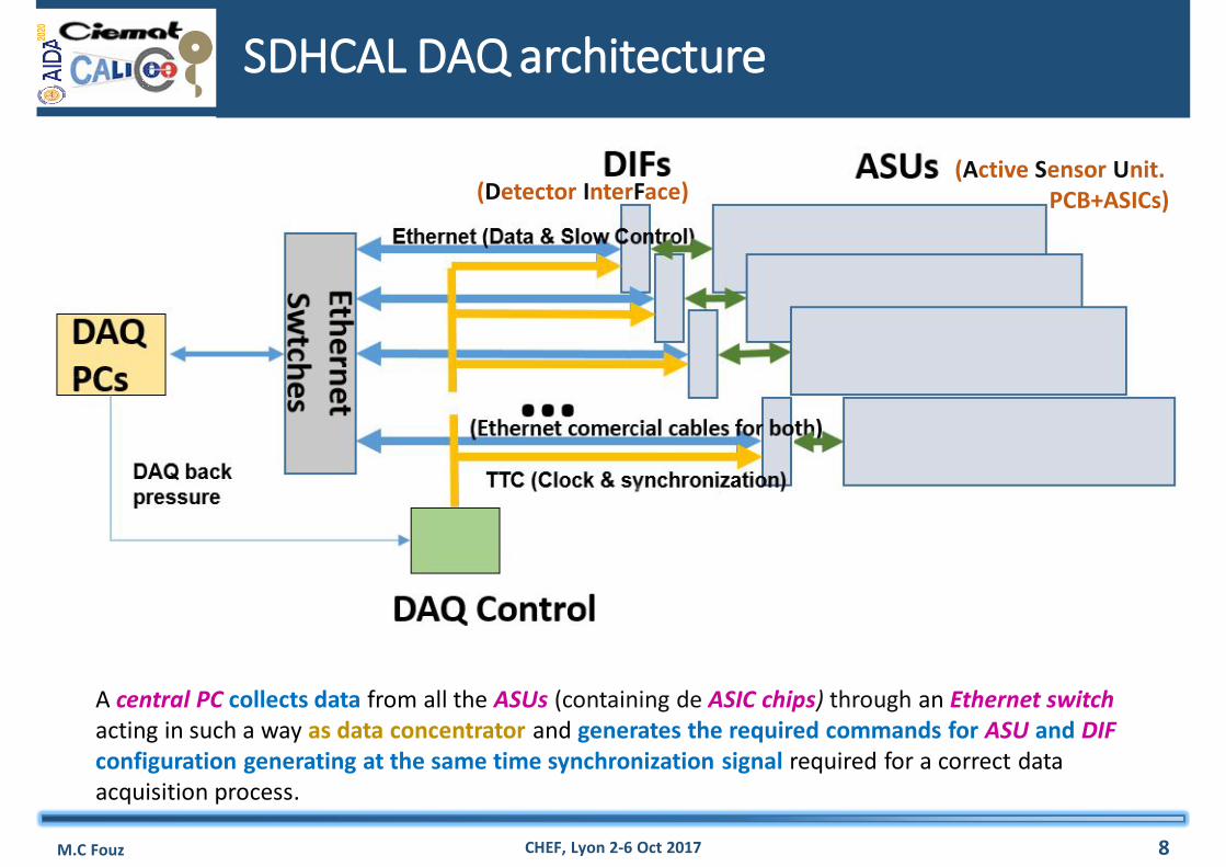
SDHCAL DAQ architecture
M.C Fouz CHEF, Lyon 2-6 Oct 2017 8
A central PC collects data from all the ASUs (containing de ASIC chips) through an Ethernet switch acting in such a way as data concentrator and generates the required commands for ASU and DIF configuration generating at the same time synchronization signal required for a correct data acquisition process.
(Active Sensor Unit.PCB+ASICs)(Detector InterFace)
ASIC – HARDROC3
M.C Fouz CHEF, Lyon 2-6 Oct 2017 9
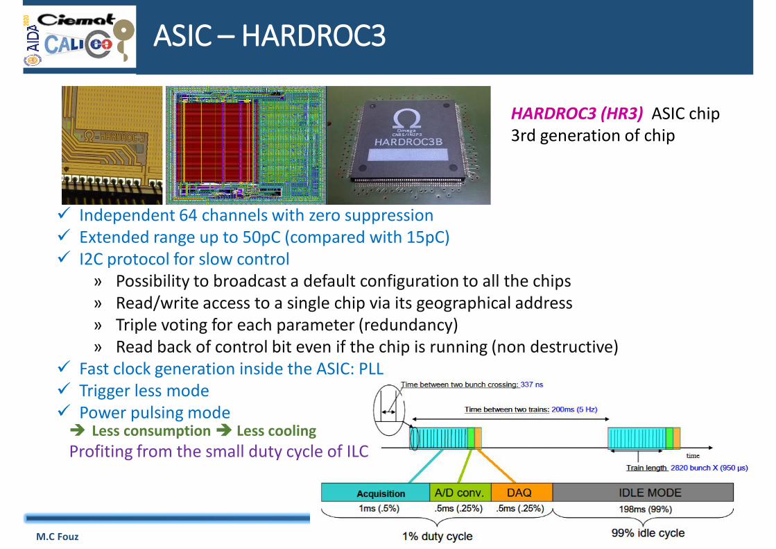
HARDROC3 (HR3) ASIC chip3rd generation of chip
Independent 64 channels with zero suppression Extended range up to 50pC (compared with 15pC) I2C protocol for slow control
» Possibility to broadcast a default configuration to all the chips» Read/write access to a single chip via its geographical address» Triple voting for each parameter (redundancy) » Read back of control bit even if the chip is running (non destructive)
Fast clock generation inside the ASIC: PLL Trigger less mode Power pulsing mode Less consumption Less coolingProfiting from the small duty cycle of ILC
ASIC – HARDROC3 (II)
M.C Fouz CHEF, Lyon 2-6 Oct 2017 10
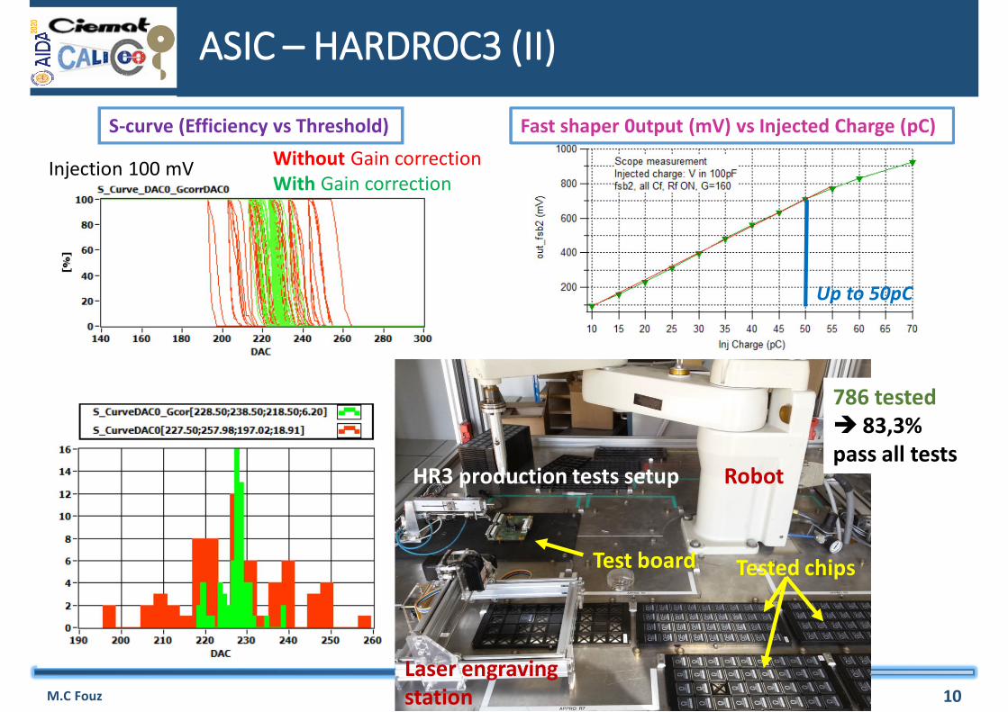
S-curve (Efficiency vs Threshold)
Injection 100 mV Without Gain correctionWith Gain correction
Fast shaper 0utput (mV) vs Injected Charge (pC)
Up to 50pC
HR3 production tests setup Robot
Test board Tested chips
Laser engraving station
786 tested 83,3% pass all tests
ASU (Active Sensor Unit)
M.C Fouz CHEF, Lyon 2-6 Oct 2017 11
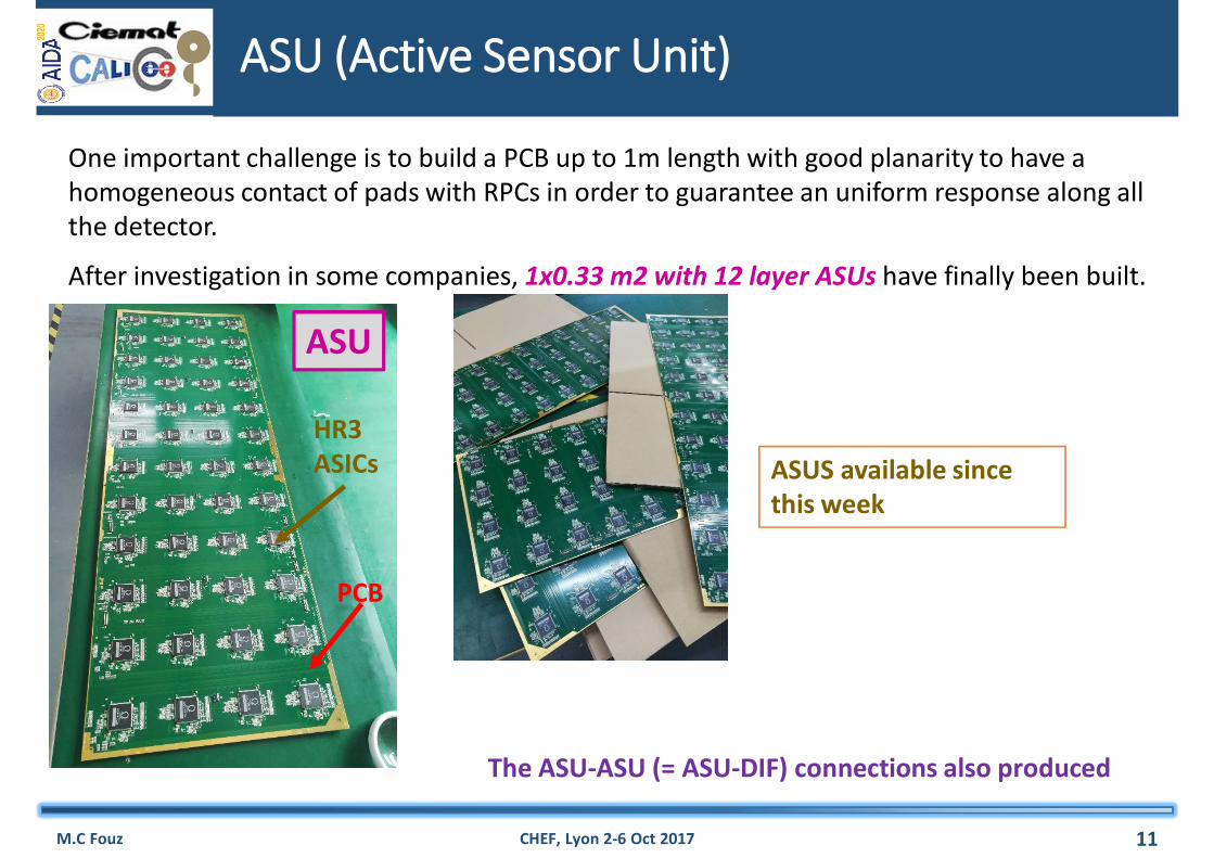
One important challenge is to build a PCB up to 1m length with good planarity to have a homogeneous contact of pads with RPCs in order to guarantee an uniform response along all the detector.
After investigation in some companies, 1x0.33 m2 with 12 layer ASUs have finally been built.
ASUS available since this week
ASU
PCB
HR3ASICs
The ASU-ASU (= ASU-DIF) connections also produced
DIF (Detector InterFace): architecture
M.C Fouz CHEF, Lyon 2-6 Oct 2017 12
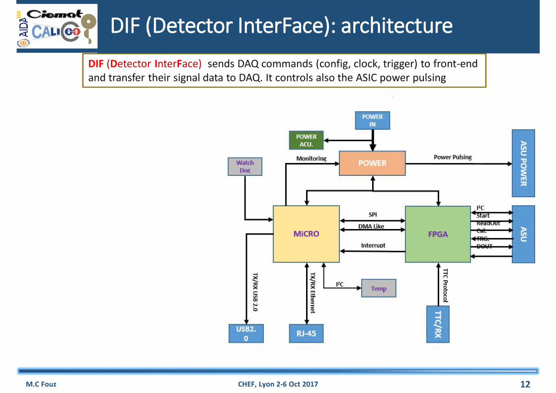
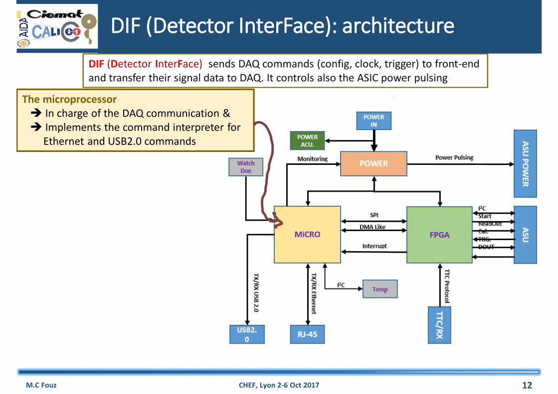
DIF (Detector InterFace) sends DAQ commands (config, clock, trigger) to front-end and transfer their signal data to DAQ. It controls also the ASIC power pulsing
DIF (Detector InterFace): architecture
M.C Fouz CHEF, Lyon 2-6 Oct 2017 12
The microprocessor In charge of the DAQ communication & Implements the command interpreter for
Ethernet and USB2.0 commands
A SPI (Serial Peripheral Interface) link allows to communicate the microprocessor with a FPGA
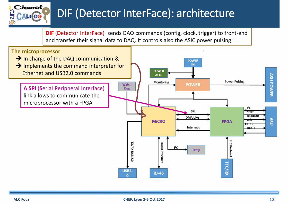
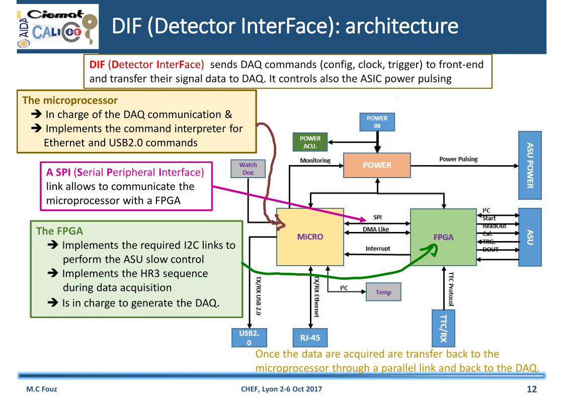
The FPGA Implements the required I2C links to
perform the ASU slow control Implements the HR3 sequence
during data acquisition Is in charge to generate the DAQ.
Once the data are acquired are transfer back to themicroprocessor through a parallel link and back to the DAQ.
DIF (Detector InterFace) sends DAQ commands (config, clock, trigger) to front-end and transfer their signal data to DAQ. It controls also the ASIC power pulsing

TTCX
I2C DriversI2C Drivers
Test signal
Trigger ext.ASU cnct.
DIF Design
September 2017
Still missed Super capacitor ASU DAQ connections
M.C Fouz CHEF, Lyon 2-6 Oct 2017 13
POWERPOWER
FPGA(Xilinx XC7A35TFGG484)
Microprocessor (TEXAS TM4C129U)
6 cm
70 cm
22/9/2017
• Only one DIF per plane (instead of three)• DIF handle up to 432 HR3 chips (vs 48 HR2 in previous DIF)• Clock and synchronization by TTC (already used in LHC)• 93W Peak power supply with super-capacitors (vs 8.6 W in previous DIF)• Spare I/O connectors to the FPGA (i.e. for GBT links)• Upgrade USB 1.1 to USB 2.0
Next step Tests with ASU
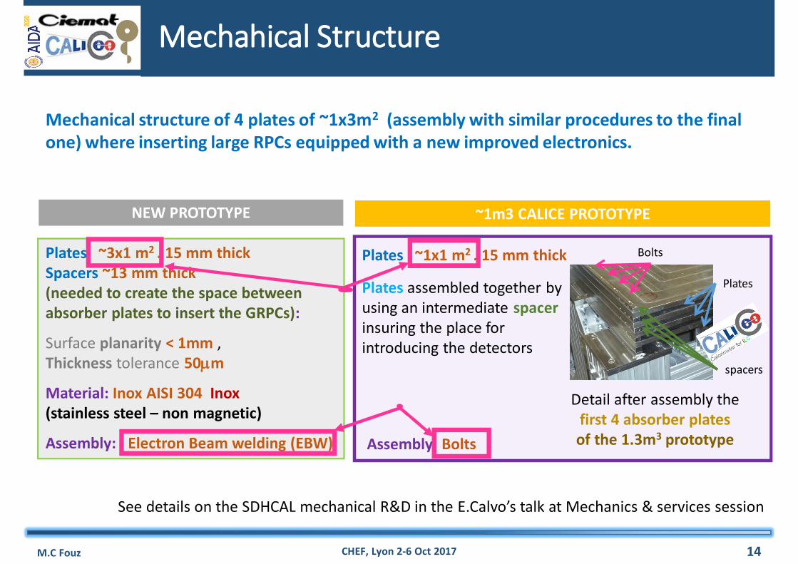
NEW PROTOTYPE
Plates ~3x1 m2 . 15 mm thickSpacers ~13 mm thick(needed to create the space between absorber plates to insert the GRPCs):
Surface planarity < 1mm , Thickness tolerance 50m
Material: Inox AISI 304 Inox(stainless steel – non magnetic)
Assembly: Electron Beam welding (EBW)
Plates
spacers
Plates ~1x1 m2 . 15 mm thick
Plates assembled together by using an intermediate spacerinsuring the place for introducing the detectors
Bolts
Detail after assembly the first 4 absorber plates of the 1.3m3 prototype
~1m3 CALICE PROTOTYPE
Assembly: Bolts
Mechanical structure of 4 plates of ~1x3m2 (assembly with similar procedures to the final one) where inserting large RPCs equipped with a new improved electronics.
Mechahical Structure
M.C Fouz CHEF, Lyon 2-6 Oct 2017 14
See details on the SDHCAL mechanical R&D in the E.Calvo’s talk at Mechanics & services session
Plates production & Quality Control
M.C Fouz CHEF, Lyon 2-6 Oct 2017
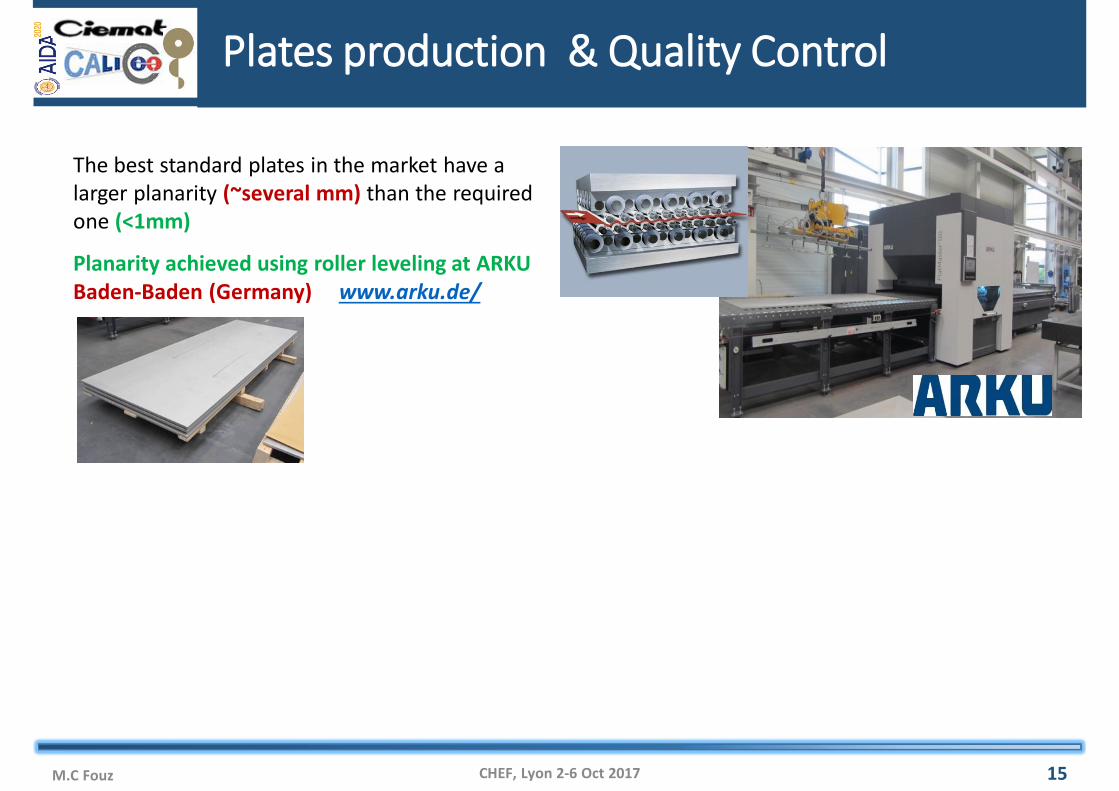
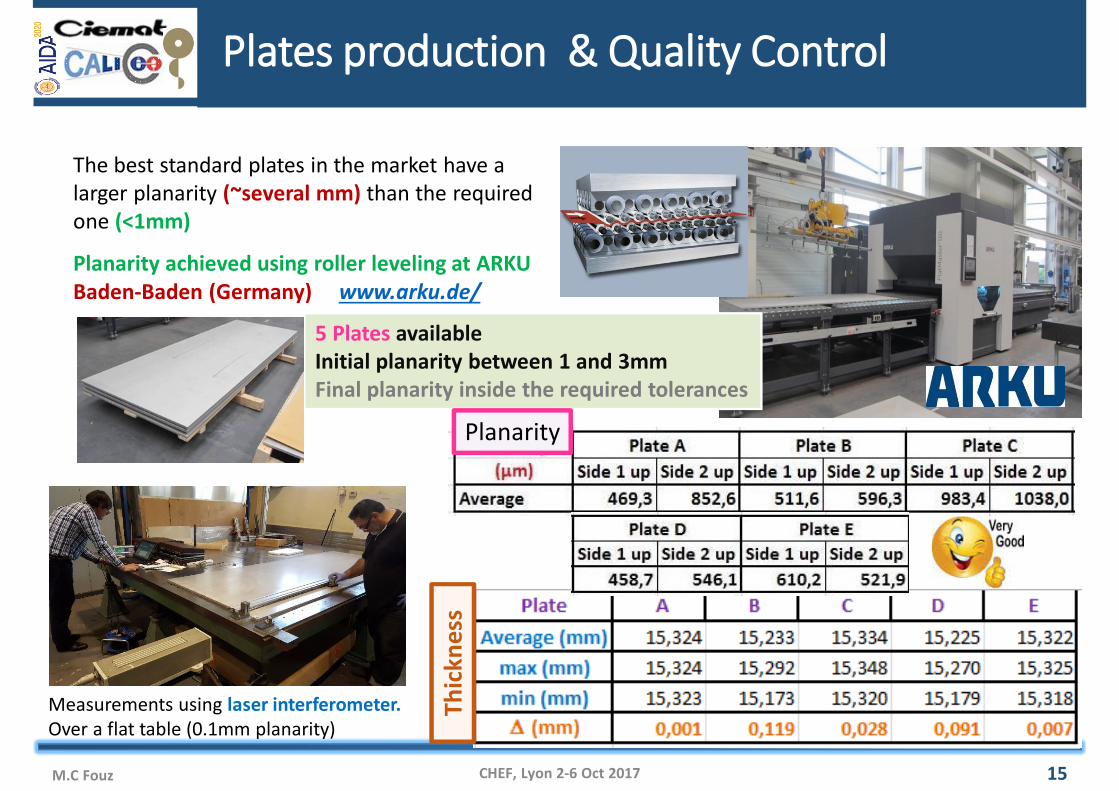
The best standard plates in the market have a larger planarity (~several mm) than the required one (<1mm)
Planarity achieved using roller leveling at ARKU Baden-Baden (Germany) www.arku.de/
15
Plates production & Quality Control
M.C Fouz CHEF, Lyon 2-6 Oct 2017
The best standard plates in the market have a larger planarity (~several mm) than the required one (<1mm)
Planarity achieved using roller leveling at ARKU Baden-Baden (Germany) www.arku.de/
5 Plates available Initial planarity between 1 and 3mmFinal planarity inside the required tolerances
Measurements using laser interferometer. Over a flat table (0.1mm planarity)
Thic
knes
s
15
Planarity
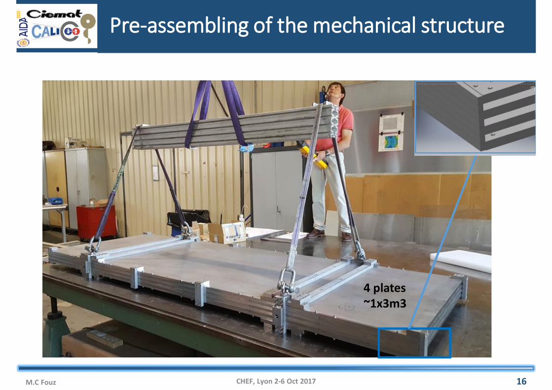
Pre-assembling of the mechanical structure
M.C Fouz CHEF, Lyon 2-6 Oct 2017 16
4 plates~1x3m3
Summary
CHEF, Lyon 2-6 Oct 2017 16M.C Fouz
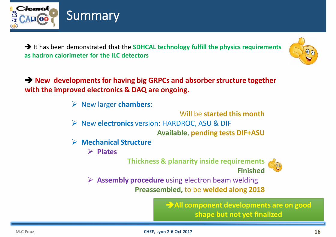
It has been demonstrated that the SDHCAL technology fulfill the physics requirements as hadron calorimeter for the ILC detectors
New developments for having big GRPCs and absorber structure together with the improved electronics & DAQ are ongoing.
New larger chambers: Will be started this month
New electronics version: HARDROC, ASU & DIF Available, pending tests DIF+ASU
Mechanical Structure Plates
Thickness & planarity inside requirements Finished
Assembly procedure using electron beam weldingPreassembled, to be welded along 2018
All component developments are on good shape but not yet finalized