Embed Size (px)
Citation preview
Advanced Diagnostic Functions of EJX Series Differential Pressure/Pressure Transmitters
Yokogawa Technical Report English Edition Vol.53 No.2 (2010)
Advanced Diagnostic Functions of EJX Series Differential Pressure/Pressure TransmittersKiyoshi Watanabe *1
Diagnosing the process interface where the field instruments and process equipment are contacting each other enables prediction of the required maintenance for the instrumentation. With the EJX series differential pressure/pressure transmitters, Yokogawa has developed functions to detect blockage and monitor heat traces in impulse lines which are process interface parts. These functions are called advanced diagnoses, to distinguish them from the self-diagnosis of the instruments. This paper introduces the advanced diagnostic functions built in the FOUNDATION Fieldbus communication type and HART communication type EJX series transmitters.
INTRODUCTION
Field instruments are expected to be equipped with diagnost ic funct ions to predict abnormal process
conditions, and are also expected to expand these functions. The ability to extract diagnostic information for prediction and prevention from various physical process quantities measured by devices and make it available allows the user to reduce non-essential and non-urgent maintenance and thus cut maintenance costs. There are high expectations for field instruments to improve diagnostic functions to facilitate the management of devices and plant operations and help cut maintenance costs (1).
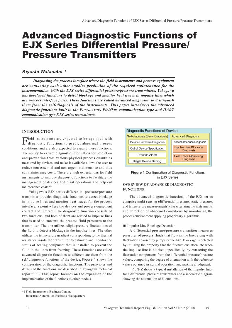
Yokogawa’s EJX series differential pressure/pressure transmitter provides diagnostic functions to detect blockage in impulse lines and monitor heat traces for the process interface, a point where the devices and process equipment contact and interact. The diagnostic function consists of two functions, and both of them are related to impulse lines that is used to transmit the process f luid pressures to the transmitter. The one utilizes slight pressure f luctuations of the fluid to detect a blockage in the impulse lines. The other utilizes the temperature gradient corresponding to the thermal resistance inside the transmitter to estimate and monitor the status of heating equipment that is installed to prevent the f luid in the lines from freezing. These functions are called advanced diagnostic functions to differentiate them from the self-diagnostic functions of the device. Figure 1 shows the configuration of the diagnostic functions. The principles and details of the functions are described in Yokogawa technical report (2), (3). This report focuses on the expansion of the implementation of the functions to other models.
Figure 1 Configuration of Diagnostic Functions in EJX Series
OVERVIEW OF ADVANCED DIAGNOSTIC FUNCTIONS
The advanced diagnostic functions of the EJX series comprise multi-sensing (differential pressure, static pressure, and temperature measurements) characterizing the instruments and detection of abnormal conditions by monitoring the process environment applying proprietary algorithms.
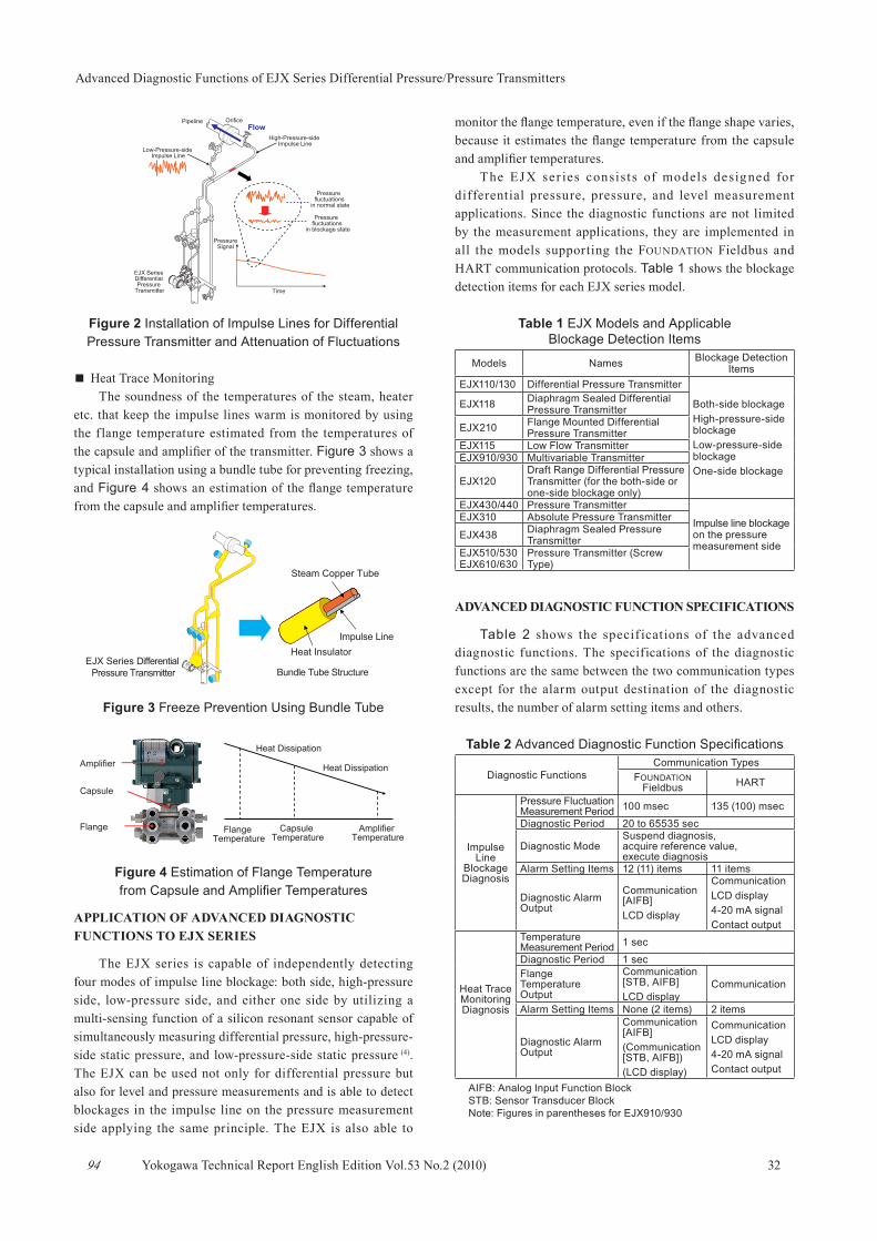
� Impulse Line Blockage DetectionA differential pressure/pressure transmitter measures
pressures of process fluids that f low in the line, along with fluctuations caused by pumps or the like. Blockage is detected by utilizing the property that the fluctuations attenuate when the impulse line is blocked; specifically, by extracting the fluctuation components from the differential pressure/pressure values, comparing the degree of attenuation with the reference values obtained in normal operation, and making a judgment.
Figure 2 shows a typical installation of the impulse lines for a differential pressure transmitter and a schematic diagram showing the attenuation of fluctuations.
Diagnostic Functions of DeviceSelf-diagnosis (Basic Diagnosis)
Device Hardware Diagnosis
Out of Device Specification
Process Alarm
Illegal Device Setting
Advanced Diagnosis
Process Interface Diagnosis
Impulse Line Blockage Diagnosis
Heat Trace Monitoring Diagnosis
*1 Field Instruments Business Center, Industrial Automation Business Headquarters
31 93
Advanced Diagnostic Functions of EJX Series Differential Pressure/Pressure Transmitters
Yokogawa Technical Report English Edition Vol.53 No.2 (2010)
Figure 2 Installation of Impulse Lines for Differential Pressure Transmitter and Attenuation of Fluctuations
� Heat Trace MonitoringThe soundness of the temperatures of the steam, heater
etc. that keep the impulse lines warm is monitored by using the f lange temperature estimated from the temperatures of the capsule and amplifier of the transmitter. Figure 3 shows a typical installation using a bundle tube for preventing freezing, and Figure 4 shows an estimation of the flange temperature from the capsule and amplifier temperatures.
Figure 3 Freeze Prevention Using Bundle Tube
Figure 4 Estimation of Flange Temperature from Capsule and Amplifier Temperatures
APPLICATION OF ADVANCED DIAGNOSTIC FUNCTIONS TO EJX SERIES
The EJX series is capable of independently detecting four modes of impulse line blockage: both side, high-pressure side, low-pressure side, and either one side by utilizing a multi-sensing function of a silicon resonant sensor capable of simultaneously measuring differential pressure, high-pressure-side static pressure, and low-pressure-side static pressure (4). The EJX can be used not only for differential pressure but also for level and pressure measurements and is able to detect blockages in the impulse line on the pressure measurement side applying the same principle. The EJX is also able to
monitor the flange temperature, even if the flange shape varies, because it estimates the flange temperature from the capsule and amplifier temperatures.
The EJX ser ies consists of models designed for differential pressure, pressure, and level measurement applications. Since the diagnostic functions are not limited by the measurement applications, they are implemented in all the models supporting the FOUNDATION Fieldbus and HART communication protocols. Table 1 shows the blockage detection items for each EJX series model.
ADVANCED DIAGNOSTIC FUNCTION SPECIFICATIONS
Table 2 shows the specif ications of the advanced diagnostic functions. The specifications of the diagnostic functions are the same between the two communication types except for the alarm output destination of the diagnostic results, the number of alarm setting items and others.
PipelineFlow
Pressure fluctuations
in blockage state
Pressure fluctuations
in normal state
High-Pressure-side Impulse Line
EJX Series Differential Pressure
Transmitter
Orifice
Low-Pressure-side Impulse Line
Time
PressureSignal
Impulse LineHeat Insulator
Steam Copper Tube
Bundle Tube StructureEJX Series Differential Pressure Transmitter
Flange Temperature
Capsule Temperature
Amplifier Temperature
Heat Dissipation
Heat Dissipation
Capsule
Amplifier
Flange
Table 1 EJX Models and Applicable Blockage Detection Items
Models Names Blockage Detection Items
EJX110/130 Differential Pressure Transmitter
Both-side blockageHigh-pressure-sideblockageLow-pressure-sideblockageOne-side blockage
EJX118 Diaphragm Sealed Differential Pressure Transmitter
EJX210 Flange Mounted Differential Pressure Transmitter
EJX115 Low Flow TransmitterEJX910/930 Multivariable Transmitter
EJX120Draft Range Differential Pressure Transmitter (for the both-side or one-side blockage only)
EJX430/440 Pressure Transmitter
Impulse line blockage on the pressure measurement side
EJX310 Absolute Pressure Transmitter
EJX438 Diaphragm Sealed Pressure Transmitter
EJX510/530EJX610/630
Pressure Transmitter (Screw Type)
Table 2 Advanced Diagnostic Function Specifications
Diagnostic FunctionsCommunication Types
FOUNDATION Fieldbus HART
Impulse Line
Blockage Diagnosis
Pressure Fluctuation Measurement Period 100 msec 135 (100) msecDiagnostic Period 20 to 65535 sec
Diagnostic ModeSuspend diagnosis, acquire reference value, execute diagnosis
Alarm Setting Items 12 (11) items 11 items
Diagnostic Alarm Output
Communication [AIFB] LCD display
CommunicationLCD display4-20 mA signalContact output
Heat Trace Monitoring Diagnosis
Temperature Measurement Period 1 secDiagnostic Period 1 secFlange Temperature Output
Communication [STB, AIFB] LCD display
Communication
Alarm Setting Items None (2 items) 2 items
Diagnostic Alarm Output
Communication [AIFB] (Communication [STB, AIFB]) (LCD display)
CommunicationLCD display4-20 mA signalContact output
AIFB: Analog Input Function BlockSTB: Sensor Transducer BlockNote: Figures in parentheses for EJX910/930
3294
Advanced Diagnostic Functions of EJX Series Differential Pressure/Pressure Transmitters
Yokogawa Technical Report English Edition Vol.53 No.2 (2010)
ADVANCED DIAGNOSTIC PROCESSING
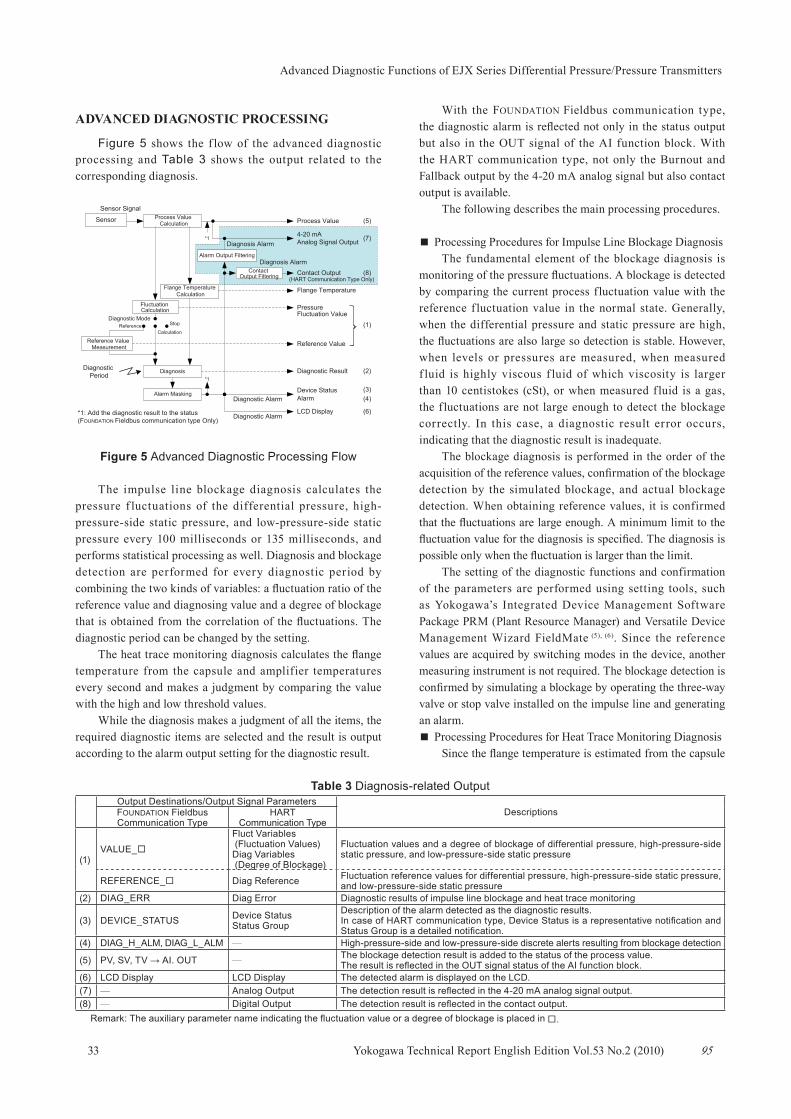
Figure 5 shows the f low of the advanced diagnostic processing and Table 3 shows the output related to the corresponding diagnosis.
Figure 5 Advanced Diagnostic Processing Flow
The impulse line blockage diagnosis calculates the pressure f luctuations of the differential pressure, high-pressure-side static pressure, and low-pressure-side static pressure every 100 milliseconds or 135 milliseconds, and performs statistical processing as well. Diagnosis and blockage detection are performed for every diagnostic period by combining the two kinds of variables: a fluctuation ratio of the reference value and diagnosing value and a degree of blockage that is obtained from the correlation of the fluctuations. The diagnostic period can be changed by the setting.
The heat trace monitoring diagnosis calculates the flange temperature from the capsule and amplifier temperatures every second and makes a judgment by comparing the value with the high and low threshold values.
While the diagnosis makes a judgment of all the items, the required diagnostic items are selected and the result is output according to the alarm output setting for the diagnostic result.
With the FOUNDATION Fieldbus communication type, the diagnostic alarm is reflected not only in the status output but also in the OUT signal of the AI function block. With the HART communication type, not only the Burnout and Fallback output by the 4-20 mA analog signal but also contact output is available.
The following describes the main processing procedures.
� Processing Procedures for Impulse Line Blockage Diagnosis The fundamental element of the blockage diagnosis is
monitoring of the pressure fluctuations. A blockage is detected by comparing the current process fluctuation value with the reference f luctuation value in the normal state. Generally, when the differential pressure and static pressure are high, the fluctuations are also large so detection is stable. However, when levels or pressures are measured, when measured f luid is highly viscous f luid of which viscosity is larger than 10 centistokes (cSt), or when measured f luid is a gas, the fluctuations are not large enough to detect the blockage correctly. In this case, a diagnostic result error occurs, indicating that the diagnostic result is inadequate.
The blockage diagnosis is performed in the order of the acquisition of the reference values, confirmation of the blockage detection by the simulated blockage, and actual blockage detection. When obtaining reference values, it is confirmed that the fluctuations are large enough. A minimum limit to the fluctuation value for the diagnosis is specified. The diagnosis is possible only when the fluctuation is larger than the limit.
The setting of the diagnostic functions and confirmation of the parameters are performed using setting tools, such as Yokogawa’s Integrated Device Management Software Package PRM (Plant Resource Manager) and Versatile Device Management Wizard FieldMate (5), (6). Since the reference values are acquired by switching modes in the device, another measuring instrument is not required. The blockage detection is confirmed by simulating a blockage by operating the three-way valve or stop valve installed on the impulse line and generating an alarm.
� Processing Procedures for Heat Trace Monitoring DiagnosisSince the flange temperature is estimated from the capsule
Sensor
Contact Output Filtering
Alarm Output Filtering
Process Value Calculation
Fluctuation Calculation
Flange Temperature Calculation
Reference Value Measurement
Diagnosis
Alarm Masking
Sensor Signal
4-20 mAAnalog Signal Output
Process Value
Device Status
LCD Display
Contact Output
Diagnostic ModeStopReference
Calculation
Reference Value
PressureFluctuation Value
Diagnostic Result
Diagnosis Alarm
Diagnosis Alarm
Diagnostic Alarm
Diagnostic Alarm
Flange Temperature
Diagnostic Period
(HART Communication Type Only)
*1
*1
(1)
(2)
(3)(4)
(5)
(6)
(7)
(8)
*1: Add the diagnostic result to the status(FOUNDATION Fieldbus communication type Only)
Alarm
33 95
Table 3 Diagnosis-related OutputOutput Destinations/Output Signal Parameters
DescriptionsFOUNDATION Fieldbus Communication Type
HART Communication Type
(1)VALUE_
Fluct Variables (Fluctuation Values) Diag Variables (Degree of Blockage)
Fluctuation values and a degree of blockage of differential pressure, high-pressure-side static pressure, and low-pressure-side static pressure
REFERENCE_ Diag Reference Fluctuation reference values for differential pressure, high-pressure-side static pressure, and low-pressure-side static pressure
(2) DIAG_ERR Diag Error Diagnostic results of impulse line blockage and heat trace monitoring
(3) DEVICE_STATUS Device StatusStatus Group
Description of the alarm detected as the diagnostic results.In case of HART communication type, Device Status is a representative notification and Status Group is a detailed notification.
(4) DIAG_H_ALM, DIAG_L_ALM — High-pressure-side and low-pressure-side discrete alerts resulting from blockage detection
(5) PV, SV, TV → AI. OUT — The blockage detection result is added to the status of the process value.The result is reflected in the OUT signal status of the AI function block.
(6) LCD Display LCD Display The detected alarm is displayed on the LCD.(7) — Analog Output The detection result is reflected in the 4-20 mA analog signal output.(8) — Digital Output The detection result is reflected in the contact output.
Remark: The auxiliary parameter name indicating the fluctuation value or a degree of blockage is placed in .
Advanced Diagnostic Functions of EJX Series Differential Pressure/Pressure Transmitters
Yokogawa Technical Report English Edition Vol.53 No.2 (2010)
and amplifier temperatures, a coefficient for calculating the flange temperature needs to be obtained. The coefficient is obtained by heating the flange and measuring its temperature before diagnosis, and then the obtained coefficient and the high and low temperature alarm threshold values are set for the device.
� Processing Procedures for Alarm MaskingFigure 6 shows the masking of diagnostic alarms for
the HART communication type. The diagnostic results of blockage detection and flange temperature error are kept in the Diag Error parameter and the output and display of the results are determined by the Diag Option parameter. With the FOUNDATION Fieldbus communication type, the diagnostic results are kept in the DIAG_ERR parameter, and the selection and output are subject to the DIAG_OPTION parameter.
Figure 6 Alarm Masking (for HART Communication Type)
GUI FOR ADVANCED DIAGNOSTIC
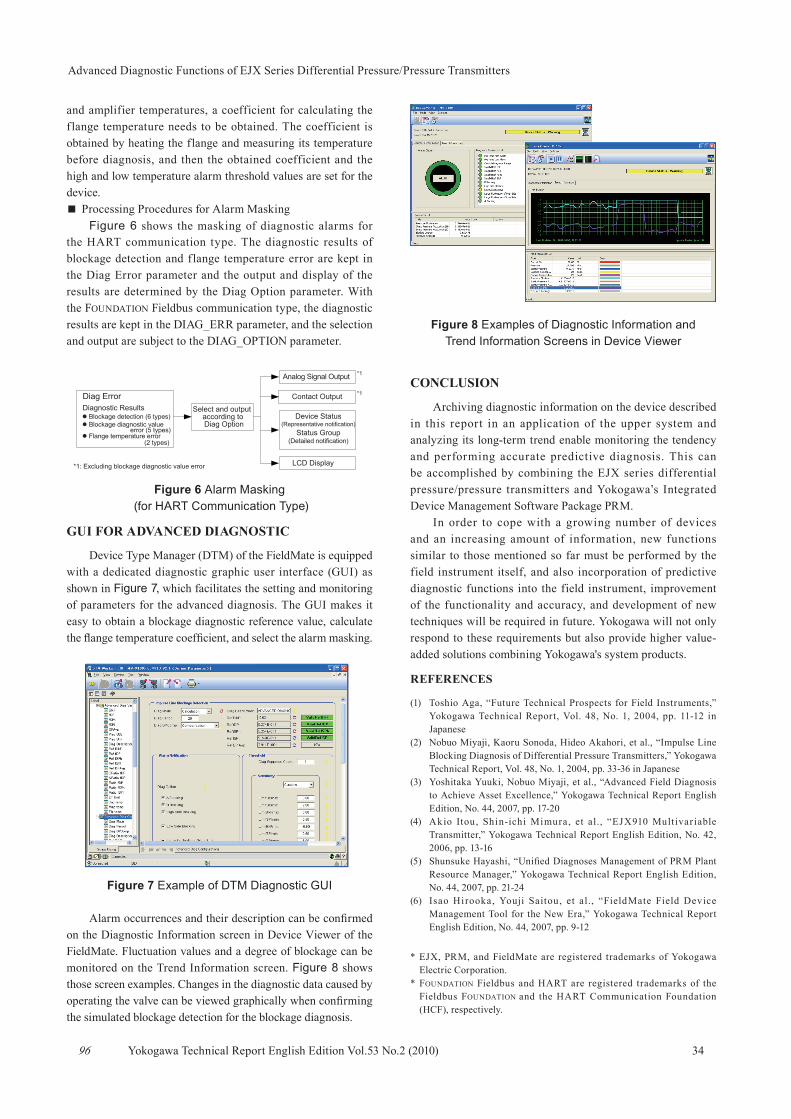
Device Type Manager (DTM) of the FieldMate is equipped with a dedicated diagnostic graphic user interface (GUI) as shown in Figure 7, which facilitates the setting and monitoring of parameters for the advanced diagnosis. The GUI makes it easy to obtain a blockage diagnostic reference value, calculate the flange temperature coefficient, and select the alarm masking.
Figure 7 Example of DTM Diagnostic GUI
Alarm occurrences and their description can be confirmed on the Diagnostic Information screen in Device Viewer of the FieldMate. Fluctuation values and a degree of blockage can be monitored on the Trend Information screen. Figure 8 shows those screen examples. Changes in the diagnostic data caused by operating the valve can be viewed graphically when confirming the simulated blockage detection for the blockage diagnosis.
Figure 8 Examples of Diagnostic Information and Trend Information Screens in Device Viewer
CONCLUSION
Archiving diagnostic information on the device described in this report in an application of the upper system and analyzing its long-term trend enable monitoring the tendency and performing accurate predictive diagnosis. This can be accomplished by combining the EJX series differential pressure/pressure transmitters and Yokogawa’s Integrated Device Management Software Package PRM.
In order to cope with a growing number of devices and an increasing amount of information, new functions similar to those mentioned so far must be performed by the field instrument itself, and also incorporation of predictive diagnostic functions into the field instrument, improvement of the functionality and accuracy, and development of new techniques will be required in future. Yokogawa will not only respond to these requirements but also provide higher value-added solutions combining Yokogawa's system products.
REFERENCES
(1) Toshio Aga, “Future Technical Prospects for Field Instruments,” Yokogawa Technical Report, Vol. 48, No. 1, 2004, pp. 11-12 in Japanese
(2) Nobuo Miyaji, Kaoru Sonoda, Hideo Akahori, et al., “Impulse Line Blocking Diagnosis of Differential Pressure Transmitters,” Yokogawa Technical Report, Vol. 48, No. 1, 2004, pp. 33-36 in Japanese
(3) Yoshitaka Yuuki, Nobuo Miyaji, et al., “Advanced Field Diagnosis to Achieve Asset Excellence,” Yokogawa Technical Report English Edition, No. 44, 2007, pp. 17-20
(4) Akio Itou, Shin-ichi Mimura, et al., “EJX910 Mult ivar iable Transmitter,” Yokogawa Technical Report English Edition, No. 42, 2006, pp. 13-16
(5) Shunsuke Hayashi, “Unified Diagnoses Management of PRM Plant Resource Manager,” Yokogawa Technical Report English Edition, No. 44, 2007, pp. 21-24
(6) Isao Hirooka, Youji Saitou, et al., “FieldMate Field Device Management Tool for the New Era,” Yokogawa Technical Report English Edition, No. 44, 2007, pp. 9-12
* EJX, PRM, and FieldMate are registered trademarks of Yokogawa Electric Corporation.
* FOUNDATION Fieldbus and HART are registered trademarks of the Fieldbus FOUNDATION and the HART Communication Foundation (HCF), respectively.
Select and output according to Diag Option
Analog Signal Output
Contact Output
LCD Display
Device Status(Representative notification)
Status Group(Detailed notification)
*1
*1
*1: Excluding blockage diagnostic value error
Diag Error
Flange temperature error (2 types)
Blockage diagnostic value error (5 types)
Blockage detection (6 types)Diagnostic Results
3496


![User’s Manual EJX and EJA-E Series Differential Pressure ... · [EJX series Communication Manual] Models Document No. Style DPharp HART 5/HART 7 Communication Type IM 01C25T01-06EN](https://img.pdfslide.us/doc/110x75/5eda7023b3745412b5715724/useras-manual-ejx-and-eja-e-series-differential-pressure-ejx-series-communication.jpg)