Embed Size (px)
Citation preview

1
National Aeronautics and Space Administration
Advanced Control and Autonomy Research
Dr. Nhan Nguyen
Technical Group LeadAdvanced Control and Evolvable Systems (ACES) Group
Intelligent Systems DivisionNASA Ames Research Center
Moffett Field, CA
NASA – DLR Meeting at NASA Ames March 14, 2017

2
Outline • Overview of ACES Group – Dr. Nhan Nguyen
• UAS Autonomy Research – Dr. Corey Ippolito
• Stall Recovery Guidance Research – Dr. Thomas Lombaerts
• Flexible Aircraft Flight Control Research – Dr. Sean Swei

3
Advanced Control and Evolvable Systems Group
• Advanced Control and Evolvable Systems (ACES) Group (21 people) within the Intelligent Systems Division (code TI) conducts advanced GNC research and multidisciplinary vehicle dynamic modeling and simulations
• > 90% of research are aeronautics with some space-related GNC
• Collaborate with other NASA centers (AFRC, LaRC, GRC), other government agencies (FAA, DHS), industry (Boeing and small business companies), and academia (U.S. universities and TU Delft)

4
Intelligent Adaptive Flight Control
• Core expertise of ACES group
Intelligent Flight Control System (IFCS) 2003 – 2006 • Sigma-Pi neural network MRAC (Model-
Reference Adaptive Control) • Team: NASA AFRC, NASA ARC, IV&V,
Boeing
Integrated Resilient Aircraft Control (IRAC) 2007 – 2011 • NASA simplified MRAC / optimal control
modification • Team: NASA AFRC, NASA ARC

Intelligent Adaptive Flight Control
Adaptive Control & Guidance for Vehicle Autonomy
Adaptive Control & Guidance
Mission Planning & Scheduling
Decision-Making / Full Autonomy
Incr
easi
ng
Aut
onom
y
Adaptive control as enabler for vehicle autonomy
• Adaptation through closed-loop control and mission management
• Integration with vehicle adaptive physical hardware & software
• Interactions with other domains (human-machine interactions, prognostics, etc.)
Intelligent Flight Planning UAS Decision-Making
Autonomy

OverviewConductmul+disciplinaryresearchtodevelopadvancedtechnologiesforwingshapingcontroltoreducefuelconsump+onandimprovesafetyofhighaspect-ra+oflexiblewingtransportaircra<
Impacts• 1%–6%dragreduc+onwhichcouldtranslate
intoasmuchas$0.2B–$1.3Bfuelsavings(www.transtats.bts.gov/fuel.asp)
• Reduceaircra<weightandgustloads• Improvepassengercomfortandenablesafe
opera+onofflexiblewingtransportaircra<
Collabora3onNASAAFRC,NASALaRC,Boeing,Scien+ficSystemsCompanyInc.,UofWashington,WichitaStateU,TechnicalUniversityDel<
VariableCamberCon3nuousTrailingEdgeFlap(VCCTEF)DragReduc3onTechnology
Mul3-Objec3veWingShapingFlightControlSystem
FlexibleWingModernTransportAircraI
IntegratedVehicleMul3disciplinaryResearchCapabili3es
WindTunnelValida3on
X-56ACollabora3onwithNASAAFRCAeroservoelas3city(ASE)Modeling
Performance Adaptive Aeroelastic Wing (PAAW)

MissionAdaptiveDigitalCompositeAerostructureTechnologies(MADCAT)
Objective:Developarevolutionaryaerostructureconceptbycombiningthelattice-baseddiscreteconstructionandthemulti-objectiveoptimal8lightcontrolstorealizemissionadaptiveandaerodynamicallyef8icientfutureairvehicles.Approach:Toleverageemergingdigitalcompositemanufacturingandfabricationmethodsandutilizethe“building-block”strategytobuildhighstiffness-to-densityratio,ultra-lightaerostructuresthatcanprovidemissionadaptivityforvarying8lightconditions.
Funding&Duration:ThisprojectisfundedbyARMDCASProject.FY16-FY17.
Status:AscaledUAVmodel,capableofwingmorphing,wasbuiltand8lighttestedsuccessfully.
! N719NU

Safe, Autonomous, and Routine Operation of Small-UAS in
High-Density Low-Altitude Urban Environments
Corey Ippolito, Kalmanje Krishnakumar December 5, 2016

SAFE50 Project Overview
Purpose • Investigate onboard vehicle autonomy for safe, autonomous and routine
small-UAS operations in high-density low-altitude urban environments, from the viewpoint of regulatory stakeholders and traffic system operators such as UTM.
Goal • Develop vehicle-centric autonomy requirements allowing safe operations • Investigate the trade-space (including capabilities, challenges, implications,
and alternatives) • Incorporate and disseminate into UTM for TCL-3, TCL-4 Approach • Top-down analysis, requirements-driven approach • Develop prototypes, perform simulation and flight testing experiments, work
with external partners
9
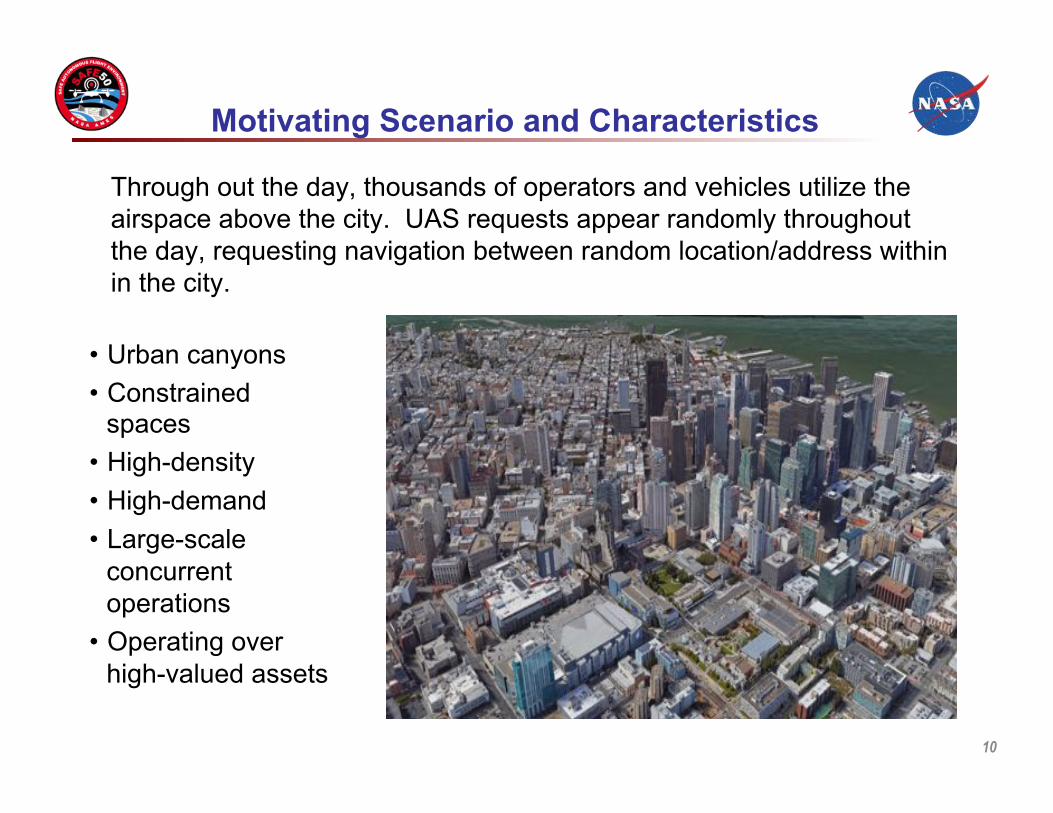
Motivating Scenario and Characteristics
10
Through out the day, thousands of operators and vehicles utilize the airspace above the city. UAS requests appear randomly throughout the day, requesting navigation between random location/address within in the city.
• Urban canyons • Constrained
spaces • High-density • High-demand • Large-scale
concurrent operations
• Operating over high-valued assets

Scope and Definitions
• Routine Operations • Small Unmanned Aerial Systems (UAS)
– Mass up to 25 kg to 150 kg * – Airspeed up to 40 m/s *
• Low-Altitude Operations – Altitude up to 200m or 400m **
• High-Density Urban Environments – “Non-trivial density” of humans, human structures, infrastructure, and competing air
traffic – Includes residential/commercial/high-rise buildings, towers, roads, bridges,
railways, manned aircraft (particularly rotorcraft), and other UAS – Density metrics to be defined, may include
• Population density greater than 1,000 people per square mile *** • Perhaps a minimum threshold UAS capacity per city block, such as 10 UAS
per city block
11
NASA UAS Classification Matrix*
Type Model or sUAS sUAS UAS
Category I (1) II (2) III (3)
Weight Limit ≤ 25 kg 25-150 kg > 150 kg
Airspeed Limit ≤ 40 m/s ≤ 100 m/s > 100 m/s
* per NASA NPR 7900.3C, Appendix I ** per U. S. Class G Airspace, typ. below 700ft/1200ft *** per Geographic Areas Reference Manual (GARM), U.S. Census Bureau, 1994

Challenges for High-Density Urban Operations
• Flight operations occur almost entirely beyond RF communications line-of-sight from ground operators to the vehicle. Limited point-to-point or satellite line-of-site. Need for Autonomy.
• Atmospheric uncertainties may have major impact on safety.
• Flight operations occur in a GPS-denied (or at-best a GPS-degraded) environment. Limited satellite line-of-site.
• Obstacles and hazards are not known with certainty ahead of time. Autonomous onboard see-and-avoid may an onboard vehicle requirement.
• Vehicle system failures has major impact on safety (high failure rates, single-string architectures).
• Real-time ground-based surveillance is not easily accomplished. Separation assurance may be an onboard vehicle autonomy requirement.
12

SAFE50 Vehicle Autonomy Requirements
13
Dynamic Ground Objects (DGO)
Static Ground Objects (SGO)
Other Aircraft Detect, Operate-Near, and Avoid-
Endangering SGOs
Detect, Operate-Near, and Avoid-Endangering
DGOs
Hazard Footprint Awareness, Risk Minimization/Avoidance,
Health Monitoring
Detect, Operate-Near, Avoid-Endangering
Other Aircraft UAS
Environment Challenges
Atmospheric Uncertainty
Failures and Contingencies
Degraded RF, SAT-COM, GPS
Winds and microbursts
Avoid endangering objects in environment.
• Detect : equivalent to ‘see’ or ‘sense’, cooperative or noncooperative, technology limits, SWaP constraints, cost implications
• Operate-Near : more stringent than ‘avoid’ • Avoid-Endangering : responsibility of risk and damage assigned to vehicles and operators

Tall-Poles and Research Focus
• Detection of objects (static, dynamic, other air vehicles) • Classification of objects (as needed to satisfy requirements) • Relative control to objects • Decision making under uncertainty • Resilience to wind gusts and micro-weather effects • Resilience to onboard failures • Risk minimizing nominal/off-nominal control • Alternative/augmentations to GNSS-derived position, navigation,
and timing
14

Approach

16 sUAV incident
High velocity region
1. UrbanScape Wind Uncertainties
2. GPS Denied/Degraded
3. Static/Dynamic Obstacles
Research Challenges
17
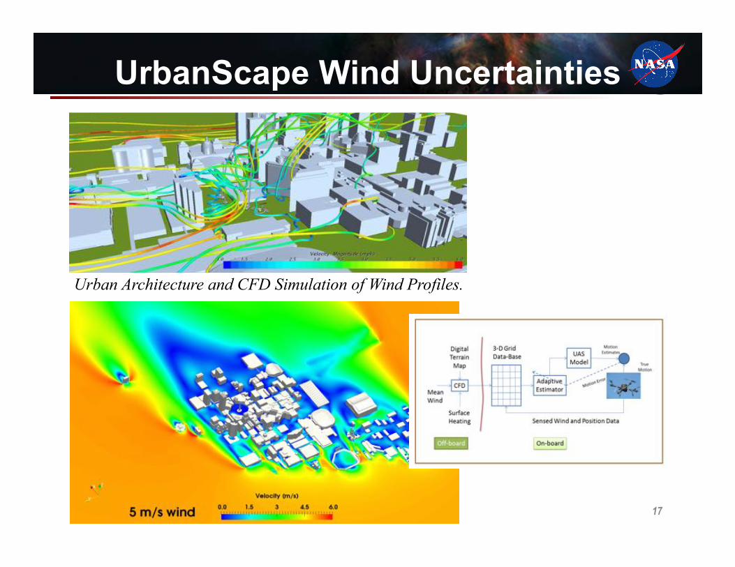
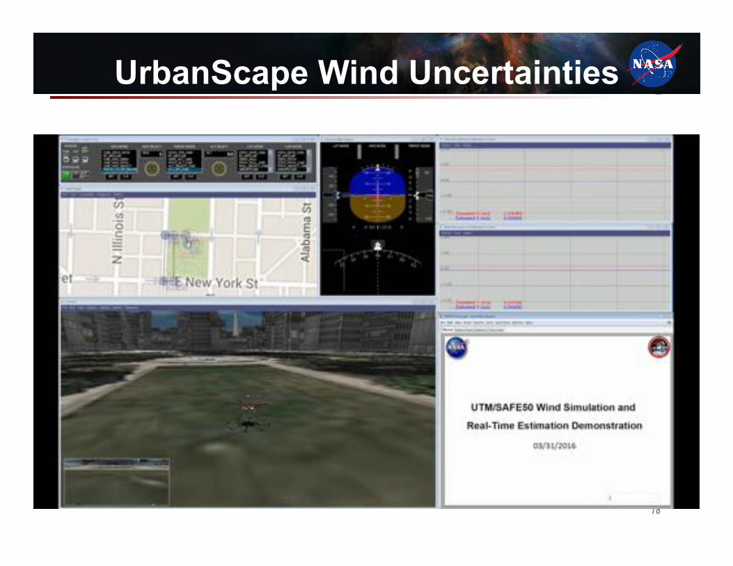
UrbanScape Wind Uncertainties
Urban Architecture and CFD Simulation of Wind Profiles.
18
UrbanScape Wind Uncertainties

GPS Denied/Degraded Navigation
19

20
Powerline Identification and Reconstruction. Raw LiDAR point clouds (left), voxel processing (middle), reconstructed powerlines (right), at 20m (top)
LiDAR Data and Voxel Representation
Static/Dynamic Obstacles
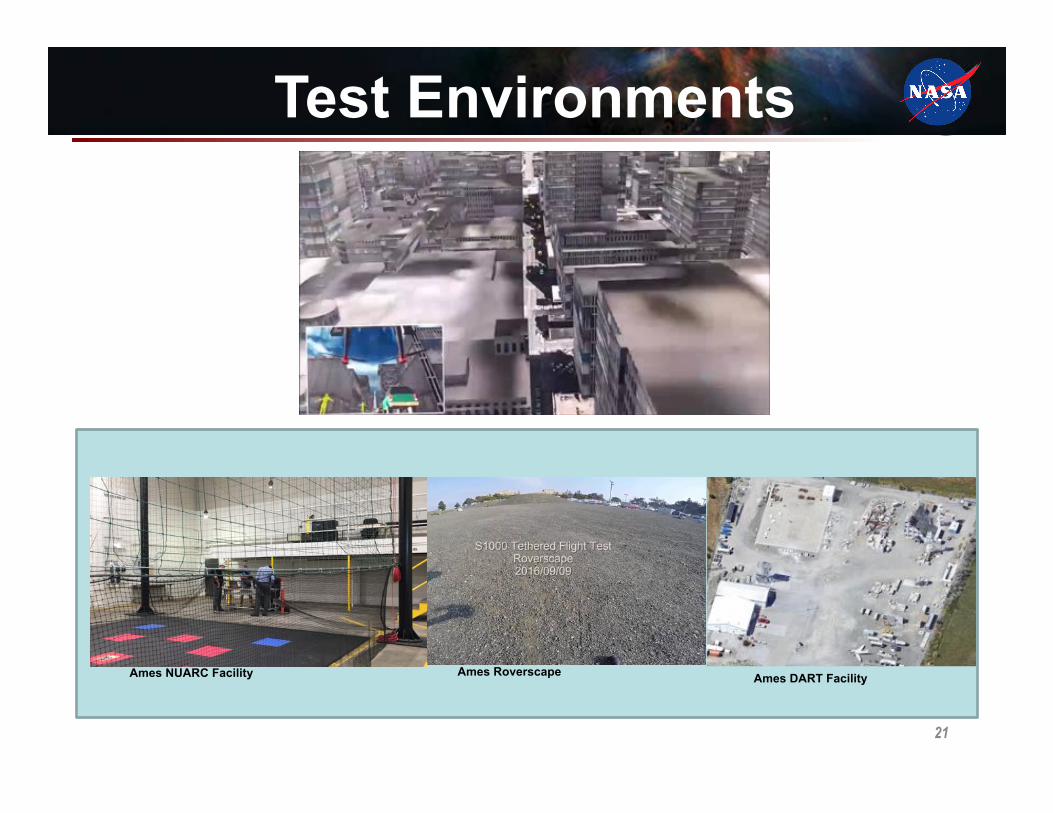
Test Environments
Ames Roverscape Ames DART Facility Ames NUARC Facility
21

Stall Recovery Guidance NASA-DLRmee3ngonUnmannedAircraIresearchtopics
StefanSchuet,JohnKaneshige,ThomasLombaerts,KimberleeShish,VahramStepanyan,GordonHardy,
PeterRobinsonNASAAmesResearchCenter,Moffe_Field

Structure
• Introduc+on• Guidancestrategies• Display• Simula+onresults• Twoimplementa+onstages
23/9Intro–Guidancestrategies–Display–Results–Implementa+on

Introduc4on • Loss of control in flight remains the most
frequent primary cause of accidents
• Stall related accidents: Colgan Air 3407, AirAsia 8501, XL Airways Germany 888T, Air Algerie 5017, Air France AF447,…
CAST studies: • Effective Upset Prevention and Recovery Training • Airplane State Awareness by aircrew (SE207)
• Algorithms and display strategies to provide control guidance for recovery from approach-to-stall or stall
24/9Intro–Guidancestrategies–Display–Results–Implementa+on

Introduc4on
Researchsubtopics,basedonCASTdirec+vesonsafetyenhancements:1. Upsetpreven3on
• Adap+vesafeflightenvelopees+ma+on• Autoflighttrajectorypredic+onandaler+ng• Adap+veenvelopeprotec+on
2. Upsetrecovery1. Stallrecoveryguidance currentresearch 2. Unusualabtuderecovery
Previousworkpublishedintheliterature:adap+veenvelopees+ma+on(AIAA-2013-4618/AIAA-2014-0268/AIAA-2015-1546)andprotec+on(AIAA-2015-1113/AIAA-2016-0093)
orde
rofp
riori+
es
previousresearch(2012-2015)
25/9Intro–Guidancestrategies–Display–Results–Implementa+on

Sequence of events for stall recovery
auralwarning,s+ckshaker,lowspeedbuffe+ng
∆h
onsettostall stalloccurrence stallrecovery
accelera+ngdive pitchup outofstall
Decreasingairspeed,increasingangleofa_ack
Speedbelowstallspeed,alphaexceedsstallvalue
Tradeal+tudeforspeed,poten+al→kine+cenergy
Transi+ontolevelflight,avoidingsecondarystallsoroverstressingstructure
Establishlevelflightorclimb
FAAstallrecoverytemplate:
1. Disconnectautopilotandautothro_le/autothrust
2. Nosedownun+lstallindica+onseliminated,
3. Bankwingslevel,4. Applythrustasneeded5. Retractspeedbrakes
andspoilers
6. Returntothedesiredflightpath
26/9Intro–Guidancestrategies–Display–Results–Implementa+on

Guidance strategies
Display
27/9
3strategiesunderconsidera+on:• Fastmodelpredic+vecontrol(AIAA-2017-1513)• Energybasedguidance(AIAA-2017-1021)• Constrainedcontrolapproach(AIAA-2016-0878)
Intro–Guidancestrategies–Display–Results–Implementa+on

Simula4on results
28/9
Angleofa_ackandcalibratedairspeed Energytransfers
Intro–Guidancestrategies–Display–Results–Implementa+on

Two implementa4on stages
AdvancedControlsTechnologies(ACT)lab
Ver3calMo3onSimulator(VMS)
29/9
Fall2016 Spring2017
Intro–Guidancestrategies–Display–Results–Implementa3on
Stall Recovery Guidance NASA-DLRmee3ngonUnmannedAircraIresearchtopics
StefanSchuet,JohnKaneshige,ThomasLombaerts,KimberleeShish,VahramStepanyan,GordonHardy,
PeterRobinsonNASAAmesResearchCenter,Moffe_Field

31
Generic Transport Model (GTM) with VCCTEF
Milestones1. Complete an initial multi-objective optimization study with aeroelastic finite-
element wing model coupled with longitudinal flight dynamic model, and subject to appropriate constraints.
2. Complete an initial robust control and distributed parameter control system design for coupled aircraft dynamics with aeroelastic wing structures to suppress fluttering motion.
Milestones: Aeroelastic Stability Augmentation/Flutter Suppression Control
National Aeronautics and Space Administration
Flight Controls for Flexible Air VehiclesPreparedby
SeanSweiandKennethCheungNASAAmesResearchCenter
incollaborationwith
NASA,MIT,MichiganStateU.,UCSC,U.ofAlabama
March14,2017

32
Outline
u Mission Adaptive Digital Aerostructure Technologies (MADCAT)
u Linear Parameter Varying (LPV) Modeling & ControlsØ Model AlignmentØ Adaptive Grid Step Size Determination
N719NU
MADCATv0
!
!CoordinatedTurn
Levelflight
OPTIMALWINGSHAPINGCONTROL

33
Mission Adaptive Digital Aerostructure Technologies (MADCAT)
§ Developarevolutionaryaerostructureconceptforfutureairvehiclesbycombining:Ø lattice-baseddiscrete/digitalconstructionapproachØ multi-objectiveoptimal8lightcontrols
ComponentDevelopment DigitalConstruction PerformanceAssessment(windtunneltests)

34
Mission Adaptive Digital Aerostructure Technologies (MADCAT)
PerformanceAssessment:MADCATv0FlightTests
N719NU
35
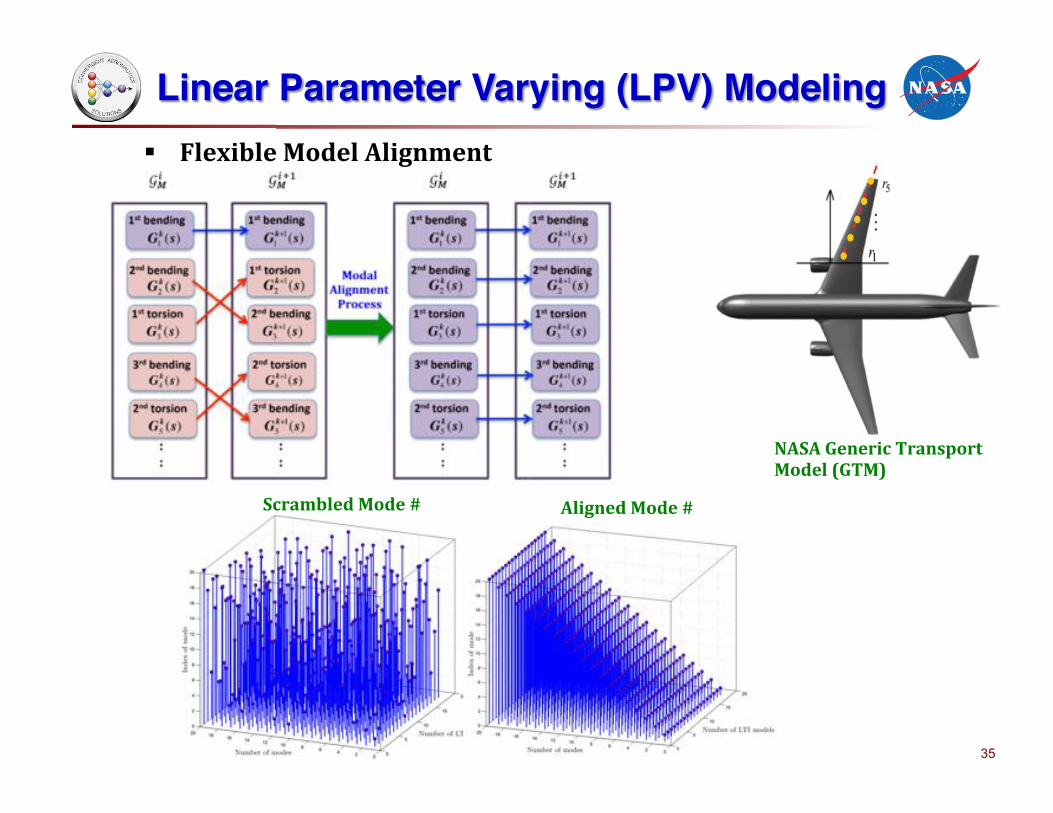
Linear Parameter Varying (LPV) Modeling§ FlexibleModelAlignment
ScrambledMode# AlignedMode#
NASAGenericTransportModel(GTM)

36
Linear Parameter Varying (LPV) Modeling§ AdaptiveGridStepSizeDetermination
Gji (s)
2−σ
2= Gj
i (s+σ )2
2
Note:σ-shiftedH2-norm,denotedbyH2-σ-norm,isde8inedby

37
Switch LPV Controls
Schedulingparameterdivision
ControlDesignObjectives:SequentiallydesignafamilyofLPVcontrollers,suchthat:1)theclosed-loopsystemsarestable;2)thecontrollersswitchsmoothlybetweenneighboringcontrollers;3)theClightperformancesareimproved.
LMICharacterization
§ SequentialdesignofhysteresisswitchingLPVcontrollers

38
Switching LPV Controls§ SequentialhysteresisswitchingLPVcontrollers
Schedulingparameterdivision
ControlObjective:SequentiallydesignafamilyofLPVcontrollerssuchthat:1)theclosed-loopsystemsarestable;2)thecontrollersswitchsmoothlybetweenneighboringcontrollers;3)theperformancesareimproved.
LMICharacterization
Thank You!
650-604-0314

39
Thank You