Embed Size (px)
Citation preview

ADVANCED COMMUNICATIONS & SENSING
Rev 1 – 25th July 2011 1 www.semtech.com
SX8677/SX8678 Haptics Enabled Multitouch 4/5-Wire
Resistive Touchscreen Controller with Proximity Sensing
GENERAL DESCRIPTION
The SX8677 and SX8678 belong to a family of high performance haptics enabled multitouch 4/5-wire resistive touch screen controller with proximity detection, optimized for hand held applications such as mobile phones, portable music players, game machines, point-of-sales terminal and other consumer and industrial applications. They feature a wide input supply range from 2.3V to 3.6V.
The controller computes touch screen X-Y coordinates and touch pressure with a precision, low power 12-bit analog-digital converter. On-chip data averaging processing algorithms can be activated to reduce host activity and suppress system noise. The processing core features low power modes which intelligently minimize current in operation as well as in automatic shut-down.
Multitouch feature enables detection of 2 fingers on the touchscreen and several gestures like rotation and pinch/stretch.
A capacitive proximity detection circuit has been integrated into the SX8677 to enable host controlled power management for battery applications. Proximity detection above 5 cm is possible using either the resistive touch screen as the sensor or with a single conductive plate, with communication to the host via the serial interface.
The SX8677 and SX8678 also integrate a haptics motor driver for Linear Resonant Actuator (LRA) and Eccentric Rotating Mass (ERM) micro motors with up to 250mA drive current. Haptics control can be performed using either an external PWM signal or the I2C serial interface, providing simple host interfacing and minimizing its I/O requirement. The SX8677/78 supports Immersion TouchSense® 3000 haptic control software for high quality touch feedback.
Integrated very high ESD protection, of up to ±15kV on display inputs not only saves cost and board area, but also increases application reliability.
The three devices have an ambient operating temperature range of -40°C to +85°C, and are offere d in both a 4mm x 4mm, 20-lead QFN package and 2.07mm x 2.07mm 19-lead CSP package for space-conscious applications.
TYPICAL APPLICATIONS • Game Machines, Portable Music Players • Mobile Phones • DSC, DVR, Phones • POS/POI Terminals • Touch-Screen Monitors
ORDERING INFORMATION
KEY PRODUCT FEATURES • Low Voltage Operation
2.3V to 3.6V Supply Integrated Low Drop Out (LDO) Regulator
• Low Power Consumption [email protected] 8ksps (ESR) 0.4uA Shut-Down Current
• 4/5-Wire Touchscreen Interface Precision, Ratiometric 12-bit ADC Up to 5000 (X-Y) coordinates/second (c/s) Programmable Digital Filtering/Averaging Touch Pressure Measurement (4-Wire) Programmable Operating Mode (Manual,
Pen Detect, Pen Trigger) • Capacitive Proximity Sensing (SX8677)
No Additional Components Required Uses Resistive Touchscreen or a Simple
Conductive Area as the Sensor >5 cm Detection Distance 8uA @ 200ms Scan Period Fully Programmable (Sensitivity, etc)
• Haptics Driver for LRA and ERM (SX8677/78) Supports Immersion TouchSense® 3000
haptic control software Haptics Waveform Generation Control (I2C
or PWM Input) Short Circuit Protection Early Warning and Over-Temperature
Monitoring and Protection • 400kHz I2C Serial Interface • Several Host Operating Modes Available
Maskable Interrupt Output (NIRQ) Real-time Events Monitoring (AUX1-3) Polling (I2C)
• Hardware, Software, and Power-On Reset • -40°C to +85°C Operating Temperature Range • 15kV HBM & IEC ESD Protection • Small Footprint Packages • Pb & Halogen Free, RoHS/WEEE compliant
Part Number Package Marking SX8677IWLTRT QFN-20 SX8677ICSTRT WLCSP-19
RNT2
SX8678IWLTRT QFN-20 SX8678ICSTRT WLCSP-19
RP9X
SX8674EVK Evaluation Kit -
I2C
NRST
NIRQ
SX8677 Host Controller
MULTITOUCH CONTROL
PROXIMITY SENSING
M
HAPTICS DRIVER

ADVANCED COMMUNICATIONS & SENSING
Rev 1 – 25th July 2011 2 www.semtech.com
SX8677/SX8678 Haptics Enabled Multitouch 4/5-Wire
Resistive Touchscreen Controller with Proximity Sensing
Table of Contents
GENERAL DESCRIPTION ..................................................................................................................... 1
TYPICAL APPLICATIONS ..................................................................................................................... 1
ORDERING INFORMATION................................................................................................................... 1
KEY PRODUCT FEATURES.................................................................................................................. 1
1 GENERAL DESCRIPTION ............................................................................................................ 4
1.1 Marking Information 4 1.1.1 SX8677 4 1.1.2 SX8678 4
1.2 Pin Diagrams 5 1.2.1 QFN Package 5 1.2.2 CSP Package 5
1.3 Pin Description 6 1.4 Block Diagram 6
2 ELECTRICAL CHARACTERISTICS............................................................................................... 8
2.1 Absolute Maximum Ratings 8 2.2 Thermal Characteristics 8 2.3 Electrical Specifications 8
3 TYPICAL OPERATING CHARACTERISTICS ............................................................................... 11
4 TOUCHSCREEN INTERFACE..................................................................................................... 12
4.1 Introduction 12 4.2 Coordinates Measurement 13
4.2.1 4-wire Touchscreen 13 4.2.2 5-wire Touchscreen 14
4.3 Pressure Measurement (4-wire only) 14 4.3.1 Bias Time (POWDLY) 15
4.4 Pen Detection 15 4.5 Multitouch Measurement (4-wire only) 16 4.6 Digital Processing 17 4.7 Host Operation 18
4.7.1 Overview 18 4.7.2 Manual Mode (MAN) 18 4.7.3 Pen Detect Mode (PENDET) 20 4.7.4 Pen Trigger Mode (PENTRG) 20 4.7.5 Maximum Throughput vs. TOUCHRATE setting 21
5 PROXIMITY SENSING INTERFACE (SX8677) ............................................................................ 23
5.1 Introduction 23 5.2 Analog Front-End (AFE) 24
5.2.1 Capacitive Sensing Basics 24 5.2.2 AFE Block Diagram 25 5.2.3 Capacitance-to-Voltage Conversion (C-to-V) 26 5.2.4 Shield Control 26 5.2.5 Offset Compensation 26 5.2.6 Analog-to-Digital Conversion (ADC) 27
5.3 Digital Processing 27 5.3.1 Overview 27 5.3.2 PROXRAW Update 28 5.3.3 PROXUSEFUL Update 29 5.3.4 PROXAVG Update 30

ADVANCED COMMUNICATIONS & SENSING
Rev 1 – 25th July 2011 3 www.semtech.com
SX8677/SX8678 Haptics Enabled Multitouch 4/5-Wire
Resistive Touchscreen Controller with Proximity Sensing
5.3.5 PROXDIFF Update 32 5.3.6 PROXSTAT Update 32
5.4 Host Operation 33 5.4.1 General Description 33 5.4.2 Proximity Sensing vs Touch Operations 33 5.4.3 Minimum Scan Period (i.e. PROXSCANPERIOD) 35
6 HAPTICS INTERFACE (SX8677/78) .......................................................................................... 36
6.1 Introduction 36 6.2 ERM Load 36
6.2.1 Introduction 36 6.2.2 PWM Mode 37 6.2.3 I2C Mode 37
6.3 LRA Load 37 6.3.1 Introduction 37 6.3.2 PWM Mode 38 6.3.3 I2C Mode 38
6.4 Short-Circuit Protection 38
7 TEMPERATURE SENSOR.......................................................................................................... 39
8 INTERRUPT (NIRQ) .................................................................................................................. 40
8.1 Introduction 40 8.2 Registers Overview 40
8.2.1 RegIrqMsk 40 8.2.2 RegIrqSrc 40 8.2.3 RegStat 40
8.3 Host Procedure 40
9 AUXILIARY PINS (AUX1/AUX2/AUX3)...................................................................................... 41
10 RESET...................................................................................................................................... 42
10.1 Hardware (POR and NRST) 42 10.2 Software (RegReset) 42 10.3 ESD Event (RESETSTAT) 42
11 I2C INTERFACE ........................................................................................................................ 43
11.1 Introduction 43 11.2 I2C Address 43 11.3 Write Register 43 11.4 Read Register 44 11.5 Write Command (Touchscreen Interface) 44 11.6 Read Channel (Touchscreen Interface) 45
12 REGISTERS DETAILED DESCRIPTION ...................................................................................... 47
13 APPLICATION INFORMATION ................................................................................................... 59
13.1 Typical Application Circuit 59 13.2 External Components Recommended Values 59 13.3 Multitouch Gestures 59
13.3.1 Pinch/Stretch 59 13.3.2 Rotate 60
14 PACKAGING INFORMATION ..................................................................................................... 61
14.1 QFN Package 61 14.2 CSP Package 62
ADVANCED COMMUNICATIONS & SENSING
Rev 1 – 25th July 2011 4 www.semtech.com
SX8677/SX8678 Haptics Enabled Multitouch 4/5-Wire
Resistive Touchscreen Controller with Proximity Sensing
1 GENERAL DESCRIPTION
1.1 Marking Information
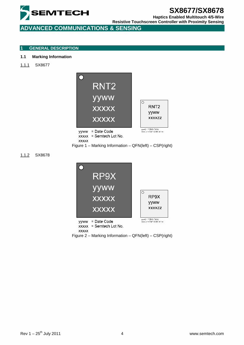
1.1.1 SX8677
Figure 1 – Marking Information – QFN(left) – CSP(right)
1.1.2 SX8678
Figure 2 – Marking Information – QFN(left) – CSP(right)

ADVANCED COMMUNICATIONS & SENSING
Rev 1 – 25th July 2011 5 www.semtech.com
SX8677/SX8678 Haptics Enabled Multitouch 4/5-Wire
Resistive Touchscreen Controller with Proximity Sensing
1.2 Pin Diagrams
1.2.1 QFN Package
Figure 3 – Pin Diagram – QFN
1.2.2 CSP Package
Figure 4 – Pin Diagram - CSP
ADVANCED COMMUNICATIONS & SENSING
Rev 1 – 25th July 2011 6 www.semtech.com
SX8677/SX8678 Haptics Enabled Multitouch 4/5-Wire
Resistive Touchscreen Controller with Proximity Sensing
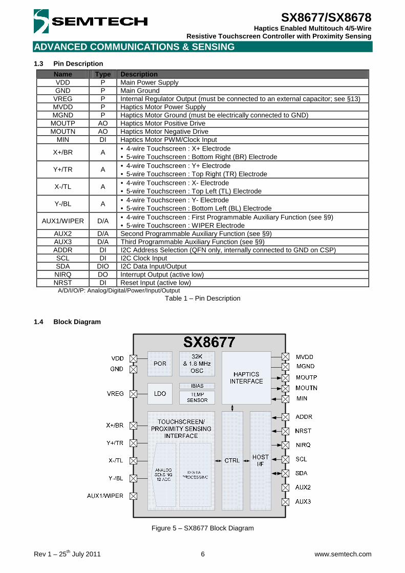
1.3 Pin Description
Name Type Description VDD P Main Power Supply GND P Main Ground
VREG P Internal Regulator Output (must be connected to an external capacitor; see § 13) MVDD P Haptics Motor Power Supply MGND P Haptics Motor Ground (must be electrically connected to GND)
MOUTP AO Haptics Motor Positive Drive MOUTN AO Haptics Motor Negative Drive
MIN DI Haptics Motor PWM/Clock Input
X+/BR A • 4-wire Touchscreen : X+ Electrode • 5-wire Touchscreen : Bottom Right (BR) Electrode
Y+/TR A • 4-wire Touchscreen : Y+ Electrode • 5-wire Touchscreen : Top Right (TR) Electrode
X-/TL A • 4-wire Touchscreen : X- Electrode • 5-wire Touchscreen : Top Left (TL) Electrode
Y-/BL A • 4-wire Touchscreen : Y- Electrode • 5-wire Touchscreen : Bottom Left (BL) Electrode
AUX1/WIPER D/A • 4-wire Touchscreen : First Programmable Auxiliary Function (see § 9) • 5-wire Touchscreen : WIPER Electrode
AUX2 D/A Second Programmable Auxiliary Function (see § 9) AUX3 D/A Third Programmable Auxiliary Function (see § 9) ADDR DI I2C Address Selection (QFN only, internally connected to GND on CSP) SCL DI I2C Clock Input SDA DIO I2C Data Input/Output NIRQ DO Interrupt Output (active low) NRST DI Reset Input (active low)
A/D/I/O/P: Analog/Digital/Power/Input/Output Table 1 – Pin Description
1.4 Block Diagram
Figure 5 – SX8677 Block Diagram

ADVANCED COMMUNICATIONS & SENSING
Rev 1 – 25th July 2011 7 www.semtech.com
SX8677/SX8678 Haptics Enabled Multitouch 4/5-Wire
Resistive Touchscreen Controller with Proximity Sensing
Figure 6 – SX8678 Block Diagram
ADVANCED COMMUNICATIONS & SENSING
Rev 1 – 25th July 2011 8 www.semtech.com
SX8677/SX8678 Haptics Enabled Multitouch 4/5-Wire
Resistive Touchscreen Controller with Proximity Sensing
2 ELECTRICAL CHARACTERISTICS
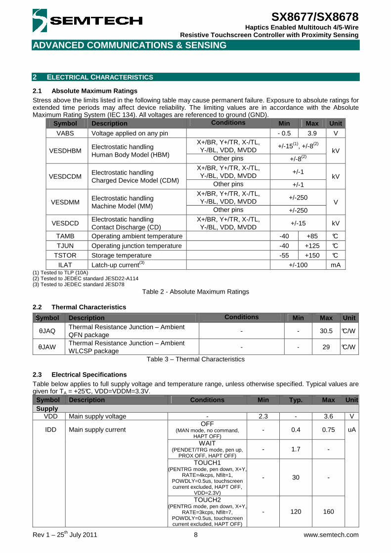
2.1 Absolute Maximum Ratings Stress above the limits listed in the following table may cause permanent failure. Exposure to absolute ratings for extended time periods may affect device reliability. The limiting values are in accordance with the Absolute Maximum Rating System (IEC 134). All voltages are referenced to ground (GND).
Symbol Description Conditions Min Max Unit
VABS Voltage applied on any pin - 0.5 3.9 V X+/BR, Y+/TR, X-/TL, Y-/BL, VDD, MVDD
+/-15(1), +/-8(2) VESDHBM
Electrostatic handling Human Body Model (HBM) Other pins +/-8(2)
kV
X+/BR, Y+/TR, X-/TL, Y-/BL, VDD, MVDD
+/-1 VESDCDM
Electrostatic handling Charged Device Model (CDM) Other pins +/-1
kV
X+/BR, Y+/TR, X-/TL, Y-/BL, VDD, MVDD
+/-250 VESDMM
Electrostatic handling Machine Model (MM) Other pins +/-250
V
VESDCD Electrostatic handling Contact Discharge (CD)
X+/BR, Y+/TR, X-/TL, Y-/BL, VDD, MVDD
+/-15 kV
TAMB Operating ambient temperature -40 +85 °C
TJUN Operating junction temperature -40 +125 °C
TSTOR Storage temperature -55 +150 °C
ILAT Latch-up current(3) +/-100 mA (1) Tested to TLP (10A) (2) Tested to JEDEC standard JESD22-A114 (3) Tested to JEDEC standard JESD78
Table 2 - Absolute Maximum Ratings
2.2 Thermal Characteristics
Symbol Description Conditions Min Max Unit
θJAQ Thermal Resistance Junction – Ambient QFN package
- - 30.5 °C/W
θJAW Thermal Resistance Junction – Ambient WLCSP package
- - 29 °C/W
Table 3 – Thermal Characteristics
2.3 Electrical Specifications Table below applies to full supply voltage and temperature range, unless otherwise specified. Typical values are given for TA = +25°C, VDD=VDDM=3.3V. Symbol Description Conditions Min Typ. Max Unit Supply
VDD Main supply voltage - 2.3 - 3.6 V OFF
(MAN mode, no command, HAPT OFF)
- 0.4 0.75
WAIT (PENDET/TRG mode, pen up,
PROX OFF, HAPT OFF) - 1.7 -
TOUCH1 (PENTRG mode, pen down, X+Y,
RATE=4kcps, Nfilt=1, POWDLY=0.5us, touchscreen current excluded, HAPT OFF,
VDD=2.3V)
- 30 -
IDD Main supply current
TOUCH2 (PENTRG mode, pen down, X+Y,
RATE=3kcps, Nfilt=7, POWDLY=0.5us, touchscreen current excluded, HAPT OFF)
- 120 160
uA

ADVANCED COMMUNICATIONS & SENSING
Rev 1 – 25th July 2011 9 www.semtech.com
SX8677/SX8678 Haptics Enabled Multitouch 4/5-Wire
Resistive Touchscreen Controller with Proximity Sensing
Symbol Description Conditions Min Typ. Max Unit PROX
(PENDET/TRG mode, pen up, TOUCHRATE=80cps, PROX ON,
SCANPERIOD=200ms, HIGHIM=ON,
SENSITIVITY=Max, FREQ=150kHz, BOOST=OFF,
HAPT OFF)
- 8 20
HAPT (MAN mode, no command,
LRA-PWM mode, MIN= 44.8kHz/50%, GAIN = Max,
BW = 100, MOUTP/N floating, Squelch=011)
- 115 145
MVDD Haptics supply voltage - VDD - 3.6 V OFF - 0.01 1 µA
MIDD Haptics supply current SQUELCH
(LRA-PWM mode, MIN= 44.8kHz/50%, GAIN = Max,
BW = 100, MOUTP/N floating, Squelch=011)
- 6 10 µA
Digital I/Os (ADDR, SCL, SDA, NRST, NIRQ, AUX1, AUX2, AUX3, MIN) SCL, SDA, NRST 0.8*VDD - 3.6 VIH High level input voltage
Other pins 0.8*VDD - VDD+0.2 V
VIL Low level input voltage - -0.3 - 0.8 V ILEAK Input leakage current - -1 - 1 µA
CI Input capacitance - - 5 - pF VOH High level output voltage IOH = 4mA 0.8*VDD - - V VOL Low level output voltage IOL = 4mA - - 0.4 V
VPULL External pull-up voltage SCL, SDA, NRST, NIRQ - - 3.6 V Haptics Interface
IDRV Maximum drive current (MOUTP/MOUTN) MVDD = 3.6V - 250 - mA
VOFF Output squelch differential error (from 0V ideal)
LRA or ERM, PWM or I2C, AmplitudeCode within squelch range, GAIN = Max, BW = 100,
MOUTP/N floating, Squelch=011
0(1) 0 0(1) mV
VERR Output differential error (from 1.135V ideal)
LRA or ERM, I2C, AmplitudeCode = +127 (Max)
GAIN = Min, BW = 100, MOUTP/N floating
125(2) 0 125(2) mV
VDRV Drive voltage (MOUTP/MOUTN) - - - VDDM V
VDROP Drop voltage (MOUTP/MOUTN) From MVDD/MGND, @250mA - - 150 mV
ISHORT Short-circuit detection current Measured @MIDD - 300 - mA
FMINC Motor input (MIN) frequency in I2C mode 40-60% duty cycle - - 50 MHz
HAPTRANGE = 0 12.8 - 25.6 kHz FMINP Motor input (MIN) frequency in
PWM mode HAPTRANGE = 1 25.6 - 51.2 kHz
DCMIN Motor input (MIN) duty cycle in PWM mode 2 - 98 %
TWRNG Warning temperature - 120 - TALRM Alarm temperature
Junction temperature - 155 -
°C
Touchscreen Interface ARES ADC resolution 12 - - bits AOFF ADC offset - ± 1 - AGE ADC gain error At full scale - 0.5 - ADNL ADC differential non-linearity - ± 1 - AINL ADC integral non-linearity - ± 1.5 -
LSB
RBIAS Biasing resistance - 5 - Ω Proximity Sensing Interface
CDC External capacitance to be compensated - - - 300 pF
tPROX Scan period (reaction time) Programmable - 200 - ms

ADVANCED COMMUNICATIONS & SENSING
Rev 1 – 25th July 2011 10 www.semtech.com
SX8677/SX8678 Haptics Enabled Multitouch 4/5-Wire
Resistive Touchscreen Controller with Proximity Sensing
Symbol Description Conditions Min Typ. Max Unit Reset
VPOR Power-On-Reset voltage Cf. § 10 - 1.3 - V tRESET Reset time after POR Cf. § 10 - - 1 ms tPULSE Reset pulse from host uC Cf. § 10 1 - - us
I2C Interface
fSCL SCL clock frequency - - - 400 kHz
tHD;STA Hold time (repeated) START condition - 0.6 - - µs
tLOW LOW period of the SCL clock - 1.3 - - µs tHIGH HIGH period of the SCL clock - 0.6 - - µs
tSU;STA Set-up time for a repeated START condition - 0.6 - - µs
tHD;DAT Data hold time - 0 - - µs tSU;DAT Data set-up time - 100 - - ns
tr Rise time of both SDA and SCL - 20+0.1Cb - 300 ns tf Fall time of both SDA and SCL - 20+0.1Cb - 300 ns
tSU;STO Set-up time for STOP condition - 0.6 - - µs
tBUF Bus free time between a STOP and START condition - 1.3 - - µs
Cb Capacitive load for each bus line - - - 400 pF
tSP Pulse width of spikes suppressed by the input filter
Up to 0.3xVDD from GND, down to 0.7xVDD
from VDD 50 - - ns
Miscellaneous FOSCL Low frequency internal oscillator - - 32 - kHz FOSCH High frequency internal oscillator - - 1.8 - MHz
(1) Guaranteed by design.
(2) PWM mode can introduce an additional error of 2.5% of full scale.
Table 4 – Electrical Specifications

ADVANCED COMMUNICATIONS & SENSING
Rev 1 – 25th July 2011 11 www.semtech.com
SX8677/SX8678 Haptics Enabled Multitouch 4/5-Wire
Resistive Touchscreen Controller with Proximity Sensing
3 TYPICAL OPERATING CHARACTERISTICS Conditions as defined in § 2.3, TA = +25°C, VDD=VDDM=3.3V unless otherwise specified.
IDD_OFF vs VDD vs TEMP
2.00E-07
2.20E-07
2.40E-07
2.60E-07
2.80E-07
3.00E-07
3.20E-07
3.40E-07
3.60E-07
3.80E-07
4.00E-07
2.3 2.5 2.7 2.9 3.1 3.3 3.5
VDD(V)
IDD
(A) 25°C
85°C
-40°C
IDD_WAIT vs VDD vs TOUCHRATE
0
1
2
3
4
5
6
7
8
2.3 2.4 2.5 2.6 2.7 2.8 2.9 3.0 3.1 3.2 3.3 3.4 3.5 3.6
VDD(V)
IDD
(uA
)
10cps
80cps
2000cps
5000cps
IDD_PROX vs SCANPERIOD vs SENSITIVITY
0
10
20
30
40
50
60
70
80
0 100 200 300 400 500 600 700 800
SCANPERIOD(ms)
IDD
_PR
OX
(uA
)
0(Min)
5
7(Max)
IDD_HAPT vs VDD vs TEMP
0.0001
0.00011
0.00012
0.00013
0.00014
0.00015
0.00016
0.00017
0.00018
0.00019
0.0002
2.3 2.5 2.7 2.9 3.1 3.3 3.5
VDD(V)
IDD
(A) 25°C
85°C
-40°C
MIDD_OFF vs MVDD vs TEMP
0.00E+00
5.00E-09
1.00E-08
1.50E-08
2.00E-08
2.50E-08
3.00E-08
3.50E-08
4.00E-08
4.50E-08
5.00E-08
2.3 2.5 2.7 2.9 3.1 3.3 3.5
MVDD(V)
MID
D(A
) 25°C
85°C
-40°C
MIDD_SQUELCH vs MVDD vs TEMP
5.00E-06
6.00E-06
7.00E-06
8.00E-06
9.00E-06
1.00E-05
2.3 2.5 2.7 2.9 3.1 3.3 3.5
MVDD(V)
IDD
(A) 25°C
85°C
-40°C
VERR vs GAIN vs MVDD
0.02
0.03
0.04
0.05
0.06
0.07
0.08
0 1 2 3 4 5 6 7 8 9 10 11 12 13 14 15 GAIN
VOFF(V) 2.3V 3.3V 3.6V

ADVANCED COMMUNICATIONS & SENSING
Rev 1 – 25th July 2011 12 www.semtech.com
SX8677/SX8678 Haptics Enabled Multitouch 4/5-Wire
Resistive Touchscreen Controller with Proximity Sensing
4 TOUCHSCREEN INTERFACE
4.1 Introduction The purpose of the touchscreen interface is to measure and extract touch information like coordinates and pressure. This is done in two steps, first an ADC measures the analog signal coming from the screen, and then digital processing is performed to consolidate the data. As illustrated below the chip’s touchscreen interface is compatible with both 4-wire and 5-wire touchscreens. Touchscreen type is defined by parameter TSTYPE.
Figure 7 – Touchscreen Interface Overview
A 4-wire resistive touch screen consists in two (resistive) conductive sheets separated by an insulator when not pressed. Each sheet is connected through 2 electrodes at the border of the sheet. When a pressure is applied on the top sheet, a connection with the lower sheet is established.
Figure 8 – 4-wire Touchscreen
A 5-wire resistive touch screen consists in two (resistive) conductive sheets separated by an insulator when not pressed. 4 electrodes are connected on the 4 corners of the bottom conductive sheet. They are referred as Top Left (TL), Top Right (TR), Bottom Left (BL) and Bottom Right (BR). The fifth wire (WIPER) is used for sensing the top sheet voltage. When a pressure is applied on the top sheet, a connection with the lower sheet is established.

ADVANCED COMMUNICATIONS & SENSING
Rev 1 – 25th July 2011 13 www.semtech.com
SX8677/SX8678 Haptics Enabled Multitouch 4/5-Wire
Resistive Touchscreen Controller with Proximity Sensing
Higher reliability and better endurance are the advantages of 5-wire touchscreens but they do not allow pressure measurement
Figure 9 – 5-wire Touchscreen
4.2 Coordinates Measurement
4.2.1 4-wire Touchscreen The electrode plates are internally connected through terminals X+, X- and Y+, Y- to an analog to digital converter (ADC) and a reference voltage (Vref). The resistance between the terminals X+ and X- is defined by Rxtot. Rxtot will be split in 2 resistors, R1 and R2, in case the screen is touched. Similarly, the resistance between the terminals Y+ and Y- is represented by R3 and R4. The connection between the top and bottom sheet is represented by the touch resistance (RT). In order to measure the Y coordinate, the top resistive sheet (Y) is biased with a voltage source (Vref). Resistors R3 and R4 determine a voltage divider proportional to the Y position of the contact point. Since the converter has a high input impedance, no current flows through R1 (and RT) so that the voltage X+ at the converter input is given by the voltage divider created by R3 and R4. The X coordinate is measured in a similar fashion with the bottom resistive sheet (X) biased to create a voltage divider by R1 and R2, while the voltage on the top sheet is measured through R3. The resistance RT is the resistance obtained when a pressure is applied on the screen. RT is created by the contact area of the X and Y resistive sheet and varies with the applied pressure.
Figure 10 – 4-wire Touchscreen Coordinates Measurement
The X and Y positions output by the ADC correspond to the formulas below:
Xpos 4095R2
R1 R2+---------------------⋅= Ypos 4095 R4
R3 R4+---------------------⋅=
4095 corresponds to the max output value of the ADC (12 bits => 212 – 1). For example, a touch in the center of the screen will output (Xpos, Ypos) = ~(2048, 2048)

ADVANCED COMMUNICATIONS & SENSING
Rev 1 – 25th July 2011 14 www.semtech.com
SX8677/SX8678 Haptics Enabled Multitouch 4/5-Wire
Resistive Touchscreen Controller with Proximity Sensing
4.2.2 5-wire Touchscreen 5-wire touchscreen coordinates measurement is performed similarly by biasing opposite corner pairs in either X or Y directions on the lower panel, and converting the voltage appearing on the wiper panel with the ADC.
Figure 11 – 5-wire Touchscreen Coordinates Measurement
The X and Y positions output by the ADC correspond to the formulas below:
Xpos 4095R2
R1 R2+---------------------⋅= Ypos 4095 R4
R3 R4+---------------------⋅=
4095 corresponds to the max output value of the ADC (12 bits => 212 – 1). For example, a touch in the center of the screen will output (Xpos, Ypos) = ~(2048, 2048)
4.3 Pressure Measurement (4-wire only) The pressure measurement consists in extracting the touch resistance RT via two additional setups z1 and z2 illustrated below. The smaller RT, the more common touched surface there is between top and bottom plates and hence the more “pressure” there is by the user.
Figure 12 – Pressure Measurement
The z1 and z2 values output by the ADC correspond to the formulas below:
z1 4095 R4R1 R4 RT+ +----------------------------------⋅= z2 4095 R4 Rt+
R1 R4 RT+ +----------------------------------⋅=
The X and Y total sheet resistance (Rxtot = R1+R2, Rytot = R3+R4) are known from the touch screen supplier. R4 is proportional to the Y coordinate and its value is given by the total Y plate resistance Rytot multiplied by the fraction of the Y position over the full coordinate range.

ADVANCED COMMUNICATIONS & SENSING
Rev 1 – 25th July 2011 15 www.semtech.com
SX8677/SX8678 Haptics Enabled Multitouch 4/5-Wire
Resistive Touchscreen Controller with Proximity Sensing
Rxtot R1 R2+=
Rytot R3 R4+=
R4 Rytot Ypos4095-------------⋅=
z2
Re-arranging z1 and z2 gives:
RT R4z2z1------ 1–⋅=
This finally results in:
RT Rytot Ypos4095------------- z2
z1------ 1–⋅ ⋅=
The touch resistance calculation above hence requires three channel measurements (Ypos, z2 and z1) and one specification data (Rytot). An alternative calculation method is using Xpos, Ypos, one z channel and both Rxtot and Rytot as shown in the next calculations. R1 is inversely proportional to the X coordinate:
R1 Rxtot 1 Xpos4095-------------–⋅=
Substituting R1 and R4 into z1 and rearranging terms gives:
RTRytot Y⋅ pos
4095---------------------------------
4095z1
------------ 1– Rxtot 1Xpos4095-------------–⋅–⋅=
Please note that the chip only outputs z1, z2, etc. The calculation of RT itself with the formulas above must be performed by the host.
4.3.1 Bias Time (POWDLY) In order to perform correct measurements, some time must be given for the touch screen to reach a proper Vref bias level before the conversion is actually performed. It is a function of the PCB trace resistance connecting the chip to the touchscreen and also the capacitance of the touchscreen. If tau is this RC time constant, then POWDLY duration must be programmed to 10 tau to reach 12 bits accuracy. Adding a capacitor from the touch screen electrodes to ground may also be used to minimize external noise (if the touchscreen is used as the proximity sensor, make sure you do not exceed the maximum capacitive load for required for proper proximity sensing operation). The low-pass filter created with the capacitor may increase settling time requirement. Therefore, POWDLY can be used to stretch the acquisition period and delay conversion appropriately. POWDLY can be estimated by the following formula:
PowDly 10 Rtouch Ctouch××=
4.4 Pen Detection The pen detection circuitry is used both to detect a user action and generate an interrupt or start an acquisition in PENDET and PENTRG mode respectively. Doing pen detection prior to conversion avoids feeding the host with dummy data and saves power. Pen detection is also used to disable and resume proximity sensing. For more details on pen detection usage please refer to § 4.7. A 4-wire touchscreen will be powered between X+ and Y- through a resistor RPNDT so no current will flow as long as no pressure is applied to the surface (see figure below). When a touch occurs, a current path is created bringing X+ to the level defined by the resistive divider determined by RPNDT and the sum of R1, RT and R4.

ADVANCED COMMUNICATIONS & SENSING
Rev 1 – 25th July 2011 16 www.semtech.com
SX8677/SX8678 Haptics Enabled Multitouch 4/5-Wire
Resistive Touchscreen Controller with Proximity Sensing
Figure 13 – 4-wire Touchscreen Pen Detection
When using a 5-wire touchscreen, the pen detection pull-up resistor RPNDT and digital comparator continue to monitor the X+/BR pin as in 4-wire mode. The top panel is grounded via the WIPER pin to provide the grounding path for a screen touch event. When a touch occurs, a current path is created and will bring BR to the level defined by the resistive divider determined by RPNDT and the sum of R1, RT and RW.
Figure 14 – 5-wire Touchscreen Pen Detection
RPNDT can be configured to 4 different values to accommodate different screen resistive values. RPNDT should be set to a value greater than 7x(Rxtot + Rytot), it is recommended to set it to max value. Pen detection uses a bias time of POWDLY/8 (digital comparator => less precision required vs analog conversion). Increasing POWDLY can improve the detection on panels with high resistance. A pen touch will set the PENSTAT bit of the RegStat register which will generate an interrupt if enabled in RegIrqMsk. A pen release will reset PENSTAT bit of the RegStat register which will generate an interrupt if enabled in RegIrqMsk.
4.5 Multitouch Measurement (4-wire only) SX8677/78 support up to two simultaneous touches on any standard 4-wire touchscreen. The simplified model for dual-touch is given in figure below.

ADVANCED COMMUNICATIONS & SENSING
Rev 1 – 25th July 2011 17 www.semtech.com
SX8677/SX8678 Haptics Enabled Multitouch 4/5-Wire
Resistive Touchscreen Controller with Proximity Sensing
Rxtot R1 R2 R3+ +=
Rytot R4 R5 R6+ += Figure 15 – Dual-touch Simplified Model
The two contacts create touch resistances Rt1 and Rt2 between the two layers of the touchscreen.
The SX8677/78 perform on-chip specific multitouch measurements which the host retrieves and processes with a specific software enabling the detection of the gestures described in § 13.3. For optimum gesture detection, RmSelX and RmSelY parameters should be set according to table below.
X/Y Panel Resistance (Ω) RmSelX/Y 100-187 000 188-312 001 313-938 010 939-1875 011 1876-4375 100 4376-9375 101 9376-18780 110
>18780 111 Table 5 – RmSelX/Y Selection Table
4.6 Digital Processing The chip offers 4 types of data processing which allows the user to make trade-offs between data throughput, power consumption and noise rejection. The parameter FILT is used to select the filter order Nfilt. The noise rejection will be improved with a high order to the detriment of power consumption. Each channel can be sampled up to 7 times and then processed to get a single consolidated coordinate.
∑−
=−⋅≈
1
0
1 N
iinn s
Nc
Figure 16 – Digital Processing Block Diagram

ADVANCED COMMUNICATIONS & SENSING
Rev 1 – 25th July 2011 18 www.semtech.com
SX8677/SX8678 Haptics Enabled Multitouch 4/5-Wire
Resistive Touchscreen Controller with Proximity Sensing
FILT Nfilt Function
0 1
cn
sn=
No average.
1 3 cn
13---
40794095------------ s
nsn 1–
sn 2–+ +( )⋅=
3 ADC samples are averaged.
2 5 cn
15---
40794095------------⋅ s
nsn 1–
sn 2–
sn 3–
sn 4–+ + + +( )=
5 ADC samples are averaged.
3 7
smax1
smax2
sa
sb
sc
smin1
smin2≥ ≥ ≥ ≥ ≥ ≥
cn
13---
40794095------------⋅ s
asb
sc+ +( )=
7 ADC samples are sorted and the 3 center samples are averaged.
Table 6 – Digital Processing Functions
The parameter SETDLY sets the settling time between the consecutive conversions of the same channel.
Figure 17 – POWDLY and SETDLY (FILT=2)
In most applications, SETDLY can be set to minimum (0.5us). However, in some particular applications where an accuracy of 1LSB is required SETDLY may need to be increased.
4.7 Host Operation
4.7.1 Overview The chip has three operating modes that are configured using the I2C as defined in § 11 :
Manual (command ‘MAN’ and TOUCHRATE = 0). Pen detect (command ‘PENDET’ and TOUCHRATE > 0). Pen trigger (command ‘PENTRG’ and TOUCHRATE > 0).
At power-up the chip is set in manual mode.
4.7.2 Manual Mode (MAN) In manual mode (MAN) the touchscreen interface is stopped and conversions must be manually triggered by the host using SELECT and CONVERT command.

ADVANCED COMMUNICATIONS & SENSING
Rev 1 – 25th July 2011 19 www.semtech.com
SX8677/SX8678 Haptics Enabled Multitouch 4/5-Wire
Resistive Touchscreen Controller with Proximity Sensing
When a command is received, the chip executes the associated tasks listed in table below and waits for the next command. It is up to the host to sequence all actions. Pen detection is performed after each CONVERT command and if pen is not detected, no touch operation is performed. Following figures assume pen down. PENSTAT is not updated in MAN mode. To enter MAN mode the host must send the MAN command and then set TOUCHRATE = 0.
Command Actions
CONVERT(CHAN) Select and bias CHAN Wait for the programmed settling time (POWDLY) Convert CHAN
SELECT(CHAN) Select and bias CHAN
Table 7 – Manual Mode Commands
As illustrated in figure below the CONVERT command will bias the channel, wait for the programmed settling time (POWDLY), and run the conversion.
Figure 18 – Manual Mode – CONVERT Command (CHAN = Y; PROXSCANPERIOD = 0)
When the CONVERT command is used with CHAN=SEQ, multiple channels as defined in RegChnMsk are sampled. In this case, each channel will be sequentially biased during POWDLY before a conversion is started. At the end of each channel conversion the bias is automatically removed.
Figure 19 – Manual Mode – CONVERT Command (CHAN = SEQ = [X;Y]; PROXSCANPERIOD = 0)
In case the range of POWDLY settings available is not enough to cover the required settling time, one can use the SELECT command first to bias the channel, and then send the CONVERT command hence extending bias time. SELECT command cannot be used with CHAN=SEQ.
I2C
Channel Bias
CONVERT(SEQ)
Channel Conversion
READ CHANNEL
POWDLY POWDLY
Y
Y X
X
NIRQ (RegIrqMsk[3]=1)
CONVSTAT
I2C
Channel Bias
CONVERT(Y)
Channel Conversion
READ CHANNEL
NIRQ (RegIrqMsk[3]=1)
POWDLY
Y
Y
CONVSTAT
SELECT(Y) I2C
Channel Bias
CONVERT(Y)
Channel Conversion
READ CHANNEL
Y
Y POWDLY
NIRQ (RegIrqMsk[3]=1)
Actual bias time
CONVSTAT

ADVANCED COMMUNICATIONS & SENSING
Rev 1 – 25th July 2011 20 www.semtech.com
SX8677/SX8678 Haptics Enabled Multitouch 4/5-Wire
Resistive Touchscreen Controller with Proximity Sensing
Figure 20 – Manual Mode – SELECT command (CHAN = Y; PROXSCANPERIOD = 0)
At the end of the conversion(s) bit CONVSTAT will be reset which will trigger NIRQ falling edge (if enabled in RegIrqMsk). Host can then read channel data which will release NIRQ. Please note that when the SELECT command is used, the channel is converted whatever the pen status (no pen detection performed).
4.7.3 Pen Detect Mode (PENDET) In pen detect mode (PENDET) the chip will only run pen detection (continuously when pen is up, regularly as defined by TOUCHRATE when pen is down) and update PENSTAT bit in RegStat to be able to generate an interrupt (NIRQ) upon pen detection and/or release. No (touch) conversion is performed in this mode. To enter PENDET mode the host must set TOUCHRATE > 0 and then send PENDET command. To quit PENDET mode and stop the touchscreen interface the host must enter MAN mode.
Figure 21 – Pen Detect Mode (RegIrqMsk[3:2] = 11 ; PROXSCANPERIOD = 0)
Please note that the next pen detection is not performed as long as NIRQ is low. If the host is too slow and doesn’t read IrqSrc before next TOUCHRATE tick, no operation is performed and this TOUCHRATE tick is simply ignored until next one.
4.7.4 Pen Trigger Mode (PENTRG) In pen trigger mode (PENTRG) the chip will perform pen detection (continuously when pen is up, regularly as defined by TOUCHRATE when pen is down) and if pen is down, will be followed by a conversion as defined in RegChanMsk. The chip will update CONVSTAT bit in RegStat and will be able to generate an interrupt (NIRQ) upon conversion completion. The chip will also update PENSTAT bit in RegStat and will be able to generate an interrupt (NIRQ) upon pen detection and/or release. The PENTRG mode offers the best compromise between power consumption and coordinate throughput. To enter PENTRG mode the host must set TOUCHRATE > 0 and then send PENTRG command. To quit PENTRG mode and stop the touchscreen interface the host must enter MAN mode.
Idle Pen Detection
NIRQ
I2C Read RegIrqSrc
Pen Touch Pen Release
PENSTAT
CONVSTAT
TOUCHRATE tick

ADVANCED COMMUNICATIONS & SENSING
Rev 1 – 25th July 2011 21 www.semtech.com
SX8677/SX8678 Haptics Enabled Multitouch 4/5-Wire
Resistive Touchscreen Controller with Proximity Sensing
Figure 22 – Pen Trigger Mode (RegIrqMsk[3:2] = 10 ; PROXSCANPERIOD = 0)
Please note that to prevent data loss, the next pen detection and conversion are not performed as long as all current channel data (i.e. channels selected in RegChanMsk) have not been read. If the host is too slow and doesn’t read all channel data before next TOUCHRATE tick, no operation is performed and this TOUCHRATE tick is simply ignored until next one.
4.7.5 Maximum Throughput vs. TOUCHRATE setting In PENTRG mode the TOUCHRATE parameter is used to define the required coordinate’s throughput/rate. However, as previously mentioned, in order for a new conversion to be performed the current conversion must be completed and all relevant channel data must have been read by the host. If this condition is not met when the next TOUCHRATE tick occurs, the tick is ignored and the condition checked again at the next one. This will result in reduced actual rate vs what has been programmed in the TOUCHRATE parameter. This is illustrated in figures below.
Figure 23 – Correct TOUCHRATE setting
Idle Touch Conversion
Pen Detection
NIRQ
Pen Touch Pen Release
I2C Read Channel
PENSTAT
CONVSTAT
TOUCHRATE tick
Idle Touch Conversion Pen Detection
NIRQ
TOUCHRATE tick
I2C Read Channel
Tconv Tcom
Trate =
Tconv+Tcom < Trate
=> Actual rate = TOUCHRATE

ADVANCED COMMUNICATIONS & SENSING
Rev 1 – 25th July 2011 22 www.semtech.com
SX8677/SX8678 Haptics Enabled Multitouch 4/5-Wire
Resistive Touchscreen Controller with Proximity Sensing
Figure 24 – Incorrect (too high) TOUCHRATE setting
In order to prevent this, one can estimate the maximum throughput achievable and set TOUCHRATE parameter accordingly.
MaxThroughput = 1 / (Tconv+Tcom)
Tcom is the time between the end of conversion (ie NIRQ falling edge) and the end of channel data reading (i.e. NIRQ rising edge). Maximum throughput implies that the host reacts “instantaneously” to NIRQ falling edge:
Tcom 8 16 Nchan×+( ) TI2C×= Tconv is the total conversion time:
Tconv us( ) 47 Tosc⋅ N+ chan POWDLY Nf ilt 1–( ) SETDLY 21Nfilt 1+( ) Tosc⋅+⋅+( )⋅=
- TI2C is the period of the I2C clock SCL
- Nfilt = 1,3,5,7 based on the order defined for the filter FILT
- Nchan = 1,2,3,4,5 based on the number of channels defined in RegChanMsk
- POWDLY = 0.5us to 18.19ms, settling time as defined in RegTS0
- SETDLY = 0.5us to 18.19ms, settling time when filtering as defined in RegTS2
- Tosc is the period of the internal oscillator FOSCH
Some examples of maximum throughputs achievable with an I2C running at 400kHz are given below.
Nchan Nfilt POWDLY [us]
SETDLY [us]
Tconv [us]
Tcom [us]
Total [us]
CR [kcps]
ECR [kcps]
SR [ksps]
ESR [ksps]
2 1 0.5 0.5 51.7 100 151.7 6.6 13.2 6.6 13.2
2 3 35.5 0.5 170.6 100 270.6 3.7 7.4 11.1 22.2
2 5 2.2 0.5 152.8 100 252.8 4 8 20 40
4 3 35.5 0.5 315.0 200 515 1.9 7.6 5.7 22.8
Table 8 – Maximum Throughputs Examples
- CR = Coordinate Rate - ECR = Equivalent Coordinate Rate = CR x Nchan - SR = Sampling Rate = CR x Nfilt - ESR = Equivalent Sampling Rate = SR x Nchan = CR x Nfilt x Nchan For proper operation, the TOUCHRATE parameter should not exceed the theoretical maximum throughput CR.
Idle Touch Conversion Pen Detection
NIRQ
TOUCHRATE tick
Not ready, tick ignored
I2C Read Channel
Tconv Tcom
Trate =
Trate < Tconv+Tcom < n.Trate
=> Actual rate = TOUCHRATE/n

ADVANCED COMMUNICATIONS & SENSING
Rev 1 – 25th July 2011 23 www.semtech.com
SX8677/SX8678 Haptics Enabled Multitouch 4/5-Wire
Resistive Touchscreen Controller with Proximity Sensing
5 PROXIMITY SENSING INTERFACE (SX8677)
5.1 Introduction The purpose of the proximity sensing interface is to detect when a conductive object (usually a body part i.e. finger, palm, face, etc) is in the proximity of the system. This is commonly used in power-sensitive mobile applications to turn the screen’s LCD ON/OFF depending on user’s finger/palm/face proximity. The chip’s proximity sensing interface is based on capacitive sensing technology and shares the ADC with the touchscreen interface (Cf § 5.4.2). An overview is given in figure below.
Shield
Sensor Analog
Front-End
(AFE)
Digital
Processing
SX8677
PROXSTAT
0 1 0
Finger, palm,
face, etc
Figure 25 – Proximity Sensing Interface Overview
The sensor can be the top layer of the touchscreen or a simple copper area on the PCB (programmable
in PROXSENSORCON). Its capacitance (to ground) will vary when a conductive object is moving in its proximity.
The optional shield can be the bottom layer of the touchscreen or a simple copper area on the PCB
(programmable in PROXSHIELDCON) below/under/around the sensor. It is used to protect the sensor against potential surrounding noise sources and improve its global performance. It also brings directivity to the sensing, for example sensing objects approaching from top only.
The analog front-end (AFE) performs the raw sensor’s capacitance measurement and converts it into a
12 bit digital code. It also controls the shield. See § 5.2 for more details.
The digital processing block computes the raw capacitance measurement from the AFE and extracts a binary information PROXSTAT corresponding to the proximity status, i.e. object is “Far” or “Close”. It also triggers AFE operations (compensation, etc). See § 5.3 for more details.
To save power since the proximity event is slow by nature, the block will be waken-up regularly at every programmed scan period (PROXSCANPERIOD) to sense and then process a new proximity sample. The block will be in idle mode most of the time. This is illustrated in figure below
Figure 26 – Proximity Sensing Sequencing

ADVANCED COMMUNICATIONS & SENSING
Rev 1 – 25th July 2011 24 www.semtech.com
SX8677/SX8678 Haptics Enabled Multitouch 4/5-Wire
Resistive Touchscreen Controller with Proximity Sensing
5.2 Analog Front-End (AFE)
5.2.1 Capacitive Sensing Basics Capacitive sensing is the art of measuring a small variation of capacitance in a noisy environment. As mentioned above, the chip’s proximity sensing interface is based on capacitive sensing technology. In order to illustrate some of the user choices and compromises required when using this technology it is useful to understand its basic principles. To illustrate the principle of capacitive sensing we will use the simplest implementation where the sensor is a copper plate on a PCB but the exact same principles apply if the sensor is the touchscreen’s top plate. The figure below shows a cross-section and top view of a typical capacitive sensing implementation. The sensor connected to the chip is a simple copper area on top layer of the PCB. It is usually surrounded (shielded) by ground for noise immunity (shield function) but also indirectly couples via the grounds areas of the rest of the system (PCB ground traces/planes, housing, etc). For obvious reasons (design, isolation, robustness …) the sensor is stacked behind an overlay which is usually integrated in the housing of the complete system. When the touchscreen is used for sensing the overlay corresponds to the thin and flexible protection film covering the top panel.
PCB dielectric
Ground
Cut view
Top view
PCB copper
Sensor
Overlay
Figure 27 – Typical Capacitive Sensing Implementation
When the conductive object to be detected (finger/palm/face, etc) is not present, the sensor only sees an inherent capacitance value CEnv created by its electrical field’s interaction with the environment, in particular with ground areas.
When the conductive object (finger/palm/face, etc) approaches, the electrical field around the sensor will be modified and the total capacitance seen by the sensor increased by the user capacitance CUser. This phenomenon is illustrated in the figure below.
Figure 28 – Proximity Effect on Electrical Field and Sensor Capacitance

ADVANCED COMMUNICATIONS & SENSING
Rev 1 – 25th July 2011 25 www.semtech.com
SX8677/SX8678 Haptics Enabled Multitouch 4/5-Wire
Resistive Touchscreen Controller with Proximity Sensing
The challenge of capacitive sensing is to detect this relatively small variation of CSensor (CUser usually contributes for a few percents only) and differentiate it from environmental noise (CEnv also slowly varies together with the environment characteristics like temperature, etc). For this purpose, the chip integrates an auto offset compensation mechanism which dynamically monitors and removes the CEnv component to extract and process CUser only. See § 5.2.5 for more details. In first order, CUser can be estimated by the formula below:
A is the common area between the two electrodes hence the common area between the user’s finger/palm/face and the sensor. d is the distance between the two electrodes hence the proximity distance between the user and the system.
0ε is the free space permittivity and is equal to 8.85 10e-12 F/m (constant)
rε is the dielectric relative permittivity. When performing proximity sensing the dielectric relative permittivity is roughly equal to that of the air as the overlay is relatively thin compared to the detection distance targeted. Typical permittivity of some common materials is given in the table below.
Material Typical rε Glass 8 FR4 5
Acrylic Glass 3 Wood 2
Air 1 From the discussions above we can conclude that the most robust and efficient design will be the one that minimizes CEnv value and variations while improving CUser.
5.2.2 AFE Block Diagram
Figure 29 – Analog Front-End Block Diagram
d
AεεC r
User0
⋅⋅=

ADVANCED COMMUNICATIONS & SENSING
Rev 1 – 25th July 2011 26 www.semtech.com
SX8677/SX8678 Haptics Enabled Multitouch 4/5-Wire
Resistive Touchscreen Controller with Proximity Sensing
5.2.3 Capacitance-to-Voltage Conversion (C-to-V) PROXSENSORCON defines which pin will act as the sensor during proximity sensing operations. In the typical case, the touchscreen top layer is used as the sensor (exact pin/electrode depends on screen type/structure). Else, the sensor can also be “external”, i.e. connected to AUX2. The sensitivity of the interface is defined by PROXSENSITIVITY; for obvious power consumption reasons it is recommended to set it as low as possible. As a last resort and only if the sensor is “external”, PROXBOOST can be set to allow higher sensitivity if needed. PROXFREQ defines the operating frequency of the interface and should be set as high as possible for power consumption reasons. If needed, PROXHIGHIM enables a high noise immunity mode at the expense of increased power consumption.
5.2.4 Shield Control PROXSHIELDCON defines which pin will act as the shield during proximity sensing operations. In the typical case, the shield will usually be the touchscreen bottom layer (exact pin/electrode depends on screen type/structure). Else, the shield can also be “external”, ie a simple copper area on the PCB connected to AUX3.
5.2.5 Offset Compensation Offset compensation consists in performing a one time measurement of CEnv and subtracting it to the total capacitance CSensor in order to feed the ADC with the closest contribution of CUser only.
Figure 30 – Offset Compensation Block Diagram
The ADC input CUser is the total capacitance CSensor to which CEnv is subtracted. There are five possible compensation sources which are illustrated in the figure below. When set to 1 by any of these sources, PROXCOMPSTAT will only be reset once the compensation is completed.
Figure 31 – Compensation Request Sources

ADVANCED COMMUNICATIONS & SENSING
Rev 1 – 25th July 2011 27 www.semtech.com
SX8677/SX8678 Haptics Enabled Multitouch 4/5-Wire
Resistive Touchscreen Controller with Proximity Sensing
Block startup: a compensation is automatically requested when the proximity sensing is enabled via PROXSCANPERIOD.
I2C: a compensation can be manually requested anytime by the host through I2C interface.
PROXAVG update: a compensation can be automatically requested if it is detected that CEnv has drifted
beyond a set level since the last compensation.
PROXCOMPPRD: a compensation can be automatically requested at a predefined rate programmed by the host.
PROXSTUCK: a compensation can be automatically requested if it is detected that the proximity “Close”
state is lasting abnormally long. Please note that the compensation request flag can be set anytime but the compensation itself is always done at the beginning of a scan period to keep all parameters coherent (PROXRAW, PROXAVG, PROXDIFF), see § 5.3.2.
5.2.6 Analog-to-Digital Conversion (ADC) A 12-bit ADC is used to convert the capacitance information into a digital 12-bit word PROXRAW. The ADC is shared with the touchscreen interface using time multiplexing (see § 5.4.2 for more details).
5.3 Digital Processing
5.3.1 Overview The main purpose of the digital processing block is to convert the raw capacitance information coming from the AFE (PROXRAW) into a robust and reliable digital flag (PROXSTAT) indicating if the user’s finger/hand/head is close to the proximity sensor. The offset compensation performed in the AFE is a one time measurement. However, the environment capacitance CEnv may vary with time (temperature, nearby objects, etc). Hence, in order to get the best estimation of CUser (PROXDIFF) it is needed to dynamically track and subtract CEnv variations. This is performed by filtering PROXUSEFUL to extract its slow variations (PROXAVG). PROXDIFF is then compared to user programmable threshold to extract PROXSTAT flag.
Figure 32 – Digital Processing Block Diagram
Digital processing sequencing is illustrated in figure below. At every scan period wake-up (defined by PROXSCANPERIOD), the block updates sequentially PROXRAW, PROXUSEFUL, PROXAVG, PROXDIFF and PROXSTAT before going back to Idle mode.
ADVANCED COMMUNICATIONS & SENSING
Rev 1 – 25th July 2011 28 www.semtech.com
SX8677/SX8678 Haptics Enabled Multitouch 4/5-Wire
Resistive Touchscreen Controller with Proximity Sensing
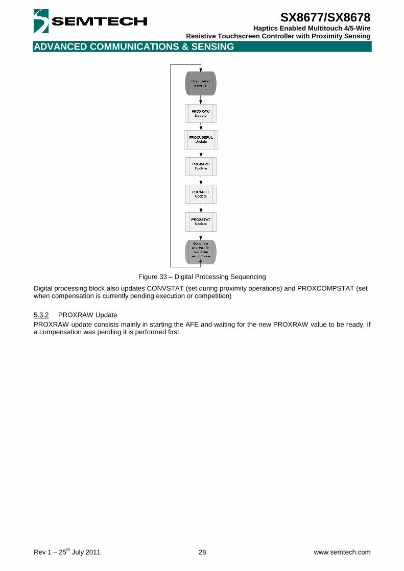
Figure 33 – Digital Processing Sequencing
Digital processing block also updates CONVSTAT (set during proximity operations) and PROXCOMPSTAT (set when compensation is currently pending execution or competition)
5.3.2 PROXRAW Update PROXRAW update consists mainly in starting the AFE and waiting for the new PROXRAW value to be ready. If a compensation was pending it is performed first.

ADVANCED COMMUNICATIONS & SENSING
Rev 1 – 25th July 2011 29 www.semtech.com
SX8677/SX8678 Haptics Enabled Multitouch 4/5-Wire
Resistive Touchscreen Controller with Proximity Sensing
Figure 34 – ProxRaw Update
5.3.3 PROXUSEFUL Update PROXUSEFUL update consists in filtering PROXRAW upfront to remove its potential high frequencies components(system noise, interferer, etc) and extract only user activity (few Hz max) and slow environment changes.
Figure 35 – PROXUSEFUL Update
F(PROXRAW ; PROXUSEFUL[n-1] ; PROXRAWFILT) = (1 - PROXRAWFILT).PROXRAW + PROXRAWFILT.PROXUSEFUL[n-1]

ADVANCED COMMUNICATIONS & SENSING
Rev 1 – 25th July 2011 30 www.semtech.com
SX8677/SX8678 Haptics Enabled Multitouch 4/5-Wire
Resistive Touchscreen Controller with Proximity Sensing
5.3.4 PROXAVG Update PROXAVG update consists in averaging PROXUSEFUL to ignore its “fast” variations (i.e. user finger/palm/hand) and extract only the very slow variations of environment capacitance CEnv. One can program positive and negative debounced thresholds (PROXAVGPOSTHRESH/PROXAVGPOSDEB and PROXAVGNEGTHRESH/PROXAVGNEGDEB) within which PROXAVG can vary without triggering compensation (ie small acceptable environment drift). Large positive values of PROXUSEFUL are considered as normal (user finger/hand/head) but large negative values are considered abnormal and should be compensated quickly. For this purpose, the averaging filter coefficient can be set independently for positive and negative variations via PROXAVGPOSFILT and PROXAVGNEGFILT. Typically we have PROXAVGPOSFILT > PROXAVGNEGFILT to filter out (abnormal) negative events faster. To prevent PROXAVG to be “corrupted” by user activity (should only reflect environmental changes) it is freezes when proximity is detected.
Figure 36 – ProxAvg vs Proximity Event

ADVANCED COMMUNICATIONS & SENSING
Rev 1 – 25th July 2011 31 www.semtech.com
SX8677/SX8678 Haptics Enabled Multitouch 4/5-Wire
Resistive Touchscreen Controller with Proximity Sensing
Figure 37 – ProxAvg Update
F(PROXUSEFUL ; PROXAVG[n-1] ; PROXAVGxxxFILT) = (1 - PROXAVGxxxFILT).PROXUSEFUL + PROXAVGxxxFILT.PROXAVG[n-1]
xxx = POS or NEG

ADVANCED COMMUNICATIONS & SENSING
Rev 1 – 25th July 2011 32 www.semtech.com
SX8677/SX8678 Haptics Enabled Multitouch 4/5-Wire
Resistive Touchscreen Controller with Proximity Sensing
5.3.5 PROXDIFF Update PROXDIFF update consists in the complementary operation i.e. subtracting PROXAVG to PROXUSEFUL to ignore slow capacitances variations (CEnv) and extract only the user related variations i.e. CUser.
Figure 38 – ProxDiff Update
5.3.6 PROXSTAT Update PROXSTAT update consists in taking PROXDIFF information (CUser), comparing it with a user programmable threshold PROXTHRESH and finally updating PROXSTAT accordingly. When PROXSTAT=1, PROXAVG is frozen to prevent the user proximity signal averaging and hence absorbed into CEnv.
Figure 39 – PROXSTAT Update

ADVANCED COMMUNICATIONS & SENSING
Rev 1 – 25th July 2011 33 www.semtech.com
SX8677/SX8678 Haptics Enabled Multitouch 4/5-Wire
Resistive Touchscreen Controller with Proximity Sensing
5.4 Host Operation
5.4.1 General Description If PROXIRQSEL = 0, an interrupt can be triggered when the user is detected to be close, detected to be far, or both (PROXCLOSEIRQEN, PROXFARIRQEN).
Figure 40 – Proximity Sensing Host Operation (Pen Trigger Mode ; RegIrqMsk[6:4] = 110 ; PROXIRQSEL = 0)
If PROXIRQSEL = 1, instead of the proximity “Far” state, an interrupt can be triggered at the end of each proximity sensing operation indicating to the host when the proximity sensing block is running (PROXCONVDONEIRQEN). This may be used by the host to synchronize noisy system operations or to read PROXRAW, PROXUSEFUL, PROXAVG, PROXDIFF synchronously for monitoring purposes.
Figure 41 – Proximity Sensing Host Operation (Pen Trigger Mode ; RegIrqMsk[6:4] = 010 ; PROXIRQSEL = 1)
In both cases above, an interrupt can also be triggered at the end of compensation (PROXCOMPDONEEN).
5.4.2 Proximity Sensing vs Touch Operations As previously mentioned, touch and proximity operations share the same ADC and hence the chip implements time multiplexing between these two types of operations. Also, proximity sensing doesn’t need to be performed while pen is down (not needed as host knows already something touches the screen). In all operating modes, if PROXSCANPERIOD = 0, no proximity operation is performed (i.e. § 4.7). The following hence assumes PROXSCANPERIOD != 0. For simplicity we also assume that NIRQ is only used for reporting touch operations i.e. RegIrqMsk[6:4] = 000 (PROXSTAT mapped to AUX pin, or polled via I2C). In MAN mode, a CONVERT command (if not preceded by a SELECT command) will perform a proximity sensing operation before the touchscreen operation, whatever the pen status. Hence please note that if the
Pen Detection
NIRQ
I2C Read RegIrqSrc
Proximity Sensing (Analog + Digital)
PROXSTAT
CONVSTAT
PROXSCANPERIOD tick
User in range User out of range
Pen Detection
NIRQ
I2C Read RegIrqSrc
Proximity Sensing (Analog + Digital)
PROXSTAT
CONVSTAT
PROXSCANPERIOD tick
User in range User out of range

ADVANCED COMMUNICATIONS & SENSING
Rev 1 – 25th July 2011 34 www.semtech.com
SX8677/SX8678 Haptics Enabled Multitouch 4/5-Wire
Resistive Touchscreen Controller with Proximity Sensing
touchscreen is used as the proximity sensor and is being touched when the conversion is performed, the proximity measurement result may be incorrect.
Figure 42 – Manual Mode – CONVERT Command (CHAN = Y ; PROXSCANPERIOD != 0; Pen down)
If the screen is not touched, only the proximity sensing operation is performed.
Figure 43 – Manual Mode – CONVERT Command (CHAN = Y ; PROXSCANPERIOD != 0, Pen up)
In PENDET and PENTRG mode, a proximity sensing operation will be performed regularly as defined in PROXSCANPERIOD, but only if pen is not detected.
Figure 44 – Pen Detect Mode (RegIrqMsk[6:2] = 00011 ; PROXSCANPERIOD = 001 ie 1/TOUCHRATE)
I2C
Channel Bias
CONVERT Y
Channel Conv e rsion
READ CHANNEL
PROX
NIRQ (RegIrqMsk[6:3]=0001)
CONVSTAT
Idle Touch Conversion
Pen Detection
NIRQ
Pen Touch Pen Release
I2C Read RegIrqSrc
Proximity Sensing
CONVSTAT
PENSTAT
TOUCHRATE tick
I2C
Channel Bias
CONVERT Y
Channel Conv e rsion
READ CHANNEL
POWDLY
Y
Y
PROX
NIRQ (RegIrqMsk[6:3]=0001)
CONVSTAT

ADVANCED COMMUNICATIONS & SENSING
Rev 1 – 25th July 2011 35 www.semtech.com
SX8677/SX8678 Haptics Enabled Multitouch 4/5-Wire
Resistive Touchscreen Controller with Proximity Sensing
Figure 45 – Pen Trigger Mode (RegIrqMsk[6:2] = 00010 ; PROXSCANPERIOD = 001 ie 1/TOUCHRATE)
5.4.3 Minimum Scan Period (i.e. PROXSCANPERIOD) Similarly to touch operations (Cf. § 4.7.5), if PROXSCANPERIOD is too short for proximity sensing operations to be completed, the rate tick(s) affected are ignored until operations are completed and the following tick is taken into account for the next planned operation. Please note that compensation lasts about ~16 times longer than a normal proximity sensing operation.
Idle Touch Conversion
Pen Detection
NIRQ
TOUCHRATE tick
Pen Touch Pen Release
I2C Read Channel
Proximity Sensing
PENSTAT
CONVSTAT

ADVANCED COMMUNICATIONS & SENSING
Rev 1 – 25th July 2011 36 www.semtech.com
SX8677/SX8678 Haptics Enabled Multitouch 4/5-Wire
Resistive Touchscreen Controller with Proximity Sensing
6 HAPTICS INTERFACE (SX8677/78)
6.1 Introduction Haptics technology is commonly used in systems which include a touchscreen interface. Its purpose is to provide tactile feedback to the user to acknowledge a touch event hence improving greatly the robustness of the system and user comfort and perception. The on-chip haptics interface is designed to drive two common actuator types: Eccentric Rotating Mass (ERM) and Linear Resonant Actuator (LRA). This is performed without any external component due to fully embedded analog processing and with very limited host interaction due to the embedded digital processing block.
Figure 46 – Haptics Interface Overview
The host configures drive parameters from the I2C port according to the particular haptics load to be used. The haptics drive level is then controlled in real time by either of two methods: by a dedicated digital pin, MIN, which accepts a pulse-width-modulated (PWM) digital signal; or by writing the desired output level directly to a register via the I2C interface. This digital information is filtered to prevent fast transitions and hence high current spikes (HAPTBW), converted into the analog domain by an 8-bit DAC, and finally amplified (HAPTGAIN) to provide a differential signal between MOUTP and MOUTN pins which can be directly connected to the motor thanks to their high drive current capability. For better isolation from the rest of the chip, the haptics interface analog block has its own power supply pins MVDD and MGND. The haptics interface is enabled when HAPTTYPEEN != 0.
6.2 ERM Load
6.2.1 Introduction An ERM is a DC motor with an off-balance load to create a vibration. Speed and direction are controlled by the applied voltage. The ERM load is selected when HAPTTYPEEN = 10.

ADVANCED COMMUNICATIONS & SENSING
Rev 1 – 25th July 2011 37 www.semtech.com
SX8677/SX8678 Haptics Enabled Multitouch 4/5-Wire
Resistive Touchscreen Controller with Proximity Sensing
Accelerating
Figure 47 – ERM Drive Signal Example
If AmplitudeCode is within HAPTSQUELCH range (for more than 512/MIN_Freq in PWM mode, for more than 512/FOSCL in I2C mode):
VMOUT = 0V Else:
VMOUT(V) = (AmplitudeCode / 127) x 1.135 * HAPTGAIN AmplitudeCode (signed) is defined differently depending on the mode selected (PWM or I2C), see below. Please note that whatever setting, VMOUT is physically limited to [MVDD;-MVDD], i.e. saturation effect.
6.2.2 PWM Mode PWM mode is selected when HAPTMODE = 0. In this mode, AmplitudeCode is extracted/updated at each MIN period from MIN_DutyCycle:
• MIN_DutyCycle ≈ 0% => AmplitudeCode = -127 • … • MIN_DutyCycle = 49.6% => AmplitudeCode = -1 • MIN_DutyCycle = 50% => AmplitudeCode = 0 • MIN_DutyCycle = 50.4% => AmplitudeCode = +1 • … • MIN_DutyCycle ≈ 100% => AmplitudeCode = +127
6.2.3 I2C Mode I2C mode is selected when HAPTMODE = 1. In this mode, AmplitudeCode = HAPTAMP (signed, internally sampled at FOSCL). MIN is not used and should be grounded. HAPTRANGE must be set to 1.
6.3 LRA Load
6.3.1 Introduction An LRA is a spring and mass with an electro-magnetic coil to move the mass. It is operated by applying an AC signal at its resonant frequency (typ. ~175 Hz). Like pushing a swing at its resonance, it doesn’t need much energy to keep it going, so drive current requirements are much lower than for ERMs. LRAs have moderately high Q factors so that the drive frequency must match the resonant frequency within a few Hz to get optimum amplitude. LRA load is selected when HAPTTYPEEN = 01.

ADVANCED COMMUNICATIONS & SENSING
Rev 1 – 25th July 2011 38 www.semtech.com
SX8677/SX8678 Haptics Enabled Multitouch 4/5-Wire
Resistive Touchscreen Controller with Proximity Sensing
Figure 48 – LRA Drive Signal Example
The carrier frequency of VMOUT_Freq is defined as following:
VMOUT_Freq(Hz) = (MIN_Freq / HAPTRANGE) (PWM mode)
OR
VMOUT_Freq(Hz) = (MIN_Freq / HAPTRANGE) / (HAPTTIMER +1) (I2C mode) If AmplitudeCode is within HAPTSQUELCH range (for more than 512/VMOUT_Freq):
VMOUT_Envelope = 0V Else:
VMOUT_Envelope(V) = (AmplitudeCode / 127) x 1.135 * HAPTGAIN
AmplitudeCode (signed) is defined differently depending on the mode selected (PWM or I2C), see below. Please note that whatever setting, VMOUT is physically limited to [MVDD;-MVDD], ie saturation effect.
6.3.2 PWM Mode PWM mode is selected when HAPTMODE = 0. In this mode, AmplitudeCode is extracted/updated at each MIN period from MIN_DutyCycle:
• MIN_DutyCycle ≈ 0% => AmplitudeCode = -127 • … • MIN_DutyCycle = 49.6% => AmplitudeCode = -1 • MIN_DutyCycle = 50% => AmplitudeCode = 0 • MIN_DutyCycle = 50.4% => AmplitudeCode = +1 • … • MIN_DutyCycle ≈ 100% => AmplitudeCode = +127
6.3.3 I2C Mode I2C mode is selected when HAPTMODE = 1. In this mode, AmplitudeCode = HAPTAMP (signed, internally sampled at MIN_Freq). MIN is still used to extract VMOUT carrier frequency.
6.4 Short-Circuit Protection The haptics interface integrates a short-circuit protection circuit which detects when MIDD is abnormally high i.e. above ISHORT. Under a short-circuit event (HAPTSHORTSTAT=1) the haptics block will stop operation (MOUTN & MOUTP grounded). When the short-circuit is removed the haptics operations will resume normally.
ADVANCED COMMUNICATIONS & SENSING
Rev 1 – 25th July 2011 39 www.semtech.com
SX8677/SX8678 Haptics Enabled Multitouch 4/5-Wire
Resistive Touchscreen Controller with Proximity Sensing
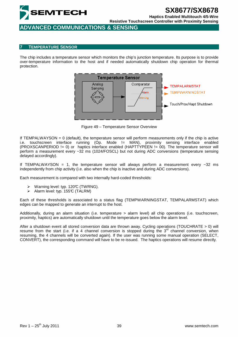
7 TEMPERATURE SENSOR The chip includes a temperature sensor which monitors the chip’s junction temperature. Its purpose is to provide over-temperature information to the host and if needed automatically shutdown chip operation for thermal protection.
Figure 49 – Temperature Sensor Overview
If TEMPALWAYSON = 0 (default), the temperature sensor will perform measurements only if the chip is active i.e. touchscreen interface running (Op. Mode != MAN), proximity sensing interface enabled (PROXSCANPERIOD != 0) or haptics interface enabled (HAPTTYPEEN != 00). The temperature sensor will perform a measurement every ~32 ms (1024/FOSCL) but not during ADC conversions (temperature sensing delayed accordingly). If TEMPALWAYSON = 1, the temperature sensor will always perform a measurement every ~32 ms independently from chip activity (i.e. also when the chip is inactive and during ADC conversions). Each measurement is compared with two internally hard-coded thresholds:
Warning level: typ. 120°C (TWRNG). Alarm level: typ. 155°C (TALRM)
Each of these thresholds is associated to a status flag (TEMPWARNINGSTAT, TEMPALARMSTAT) which edges can be mapped to generate an interrupt to the host. Additionally, during an alarm situation (i.e. temperature > alarm level) all chip operations (i.e. touchscreen, proximity, haptics) are automatically shutdown until the temperature goes below the alarm level. After a shutdown event all stored conversion data are thrown away. Cycling operations (TOUCHRATE > 0) will resume from the start (i.e. if a 4 channel conversion is stopped during the 3rd channel conversion, when resuming, the 4 channels will be converted again). If the user was running some manual operation (SELECT, CONVERT), the corresponding command will have to be re-issued. The haptics operations will resume directly.

ADVANCED COMMUNICATIONS & SENSING
Rev 1 – 25th July 2011 40 www.semtech.com
SX8677/SX8678 Haptics Enabled Multitouch 4/5-Wire
Resistive Touchscreen Controller with Proximity Sensing
8 INTERRUPT (NIRQ)
8.1 Introduction The purpose of the NIRQ pin is to indicate to the host (via a falling edge) when any of the events considered being time-critical has occurred. Non time-critical events can be monitored via I2C by reading regularly the relevant status bits.
8.2 Registers Overview
8.2.1 RegIrqMsk This register allows the host to decide which interrupt sources he wants to monitor via the NIRQ signal. Please note that a reset event will always trigger NIRQ falling edge whatever RegIrqMsk (Cf § 10)
8.2.2 RegIrqSrc This register indicates to the host which of the interrupt sources triggered the NIRQ signal. More than one bit can be set if several events occurred before host reads the register. If bit 3 is OFF, reading the register will clear it together with releasing NIRQ signal. Else, if bit 3 is ON and we are in MAN or PENTRG mode, both register and NIRQ will be cleared only once all channel data have been read. All ADC related operations (touch conversion, proximity conversion, pen detection) are stopped as long as all channel data have not been read. Bits which RegIrqMsk corresponding bits are set to 0 (ie source not monitored) will always read 0 even if the event actually occurred.
8.2.3 RegStat This register regroups all status information of the chip and is used by all interrupt sources to detect the relevant events. For each bit, if the relevant block is ON its value is constantly updated, else it is set to 0. This register update is completely independent from RegIrqMsk.
8.3 Host Procedure - Configure the different blocks parameters(TS, Proximity, etc) - Program RegIrqMsk to start monitoring what is considered to be “time-critical” events - Enable the blocks to start RegStat update and hence NIRQ process. - Each time NIRQ falling edge occurs, read RegIrqSrc to know which “time-critical” event occurred (+ read
channel data if relevant) - In addition, RegStat can be read anytime to get the whole picture including also what is considered to be
“non time-critical” information.

ADVANCED COMMUNICATIONS & SENSING
Rev 1 – 25th July 2011 41 www.semtech.com
SX8677/SX8678 Haptics Enabled Multitouch 4/5-Wire
Resistive Touchscreen Controller with Proximity Sensing
9 AUXILIARY PINS (AUX1/AUX2/AUX3) The chip has three auxiliary pins which can be used:
1. By the touchscreen interface when using a 5-wire touchscreen (WIPER=AUX1) 2. By the proximity sensing interface (PROXSENSORCON and PROXSHIELDCON) to use an external
sensor and/or shield instead of the touchscreen’s plates
3. By the host (RegAux0-1) to monitor any RegStat and/or RegIrqSrc bits in real time without having to use NIRQ or perform I2C polling.
ADVANCED COMMUNICATIONS & SENSING
Rev 1 – 25th July 2011 42 www.semtech.com
SX8677/SX8678 Haptics Enabled Multitouch 4/5-Wire
Resistive Touchscreen Controller with Proximity Sensing
10 RESET
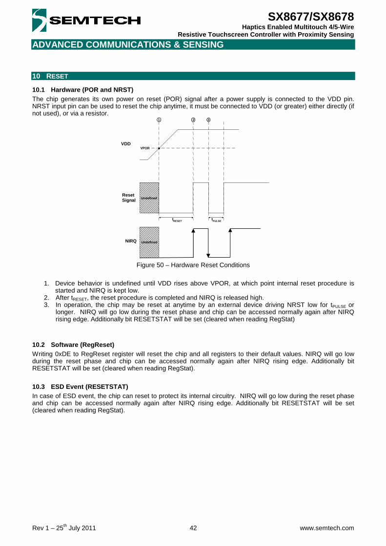
10.1 Hardware (POR and NRST) The chip generates its own power on reset (POR) signal after a power supply is connected to the VDD pin. NRST input pin can be used to reset the chip anytime, it must be connected to VDD (or greater) either directly (if not used), or via a resistor.
Figure 50 – Hardware Reset Conditions
1. Device behavior is undefined until VDD rises above VPOR, at which point internal reset procedure is
started and NIRQ is kept low. 2. After tRESET, the reset procedure is completed and NIRQ is released high. 3. In operation, the chip may be reset at anytime by an external device driving NRST low for tPULSE or
longer. NIRQ will go low during the reset phase and chip can be accessed normally again after NIRQ rising edge. Additionally bit RESETSTAT will be set (cleared when reading RegStat)
10.2 Software (RegReset) Writing 0xDE to RegReset register will reset the chip and all registers to their default values. NIRQ will go low during the reset phase and chip can be accessed normally again after NIRQ rising edge. Additionally bit RESETSTAT will be set (cleared when reading RegStat).
10.3 ESD Event (RESETSTAT) In case of ESD event, the chip can reset to protect its internal circuitry. NIRQ will go low during the reset phase and chip can be accessed normally again after NIRQ rising edge. Additionally bit RESETSTAT will be set (cleared when reading RegStat).
Undefined
t RESET
Reset Signal
VDD VPOR
t PULSE
1 2 3
NIRQ Undefined

ADVANCED COMMUNICATIONS & SENSING
Rev 1 – 25th July 2011 43 www.semtech.com
SX8677/SX8678 Haptics Enabled Multitouch 4/5-Wire
Resistive Touchscreen Controller with Proximity Sensing
11 I2C INTERFACE
11.1 Introduction The chip is a read-write slave-mode I2C device and complies with the Philips I2C standard Version 2.1 dated January, 2000. The chip has a few user-accessible internal 8-bits registers to set the various parameters of operation (Cf. § 12 for detailed configuration registers description). The I2C interface has been designed for program flexibility, in that once the slave address has been sent to the chip enabling it to be a slave transmitter/receiver, any register can be written or read independently of each other. The start and stop commands frame the data-packet and the repeat start condition is allowed if necessary. 2 lines are used to exchange data between an external master host and the slave device:
• SCL : Serial CLock • SDA : Serial DAta
Seven bit addressing is used and ten bit addressing is not allowed. Any general call address will be ignored by the chip. The chip is not CBUS compatible and can operate in standard mode (100kbit/s) or fast mode (400kbit/s).
11.2 I2C Address On the QFN package an ADDR pin is made available to select between the two pre-programmed I2C addresses of the device. On the CSP package ADDR is internally connected to ground. This is illustrated in table below.
Package ADDR Address Description 0 0x48 (1001000) First I2C address
QFN 1 0x49 (1001001) Second I2C address
CSP 0 0x48 (1001000) First (and unique) I2C address Table 9 – I2C Address
Please note that upon request, a custom I2C Address can be pre-programmed by Semtech.
11.3 Write Register The I2C write register sequence is given in figure below. After the start condition [S], the chip slave address (SA) is sent, followed by an eighth bit (W=‘0’) indicating a write. The chip then acknowledges [A] that it is being addressed, and the host sends a CR byte consisting in ‘00’ followed by the chip register address (RA). The chip acknowledges [A] and the host sends the appropriate data byte (WD0) to be written. Again the chip acknowledges [A]. In case the host needs to write more data, a succeeding data byte will follow (WD1), acknowledged by the slave [A]. This sequence will be repeated until the host terminates the transfer with the stop condition [P].
Figure 51 – I2C Write Register
The register address increments automatically when successive data bytes (WD1...WDn) are supplied by the host.

ADVANCED COMMUNICATIONS & SENSING
Rev 1 – 25th July 2011 44 www.semtech.com
SX8677/SX8678 Haptics Enabled Multitouch 4/5-Wire
Resistive Touchscreen Controller with Proximity Sensing
The correct sampling of the screen by the chip and the host I2C bus traffic are events that might occur simultaneously. The chip will synchronize these events by the use of clock stretching if that is required. The stretching occurs directly after the last received command bit (see figure above).
11.4 Read Register The I2C read register sequence is given in figure below. After the start condition [S], the chip slave address (SA) is sent, followed by an eighth bit (W=‘0’) indicating a write. The chip then acknowledges [A] that it is being addressed, and the host responds with a CR byte consisting in ‘01’ followed by the register address (RA). The chip acknowledges [A] and the host sends the repeated start Condition [Sr]. Once again, the chip slave address (SA) is sent, followed by an eighth bit (R=‘1’) indicating a read. The chip responds with an acknowledge [A] and the data byte (RD0). If the host needs to read more data it will acknowledge [A] and the chip will send the next data byte (RD1). This sequence will be repeated until the host terminates the transfer with a NACK [N] followed by a stop condition [P].
Figure 52 – I2C Read Register
The register address increments automatically when successive data bytes (RD1...RDn) are read by the host. The correct sampling of the screen by the chip and the host I2C bus traffic are events that might occur simultaneously. The chip will synchronize these events by the use of clock stretching if that is required. The stretching occurs directly after the last received command bit (see figure above).
11.5 Write Command (Touchscreen Interface) The I2C write command sequence is given in figure below. After the start condition [S], the chip slave address (SA) is sent, followed by an eighth bit (W=‘0’) indicating a write. The chip then acknowledges [A] that it is being addressed, and the host responds with a CR byte consisting in Command(7:0) (see table below). The chip acknowledges [A] and the host sends a stop [P].
Figure 53 – I2C Write Command
The sampling of the screen by the chip and the host I2C bus traffic are events that might occur simultaneously. The chip will synchronize these events by the use of clock stretching if that is required. The stretching occurs directly after the last received command bit (see figure above).

ADVANCED COMMUNICATIONS & SENSING
Rev 1 – 25th July 2011 45 www.semtech.com
SX8677/SX8678 Haptics Enabled Multitouch 4/5-Wire
Resistive Touchscreen Controller with Proximity Sensing
Command Command(7:0) Function SELECT 1 0 1 0 X Chan(2:0) Select and bias channel. CONVERT 1 0 1 1 X Chan(2:0) Convert channel. MAN 1 1 0 0 X X X X Enter manual mode. PENDET 1 1 0 1 X X X X Enter pen detect mode. PENTRG 1 1 1 0 X X X X Enter pen trigger mode.
Table 10 : Command Codes
Channel Chan(2:0) Description X 0 0 0 X channel Y 0 0 1 Y channel Z1 0 1 0 First channel for pressure measurement Z2 0 1 1 Second channel for pressure measurement RX 1 0 1 X multitouch measurement RY 1 1 0 Y multitouch measurement SEQ 1 1 1 Channels enabled in RegChanMsk register
Table 11 : Channel Codes
11.6 Read Channel (Touchscreen Interface) The I2C read channel sequence is given in figure below. After the start condition [S], the chip slave address (SA) is sent, followed by an eighth bit (R=‘1’) indicating a read. The chip responds with an acknowledge [A] and the first data byte (RD0). The host sends an acknowledge [A] and the chip responds with the second data byte (RD1). If the host needs to read more channels, it will acknowledge [A] and the chip will send the next data bytes. This sequence will be repeated until the host terminates with a NACK [N] followed immediately by a stop [P]. The channel data that can be read is defined by RegChanMsk, or the last convert command in manual mode. A maximum number of 12 data bytes can be read when all channels (X, Y, Z1, Z2, RX, RY) are activated in RegChanMsk. The STOP [P] (if following the last valid data) releases high the NIRQ line. All ADC related operations (touch conversion, proximity conversion, pen detection) are stopped as long as all valid channel data have not been read (ie as long as NIRQ is low).
Figure 54 – I2C Read Channel
The sampling of the screen by the chip and the host I2C bus traffic are events that might occur simultaneously. The chip will synchronize these events by the use of clock stretching if that is required. The stretching occurs directly after the address and read bit have been sent for the I2C read channels command (see figure above). The channel data is sent with the following order: X, Y, Z1, Z2, RX, RY. It is coded as described in figure below Typical applications require only X and Y coordinates, thus only 4 bytes of data will be read in this case.

ADVANCED COMMUNICATIONS & SENSING
Rev 1 – 25th July 2011 46 www.semtech.com
SX8677/SX8678 Haptics Enabled Multitouch 4/5-Wire
Resistive Touchscreen Controller with Proximity Sensing
CHAN(2:0)
RD0
D(11:8) D(7:0)
RD1
0
Figure 55 – Channel Data Format
The 3 bits CHAN(2:0) are defined in the previous table and show which channel data is referenced. The channel data D(11:0) is of unsigned format and corresponds to a value between 0 and 4095. The chip will return 0xFFFF in case of invalid data; this occurs when:
• host tries to read channels which have not been converted. For example if the chip converts X and Y and the host tries to read X, Y, Z1 and Z2.
• a conversion has been done while the screen wasn’t touched , i.e. pen up (not detected).

ADVANCED COMMUNICATIONS & SENSING
Rev 1 – 25th July 2011 47 www.semtech.com
SX8677/SX8678 Haptics Enabled Multitouch 4/5-Wire
Resistive Touchscreen Controller with Proximity Sensing
12 REGISTERS DETAILED DESCRIPTION Address Name Default Description
0x00 RegTouch0 0x00 0x01 RegTouch1 0x20 0x02 RegTouch2 0x00 0x03 RegTouch3 0x00 0x04 RegChanMsk 0xC0
Touchscreen Interface
0x05 RegHapt0 0x00 0x06 RegHapt1 0x00 0x07 RegHapt2 0x00 0x08 RegHapt3 0x80 0x09 RegHapt4 0x00 0x0A RegHapt5 0x00
Haptics Interface and Temperature Sensor
0x0B RegProx0 0x00 0x0C RegProx1 0x00 0x0D RegProx2 0x00 0x0E RegProx3 0x00 0x0F RegProx4 0x00 0x10 RegProx5 0x00 0x11 RegProx6 0x00 0x12 RegProx7 0x00 0x13 RegProx8 0x00 0x14 RegProx9 0x00 0x15 RegProx10 0x00 0x16 RegProx11 0x00 0x17 RegProx12 0x00 0x18 RegProx13 0x00 0x19 RegProx14 0x00 0x1A RegProx15 0x00 0x1B RegProx16 0x00 0x1C RegProx17 0x00 0x1D RegProx18 0x00 0x1E RegProx19 0x00 0x1F RegProx20 0x00 0x20 RegProx21 0x01 0x21 RegProx22 0x00
Proximity Sensing Interface
0x22 RegIrqMsk 0x08 0x23 RegIrqSrc 0x00 0x24 RegStat 0x00
Interrupt and Chip Status
0x25 RegAux0 0x00 0x26 RegAux1 0x00
Auxiliary Functions
0x3F RegReset 0x00 Software Reset Table 12 : Registers Overview
NOTES: 1) Addresses not listed above are reserved and should not be written. 2) Reserved bits should be left to their default value unless otherwise specified. 3) Proximity related registers/bits do not apply to SX8678.

ADVANCED COMMUNICATIONS & SENSING
Rev 1 – 25th July 2011 48 www.semtech.com
SX8677/SX8678 Haptics Enabled Multitouch 4/5-Wire
Resistive Touchscreen Controller with Proximity Sensing
Bits Variable Default Description 7:4 TOUCHRATE 0000 Defines the touch coordinates acquisition rate:
0000 : OFF. 0001 : 10 cps 0010 : 20 cps 0011 : 40 cps 0100 : 60 cps 0101 : 80 cps 0110 : 100 cps 0111 : 200 cps 1000 : 300 cps 1001 : 400 cps 1010 : 500 cps 1011 : 1 kcps 1100 : 2 kcps 1101 : 3 kcps 1110 : 4 kcps 1111 : 5 kcps Values above assume typical FOSCL, else vary accordingly.
3:0 POWDLY 0000 Defines the bias settling time for each channel’s first conversion: 0000 : 0.5 us 0001 : 1.1 us 0010 : 2.2 us 0011 : 4.4 us 0100 : 8.9 us 0101 : 17.8 us 0110 : 35.5 us 0111 : 71.0 us 1000 : 142 us 1001 : 284 us 1010 : 768 us 1011 : 1.14 ms 1100 : 2.27 ms 1101 : 4.75 ms 1110 : 9.09 ms 1111 : 18.19 ms Values above assume typical FOSCH, else vary accordingly.
Table 13 : RegTouch0 (Addr 0x00)
Bits Variable Default Description 7:5 Reserved 001 4 TSTYPE 0 Defines the type of touchscreen:
0 : 4-wire 1 : 5-wire
3:2 RPNDT 00 Defines the pen detection circuit’s pull-up resistor value: 00 : 114 kOhms 01 : 228 kOhms 10 : 57 kOhms 11 : 28 kOhms
1:0 FILT 00 Defines the channel filtering algorithm: 00 : OFF (Nfilt = 1) 01 : 3 sample averaging (Nfilt = 3) 10 : 5 sample averaging (Nfilt = 5) 11 : 3 sample averaging after removal of extreme values (Nfilt = 7)
Table 14 : RegTouch1 (Addr 0x01)

ADVANCED COMMUNICATIONS & SENSING
Rev 1 – 25th July 2011 49 www.semtech.com
SX8677/SX8678 Haptics Enabled Multitouch 4/5-Wire
Resistive Touchscreen Controller with Proximity Sensing
Bits Variable Default Description 7:4 Reserved 0000 3:0 SETDLY 0000 Defines the bias settling time for each channel’s subsequent conversion
(i.e. when filtering is enabled): 0000 : 0.5 us 0001 : 1.1 us 0010 : 2.2 us 0011 : 4.4 us 0100 : 8.9 us 0101 : 17.8 us 0110 : 35.5 us 0111 : 71.0 us 1000 : 142 us 1001 : 284 us 1010 : 768 us 1011 : 1.14 ms 1100 : 2.27 ms 1101 : 4.75 ms 1110 : 9.09 ms 1111 : 18.19 ms Values above assume typical FOSCH, else vary accordingly.
Table 15 : RegTouch2 (Addr 0x02)
Bits Variable Default Description 7:6 Reserved 00 5:3 RMSELY 000 Cf. § 4.5 2:0 RMSELX 000 Cf. § 4.5
Table 16 : RegTouch3 (Addr 0x03)
Bits Variable Default Description
7 XCONV 1 Enables X channel conversion: 0 : OFF 1 : ON
6 YCONV 1 Enables Y channel conversion: 0 : OFF 1 : ON
5 Z1CONV 0 Enables Z1 channel conversion: 0 : OFF 1 : ON
4 Z2CONV 0 Enables Z2 channel conversion: 0 : OFF 1 : ON
3 Reserved 0 2 RXCONV 0 Enables RX channel conversion:
0 : OFF 1 : ON
1 RYCONV 0 Enables RY channel conversion: 0 : OFF 1 : ON
0 Reserved 0 Table 17 : RegChanMsk (Addr 0x04)
Bits Variable Default Description
7 HAPTMODE 0 Defines the haptics mode/input: 0 : PWM 1 : I2C

ADVANCED COMMUNICATIONS & SENSING
Rev 1 – 25th July 2011 50 www.semtech.com
SX8677/SX8678 Haptics Enabled Multitouch 4/5-Wire
Resistive Touchscreen Controller with Proximity Sensing
6:5 HAPTTYPEEN 00 Defines the haptics load: 00 : OFF. Haptics block disabled. 01 : LRA 10 : ERM 11 : Reserved
4 HAPTRANGE 0 Defines MIN prescaler value: 0 : 128 1 : 256
3:0 HAPTGAIN 0000 Defines the haptics output gain: 0000 : 1 0001 : ~1.17 0010 : ~1.34 0011 : ~1.51 0100 : ~1.67 0101 : ~1.84 0110 : ~2.01 0111 : ~2.18 1000 : ~2.35 1001 : ~2.52 1010 : ~2.69 1011 : ~2.86 1100 : ~3.03 1101 : ~3.20 1110 : ~3.37 1111 : ~3.53 Exact formula is 1 + Code * 0.169
Table 18 : RegHapt0 (Addr 0x05)
Bits Variable Default Description 7:6 Reserved 00 5:3 HAPTSQUELCH 000 Defines the Haptics squelch, i.e. the range of AmplitudeCode
(HAPTAMP or MIN duty cycle equivalent, Cf. § 6) which will generate a 0V output (VMOUT): 000 : OFF. No squelch. 001 : -1 < AmplitudeCode < +1 (ie. AmplitudeCode = 0) 010 : -2 < AmplitudeCode < +2 011 : -4 < AmplitudeCode < +4 100 : -8 < AmplitudeCode < +8 101 : -16 < AmplitudeCode < +16 110 : -32 < AmplitudeCode < +32 111 : -64 < AmplitudeCode < +64
2 TEMPWRNIRQEDG 0 Enables TempWrnIrq to be generated when the chip temperature gets below the alarm threshold : 0 : OFF. TempWrnIrq generated only when the chip temperature gets above the alarm threshold. 1 : ON. TempWrnIrq generated both when the chip temperature gets above and below the alarm threshold.
1 TEMPALRMIRQEDG 0 Enables TempAlrmIrq to be generated when the chip temperature gets below the alarm threshold : 0 : OFF. TempAlrmIrq generated only when the chip temperature gets above the alarm threshold. 1 : ON. TempAlrmIrq generated both when the chip temperature gets above and below the alarm threshold.
0 TEMPALWAYSON 0 Enables the temperature monitoring even when no operation (touch, proximity, haptics) is enabled: 0 : OFF 1 : ON
Table 19 : RegHapt1 (Addr 0x06)

ADVANCED COMMUNICATIONS & SENSING
Rev 1 – 25th July 2011 51 www.semtech.com
SX8677/SX8678 Haptics Enabled Multitouch 4/5-Wire
Resistive Touchscreen Controller with Proximity Sensing
Bits Variable Default Description 7:0 HAPTAMP 0x00 Defines the haptics output polarity and level in I2C mode i.e.
AmplitudeCode (Cf. § 6) : 0xFF : +127 (Max positive) … 0x81 : +1 0x80 : +0 0x00 : -0 0x01 : -1 … 0x7F : -127 (Max negative) HAPTAMP[7] gives the sign of AmplitudeCode (1=>+;0=>-) while HAPTAMP[6:0] give its magnitude.
Table 20 : RegHapt2 (Addr 0x07)
Bits Variable Default Description 7:5 HAPTBW 100 Defines the haptics low-pass filter cut off frequency (Hz):
000 : OFF. No filtering. 001 : ~210 * SamplingFreq / 100 010 : ~280 * SamplingFreq / 100 011 : ~425 * SamplingFreq / 100 100 : ~565 * SamplingFreq / 100 101 : ~700 * SamplingFreq / 100 110 : ~850 * SamplingFreq / 100 111 : ~980 * SamplingFreq / 100 SamplingFreq is VMOUT_Freq in LRA mode and MIN_Freq (PWM) or FOSCL (I2C) in ERM mode (Cf. § 6)
4 HAPTHZ 0 Sets MOUTP and MOUTN to high impedance (HZ): 0 : Normal 1 : HZ
3 HAPTSHORTPROT 0 Disables short-circuit protection: 0 : ON . A short-circuit event will automatically stop haptics operation. 1 : OFF. A short-circuit event will not stop haptics operation. In both cases HAPTSHORTSTAT is still updated (and hence an interrupt can still be generated if needed)
2:0 HAPTTIMERMSB 000 Defines the haptics timer overflow value used to generate the LRA’s 128 or 256 multiple frequency from MIN.
Table 21 : RegHapt3 (Addr 0x08)
Bits Variable Default Description 7:0 HAPTTIMERLSB 0x00 Defines the haptics timer overflow value used to generate the LRA’s
128 or 256 multiple frequency from MIN. HAPTTIMER[9:0] values below 8 (ie 0-7) are reserved.
Table 22 : RegHapt4 (Addr 0x09)
Bits Variable Default Description 7:0 Reserved 0x00
Table 23 : RegHapt5 (Addr 0x0A)
Bits Variable Default Description
7 PROXRAWFILTSEL 0 Defines the proximity raw filtering range for PROXRAWFILT : 0 : Fast 1 : Slow
6 PROXIRQSEL 0 Defines the function of bits 5 of RegIrqMsk and RegIrqSrc. 0 : ProxFar 1 : ProxConvDone

ADVANCED COMMUNICATIONS & SENSING
Rev 1 – 25th July 2011 52 www.semtech.com
SX8677/SX8678 Haptics Enabled Multitouch 4/5-Wire
Resistive Touchscreen Controller with Proximity Sensing
5:4 PROXHYST 00 Defines the proximity detection hysteresis : 00 : OFF 01 : 32 10 : 128 11 : 512
3:0 PROXSCANPERIOD 0000 Defines the proximity scan period : 0000 : OFF. Proximity sensing disabled 0001 : 1 / TOUCHRATE (Cf. RegTouch0) 0010 : 2 / TOUCHRATE 0011 : 4 / TOUCHRATE 0100 : 8 / TOUCHRATE 0101 : 16 / TOUCHRATE 0110 : 32 / TOUCHRATE 0111 : 64 / TOUCHRATE 1000 : 128 / TOUCHRATE 1001 : 256 / TOUCHRATE 1010 : 512 / TOUCHRATE 1011 : 1024 / TOUCHRATE 1100 : 2048 / TOUCHRATE 1101 : 4096 / TOUCHRATE 1110 : 8192 / TOUCHRATE 1111 : 16384 / TOUCHRATE
Table 24 : RegProx0 (Addr 0x0B)
Bits Variable Default Description 7:0 PROXTHRESH 0x00 Defines the proximity detection threshold (for PROXSTAT update).
Threshold = 16 x register value Table 25 : RegProx1 (Addr 0x0C)
Bits Variable Default Description 7:6 PROXCLOSEDEB 00 Defines the “Close” debounce (for PROXSTAT update):
00 : OFF 01 : 2 samples 10 : 4 samples 11 : 8 samples
5:4 PROXFARDEB 00 Defines the “Far” debounce (for PROXSTAT update): 00 : OFF 01 : 2 samples 10 : 4 samples 11 : 8 samples
3:0 PROXCOMPPRD 0000 Defines the periodic compensation : 0 : OFF Else : register value x 128 samples
Table 26 : RegProx2 (Addr 0x0D)
Bits Variable Default Description 7:0 PROXSTUCK 0x00 Defines the stuck at timeout (ie max “Close” time before a
compensation is automatically requested) : 0 : OFF Else : register value x 16 samples
Table 27 : RegProx3 (Addr 0x0E)
Bits Variable Default Description 7:0 PROXAVGPOSTHRESH 0x00 Defines the average positive threshold (for compensation).
Threshold = 8 x register value Table 28 : RegProx4 (Addr 0x0F)
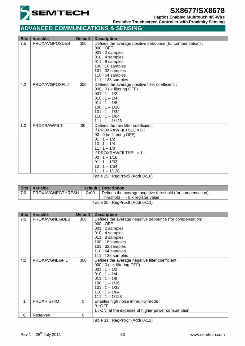
ADVANCED COMMUNICATIONS & SENSING
Rev 1 – 25th July 2011 53 www.semtech.com
SX8677/SX8678 Haptics Enabled Multitouch 4/5-Wire
Resistive Touchscreen Controller with Proximity Sensing
Bits Variable Default Description 7:5 PROXAVGPOSDEB 000 Defines the average positive debounce (for compensation) :
000 : OFF 001 : 2 samples 010 : 4 samples 011 : 8 samples 100 : 16 samples 101 : 32 samples 110 : 64 samples 111 : 128 samples
4:2 PROXAVGPOSFILT 000 Defines the average positive filter coefficient : 000 : 0 (ie filtering OFF) 001 : 1 – 1/2 010 : 1 – 1/4 011 : 1 – 1/8 100 : 1 – 1/16 101 : 1 – 1/32 110 : 1 – 1/64 111 : 1 – 1/128
1:0 PROXRAWFILT 00 Defines the raw filter coefficient. If PROXRAWFILTSEL = 0 : 00 : 0 (ie filtering OFF) 01 : 1 – 1/2 10 : 1 – 1/4 11 : 1 – 1/8 If PROXRAWFILTSEL = 1 : 00 : 1 – 1/16 01 : 1 – 1/32 10 : 1 – 1/64 11 : 1 – 1/128
Table 29 : RegProx5 (Addr 0x10)
Bits Variable Default Description 7:0 PROXAVGNEGTHRESH 0x00 Defines the average negative threshold (for compensation).
Threshold = – 8 x register value Table 30 : RegProx6 (Addr 0x11)
Bits Variable Default Description 7:5 PROXAVGNEGDEB 000 Defines the average negative debounce (for compensation) :
000 : OFF 001 : 2 samples 010 : 4 samples 011 : 8 samples 100 : 16 samples 101 : 32 samples 110 : 64 samples 111 : 128 samples
4:2 PROXAVGNEGFILT 000 Defines the average negative filter coefficient : 000 : 0 (i.e. filtering OFF) 001 : 1 – 1/2 010 : 1 – 1/4 011 : 1 – 1/8 100 : 1 – 1/16 101 : 1 – 1/32 110 : 1 – 1/64 111 : 1 – 1/128
1 PROXHIGHIM 0 Enables high noise immunity mode : 0 : OFF 1 : ON, at the expense of higher power consumption.
0 Reserved 0 Table 31 : RegProx7 (Addr 0x12)

ADVANCED COMMUNICATIONS & SENSING
Rev 1 – 25th July 2011 54 www.semtech.com
SX8677/SX8678 Haptics Enabled Multitouch 4/5-Wire
Resistive Touchscreen Controller with Proximity Sensing
Bits Variable Default Description 7:4 Reserved 0000 3:0 PROXRAWMSB 0000 Provides the proximity raw information for monitoring purposes.
Signed, 2's complement format. Read-only (using PROXCONVDONE), do not write.
Table 32 : RegProx8 (Addr 0x13)
Bits Variable Default Description 7:0 PROXRAWLSB 0x00 Provides the proximity raw information for monitoring purposes.
Signed, 2's complement format. Read-only (using PROXCONVDONE), do not write.
Table 33 : RegProx9 (Addr 0x14)
Bits Variable Default Description 7:4 Reserved 0000 3:0 PROXUSEFULMSB 0000 Provides the proximity information for monitoring purposes.
Signed, 2's complement format. Read-only (using PROXCONVDONE), do not write.
Table 34 : RegProx10 (Addr 0x15)
Bits Variable Default Description 7:0 PROXUSEFULLSB 0x00 Provides the proximity information for monitoring purposes.
Signed, 2's complement format. Read-only (using PROXCONVDONE), do not write.
Table 35 : RegProx11 (Addr 0x16)
Bits Variable Default Description 7:4 Reserved 0000 3:0 PROXAVGMSB 0000 Provides the proximity average information for monitoring purposes.
Signed, 2's complement format. Read-only (using PROXCONVDONE), do not write.
Table 36 : RegProx12 (Addr 0x17)
Bits Variable Default Description 7:0 PROXAVGLSB 0x00 Provides the proximity average information for monitoring purposes.
Signed, 2's complement format. Read-only (using PROXCONVDONE), do not write.
Table 37 : RegProx13 (Addr 0x18)
Bits Variable Default Description 7:5 Reserved 0000 4:0 PROXDIFFMSB 0000 Provides the proximity differential information for monitoring purposes.
Signed, 2's complement format. Read-only (using PROXCONVDONE), do not write.
Table 38 : RegProx14 (Addr 0x19)
Bits Variable Default Description 7:0 PROXDIFFLSB 0x00 Provides the proximity differential information for monitoring purposes.
Signed, 2's complement format. Read-only (using PROXCONVDONE), do not write.
Table 39 : RegProx15 (Addr 0x1A)
Bits Variable Default Description 7:0 PROXOFFSETMSB 0x00 Provides the proximity compensation offset information for monitoring
purposes. Read-only (using PROXCONVDONE), do not write. Table 40 : RegProx16 (Addr 0x1B)

ADVANCED COMMUNICATIONS & SENSING
Rev 1 – 25th July 2011 55 www.semtech.com
SX8677/SX8678 Haptics Enabled Multitouch 4/5-Wire
Resistive Touchscreen Controller with Proximity Sensing
Bits Variable Default Description 7:0 PROXOFFSETLSB 0x00 Provides the proximity compensation offset information for monitoring
purposes. Read-only (using PROXCONVDONE), do not write. Table 41 : RegProx17 (Addr 0x1C)
Bits Variable Default Description
7 Reserved 0 6:4 PROXSENSITIVITY 000 Defines the sensitivity :
000 : 0 (Min) 001 : 1 010 : 2 011 : 3 100 : 4 101 : 5 110 : 6 111 : 7 (Max)
3:1 PROXFREQ 000 Defines the operating frequency : 010 : 64 kHz 011 : 90 kHz 100 : 112 kHz 101 : 150 kHz (recommended) Else : Reserved
0 Reserved 0 Table 42 : RegProx18 (Addr 0x1D)
Bits Variable Default Description 7:4 PROXSENSORCON 0000 Defines the proximity sensor connection, Cf. § 5.1 :
0000 : None 0001 : AUX1/WIPER (5-wire TS) 0010 : AUX2 (external) 1000 : X (standard 4-wire TS) 1001 : Y (inverted 4-wire TS) Else : Reserved
3:0 PROXSHIELDCON 0000 Defines the proximity shield connection, Cf. § 5.1 : 0000 : None 0011 : AUX3 (external) 1000 : X (inverted 4-wire TS) 1001 : Y (standard 4-wire TS or 5-wire TS) Else : Reserved
Table 43 : RegProx19 (Addr 0x1E)
Bits Variable Default Description 7:6 Reserved 00 5:3 PROXBOOST 000 Enables proximity boost mode (higher sensitivity) :
100 : ON 110 : OFF (recommended; compulsory when sensor is TS) Else : Reserved
2:0 Reserved 000 Must be set to 100. Table 44 : RegProx20 (Addr 0x1F)
Bits Variable Default Description 7:0 Reserved 0x01 Must be set to 0x81.
Table 45 : RegProx21 (Addr 0x20)
Bits Variable Default Description 7:0 Reserved 0x00
Table 46 : RegProx22 (Addr 0x21)

ADVANCED COMMUNICATIONS & SENSING
Rev 1 – 25th July 2011 56 www.semtech.com
SX8677/SX8678 Haptics Enabled Multitouch 4/5-Wire
Resistive Touchscreen Controller with Proximity Sensing
Bits Variable Default Description 7 HAPTSHORTIRQEN 0 Enables the HaptShort interrupt.
0 : OFF 1 : ON
6 PROXCLOSEIRQEN 0 Enables the ProxClose interrupt. 0 : OFF 1 : ON
5 PROXFARIRQEN/ PROXCONVDONEIRQEN
0 Enables the ProxFar/ProxConvDone interrupt. Cf RegProx0[6] 0 : OFF 1 : ON
4 PROXCOMPDONEIRQEN 0 Enables the ProxCompDone interrupt. 0 : OFF 1 : ON
3 PENTOUCHIRQEN/ TOUCHCONVDONEIRQEN
1 Enables the PenTouch/TouchConvDone interrupt 0 : OFF 1 : ON
2 PENRELEASEIRQEN 0 Enables the PenRelease interrupt. 0 : OFF 1 : ON
1 TEMPWARNINGIRQEN 0 Enables the TempWarning interrupt. 0 : OFF 1 : ON
0 TEMPALARMIRQEN 0 Enables the TempAlarm interrupt. 0 : OFF 1 : ON
Table 47 : RegIrqMsk (Addr 0x22)
Bits Variable Default Description
7 HAPTSHORTIRQ 0 Gives the HaptShort interrupt source status. (ie HAPTSHORTSTAT rising edge)
6 PROXCLOSEIRQ 0 Gives the ProxClose interrupt source status. (ie PROXSTAT rising edge)
5 PROXFARIRQ/ PROXCONVDONEIRQ
0 Gives the ProxFar (ie PROXSTAT falling edge), or ProxConvDone (ie CONVSTAT falling edge after proximity conversion) interrupt status depending on PROXIRQSEL .
4 PROXCOMPDONEIRQ 0 Gives the ProxCompDone interrupt source status. (ie PROXCOMPSTAT falling edge)
3 PENTOUCHIRQ/ TOUCHCONVDONEIRQ
0 Gives the PenTouch/TouchConvDone interrupt source status. (ie in PENDET mode -> PENSTAT rising edge, else -> CONVSTAT falling edge after touch conversion)
2 PENRELEASEIRQ 0 Gives the PenRelease interrupt source status. (ie PENSTAT falling edge)
1 TEMPWARNINGIRQ 0 Gives the TempWarning interrupt source status. (ie TEMPWARNINGSTAT rising/falling edge depending on TEMPWRNIRQEDG)
0 TEMPALARMIRQ 0 Gives the TempAlarm interrupt source status. (ie TEMPALARMSTAT rising/falling edge depending on TEMPALRMIRQEDG)
Table 48 : RegIrqSrc (Addr 0x23)
Bits Variable Default Description
7 HAPTSHORTSTAT 0 Gives the haptics short-circuit instantaneous status : 0 : No short circuit is currently present 1 : A short circuit is currently present
6 RESETSTAT 0 Gives the reset latched status : 0 : No reset occurred 1 : A reset occurred This bit is cleared when RegStat is read.
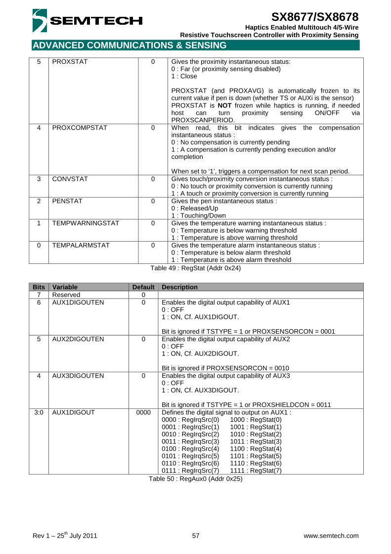
ADVANCED COMMUNICATIONS & SENSING
Rev 1 – 25th July 2011 57 www.semtech.com
SX8677/SX8678 Haptics Enabled Multitouch 4/5-Wire
Resistive Touchscreen Controller with Proximity Sensing
5 PROXSTAT
0 Gives the proximity instantaneous status: 0 : Far (or proximity sensing disabled) 1 : Close PROXSTAT (and PROXAVG) is automatically frozen to its current value if pen is down (whether TS or AUXi is the sensor) PROXSTAT is NOT frozen while haptics is running, if needed host can turn proximity sensing ON/OFF via PROXSCANPERIOD.
4 PROXCOMPSTAT
0 When read, this bit indicates gives the compensation instantaneous status : 0 : No compensation is currently pending 1 : A compensation is currently pending execution and/or completion When set to ‘1’, triggers a compensation for next scan period.
3 CONVSTAT
0 Gives touch/proximity conversion instantaneous status : 0 : No touch or proximity conversion is currently running 1 : A touch or proximity conversion is currently running
2 PENSTAT
0 Gives the pen instantaneous status : 0 : Released/Up 1 : Touching/Down
1 TEMPWARNINGSTAT
0 Gives the temperature warning instantaneous status : 0 : Temperature is below warning threshold 1 : Temperature is above warning threshold
0 TEMPALARMSTAT
0 Gives the temperature alarm instantaneous status : 0 : Temperature is below alarm threshold 1 : Temperature is above alarm threshold
Table 49 : RegStat (Addr 0x24)
Bits Variable Default Description
7 Reserved 0 6 AUX1DIGOUTEN 0 Enables the digital output capability of AUX1
0 : OFF 1 : ON, Cf. AUX1DIGOUT. Bit is ignored if TSTYPE = 1 or PROXSENSORCON = 0001
5 AUX2DIGOUTEN 0 Enables the digital output capability of AUX2 0 : OFF 1 : ON, Cf. AUX2DIGOUT. Bit is ignored if PROXSENSORCON = 0010
4 AUX3DIGOUTEN 0 Enables the digital output capability of AUX3 0 : OFF 1 : ON, Cf. AUX3DIGOUT. Bit is ignored if TSTYPE = 1 or PROXSHIELDCON = 0011
3:0 AUX1DIGOUT 0000 Defines the digital signal to output on AUX1 : 0000 : RegIrqSrc(0) 1000 : RegStat(0) 0001 : RegIrqSrc(1) 1001 : RegStat(1) 0010 : RegIrqSrc(2) 1010 : RegStat(2) 0011 : RegIrqSrc(3) 1011 : RegStat(3) 0100 : RegIrqSrc(4) 1100 : RegStat(4) 0101 : RegIrqSrc(5) 1101 : RegStat(5) 0110 : RegIrqSrc(6) 1110 : RegStat(6) 0111 : RegIrqSrc(7) 1111 : RegStat(7)
Table 50 : RegAux0 (Addr 0x25)

ADVANCED COMMUNICATIONS & SENSING
Rev 1 – 25th July 2011 58 www.semtech.com
SX8677/SX8678 Haptics Enabled Multitouch 4/5-Wire
Resistive Touchscreen Controller with Proximity Sensing
Bits Variable Default Description 7:4 AUX2DIGOUT 0000 Defines the digital signal to output on AUX2 :
0000 : RegIrqSrc(0) 1000 : RegStat(0) 0001 : RegIrqSrc(1) 1001 : RegStat(1) 0010 : RegIrqSrc(2) 1010 : RegStat(2) 0011 : RegIrqSrc(3) 1011 : RegStat(3) 0100 : RegIrqSrc(4) 1100 : RegStat(4) 0101 : RegIrqSrc(5) 1101 : RegStat(5) 0110 : RegIrqSrc(6) 1110 : RegStat(6) 0111 : RegIrqSrc(7) 1111 : RegStat(7)
3:0 AUX3DIGOUT 0000 Defines the digital signal to output on AUX3 : 0000 : RegIrqSrc(0) 1000 : RegStat(0) 0001 : RegIrqSrc(1) 1001 : RegStat(1) 0010 : RegIrqSrc(2) 1010 : RegStat(2) 0011 : RegIrqSrc(3) 1011 : RegStat(3) 0100 : RegIrqSrc(4) 1100 : RegStat(4) 0101 : RegIrqSrc(5) 1101 : RegStat(5) 0110 : RegIrqSrc(6) 1110 : RegStat(6) 0111 : RegIrqSrc(7) 1111 : RegStat(7)
Table 51 : RegAux1 (Addr 0x26)
Bits Variable Default Description 7:0 SOFTRESET 0x00 Writing 0xDE will reset the chip and all registers to their default
values. Table 52 : RegReset (Addr 0x3F)

ADVANCED COMMUNICATIONS & SENSING
Rev 1 – 25th July 2011 59 www.semtech.com
SX8677/SX8678 Haptics Enabled Multitouch 4/5-Wire
Resistive Touchscreen Controller with Proximity Sensing
13 APPLICATION INFORMATION
13.1 Typical Application Circuit
Figure 56 – Typical Application Circuit
13.2 External Components Recommended Values
Symbol Description Note Min Typ. Max Unit CVDD Main supply decoupling capacitor - 1 - uF
CMVDD Motor supply decoupling capacitor - 10 - uF CVREG Regulator decoupling capacitor +/- 20%, ESR<1Ω - 100 - nF RPULL Host interface pull-ups +/- 50% - 10 - kΩ
CTB Proximity sensor-to-shield capacitance - - <0.7 1.5 nF
RXY Proximity sensor serial resistor - - <1 1.5 kΩ RMOT Motor resistance - 7.5 - - Ω
CMOUT Motor output capacitor - - 1 - uF Table 53 : External Components Recommended Values
13.3 Multitouch Gestures
13.3.1 Pinch/Stretch A simple thumb and forefinger “pinch” movement enables a user to enlarge objects onscreen (moving fingers away from each other) or make them smaller (move them towards each other). This intuitive zooming function replaces the standard point-and-click functionality of a mouse and provides far greater accuracy to the user.
Figure 57 – Pinch/Stretch Multitouch Gestures

ADVANCED COMMUNICATIONS & SENSING
Rev 1 – 25th July 2011 60 www.semtech.com
SX8677/SX8678 Haptics Enabled Multitouch 4/5-Wire
Resistive Touchscreen Controller with Proximity Sensing
13.3.2 Rotate
Objects are rotated onscreen by making simple clockwise (right) or counterclockwise (left) movements with the anchored thumb and forefinger. This multi-touch function enables swift and accurate positioning of objects without needing to point and click repeatedly on a rotate left-right function button in order to achieve the desired effect.
Figure 58 – Rotate Multitouch Gestures

ADVANCED COMMUNICATIONS & SENSING
Rev 1 – 25th July 2011 61 www.semtech.com
SX8677/SX8678 Haptics Enabled Multitouch 4/5-Wire
Resistive Touchscreen Controller with Proximity Sensing
14 PACKAGING INFORMATION
14.1 QFN Package
Figure 59 - Outline Drawing - QFN
Figure 60 - Land Pattern - QFN

ADVANCED COMMUNICATIONS & SENSING
Rev 1 – 25th July 2011 62 www.semtech.com
SX8677/SX8678 Haptics Enabled Multitouch 4/5-Wire
Resistive Touchscreen Controller with Proximity Sensing
14.2 CSP Package
Figure 61 - Outline Drawing - CSP
Figure 62 - Land Pattern - CSP

ADVANCED COMMUNICATIONS & SENSING
Rev 1 – 25th July 2011 63 www.semtech.com
SX8677/SX8678 Haptics Enabled Multitouch 4/5-Wire
Resistive Touchscreen Controller with Proximity Sensing
Contact Information
© Semtech 2011 All rights reserved. Reproduction in whole or in part is prohibited without the prior written consent of the copyright owner. The information presented in this document does not form part of any quotation or contract, is believed to be accurate and reliable and may be changed without notice. No liability will be accepted by the publisher for any consequence of its use. Publication thereof does not convey nor imply any license under patent or other industrial or intellectual property rights. Semtech assumes no responsibility or liability whatsoever for any failure or unexpected operation resulting from misuse, neglect improper installation, repair or improper handling or unusual physical or electrical stress including, but not limited to, exposure to parameters beyond the specified maximum ratings or operation outside the specified range. SEMTECH PRODUCTS ARE NOT DESIGNED, INTENDED, AUTHORIZED OR WARRANTED TO BE SUITABLE FOR USE IN LIFE-SUPPORT APPLICATIONS, DEVICES OR SYSTEMS OR OTHER CRITICAL APPLICATIONS. INCLUSION OF SEMTECH PRODUCTS IN SUCH APPLICATIONS IS UNDERSTOOD TO BE UNDERTAKEN SOLELY AT THE CUSTOMER’S OWN RISK. Should a customer purchase or use Semtech products for any such unauthorized application, the customer shall indemnify and hold Semtech and its officers, employees, subsidiaries, affiliates, and distributors harmless against all claims, costs damages and attorney fees which could arise. Notice: All referenced brands, product names, service names and trademarks are the property of their respective owners.
Semtech Corporation Advanced Communications and Sensing Products Division 200 Flynn Road, Camarillo, CA 93012 Phone: (805) 498-2111 Fax: (805) 498-3804
Mouser Electronics
Authorized Distributor
Click to View Pricing, Inventory, Delivery & Lifecycle Information: Semtech:
SX8677IWLTRT SX8678IWLTRT SX8677ICSTRT SX8678ICSTRT