Embed Size (px)
Citation preview

326
ADVANCED COMBINATION PROBE FOR TESTING FERRITIC SEA-CURE CONDENSER
TUBING
Kenji Krzywosz, Electric Power Research Institute (EPRI),
Daniel Folsom, Tennessee Valley Authority (TVA), USA
ABSTRACT
As more condenser tubes are replaced with high performance, thin-walled ferritic stainless steel tubing
such as Sea-Cure and 2205 duplex, more attention is needed to address inspectability of such tubing,
especially in both tube free spans and tubes under support plates. EPRI has been examining this issue by
evaluating both mockups and field-removed tubes, and by conducting field trials utilizing both
magnetically-saturating eddy current probes as well as combination Saturn probes that inspect and
characterize both tube free spans and tubes under support plates using innovative probe designs.
This paper presents results of one such field evaluation by reviewing a field-acquired Sea-Cure
condenser tubing data from one of Pressurized Water Reactor (PWR) units in Tennessee. Also, details of
the selected Sea-Cure tubing mockup evaluation will be presented based on the application of the same
combination Saturn probe.
INTRODUCTION
The first part of the presentation involves evaluation and review of individual flaw types found in a
calibration standard along with the review of selected mockup tubing containing known flaw types at both
tube free spans and at tube-to-tube support intersections. This is followed by the evaluation of a field-
acquired data from Sea-Cure condenser tubing: 1.00” outer diameter (OD) by 0.028” nominal wall. It
should be noted that Sea-Cure is ferromagnetic with relative permeability values in the range of 30-100
[1].
To compensate for the ferromagnetic effect, a series of permanent magnets were placed next to
differential bobbin coils to axially saturate the tube wall with magnetizing field strength of around 1.3 K
gauss. This basically allowed establishment of phase angle-to-flaw depth calibration curves at selected
operating frequencies. The combination probe, in addition to the magnetically-saturating bobbin coils,
housed a set of six pancake array coils between the two transmitting bobbin coils to allow tube inspections
under tube support plates. This was accomplished in a partial-saturation, transmit-receive mode.
Generally, no inspection under the tube support plate (TSP) is possible due to interaction of permanent
magnets to carbon steel support plates resulting in large TSP signals. These TSP signals were difficult to
mix out due to variability of support plate and ferritic tubing signals resulting in less than desirable mix
residual signal outputs.
SEA-CURE REFERENCE STANDARD
Based on the application of the two-in-one combination probe, one ASME standard containing OD pits
and OD/ID grooves was used. OD pits found in the ASME standard were used to normalize and establish
the calibration curves for the magnetically-saturating bobbin coil probe at frequencies of 300k, 200k,
100k, and 50k. For array coils, tube end-to-tube end signals were used to normalize the amplitude and
phase angles of six individual pancake coils at frequencies of 75k, 50k, 30k, and 10k. Since these pancake
coil data were acquired as partial-saturation eddy current data, no phase angle-based calibration curves
were established. Therefore, these pancake coil channels were used primarily as detection channels in both
tube-free span regions and the vicinity of TSP regions. Figure 1 shows the drawing of the ASME standard
used to normalize and prepare bobbin coil calibration curves.

327
Figure 1 Sea-Cure Calibration Standard Drawing
SEA-CURE CALIBRATION STANDARD AND MOCKUP TUBING SIGNALS
The following frequency channels were used for acquisition and analysis of tubing conditions found in
Sea-Cure condenser tubing, 1.00” OD x 0.028” nominal wall:
• Differential bobbin coil phase angle channels: Channel 25-500 kHz; Channel 27-300 kHz;
Channel 29-100 khz; Channel 31-50 kHz
• Absolute bobbin coil amplitude channels: Channel 26-500 kHz Voltpeak-peak; Channel 28-300 kHz
Voltpeak-peak; Channel 30-100 kHz Voltpeak-peak; Channel 32-50 kHz Voltpeak-peak
• 75 kHz differential pancake coil: Channels 1 through 6
• 50 kHz differential pancake coil: Channels 7 through 12
• 30 kHz differential pancake coil: Channels 13 through 18
• 10 kHz differential pancake coil: Channels 19 through 24
The system configuration setting for the enhanced Saturn combination probe is shown as Figure 2.
It should be noted that coils 1 through 6 at time slots 1 through 4 were dedicated to six pancake coil
channels, all in differential mode to detect OD flaws at up to four different frequencies. As for one bobbin
probe, it was operated as coils 1 and 2 at time slots 13 through 16 to allow both differential and absolute
outputs at up to four different frequencies.

328
Figure 2 Eddy Current Configuration Settings for Combination Probe
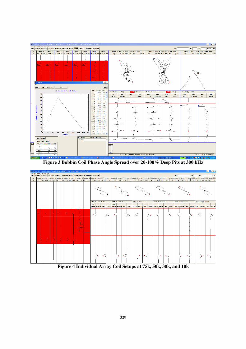
Figure 3 shows the combined ASME pit signals from the bobbin probe to show the phase angle
spread of 82º over the 20-100% flaw depth range at 300 kHz.
Figure 4 shows the phase angle setup of 215º for each of six pancake coil channels. Each of tube
end-to-tube end signals was adjusted individually for 250 Volt peak-to-peak at frequencies of 75k, 50k, 30k,
and 10k.
Figure 5 shows the resultant pancake coil phase angle spread between the 20% ID and 11% OD
groove signals at frequencies of 75k, 30k, and 10k. As expected, the overall phase angle differential
increased with lowering of operating frequencies: ∆27º at 75k, ∆87º at 30k, and ∆172º at 10k.
One key feature of the transmit-receive pancake coils signals to remember is the inverted phase
angles for ID and OD signals, for example, ID signals exhibit larger phase angles than OD phase angles as
shown in Figure 5.
329
Figure 3 Bobbin Coil Phase Angle Spread over 20-100% Deep Pits at 300 kHz
Figure 4 Individual Array Coil Setups at 75k, 50k, 30k, and 10k

330
Figure 5 Pancake Coil Phase Angle Differentials at 75k, 30k, and 10k
Using the established Saturn bobbin coil and pancake coil settings, several mockup tubing
indications were next evaluated; one in the tube free span and another in the vicinity of the tube-to-TSP
intersection. Figure 6 shows both conditions of a through-wall hole in the tube free span at 60º to 84º and
an OD wear of 64% wall loss under TSP at phase angles of 69º to 120º.
Note that individual pancake coil responses and the resultant phase angle orientations of the discreet
OD flaws under TSP in Figure 6 were quite different from the circumferential OD groove indications in
tube free spans of Figure 5. It’s entirely possible that carbon steel support plate may be affecting the flaw
indications found under TSP locations.

331
Figure 6 Bobbin/Pancake Coil Flaw Responses - Tube Free Spans and Under Support
EDDY CURRENT EVALUATION OF FIELD-ACQUIRED SEA-CURE CONDENSER TUBING
DATA
Of the 54 tubes selected and tested, four outcomes were observed: 1) OD flaw indications noted and
confirmed by both bobbin coil and pancake coil channels, 2) OD flaw indications noted by bobbin coil
channels but were not noted by pancake coil channels, 3) OD flaw indications noted by pancake coil
channel(s) but were not noted by bobbin coil channels, and 4) no OD flaw indications noted by either
bobbin coil or pancake coil channels.
The first three conditions will be presented separately in this paper. The fourth condition of not
registering any recordable flaw indications will not be covered as they merely indicate the absence of flaw
indications.
OD Flaw Indications Confirmed by Saturn Bobbin Coils and Pancake Coils
This section will present those detectable OD flaw indications confirmed by both bobbin and pancake coil
channels. It should be noted that this Saturn combination probe houses magnetically-saturating bobbin
coils using a set of axially-oriented permanent magnets, while six receiver coils with separate bobbin coil
transmitter coils were operated in a transmit-receive mode without the use of any permanent magnets.
Basically, the magnetically-biased bobbin coils provided the inspection coverage of the tube-free span
regions, while six pancake array receiver coils with separate bobbin transmitter coils not only covered the
tube-free span regions but extended the coverage to tube-to-carbon steel TSP intersections.
Figure 7 shows an example of an OD indication detected by both probe types. In some cases, up to
two pancake coils detected the same bobbin coil indication. Realizing that bobbin coils indicate the
indication to be an OD-initiated flaw, the pancake coils, however, showed phase angle orientations more
in line with an ID-initiating flaw.

332
Figure 7 OD Flaw Indication Confirmed by Saturn Bobbin and Pancake Coils
OD Flaw Indications by Saturn Bobbin but Not by Pancake Coils
This second case involves presence of an OD flaw-like indication by bobbin coils only. Detail review of
the associated pancake coil channels showed no associated ID or OD indications as shown in Figure 8.
Detail review of the individual bobbin coil channels showed that phase angles are increasing with
decreasing frequencies. This is just the opposite of what was expected of an OD flaw where phase angles
decrease with a decreasing frequency (see Figure 6). As such, such indications are believed to be deposits.
However, it is not well understood as to why such deposit signals are not observed by pancake array coils.

333
Figure 8 OD Flaw-Like Indication Confirmed by Saturn Bobbin but not by Pancake Coils
No OD Indications by Saturn Bobbin Coils but Detected by Saturn Array Coils
This last scenario involves absence of Saturn bobbin coil indications, but the review of individual pancake
coils showed presence of flaw-like indications. This condition occurs primarily at tube-to-TSP
intersections where no bobbin coil flaw signals are expected to be observed due to masking effect of large-
amplitude support plate signals.
Figure 9 presents comparison of normal support plate signals and flaw-like signals observed by
pancake array coils. Couple items to note are: 1) a flaw-like signal was found just in the vicinity of the
TSP and 2) pancake coil phase angles, once again, indicated the signal to be more like an ID indication.
Similar to field support plate signals, the mock-up based support plate signals by pancake coils
showed similar amplitude and phase angle orientations: 75k-17.22V/115°; 30k-15.05V/153°; 10k:-
8.87V/163°.

334
Figure 9 ID-Like Indication Confirmed by One of Saturn Pancake Coils at TSP
SUMMARY
The following observations are noted based on the inspection results of Sea-Cure ferritic tubing.
• Magnetically-biased Saturn bobbin coils were comparable for most part with magnetically-
saturating bobbin coils.
o Weaker permanent magnet field strength of Saturn probes resulted in increased tube noise for
some inspected tubes.
• Saturn probe extended the inspection coverage from tube free span to regions under support
plates.
• Saturn array coils provided confirmation of flaw-like signal at tube free span regions.
• Mockup flaw signals and field flaw signals are not quite consistent for pancake array coils – the
array coil field signals representing flaw-like indications fell into ID planes regardless of whether they
were found in tube free spans or in the vicinity of TSP.
• Tube pulls are needed to validate tube signals at support plate locations.
REFERENCE
1. K. Krzywosz, Nondestructive Evaluation: Advanced Nondestructive Evaluation Methods for
Testing Ferritic and Duplex Tubing, EPRI Report 1022932, October 2011.