Embed Size (px)
Citation preview
1
Advance Structural Analysis
Prof. Devdas Menon
Department of Civil Engineering
Indian Institute of Technology, Madras
Module No. # 2.5
Lecture No. # 11
Review of Basic Structural Analysis-2
Good morning to you.
(Refer Slide Time: 00:22)
We are now moving on to lecture11, in the second module, doing the Review of Basic
Structural Analysis.
2
(Refer Slide Time: 00:24)
We are going to start displacements methods in this session. It is something new to all of
you and something very different and very interesting compared to force methods. So,
this (Refer Slide Time: 00:38) is covered in part five of the book on Structural Analysis.
(Refer Slide Time: 00:42)
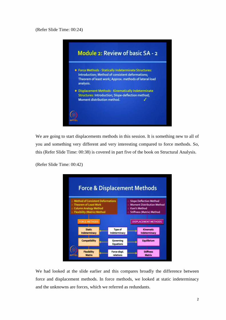
We had looked at the slide earlier and this compares broadly the difference between
force and displacement methods. In force methods, we looked at static indeterminacy
and the unknowns are forces, which we referred as redundants.
3
In displacement methods, we referred to kinematic indeterminacy. Here, the
displacements are the primary unknowns and the degrees of freedom. We solve for these
unknowns using compatibility equations in force methods and using equilibrium
equations in displacements methods. We cast the force displacement relations in a
flexibility format in the force methods and we do that using a stiffness format in the
displacement methods.
There are many force methods, but we had a close look in detail about the Method of
Consistent Deformations and the Theorem of Least Work. The Column Analogy method
is an excellent manual method, but we are not covering it in this scope and the Flexibility
Matrix Method is what we will look in detail, later.
In the stiffness methods, the earliest method is the slope deflection method, followed by
iterative solution procedures, the Moment Distribution Method due to Hardy Cross and
Kani’s method due to Gaspo Kani, which is similar to moment distribution methods. So,
we will not be covering Kani’s method in this course, but the most generalize method is
the stiffness matrix method, which we will look in real detail in the next modules.
(Refer Slide Time: 02:43)
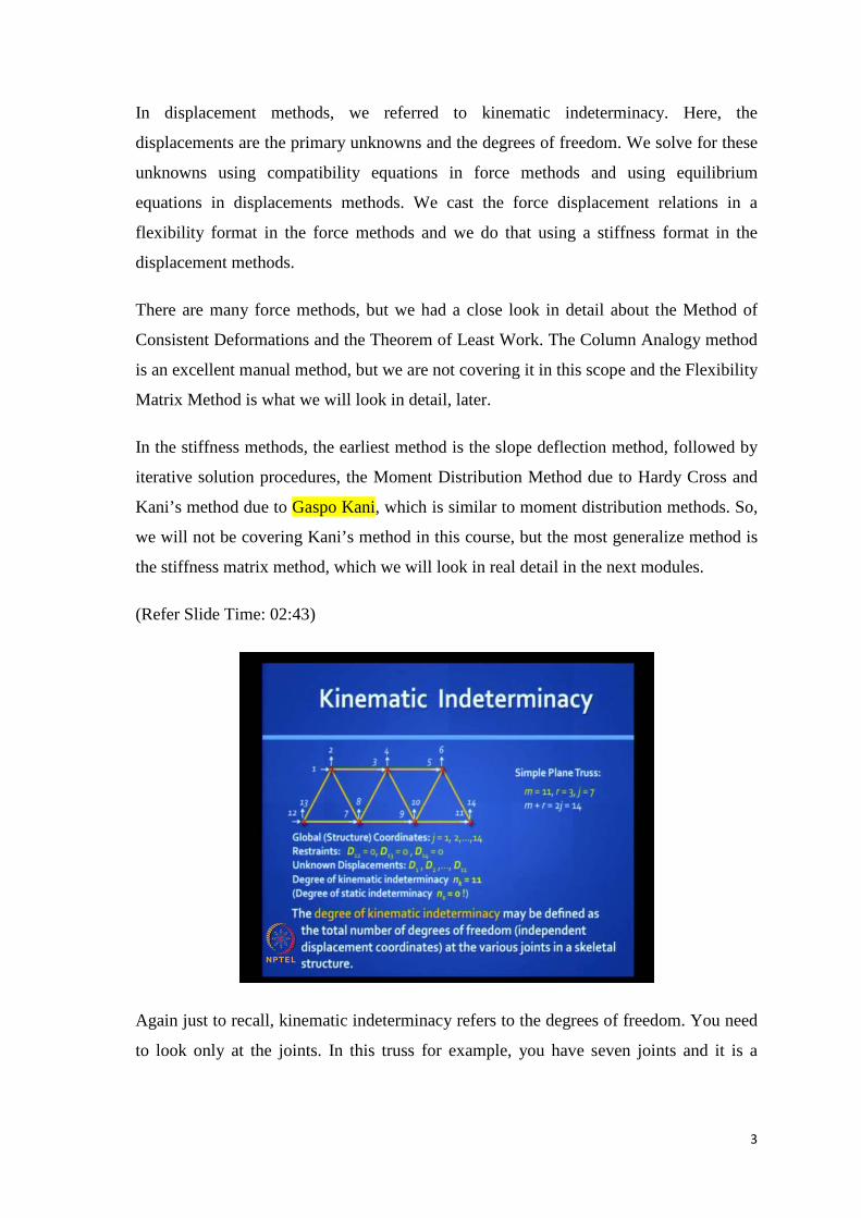
Again just to recall, kinematic indeterminacy refers to the degrees of freedom. You need
to look only at the joints. In this truss for example, you have seven joints and it is a
4
planar truss and each joint has 2 degrees of freedom, which we can mark using
coordinates as shown: 1, 2, 3, 4 and all the way to 11…14.
It is important to note that these fourteen displacements need not have any inter
relationship between them and they are really independent, but once you fix the
displacement vector, then you also fix the elongations in the parts. The relationship
between bar elongation and the displacements is referred to as compatibility relations.
For the truss to be stable, you need to arrest some of these displacements. In this case for
example, (Refer Slide Time: 03:47) if it simply supported, we should arrest at least three
of them.
So, let us say we arrest D12, D13 and D14 and usually while labeling them, we put the
arrested coordinates to the end of all labels. We begin with the free displacements and
we end with arrested displacements. The arrested displacements are those, where we
know for sure that the deflections are zero. So, there is nothing unknown about them and
the degree of kinematic indeterminacy refers to the unknown displacements. In this case,
it will be eleven and it is defined as a total number of degrees of freedom or independent
displacement coordinates at the various joints in a skeletal structure. So, in other words
we are able to locate this structure in its deformed configuration with reference to its
original configuration. Once you know that the joints are located in a certain manner, we
can really interpolate and get the location of any point on that structure in any bar with
reference to those joints locations.
5
(Refer Slide Time: 04:58)
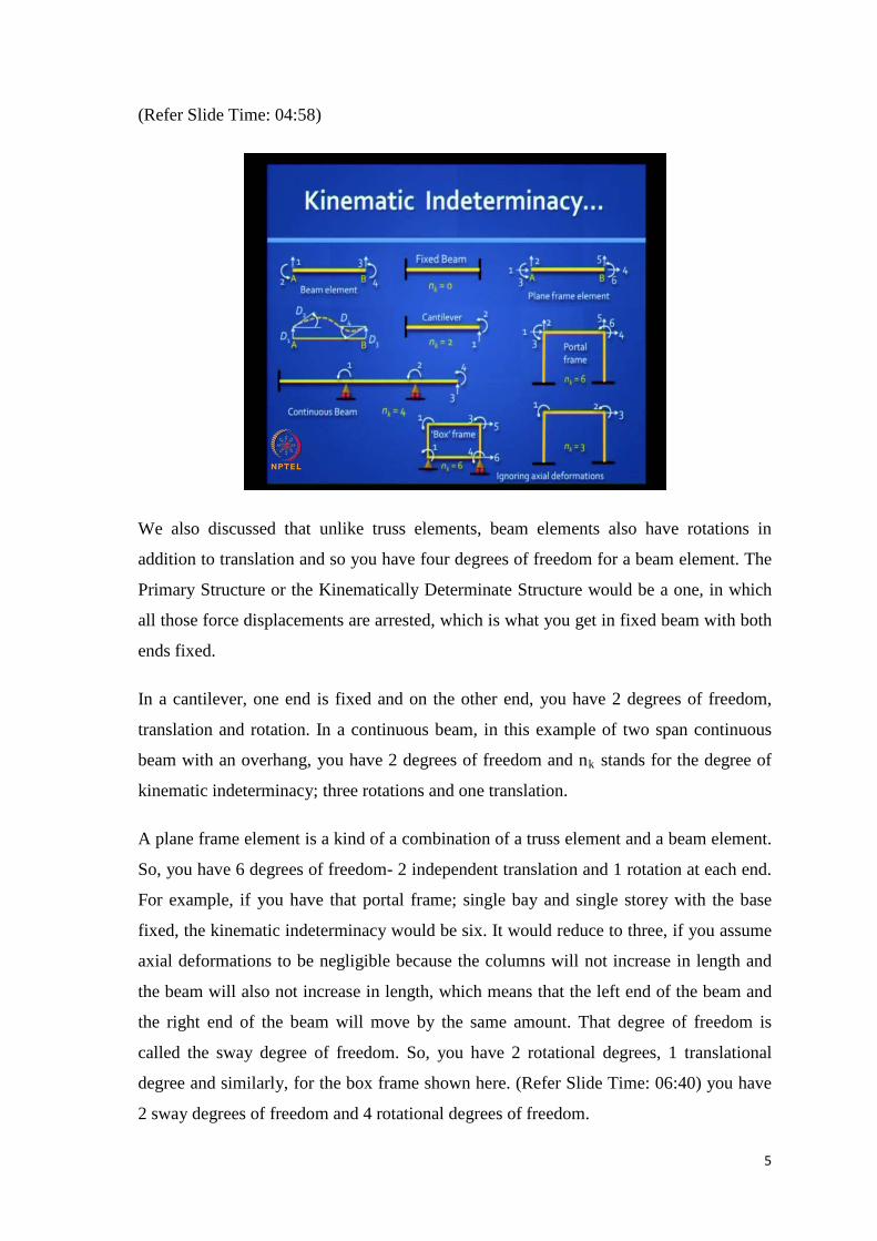
We also discussed that unlike truss elements, beam elements also have rotations in
addition to translation and so you have four degrees of freedom for a beam element. The
Primary Structure or the Kinematically Determinate Structure would be a one, in which
all those force displacements are arrested, which is what you get in fixed beam with both
ends fixed.
In a cantilever, one end is fixed and on the other end, you have 2 degrees of freedom,
translation and rotation. In a continuous beam, in this example of two span continuous
beam with an overhang, you have 2 degrees of freedom and nk stands for the degree of
kinematic indeterminacy; three rotations and one translation.
A plane frame element is a kind of a combination of a truss element and a beam element.
So, you have 6 degrees of freedom- 2 independent translation and 1 rotation at each end.
For example, if you have that portal frame; single bay and single storey with the base
fixed, the kinematic indeterminacy would be six. It would reduce to three, if you assume
axial deformations to be negligible because the columns will not increase in length and
the beam will also not increase in length, which means that the left end of the beam and
the right end of the beam will move by the same amount. That degree of freedom is
called the sway degree of freedom. So, you have 2 rotational degrees, 1 translational
degree and similarly, for the box frame shown here. (Refer Slide Time: 06:40) you have
2 sway degrees of freedom and 4 rotational degrees of freedom.
6
(Refer Slide Time: 06:46)
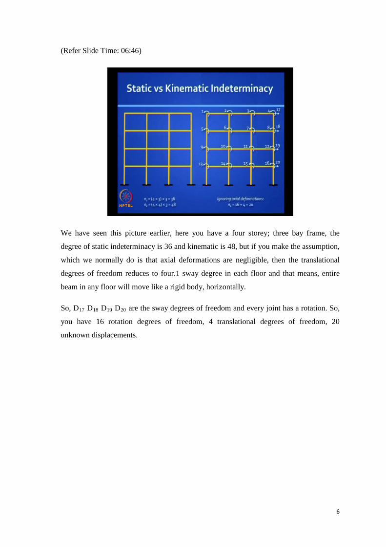
We have seen this picture earlier, here you have a four storey; three bay frame, the
degree of static indeterminacy is 36 and kinematic is 48, but if you make the assumption,
which we normally do is that axial deformations are negligible, then the translational
degrees of freedom reduces to four.1 sway degree in each floor and that means, entire
beam in any floor will move like a rigid body, horizontally.
So, D17 D18 D19 D20 are the sway degrees of freedom and every joint has a rotation. So,
you have 16 rotation degrees of freedom, 4 translational degrees of freedom, 20
unknown displacements.
7
(Refer Slide Time: 07:33)
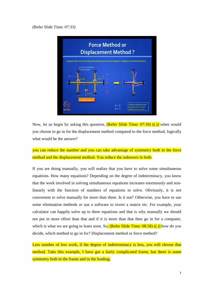
Now, let us begin by asking this question, (Refer Slide Time: 07:39) ((.)) when would
you choose to go in for the displacement method compared to the force method, logically
what would be the answer?
you can reduce the number and you can take advantage of symmetry both in the force
method and the displacement method. You reduce the unknown in both.
If you are doing manually, you will realize that you have to solve some simultaneous
equations. How many equations? Depending on the degree of indeterminacy, you know
that the work involved in solving simultaneous equations increases enormously and non-
linearly with the function of numbers of equations to solve. Obviously, it is not
convenient to solve manually for more than three. Is it not? Otherwise, you have to use
some elimination methods or use a software to invert a matrix etc. For example, your
calculator can happily solve up to three equations and that is why manually we should
not put in more effort than that and if it is more than that then go in for a computer,
which is what we are going to learn soon. So, (Refer Slide Time: 08:58) ((.)) how do you
decide, which method to go in for? Displacement method or force method?
Less number of less work, if the degree of indeterminacy is less, you will choose that
method. Take this example, I have got a fairly complicated frame, but there is some
symmetry both in the frame and in the loading.
8
(Refer Slide Time: 09:24) ((.)) Which method would you go? How long would it take
you to solve this by the force method that you know?
Indeterminacy is more how much it here in it is only one. first let us take advantage of
symmetry. so, let us cut the beam at the center at c. The appropriate boundary condition
is a guided roller support because in rotation, there is zero but it can reflect. So, let us
look at this reduced frame (Refer Slide Time: 09:56). Let us neglect axial deformations.
Tell me, what is the degree of static indeterminacy? If it is just a cantilever, it is
determinate. So, you got some extra reactions coming there. How many of them? (Refer
Slide Time: 10:13) ((.))
one two three four five six seven seven sir seven four. Well, at that hinge support, you
have two and in that guided roller support, you have two. You have a horizontal reaction
also possible and at that top you can have one vertical reaction. So, that makes it five.
What about the unknown rotations? At the fixed end A, you do not have any unknowns.
At D, you potentially have a rotation and translation. At C, you have a translation and
rotation is zero. So, 2 plus 1 is 3. At B, you have a rotation, four and at O, you have a
rotation, O is also a joint. So, you have five. Is it clear? (Refer Slide Time: 11:19)
sorry ((noise)) only a rotation at O and B, only rotations at D rotation and translation at
C. So, you have five and so it looks likes they are competing, but actually that five
reduces to one. So, you will find that this is a problem that you can solve in one minute,
if you are very alert and you understand the beauty of looking at the displaced
configuration. We will see this problem shortly.
So, in this we will first discuss. Before getting into solving problems in the hard way, let
us first get a broad introduction about displacements methods. So, we should understand
the meaning of stiffness. So, take this example (Refer Slide Time: 12:06) of a simply
supported beam subjected to an end moment M0. You can find a relationship between
the rotations, you have a clockwise rotation at O and an anti clockwise rotation at A. you
can get a relationship between M0 and theta. You just have to use a conjugate beam
method. Can you tell me that relationship? Mo is equal to or theta is equal to Mo by
(Refer Slide Time: 12:49) ((noise))
9
(Refer Slide Time: 13:00)
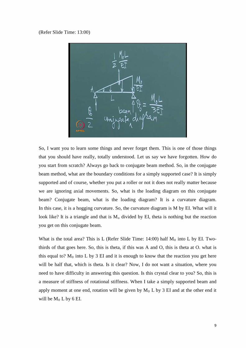
So, I want you to learn some things and never forget them. This is one of those things
that you should have really, totally understood. Let us say we have forgotten. How do
you start from scratch? Always go back to conjugate beam method. So, in the conjugate
beam method, what are the boundary conditions for a simply supported case? It is simply
supported and of course, whether you put a roller or not it does not really matter because
we are ignoring axial movements. So, what is the loading diagram on this conjugate
beam? Conjugate beam, what is the loading diagram? It is a curvature diagram.
In this case, it is a hogging curvature. So, the curvature diagram is M by EI. What will it
look like? It is a triangle and that is Mo divided by EI, theta is nothing but the reaction
you get on this conjugate beam.
What is the total area? This is L (Refer Slide Time: 14:00) half M0 into L by EI. Two-
thirds of that goes here. So, this is theta, if this was A and O, this is theta at O. what is
this equal to? M0 into L by 3 EI and it is enough to know that the reaction you get here
will be half that, which is theta. Is it clear? Now, I do not want a situation, where you
need to have difficulty in answering this question. Is this crystal clear to you? So, this is
a measure of stiffness of rotational stiffness. When I take a simply supported beam and
apply moment at one end, rotation will be given by M0 L by 3 EI and at the other end it
will be M0 L by 6 EI.
10
(Refer Slide Time: 15:03)
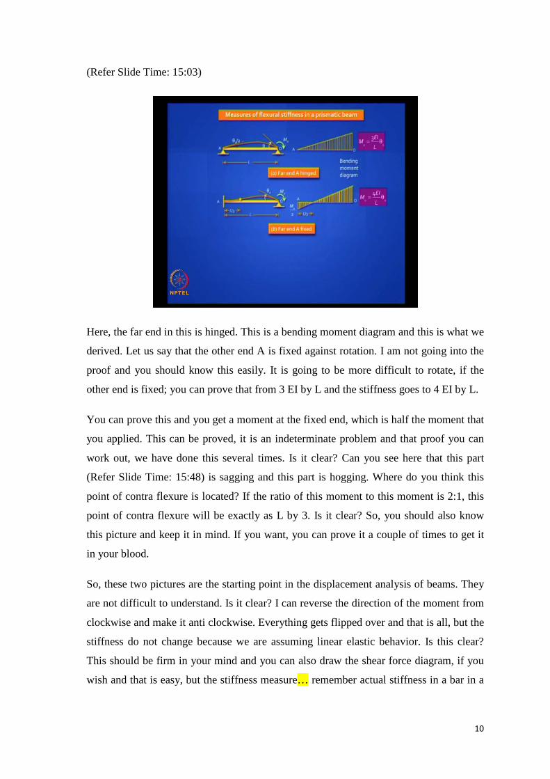
Here, the far end in this is hinged. This is a bending moment diagram and this is what we
derived. Let us say that the other end A is fixed against rotation. I am not going into the
proof and you should know this easily. It is going to be more difficult to rotate, if the
other end is fixed; you can prove that from 3 EI by L and the stiffness goes to 4 EI by L.
You can prove this and you get a moment at the fixed end, which is half the moment that
you applied. This can be proved, it is an indeterminate problem and that proof you can
work out, we have done this several times. Is it clear? Can you see here that this part
(Refer Slide Time: 15:48) is sagging and this part is hogging. Where do you think this
point of contra flexure is located? If the ratio of this moment to this moment is 2:1, this
point of contra flexure will be exactly as L by 3. Is it clear? So, you should also know
this picture and keep it in mind. If you want, you can prove it a couple of times to get it
in your blood.
So, these two pictures are the starting point in the displacement analysis of beams. They
are not difficult to understand. Is it clear? I can reverse the direction of the moment from
clockwise and make it anti clockwise. Everything gets flipped over and that is all, but the
stiffness do not change because we are assuming linear elastic behavior. Is this clear?
This should be firm in your mind and you can also draw the shear force diagram, if you
wish and that is easy, but the stiffness measure… remember actual stiffness in a bar in a
11
truss element, (Refer Slide Time: 16:58) what is axial stiffness? EA by L because we are
relating axial force N with what? With elongation E.
N, the axial force is E A by L times elongation, when you talk about a beam you do not
talk about a force and a translation, but you talk about a moment and a rotation. Is it
clear? There are many ways of describing it and this is one way, you apply a moment at
one end, if your beam is stiffer, it will be more difficult to rotate it. So, the flexural
rigidity of the beam comes in the numerator, that is EI and the length of the beam comes
in the denominator and there is constant, which depends on the boundary conditions. If
the far end is simply supported, it is hinged and then it is 3I by L. If the far end is fixed,
it is 4 EI by L.
(Refer Slide Time: 18:03)
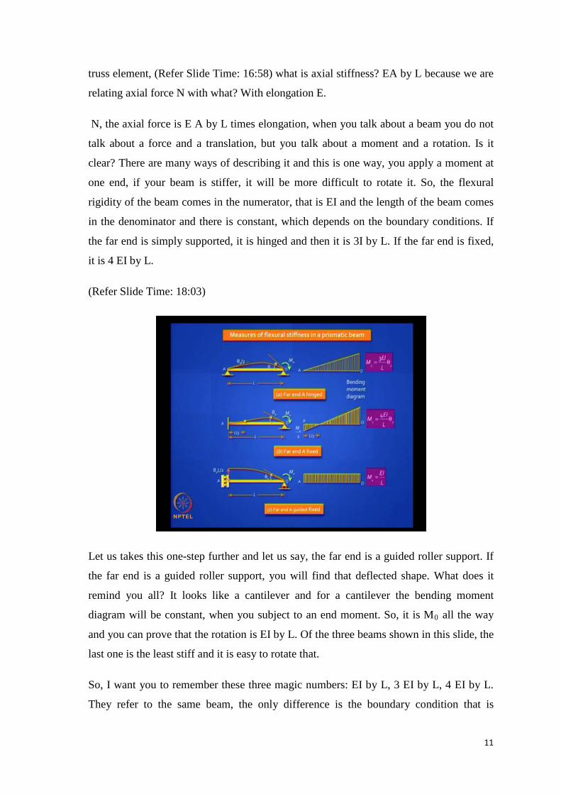
Let us takes this one-step further and let us say, the far end is a guided roller support. If
the far end is a guided roller support, you will find that deflected shape. What does it
remind you all? It looks like a cantilever and for a cantilever the bending moment
diagram will be constant, when you subject to an end moment. So, it is M0 all the way
and you can prove that the rotation is EI by L. Of the three beams shown in this slide, the
last one is the least stiff and it is easy to rotate that.
So, I want you to remember these three magic numbers: EI by L, 3 EI by L, 4 EI by L.
They refer to the same beam, the only difference is the boundary condition that is
12
different at the far end. See, it is a same M0. In this beam, (Refer Slide Time: 19:08) you
are not allowing any translation, but your allowing free rotation.
Here, you are not allowing translation or rotation. Here, (Refer Slide Time: 19:25) you
are allowing translation, but you are arresting rotation. Is it clear? So, they are different
degrees of stiffness, but these three numbers, you remember? This is pure bending in the
last case. So, you have a uniform bending moment diagram and so these three are worth
remembering because you can take lot of shortcuts, if you can invoke this understanding.
Traditionally, you arrest all degrees of freedom in the displacement method and get your
primary structure, but if you can modify those stiffnesses for these three cases. Your
degree of indeterminacy drastically reduces and we have to take advantage of that.
(Refer Slide Time: 20:03)
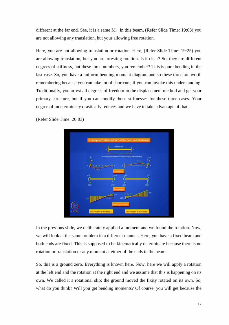
In the previous slide, we deliberately applied a moment and we found the rotation. Now,
we will look at the same problem in a different manner. Here, you have a fixed beam and
both ends are fixed. This is supposed to be kinematically determinate because there is no
rotation or translation or any moment at either of the ends in the beam.
So, this is a ground zero. Everything is known here. Now, here we will apply a rotation
at the left end and the rotation at the right end and we assume that this is happening on its
own. We called it a rotational slip; the ground moved the fixity rotated on its own. So,
what do you think? Will you get bending moments? Of course, you will get because the
13
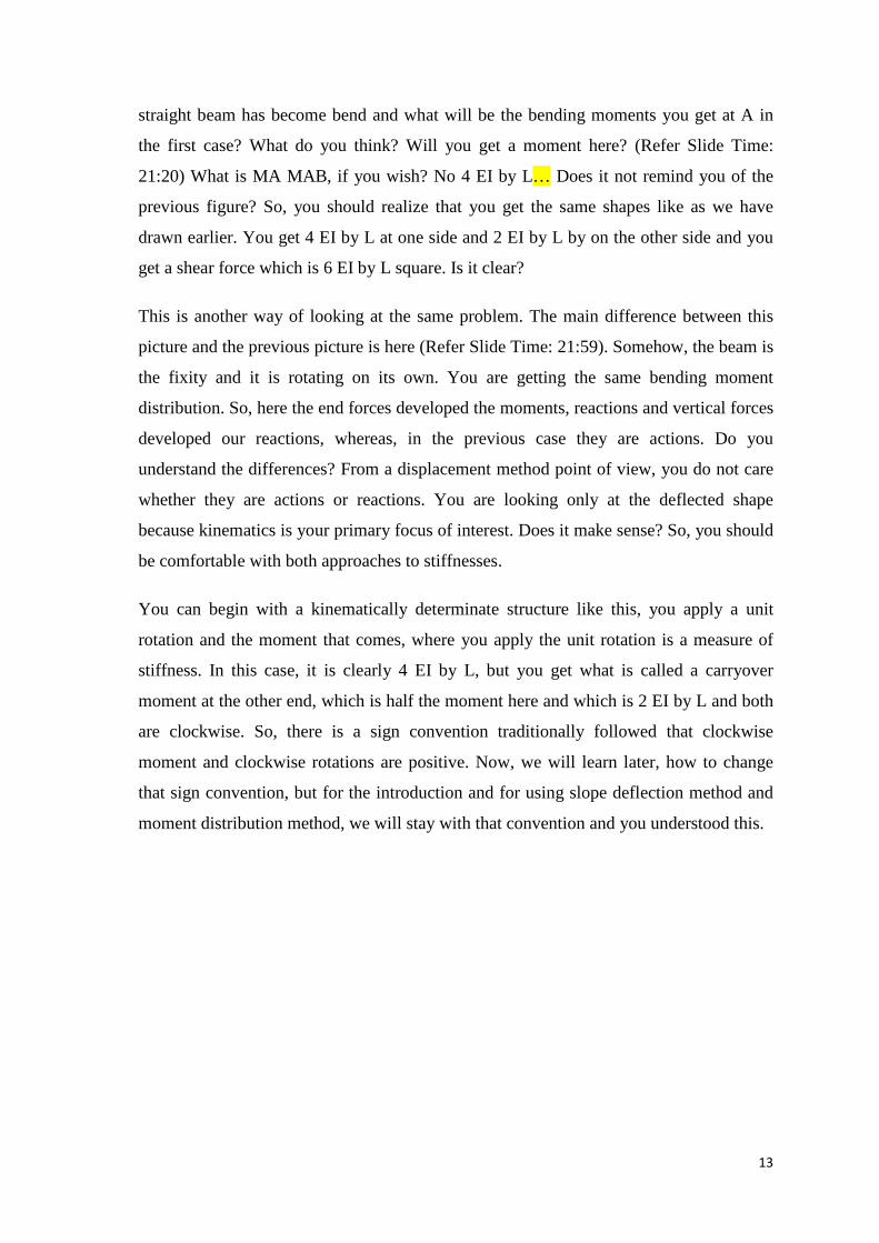
straight beam has become bend and what will be the bending moments you get at A in
the first case? What do you think? Will you get a moment here? (Refer Slide Time:
21:20) What is MA MAB, if you wish? No 4 EI by L… Does it not remind you of the
previous figure? So, you should realize that you get the same shapes like as we have
drawn earlier. You get 4 EI by L at one side and 2 EI by L by on the other side and you
get a shear force which is 6 EI by L square. Is it clear?
This is another way of looking at the same problem. The main difference between this
picture and the previous picture is here (Refer Slide Time: 21:59). Somehow, the beam is
the fixity and it is rotating on its own. You are getting the same bending moment
distribution. So, here the end forces developed the moments, reactions and vertical forces
developed our reactions, whereas, in the previous case they are actions. Do you
understand the differences? From a displacement method point of view, you do not care
whether they are actions or reactions. You are looking only at the deflected shape
because kinematics is your primary focus of interest. Does it make sense? So, you should
be comfortable with both approaches to stiffnesses.
You can begin with a kinematically determinate structure like this, you apply a unit
rotation and the moment that comes, where you apply the unit rotation is a measure of
stiffness. In this case, it is clearly 4 EI by L, but you get what is called a carryover
moment at the other end, which is half the moment here and which is 2 EI by L and both
are clockwise. So, there is a sign convention traditionally followed that clockwise
moment and clockwise rotations are positive. Now, we will learn later, how to change
that sign convention, but for the introduction and for using slope deflection method and
moment distribution method, we will stay with that convention and you understood this.
14
(Refer Slide Time: 23:28)
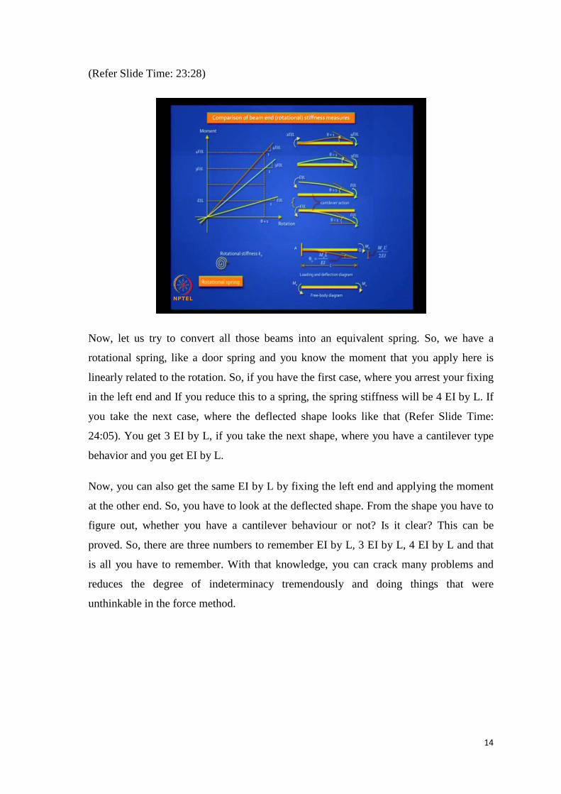
Now, let us try to convert all those beams into an equivalent spring. So, we have a
rotational spring, like a door spring and you know the moment that you apply here is
linearly related to the rotation. So, if you have the first case, where you arrest your fixing
in the left end and If you reduce this to a spring, the spring stiffness will be 4 EI by L. If
you take the next case, where the deflected shape looks like that (Refer Slide Time:
24:05). You get 3 EI by L, if you take the next shape, where you have a cantilever type
behavior and you get EI by L.
Now, you can also get the same EI by L by fixing the left end and applying the moment
at the other end. So, you have to look at the deflected shape. From the shape you have to
figure out, whether you have a cantilever behaviour or not? Is it clear? This can be
proved. So, there are three numbers to remember EI by L, 3 EI by L, 4 EI by L and that
is all you have to remember. With that knowledge, you can crack many problems and
reduces the degree of indeterminacy tremendously and doing things that were
unthinkable in the force method.
15
(Refer Slide Time: 24:57)
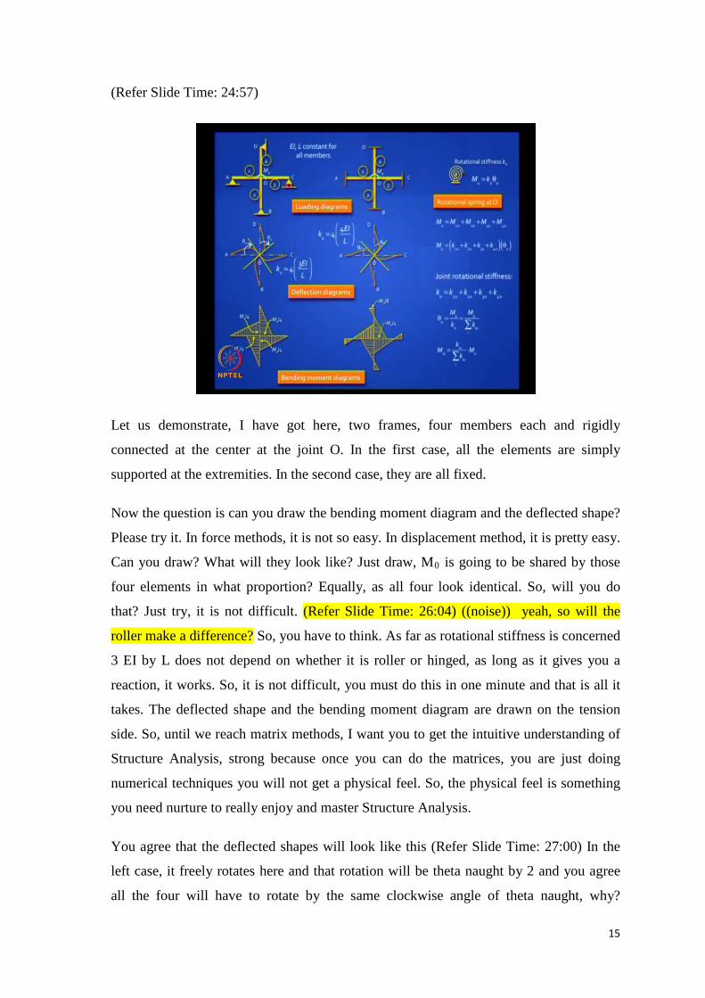
Let us demonstrate, I have got here, two frames, four members each and rigidly
connected at the center at the joint O. In the first case, all the elements are simply
supported at the extremities. In the second case, they are all fixed.
Now the question is can you draw the bending moment diagram and the deflected shape?
Please try it. In force methods, it is not so easy. In displacement method, it is pretty easy.
Can you draw? What will they look like? Just draw, M0 is going to be shared by those
four elements in what proportion? Equally, as all four look identical. So, will you do
that? Just try, it is not difficult. (Refer Slide Time: 26:04) ((noise)) yeah, so will the
roller make a difference? So, you have to think. As far as rotational stiffness is concerned
3 EI by L does not depend on whether it is roller or hinged, as long as it gives you a
reaction, it works. So, it is not difficult, you must do this in one minute and that is all it
takes. The deflected shape and the bending moment diagram are drawn on the tension
side. So, until we reach matrix methods, I want you to get the intuitive understanding of
Structure Analysis, strong because once you can do the matrices, you are just doing
numerical techniques you will not get a physical feel. So, the physical feel is something
you need nurture to really enjoy and master Structure Analysis.
You agree that the deflected shapes will look like this (Refer Slide Time: 27:00) In the
left case, it freely rotates here and that rotation will be theta naught by 2 and you agree
all the four will have to rotate by the same clockwise angle of theta naught, why?
16
Because the joint is rigid. That is a correct answer and here also, it will rotate by
something, which I have referred to as theta0 with the tilde. Which rotation will be more,
the one on the right side or the left side? Left side because this is stiffer and it is stiffer
because here, at all the other beam ends, you are not permitting any rotation. You have a
point of contra flexure in the middle.
Now, can you draw the bending moment diagram? It is Easy, so you can look at it as a
spring and the spring stiffness is K0. What is the value of K0 in the first case? What is
the value K0 in the second case? What is K0 in the first case? It is 3 EI by L and that is
for one beam. You have four of them. (Refer Slide Time: 28:31) Divide by four or
multiply by 4? why multiply by 4?((.))
M0 by four it is what is K0 what is supposing replace that i replace that whole frame with
the spring as i showed here tell me give me an expression for K0 ah So, you are
multiplying. In other words, do you agree that the stiffnesses of all the connecting
members will add up? They will add up. Why will they add up? Because equilibrium
demands that they add up.So, let us say there are four elements. Do you agree that
equilibrium demands that M0 will be the sum of all those four beam element ends? For
each of them, you can see K10 into theta0, K20 into theta0 etc.
We said in Structural Analysis, you should be sensitive to three things- one is
equilibrium or forces and moments, second is compatibility and this is what made you
say that theta0 is common for all the four members and the third thing is the force
displacement relationship, which is where K0 comes into play. is it clear? So, we are
invoking all three. Now, this is the reason, why M10 naught is K10 into theta0, M2 is K2o
into theta0 etc. we said M0is K0 into theta0 and this is why we say K naught is the sum of
the individual element stiffness. This is the proof that the stiffnesses add up and if you
find the stiffness of all four are equal, find the stiffness of one beam element and
multiply by 4 and not divide by 4. It increases and it becomes stiffer. It is easier to rotate
one element than to rotate all four simultaneously, we have to apply that much extra
moment. So, theta0 can be calculated in that manner and in the first case, it will be four
times 3 EI by L in the second case, it will be four times 4 EI by L.
So, now you are comfortably with that. What about the bending moment diagrams drawn
on the tension side? Did you draw it that way? How many of you in this class drew the
17
bending moment diagrams correctly? What happened to the rest of you? Is this difficult,
tell me? Is it difficult to draw? M0 gets shared. M0 by 4, it is a linear varying diagram.
Where is tension? It is clearly in the direction shown. The moment at the other end is
zero. In the other case, there is a carryover moment of M0 by 8. Does it make sense now?
So, I want to you slowly get into the groove and understand, how powerful is this
method.
(Refer Slide Time: 31:50)
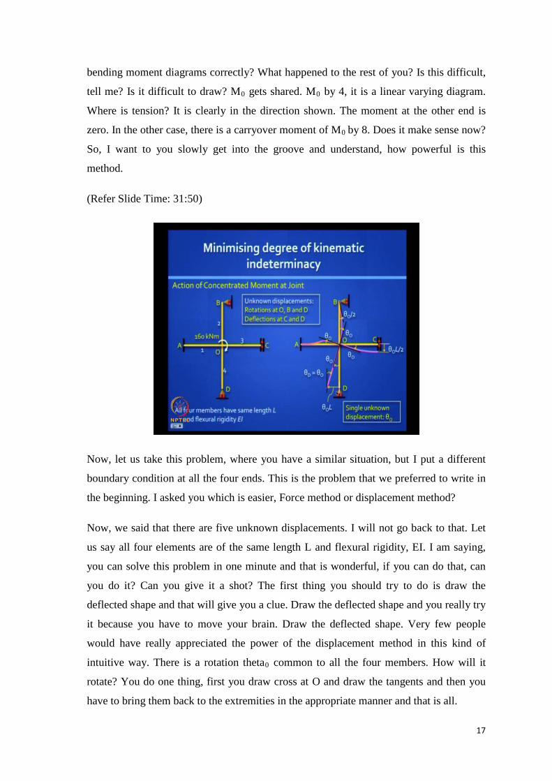
Now, let us take this problem, where you have a similar situation, but I put a different
boundary condition at all the four ends. This is the problem that we preferred to write in
the beginning. I asked you which is easier, Force method or displacement method?
Now, we said that there are five unknown displacements. I will not go back to that. Let
us say all four elements are of the same length L and flexural rigidity, EI. I am saying,
you can solve this problem in one minute and that is wonderful, if you can do that, can
you do it? Can you give it a shot? The first thing you should try to do is draw the
deflected shape and that will give you a clue. Draw the deflected shape and you really try
it because you have to move your brain. Draw the deflected shape. Very few people
would have really appreciated the power of the displacement method in this kind of
intuitive way. There is a rotation theta0 common to all the four members. How will it
rotate? You do one thing, first you draw cross at O and draw the tangents and then you
have to bring them back to the extremities in the appropriate manner and that is all.
18
Have you done it? So, I will reveal it to you and this is what it should look like (Refer
Slide Time: 33:48). An amazing thing you discover, what do you discover? I drew this
cross and set everything to rotate by theta naught. So, this first beam must come back
here. This must come back there and you remember that if this is theta0 and this will be
half theta0 (Refer Slide Time: 34:12). This will rotate theta naught this way and you can
prove that this deflection is related to theta0. So, it is theta0 L by 2. There is no reaction
here and so this is going to rotate like a rigid body and if theta0 is small, this is theta0 into
L. so, what do you conclude? There are really no five independent rotations and
translations. There is just one unknown, theta naught and so it is not difficult do. So, can
you find the bending moments now?
(Refer Slide Time: 34:49)
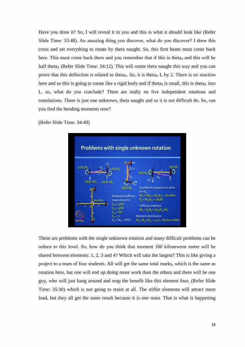
These are problems with the single unknown rotation and many difficult problems can be
reduce to this level. So, how do you think that moment 160 kilonewton meter will be
shared between elements: 1, 2, 3 and 4? Which will take the largest? This is like giving a
project to a team of four students. All will get the same total marks, which is the same as
rotation here, but one will end up doing more work than the others and there will be one
guy, who will just hang around and reap the benefit like this element four, (Refer Slide
Time: 35:30) which is not going to resist at all. The stiffer elements will attract more
load, but they all get the same result because it is one team. That is what is happening
19
here. So, it is depicting of law of nature.(Refer Slide Time: 35:51) Which is the stiffest
among those four?((.))
One, two, three, four. What is stiffness of 1? 4 EI by L, very good. stiffness of 2? 3 EI by
L ,stiffness of 3? EI by L and stiffness of 4? Zero .Now, tell me what is the moment
going to 1? four three two one zero thoroughly EI by L you got the ratio’s now four M
not by two eighty what goes to element two sixty what goes element three twenty do you
get any moments at the extreme ends at A do you get something you get half of eighty in
the same direction
Now, can you please draw the bending moment diagram on our own? You got the
answers intuitively. So, draw it. You can expect simple questions like this in your
coming quiz, all 1 minute answers, but you can take ten minutes if you wish, but if you
solve for five unknowns, it will take you one day. You draw it consistently on the
tensions side. So, all that is something you must have learnt by now. It is not difficult
and I want all of you to master this. Everyone in this class should understand this and
should be able to do it correctly. Again, only when look at the deflection shape, you will
know, which the tension side is. Otherwise, you will be doing it wrongly, as I can see
some of you are doing it.
Which is the tension side? Draw the deflected shape. (Refer Slide Time: 37:48) So, this
is the first element 4 EI by L, this is the second element 3 EI by L, this is the third
element EI by L and the fourth is not worth drawing, it is a straight line. These are the
stiffnesses. This is a 160 kilonewton and total stiffness adds up to 20 EI by L and the
ratio is 4:3:1 and by the way this is moment distribution, you are distributing that 160 to
the 4 elements in that ratio, 4:3:1:0. You correctly said 80:6:20.
20
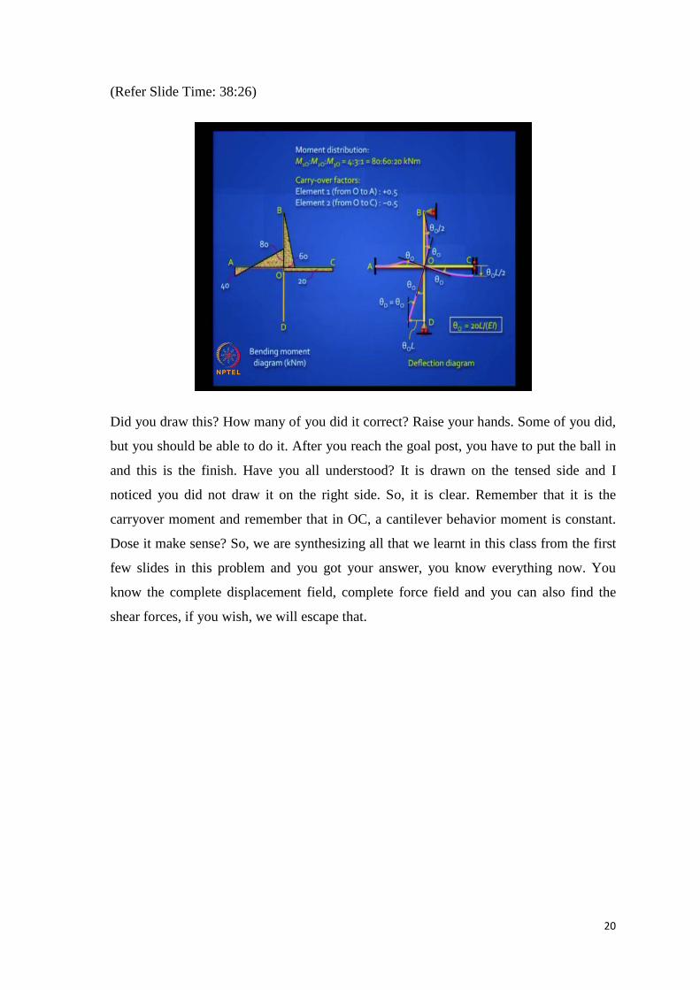
(Refer Slide Time: 38:26)
Did you draw this? How many of you did it correct? Raise your hands. Some of you did,
but you should be able to do it. After you reach the goal post, you have to put the ball in
and this is the finish. Have you all understood? It is drawn on the tensed side and I
noticed you did not draw it on the right side. So, it is clear. Remember that it is the
carryover moment and remember that in OC, a cantilever behavior moment is constant.
Dose it make sense? So, we are synthesizing all that we learnt in this class from the first
few slides in this problem and you got your answer, you know everything now. You
know the complete displacement field, complete force field and you can also find the
shear forces, if you wish, we will escape that.
21
(Refer Slide Time: 39:19)
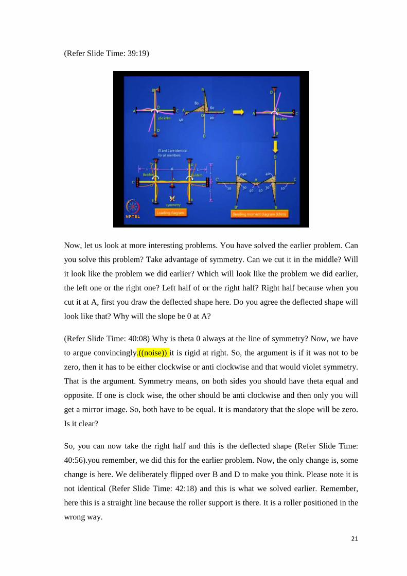
Now, let us look at more interesting problems. You have solved the earlier problem. Can
you solve this problem? Take advantage of symmetry. Can we cut it in the middle? Will
it look like the problem we did earlier? Which will look like the problem we did earlier,
the left one or the right one? Left half of or the right half? Right half because when you
cut it at A, first you draw the deflected shape here. Do you agree the deflected shape will
look like that? Why will the slope be 0 at A?
(Refer Slide Time: 40:08) Why is theta 0 always at the line of symmetry? Now, we have
to argue convincingly.((noise)) it is rigid at right. So, the argument is if it was not to be
zero, then it has to be either clockwise or anti clockwise and that would violet symmetry.
That is the argument. Symmetry means, on both sides you should have theta equal and
opposite. If one is clock wise, the other should be anti clockwise and then only you will
get a mirror image. So, both have to be equal. It is mandatory that the slope will be zero.
Is it clear?
So, you can now take the right half and this is the deflected shape (Refer Slide Time:
40:56).you remember, we did this for the earlier problem. Now, the only change is, some
change is here. We deliberately flipped over B and D to make you think. Please note it is
not identical (Refer Slide Time: 42:18) and this is what we solved earlier. Remember,
here this is a straight line because the roller support is there. It is a roller positioned in the
wrong way.
22
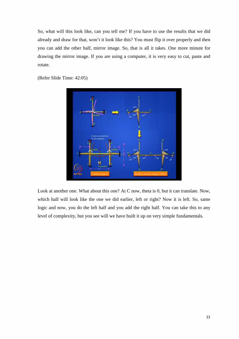
So, what will this look like, can you tell me? If you have to use the results that we did
already and draw for that, won’t it look like this? You must flip it over properly and then
you can add the other half, mirror image. So, that is all it takes. One more minute for
drawing the mirror image. If you are using a computer, it is very easy to cut, paste and
rotate.
(Refer Slide Time: 42:05)
Look at another one. What about this one? At C now, theta is 0, but it can translate. Now,
which half will look like the one we did earlier, left or right? Now it is left. So, same
logic and now, you do the left half and you add the right half. You can take this to any
level of complexity, but you see will we have built it up on very simple fundamentals.
23
(Refer Slide Time: 42:34)
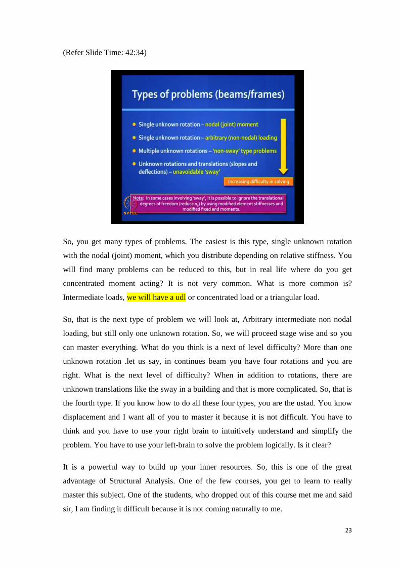
So, you get many types of problems. The easiest is this type, single unknown rotation
with the nodal (joint) moment, which you distribute depending on relative stiffness. You
will find many problems can be reduced to this, but in real life where do you get
concentrated moment acting? It is not very common. What is more common is?
Intermediate loads, we will have a udl or concentrated load or a triangular load.
So, that is the next type of problem we will look at, Arbitrary intermediate non nodal
loading, but still only one unknown rotation. So, we will proceed stage wise and so you
can master everything. What do you think is a next of level difficulty? More than one
unknown rotation .let us say, in continues beam you have four rotations and you are
right. What is the next level of difficulty? When in addition to rotations, there are
unknown translations like the sway in a building and that is more complicated. So, that is
the fourth type. If you know how to do all these four types, you are the ustad. You know
displacement and I want all of you to master it because it is not difficult. You have to
think and you have to use your right brain to intuitively understand and simplify the
problem. You have to use your left-brain to solve the problem logically. Is it clear?
It is a powerful way to build up your inner resources. So, this is one of the great
advantage of Structural Analysis. One of the few courses, you get to learn to really
master this subject. One of the students, who dropped out of this course met me and said
sir, I am finding it difficult because it is not coming naturally to me.
24
There is an old Chinese saying, if you want to eat roast duck and decide to eat roast duck
by standing on a mountaintop with your mouth open waiting for it to drop, you will have
to wait for a very long time. You see, if you really want to develop your brains cells,
nothing should be so easy that you can naturally digest. You should get to the point of it
becoming easy, after you have done the inner work.
Once, you have done the inner work and you develop your potential to that level. Then in
one look at the answer and the roast duck will fall into your mouth, but not otherwise and
not in untrained mind. So, I want you to take this seriously. This particular course,
especially displacement methods, when properly understood has an aesthetic charm also
to it. You have to really relish this problem.
Did you like what we did till now? So, it is challenging and you get some nice aesthetic
music also. This increased difficulty in solving and please note that in the early problem
also we had that guided fix support swaying, but we bypassed. We also have rotations at
the simply supported ends and we bypassed that. So, in many cases involving sway, it is
possible to ignore the translational degrees of freedom and you reduce the degree of
kinematic indeterminacy by using modified stiffness elements. So, from 4 EI by L, we
went to 3 EI by L and EI by L and modified fixed end moments.
So, if you take this technique, really you can solve difficult problem in a very short time.
Let me tell you, manually it is really not worth doing any of these methods. In case, if
you are doing more than two, then you use a software to do it, but it is foolish to use a
software, when you can do it in one minute manually and I regret to say, the vast
majority of engineers coming out of a engineering colleges worldwide and they will still
need an elephant to drive in a small nail. So, use the right technique at the right place.
25
(Refer Slide Time: 47:08)
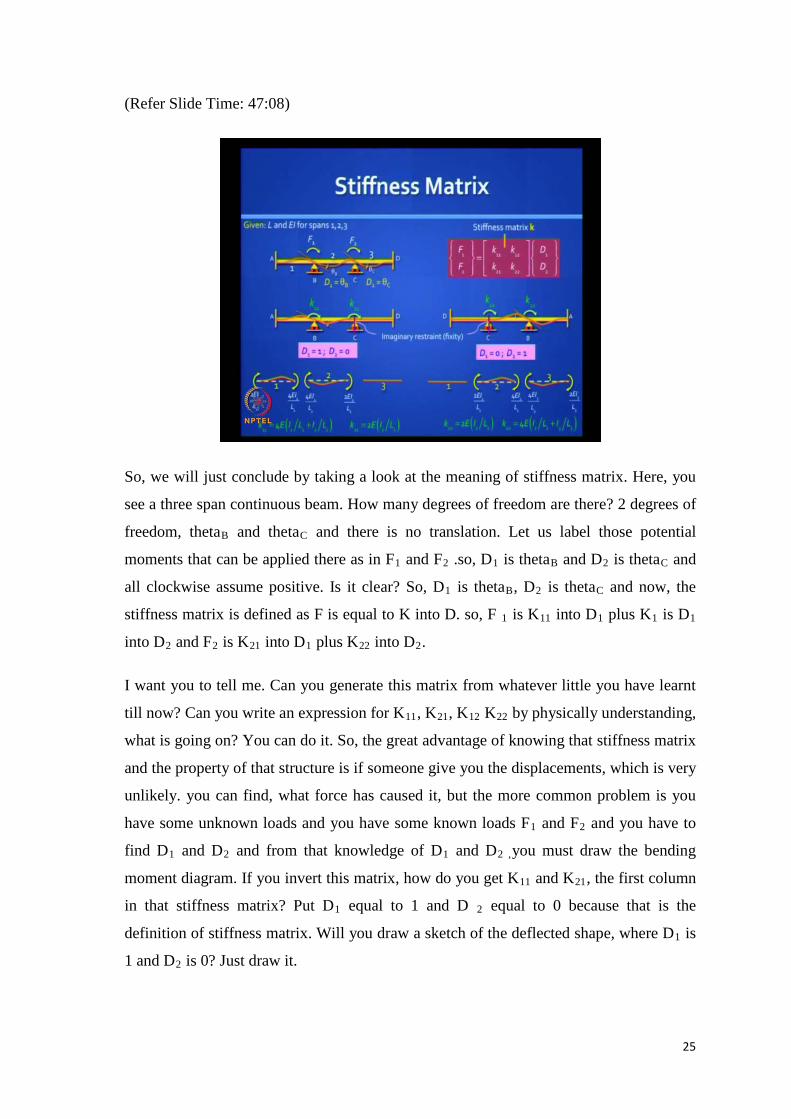
So, we will just conclude by taking a look at the meaning of stiffness matrix. Here, you
see a three span continuous beam. How many degrees of freedom are there? 2 degrees of
freedom, thetaB and thetaC and there is no translation. Let us label those potential
moments that can be applied there as in F1 and F2 .so, D1 is thetaB and D2 is thetaC and
all clockwise assume positive. Is it clear? So, D1 is thetaB, D2 is thetaC and now, the
stiffness matrix is defined as F is equal to K into D. so, F 1 is K11 into D1 plus K1 is D1
into D2 and F2 is K21 into D1 plus K22 into D2.
I want you to tell me. Can you generate this matrix from whatever little you have learnt
till now? Can you write an expression for K11, K21, K12 K22 by physically understanding,
what is going on? You can do it. So, the great advantage of knowing that stiffness matrix
and the property of that structure is if someone give you the displacements, which is very
unlikely. you can find, what force has caused it, but the more common problem is you
have some unknown loads and you have some known loads F1 and F2 and you have to
find D1 and D2 and from that knowledge of D1 and D2 ,you must draw the bending
moment diagram. If you invert this matrix, how do you get K11 and K21, the first column
in that stiffness matrix? Put D1 equal to 1 and D 2 equal to 0 because that is the
definition of stiffness matrix. Will you draw a sketch of the deflected shape, where D1 is
1 and D2 is 0? Just draw it.
26
Will it not look like this? (Refer Slide Time: 49:06) D1 is 1 and D2 is 0. Can you draw
the bending moment diagram for this? Even if you do not draw it, can you write in
expression for K11 straight away? K11 will be the external moment, you should have
applied there to get the shape. So, it will be the sum of the movements, you get at B A
and B C. (Refer Slide Time: 49:34) What you get in B A? 4 EI by L of that element 1.
What do you get, plus what? ((noise)) No, you are arresting. See, when you say D2 is 0,
someone is holding it at C and preventing that rotation. So, it will also be 4 EI.
If you take the other case, it will look like this. (Refer Slide Time: 50:00) you are now
allowing D2, but arresting D1. So, if you draw the free bodies, they will look this without
those forces and 4 EI by L and 4 EI by L for the second element with the carry over and
so do you agree K11 is 4 E into I1 by L1 plus 4 E into I2 by L2, very easy to do.
What is K21? K21 is what you get at the support, which you artificially fixed, F2. What
will it be? 2 E into I2 by L2. Similarly, you can do for the other case, you can see the
beautiful symmetry in K21 and K12, and that is how easy it is. So, it is not difficult, once
you are comfortable with the kinematic determinate structure. We will stop here and we
will continue tomorrow. Thank you.