Embed Size (px)
DESCRIPTION
Autodesk UniversityDesktop 2004-2005 Tips & Tricks
Citation preview
November 30 – December 3, 2004 ◊ Las Vegas, Nevada
How to Miss-USE and Abuse Autodesk® Architectural Desktop Jeanne Aarhus – ProSoft NET, Professional Software Solutions, Inc.
BD32-2 Learn how you can use Architectural Desktop objects for much more than their obvious use. Why does a wall have to be just a wall? Can a door be more than a door? Take advantage of all the capabilities Architectural Desktop has to offer. Discover the possibilities, then dazzle your co-workers back at the office. A sure-fire way to get a ticket to attend next year!
Who Should Attend: Intermediate and advanced Architectural Desktop users Topics Covered: * How to use Architectural Desktop objects and displays to solve everyday problems * Use Wall objects for more than walls * Use Doors for more than just doors * Use objects for innovative solutions * Learn how Architectural Desktop can help solve problems in unexpected ways
About the Speaker: Jeanne is known for keeping her training sessions fast-moving and fun. She is a nationally known speaker and expert in CAD and presents seminars and workshops on CAD productivity for managers and users in both corporate and college settings. She has been involved with production drawing, user support, standards coordination, programming, and training in CAD applications for more than 20 years. She continues to be actively involved in international, national, and local CAD user groups. [email protected]
How to Miss-USE and Abuse Autodesk® Architectural Desktop
How to Miss-USE and Abuse ADT What is this session about? This session will demonstrate how you can use ADT objects for much more than their obvious use. Why does a wall have to be just a wall? Can a door be more than a door? Do you take advantage of ALL the capabilities ADT has to offer? If you use ADT objects ONLY for the obvious…you are missing out! Attend this session to discover the possibilities; and then go home and “dazzle” your co-workers. A sure fire way to get a ticket to attend next year!
The topics I selected for this presentation were collected from friends, co-workers, other user groups; and of course the newsgroups.
If you have an idea or a great tip to pass along….I invite you to share your ideas with other users. This only works when we ALL share ideas and concepts. Keep the information flowing….and thanks to all those who helped with this collection of ideas.
About this document:
Topic available in Architectural Desktop 3.3 (although not as easily in most cases)
Topic available in Architectural Desktop 2004
Topic available in Architectural Desktop 2005
Object Type to “Abuse” Form of Abuse? (CREDIT – after all I didn’t think of all of these ideas on my own!)
Thanks to everyone who contributed ideas to this session. And remember me if you have a clever way to use ADT, send me YOUR ideas. We all learn through sharing!
1
How to Miss-USE and Abuse Autodesk® Architectural Desktop
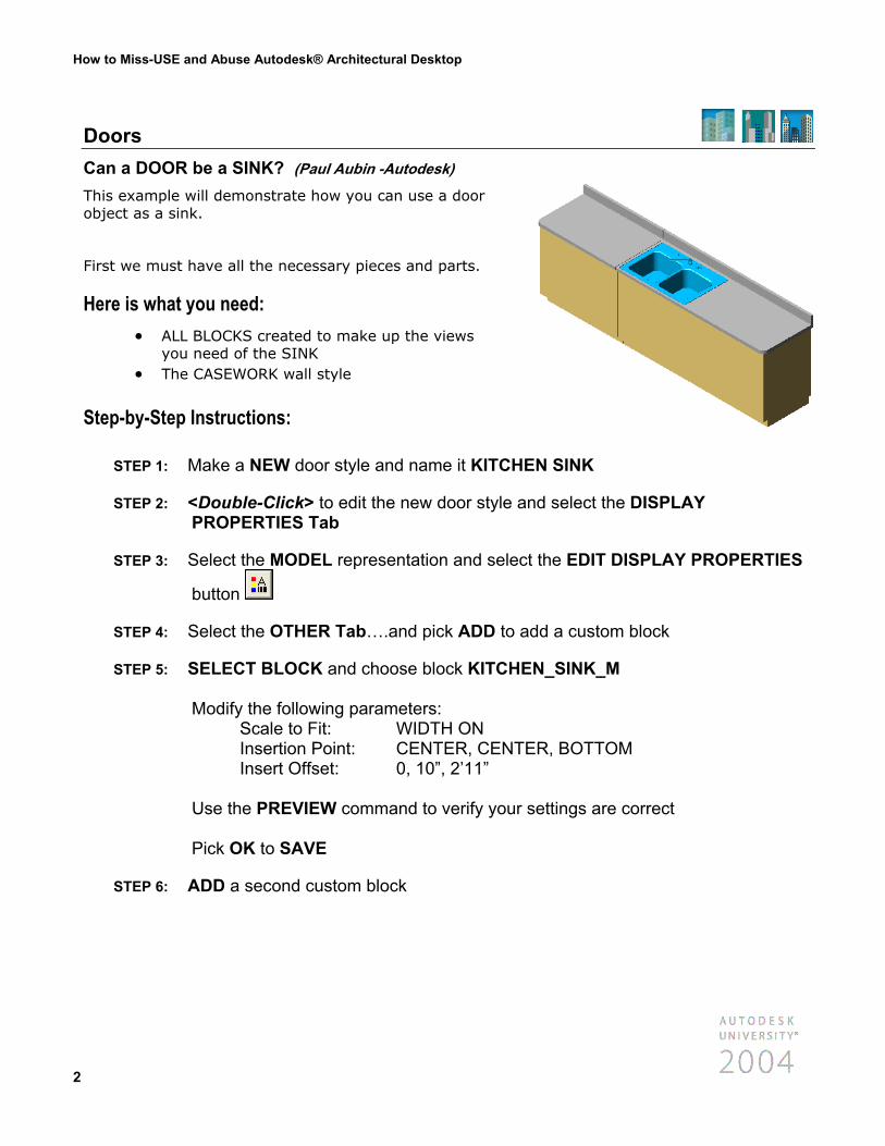
Doors Can a DOOR be a SINK? (Paul Aubin -Autodesk)
This example will demonstrate how you can use a door object as a sink.
First we must have all the necessary pieces and parts.
Here is what you need: • ALL BLOCKS created to make up the views
you need of the SINK • The CASEWORK wall style
Step-by-Step Instructions:
STEP 1: Make a NEW door style and name it KITCH
STEP 2: <Double-Click> to edit the new door style aPROPERTIES Tab
STEP 3: Select the MODEL representation and selec
button
STEP 4: Select the OTHER Tab….and pick ADD to
STEP 5: SELECT BLOCK and choose block KITCH Modify the following parameters: Scale to Fit: WIDTH ON Insertion Point: CENTER, CENT Insert Offset: 0, 10”, 2’11” Use the PREVIEW command to verify your Pick OK to SAVE
STEP 6: ADD a second custom block
2
EN SINK
nd select the DISPLAY
t the EDIT DISPLAY PROPERTIES
add a custom block
EN_SINK_M
ER, BOTTOM
settings are correct
How to Miss-USE and Abuse Autodesk® Architectural Desktop
STEP 7: SELECT BLOCK and choose block KITCHEN_SINK_BASE_M Modify the following parameters: Scale to Fit: WIDTH ON Insertion Point: CENTER, CENTER, BOTTOM Insert Offset: 0, 10”, 2’11 3/4”
STEP 8: ADD a third custom block
STEP 9: SELECT BLOCK and choose block KITCHEN_SINK_COUNTER_M Modify the following parameters: Scale to Fit: WIDTH ON Insertion Point: CENTER, CENTER, BOTTOM Insert Offset: 0, 10”, 2’11 3/4”
STEP 10: Before we place this “door” we need to turn off some of the default door displays. Select the LAYER/COLOR/LINETYPE Tab TURN OFF the visibility of the following door components: Door Panel Frame Stop Swing Glass
STEP 11: Use the ADD DOOR command to place the SINK into a CASEWORK wall
Now lets check out the FRONT View:
STEP 1: Select the KITCHEN SINK in the FRONT view and <Right-Click> to access the EDIT DOOR STYLE command
STEP 2: Select the ELEVATION representation and select the EDIT DISPLAY
PROPERTIES button
STEP 3: Select the OTHER Tab….and pick ADD to add a custom block
3
How to Miss-USE and Abuse Autodesk® Architectural Desktop
STEP 4: SELECT BLOCK and choose block KITCHEN_SINK_F Modify the following parameters: Insertion Point: CENTER, CENTER, BOTTOM Insert Offset: 0, 10”, 2’11 3/4” Scale to Fit: WIDTH ON
STEP 5: ADD a second custom block
STEP 6: SELECT BLOCK and choose block KITCHEN_SINK_BASE_F Modify the following parameters: Insertion Point: CENTER, CENTER, BOTTOM Insert Offset: 0, 0, 0 Scale to Fit: WIDTH ON
STEP 7: Select the LAYER/COLOR/LINETYPE Tab TURN OFF the visibility of the following door components: Door Panel Frame Stop Swing Glass
You can continue to edit each view as needed the same way until you have EXACTLY the look you want!
4
How to Miss-USE and Abuse Autodesk® Architectural Desktop
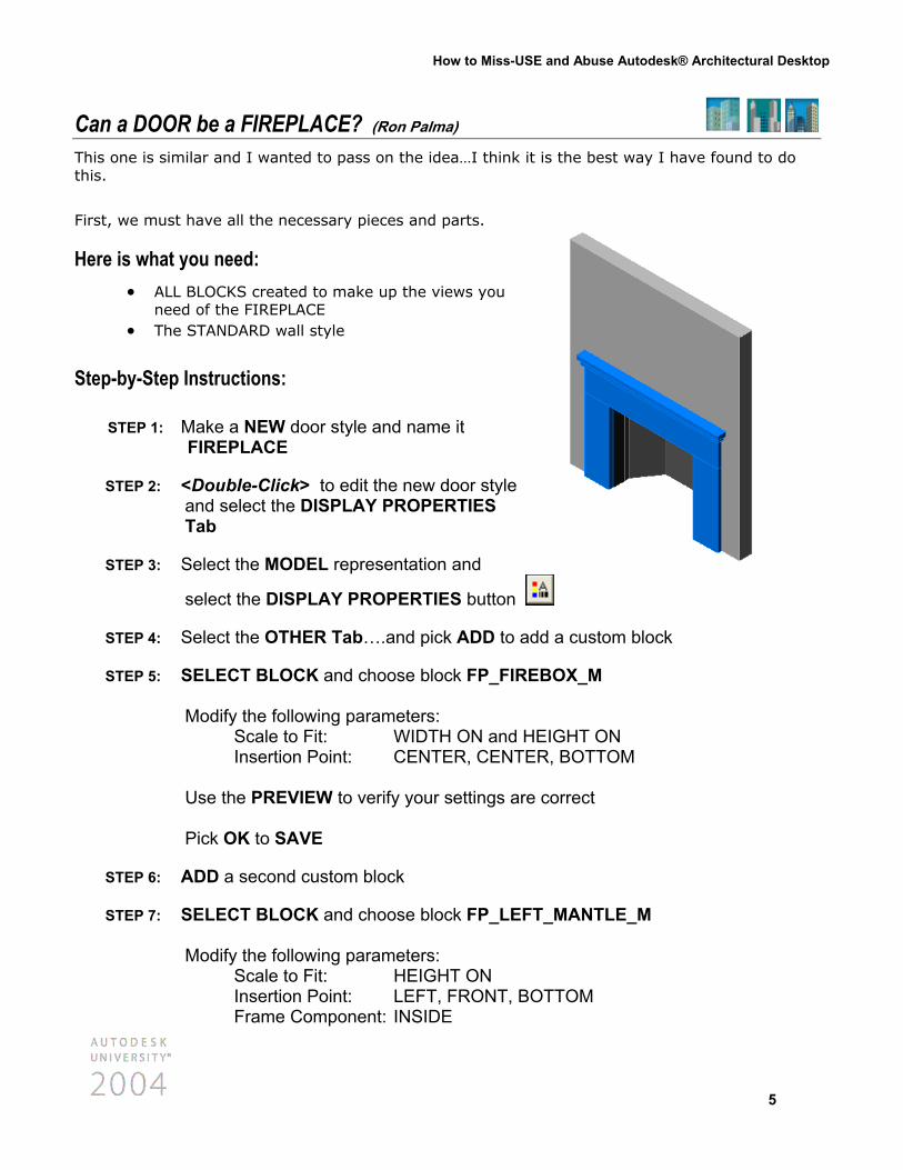
Can a DOOR be a FIREPLACE? (Ron Palma) This one is similar and I wanted to pass on the idea…I think it is the best way I have found to do this.
First, we must have all the necessary pieces and parts.
Here is what you need: • ALL BLOCKS created to make up the views you
need of the FIREPLACE • The STANDARD wall style
Step-by-Step Instructions:
STEP 1: Make a NEW door style and name it FIREPLACE
STEP 2: <Double-Click> to edit the new door style and select the DISPLAY PROPERTIES Tab
STEP 3: Select the MODEL representation and
select the DISPLAY PROPERTIES button
STEP 4: Select the OTHER Tab….and pick ADD to ad
STEP 5: SELECT BLOCK and choose block FP_FIRE Modify the following parameters: Scale to Fit: WIDTH ON and H Insertion Point: CENTER, CENTE Use the PREVIEW to verify your settings are Pick OK to SAVE
STEP 6: ADD a second custom block
STEP 7: SELECT BLOCK and choose block FP_LEFT Modify the following parameters: Scale to Fit: HEIGHT ON Insertion Point: LEFT, FRONT, BO Frame Component: INSIDE
d a custom block
BOX_M
EIGHT ON R, BOTTOM
correct
_MANTLE_M
TTOM
5
How to Miss-USE and Abuse Autodesk® Architectural Desktop
STEP 8: ADD a third custom block
STEP 9: SELECT BLOCK and choose block FP_RIGHT_MANTLE_M Modify the following parameters: Scale to Fit: HEIGHT ON Insertion Point: RIGHT, FRONT, BOTTOM Frame Component: INSIDE
STEP 10: SELECT BLOCK and choose block FP_TOP_MANTLE_M Modify the following parameters: Insertion Point: CENTER, FRONT, TOP Frame Component: INSIDE
STEP 11: Before we place this “door” we need to turn off some of the default door displays. Select the LAYER/COLOR/LINETYPE Tab TURN OFF the visibility of the following door components: Door Panel Stop Swing Glass
STEP 12: Use the ADD DOOR command to place the FIREPLACE into the existing wall
Now let’s check out the PLAN View
STEP 1: Select the FIREPLACE in the PLAN view and <Right-Click> to access the EDIT DOOR STYLE command
STEP 2: Select the PLAN representation and select the EDIT DISPLAY PROPERTIES
button
STEP 3: Select the OTHER Tab….and pick ADD to add a custom block
6
How to Miss-USE and Abuse Autodesk® Architectural Desktop
STEP 4: SELECT BLOCK and choose block FP_FIREBOX_P Modify the following parameters: Insertion Point: CENTER, CENTER, BOTTOM
STEP 5: Select the LAYER/COLOR/LINETYPE Tab TURN OFF the visibility of the following door components: Door Panel Frame Stop Swing Glass
You can continue to edit each view as needed the same way until you have EXACTLY the look you want!
• To really get the true benefit of this method….modify the HEIGHT and WIDTH of the “door” aka “fireplace”
STEP 1: Select the FIREPLACE and <Right-Click> to access the PROPERTIES command
STEP 2: Modify the height of the door to 4’ and the width to 3’6”. How’s that for performance!
7
How to Miss-USE and Abuse Autodesk® Architectural Desktop
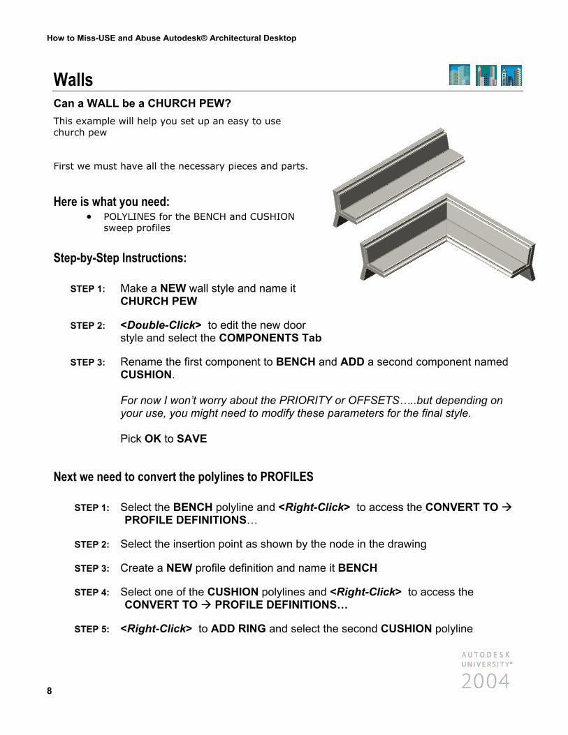
Walls Can a WALL be a CHURCH PEW? This example will help you set up an easy to use church pew
First we must have all the necessary pieces and parts.
Here is what you need: • POLYLINES for the BENCH and CUSHION
sweep profiles
Step-by-Step Instructions:
STEP 1: Make a NEW wall style and name it CHURCH PEW
STEP 2: <Double-Click> to edit the new door style and select the COMPONENTS Tab
STEP 3: Rename the first component to BENCH aCUSHION. For now I won’t worry about the PRIORITyour use, you might need to modify these Pick OK to SAVE
Next we need to convert the polylines to PROFILES
STEP 1: Select the BENCH polyline and <Right-CPROFILE DEFINITIONS…
STEP 2: Select the insertion point as shown by the
STEP 3: Create a NEW profile definition and name
STEP 4: Select one of the CUSHION polylines anCONVERT TO PROFILE DEFINITIO
STEP 5: <Right-Click> to ADD RING and select
8
nd ADD a second component named
Y or OFFSETS…..but depending on parameters for the final style.
lick> to access the CONVERT TO
node in the drawing
it BENCH
d <Right-Click> to access the NS…
the second CUSHION polyline
How to Miss-USE and Abuse Autodesk® Architectural Desktop
STEP 6: Select the insertion point as shown by the node in the drawing
STEP 7: Create a NEW profile definition and name it CUSHION
Now we need to add these sweeps to the wall style CHURCH PEW
STEP 1: Draw a wall using the wall style CHURCH PEW
STEP 2: Select the new “wall” and <Right-Click> to access the SWEEP ADD…command
STEP 3: Select the wall component BENCH and the profile definition BENCH Pick OK to SAVE
STEP 4: Select the new “wall” again and <Right-Click> to access the SWEEP ADD…
STEP 5: Select the wall component CUSHION and the profile definition CUSHION…. Pick OK to SAVE
Now let’s change the color of the cushions:
STEP 1: Select the wall CHURCH PEW and <Right-Click> to access the EDIT WALL STYLE command….and select the MATERIALS Tab
STEP 2: Select the BENCH component and select the EDIT MATERIAL button
STEP 3: Select the GENERAL HIGH DETAIL display representation and pick the STYLE OVERRIDE checkbox.
STEP 4: Select the OTHER Tab and change the RENDER MATERIAL to WOOD.WHITE.ASH
STEP 5: Pick OK to SAVE.
STEP 6: Modify BOTH materials as needed.
9
How to Miss-USE and Abuse Autodesk® Architectural Desktop
•
• •
If you want to draw another CHURCH PEW wall….it won’t look like this unless you use this wall as the selected object. Try it this way instead.
STEP 1: Select the existing CHURCH PEW wall and <Right-Click> to access the
ADD SELECTED command
STEP 2: Now you can draw a CHURCH PEW without having to “sweep” the wall style again.
If you draw a corner wall you might need to run the SWEEP MITRE command to clean up the corners. But it still works great!
You might need to change the CUT PLANE in PLAN VIEW for the desired appearance. Try turning on DISPLAY INNER LINES BELOW and setting a manual cut plane at 1’-4” and 3’-6”. Does that look better!
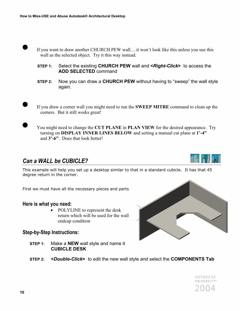
Can a WALL be CUBICLE? This example will help you set up a desktop similar to that in a standard cubicle. It has that 45 degree return in the corner.
First we must have all the necessary pieces and parts
Here is what you need: POLYLINE to represent the desk return which will be used for the wall endcap condition
•
Step-by-Step Instructions:
STEP 1: Make a NEW wall style and name it
CUBICLE DESK
STEP 2: <Double-Click> to edit the new wall sty
10
le and select the COMPONENTS Tab
How to Miss-USE and Abuse Autodesk® Architectural Desktop
STEP 3: Rename the first component to CUBICLE DESK Modify the following parameters: Priority: 2 Width: 2’0” Bottom Elevation: 2’6 from WALL BOTTOM Top Elevation: 2’8” from WALL BOTTOM Pick OK to SAVE
Now we need to add the ENDCAP condition to the CUBICLE DESK wall
STEP 1: Draw a wall using the new style CUBICLE DESK
STEP 2: Select the new “wall” and <Right-Click> to access the ENDCAPS CALCULATE AUTOMATICALLY
STEP 3: Select the polyline and answer NO to delete the polyline…until you know this is what you want
STEP 4: <Right-Click> and select WALLSTYLEDEFAULT…and give the ENDCAP STYLE the name CUBICLE DESK RETURN Pick OK to SAVE
How does that work? Pretty good right?
• If you want to have the return on just one end you can just use the OVERRIDE PROPERTIES to modify the specific wall end as needed.
STEP 1: Select the wall and <Right-Click> to access the ENDCAPS OVERRIDE ENDCAP STYLE and set either end of the wall back to the STANDARD endcap style.
11
How to Miss-USE and Abuse Autodesk® Architectural Desktop
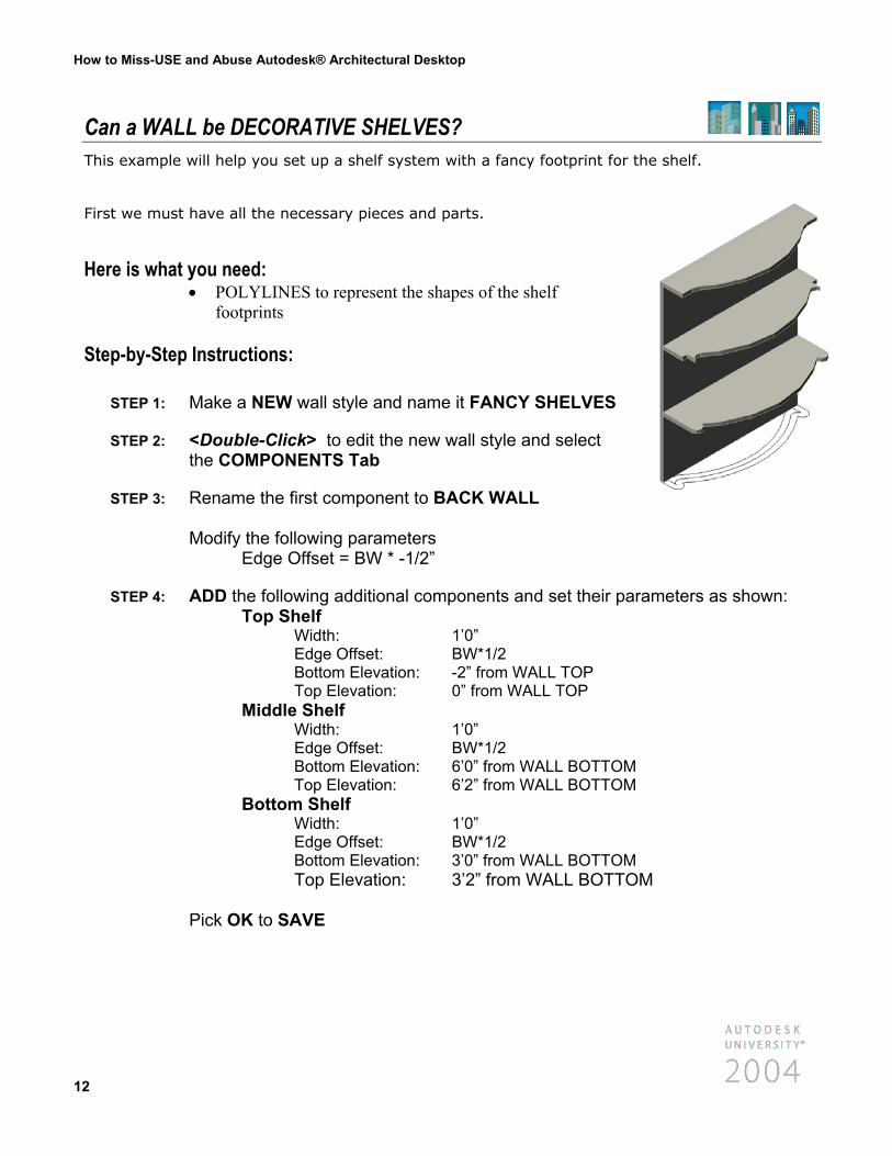
Can a WALL be DECORATIVE SHELVES? This example will help you set up a shelf system with a fancy footprint for the shelf.
First we must have all the necessary pieces and parts.
Here is what you need: POLYLINES to represent the shapes of the shelf footprints
•
Step-by-Step Instructions:
STEP 1: Make a NEW wall style and name it FANCY SHELVES
STEP 2: <Double-Click> to edit the new wall style and select the COMPONENTS Tab
STEP 3: Rename the first component to BACK WALL Modify the following parameters Edge Offset = BW * -1/2”
STEP 4: ADD the following additional components and set their par Top Shelf Width: 1’0” Edge Offset: BW*1/2 Bottom Elevation: -2” from WALL TOP Top Elevation: 0” from WALL TOP Middle Shelf Width: 1’0” Edge Offset: BW*1/2 Bottom Elevation: 6’0” from WALL BOTTOM Top Elevation: 6’2” from WALL BOTTOM Bottom Shelf Width: 1’0” Edge Offset: BW*1/2 Bottom Elevation: 3’0” from WALL BOTTOM Top Elevation: 3’2” from WALL BOTTO Pick OK to SAVE
12
ameters as shown:
M
How to Miss-USE and Abuse Autodesk® Architectural Desktop
Next, we need to convert the polyline to WALL MODIFIERS
STEP 1: Select the WALL and <Right-Click> to access the PLAN MODIFIERS CONVERT POLYLINE TO WALL MODIFIER…command
STEP 2: Select the first polyline for the bottom shelf and answer NO to deleting it. Give this modifier the name BOTTOM SHELF
STEP 3: Select the BOTTOM SHELF wall component and set START ELEVATION to 3’0 from BOTTOM END ELEVATION to 3’2 from BOTTOM
STEP 4: Repeat for the MIDDLE SHELF wall component and set START ELEVATION to 6’0 from BOTTOM END ELEVATION to 6’2 from BOTTOM
STEP 5: Repeat for the TOP SHELF wall component and set START ELEVATION to -2” from TOP END ELEVATION to 0 from TOP
YES…you CAN see through WALLS… Get a “CLEAR” view through walls and windows. Use the trick to see through objects to get a clear view of your building. Try it out on roofs too!
STEP 1: Select a WALL and <Right-Click> to access the EDIT WALL STYLE command
STEP 2: Select the DISPLAY PROPERTIES Tab
STEP 3: Select the MODEL representation and select the EDIT DISPLAY PROPERTIES
button
STEP 4: TURN OFF the BY MATERIAL option for BOUNDARY 1 and modify the color to COLOR 123 Pick OK to SAVE all the changes.
STEP 5: Select a ROOF and <Right-Click> to access the EDIT OBJECT DISPLAY command
STEP 6: Select the DISPLAY PROPERTIES Tab
13
How to Miss-USE and Abuse Autodesk® Architectural Desktop
STEP 7: Select the MODEL representation and select the EDIT DISPLAY PROPERTIES
button
STEP 8: TURN OFF the BY MATERIAL option for ROOF and modify the color to COLOR 43 Pick OK to SAVE all the changes.
STEP 9: Key-in the RMAT command and IMPORT the following materials: AQUA GLAZE GREEN GLASS
STEP 10: Assign the following materials to these specific colors: AQUA GLAZE to COLOR 123 GREEN GLASS to COLOR 43
STEP 11: SHADE the model view to see the “clear walls”
You can also use materials to obtain the “translucent” wall effect, however, I prefer to leave the wall materials for later use in the project and use the render materials for the “working translucent” effect. But you decide which works best for you!
14
How to Miss-USE and Abuse Autodesk® Architectural Desktop
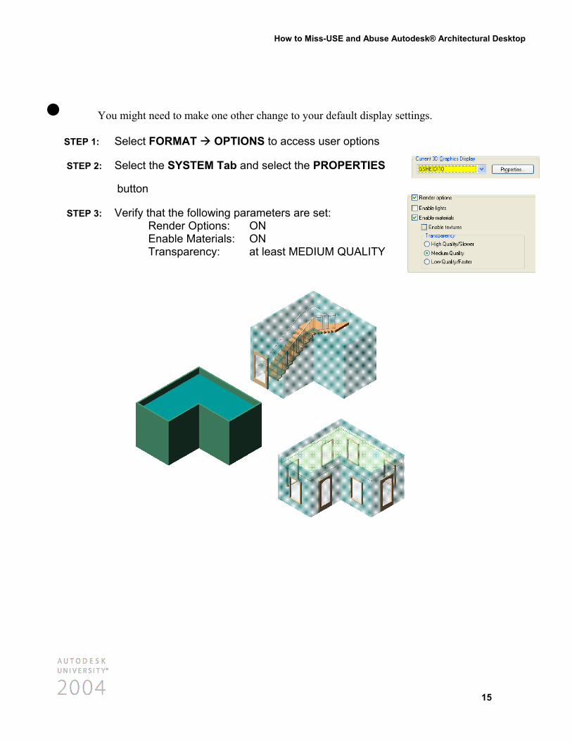
• You might need to make one other change to your default display settings. STEP 1: Select FORMAT OPTIONS to access user options
STEP 2: Select the SYSTEM Tab and select the PROPERTIES
button
STEP 3: Verify that the following parameters are set: Render Options: ON Enable Materials: ON Transparency: at least MEDIUM QUALITY
15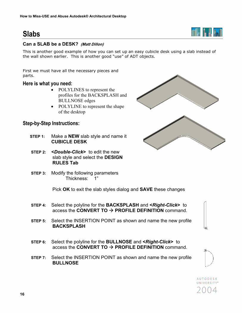
How to Miss-USE and Abuse Autodesk® Architectural Desktop
Slabs Can a SLAB be a DESK? (Matt Dillon)
This is another good example of how you can set up an easy cubicle desk using a slab instead of the wall shown earlier. This is another good “use” of ADT objects.
First we must have all the necessary pieces and parts.
Here is what you need: POLYLINES to represent the profiles for the BACKSPLASH and BULLNOSE edges
•
• POLYLINE to represent the shape of the desktop
Step-by-Step Instructions:
STEP 1: Make a NEW slab style and name it CUBICLE DESK
STEP 2: <Double-Click> to edit the new slab style and select the DESIGN RULES Tab
STEP 3: Modify the following parameters Thickness: 1” Pick OK to exit the slab styles dialog and SAVE these changes
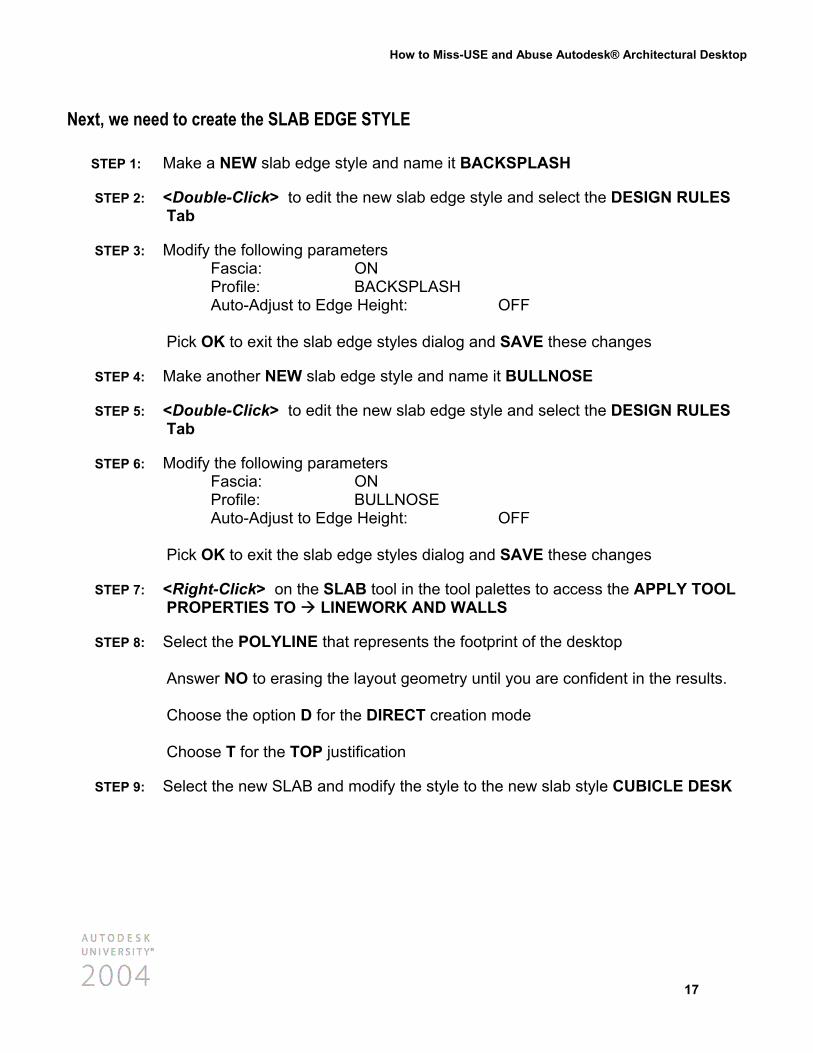
STEP 4: Select the polyline for the BACKSPLASH and <Right-Click> to access the CONVERT TO PROFILE DEFINITION command.
STEP 5: Select the INSERTION POINT as shown and name the new profile BACKSPLASH
STEP 6: Select the polyline for the BULLNOSE and <Right-Click> to access the CONVERT TO PROFILE DEFINITION command.
STEP 7: Select the INSERTION POINT as shown and name the new profile BULLNOSE
16
How to Miss-USE and Abuse Autodesk® Architectural Desktop
Next, we need to create the SLAB EDGE STYLE
STEP 1: Make a NEW slab edge style and name it BACKSPLASH
STEP 2: <Double-Click> to edit the new slab edge style and select the DESIGN RULES Tab
STEP 3: Modify the following parameters Fascia: ON Profile: BACKSPLASH Auto-Adjust to Edge Height: OFF Pick OK to exit the slab edge styles dialog and SAVE these changes
STEP 4: Make another NEW slab edge style and name it BULLNOSE
STEP 5: <Double-Click> to edit the new slab edge style and select the DESIGN RULES Tab
STEP 6: Modify the following parameters Fascia: ON Profile: BULLNOSE Auto-Adjust to Edge Height: OFF Pick OK to exit the slab edge styles dialog and SAVE these changes
STEP 7: <Right-Click> on the SLAB tool in the tool palettes to access the APPLY TOOL PROPERTIES TO LINEWORK AND WALLS
STEP 8: Select the POLYLINE that represents the footprint of the desktop Answer NO to erasing the layout geometry until you are confident in the results. Choose the option D for the DIRECT creation mode Choose T for the TOP justification
STEP 9: Select the new SLAB and modify the style to the new slab style CUBICLE DESK
17
How to Miss-USE and Abuse Autodesk® Architectural Desktop
Next we need to modify the appropriate slab edges to our new slab edge styles
STEP 1: Select the new slab and <Right-Click> to access the EDIT SLAB EDGES… command
STEP 2: Select both of the back edges and modify the following parameters: Edge Style: BACKSPLASH
STEP 3: Select all of the front edges and modify the following parameters: Edge Style: BULLNOSE
Your desk should now be complete. What do you think of this method?
18
How to Miss-USE and Abuse Autodesk® Architectural Desktop
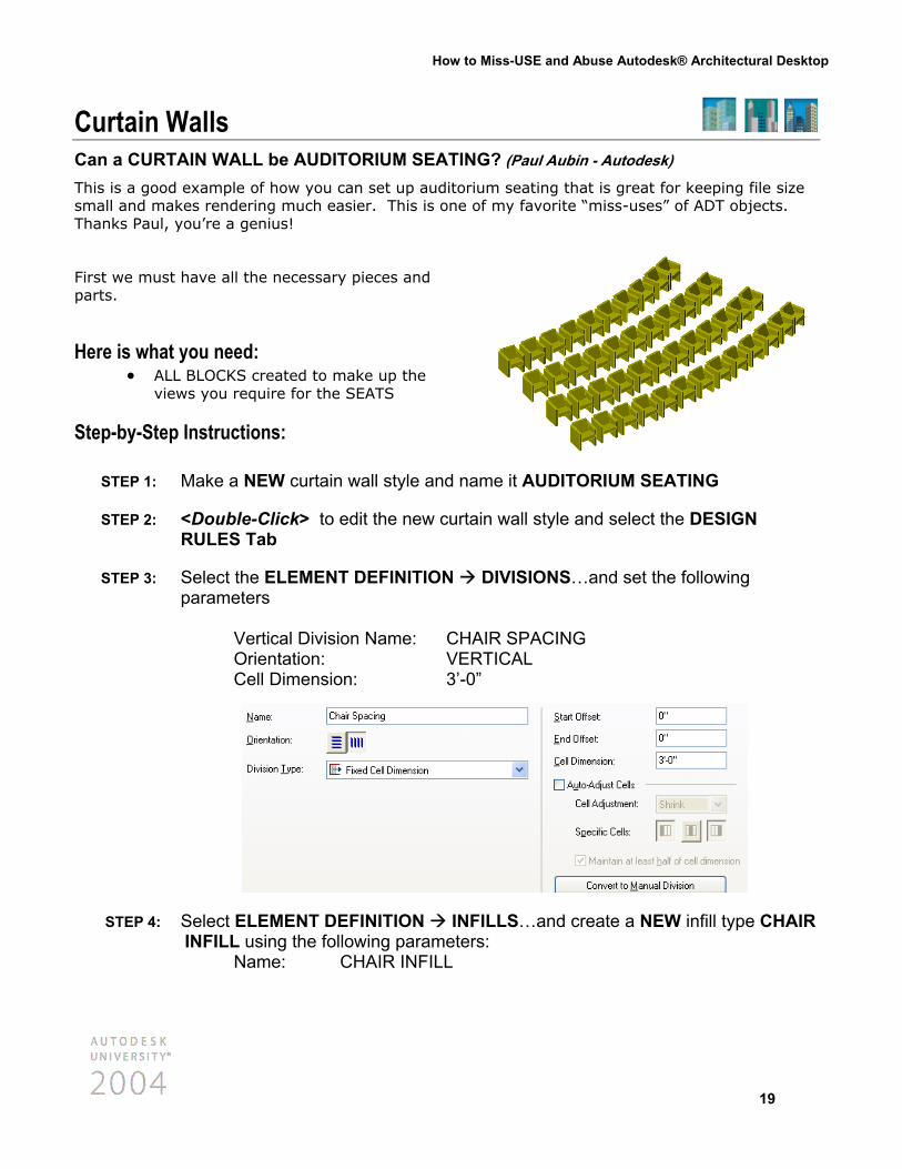
Curtain Walls Can a CURTAIN WALL be AUDITORIUM SEATING? (Paul Aubin - Autodesk)
This is a good example of how you can set up auditorium seating that is great for keeping file size small and makes rendering much easier. This is one of my favorite “miss-uses” of ADT objects. Thanks Paul, you’re a genius!
First we must have all the necessary pieces and parts.
Here is what you need: • ALL BLOCKS created to make up the
views you require for the SEATS
Step-by-Step Instructions:
STEP 1: Make a NEW curtain wall style and nam
STEP 2: <Double-Click> to edit the new curtainRULES Tab
STEP 3: Select the ELEMENT DEFINITION Dparameters Vertical Division Name: CHAI Orientation: VERT Cell Dimension: 3’-0”
STEP 4: Select ELEMENT DEFINITION INFIINFILL using the following parameters Name: CHAIR INFILL
e it AUDITORIUM SEATING
wall style and select the DESIGN
IVISIONS…and set the following
R SPACING ICAL
LLS…and create a NEW infill type CHAIR :
19
How to Miss-USE and Abuse Autodesk® Architectural Desktop
STEP 5: Select PRIMARY GRID and set the following parameters: Division Assignment: CHAIR SPACING Cell Assignment: CHAIR INFILL Frame Assignment: DEFAULT FRAME Mullion Assignment: DEFAULT MULLION
STEP 6: Select the DISPLAY PROPERTIES Tab
STEP 7: Select the MODEL representation and select the EDIT DISPLAY PROPERTIES
button
STEP 8: Select the OTHER Tab….and pick the ADD button to add a custom block
STEP 9: Modify the following parameters: Component Type: INFILL Component Name: CHAIR INFILL (use the SELECT ELEMENT button) Draw Custom Graphics: ON Replace Graphics: ON Select Block: SEATING_M Insertion Point: CENTER, FRONT, BOTTOM Pick OK to SAVE these changes
STEP 10: Before we place this “curtain wall” we need to turn off some of the default curtain wall displays. Select the LAYER/COLOR/LINETYPE Tab TURN OFF the visibility of the following curtain wall components: Default Frame Default Mullion
STEP 11: Pick OK and SAVE all changes
STEP 12: Use the ADD CURTAIN WALL command to place the AUDITORIUM SEATING in your drawing. Try using STRAIGHT are ARC curtain walls. This one works GREAT doesn’t it!!!!!
20
How to Miss-USE and Abuse Autodesk® Architectural Desktop
Now let’s check out the PLAN View
STEP 1: Select the AUDITORIUM SEATING in the PLAN view and <Right-Click> to access the EDIT CURTAIN WALL STYLE command
STEP 2: Select the PLAN representation and select the EDIT DISPLAY PROPERTIES
button
STEP 3: Select the CUSTOM PLAN COMPONENTS Tab….and pick ADD to add a custom block
STEP 4: Modify the following parameters: Component Type: INFILL Component Name: CHAIR INFILL (use the SELECT ELEMENT button) Draw Custom Graphics: ON Replace Graphics: ON Select Block: SEATING_P Insertion Point: CENTER, FRONT
You can continue to edit each view as needed the same way until you have EXACTLY the look you want!
• Use the OFFSET command to create as many rows of seating as needed.
21
How to Miss-USE and Abuse Autodesk® Architectural Desktop
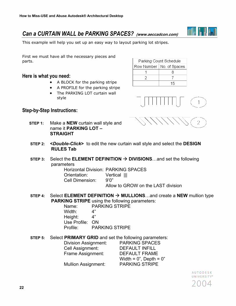
Can a CURTAIN WALL be PARKING SPACES? (www.aeccadcon.com) This example will help you set up an easy way to layout parking lot stripes.
First we must have all the necessary pieces and parts.
Here is what you need: • • •
A BLOCK for the parking stripe A PROFILE for the parking stripe The PARKING LOT curtain wall style
Step-by-Step Instructions:
STEP 1: Make a NEW curtain wall style and name it PARKING LOT – STRAIGHT
STEP 2: <Double-Click> to edit the new curtaRULES Tab
STEP 3: Select the ELEMENT DEFINITION parameters Horizontal Division: PARKING Orientation: Vertical ||| Cell Dimension: 9’0” Allow to GR
STEP 4: Select ELEMENT DEFINITION MUPARKING STRIPE using the followin Name: PARKING STRIP Width: 4” Height: 4” Use Profile: ON Profile: PARKING STRIP
STEP 5: Select PRIMARY GRID and set the fo Division Assignment: PAR Cell Assignment: DEF Frame Assignment: DEF Wid Mullion Assignment: PAR
22
in wall style and select the DESIGN
DIVISIONS…and set the following
SPACES
OW on the LAST division
LLIONS…and create a NEW mullion type g parameters: E
E
llowing parameters: KING SPACES AULT INFILL AULT FRAME th = 0”, Depth = 0” KING STRIPE
How to Miss-USE and Abuse Autodesk® Architectural Desktop
STEP 6: Select the DISPLAY PROPERTIES Tab
STEP 7: Select the MODEL representation and select the EDIT DISPLAY PROPERTIES
button
STEP 8: Select the OTHER Tab….and pick ADD to add a custom block and set the following parameters: Component Type: MULLION Component Name: PARKING STRIPE Draw Custom Graphics: ON Replace Graphics: ON Select Block: PARKING STRIPE Insertion Point: CENTER, FRONT, BOTTOM
STEP 9: Before we place this “curtain wall” we need to turn off some of the default curtain wall displays. Select the LAYER/COLOR/LINETYPE Tab TURN OFF the visibility of the following curtain wall components: Default Infill Default Frame Default Mullion
STEP 10: Use the ADD CURTAIN WALL command to place the PARKING STRIPES onto your parking lot layout
Now let’s check out the PLAN View
STEP 1: Select the PARKING STRIPES in the PLAN view and <Right-Click> to access the EDIT CURTAIN WALL STYLE command
STEP 2: Select the PLAN representation and select the EDIT DISPLAY PROPERTIES
button
STEP 3: Before we place this “curtain wall” we need to turn off some of the default curtain wall displays. Select the LAYER/COLOR/LINETYPE Tab TURN OFF the visibility of the following curtain wall components: Default Infill Default Frame
23
How to Miss-USE and Abuse Autodesk® Architectural Desktop
STEP 4: Before we place this “curtain wall” we need to turn off some of the default curtain wall displays. Select the LAYER/COLOR/LINETYPE Tab TURN OFF the visibility of the following curtain wall components: Default Infill Default Frame Default Mullion
You can continue to edit each view as needed the same way until you have EXACTLY the look you want!
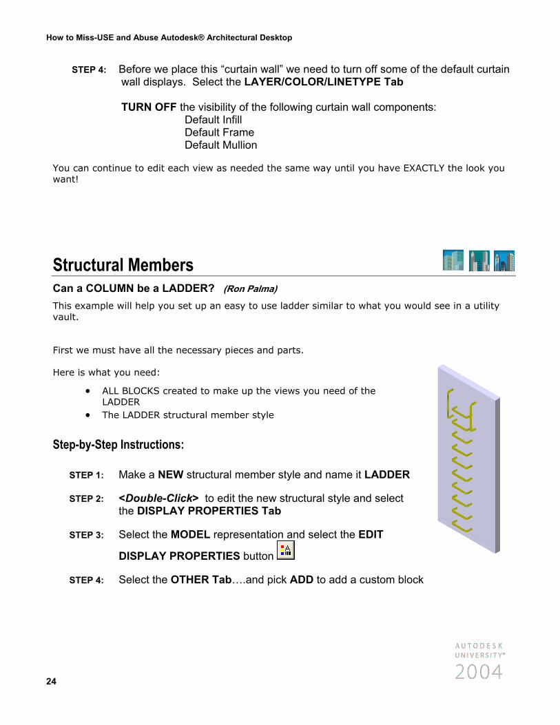
Structural Members Can a COLUMN be a LADDER? (Ron Palma) This example will help you set up an easy to use ladder similar to what you would see in a utility vault.
First we must have all the necessary pieces and parts. Here is what you need:
• ALL BLOCKS created to make up the views you need of the LADDER
• The LADDER structural member style
Step-by-Step Instructions:
STEP 1: Make a NEW structural member style and name it LADDER
STEP 2: <Double-Click> to edit the new structural style and select the DISPLAY PROPERTIES Tab
STEP 3: Select the MODEL representation and select the EDIT
DISPLAY PROPERTIES button
STEP 4: Select the OTHER Tab….and pick ADD to add a custom block
24
How to Miss-USE and Abuse Autodesk® Architectural Desktop
STEP 5: SELECT BLOCK and choose block HANDRAIL_M Modify the following parameters: Position Along (X): END OF CURVE Insertion Offset (X): -6” Pick OK to SAVE…you can use the PREVIEW button to check your work.
STEP 6: ADD a second custom block SELECT BLOCK and choose block RUNG_M Modify the following parameters: Repeat Mode: START OF CURVE Start Offset: 1’ End Offset: -1’ Space Between: 1’
STEP 7: Before we place this “column” we need to turn off some of the default structural displays
STEP 8: Select the LAYER/COLOR/LINETYPE Tab TURN OFF the visibility of ALL the default structural components
STEP 9: Use the ADD COLUMN command to place the LADDER next to the existing wall
STEP 10: Modify the HEIGHT of the column and note that additional rungs are added as needed.
Now let’s check out the PLAN View
STEP 1: Select the LADDER in the PLAN view and <Right-Click> to access the EDIT MEMBER STYLE command
STEP 2: Select the PLAN representation and select the EDIT DISPLAY PROPERTIES
button
STEP 3: Select the OTHER Tab….and pick ADD to add a custom block
25
How to Miss-USE and Abuse Autodesk® Architectural Desktop
STEP 4: SELECT BLOCK and choose block LADDER_P Modify the following parameters: Position Along (X): START OF CURVE Pick OK to SAVE…you can use the PREVIEW button to check your work.
Now let’s check out the LEFT SIDE View
STEP 1: Select the LADDER in the SIDE view and <Right-Click> to access the EDIT MEMBER STYLE command
STEP 2: Select the ELEVATION representation and select the EDIT DISPLAY
PROPERTIES button
STEP 3: Select the OTHER Tab….and pick ADD to add a custom block
STEP 4: SELECT BLOCK and choose block HANDRAIL_L Modify the following parameters: Position Along (X): END OF CURVE Insertion Offset (X): -1’ Pick OK to SAVE…you can use the PREVIEW button to check your work.
STEP 5: ADD a second custom block SELECT BLOCK and choose block RUNG_L Modify the following parameters: Repeat Mode: START OF CURVE Start Offset: 1’ End Offset: -1’ Space Between: 1’ Pick OK to SAVE…you can use the PREVIEW button to check your work.
WELL…..that's probably more than I have time for….but hopefully not more than you wanted to know! I hope this session has been a benefit to each of you….and have a GREAT CONFERENCE!
26
Thank you for your time……I hope I didn't talk too fast! Please forward any questions or suggestions to me via email at - [email protected]