Embed Size (px)
Citation preview
ADSL2/2+ Router
Copyright Statement
is the registered trademark of Shenzhen Tenda Technology Co., Ltd. All the products and product names mentioned herein are the trademarks or registered trademarks of their respective holders. Copyright of the whole product as integration, including its accessories and software, belongs to Shenzhen Tenda Technology Co., Ltd. Without prior expressed written permission from Shenzhen Tenda Technology Co., Ltd, any individual or party is not allowed to copy, plagiarize, reproduce, or translate it into other languages.
All photos and product specifications mentioned in this manual are for references only. Upgrades of software and hardware may occur; Tenda reserves the right to revise this publication and to make changes in the content hereof without obligation to notify any person or organization of such revisions or changes. If you would like to know more about our product information, please visit our website at www.tenda.cn
- 1 -
ADSL2/2+ Router
Table of Contents COPYRIGHT STATEMENT ............................................................. - 1 -
CHAPTER 1 PRODUCT OVERVIEW.............................................. - 5 -
1.2 PACKAGE CONTENTS.............................................................- 7 -
CHAPTER 2 HARDWARE OVERVIEW .......................................... - 8 -
2.1 FRONT PANEL ...........................................................................- 8 -
2.1 BACK PANEL OVERVIEW ...........................................................- 10 -
CHAPTER 3 QUICK SETUP FOR INTERNET CONNECTION..... - 12 -
3.1 CONFIG TCP/IP SETTINGS ON PC ............................................- 12 -
3.2 LOGGING ON TO WEB MANAGER USING THE SETUP WIZARD.........- 15 -
3.3 LOGGING ON TO WEB MANAGER VIA WEB BROWSER...................- 16 -
CHAPTER 4 ADVANCED SETTINGS........................................... - 26 -
4.1 STATUS...................................................................................- 27 -
4.1.1 General......................................................................... - 27 -
4.1.2 ADSL ......................................................................... - 28 -
4.1.3 LAN .............................................................................. - 28 -
4.1.4 WAN ............................................................................. - 29 -
4.1.5 Wireless........................................................................ - 29 -
4.1.6 ADSL Traffic Statistics................................................... - 30 -
4.2 QUICK SETUP..........................................................................- 30 -
4.3 NETWORK...............................................................................- 36 -
4.3.1 LAN .............................................................................. - 37 -
4.3.2 WAN Settings ............................................................... - 37 -
- 2 -
ADSL2/2+ Router
4.3.3 MAC Address Clone ..................................................... - 43 -
4.3.4 DHCP ........................................................................... - 44 -
4.3.4 ADSL Settings .............................................................. - 47 -
4.4 WIRELESS...............................................................................- 47 -
4.4.1. Basic Settings.............................................................. - 48 -
4.4.2 Security ........................................................................ - 52 -
4.4.3 MAC-based Wireless Access Control ........................... - 54 -
4.3.4 WDS ............................................................................. - 56 -
4.3.5 Connection Status ........................................................ - 59 -
4.5 ADVANCED APPLICATIONS.........................................................- 60 -
4.5.1 System Mode................................................................ - 60 -
4.5.2 IPTV ............................................................................. - 62 -
4.5.3 Bandwidth Control ........................................................ - 66 -
4.5.4 Connection List............................................................. - 67 -
4.5.5 DDNS ........................................................................... - 67 -
4.5.6 Virtual Server................................................................ - 69 -
4.5.7 DMZ Host ..................................................................... - 72 -
4.5.8 UPNP ........................................................................... - 73 -
4.6 SECURITY ...............................................................................- 74 -
4.6.1 MAC Address Filter....................................................... - 75 -
4.6.2 CLIENT FILTER....................................................................- 77 -
4.6.3 URL Filter ..................................................................... - 80 -
4.6.4 Remote Web-based Management................................ - 81 -
4.7 TOOLS....................................................................................- 83 -
4.7.1 Logs ........................................................................... - 83 -
4.7.2 Time ........................................................................... - 84 -
4.7.3 Change Password/User Name ..................................... - 85 -
4.7.4 Backup....................................................................... - 88 -
4.7.5 Restore ...................................................................... - 89 -
- 3 -
ADSL2/2+ Router
4.7.6 Firmware Upgrade........................................................ - 91 -
4.7.7 Restore to Factory Default Settings.............................. - 93 -
A PPENDIX 1................................................................................. - 94 -
1. CONFIG PC’S TCP/IP MANUALLY ................................................- 94 -
2. INITIATE A DIALUP ON PC.............................................................- 95 -
APPENDIX 2 ................................................................................. - 99 -
1. TROUBLESHOOTING ...................................................................- 99 -
2. VERIFY CONNECTIVITY BETWEEN THE DEVICE AND YOUR PC.......- 100 -
3. FAQS...................................................................................- 102 -
APPENDIX 3 EMC STATEMENT ................................................ - 106 -
CONTACT INFORMATION ...............................................................- 109 -
- 4 -
ADSL2/2+ Router
Chapter 1 Product Overview
Note: This user guide applies to Tenda wireless N ADSL2+ modem routers both W300D and W150D. W300D is used as an
example throughout this user guide for demonstration and explanation.
These two products differ in the following ascpects: the former is
equipped with 2 antennas and delivers up to 300Mbps wireless rate;
while the latter is equipped with 1 antenna and delivers up to 150Mbps
wireless rate. Functions and operations are subject to vary depending
on different software versions; please refer to the actual product you
purchase.
Thanks for purchasing this W300D/ W150D! It is an easy-to- install
gateway device with a user-friendly and most intuitive Web utility, letting
you config the device for Internet access in minutes. The product is an
all-in-one device that combines the function of an ADSL2+ Modem,
wireless router, wired router and switch, allowing you to connect to your
ISP using a telephone cable or an Ethernet cable. Based on 11n
technology while staying backward compatible with 11b/g devices, the
product offers a collection of advanced functionalities and features
including wireless security, IP/MAC filter guarding your network from
malicious attacks, IPTV that lets you enjoy videos on TV set while
surfing Internet, DHCP server that auto-configs your LAN PCs, virtual
server, DDNS that allows you to host web servers without worrying
about a changing IP address, remote web management that makes
managing the product anywhere from Internet a reality.
- 5 -
ADSL2/2+ Router
1.1 Features Web based easy-to-install utility allows quick and simple settings
for Internet connection
Complies with IEEE802.11b/g/n, IEEE802.3, IEEE802.3u, ADSL,
ADSL2, ADSL2+ standards etc
Connect to Internet through DSL line or Ethernet cable
Bridge, PPPoE, PPPoA, dynamic IP and static IP, Internet
connection types Combines the function of an ADSL2+ Modem, wireless router,
wired router and switch
Up to 24Mbps ADSL downstream rate and up to 1Mbps upstream
rate
Compatible with mainstream DSLAM equipments
Up to 300Mbps wireless rate, 6x faster than a common 54Mbps
product WPA and the latest WPA2
Auto-selects wireless channel
FDM to enable telephoning, faxing and surfing activities to
proceed simultaneously without mutual interference
Supports IPTV service
Backup current settings to local hard drive for future use
Setup wizard guides through the whole process of configuration
Lightning proof design up to 6000 voltage
Firewall to protect your network from malicious attacks
- 6 -
ADSL2/2+ Router
1.2 Package Contents
Unpack the package and check the following items. If any of the listed
items below is missing or damaged, contact your Tenda reseller for
immediate replacement.
Power Adapter
ADSL Splitter
Ethernet Cable
Telephone Lines
Quick Installation Guide
CD-ROM
Detachable antenna
- 7 -
ADSL2/2+ Router
Chapter 2 Hardware Overview
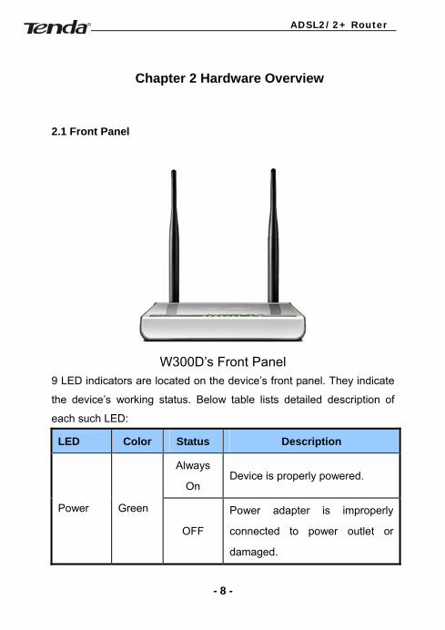
2.1 Front Panel
W300D’s Front Panel
9 LED indicators are located on the device’s front panel. They indicate
the device’s working status. Below table lists detailed description of
each such LED:
LED Color Status Description
Always
On Device is properly powered.
Power Green
OFF
Power adapter is improperly
connected to power outlet or
damaged.
- 8 -
ADSL2/2+ Router
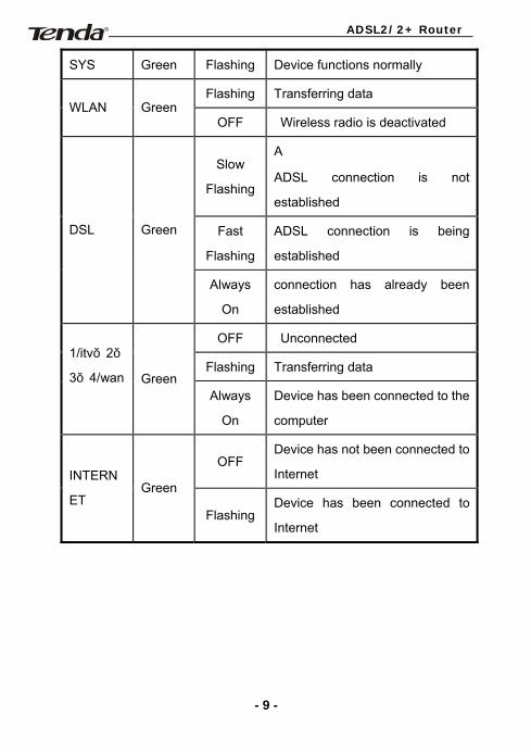
SYS Green Flashing Device functions normally
Flashing Transferring data WLAN Green
OFF Wireless radio is deactivated
Slow
Flashing
A
ADSL connection is not
established
Fast
Flashing
ADSL connection is being
established
DSL Green
Always
On
connection has already been
established
OFF Unconnected
Flashing Transferring data 1/itv,2,
3,4/wan
Green Always
On
Device has been connected to the
computer
OFF Device has not been connected to
Internet INTERN
ET Green
FlashingDevice has been connected to
Internet
- 9 -
ADSL2/2+ Router
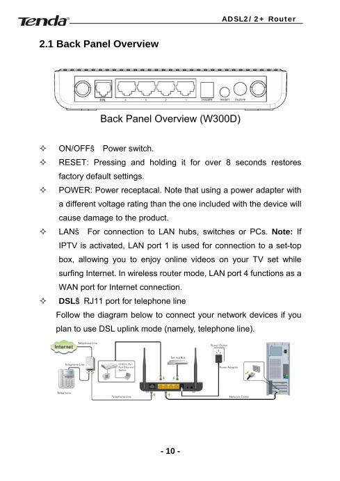
2.1 Back Panel Overview
Back Panel Overview (W300D)
ON/OFF: Power switch.
RESET: Pressing and holding it for over 8 seconds restores
factory default settings.
POWER: Power receptacal. Note that using a power adapter with
a different voltage rating than the one included with the device will
cause damage to the product.
LAN: For connection to LAN hubs, switches or PCs. Note: If
IPTV is activated, LAN port 1 is used for connection to a set-top
box, allowing you to enjoy online videos on your TV set while
surfing Internet. In wireless router mode, LAN port 4 functions as a
WAN port for Internet connection.
DSL:RJ11 port for telephone line
Follow the diagram below to connect your network devices if you
plan to use DSL uplink mode (namely, telephone line).
- 10 -
ADSL2/2+ Router
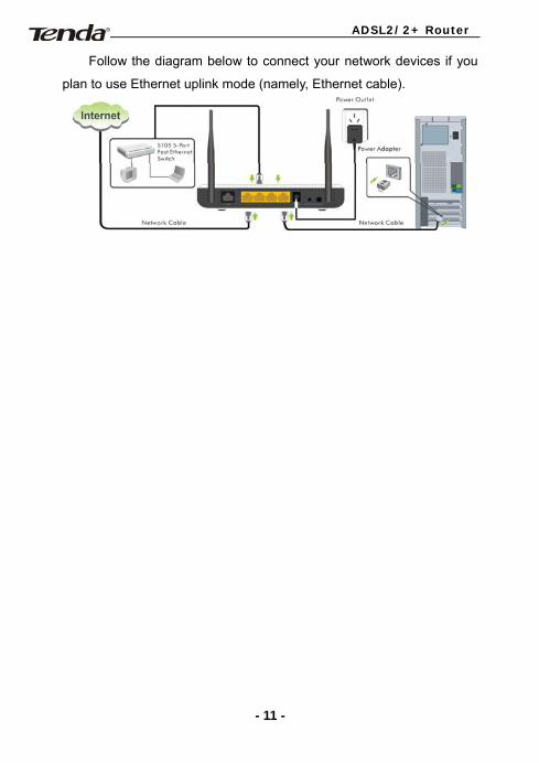
Follow the diagram below to connect your network devices if you
plan to use Ethernet uplink mode (namely, Ethernet cable).
- 11 -
ADSL2/2+ Router
Chapter 3 Quick Setup for Internet Connection
You can log into the device web utility: either via a web browser or
Setup Wizard on the included CD-ROM.
Before configuring the device, you need to config your PC’s TCP/IP
settings.
3.1 Config TCP/IP Settings on PC
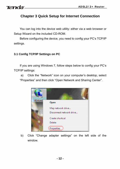
If you are using Windows 7, follow steps below to config your PC’s
TCP/IP settings:
a) Click the “Network” icon on your computer’s desktop, select
“Properties” and then click “Open Network and Sharing Center”.
b) Click “Change adapter settings” on the left side of the
window.
- 12 -
ADSL2/2+ Router
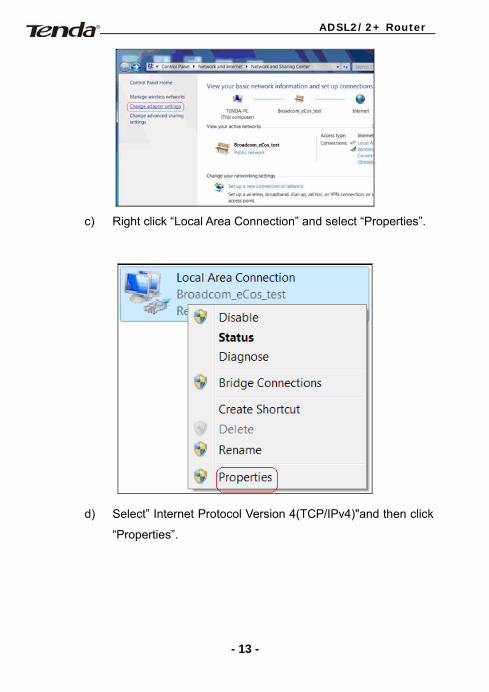
c) Right click “Local Area Connection” and select “Properties”.
d) Select” Internet Protocol Version 4(TCP/IPv4)"and then click
“Properties”.
- 13 -
ADSL2/2+ Router
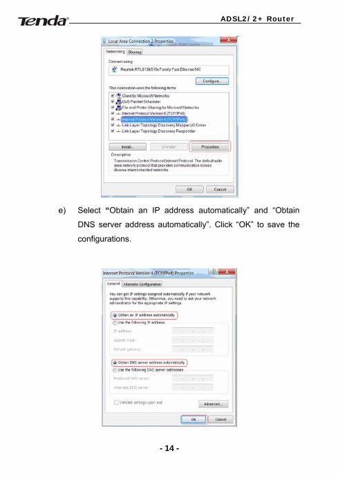
e) Select “Obtain an IP address automatically” and “Obtain
DNS server address automatically”. Click “OK” to save the
configurations.
- 14 -
ADSL2/2+ Router
f) Click OK in the “Local Area Connection Properties” window.
Note: Certainly you can also config your PC’s TCP/IP manually. For
more info, refer to Appendix 1-1.
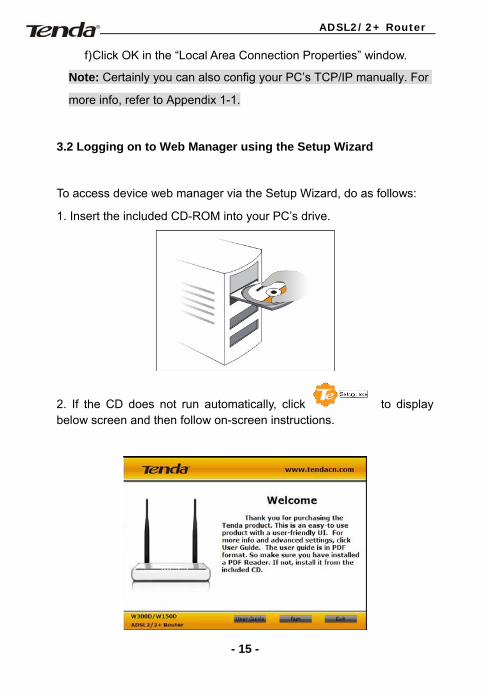
3.2 Logging on to Web Manager using the Setup Wizard
To access device web manager via the Setup Wizard, do as follows:
1. Insert the included CD-ROM into your PC’s drive.
2. If the CD does not run automatically, click to display below screen and then follow on-screen instructions.
- 15 -
ADSL2/2+ Router
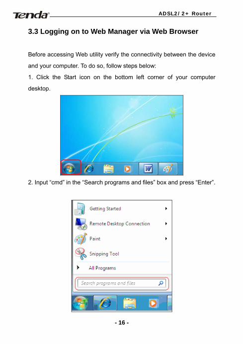
3.3 Logging on to Web Manager via Web Browser
Before accessing Web utility verify the connectivity between the device
and your computer. To do so, follow steps below:
1. Click the Start icon on the bottom left corner of your computer
desktop.
2. Input “cmd” in the “Search programs and files” box and press “Enter”.
- 16 -
ADSL2/2+ Router
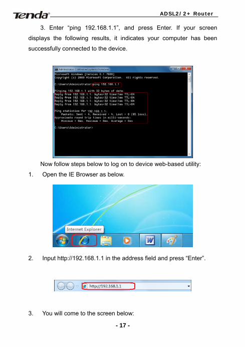
3. Enter “ping 192.168.1.1”, and press Enter. If your screen
displays the following results, it indicates your computer has been
successfully connected to the device.
Now follow steps below to log on to device web-based utility:
1. Open the IE Browser as below.
2. Input http://192.168.1.1 in the address field and press “Enter”.
3. You will come to the screen below:
- 17 -
ADSL2/2+ Router
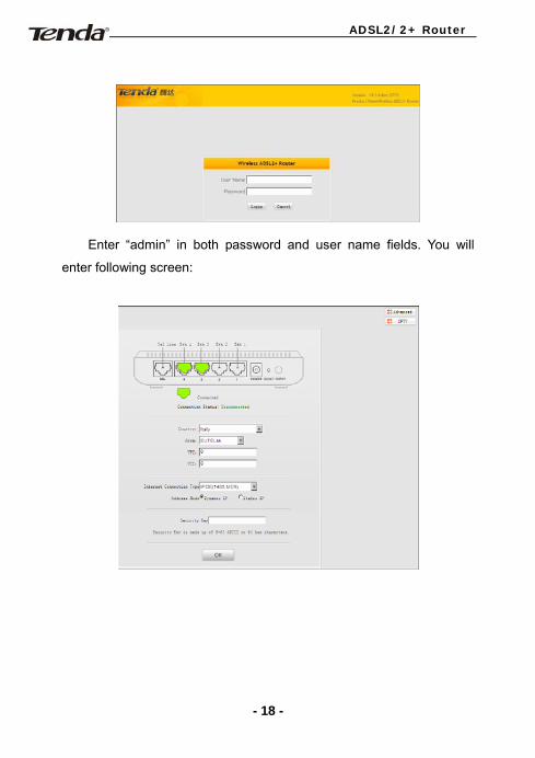
Enter “admin” in both password and user name fields. You will
enter following screen:
- 18 -
ADSL2/2+ Router
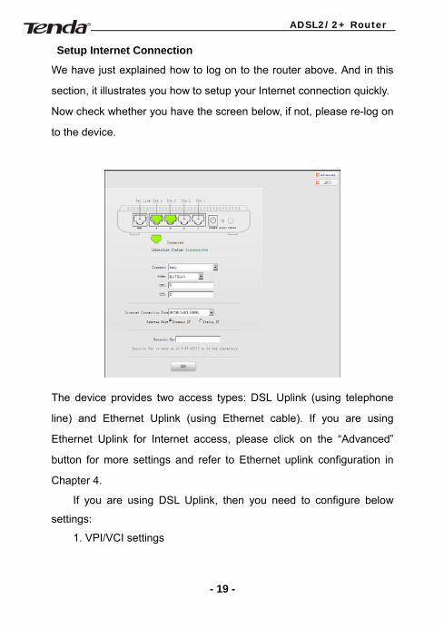
Setup Internet Connection
We have just explained how to log on to the router above. And in this
section, it illustrates you how to setup your Internet connection quickly.
Now check whether you have the screen below, if not, please re-log on
to the device.
The device provides two access types: DSL Uplink (using telephone
line) and Ethernet Uplink (using Ethernet cable). If you are using
Ethernet Uplink for Internet access, please click on the “Advanced”
button for more settings and refer to Ethernet uplink configuration in
Chapter 4.
If you are using DSL Uplink, then you need to configure below
settings:
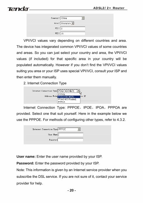
1. VPI/VCI settings
- 19 -
ADSL2/2+ Router
VPI/VCI values vary depending on different countries and area.
The device has integerated common VPI/VCI values of some countries
and areas. So you can just select your country and area, the VPI/VCI
values (if included) for that specific area in your country will be
populated automatically. However if you don’t find the VPI/VCI values
suiting you area or your ISP uses special VPI/VCI, consult your ISP and
then enter them manually.
2. Internet Connection Type
Internet Connection Type: PPPOE,IPOE,IPOA,PPPOA are
provided. Select one that suit yourself. Here in the example below we
use the PPPOE. For methods of configuring other types, refer to 4.3.2.
User name: Enter the user name provided by your ISP.
Password: Enter the password provided by your ISP.
Note: This information is given by an Internet service provider when you
subscribe the DSL service. If you are not sure of it, contact your service
provider for help.
- 20 -
ADSL2/2+ Router
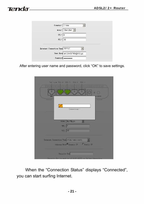
After entering user name and password, click “OK” to save settings.
When the “Connection Status” displays “Connected”,
you can start surfing Internet.
- 21 -
ADSL2/2+ Router
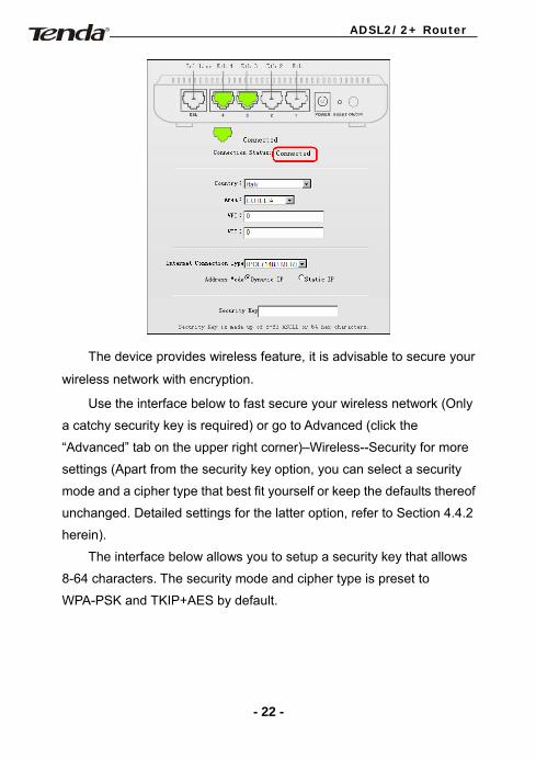
The device provides wireless feature, it is advisable to secure your
wireless network with encryption.
Use the interface below to fast secure your wireless network (Only
a catchy security key is required) or go to Advanced (click the
“Advanced” tab on the upper right corner)–Wireless--Security for more
settings (Apart from the security key option, you can select a security
mode and a cipher type that best fit yourself or keep the defaults thereof
unchanged. Detailed settings for the latter option, refer to Section 4.4.2
herein).
The interface below allows you to setup a security key that allows
8-64 characters. The security mode and cipher type is preset to
WPA-PSK and TKIP+AES by default.
- 22 -
ADSL2/2+ Router
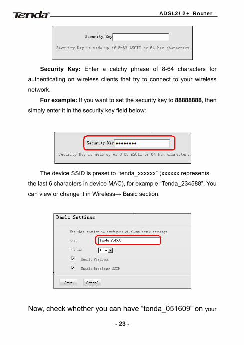
Security Key: Enter a catchy phrase of 8-64 characters for
authenticating on wireless clients that try to connect to your wireless
network.
For example: If you want to set the security key to 88888888, then
simply enter it in the security key field below:
The device SSID is preset to “tenda_xxxxxx” (xxxxxx represents
the last 6 characters in device MAC), for example “Tenda_234588”. You
can view or change it in Wireless→ Basic section.
Now, check whether you can have “tenda_051609” on your
- 23 -
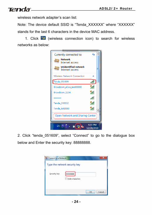
ADSL2/2+ Router
wireless network adapter’s scan list:
Note: The device default SSID is “Tenda_XXXXXX” where “XXXXXX”
stands for the last 6 characters in the device MAC address.
1. Click (wireless connection icon) to search for wireless
networks as below:
2. Click “tenda_051609”, select “Connect” to go to the dialogue box
below and Enter the security key: 88888888.
- 24 -

ADSL2/2+ Router
3. Click “OK” and device will automatically connect such wireless
adapter to the wireless network in a while.
Advanced settings provide you more and powerful functionalities such
as bandwidth control, access control and port forwarding, etc. Read
sections hereunder if you'd like to know more.
- 25 -
ADSL2/2+ Router
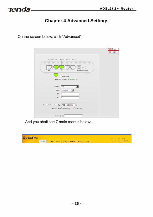
Chapter 4 Advanced Settings
On the screen below, click “Advanced”:
And you shall see 7 main menus below:
- 26 -
ADSL2/2+ Router
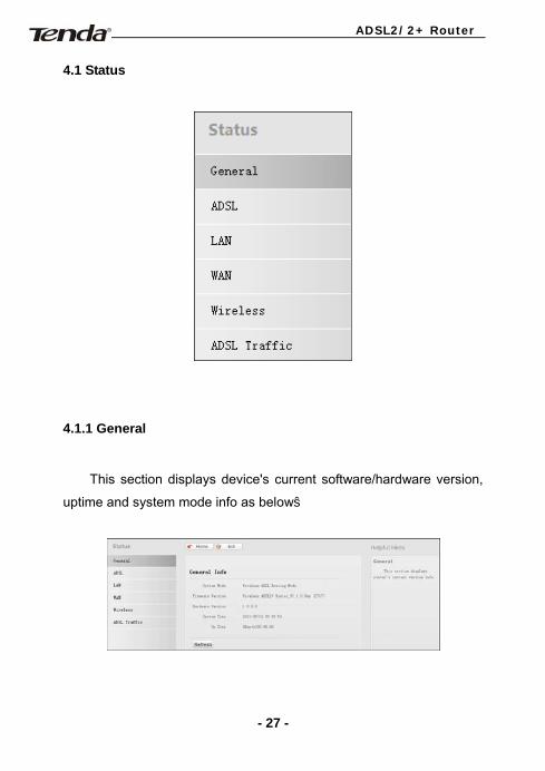
4.1 Status
4.1.1 General
This section displays device's current software/hardware version,
uptime and system mode info as below:
- 27 -
ADSL2/2+ Router
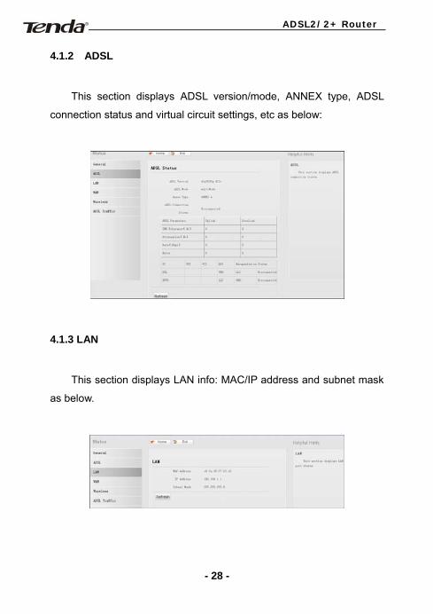
4.1.2 ADSL
This section displays ADSL version/mode, ANNEX type, ADSL
connection status and virtual circuit settings, etc as below:
4.1.3 LAN
This section displays LAN info: MAC/IP address and subnet mask
as below.
- 28 -
ADSL2/2+ Router
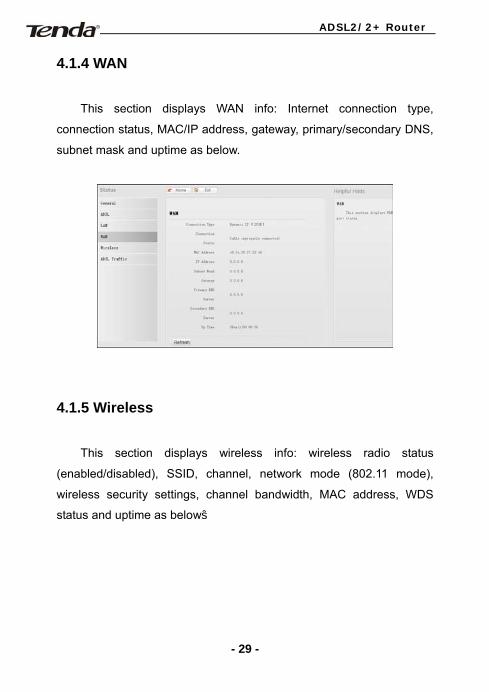
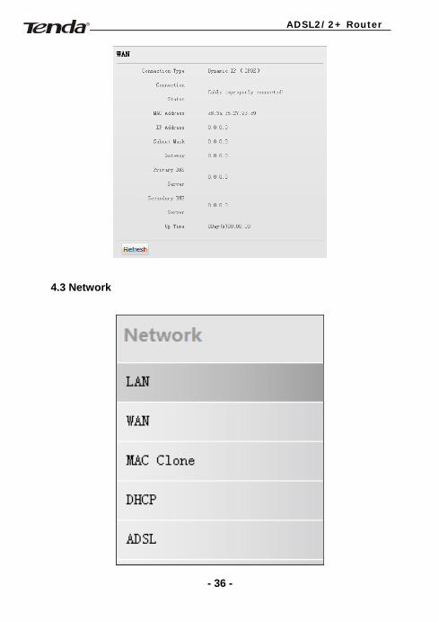
4.1.4 WAN
This section displays WAN info: Internet connection type,
connection status, MAC/IP address, gateway, primary/secondary DNS,
subnet mask and uptime as below.
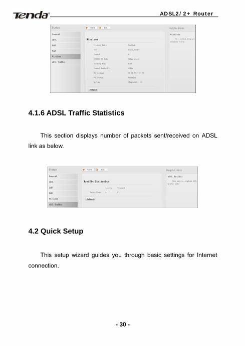
4.1.5 Wireless
This section displays wireless info: wireless radio status
(enabled/disabled), SSID, channel, network mode (802.11 mode),
wireless security settings, channel bandwidth, MAC address, WDS
status and uptime as below:
- 29 -
ADSL2/2+ Router
4.1.6 ADSL Traffic Statistics
This section displays number of packets sent/received on ADSL
link as below.
4.2 Quick Setup
This setup wizard guides you through basic settings for Internet
connection.
- 30 -
ADSL2/2+ Router
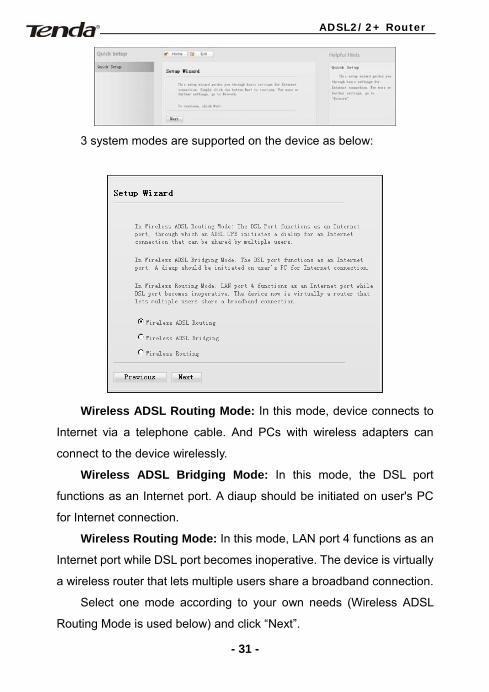
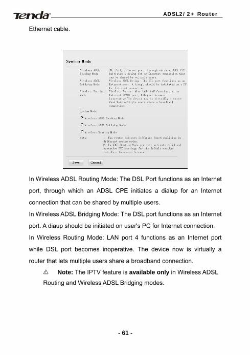
3 system modes are supported on the device as below:
Wireless ADSL Routing Mode: In this mode, device connects to
Internet via a telephone cable. And PCs with wireless adapters can
connect to the device wirelessly.
Wireless ADSL Bridging Mode: In this mode, the DSL port
functions as an Internet port. A diaup should be initiated on user's PC
for Internet connection.
Wireless Routing Mode: In this mode, LAN port 4 functions as an
Internet port while DSL port becomes inoperative. The device is virtually
a wireless router that lets multiple users share a broadband connection.
Select one mode according to your own needs (Wireless ADSL
Routing Mode is used below) and click “Next”.
- 31 -
ADSL2/2+ Router
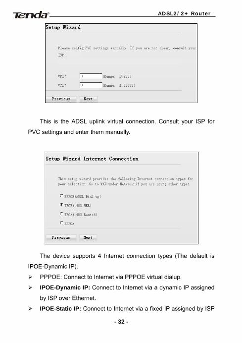
This is the ADSL uplink virtual connection. Consult your ISP for
PVC settings and enter them manually.
The device supports 4 Internet connection types (The default is
IPOE-Dynamic IP).
PPPOE: Connect to Internet via PPPOE virtual dialup.
IPOE-Dynamic IP: Connect to Internet via a dynamic IP assigned
by ISP over Ethernet.
IPOE-Static IP: Connect to Internet via a fixed IP assigned by ISP
- 32 -
ADSL2/2+ Router
over Ethernet.
IPOA-Dynamic IP: Connect to Internet via a dynamic IP over ATM.
IPOA- Static IP: Connect to Internet via a fixed IP over ATM.
PPPOA: Connect to Internet via PPPOE virtual dialup over ATM.
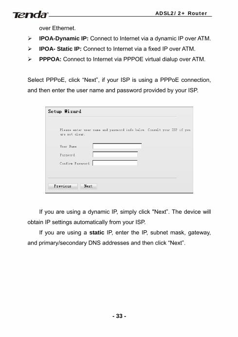
Select PPPoE, click “Next”, if your ISP is using a PPPoE connection,
and then enter the user name and password provided by your ISP.
If you are using a dynamic IP, simply click "Next”. The device will
obtain IP settings automatically from your ISP.
If you are using a static IP, enter the IP, subnet mask, gateway,
and primary/secondary DNS addresses and then click “Next”.
- 33 -
ADSL2/2+ Router
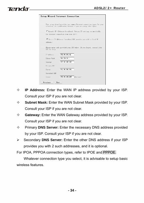
IP Address: Enter the WAN IP address provided by your ISP.
Consult your ISP if you are not clear.
Subnet Mask: Enter the WAN Subnet Mask provided by your ISP.
Consult your ISP if you are not clear.
Gateway: Enter the WAN Gateway address provided by your ISP.
Consult your ISP if you are not clear.
Primary DNS Server: Enter the necessary DNS address provided
by your ISP. Consult your ISP if you are not clear.
Secondary DNS Server: Enter the other DNS address if your ISP
provides you with 2 such addresses, and it is optional.
For IPOA, PPPOA connection types, refer to IPOE and PPPOE.
Whatever connection type you select, it is advisable to setup basic
wireless features.
- 34 -
ADSL2/2+ Router
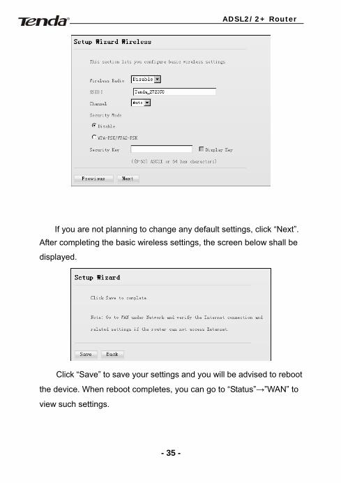
If you are not planning to change any default settings, click “Next”.
After completing the basic wireless settings, the screen below shall be
displayed.
Click “Save” to save your settings and you will be advised to reboot
the device. When reboot completes, you can go to “Status”→”WAN” to
view such settings.
- 35 -
ADSL2/2+ Router
4.3 Network
- 36 -
ADSL2/2+ Router
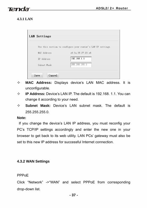
4.3.1 LAN
MAC Address: Displays device’s LAN MAC address. It is
unconfigurable. IP Address: Device’s LAN IP. The default is 192.168. 1.1. You can
change it according to your need.
Subnet Mask: Device’s LAN subnet mask. The default is
255.255.255.0. Note: If you change the device’s LAN IP address, you must reconfig your
PC’s TCP/IP settings accordingly and enter the new one in your
browser to get back to its web utility. LAN PCs’ gateway must also be
set to this new IP address for successful Internet connection.
4.3.2 WAN Settings
PPPoE
Click “Network” ->“WAN” and select PPPoE from corresponding
drop-down list. - 37 -
ADSL2/2+ Router
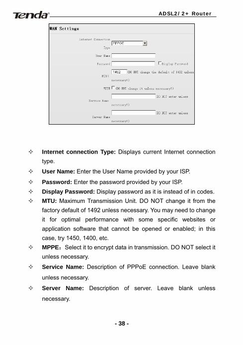
Internet connection Type: Displays current Internet connection type.
User Name: Enter the User Name provided by your ISP.
Password: Enter the password provided by your ISP. Display Password: Display password as it is instead of in codes. MTU: Maximum Transmission Unit. DO NOT change it from the
factory default of 1492 unless necessary. You may need to change it for optimal performance with some specific websites or application software that cannot be opened or enabled; in this case, try 1450, 1400, etc.
MPPE:Select it to encrypt data in transmission. DO NOT select it unless necessary.
Service Name: Description of PPPoE connection. Leave blank
unless necessary.
Server Name: Description of server. Leave blank unless
necessary.
- 38 -
ADSL2/2+ Router
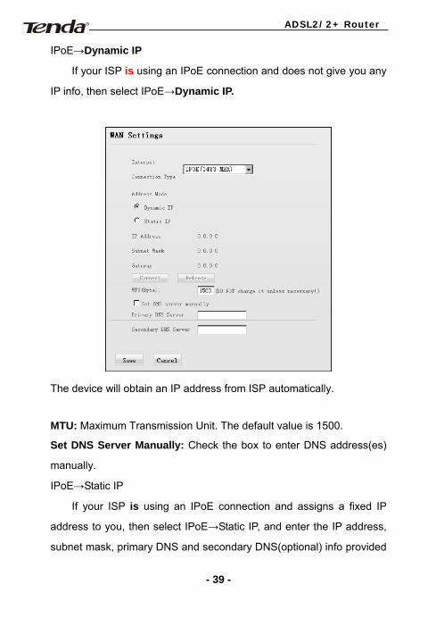
IPoE→Dynamic IP
If your ISP is using an IPoE connection and does not give you any
IP info, then select IPoE→Dynamic IP.
The device will obtain an IP address from ISP automatically.
MTU: Maximum Transmission Unit. The default value is 1500.
Set DNS Server Manually: Check the box to enter DNS address(es)
manually.
IPoE→Static IP
If your ISP is using an IPoE connection and assigns a fixed IP
address to you, then select IPoE→Static IP, and enter the IP address,
subnet mask, primary DNS and secondary DNS(optional) info provided
- 39 -
ADSL2/2+ Router
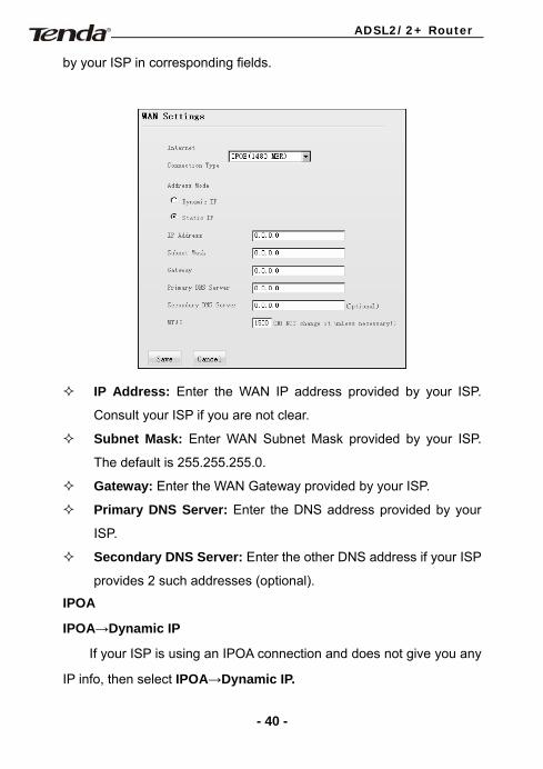
by your ISP in corresponding fields.
IP Address: Enter the WAN IP address provided by your ISP.
Consult your ISP if you are not clear.
Subnet Mask: Enter WAN Subnet Mask provided by your ISP.
The default is 255.255.255.0.
Gateway: Enter the WAN Gateway provided by your ISP.
Primary DNS Server: Enter the DNS address provided by your
ISP.
Secondary DNS Server: Enter the other DNS address if your ISP
provides 2 such addresses (optional).
IPOA
IPOA→Dynamic IP
If your ISP is using an IPOA connection and does not give you any
IP info, then select IPOA→Dynamic IP.
- 40 -
ADSL2/2+ Router
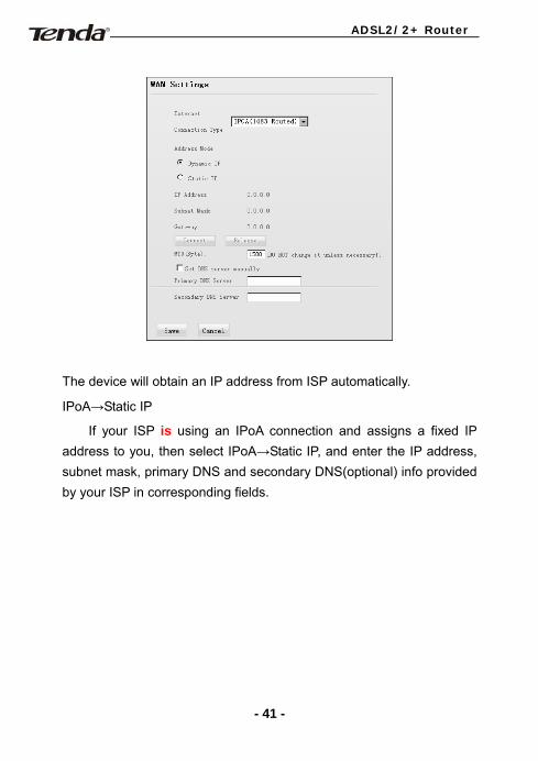
The device will obtain an IP address from ISP automatically.
IPoA→Static IP
If your ISP is using an IPoA connection and assigns a fixed IP address to you, then select IPoA→Static IP, and enter the IP address, subnet mask, primary DNS and secondary DNS(optional) info provided by your ISP in corresponding fields.
- 41 -
ADSL2/2+ Router
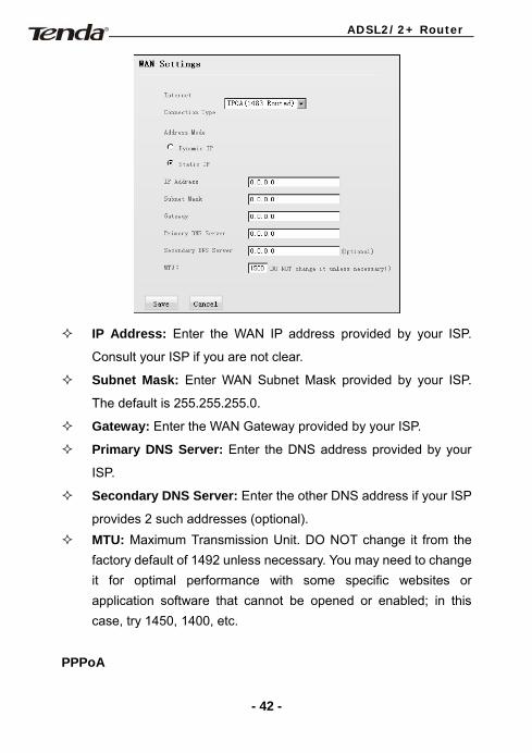
IP Address: Enter the WAN IP address provided by your ISP.
Consult your ISP if you are not clear.
Subnet Mask: Enter WAN Subnet Mask provided by your ISP.
The default is 255.255.255.0.
Gateway: Enter the WAN Gateway provided by your ISP.
Primary DNS Server: Enter the DNS address provided by your
ISP.
Secondary DNS Server: Enter the other DNS address if your ISP
provides 2 such addresses (optional). MTU: Maximum Transmission Unit. DO NOT change it from the
factory default of 1492 unless necessary. You may need to change it for optimal performance with some specific websites or application software that cannot be opened or enabled; in this case, try 1450, 1400, etc.
PPPoA
- 42 -
ADSL2/2+ Router
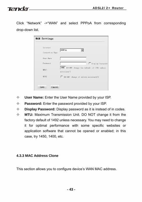
Click “Network” ->“WAN” and select PPPoA from corresponding
drop-down list.
User Name: Enter the User Name provided by your ISP.
Password: Enter the password provided by your ISP. Display Password: Display password as it is instead of in codes. MTU: Maximum Transmission Unit. DO NOT change it from the
factory default of 1492 unless necessary. You may need to change it for optimal performance with some specific websites or application software that cannot be opened or enabled; in this case, try 1450, 1400, etc.
4.3.3 MAC Address Clone
This section allows you to configure device’s WAN MAC address.
- 43 -
ADSL2/2+ Router
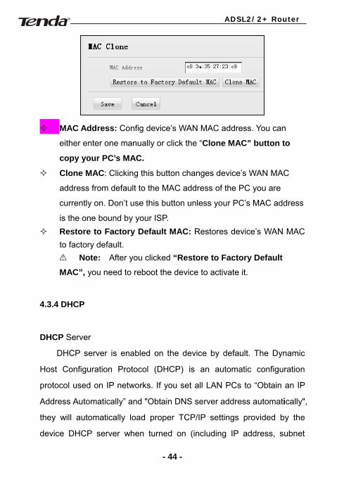
MAC Address: Config device’s WAN MAC address. You can
either enter one manually or click the “Clone MAC” button to
copy your PC’s MAC.
Clone MAC: Clicking this button changes device’s WAN MAC
address from default to the MAC address of the PC you are
currently on. Don’t use this button unless your PC’s MAC address
is the one bound by your ISP. Restore to Factory Default MAC: Restores device’s WAN MAC
to factory default. Note: After you clicked “Restore to Factory Default
MAC”, you need to reboot the device to activate it.
4.3.4 DHCP
DHCP Server
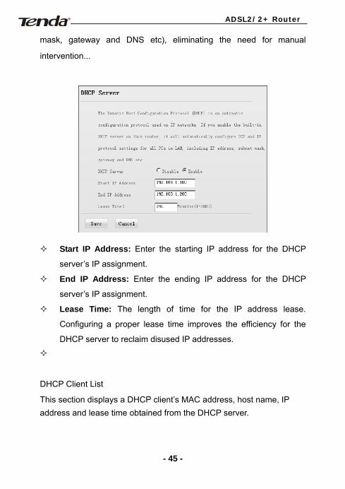
DHCP server is enabled on the device by default. The Dynamic
Host Configuration Protocol (DHCP) is an automatic configuration
protocol used on IP networks. If you set all LAN PCs to “Obtain an IP
Address Automatically” and "Obtain DNS server address automatically",
they will automatically load proper TCP/IP settings provided by the
device DHCP server when turned on (including IP address, subnet
- 44 -
ADSL2/2+ Router
mask, gateway and DNS etc), eliminating the need for manual
intervention...
Start IP Address: Enter the starting IP address for the DHCP
server’s IP assignment.
End IP Address: Enter the ending IP address for the DHCP
server’s IP assignment.
Lease Time: The length of time for the IP address lease.
Configuring a proper lease time improves the efficiency for the
DHCP server to reclaim disused IP addresses.
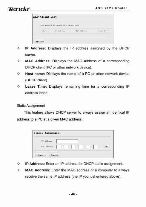
DHCP Client List
This section displays a DHCP client’s MAC address, host name, IP address and lease time obtained from the DHCP server.
- 45 -
ADSL2/2+ Router
IP Address: Displays the IP address assigned by the DHCP
server.
MAC Address: Displays the MAC address of a corresponding
DHCP client (PC or other network device).
Host name: Displays the name of a PC or other network device
(DHCP client).
Lease Time: Displays remaining time for a corresponding IP
address lease.
Static Assignment
This feature allows DHCP server to always assign an identical IP
address to a PC at a given MAC address.
IP Address: Enter an IP address for DHCP static assignment.
MAC Address: Enter the MAC address of a computer to always
receive the same IP address (the IP you just entered above).
- 46 -
ADSL2/2+ Router
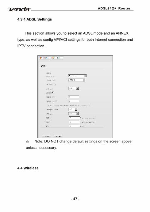
4.3.4 ADSL Settings
This section allows you to select an ADSL mode and an ANNEX
type, as well as config VPI/VCI settings for both Internet connection and
IPTV connection.
Note: DO NOT change default settings on the screen above
unless neccessary.
4.4 Wireless
- 47 -
ADSL2/2+ Router
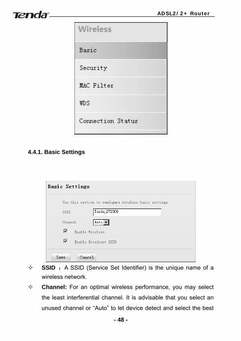
4.4.1. Basic Settings
SSID :A SSID (Service Set Identifier) is the unique name of a
wireless network.
Channel: For an optimal wireless performance, you may select
the least interferential channel. It is advisable that you select an
unused channel or “Auto” to let device detect and select the best
- 48 -
ADSL2/2+ Router
possible channel for your wireless network to operate on from the
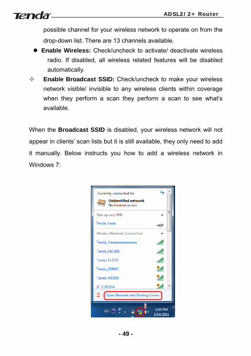
drop-down list. There are 13 channels available. Enable Wireless: Check/uncheck to activate/ deactivate wireless
radio. If disabled, all wireless related features will be disabled automatically.
Enable Broadcast SSID: Check/uncheck to make your wireless network visible/ invisible to any wireless clients within coverage when they perform a scan they perform a scan to see what’s available.
When the Broadcast SSID is disabled, your wireless network will not
appear in clients’ scan lists but it is still available, they only need to add
it manually. Below instructs you how to add a wireless network in
Windows 7:
- 49 -
ADSL2/2+ Router
Step1: Click icon on bottom right corner as seen in the
screenshot above.
Step2: Click “Open Network and Sharing Center” to display the
screen below.
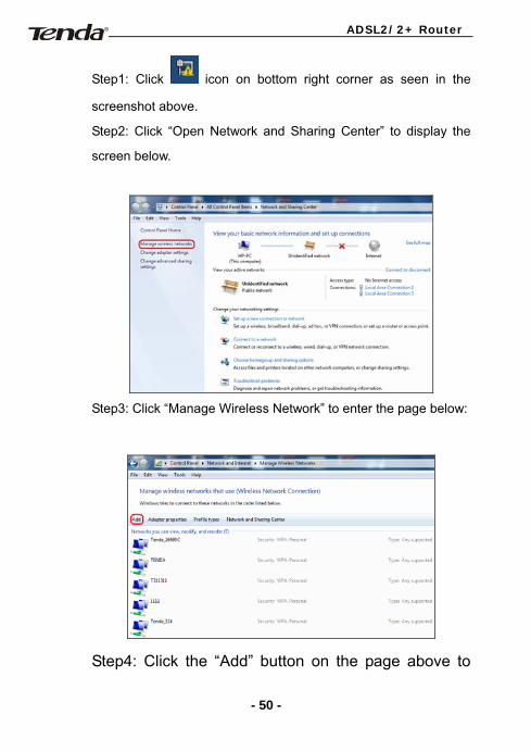
Step3: Click “Manage Wireless Network” to enter the page below:
Step4: Click the “Add” button on the page above to
- 50 -
ADSL2/2+ Router
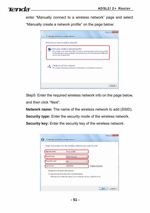
enter “Manually connect to a wireless network” page and select
“Manually create a network profile” on the page below:
Step5: Enter the required wireless network info on the page below,
and then click “Next”.
Network name: The name of the wireless network to add (SSID).
Security type: Enter the security mode of the wireless network.
Security key: Enter the security key of the wireless network.
- 51 -
ADSL2/2+ Router
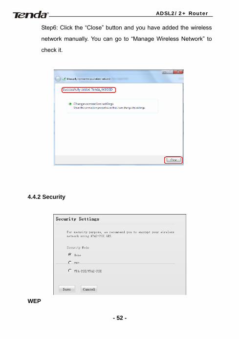
Step6: Click the “Close” button and you have added the wireless
network manually. You can go to “Manage Wireless Network” to
check it.
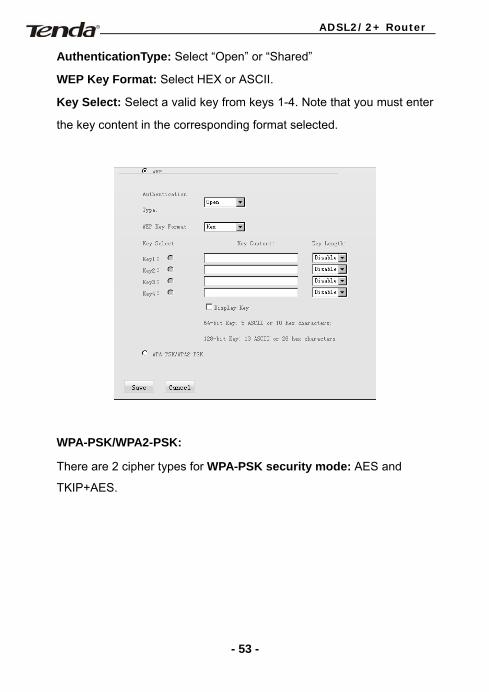
4.4.2 Security
WEP
- 52 -
ADSL2/2+ Router
AuthenticationType: Select “Open” or “Shared”
WEP Key Format: Select HEX or ASCII.
Key Select: Select a valid key from keys 1-4. Note that you must enter
the key content in the corresponding format selected.
WPA-PSK/WPA2-PSK:
There are 2 cipher types for WPA-PSK security mode: AES and
TKIP+AES.
- 53 -
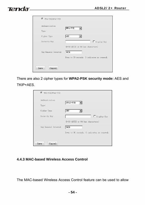
ADSL2/2+ Router
There are also 2 cipher types for WPA2-PSK security mode: AES and
TKIP+AES.
4.4.3 MAC-based Wireless Access Control
The MAC-based Wireless Access Control feature can be used to allow
- 54 -
ADSL2/2+ Router
or disallow clients at specific MAC addresses to connect to your
wireless network.
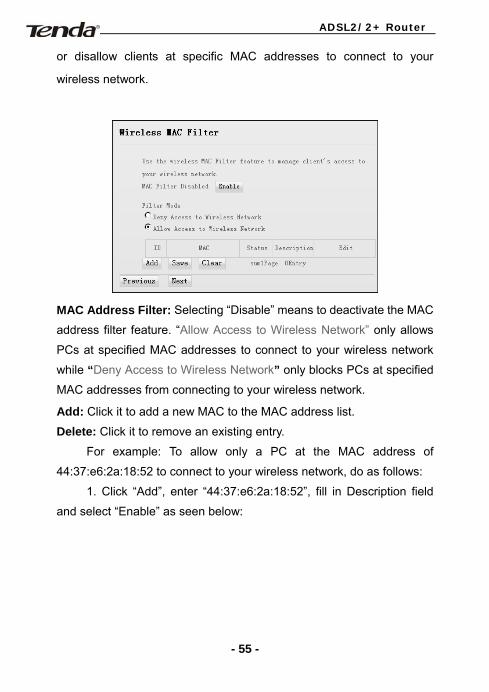
MAC Address Filter: Selecting “Disable” means to deactivate the MAC
address filter feature. “Allow Access to Wireless Network” only allows
PCs at specified MAC addresses to connect to your wireless network
while “Deny Access to Wireless Network” only blocks PCs at specified
MAC addresses from connecting to your wireless network.
Add: Click it to add a new MAC to the MAC address list.
Delete: Click it to remove an existing entry.
For example: To allow only a PC at the MAC address of
44:37:e6:2a:18:52 to connect to your wireless network, do as follows:
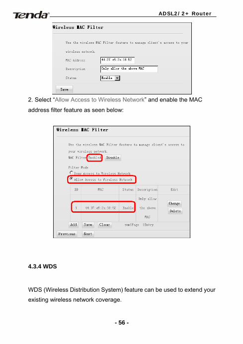
1. Click “Add”, enter “44:37:e6:2a:18:52”, fill in Description field
and select “Enable” as seen below:
- 55 -
ADSL2/2+ Router
2. Select “Allow Access to Wireless Network” and enable the MAC
address filter feature as seen below:
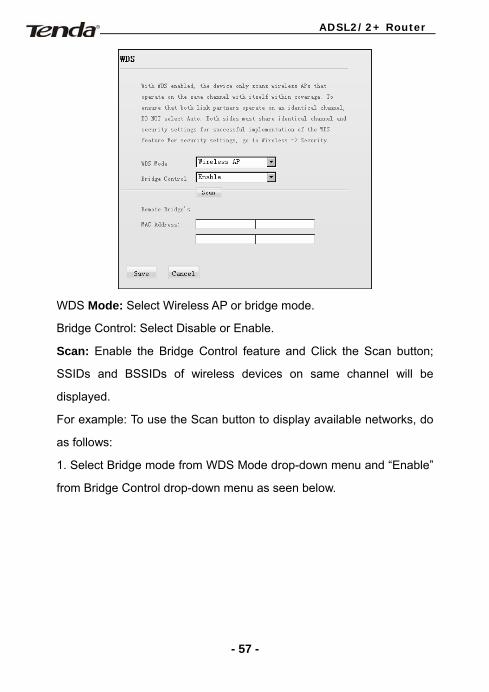
4.3.4 WDS
WDS (Wireless Distribution System) feature can be used to extend your
existing wireless network coverage.
- 56 -
ADSL2/2+ Router
WDS Mode: Select Wireless AP or bridge mode.
Bridge Control: Select Disable or Enable.
Scan: Enable the Bridge Control feature and Click the Scan button;
SSIDs and BSSIDs of wireless devices on same channel will be
displayed.
For example: To use the Scan button to display available networks, do
as follows:
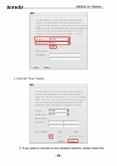
1. Select Bridge mode from WDS Mode drop-down menu and “Enable”
from Bridge Control drop-down menu as seen below.
- 57 -
ADSL2/2+ Router
2. Click the “Scan” button.
3. If you want to connect to any wireless network, simply check the
- 58 -
ADSL2/2+ Router
box next to such network and click “Connect”. And device will connect
to it automatically.
Note:
1. WDS feature can only be implemented between 2 wireless
devices that both support the WDS feature.
2. SSID, channel, security settings and security key must be
the same on both such devices.
3. The device only supports WEP encryption for this feature.
4. It is advisable to disable device’s built-in DHCP server
when using the WDS feature
5. Device LAN IP must be set to the same IP net segment as
link partner when using the WDS feature.
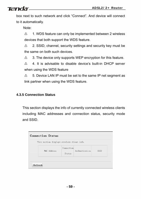
4.3.5 Connection Status
This section displays the info of currently connected wireless clients
including MAC addresses and connection status, security mode
and SSID.
- 59 -
ADSL2/2+ Router
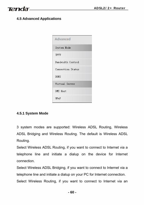
4.5 Advanced Applications
4.5.1 System Mode
3 system modes are supported: Wireless ADSL Routing, Wireless
ADSL Bridging and Wireless Routing. The default is Wireless ADSL
Routing.
Select Wireless ADSL Routing, if you want to connect to Internet via a
telephone line and initiate a dialup on the device for Internet
connection.
Select Wireless ADSL Bridging, if you want to connect to Internet via a
telephone line and initiate a dialup on your PC for Internet connection.
Select Wireless Routing, if you want to connect to Internet via an
- 60 -
ADSL2/2+ Router
Ethernet cable.
In Wireless ADSL Routing Mode: The DSL Port functions as an Internet
port, through which an ADSL CPE initiates a dialup for an Internet
connection that can be shared by multiple users.
In Wireless ADSL Bridging Mode: The DSL port functions as an Internet
port. A diaup should be initiated on user's PC for Internet connection.
In Wireless Routing Mode: LAN port 4 functions as an Internet port
while DSL port becomes inoperative. The device now is virtually a
router that lets multiple users share a broadband connection.
Note: The IPTV feature is available only in Wireless ADSL
Routing and Wireless ADSL Bridging modes.
- 61 -
ADSL2/2+ Router
4.5.2 IPTV
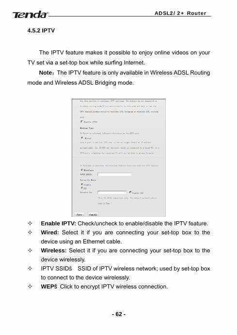
The IPTV feature makes it possible to enjoy online videos on your
TV set via a set-top box while surfing Internet.
Note:The IPTV feature is only available in Wireless ADSL Routing
mode and Wireless ADSL Bridging mode.
Enable IPTV: Check/uncheck to enable/disable the IPTV feature. Wired: Select it if you are connecting your set-top box to the
device using an Ethernet cable. Wireless: Select it if you are connecting your set-top box to the
device wirelessly. IPTV SSID: SSID of IPTV wireless network; used by set-top box
to connect to the device wirelessly. WEP:Click to encrypt IPTV wireless connection.
- 62 -
ADSL2/2+ Router
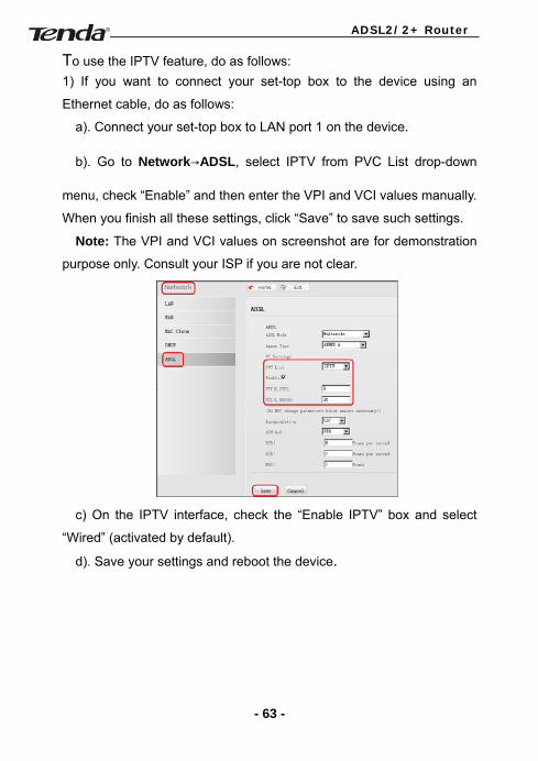
To use the IPTV feature, do as follows: 1) If you want to connect your set-top box to the device using an
Ethernet cable, do as follows:
a). Connect your set-top box to LAN port 1 on the device.
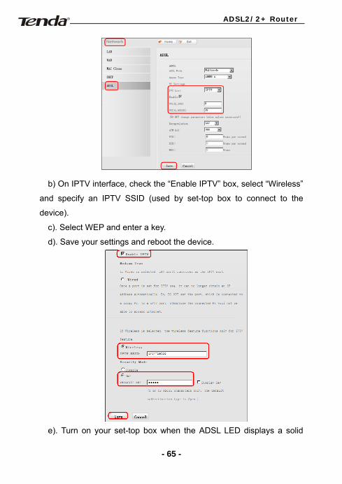
b). Go to Network→ADSL, select IPTV from PVC List drop-down
menu, check “Enable” and then enter the VPI and VCI values manually.
When you finish all these settings, click “Save” to save such settings.
Note: The VPI and VCI values on screenshot are for demonstration
purpose only. Consult your ISP if you are not clear.
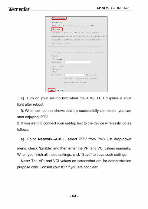
c) On the IPTV interface, check the “Enable IPTV” box and select
“Wired” (activated by default).
d). Save your settings and reboot the device.
- 63 -
ADSL2/2+ Router
e). Turn on your set-top box when the ADSL LED displays a solid
light after reboot.
f). When set-top box shows that it is successfully connected, you can
start enjoying IPTV.
2) If you want to connect your set-top box to the device wirelessly, do as
follows:
a). Go to Network→ADSL, select IPTV from PVC List drop-down
menu, check “Enable” and then enter the VPI and VCI values manually.
When you finish all these settings, click “Save” to save such settings.
Note: The VPI and VCI values on screenshot are for demonstration
purpose only. Consult your ISP if you are not clear.
- 64 -
ADSL2/2+ Router
b) On IPTV interface, check the “Enable IPTV” box, select “Wireless”
and specify an IPTV SSID (used by set-top box to connect to the
device).
c). Select WEP and enter a key.
d). Save your settings and reboot the device.
e). Turn on your set-top box when the ADSL LED displays a solid
- 65 -
ADSL2/2+ Router
light after reboot.
f). On your set-top box management interface, select “Wireless”,
enter the IPTV SSID and security key to connect to the device.
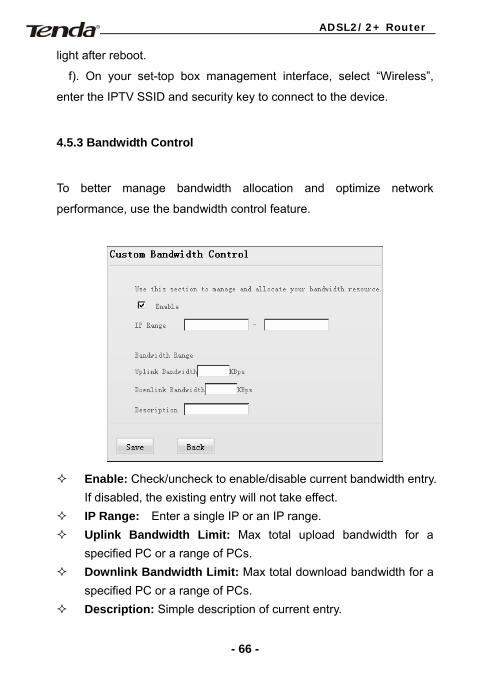
4.5.3 Bandwidth Control
To better manage bandwidth allocation and optimize network
performance, use the bandwidth control feature.
Enable: Check/uncheck to enable/disable current bandwidth entry.
If disabled, the existing entry will not take effect. IP Range: Enter a single IP or an IP range. Uplink Bandwidth Limit: Max total upload bandwidth for a
specified PC or a range of PCs. Downlink Bandwidth Limit: Max total download bandwidth for a
specified PC or a range of PCs. Description: Simple description of current entry.
- 66 -
ADSL2/2+ Router
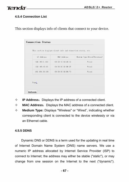
4.5.4 Connection List
This section displays info of clients that connect to your device.
IP Address:Displays the IP address of a connected client.
MAC Address:Displays the MAC address of a connected client.
Medium Type: Displays "Wireless" or “Wired”, indicating whether
corresponding client is connected to the device wirelessly or via
an Ethernet cable.
4.5.5 DDNS
Dynamic DNS or DDNS is a term used for the updating in real time
of Internet Domain Name System (DNS) name servers. We use a
numeric IP address allocated by Internet Service Provider (ISP) to
connect to Internet; the address may either be stable ("static"), or may
change from one session on the Internet to the next ("dynamic").
- 67 -
ADSL2/2+ Router
However, a numeric address is inconvenient to remember; an address
which changes unpredictably makes connection impossible. The DDNS
provider allocates a static hostname to the user; whenever the user is
allocated a new IP address this is communicated to the DDNS provider
by software running on a computer or network device at that address;
the provider distributes the association between the hostname and the
address to the Internet's DNS servers so that they may resolve DNS
queries. Thus, uninterrupted access to devices and services whose
numeric IP address may change is maintained.
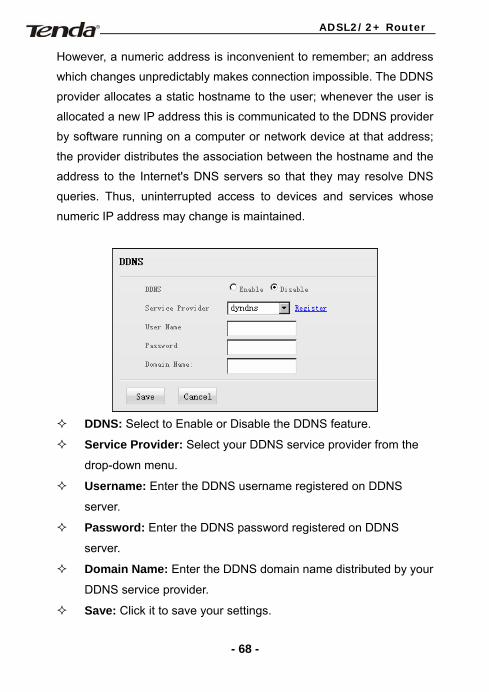
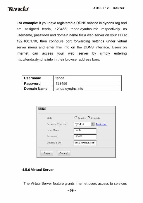
DDNS: Select to Enable or Disable the DDNS feature.
Service Provider: Select your DDNS service provider from the
drop-down menu.
Username: Enter the DDNS username registered on DDNS
server.
Password: Enter the DDNS password registered on DDNS
server.
Domain Name: Enter the DDNS domain name distributed by your
DDNS service provider.
Save: Click it to save your settings.
- 68 -
ADSL2/2+ Router
For example: If you have registered a DDNS service in dyndns.org and
are assigned tenda, 123456, tenda.dyndns.info respectively as
username, password and domain name for a web server on your PC at
192.168.1.10, then configure port forwarding settings under virtual
server menu and enter this info on the DDNS interface. Users on
Internet can access your web server by simply entering
http://tenda.dyndns.info in their browser address bars.
Username tenda Password 123456 Domain Name tenda.dyndns.info
4.5.6 Virtual Server
The Virtual Server feature grants Internet users access to services
- 69 -
ADSL2/2+ Router
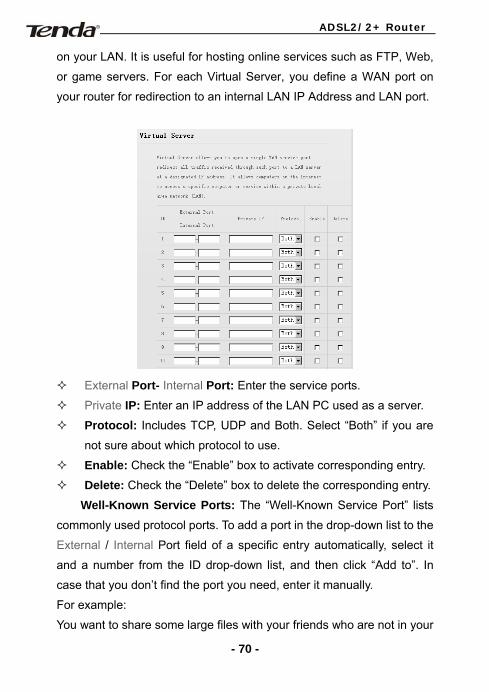
on your LAN. It is useful for hosting online services such as FTP, Web,
or game servers. For each Virtual Server, you define a WAN port on
your router for redirection to an internal LAN IP Address and LAN port.
External Port- Internal Port: Enter the service ports.
Private IP: Enter an IP address of the LAN PC used as a server.
Protocol: Includes TCP, UDP and Both. Select “Both” if you are
not sure about which protocol to use.
Enable: Check the “Enable” box to activate corresponding entry.
Delete: Check the “Delete” box to delete the corresponding entry.
Well-Known Service Ports: The “Well-Known Service Port” lists
commonly used protocol ports. To add a port in the drop-down list to the
External / Internal Port field of a specific entry automatically, select it
and a number from the ID drop-down list, and then click “Add to”. In
case that you don’t find the port you need, enter it manually.
For example:
You want to share some large files with your friends who are not in your
- 70 -
ADSL2/2+ Router
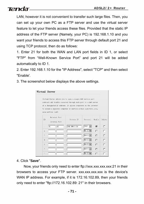
LAN; however it is not convenient to transfer such large files. Then, you
can set up your own PC as a FTP server and use the virtual server
feature to let your friends access these files. Provided that the static IP
address of the FTP server (Namely, your PC) is 192.168.1.10 and you
want your friends to access this FTP server through default port 21 and
using TCP protocol, then do as follows:
1. Enter 21 for both the WAN and LAN port fields in ID 1, or select
"FTP" from “Well-Known Service Port” and port 21 will be added
automatically to ID 1.
2. Enter 192.168.1.10 for the "IP Address", select "TCP" and then select
"Enable'.
3. The screenshot below displays the above settings.
4. Click "Save".
Now, your friends only need to enter ftp://xxx.xxx.xxx.xxx:21 in their browsers to access your FTP server. xxx.xxx.xxx.xxx is the device's WAN IP address. For example, if it is 172.16.102.89, then your friends only need to enter "ftp://172.16.102.89: 21" in their browsers.
- 71 -
ADSL2/2+ Router
Note: If you include port 80 on this section, you must set the port on remote (web-based) management section to a different number than 80, such as 8080, otherwise the virtual server feature may not take effect.
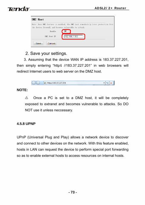
4.5.7 DMZ Host
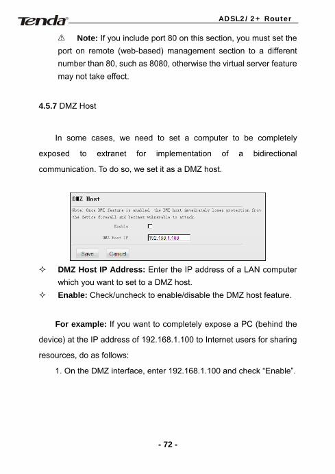
In some cases, we need to set a computer to be completely
exposed to extranet for implementation of a bidirectional
communication. To do so, we set it as a DMZ host.
DMZ Host IP Address: Enter the IP address of a LAN computer
which you want to set to a DMZ host. Enable: Check/uncheck to enable/disable the DMZ host feature.
For example: If you want to completely expose a PC (behind the
device) at the IP address of 192.168.1.100 to Internet users for sharing
resources, do as follows:
1. On the DMZ interface, enter 192.168.1.100 and check “Enable”.
- 72 -
ADSL2/2+ Router
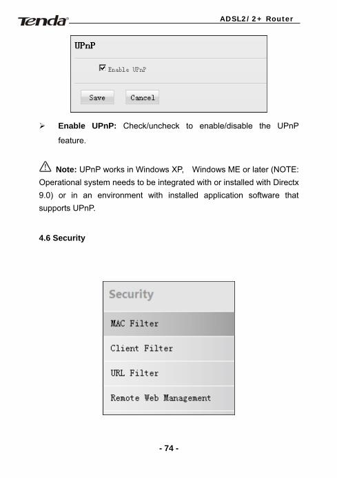
2. Save your settings. 3. Assuming that the device WAN IP address is 183.37.227.201,
then simply entering “http://183.37.227.201” in web browsers will
redirect Internet users to web server on the DMZ host.
NOTE:
Once a PC is set to a DMZ host, it will be completely
exposed to extranet and becomes vulnerable to attacks. So DO
NOT use it unless neccessary.
4.5.8 UPNP
UPnP (Universal Plug and Play) allows a network device to discover
and connect to other devices on the network. With this feature enabled,
hosts in LAN can request the device to perform special port forwarding
so as to enable external hosts to access resources on internal hosts.
- 73 -
ADSL2/2+ Router
Enable UPnP: Check/uncheck to enable/disable the UPnP
feature.
Note: UPnP works in Windows XP, Windows ME or later (NOTE: Operational system needs to be integrated with or installed with Directx 9.0) or in an environment with installed application software that supports UPnP.
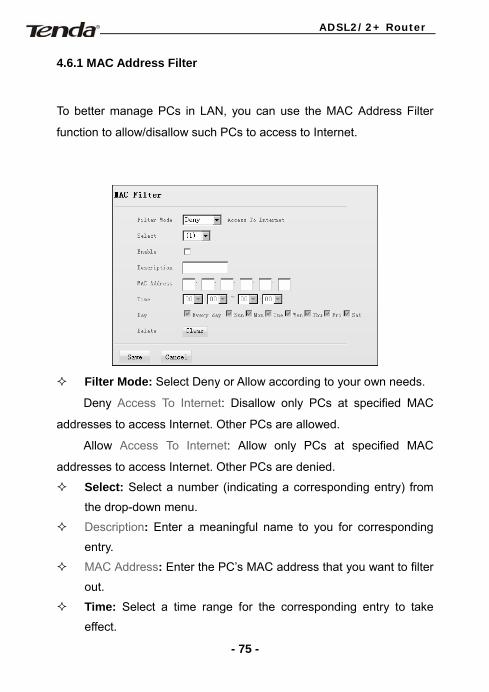
4.6 Security
- 74 -
ADSL2/2+ Router
4.6.1 MAC Address Filter
To better manage PCs in LAN, you can use the MAC Address Filter
function to allow/disallow such PCs to access to Internet.
Filter Mode: Select Deny or Allow according to your own needs.
Deny Access To Internet: Disallow only PCs at specified MAC
addresses to access Internet. Other PCs are allowed.
Allow Access To Internet: Allow only PCs at specified MAC
addresses to access Internet. Other PCs are denied.
Select: Select a number (indicating a corresponding entry) from
the drop-down menu.
Description: Enter a meaningful name to you for corresponding
entry.
MAC Address: Enter the PC’s MAC address that you want to filter
out.
Time: Select a time range for the corresponding entry to take
effect.
- 75 -
ADSL2/2+ Router
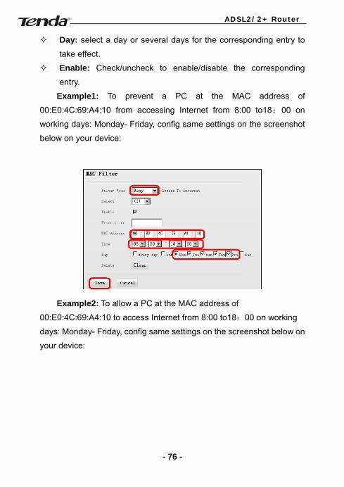
Day: select a day or several days for the corresponding entry to
take effect.
Enable: Check/uncheck to enable/disable the corresponding
entry.
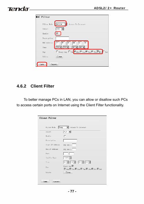
Example1: To prevent a PC at the MAC address of
00:E0:4C:69:A4:10 from accessing Internet from 8:00 to18:00 on
working days: Monday- Friday, config same settings on the screenshot
below on your device:
Example2: To allow a PC at the MAC address of
00:E0:4C:69:A4:10 to access Internet from 8:00 to18:00 on working
days: Monday- Friday, config same settings on the screenshot below on
your device:
- 76 -
ADSL2/2+ Router
4.6.2 Client Filter
To better manage PCs in LAN, you can allow or disallow such PCs to access certain ports on Internet using the Client Filter functionality.
- 77 -
ADSL2/2+ Router
Filter Mode: Select Deny or Allow according to your own needs.
Select: Select a number (indicating a filter rule) from the
drop-down menu.
Description: Enter a meaningful name to yourself for a new filter
rule.
Start /End IP Address: Enter a starting/ending IP address.
Port: Enter TCP/UDP protocol port number (s); it can be a range
of ports or a single port.
Traffic Type: Select a protocol or protocols for the traffic
(TCP/UDP/Both).
Time: Select a time range for the rule to take effect.
Day: Select a day or several days for the rule to take effect.
Enable: Check to enable or uncheck to disable a corresponding
filter rule ( allow/disallow matched packets to pass through
router).
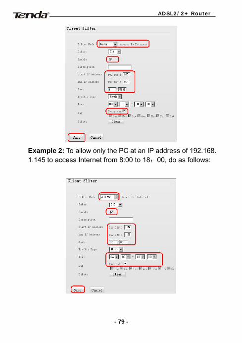
Example 1: To prohibit PCs within the IP address range of
192.168.1.100--192.168.1.150 from accessing Internet, do as follows:
- 78 -
ADSL2/2+ Router
Example 2: To allow only the PC at an IP address of 192.168. 1.145 to access Internet from 8:00 to 18:00, do as follows:
- 79 -
ADSL2/2+ Router
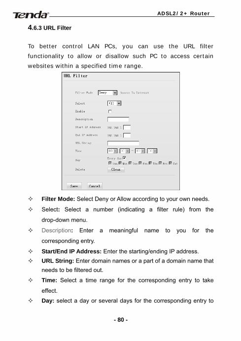
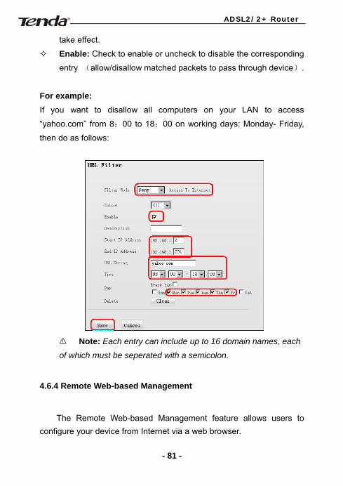
4.6.3 URL Filter
To better control LAN PCs, you can use the URL filter
functionality to allow or disallow such PC to access certain
websites within a specified time range.
Filter Mode: Select Deny or Allow according to your own needs.
Select: Select a number (indicating a filter rule) from the
drop-down menu.
Description: Enter a meaningful name to you for the
corresponding entry.
Start/End IP Address: Enter the starting/ending IP address. URL String: Enter domain names or a part of a domain name that
needs to be filtered out.
Time: Select a time range for the corresponding entry to take
effect.
Day: select a day or several days for the corresponding entry to
- 80 -
ADSL2/2+ Router
take effect.
Enable: Check to enable or uncheck to disable the corresponding
entry (allow/disallow matched packets to pass through device).
For example: If you want to disallow all computers on your LAN to access
“yahoo.com” from 8:00 to 18:00 on working days: Monday- Friday,
then do as follows:
Note: Each entry can include up to 16 domain names, each
of which must be seperated with a semicolon.
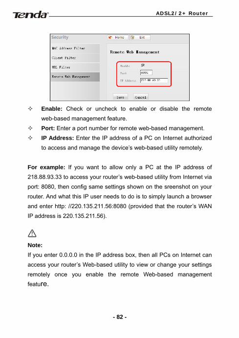
4.6.4 Remote Web-based Management
The Remote Web-based Management feature allows users to configure your device from Internet via a web browser.
- 81 -
ADSL2/2+ Router
Enable: Check or uncheck to enable or disable the remote
web-based management feature.
Port: Enter a port number for remote web-based management.
IP Address: Enter the IP address of a PC on Internet authorized
to access and manage the device’s web-based utility remotely.
For example: If you want to allow only a PC at the IP address of
218.88.93.33 to access your router’s web-based utility from Internet via
port: 8080, then config same settings shown on the sreenshot on your
router. And what this IP user needs to do is to simply launch a browser
and enter http: //220.135.211.56:8080 (provided that the router’s WAN
IP address is 220.135.211.56).
Note: If you enter 0.0.0.0 in the IP address box, then all PCs on Internet can
access your router’s Web-based utility to view or change your settings
remotely once you enable the remote Web-based management
feature.
- 82 -
ADSL2/2+ Router
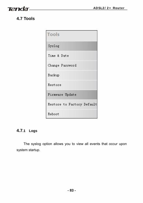
4.7 Tools
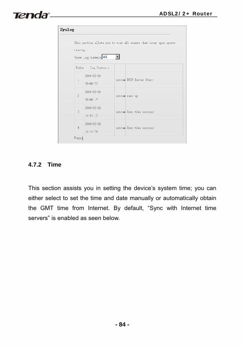
4.7.1 Logs
The syslog option allows you to view all events that occur upon
system startup.
- 83 -
ADSL2/2+ Router
4.7.2 Time
This section assists you in setting the device’s system time; you can
either select to set the time and date manually or automatically obtain
the GMT time from Internet. By default, “Sync with Internet time
servers” is enabled as seen below.
- 84 -

ADSL2/2+ Router
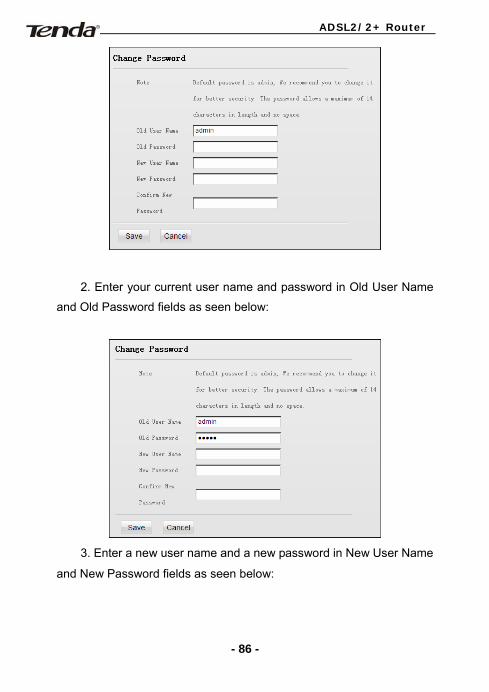
4.7.3 Change Password/User Name
This section allows you to change login password/user name for
accessing device web manager. Both login password and user name
are preset to “admin” by default. To change either, do as follows:
1. Click “Change Password” to enter the interface below:
- 85 -
ADSL2/2+ Router
2. Enter your current user name and password in Old User Name
and Old Password fields as seen below:
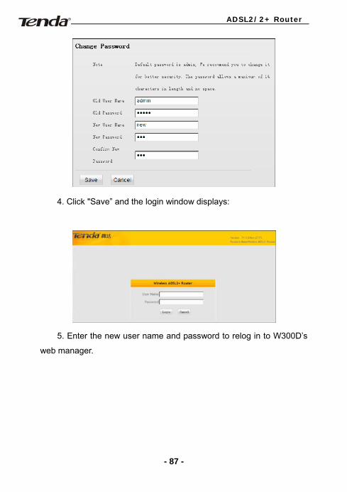
3. Enter a new user name and a new password in New User Name
and New Password fields as seen below:
- 86 -
ADSL2/2+ Router
4. Click "Save” and the login window displays:
5. Enter the new user name and password to relog in to W300D’s
web manager.
- 87 -
ADSL2/2+ Router
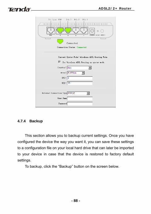
4.7.4 Backup
This section allows you to backup current settings. Once you have
configured the device the way you want it, you can save these settings
to a configuration file on your local hard drive that can later be imported
to your device in case that the device is restored to factory default
settings.
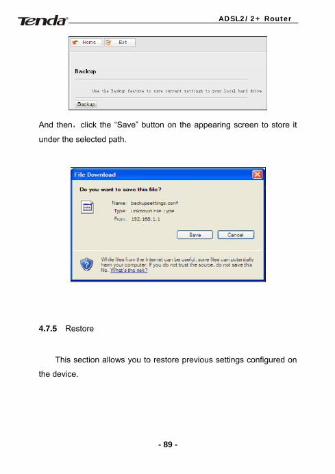
To backup, click the “Backup” button on the screen below.
- 88 -
ADSL2/2+ Router
And then,click the “Save” button on the appearing screen to store it
under the selected path.
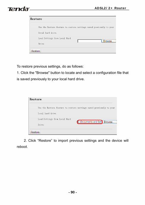
4.7.5 Restore
This section allows you to restore previous settings configured on
the device.
- 89 -
ADSL2/2+ Router
To restore previous settings, do as follows:
1. Click the "Browse" button to locate and select a configuration file that
is saved previously to your local hard drive.
2. Click “Restore” to import previous settings and the device will
reboot.
- 90 -
ADSL2/2+ Router
4.7.6 Firmware Upgrade
Firmware upgrade is released periodically to improve the
functionality of your device and also to add new features. If you run into
a problem with a specific feature of the device, log on to our website
(www.tenda.cn or www.tendacn.com)to download the latest firmware
to update your device.
- 91 -
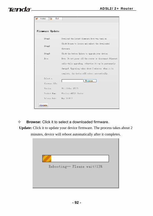
ADSL2/2+ Router
Browse: Click it to select a downloaded firmware. Update: Click it to update your device firmware. The process takes about 2
minutes, device will reboot automatically after it completes.
- 92 -
ADSL2/2+ Router
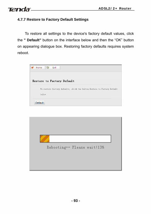
4.7.7 Restore to Factory Default Settings
To restore all settings to the device's factory default values, click
the " Default” button on the interface below and then the “OK” button
on appearing dialogue box. Restoring factory defaults requires system
reboot.
- 93 -
ADSL2/2+ Router
A ppendix 1
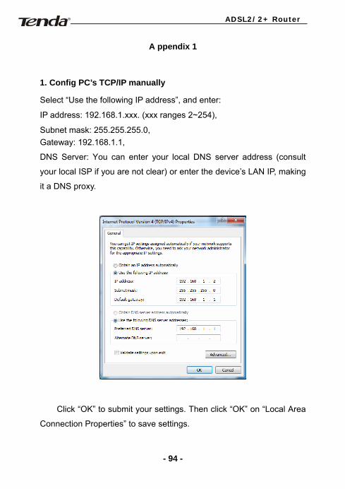
1. Config PC’s TCP/IP manually
Select “Use the following IP address”, and enter:
IP address: 192.168.1.xxx. (xxx ranges 2~254),
Subnet mask: 255.255.255.0, Gateway: 192.168.1.1,
DNS Server: You can enter your local DNS server address (consult
your local ISP if you are not clear) or enter the device’s LAN IP, making
it a DNS proxy.
Click “OK” to submit your settings. Then click “OK” on “Local Area
Connection Properties” to save settings.
- 94 -
ADSL2/2+ Router
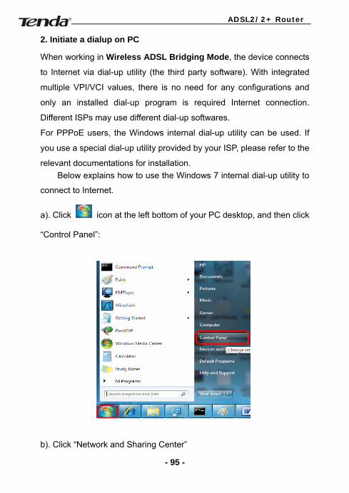
2. Initiate a dialup on PC
When working in Wireless ADSL Bridging Mode, the device connects
to Internet via dial-up utility (the third party software). With integrated
multiple VPI/VCI values, there is no need for any configurations and
only an installed dial-up program is required Internet connection.
Different ISPs may use different dial-up softwares.
For PPPoE users, the Windows internal dial-up utility can be used. If
you use a special dial-up utility provided by your ISP, please refer to the
relevant documentations for installation. Below explains how to use the Windows 7 internal dial-up utility to
connect to Internet.
a). Click icon at the left bottom of your PC desktop, and then click
“Control Panel”:
b). Click “Network and Sharing Center”
- 95 -
ADSL2/2+ Router
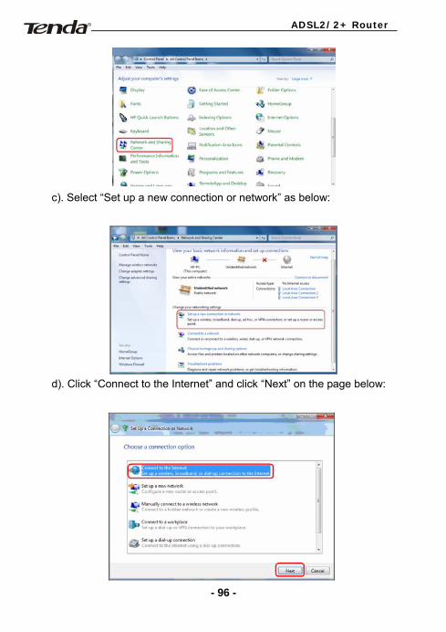
c). Select “Set up a new connection or network” as below:
d). Click “Connect to the Internet” and click “Next” on the page below:
- 96 -
ADSL2/2+ Router
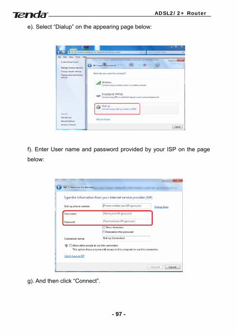
e). Select “Dialup” on the appearing page below:
f). Enter User name and password provided by your ISP on the page
below:
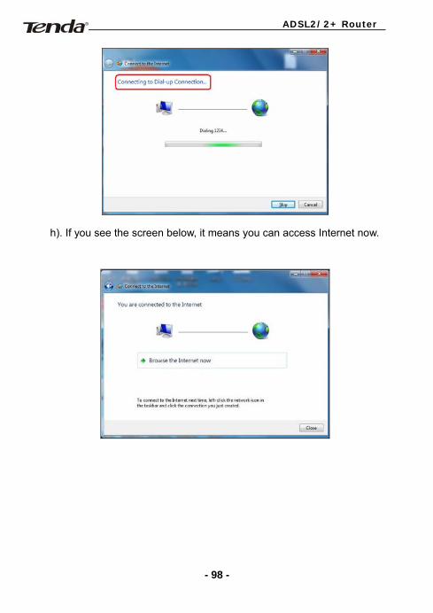
g). And then click “Connect”.
- 97 -
ADSL2/2+ Router
h). If you see the screen below, it means you can access Internet now.
- 98 -
ADSL2/2+ Router
Appendix 2
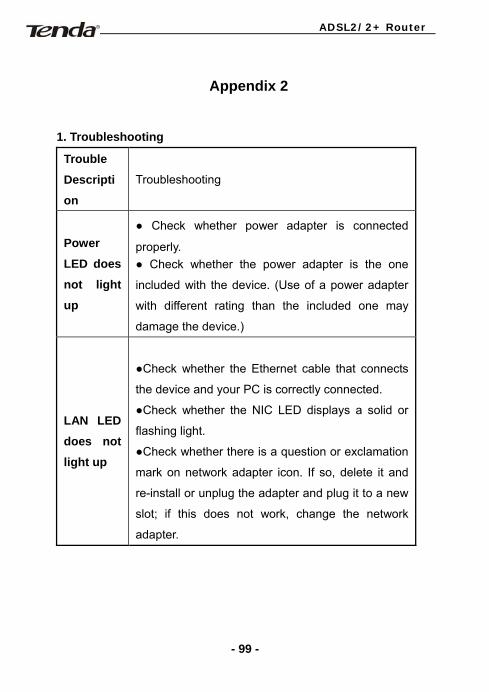
1. Troubleshooting
Trouble
Descripti
on
Troubleshooting
Power
LED does
not light
up
● Check whether power adapter is connected
properly. ● Check whether the power adapter is the one
included with the device. (Use of a power adapter
with different rating than the included one may
damage the device.)
LAN LED
does not
light up
●Check whether the Ethernet cable that connects
the device and your PC is correctly connected.
●Check whether the NIC LED displays a solid or
flashing light.
●Check whether there is a question or exclamation
mark on network adapter icon. If so, delete it and
re-install or unplug the adapter and plug it to a new
slot; if this does not work, change the network
adapter.
- 99 -
ADSL2/2+ Router
Can’t
access
the
Internet
● Make sure you are not confronting the above
troubles.
● Make sure dial-up utility is installed and correctly
configured.
● Make sure the user name and password entered
are correct.
● If the dial-up is successful, make sure the IE
proxy server is configured properly. ● Open several web pages to see if they can be
displayed.
2. Verify connectivity between the device and your PC
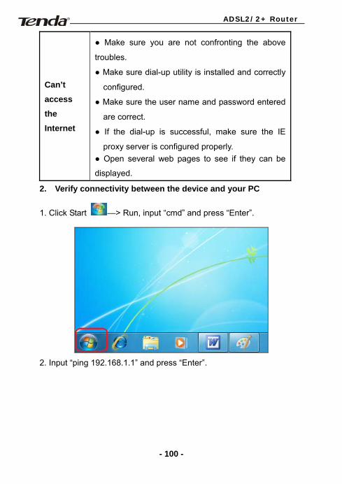
1. Click Start —> Run, input “cmd” and press “Enter”.
2. Input “ping 192.168.1.1” and press “Enter”.
- 100 -
ADSL2/2+ Router
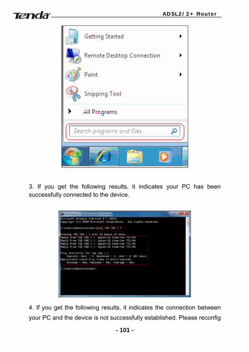
3. If you get the following results, it indicates your PC has been successfully connected to the device.
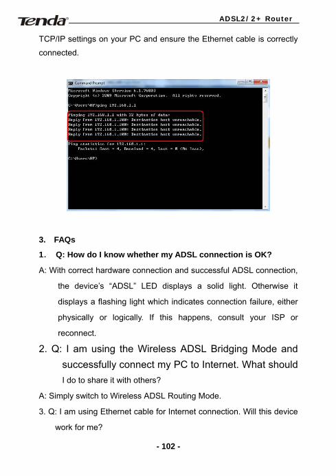
4. If you get the following results, it indicates the connection between
your PC and the device is not successfully established. Please reconfig
- 101 -
ADSL2/2+ Router
TCP/IP settings on your PC and ensure the Ethernet cable is correctly
connected.
3. FAQs
1. Q: How do I know whether my ADSL connection is OK?
A: With correct hardware connection and successful ADSL connection,
the device’s “ADSL” LED displays a solid light. Otherwise it
displays a flashing light which indicates connection failure, either
physically or logically. If this happens, consult your ISP or
reconnect.
2. Q: I am using the Wireless ADSL Bridging Mode and successfully connect my PC to Internet. What should I do to share it with others?
A: Simply switch to Wireless ADSL Routing Mode.
3. Q: I am using Ethernet cable for Internet connection. Will this device
work for me?
- 102 -
ADSL2/2+ Router
A: Yes. Simply connect your Ethernet cable to LAN port 4 on the
device and follow instructions in section 4.3.2 to config it for
Internet connection.
4. Q: I tried whatever I can but still can not achieve a successful ADSL
Internet connection. What shoul I do?
A: First, verify that you entered the correct user name and
password.Then consult your local ISP for latest VPI/VCI values
and enter them manually on your device as your local VPI/VCI
values may have changed or are different from those integrated in
the device.
5. Q: I have been enjoying Internet surfing using the device for quite a
period of time. However, all of a sudden, it does not work now.What
should I do?
A: Check connectivity between your PC, device and Internet. Contact
your ISP to see whether your Internet service is still available.If
problem exists in the device, contact Tenda technical support for
help.
6. Q: I’m an ADSL user, but sometimes I cannot access the Internet, why? A: ADSL utilizes frequencies that are not used by a voice telephone call.
A splitter, or DSL filter, allows a single telephone connection to be
used for both ADSL service and voice calls at the same time. Any
device added to the connection between telephone exchange and
DSL filter, over which ADSL is distributed, would adversely affect
data transmission. So it is advisable not to add any devices
between the telephone exchange and DSL filter.
7. Q: I applied for ADSL service. Will an ADSL2+ modem work for me?
A: Yes. The ADSL2+ is backward compatible with the existing ADSL
service. With an ADSL2+ modem, it won’t bother you if your ISP
- 103 -
ADSL2/2+ Router
upgrades the network to ADSL2+ one day. Plus, there is almost no
difference in the prices between an ADSL2+ modem and an
ADSL2 modem. 8. Q: What is VPI/VCI?
A: VPI is short for Virtual Path Identifier and VCI is short for Virtual
Channel Identifier. Both are used by DSLAM to identify an ATM
terminal (ADSL connection). Different ISP may use different
VPI/VCI values. Consult your ISP if you are not clear.
9. Q: What parameters do I need from my ISP for the ADSL Internet
connection?
A: You will need the following info: connection protocol, user name,
password, VPI/VCI values and encapsulation type.
10. Q: How do I reset my device?
A: 1). Power up the device
2). Keep pressing the Reset button located on the device fro over
8 seconds and then release it. The device shall restart
automatically and settings are successfully restored to factory
defaults.
11. Q: How do I obtain a correct DNS server address?
A: 1). Contact your ISP for the DNS server address.
2). Go to Status on web utility to view and note down the DNS
server address when device is successfully connected to Internet.
12. Q: What factors may adversely affect wireless signal? Maximum wireless signal rate is derived from IEEE Standard 802.11g
and 802.11n specifications. Actual data throughput will vary due to
factors below:
1. Network conditions such as volume of network traffic lower actual
data throughput.
2. Environmental factors such as building materials and construction
- 104 -
ADSL2/2+ Router
will adversely affect wireless signal range.
3. Electronic Interference: Wireless network devices commonly use the
2.4 GHz radio wave frequency to transmit and receive data. When other
nearby electronic devices such as cell phones, radio transmitters and
microwaves emit this frequency, they interfere with the network's signal
transmission.
4. Physical obstacles such as metal, thick concrete walls also cause
wireless signal loss. When radio waves pass through a medium, signal
degradation occurs because the object absorbs some of the signal or
scatters it. Thicker objects absorb a larger portion of the wireless signal.
5. Bad weather such as fog and heavy rain increases wireless signal
attenuation.
13. How do I improve the wireless data transmission? A: 1. Place the device in a position featuring the following: a). relatively
high so that wireless signal can radiate downward; with least
obstacles around.
b). with least walls that wireless signal must penetrate. It is better if
the device is visible to the wireless clients.
2. Select a channel with least interference. Note: It is advisable to
use a channel that is over 5 channels away from that used by any
existing wireless devices nearby.
3. Keep the device far away from electrical appliances, avoiding
any potential interference.
3. Change for a better antenna, if the device is equipped with a
detachable antenna.
- 105 -
ADSL2/2+ Router
Appendix 3 EMC Statement
CE Mark Warning
This is a Class B product In a domestic environment,this product may cause
radio interference,in which case the user may be required to take adequate
measures.This device complies with EU 1999/5/EC.
NOTE:(1)The manufacturer is not responsible for any radio or TV
interference caused by unauthorized modifications to this equipment.(2) To
avoid unnecessary radiation interference, it is recommended to use a shielded
RJ45 cable
FCC Statement
This device complies with Part 15 of the FCC Rules. Operation is subject to
the following two conditions: (1) This device may not cause harmful
- 106 -
ADSL2/2+ Router
interference, and (2) this device must accept any interference received,
including interference that may cause undesired operation.
This equipment has been tested and found to comply with the limits for a
Class B digital device, pursuant to Part 15 of the FCC Rules. These limits
are designed to provide reasonable protection against harmful interference in a
residential installation. This equipment generates, uses and can radiate radio
frequency energy and, if not installed and used in accordance with the
instructions, may cause harmful interference to radio communications.
However, there is no guarantee that interference will not occur in a particular
installation. If this equipment does cause harmful interference to radio or
television reception, which can be determined by turning the equipment off
and on, the user is encouraged to try to correct the interference by one of the
following measures:
- Reorient or relocate the receiving antenna.
- Increase the separation between the equipment and receiver.
- Connect the equipment into an outlet on a circuit different from that
to which the receiver is connected.
- Consult the dealer or an experienced radio/TV technician for help.
- 107 -
ADSL2/2+ Router
FCC Caution: Any changes or modifications not expressly approved by the
party responsible for compliance could void the user's authority to operate this
equipment.
This transmitter must not be co-located or operating in conjunction with any
other antenna or transmitter.
The manufacturer is not responsible for any radio or TV interference caused
by unauthorized modifications to this equipment.
Radiation Exposure Statement
This equipment complies with FCC radiation exposure limits set forth for an
uncontrolled environment. This equipment should be installed and operated
with minimum distance 20cm between the radiator & your body.
NOTE:(1)The manufacturer is not responsible for any radio or TV
interference caused by unauthorized modifications to this equipment.(2) To
avoid unnecessary radiation interference, it is recommended to use a shielded
RJ45 cable
- 108 -
ADSL2/2+ Router
Contact Information
If you have any poblem, please contact our customer service or
technical support
Technical Support Toll Free: 1-800-570-5892 (For USA only)
Tel: +86 (755) 2344 2820
Email: [email protected]
Headquarter Shenzhen: Add:Tenda Industrial Zone,No.34-1 Shilong Road,Shiyan
Town,Baoan District,Shenzhen,China. 518108
Tel: (86)755-27657180 Fax: (86)755-27657178
Email: [email protected]
Technical Support: [email protected]
Or visit our website at: http://www.tenda.cn
- 109 -