Embed Size (px)
Citation preview

Ethernet / LAN
Extension
ADSL2+ / VDSL Solutions
(For Copper, Fiber, & Wireless)
Power Over Ethernet (PoE) &
FIBER (PoF)
Telephone & Demark Extension
(T1, T3, E1, DS1, DS3, POTS, FXS &FXO)
Channel Banks
Industrial Modems
Serial Data & Modem Extension
(Over Copper, Fiber, & Wireless)
Industrial
Servers & Switches
Call 1.888.4WANLAN www.dataconnectus.com
INDUSTRIALINDUSTRIAL NETWORKNETWORK
SOLUTIONSSOLUTIONS
2
2
Headquartered in Olney, Maryland, near Washington, DC, Data Connect manufactures reliable networking and com-munications products. We have offices serving major metropoli-tan areas throughout the country as well as substantial interna-tional penetration with distributors around the world. Specializ-
ing in networking and communications technologies, Data Connect provides a wide range of solutions to wire-line and wireless applications in data, voice and video transmission. Data Connect specializes in industrial grade, temperature rated, and hardened commu-nications solutions. We produce a wide range of industrial Ethernet, industrial wireless, and industrial modem products used extensively in both trailing-edge and leading-edge ap-plications. Data Connect is well equipped to help businesses, VARs, and systems integra-tors looking for reliable networking solutions. Ask Data Connect for help in both your existing legacy network applications and in your new networks using state-of-the-art in-tegrated solutions. SYSTEMS SOLUTIONS: All Data Connect recommendations are made with system integrity in mind. We may ask a few more questions about your application, but this is done to ensure the right solution for your requirement. MAINTENANCE AND REPAIR SERVICES: Data Connect offers repair services, warranty enhancements, in-stallation services, site surveys, and consulting services for wireless, wire-line, voice, data, video, and converged network products and applications. We offer fixed price maintenance contracts for a wide range of equipment. Maintenance contracts and exclusive programs help you control downtime and budgets. Maintenance contracts and exclusive money saving programs can lower your costs while saving you time. TOTAL PREMISE SOLUTIONS: We are able to recommend, design, deliver, implement and service a broad range of network and connectivity solutions within specific and unique environments. In addition to supplying premise equipment and wiring, Data Connect provides a full range of data and voice premise services. These ser-vices include custom patch cabling, wiring upgrades, dressing of existing cabling and cabinets and complete com-puter room relocations-all within applicable code and cutover deadlines EXPRESS DELIVERY: In addition to traditional freight services, Data Connect provides personal delivery for emergency requirements whenever possible. Orders for stock items are rushed and filled the day they are plac ed. Special order and custom terms are expedited to meet customer deadlines.
GUARANTEE: All standard stock products are backed by Data Connect's reliability guarantee. Any DOA unit will be exchanged from Data Connect's stock for an immediate brand new replacement unit. In addition, if the item ordered does not completely satisfy your requirement, simply notify us within 15 days of purchase and we will swap out the unit for the correct product. Most Data Connect products come with 1-year, 2-year, or 5-year as well as lifetime warranties. WARRANTIES: Please ask about extended warranty options. NO SALES ARE FINAL: Since NO SALES ARE FINAL, you can return any item that you have purchased from DATA CONNECT. Returns of items after 30 days from the date of shipment should, but may not necessarily, result in a credit. The determination of the restocking fee to be applied will be made by the DATA CONNECT RMA Department based upon the age of the unit, its condition, the unit’s state of obsolescence, product.

3
3
TABLE OF CONTENTS
ETHERNET / LAN EXTENSION COPPER ETHERNET EXTENSION Extend Ethernet Circuits to 6,232ft 6 Minus 40 to Plus 75 Degrees Cel-sius
7
NEMA TS1 TS2 Environment Re-quirements
8
Four Ethernet Devices over 2-Wire 10 5 Mbps at 1.8 Miles 11 11 Mbps at 1.8 Miles 11 22 Mbps at 1.8 Miles 11 100 Mbps Down-stream / Up-stream
12
COAX ETHERNET EXTENSION Extend Ethernet Circuits over COAX
15
FIBER ETHERNET EXTENSION Extend Ethernet Circuits over Fiber 16
WIRELESS ETHERNET EXTENSION 500 Mbps to 500 ft 17 300 Mbps to 500 ft / 5 mbps at 5Miles
19
VDSL2 & ADSL2+ SOLUTIONS VDSL2 SOLUTIONS 1-Port VDSL2 Bridge Modem 24 4-Port VDSL2 Bridge Modem 27 4-Port VDSL2 Modem Router 28 4-Port VDSL2 Wireless N Router 30
VDSL DSLAM 8-Port VDSL SNMP Switch 2-SFP 32 24-Port VDSL DSLAM 2-SFP 35 24-Port VDSL DSLAM 2-SFP 48VDC 35 48-Port VDSL DSLAM 2-SFP 35 48-Port VDSL DSLAM 2-SFP 48VDC 35
ADSL2+ SOLUTIONS 1-Port ADSL2+ Bridge Modem 38 1-Port ADSL2+ Modem Router 39 4-Port ADSL2+ 802.11G Router 40 48-Port ADSL2+ DSLAM 42 24-Port ADSL2+ DSLAM 44 DSL-Filter 46 DSL-Splitter 47
POWER OVER ETHERNET (POE) & FIBER (POF)
COPPER POWER OVER ETHERNET (POE) 48VDC POE 10/100 50 48VDC POE 10/100/1000 51 Analog Telephone Adapter 52 48VDC POE 12-Port Hub 54
FIBER POWER OVER ETHERNET (POF) 48VDC (POF) 10/100/1000 55
POE SURGE SUPPRESSOR 60V POE Surge Suppression 56
DIAL LINE & DEMARC EXTENSION TELEPHONE EXTENSION/ FXS, FXO, & POTS Fiber Telephone Station Extender 60
T1, E1, DS1, T3 & DS3 EXTENSION Copper T1/E1/DS1 Extender 61 Fiber T1/E1/DS1 Extender 62 Quad Fiber T1/E1 63 Fiber T3/E3/DS3 Extender 64 RM20UI Chassis Series 65
CHANNEL BANKS D4 CHANNEL BANK PAGES 69-71 Selectable FXO/FXS Channel Bank 70
INDUSTRIAL MODEMS V.92 &V.90 56KBPS 74-79
V.34.BIS 33.6KBPS 80-89
V.34 28.8KBPS 90-95
19.2 & 9.6 HFP, V.29 & V.27 1.2 - 19.2KBPS 96-99 V.32BIS 14.4KBPS 100-117
V.22 2.4KBPS 118-127
V.23 1.2KBPS 128-129
BELL202T,R38 MULTIPROTOCOL 0-1800BPS 130-137
SERIAL DATA & MODEM EXTENSION SERIAL DATA COPPER MODEM Industrial Grade 202T 1.2K Series 141 Industrial Grade 202T R38 0-1-2K 142 MIU 202T 1.2K Series 143 202TE-037-4 1.2K Series 147 Industrial Grade 9.6K Series 148 MIU 9.6FPD Series 150 MIU14.4L Series 154 Industrial Grade 19.2K Series 159 V.3600LP Series 160 V.3600UI Series 162
WIRELESS SERIAL DATA EXTENSION SWM910A Series 163
SERIAL DATA FIBER EXTENSION Low Speed Serial Fiber Modem 164 High Speed Serial Fiber Modem 165 Super High Speed Serial Fiber Mo-dem
165
INDUSTRAIL SERVERS & SWITCHES ETHERNET SERIAL SERVERS
1-2 Port Serial to Ethernet Con- 168
4-Port Serial to Ethernet Converter 169
INDUSTRIAL GRADE SWITCHES Industrial Advance 5-Port Switch 170 Industrial Advance 8-Port Switch 171
4
4
MODEL MAX. DIS-
TANCE MAX.
SPEED DISTANCE AT MAX. SPEED
RACK MOUNT
DIN MOUNT PHOTO PAGE
2178EE 6,232 FEET
(Copper Wire)
50MBPS 900 FEET YES YES 6
2178HEE (Hardened)
6,232 FEET (Copper
Wire) 50MBPS 900 FEET YES YES 7
2178MDEE (Multi-Drop)
6,232 FEET PER DROP
(Copper Wire)
50 MBPS 900 FEET YES YES 8
2178MPEE (Multi-Point)
6,232 FEET (Copper
Wire) 50 MBPS 900 FEET YES YES 10
2178LRE-1 (Long Reach)
4.9 MILES (Copper
Wire) 5 MBPS 1.8 MILES NO NO 11
2178LRE-2 (Long Reach)
4.9 MILES (Copper
Wire) 11 MBPS 1.8 MILES NO NO 11
2178LRE-4 (Long Reach)
4.9 MILES (Copper
Wire) 22 MBPS 1.8 MILES NO NO 11
2178HSEE (High Speed)
4,593 FEET (Copper
Wire)
100 MBPS
900 FEET YES NO 12
2178CEE (Coax)
7,784 FEET (Coax or
Telephone Wire)
100 MBPS
655 FEET NO NO 15
2178FEE (Fiber)
74.5 MILES (MM, SM, or WDM Fiber)
100 MBPS UNLIMITED NO NO 16
2178WEE (Wireless)
5,000 FEET (Wireless N)
150 MBPS
900 FEET NO NO 17
2178HPWEE (High Power
Wireless)
25 MILES LINE OF
SITE (LOS) (Wireless N & HP Antenna)
300 MBPS
.5 MILES NO NO 19
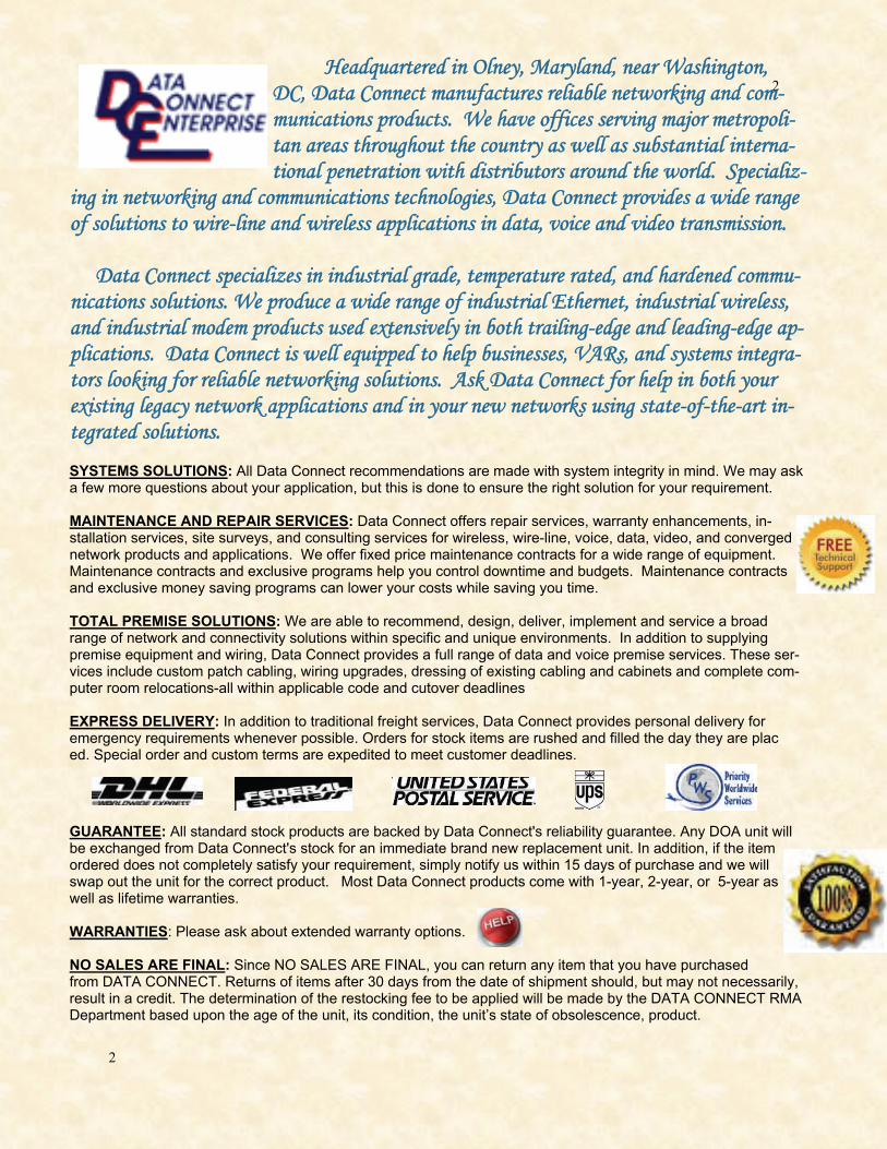
INDUSTRIAL SOLUTIONS ETHERNET EXTENDERS NETWORK ANYWHERE ETHERNET EXTENDER DISTANCE CHECK LIST

5
5
Ethernet extension allows users to expand their Ethernet connections be-yond the 328-foot (100-meter) Ethernet distance limitations. Ethernet extenders can establish long-range, high-speed data communication links between geo-graphically separated LANs or LAN devices. Ethernet extenders are often em-ployed to connect workgroups on different floors within a building. One benefit of Ethernet extenders is they can eliminate the need for install-ing expensive Switches and CAT5 cable. Ethernet extenders can use fiber-optic, coax, wireless, or copper twisted-pair cables to transparently send pack-ets at full-line rate to a peered LAN up to twenty-five miles away. While net-works typically deploy Ethernet extenders within a limited geographical area, this area need not be limited to one building. Ethernet extenders can create ef-fective bridged-Ethernet connections across streets or over a college or enter-prise campus and between Ethernet LANs up to twenty-five miles apart. Ethernet extenders are cost-effective alternatives to more complicated and pricey wiring installations such as CAT5 cable. Ethernet extenders are plug-and-play devices that you can install quickly to take advantage of existing cop-per twisted-pair network infrastructure. Depending on the required data rate, some Wireless Ethernet extender models can increase the distance of an Ethernet link up to twenty-five miles with Line Of Site (LOS). At Data Connect, we offer a wide range of award-winning Ethernet Extend-ers to serve your networking needs, including copper, coax, fiber, and wireless models. Our auto-rate adaptation feature ensures the highest speed possible across great distances. Unlike many LAN extenders, Data Connect extenders with auto-rate adaptation can be set for multiple data rates and require no diffi-cult configuration when connecting to LANs at different distances.
The Technology
ETHERNET / LAN EXTENSION In this Section Extend Ethernet Circuits up to 6,232 Feet Pg 6 -40 to +75 Degrees Celsius Pg 7 NEMA TS1 & TS2 Environmental Requirements Pg 8 Up to 4 Ethernet Devices over 2-Wire Pg 10 5 Mbps at 1.8 Miles Pg 11 11 Mbps at 1.8 Miles Pg 11 22 Mbps at 1.8 Miles Pg 11 100 Mbps Downstream / Upstream Pg 12 Extend Ethernet Circuits over Coax Pg 15 Extend Ethernet Circuits over Fiber Pg 16 Extend Ethernet Circuits over Wireless 100 Mbps to 500 ft Pg 17 Extend Ethernet Circuits over Wireless 5 Mbps at 25 Miles Pg 19
INDUSTRIAL SOLUTIONS ETHERNET EXTENDERS NETWORK ANYWHERE IN THIS SECTION & THE TECHNOLOGY

6
6
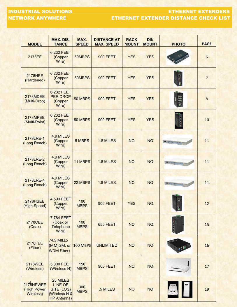
The 2178EE is a point-to-point Industrial Ethernet Extender that efficiently extends 10/100 Ethernet circuits up to 6,232 feet and supports speeds from 1Mbps to 50Mbps using existing straight pair copper wire. The 2178EE will allow Ethernet connectivity in existing facilities without pulling extra cable. This is the perfect solution to Ethernet on the factory floor where systems have been upgraded from slower serial communica-tions to Ethernet networking. Applications are endless; all that is needed is access to copper pairs. Installation is easy with a single switch setting; one end is set for local and the other re-mote. The 2178EE is used in pairs to extend Ethernet connec-tivity over existing voice grade copper wire.
SPECIFICATIONS
Technology Standards: IEEE802.3 10Base-T, IEEE802.3u 100Base-TX, IEEE802.3x, Ethernet over VDSL Protocols: Transparent to higher layer protocols Processing Type: Half-duplex back-pressure and IEEE802.3x Full-duplex flow control Power Input: Input Voltage: 12VDC Power Consumption: 2.4W Max._ 0.2A@12VDC Mechanical Casing: Aluminum case Dimensions: 80.3mm (W) x 109.2mm (D) x 23.8mm (H); (3.16" (W) x 4.30" (D) x 0.94" (H)) Weight: 150g (0.33lb.) Installation: DIN-Rail, Wall Mounting Interface Ethernet Port: Port: One RJ-45 port, 10/100Base-TX Full/Half-duplex, Auto-Negotiation, Auto-MDI/MDIX Speed: 10/100Mbps Distance: 100meters (328ft.) Cable: 10Base-T: UTP CAT. 3, 4, 5 (2-pair wire) & 100Base-TX: UTP CAT. 5 (2-pair wire) Ethernet Extension Port Port: One RJ-11 Port Speed: 1/3/5/10/15/20/25/30/40/50mbps Distance: 1900meters (6,232ft.) Cable: Telephone line 24 AWG (0.5mm diameter, 1-pair wire) or larger DIP Switch: One DIP switch: Local (CO) or Remote (CPE) LED Indicators: Per Unit: Power Status (Power), 10/100TX: Link/Activity, Full-duplex & Line: Error, Link, Local, Remote Environment Operating Temperature: -20°C to 60°C (-4°F to 140°F) Storage Temperature: -20°C to 70°C (-4°F to 158°F) Ambient Relative Humidity: 5% to 95% (non-condensing)
DISTANCE CHART NOTE: All speed selections are Symmetrical on the DSL and Full-duplex on the Ethernet. LED SPEED DISTANCE 1 Green 1Mbps 1,900m (6,232 ft) Amber 3Mbps 1,800m (5,904 ft) 2 Green 5Mbps 1,600m (5,249 ft) Amber 10Mbps 1,400m (4,593 ft) 3 Green 15Mbps 1,200m (3,936 ft) Amber 20Mbps 1,000m (3,280 ft) 4 Green 25Mbps 800m (2,624 ft) Amber 30Mbps 700m (2,296 ft) 4&2 Amber 40Mbps 600m (1,968 ft) 4&3 Amber 50Mbps 300m (984 ft)
DCE 2178EE
FEATURES
Operates transparent to higher layer protocols such as TCP/IP
Ethernet Port: 10/100Mbps-Full/Half-duplex, Auto-Negotiation, Auto-MDI/MDIX
Ethernet Extender (RJ-11) Port: Symmetrical on the VDSL
High speed Full-duplex 50Mbps communications link over existing cop-per facilities
Support DIP switch to select Local or Remote side
Ten speeds with speed indicator LEDs on top of unit,
Up to 50 Mbps @ about 300 meters (984 ft) & down to 1 Mbps @ about 1,900 meters (6,232 ft)
-20°C to 60°C (-4°F to 140°F) operating temperature range
Industrial Hardened aluminum case
Supports DIN-Rail, Wall Mounting installation or expansion use with our media converter chassis system
ODERING INFORMATION DCE/2178EE Data Connect 10/100Base-TX Industrial Ethernet Extender DCE/2178EE-2PK Data Connect 10/100Base-TX Industrial Ethernet Extender, 2-Pack DCE/2178EE-DIN Data Connect DIN rail mount kit
DATA CONNECT ENTERPRISE 3405 OLANDWOOD CT OLNEY, MD 20832 USA PHONE: 301.924.7400 EXT 17 FAX: 301.924.7403 www.data-connect.com
APPLICATION
INDUSTRIAL SOLUTIONS ETHERNET EXTENDERS NETWORK ANYWHERE COPPER ETHERNET EXTENDERS

7
7
INDUSTRIAL SOLTIONS ETHERNET EXTENDERS NETWORK ANYWHERE HARDENED COPPER ETHERNET
DATA CONNECT ENTERPRISE 3405 OLANDWOOD CT OLNEY, MD 20832 USA PHONE: 301.924.7400 EXT 17 FAX: 301.924.7403 www.data-connect.com
The Data Connect 2178HEE is a point-to-point Industrial Ethernet Extender designed to operate in harsh environ-ments that efficiently extends 10/100 Ethernet circuits up to 6,232 feet and supports speeds from 1Mbps to 50Mbps using existing crossover pair copper wire. The 2178HEE function sat temperatures ranging from -40°C to 75°C (-40°F to 167°F) and is tested for functional op-eration @ -40°C to 85°C (-40°F to 185°F). The 2178HEE-will allow Ethernet connectivity in existing facilities with-out pulling extra cable. This is the perfect solution to Ethernet on the factory floor where systems have been upgraded from slower serial communications to Ethernet networking.
SPECIFICATIONS
Technology Standards: IEEE802.3 10Base-T, IEEE802.3u 100Base-TX, IEEE802.3x, Ethernet over VDSL Protocols: Transparent to higher layer protocols Processing Type: Half-duplex back-pressure and IEEE802.3x Full-duplex flow control Power Input: Input Voltage: 12-30VDC Power Consumption: 2.4W Max._ 0.2A@12VDC Mechanical Casing: Aluminum case Dimensions: 50mm (W) x 110mm (D) x 135mm (H); (1.97" (W) x 4.33" (D) x 5.31" (H)) Weight: .8kg (1076lbs.) Installation: DIN-Rail, Wall Mounting Interface Ethernet Port: Port: One RJ-45 port, 10/100Base-TX Full/Half-duplex, Auto-Negotiation, Auto-MDI/MDIX Speed: 10/100Mbps Distance: 100meters (328ft.) Cable: 10Base-T: UTP CAT. 3, 4, 5 (2-pair wire) & 100Base-TX: UTP CAT. 5 (2-pair wire) Ethernet Extension Port Port: One RJ-11 Port Speed: 1/3/5/10/15/20/25/30/40/50mbps Distance: 1900meters (6,232ft.) Cable: Telephone line 24 AWG (0.5mm diameter, 1-pair wire) or larger DIP Switch: One DIP switch: Local (CO) or Remote (CPE) LED Indicators: Per Unit: Power Status (Power), 10/100TX: Link/Activity, Full-duplex & Line: Error, Link, Local, Remote Environment Operating Temperature: -20°C to 60°C (-4°F to 140°F) Storage Temperature: -20°C to 70°C (-4°F to 158°F) Ambient Relative Humidity: 5% to 95% (non-condensing)
DCE 2178HEE
FEATURES
Complies with NEMA TS1 & TS2 Environmental require-ments for Traffic control equipment
Complies with IEC61000-6-2 EMC Generic standard immu-nity for Industrial environment
Operates transparent to higher layer protocols such as TCP/IP Support DIP switch to select Local or Remote side
Redundant power inputs with Terminal Block and DC Jack
Ten speeds with speed indicator LEDs on top of unit
Ethernet Port: 10/100Mbps-Full/Half-duplex, Auto-Negotiation, Auto-MDI/MDIX
Ethernet Extender(RJ-11 and Terminal Block) Port
Hardened aluminum case
Supports DIN-Rail or Panel Mounting installation
ORDERING INFORMATION
2178HEE 10/100Base-TX Industrial Hardened Ethernet Extender 2178HEE-2PK 10/100Base-TX Industrial Hardened Ethernet Extender. 2-Pack 2178HEE-DIN DIN Rail Mount Kit
APPLICATION
REGULATORY APPROVALS
Regulatory Approvals ISO: Manufactured in an ISO9001 facility Safety: UL60950-1, EN60950-1, IEC60950-1EMI: FCC Part 15, Class A EN61000-6-3 EN55022 EN61000-3-2 EN61000-3-3EMS: EN61000-6-2 EN61000-4-2 (ESD Standards) Contact: + / - 4KV; Criteria B Air: + / - 8KV; Criteria B EN61000-4-3 (Radiated RFI Standards) 10V/m, 80 to 1000MHz; 80% AM Criteria A EN61000-4-4 (Burst Standards) Signal Ports: + / - 4KV; Criteria B D.C. Power Ports: + / - 4KV; Criteria B A.C. Power Ports: + / - 4KV; Criteria B EN61000-4-5 (Surge Standards) Signal Ports: + / - 1KV; Line-to-Line; Criteria B D.C. Power Ports: + / - 0.5KV; Line-to-earth; Criteria B A.C. Power Ports: + / - 2KV; Line-to-earth; Criteria B EN61000-4-6 (Induced RFI Standards) Signal Ports: 10Vrms @ 0.15~80MHz; 80% AM Criteria A D.C. Power Ports: 10Vrms @ 0.15~80MHz; 80% AM Criteria A A.C. Power Ports: 10Vrms @ 0.15~80MHz; 80% AM Criteria A EN6100030A/m @ 50, 60Hz; Criteria A EN61000-4-11 (Voltage Dip Standards) A.C. Power Ports: 30% Reduction for 0.5 period; Criteria B Environmental Test Compliance: IEC60068-2-6 Fc (Vibration Resistance) 5g @ 10~150KHz, Ampli-tude 0.35mm (Operation/Storage/Transport) IEC60068-2-27 Ea (Shock) 25g @ 11ms (Half-Sine Shock Pulse; Operation) 50g @ 11ms (Half-Sine Shock Pulse; Storage/Transport)

8
8
NETWORK ANYWHERE - ETHERNET EXTENDERS INDUSTRIAL SOLUTIONS COPPER ETHERNET EXTENDERS PRODUCT RESOURCES
INDUSTRIAL SOLUTIONS ETHERNET EXTENDERS NETWORK ANYWHERE MULTI-DROP ETHERNET EXTENDERS
DATA CONNECT ENTERPRISE 3405 OLANDWOOD CT OLNEY, MD 20832 USA
PHONE: 301.924.7400 EXT 17 FAX: 301.924.7403 www.data-connect.com
SPECIFICATIONS
Technology Standards: IEEE802.3 10BASE-T, IEEE802.3u 100BASE-TX, Ethernet over VDSL, IEEE802.3x, IEEE802.1p, IEEE802.1Q, IEEE802.1w, IEEE802.1x Forward and Filtering Rate: 14,880pps for 10Mbp, 148,810pps for 100Mbps Packet Buffer Memory: 2M bits Processing Type: Store-and-Forward, Half-duplex back-pressure and IEEE802.3x full-duplex flow control Address Table Size: 8192 MAC addresses Power Input: Input Voltage: 12 to 48VDC (Terminal Block); 12VDC (DC Jack) Power Consumption: 11W Max. 0.92A@12VDC, 0.46A@24VDC Overload Current Protection: Present Reverse Polarity Protection: Present Mechanical Casing: Aluminum case, IP 30 Dimensions: 60mm (W) x 125mm (D) x 145mm (H), (2.36" (W) x 4.92" (D) x 5.7" (H)) Weight: 1.1Kg (2.42lbs.) Installation: DIN-Rail Interface Ethernet Port: 10/100BASE-TX: 8 ports Ethernet Extender Ports: RJ-11 and Terminal Block port: 2 ports Speed: 1/3/5/10/15/20/25/30/40/50 Mbps Distance: 1900meters (6,232ft.) Cable: Telephone line 24 AWG (0.5mm diameter, 1-pair wire) or larger Console Port: Port: One DB9 RS-232 port Per Unit: Power Status (Power 1, Power 2, Power 3) Per Port: 10/100TX: Link/Activity, Speed Extender Port: Link :DIP switch: Two DIP switches: Local (CO) or Remote (CPE) Alarm Contact: One relay output with current 1A@24VDC Environment Operating Temperature -40°C to 75°C (-40°F to 167°F) Tested @ -40°C to 85°C (-40°F to 185°F) Storage Temperature: -40°C to 85°C (-40°F to 185°F) Ambient Relative Humidity: 5% to 95% (non-condensing)
DCE 2178MDEE
FEATURES
Complies with NEMA TS1 & TS2 Environmental requirements for Traffic Control equipment Complies with IEC61000-6-2 EMC Generic Standard Immunity for industrial environment Ethernet Port: 10/100Mbps-Full/Half duplex, Auto- Negotiation, Auto-MD/MDX Ethernet Extender (RJ11 and Terminal) Port: Symmetrical on the VDSL, High speed, Full-duplex, 50Mbps communications link over existing copper Telephone Line -40 Degrees Celsius to 75 Degrees Celsius (-40 Degrees Fahrenheit to 167 Degrees Fahrenheit) operating temperature range 1000Mbps-Full Duplex, 10/100Mbps-Full/Half duplex, Auto- Negotiation, Auto-MD/MDX RS232 console, Telnet, SSL/SSH, SNMP V1, V2C, & V3, RMOM, Web Browser, and TFTP Management Data Connect proprietary ‘a-ring’ support for Network Redundancy; recovery time <15ms IEEE802.1w RSTP, IEEE802.1S MSTP and IEEE802.1D STP compatible Supports port-based VLAN and IEEE802.1Q VLAN Tagging and GVRP IP Multicast Filtering through IGMP Snooping V1, V2, & V3 IEEE802.1P QOS with four priority queues Mac-based trunking with automatic link fail-over Supports Command Line Interface in RS232 Console Supports IEEE802.1X Security Bandwidth Rate Control Per-port programmable MAC address locking Up to 24 Static Secure MAC addresses per port Port-Mirroring Full wire-speed forwarding rate Redundant Power Inputs with Terminal Block and DC Jack Hardened aluminum Supports NTP
ORDERING INFORMATION
DCE/2178MDEE DCE/2178MDEE-DC12J DCE/2178MDEE-DC12TB DCE/2178MDEE-DC48TB
APPLICATION NEXT PAGE —————>
The Data Connect DCE/2178MDEE Industrial Grade Multi Drop Ethernet Extender is an one 8-port 10/100Base-TX switch and two 2- wire Ethernet ports used to extend Ethernet up to 300 meters (984 feet) at 50Mbps over two existing voice grade copper wires. A simple single switch allows for a choice between local or remote setting. Thus select local for side A of the circuit and select remote for side B of the circuit. The DCE/2178MDEE is fully managed via SNMP, Web Browser, Telnet or Console port and is de-signed to integrate 10/100 Mbps networks into VDSL backbone. The DCE/2178MDEE supports advance features such as 802.1Q VLAN, MAC- based Trunking, IPMulticast IGMP Snooping, Rapid Spanning Tree for Re-dundancy, QOS foe Priority Queuing, and Port Mirroring. The DCE/2178MDEE functions at temperatures ranging from -40 Degrees Cel-sius to 75 Degrees Celsius (-40 Degrees Fahrenheit to 167 Degrees Fahren-heit) and tested for functional operation at -40 Degrees Celsius to 85 De-grees Celsius (-40 Degrees Fahrenheit to 185 Degrees Fahrenheit). The DCE/2178MDEE complies with NEMA TS1 & TS2 that meets with Environ-mental requirements for Traffic Control equipment and complies with IEC61000-6-2 EMC, a Generic Standard Immunity for the industrial environ-ment.
Regulatory Approvals ISO: Manufactured in an ISO9001 facility EMI: FCC Part 15, Class A, EN61000-6-4, EN55022, EN61000-3-2, EN61000-3-3 EMS: EN61000-6-2, EN61000-4-2 (ESD Standards), Contact: + / 6KV; Criteria B, Air: + / - 8KV; Criteria B EN61000-4-3 (Radiated RFI Standards), 10V/m, 80 to 1000MHz; 80% AM Criteria A EN61000-4-4 (Burst Standards), Signal Ports: + / - 4KV; Criteria B D.C. Power Ports: + / - 4KV; Criteria B EN61000-4-5 (Surge Standards), Signal Ports: + / - 1KV; Line-to- Line; Criteria B, D.C. Power Ports: + / - 0.5KV; Line-to-earth; Criteria B EN61000-4-6 (Induced RFI Standards) Signal Ports: 10Vrms @ 0.15~80MHz; 80% AM Criteria A D.C. Power Ports: 10Vrms @ 0.15~80MHz;30A/m @ 50, 60Hz; Criteria A Environmental Test Compliance: IEC60068-2-6 FC (Vibration Resis-tance) 5g @ 10~150KHz, Amplitude 0.35mm (Operation/Storage/Transport) IEC60068-2-27 Ea (Shock) 25g @ 11ms (Half-Sine Shock Pulse; Operation) 50g @ 11ms (Half-Sine Shock Pulse; Storage/Transport) IEC60068-2-32 Ed (Free Fall), 1M (3.281ft)

9
9
NETWORK ANYWHERE - ETHERNET EXTENDERS INDUSTRIAL SOLUTIONS COPPER ETHERNET EXTENDERS PRODUCT RESOURCES
INDUSTRIAL SOLUTIONS ETHERNET EXTENDERS NETWORK ANYWHERE MULTI-DROP/PORT ETHERNET EXTENDERS
DATA CONNECT ENTERPRISE 3405 OLANDWOOD CT OLNEY, MD 20832 USA PHONE: 301.924.7400 EXT 17 FAX: 301.924.7403 www.data-connect.com
DCE 2178MDEE
MULTI-DROP ETHERNET EXTENDER
APPLICATION
DCE 2178MPEE
MULTI-PORT POINT-TO-POINT
APPLICATION

10
10
NETWORK ANYWHERE - ETHERNET EXTENDERS INDUSTRIAL SOLUTIONS COPPER ETHERNET EXTENDERS PRODUCT RESOURCES
INDUSTRIAL SOLUTIONS ETHERNET EXTENDERS NETWORK ANYWHERE MULTI-PORT COPPER ETHERNET EXTENDERS
DATA CONNECT ENTERPRISE 3405 OLANDWOOD CT OLNEY, MD 20832 USA PHONE: 301.924.7400 EXT 17 FAX: 301.924.7403 www.data-connect.com
SPECIFICATIONS
Technology Standards: IEEE802.3 10BASE-T, IEEE802.3u 100BASE-TX, Ethernet over VDSL, IEEE802.3x, IEEE802.1p, IEEE802.1Q, IEEE802.1w, IEEE802.1x Forward and Filtering Rate: 14,880pps for 10Mbp, 148,810pps for 100Mbps Packet Buffer Memory: 2M bits Processing Type: Store-and-Forward, Half-duplex back-pressure and IEEE802.3x full-duplex flow control Address Table Size: 8192 MAC addresses Power Input: Input Voltage: 12 to 48VDC (Terminal Block); 12VDC (DC Jack) Power Consumption: 11W Max. 0.92A@12VDC, 0.46A@24VDC Overload Current Protection: Present Reverse Polarity Protection: Present Mechanical Casing: Aluminum case, IP 30 Dimensions: 60mm (W) x 125mm (D) x 145mm (H), (2.36" (W) x 4.92" (D) x 5.7" (H)) Weight: 1.1Kg (2.42lbs.) Installation: DIN-Rail Interface Ethernet Port: 10/100BASE-TX: 4 ports Ethernet Extender Ports: RJ-11 and Terminal Block port: 2 ports Speed: 1/3/5/10/15/20/25/30/40/50 Mbps Distance: 1900meters (6,232ft.) Cable: Telephone line 24 AWG (0.5mm diameter, 1-pair wire) or larger Console Port: Port: One DB9 RS-232 port Per Unit: Power Status (Power 1, Power 2, Power 3) Per Port: 10/100TX: Link/Activity, Speed Extender Port: Link :DIP switch: Two DIP switches: Local (CO) or Remote (CPE) Alarm Contact: One relay output with current 1A@24VDC Environment Operating Temperature -40°C to 75°C (-40°F to 167°F) Tested @ -40°C to 85°C (-40°F to 185°F) Storage Temperature: -40°C to 85°C (-40°F to 185°F) Ambient Relative Humidity: 5% to 95% (non-condensing)
DCE 2178MPEE
FEATURES
Complies with NEMA TS1 & TS2 Environmental Requirements for Traffic Control equipment Complies with IEC61000-6-2 EMC Generic Standard Immunity for industrial environment Ethernet Port: 10/100Mbps-Full/Half duplex, Auto- Negotiation, Auto-MD/MDX Ethernet Extender (RJ11 and Terminal) Port: Symmetrical on the VDSL, High speed, Full-duplex, 50Mbps communications link over existing copper Telephone Line -40 Degrees Celsius to 75 Degrees Celsius (-40 Degrees Fahrenheit to 167 Degrees Fahrenheit) operating temperature range 1000Mbps-Full Duplex, 10/100Mbps-Full/Half duplex, Auto- Negotiation, Auto-MD/MDX RS232 console, Telnet, SSL/SSH, SNMP V1, V2C, & V3, RMOM, Web Browser, and TFTP Management Data Connect proprietary ‘a-ring’ support for Network Redundancy; recovery time <15ms IEEE802.1w RSTP, IEEE802.1S MSTP and IEEE802.1D STP compatible Supports port-based VLAN and IEEE802.1Q VLAN Tagging and GVRP IP Multicast Filtering through IGMP Snooping V1, V2, & V3 IEEE802.1P QOS with four priority queues Mac-based trunking with automatic link fail-over Supports Command Line Interface in RS232 Console Supports IEEE802.1X Security Bandwidth Rate Control Per-port programmable MAC address locking Up to 24 Static Secure MAC addresses per port Port Mirroring Full wire-speed forwarding rate Redundant Power Inputs with Terminal Block and DC Jack Hardened aluminum Supports NTP
ORDERING INFORMATION
DCE/2178MPEE DCE/2178MPEE-DC12J DCE/2178MPEE-DC12TB DCE/2178MPEE-DC48TB
The Data Connect DCE/2178MPEE Industrial Grade Multi Port Ethernet Extender is an one 4-port 10/100Base-TX switch and one 2- wire Ethernet port used to extend Ethernet up to 300 meters (984 feet) at 50Mbps over two existing voice grade copper wires. A simple single switch allows for a choice between local or remote setting. Thus select local for side A of the circuit and select remote for side B of the circuit. The DCE/2178MPEE is fully managed via SNMP, Web Browser, Telnet or Console port and is de-signed to integrate 10/100 Mbps networks into VDSL backbone. The DCE/2178MPEE supports advance features such as 802.1Q VLAN, MAC- based Trunking, IPMulticast IGMP Snooping, Rapid Spanning Tree for Re-dundancy, QOS foe Priority Queuing, and Port Mirroring. The DCE/2178MPEE functions at temperatures ranging from -40 Degrees Cel-sius to 75 Degrees Celsius (-40 Degrees Fahrenheit to 167 Degrees Fahren-heit) and tested for functional operation at -40 Degrees Celsius to 85 De-grees Celsius (-40 Degrees Fahrenheit to 185 Degrees Fahrenheit). The DCE/2178MPEE complies with NEMA TS1 & TS2 that meets with Environ-mental requirements for Traffic Control equipment and complies with IEC61000-6-2 EMC, a Generic Standard Immunity for the industrial environ-ment.
Regulatory Approvals ISO: Manufactured in an ISO9001 facility EMI: FCC Part 15, Class A, EN61000-6-4, EN55022, EN61000-3-2, EN61000-3-3 EMS: EN61000-6-2, EN61000-4-2 (ESD Standards), Contact: + / 6KV; Criteria B, Air: + / - 8KV; Criteria B EN61000-4-3 (Radiated RFI Standards), 10V/m, 80 to 1000MHz; 80% AM Criteria A EN61000-4-4 (Burst Standards), Signal Ports: + / - 4KV; Criteria B D.C. Power Ports: + / - 4KV; Criteria B EN61000-4-5 (Surge Standards), Signal Ports: + / - 1KV; Line-to- Line; Criteria B, D.C. Power Ports: + / - 0.5KV; Line-to-earth; Criteria B EN61000-4-6 (Induced RFI Standards) Signal Ports: 10Vrms @ 0.15~80MHz; 80% AM Criteria A D.C. Power Ports: 10Vrms @ 0.15~80MHz;30A/m @ 50, 60Hz; Criteria A Environmental Test Compliance: IEC60068-2-6 FC (Vibration Resistance) 5g @ 10~150KHz, Amplitude 0.35mm (Operation/Storage/Transport) IEC60068-2-27 Ea (Shock) 25g @ 11ms (Half-Sine Shock Pulse; Operation) 50g @ 11ms (Half-Sine Shock Pulse; Storage/Transport) IEC60068-2-32 Ed (Free Fall), 1M (3.281ft)
<—————— APPLICATION PREVIOUS PAGE

11
11
NETWORK ANYWHERE - ETHERNET EXTENDERS INDUSTRIAL SOLUTIONS COPPER ETHERNET EXTENDERS PRODUCT RESOURCES
INDUSTRIAL SOLUTIONS ETHERNET EXTENDERS NETWORK ANYWHERE LONG REACH ETHERNET EXTENDERS
DATA CONNECT ENTERPRISE 3405 OLANDWOOD CT OLNEY, MD 20832 USA PHONE: 301.924.7400 EXT 17 FAX: 301.924.7403 www.data-connect.com
SPECIFICATIONS
Connector : RJ45, 8 pins
SHDSL.bis: ITU-T G.991.2 (2004) Annex AF/BG
Encoding scheme: 16-TCPAM, 32-TCPAM• 2BASE-TL, 64/65-octet encoding
EFM bonding (IEEE 802.3ah PAF)
Maximum date rate is 22.8Mbps for 8-wire mode (5.7Mbps/Port x 4Ports=22.8Mbps)
Impedance: 135 ohms
Four RJ45 Connectors• 4-ports switching hub• 10/100 Base-T auto-sensing and auto-negotiation
Auto-MDI/MDIX (Auto-Crossover)
802.1d Transparent Bridging
ingress Rate control
Egress Traffic shaping
Classification based on Port Base / VLAN Tag / DSCP• 4 Priority Queues
WRR (Weighted round-robin) / BE (Best Effort) / SP (Strictly Priority)
802.1Q Tag-Based VLAN
Port-Based VLAN• Port-Based Q-in-Q
Priority Re-mapping• VLAN Trunk mode
Easy to use web-based GUI for quick setup, configuration and man-agement
Menu-driven interface/Command line interface (CLI ) for local con-sole and telnet access
Password protected management and access control list for ad-ministration
SNMP v1/v2 (RFC1157/1901/1905) agent and MIB II (RFC1213/1493)• EFM OAM (IEEE 802.3ah)
Software upgrade via web-browser/TFTPWAN Link/Activity, LAN Link/Act/Speed System: Power, Alarm and Management2MB Flash Memory , 4MB SDRAM
ITU-T G.991.2, IEEE802.3, 802.3u, 802.3ah, 802.3ad
DC 9V via AC power adapter 9W
168 x 195 x 48mm1.3Kg
0~50°C (Operating), 0~70°C (Storage), 10~90% non-condensing
CE, FCC, RoHS35,000 hours
2178LRE2/4/8
FEATURES
Extends Ethernet services to sites with existing copper infrastructure
EFM Bonding (PAF, PME Aggregation Function) up to 22.8Mbps (4 pairs)
Flexible configuration as CPE or CO
Supports EFM OAM complying with IEEE 802.3ah
Low Delay, Jitter and Packet Loss for delay sensitive applications
Comprehensive and easy OAM&P functions for provisioning and management
QoS feature for guaranteed Ethernet service
Web-based GUI for setup, configuration and management
Menu-driven interface for local control via console or telnet
Password protected management and access control list for administration
Supports firmware upgrade via web
ORDERING INFORMATION
DCE/2178LRE2-2PK 4 port LAN extender, 2 wire, 5.7Mbps, 120VAC DCE/2178LRE4-2PK 4 port LAN extender, 4 wire, 11.4Mbps, 120VAC DCE/2178LRE8-2PK 4 port LAN extender, 8 wire, 22.8Mbps, 120VAC
APPLICATION
4-WIRE BANDWIDTH AGGREATION
The DCE 2178LRE is a Long Reach Ethernet Network Extender (LER) designed to provide bonded, high-speed services over SHDSL on existing copper infrastructure using standards based on EFM (Ethernet in the First Mile) technology (2Base-TL). EFM, also known as IEEE 802.3ah, is a collection of protocols specified in IEEE 802.3, defining Ethernet in access networks, i.e. first or last mile. With Wide, Metro and Local Area Networks already standardized, EFM allows a continuou s Ethernet network across the globe, eliminating non-native transports such as Ethernet over ATM from access networks. EFM also addresses other issues, required for mass deployment of Ethernet services, such as operations, administration & management (OAM) and spectral com-patibility with existing technologies such as voice, ASDL, VDSL and SHDSL. The DCE/2178LRE is a bridge mode modem that delivers Ethernet services with symmetrical bandwidth at rates up to 22.8Mbps with four bonded copper pairs. This "Pure Ethernet" solution provides a seamless integration into today and tomorrow's networks. The modem operates in point-to-point connections between remote office and enterprise headquarters, providing business-class Ethernet service at symmetrical high-speed connectivity that is ideal for small-to-medium enterprises.
DATA RATE 1-PAIR 2-PAIR 4-PAIR
[KBPS] [KM] [MI] [KM] [MI] [KM] [MI]
192 8 4.9 8 4.9 8 4.9
512 6.4 3.9 6.7 4.1 6.7 4.1
1536 5.7 3.5 6 3.7 6.5 4
2048 5.1 3.1 5.7 3.5 6.4 3.9
4096 3.9 2.4 5.1 3.1 5.7 3.5
4608 3.5 2.1 5 3 5.5 3.4
5696 2.9 1.8 4.6 2.8 5.1 3.1
11392 2.9 1.8 4.6 2.8
17088 3.5 2.1
22784 2.9 1.8

12
12
NETWORK ANYWHERE - ETHERNET EXTENDERS INDUSTRIAL SOLUTIONS COPPER ETHERNET EXTENDERS PRODUCT RESOURCES
INDUSTRIAL SOLUTIONS ETHERNET EXTENDERS NETWORK ANYWHERE HIGH SPEED ETHERNET EXTENDERS
DATA CONNECT ENTERPRISE 3405 OLANDWOOD CT OLNEY, MD 20832 USA PHONE: 301.924.7400 EXT 17 FAX: 301.924.7403 www.data-connect.com
SPECIFICATIONS
DCE 2178HSEE
ORDERING INFORMATION
DCE/2178HSEE-2PK High Speed Ethernet Extender 2-Pack DCE/2178HSEE High Speed Ethernet Extender
The Data Connect 2178HSEE is a high speed 100/100Mbps Downstream / Upstream, over Ethernet extension. The DCE 2178HSEE is designed based on two core networking technology, Ethernet and the latest Very-high-data-rate Digital Subscriber Line. Our technology offers absolutely fastest data transmission speed over existing copper telephone lines without the need of rewiring. The DCE 2178HSEE supports ultra-high performance to the pervasive telephone line network with up to 100/100Mbps symmetric data rate within 300m and 50/2Mbps for 1.4km long range connections. The Data Connect 2178HSEE functions over existing telephone copper wires. In addition the DCE 2178HSEE is a Long Reach Ethernet (LRE) ex-tender providing one RJ-45 Ethernet port and one RJ-11 phone jack for VDSL2 connection. By using the additional Splitter from the DCE 2178HSEE-2PK (two pack), the splitter can allow POTS and Ethernet to share the exist-ing phone line; therefore, there is no need to replace existing copper wiring. Just plug the DCE 2178HSEE with an additional splitter into the existing RJ-11 telephone jack and a high-performance Ethernet extender network can be connected. The DCE 2178HSEE is ideal to be used as an Ethernet extender to an existing Ethernet network. The Data Connect 2178HSEE can deliver High-Demand service connec-tivity for ISP Triple Play devices. The DCE2178HSEE provides excellent bandwidth to satisfy the triple play devices for home entertainment and communication. With the capability of 100/100Mbps symmetric data trans-mission, the DCE 2178HSEE enables many Multi-Media services to work on local Internet services, such as VOD (Video on Demand), Voice over IP, Video phone, IPTV, Internet caching server, distance education, and many more. The Data Connect 2178HSEE is a plug-and-play design and is fully com-patible with all kinds of network protocols. Moreover, the operating status of each individual port and the whole system can be easily viewed via the diag-nostic LEDs on the front panel. The DCE 2178HSEE offers two modes, CPE and CO, for application: CPE mode is used at client side and CO mode is at central side. The CPE or CO mode can be selected by using a built-in DIP switch. In a point-to-point configuration, there must be a CPE mode on one side and a CO mode on the other side to perform a seamless Ethernet con-nection. The Data Connect 2178HSEE features a symmetric Band-Plan for the transmission of upstream and downstream signals. The band plan performs higher transmission quality in short range for central side (CO) in symmetric mode. When the DCE 2178HSEE is in profile 17a operation mode, it provides long distance Ethernet transmission with ultra high performance to the per-vasive telephone line network. When the DCE 2178HSEE is in 30a operation mode, it provides short distance Ethernet transmission with higher speed performance in upstream and downstream traffic.
10/100Base-TX: 1 RJ-45, Auto-Negotiation and Auto-MDI/MDI-X
VDSL: 1 RJ-11, female Phone Jack
PHONE: Additional Splitter for POST connection
• 4 position DIP switch • CO / CPE mode select • Selectable fast and interleaved mode • Selectable target 17a / 30a profiles • Selectable target SNR mode • VDSL-DMT - ITU-T G.993.1 VDSL - ITU-T G.997.1 - ITU-T G.993.2 VDSL2 (Profile 17a/30a Support) • One Power • 3 for RJ-11/VDSL2 • 2 for per RJ-45 10/100Base-TX port • Ethernet 10Base-T: 2-pair UTP Cat.3,4,5 up to 100m (328ft) 100Base-TX: 2-pair UTP Cat.5, up to 100m (328ft) • VDSL Twisted-pair telephone wires (AWG24 or better) up to 1.4km 5V DC, 2A
6.6 Watts / 22 BTU
Dimensions: 3-13/16 x 2-3/4 x 1 (inches)
Weight: .44 Pound
Operating Temperature Temperature: 0 ~ 50 Degree C Relative Humidity: 10 ~ 90% (non-condensing) Storage Temperature Temperature: -10 ~ 70 Degree C Relative Humidity: 10 ~ 90% (non-condensing) Switch Processing Scheme: Store-and-Forward Address Table: 1K entries Flow Control: Back pressure for half duplex, IEEE 802.3x Pause Frame for full duplex
Switch Fabric: 0.2Gbps Throughput (Packet per second): 0.14Mpps
10/100Base-TX: 2-Pair UTP Cat. 3,4, 5 (100meters, max.) EIA / TIA-568 100-ohm STP (100meters, max.)
Regulation Compliance: FCC Part 15 Class A, CE
IEEE Standards: IEEE 802.10Base-T, IEEE 802.3u 100Base-TX
ITU-T Standards: G.993.1 (VDSL), G.997.1, G993.2 VDSL2 (Profile 17A/30A)
• 17a Profile
DISTANCE SPEED
300m 86/65Mbps
400m 86/52Mbps
600m 81/36Mbps
800m 72/19Mbps
1000m 60/9Mbps
1200m 59/6Mbps
1400m 50/2Mbps
• 30a profile
DISTANCE SPEED
300m 100/100Mbps
400m 90/90Mbps
600m 61/40Mbps
800m 54/8Mbps APPLICATIONS NEXT PAGE ————————>

13
13
NETWORK ANYWHERE - ETHERNET EXTENDERS INDUSTRIAL SOLUTIONS COPPER ETHERNET EXTENDERS PRODUCT RESOURCES
INDUSTRIAL SOLUTIONS ETHERNET EXTENDERS NETWORK ANYWHERE HIGH SPEED ETHERNET EXTENDERS
DATA CONNECT ENTERPRISE 3405 OLANDWOOD CT OLNEY, MD 20832 USA PHONE: 301.924.7400 EXT 17 FAX: 301.924.7403 www.data-connect.com
Multi-Dwelling Units / Multi-Tenant Units / Hospitality Solution The DCE 2178HSEE is a perfect solution to quickly provide cost-effective yet high speed network services to multi-unit buildings such as resi-dential buildings (multi-dwelling units), commercial (multi-tenant units) buildings, hotels or hospitals. By utilizing the existing telephony infra-structure, network installation is straightforward and requires no new wiring. With up to 100/100Mbps transmission, Video on Demand, IP te-lephony and various broadband services can be easily provided.
Point-to-Point Ethernet Extender Two DCE 2178HSEE acting as a standalone pair is good for Ethernet distance extension over existing telephone wires. With just one pair of AWG-24 copper wire, you can easily connect two Ethernet networks together with the data rate of maximum 100/100Mbps. With the additional splitter, the telephone service can still be used while the DCE2178HSEE is in operation. The two solutions listed below are typical applications for the Ethernet over VDSL2 Converter.
APPLICATIONS CONTINUED NEXT PAGE ——->

14
14
NETWORK ANYWHERE - ETHERNET EXTENDERS INDUSTRIAL SOLUTIONS COPPER ETHERNET EXTENDERS PRODUCT RESOURCES
INDUSTRIAL SOLUTIONS ETHERNET EXTENDERS NETWORK ANYWHERE HIGH SPEED & COAX ETHERNET EXTENDERS
DATA CONNECT ENTERPRISE 3405 OLANDWOOD CT OLNEY, MD 20832 USA PHONE: 301.924.7400 EXT 17 FAX: 301.924.7403 www.data-connect.com
• Cost-effective VDSL2 Master / Slave Ethernet extension • Selectable BNC and RJ-11 mode for the data transmission • -40 to 75 Degree C operating temperature • Redundant Power De-sign: 12~48V DC redundant power with polarity reverse protect function • IP-30 metal case protection • One box design, Master / Slave selectable via DIP Switch • Defines Asymmetric (Band Plan 998) and Symmetric band plans for transmission of Up-stream and Downstream signals • Complies with IEEE 802.3, IEEE 802.3u and IEEE 802.3x standards • DMT (Discrete Multi-Tone) line coding • Half Duplex Back Pressure and IEEE 802.3x Full Duplex Pause Frame Flow Control • Supports up to 1536 bytes packet size, 802.1Q VLAN tag transparent • Integrated address look-up engine, supports 2K absolute MAC addresses • VDSL2 Standalone transceiver for simple bridge modem applica-tion • Selectable Target Band Plan and Target SNR Margin • Sup-ports extensive LED indicators for network diagnostics • DIN Rail and Wall Mount Design
• Cost-effective VDSL2 Master / Slave Ethernet extension • Selectable BNC and RJ-11 mode for the data transmission • -40 to 75 Degree C operating temperature • Redundant Power De-sign: 12~48V DC redundant power with polarity reverse protect function • IP-30 metal case protection • One box design, Master / Slave selectable via DIP Switch • Defines Asymmetric (Band Plan 998) and Symmetric band plans for transmission of Up-stream and Downstream signals • Complies with IEEE 802.3, IEEE 802.3u and IEEE 802.3x standards • DMT (Discrete Multi-Tone) line coding • Half Duplex Back Pressure and IEEE 802.3x Full Duplex Pause Frame Flow Control • Supports up to 1536 bytes packet size, 802.1Q VLAN tag transparent • Integrated address look-up engine, supports 2K absolute MAC addresses • VDSL2 Standalone transceiver for simple bridge modem applica-tion • Selectable Target Band Plan and Target SNR Margin • Sup-ports extensive LED indicators for network diagnostics • DIN Rail and Wall Mount Design
2178HSEE APPLICATION
Last Mile of FTTx Deployment The DCE2178HSEE is an ideal solution for FTTx (Fiber to the Building, Fiber to the Campus or Fiber to the Node) applications. It supports high bandwidth over existing telephone wires in the “last mile” from the ISP / Telecom / Service provider’s fiber node to the buildings and customers' houses. The 10/100Mbps port of DCE 2178HSEE can be directly connected to a PC or to Ethernet devices such as Ethernet Switches or Broadband Routers. It is excellent for phone line network built under Internet because every room or house could use the existing phone line to transmit data through the Internet and the whole building can share Internet to the wide area network with minimum cost.
DCE 2178CEE PERFORMANCE CHART & APPLICATION
METERS 200 400 600 800 1000 1200 1400 1600 1800 2000 2200 2400
PHONE LINE ASYMMETRI-CAL
99/63 Mbps 91/48 Mbps 71/32 Mbps
53/18 Mbps 38/8 Mbps 33/5 Mbps 28/2 Mbps
PHONE LINE SYMMETRI-CAL
91/99 Mbps 74/79 Mbps 54/51 Mbps
38/34 Mbps 27/21 Mbps 24/15 Mbps 21/10 Mbps
BNC ASYM-METRICAL
100/65 Mbps 99/64 Mbps 97/59 Mbps
94/51 Mbps 84/45 Mbps 73/37 Mbps 61/28 Mbps 54/20 Mbps 48/13 Mbps 38/9 Mbps 35/6 Mbps 31/4 Mbps
BNC SYM-METRICAL
95/99 Mbps 92/97 Mbps 81/82 Mbps
71/70 Mbps 60/57 Mbps 50/44 Mbps 42/33 Mbps 37/27 Mbps 29/22 Mbps 23/21 Mbps 19/17 Mbps 19/13 Mbps

15
15
NETWORK ANYWHERE - ETHERNET EXTENDERS INDUSTRIAL SOLUTIONS COPPER ETHERNET EXTENDERS PRODUCT RESOURCES
INDUSTRIAL SOLUTIONS ETHERNET EXTENDERS NETWORK ANYWHERE COAX ETHERNET EXTENDERS
DATA CONNECT ENTERPRISE 3405 OLANDWOOD CT OLNEY, MD 20832 USA PHONE: 301.924.7400 EXT 17 FAX: 301.924.7403 www.data-connect.com
FEATURES
ORDERING INFORMATION
DCE/2178CEE Data Connect 2178 Coax Ethernet Extender DCE/2178CEE-2PK Data Connect 2178 Coax Ethernet Extender 2-Pack
The Data Connect 2178 Coax Ethernet Extender is designed for an Industrial Coax Ethernet Extender application. The DCE 2178CEE has a switching architecture with 4 RJ-45 10/100Mbps Ethernet ports and one asymmetric or symmetric High Speed Ethernet port that can be RJ-11 or BNC Connector. Installation can use either BNC or RJ-11 for network deployment and achieve the absolutely fastest data transmission speed possi-ble over existing coaxial cable and telephone wire without the need of rewir-ing. The Data Connect 2178 Coax Ethernet Extender provides a high level of immunity to electromagnetic interference and heavy electrical surges typical of environments like plant floors or in curb side traffic control cabinets. The DCE 2178CEE can operate in a wide temperature range of -40 to 75 Degree Celsius, so it can be placed in almost any location. The DCE 2178CEE is pack-aged in a compact, IP-30 metal case that allows either DIN or panel mounting for efficient use of cabinet space. The DCE 2178CEE has an integrated power supply with a wide range of voltages (12 ~ 48VDC) that allows for worldwide operability or for dual-redundancy with reversible polarity and an additional switching high voltage option of 100-240VAC and 85-400VDC. The Data Connect 2178 Coax Ethernet Extender incorporates Ethernet over VDSL2 to transmit the Ethernet formatted data by using VDSL signaling over the existing coaxial cable or telephone wire. Therefore, the DCE 2178CEE is very good for deploying in networks that can use existing coaxial cable and telephone wire to transmit data to the Internet with minimum cost. The DCE 2178CEE can adjust to Master or Slave mode via a DIP switch. When the DCE 2178CEE master is connected via telephone cable with the other DCE 2178CEE slave device, the performance will be up to 99/63Mbps for asymmetric data rate within 200m and up to 28/2Mbps for asymmetric data rate at 1.4km. When the DCE 2178CEE master is connected via coax to DCE 2178CEE slave de-vices, the performance is up to 99/65Mbps for asymmetric data rate within 200m and up to 31/4Mbps for asymmetric data rate at 2.4km. This capability is ideal for use as an Ethernet extender for your existing Ethernet network.
<——————————PREVIOUS PAGE APPLICATION & PERFORMANCE CHART
10/100 Base-TX: 4 RJ-45, Auto-Negotiation & Auto-MDI / MDI-X
Coaxial: 1 BNC, Female Connector
Phone-Line: 1 rj-11, Female Connector
4 Position DIP Switch Master / Slave Mode Select
Selectable BNC & RJ-11 Mode
Selectable Target Band Plan
Selectable Target SNR Mode
DMT (Discrete Multi-Tone) Line Coding
ITU-T G.997.1
ITU-T G.993.1
ITU-T G.993.2 (Profile 17a Support
LED INDICATORS
System: P1 (Green), P2 (Green), Fault (Green)
VDSL2: Master (Green), Slave (Green), ACT (Green), Sync. (Green)
10/100Mbps Port: LINK/ACT (Green)
Ethernet: 10Base-T - 2-Pair, UTP Cat.3, 4, & 5 up to 100m (328ft)
Ethernet: 100Base-T - 2-Pair, UTP Cat.5, 5e, & 6 up to 100m (328ft)
Coaxial Cable: 50ohm, RG58A/U, RG58C/U, RG58/U, or Equivalent; 75ohm, RG-6 (Distance Up to 2.4Km
Twisted-Pair Telephone Wires (AWG24 or Greater) Distance Up to 1.4Km
DIMENSION (H x W x D): 5-5/16 x 3-15/16 x 1-5/16
WEIGHT: 1.1 pounds
12-48VDC, 100-240VAC, 85-400VDC
5.64Watts / 19BTU
OPERATING TEMPERATURE: -40 TO 75 Degrees Celsius
OPERATING HUMIDITY: 5 to 90%, Relative Humidity, Non-condensing
STORAGE TEMPERATURE: -40 to 85 Degrees Celsius
STORAGE HUMIDITY: 5 TO 90%, Relative Humidity, Non-condensing
REGULATION COMPLIANCE: FCC Part 15 Class A, CE
STABILITY TESTING: IEC6008-2-32 (Free Fall), IEC60068-2-27 (Shock), IEC60068-2-6 (Vibration)
IEEE 802.3 10Base-T, IEEE 802.3u 100Base-TX, IEEE 802.3x Full Duplex Frame Flow-Control
ITU-T: G.993.1, G.997.1, G993.2 (Profile 17a Support)
SPECIFICATIONS
DCE 2178CEE
Cost-effective VDSL2 Master / Slave Ethernet extension
Selectable BNC and RJ-11 mode for the data transmission • -40 to 75 Degree C operating temperature
Redundant Power Design: 12~48V DC redundant power with polarity reverse protect function
IP-30 metal case protection
One box design, Master / Slave selectable via DIP Switch
Defines Asymmetric (Band Plan 998) and Symmetric band plans for transmission of Upstream and Downstream signals
Complies with IEEE 802.3, IEEE 802.3u and IEEE 802.3x Stan-dards
DMT (Discrete Multi-Tone) line coding
Half Duplex Back Pressure and IEEE 802.3x Full Duplex Pause Frame Flow Control
Supports up to 1536 bytes packet size, 802.1Q VLAN tag trans-parent
Integrated address look-up engine, supports 2K absolute MAC addresses
VDSL2 Standalone transceiver for simple bridge modem appli-cation
Selectable Target Band Plan and Target SNR Margin
Supports extensive LED indicators for network diagnostics
DIN Rail and Wall Mount Design

16
16
NETWORK ANYWHERE - ETHERNET EXTENDERS INDUSTRIAL SOLUTIONS COPPER ETHERNET EXTENDERS PRODUCT RESOURCES
INDUSTRIAL SOLUTIONS ETHERNET EXTENDERS NETWORK ANYWHERE FIBER ETHERNET EXTENDERS
DATA CONNECT ENTERPRISE 3405 OLANDWOOD CT OLNEY, MD 20832 USA PHONE: 301.924.7400 EXT 17 FAX: 301.924.7403 www.data-connect.com
SPECIFICATIONS
LAN INTERFACE SPECIFICATIONS One RJ-45 female connector for straight or cross-over connection Supports 10/100Base-T/TX, Full, Half duplex n-way (Auto-Negotiation) Supports Full, Half duplex, 10/100 speed manual selections. Transmission Packet Rate for 10/100Base-T/TX: 14880 per second /148800 per second. Copper TP cable 4 pair Cat. 3 or 5 UTP OPTICAL INTERFACE SPECIFICATIONS Transceiver Connector type: ST, SC, WDM Wavelength (typical): Multi-mode 850nm Single-mode: (<50 Km): 1310nm/1550nm up to 120Km WDM: 1310/1550nm or 1550/1310nm (A/B type) up to 60Km GENERAL SPECIFICATIONS Complies with: IEEE 802.3 10Base-T, 802.3u 100Base-TX and 100Base-FX standards Temperature: 0 - 50o C (Operating); 0 - 70 o C (Storage). Humidity: 20-80% non-condensing (Operating); 10-90% (Storage). Power: Input: (AC adaptor) 90-250VAC, 24VDC Input, 18-36VDC, 48VDC Input, 36-72VDC Dimensions: 178.7mm x 251.6mm x 88mm (L x W x H) Power Consumption: < 40W (8-slot full load) Compliance: FCC part 15, Subpart B, Class A, ANSI C63.4:2003, CE EN55022:2006, Class A, EN55024:1998+A1:2001+A2:2003, LVD: EN 60 950-1:2001, & MTBF: 65,000 h (25oC)
ORDERING INFORMATION
DCE/2178FEE-2PK FIBER ETHERNET EXTENDER 2-PACK DCE/2178FEE FIBER ETHERNET EXTENDER SINGLE DCE/2178FEE-RM FIBER ETHERNET EXTENDER RACK MOUNT
FEATURES
DCE 2178FEE
The DCE 2178FEE is a 10/100Base Ethernet to 100Base-FX fiber Ethernet extender designed for ex-tending 10/100 Base T Ethernet over fiber. The DCE 2178 Fiber Ethernet Extender supports auto-negotiation and manual mode on the twisted pair (TP) copper Ethernet side. With advanced features like LLP (Link Loss Pass-thru), FEF (Far-End Fault), Switch mode (store & forward, 1600 Bytes maximum frame size) or Ethernet extender mode (100/Full to 100/Full, low latency, 9K Bytes packet support); the DCE 2178FEE is designed for customer premises equipment in metro LAN, campus, enterprise, and fiber to the building, curb, cabinet, house, neighborhood, and premise applications. By offering simple DIP switch settings, this Ethernet Extender can provide complete control over all Ethernet Extender settings including duplex and speed configuration. The DCE 2178FEE is completely transparent to Layer 2 and Layer 3 proto-cols including IEEE 802.1q, VLAN tag, Q in Q, STP, IPX, IP, etc.
Ethernet Extender with auto-change-forward (Switch) function
Auto-Cross over MDI/MDX in TP port Supports far end fault (FEF) function. Auto-Negotiation or Manual mode in TP port Supports link fault pass through (LFP) function. Supports LED indicators. Packet lengths up to 1600 bytes in Switch mode Packet length is not limited in Ethernet Extender
mode.
APPLICATION
Multi-mode: 850nm 2Km Single-mode: 1310/1550nm to 120Km WDM: 1310/1550nm or 1550/1310nm (A/B type) to 60Km
Fiber——

17
17
NETWORK ANYWHERE - ETHERNET EXTENDERS INDUSTRIAL SOLUTIONS COPPER ETHERNET EXTENDERS PRODUCT RESOURCES
INDUSTRIAL SOLUTIONS ETHERNET EXTENDERS NETWORK ANYWHERE WIRELESS ETHERNET EXTENDERS
DATA CONNECT ENTERPRISE 3405 OLANDWOOD CT OLNEY, MD 20832 USA PHONE: 301.924.7400 EXT 17 FAX: 301.924.7403 www.data-connect.com
SPECIFICATIONS
STANDARDS Compliant with ADSL Standard: Full-rate ANSI T1.413 Issue 2 G.dmt (ITU G.992.1) / G.lite (ITU G.992.2) / G.hs, Multimode (ITU G.994.1) Capable of ADSL2 Standard: G.dmt.bis (ITU G.992.3) Capable of ADSL2+ Standard: G.dmt.bis plus (ITU G.992.5) Reach Extended ADSL (RE ADSL) Supports Annex A, B, M, L PROTOCLS: RFC 2364 - PPP over ATM (LLC/VCMUX) RFC 2516 - PPP over Ethernet (LLC/VCMUX) RFC 1483 - Classic IP over ATM (LLC/VCMUX) RFC 2684 - Bridged IP over ATM (LLC/VCMUX) RFC 2684 - Routed IP over ATM (LLC/VCMUX) AAL & ATM SUPPORT: Supports up to 8 PVC ATM Forum UNI 3.1/4.0 PVC VC and LLC Multiplexing Integrated ATM AAL5 support (UBR,CBR,VBR-rt, and VBR-nrt) 0~255 VPI plus 1~65535 VCI address range, OAM F4 & F5 Segment end-to-end loop-back, AIS, and RDI OAM cells PORTS LAN - 4 x Ethernet (10/100Mbps, Auto-Negotiation, Auto MDI/MDI-X WLAN - 1 x 802.11b/g/n Access Point with one 2dBi dipole antennas, WAN - 1 x RJ-11 LED INDICATORS - PWR, Link, Data, LAN 1~4, WLAN, WPS BUTTON - WLAN, Reset, WPS, Power MAX. CONCURRENT SESSIONS – 2048 WIRELESS STANDARD - IEEE 802.11b, g and 802.11n WIRELESS FREQUENCY - 2.4 to 2.4835GHz (Industrial Scientific Medi-cal Band) WIRELESS CHANNELS - Maximum 14 Channels, depending on regula-tory authorities WIRELESS DATA ENCRYPTION - 64 bit / 128 bit WEP, WPA-PSK / WPA2-PSK, and WPS PBC WIRELESS DATA RATE – Maximum up to 150Mbps IEEE 802.11b - 1 / 2 / 5.5 / 11Mbps IEEE 802.11g - 6 / 9 / 12 / 18 / 24 / 36 / 48 / 54Mbps IEEE 802.11n 20MHz - 14 / 29 / 43 / 58 / 87 / 116 / 130 / 144Mbps IEEE 802.11n 40MHz - 30 / 60 / 90 / 120 / 150Mbps PROTOCOLS / FEATURES NAT supports PAT and multimedia applications NAT, Static Routing, and RIPv1/2 Transparent Bridging Dynamic Domain Name System (DDNS), SNTP DNS relay and IGMP proxy DMZ and Virtual Server Quality of Service (QoS) for Traffic Prioritization TR-069 Ready, UPnP SECURITY: PPP over PAP (Password Authentication Protocol, RFC1334), PPP over CHAP (Challenge Authentication Protocol, RFC1994), DoS Protection, Access Control ACL (Access Control), IP/MAC /Application/URL Filter, Stateful Packet Inspection (SPI) Firewall, Password protection for system management, VPN, VPN pass through, PPTP VPN, IPSec VPN MANAGEMNET Web-Based configuration Embedded Telnet server for remote and local management Firmware upgraded and configuration data upload/download via WEB SNMP v1/v2 MIB supported Support DHCP Server/Client/Relay Built-in Diagnostic tool and IP Ping DIMENSION (W X D X H) - 6-15/16 x 4-7/8 x 1-3/8 (inches) POWER - 12V DC, 0.8A OPERATING ENVIRONMENT Operating temperature: 0 ~ 50 Degree C Storage temperature: -10 ~ 70 Degree C Humidity: 10 ~ 95% non-condensing EMISSION - FCC, CE
DCE 2178WEE
FEATURES
• 4-Port Switch • DHCP Server Support • Supports IEEE 802.11b, g and 802.11n Wireless Standard • 802.11n Technology • WEP Support • WPS Push Button Control • WPA-PSK Support • Wireless MAC Access Control
ORDERING INFORMATION
DCE/2178WEE WIRELESS N ETHERNET EXTENDER
APPLICATION NEXT PAGE——————->
The Data Connect 2178WEE Wireless Ethernet Extender is an ideal and inexpensive way to extend Ethernet when no fiber or copper wiring is available. This means any computer or wireless–enabled network device such as camera, security, and phone can connect to LAN without an addi-tional cable via the DCE 2178WEE Wireless Ethernet Extender. In addition the DCE 2178WEE offers a four port switch with physical LAN ports for any server, switches or network device. The DCE 2178WEE Wireless Ethernet Extender allows speed at up to 150 mbps by utilizing the new 802.11n wireless network capability. The radio coverage is doubled from the standard and high speed wireless connec-tions twice as far as non-Ethernet Extender Wireless networks. The DCE 2178WEE can also communicate with the 802.11n, 802.11g and 802.11b standards. In addition, for maximum network security, the DCE 2178WEE Wireless Ethernet Extender supports the most up to date encryption including WEP, WPA-PSK AND WPA2-PSK. In order to simplify the security set-tings, the DCE 2178WEE also supports WPS configuration with PBC/PIN type for users to connect to a secured wireless network easily. The Data Connect 2178WEE Wireless Ethernet Extender has user-friendly management interfaces so that it can be managed by workstations run-ning standard web browsers. The DCE 2178WEE provides DHCP server, NAT, Virtual Server, DMZ, Access Control, IP Filter, PPTP/IPSec pass-through, DDNS, and UPnP capability. Furthermore for VPN tunnel, the DCE 2178WEE supports PPTP/IPSec tunneling. The Data Connect 2178WEE Wireless Ethernet Extender can also be con-figured to function as a Wireless ADSL2/2+ Router compliant with 802.11n and features 1T1R MIMO antenna technology. This allows your office to have both wireless Ethernet extension and a high speed ADSL2/2+ broad-band internet connection. The DCE 2178WEE supports PPPoA (RFC 2364 – PPP over ATM adaption layer 5), RFC2684 encapsulation over ATM (bridged or routed), PPP over Ethernet (RFC 2156) and IPoA (FRC1483) to establish a connection with an ISP. The Data Connect 2178WEE Wireless Ethernet Extender provides the security of an internet firewall to protect the network from being accessed by unauthorized users. The DCE 2178WEE offers Network Address Trans-lation (NAT). All the incoming and outgoing IPs can be monitored and filtered and it can block internal users from accessing the internet, identi-fied websites and content. This is wireless Ethernet extension – the way it is meant to be, fast, easy, flexible and secure.

18
18
The DCE 2178FEE is a 10/100Base Ethernet to 100Base-FX fiber Ethernet extender designed for extending 10/100 Base T Ethernet over fiber. The DCE 2178 Fiber Ethernet Extender supports auto-negotiation and manual mode on the twisted pair (TP) copper Ethernet side. With advanced features like LLP (Link Loss Pass-thru), FEF (Far-End
NETWORK ANYWHERE - ETHERNET EXTENDERS INDUSTRIAL SOLUTIONS COPPER ETHERNET EXTENDERS PRODUCT RESOURCES
INDUSTRIAL SOLUTIONS ETHERNET EXTENDERS NETWORK ANYWHERE WIRELESS & HIGH POWER WIRELESS EHTERNET EXTENDERS
DATA CON-NECT ENTERPRISE 3405 OLANDWOOD CT OLNEY, MD 20832 USA
DCE 2178WEE APLICATION
DCE 2178HPWEEHigher coverage & long distance between LAN connections The DCE 2178HPWEE is a cost-effective outdoor wireless Ethernet extension solution for open space applications. It is best applied in outdoor wireless Ethernet extension connections between buildings. With multiple antenna choices and adjustable output power controller, the DCE 2178HPWEE provides higher coverage and long distance wireless Ethernet extension also allows CPE users to easily install and adjust the suitable value in appropriate locations. The WISP mode supported also en-ables CPE users to connect to internet via local WISP provider. ***We suggest matching the same model in outdoor wireless Ethernet extension application for getting best performance

19
19
NETWORK ANYWHERE - ETHERNET EXTENDERS INDUSTRIAL SOLUTIONS COPPER ETHERNET EXTENDERS PRODUCT RESOURCES
INDUSTRIAL SOLUTIONS ETHERNET EXTENDERS NETWORK ANYWHERE HIGH POWER WIRELESS ETHERNET EXTENDERS
DATA CONNECT ENTERPRISE 3405 OLANDWOOD CT OLNEY, MD 20832 USA PHONE: 301.924.7400 EXT 17 FAX: 301.924.7403 www.data-connect.com
SPECIFICATIONS
Standard Support IEEE 802.11a/n IEEE 802.3u Interface Wireless: IEEE802.11a/n LAN: 2 x 10/100Base-tx, Auto-MDI/MDIX Modulation OFDM with BPSK, QPSK, 16-QAM, 64-QAM Antenna Internal (default) - 16dBi dual-polarity Antenna *Vertical Port HPBW (YZ Plane / H-Plane): 36 Degree (XZ Plane / E-Plane): 15 Degree *Horizontal Port HPBW (YZ Plane / E-Plane): 38 Degree (XZ Plane / H-Plane): 17 Degree External: RP-SMA Connector x 2 *Internal & external Antenna switchable by software Max. Output Power 802.11a: 24 +/- 2dBm 802.11n: 23 +/- 2dBm (HT20/40) 5 levels adjustable (Full, 50%, 25%, 12.5%, Min.) Frequency Range FCC 5725 to 5850 MHz CE: 5470 to 5725 MHz (DFS band) Wireless Security 64/128/152-bits WEP, WPA, WPA-PSK, WPA2, WPA2-PSK, 802.1X Wireless Access Mode AP, Client, Client CPE (WISP), WDS, AP+WDS Environmental Protection Rating: IP-55 Dimension: 110.98 x 255.6 x 47.65 mm Power Adapter 15V DC, 0.8A (passive PoE) Operating Environment Temperature: –20 to 70 Degree Celsius Humidity: 10 to 95% non-condensing
DCE 2178HPWEE
FEATURES WIRELESS ETHERNET EXTENSION EXTENDS YOUR ETHERNET TO
OTHER LOCATIONS NEARBY!!! IEEE 802.11 a/n standards compliant
5GHz wireless networks deliver widely and connections with less interfer-ence
Multiple Antenna choices: Built-in 16dBi dual-polarity Antenna, and two External Connectors (Reverse SMA connector)
Adopts 2T2R MIMO Technology for higher performance up to 300Mbps with 802.11 n mode
IP-55 case protection against rigorous weather conditions
Wide range of temperature tolerance for low or high temperature environ-ment
High Transmit Output Power up to 400mW with multiple adjustable trans-mit power control
Power over Ethernet design (with proprietary injector)
Multiple Wireless Access Modes: AP, Client, Client CPE (WISP), WDS, AP&WDS
Supports 64/128/152-bit W#EP and 802.1X, WPA, WPA2, WPA&WPA2, WPA-PSK, WPA2-PSK, and WPA-PSK&WPA2-PSK
ORDERING INFORMATION
DCE 2178HPWEE-2PK Data Connect 2178 High Power Wire-less Ethernet Extender 2-Pack
DCE 2178HPWEE Data Connect 2178 High Power Wire-less Ethernet Extender
DCE 2178HPWFA Data Connect 2178 High Power Wire-less Flat Antenna
DCE 2178HPWOA Data Connect 2178 High Power Wire-less Omni-Directional Antenna
DCE 2178HPWSA Data Connect 2178 High Power Wire-less Sector Antenna
<—————PREVIOUS PAGE APPLICATION
The Data Connect 2178 High Power Wireless Ethernet Extender provides higher transmitting power that translates to better performance and less interference with your wireless network when setting up wireless Ethernet extension. The DCE HPWEE is compatible with IEEE 802.11a/n, and the data rate is up to 300Mbps with the 802.11n mode. The DCE HPWEE not only has built-in 16dBi dual-polarity Antenna plus two External Antenna Connectors to allow stronger antenna upgrades. Therefore, the DCE HPWEE is quite suitable for widely open space wireless applications. The DCE 2178HPWEE supports multiple operation modes: AP, AP Client, and WDS to conveniently configure versatile solutions in a wide range of wireless scenarios. It also supports WISP mode so that CPE users could easily connect to internet via a WISP provider or connect to a wired network. In aspect of security, besides 64/128/152 bits WEP encryption, the DCE 2178HPWEE integrates WPA / WPA2, WPA-PSK / WPA2-PSK and 802.1x author-ity, to secure and protect your wireless Ethernet extender. Furthermore, with user-friendly Web and SNMP based management interface, the DCE 2178HPWEE is easily managed and can be configured remotely. The DCE 2178HPWEE is perfectly suitable to be installed in outdoor environ-ments and exposed locations. With its IP-55 casing protection, the DCE 2178HPWEE can perform normally under rigorous weather conditions including heavy rain and wind. With our unique Power over Ethernet (PoE) design, the DCE 2178HPWEE can be easily installed in the areas where power outlets are not available. The best way of using the DCE 22178HPWEE, is to build outdoor wireless Ethernet extension between buildings on campuses, business parks, rural areas and across highways for example.
Receiver Sensitivity IEEE 802.11a: -89 dBm @ 6 Mbps -88 dBm @ 9 Mbps -87dBm @ 12 Mbps -86 dBm @ 18 Mbps -83 dBm @ 24 Mbps -79 dBm @ 36 Mbps -75 dBm @ 48 Mbps -73 dBm @ 54 Mbps IEEE 802.11n: HT20 MCS0-MCS7<= -89dBm HT40 MCS0-MCS7<= -85dBm HT20 MCS8-MCS15<= -83dBm
HT40 MCS8-MCS15<= -80dBm Data Rate IEEE 802.11a: 54/48/36/24/18/1/29/6 Mbps

20
20
The DCE 2178FEE is a 10/100Base Ethernet to 100Base-FX fiber Ethernet extender designed for extending 10/100 Base T Ethernet over fiber. The DCE 2178 Fiber Ethernet Extender supports auto-negotiation and manual mode on the twisted pair (TP) copper Ethernet side. With advanced features like LLP (Link Loss Pass-thru), FEF (Far-End
NETWORK ANYWHERE - ETHERNET EXTENDERS INDUSTRIAL SOLUTIONS COPPER ETHERNET EXTENDERS PRODUCT RESOURCES
INDUSTRIAL SOLUTIONS ETHERNET EXTENDERS NETWORK ANYWHERE HIGH POWER WIRELESS ANTENNAS
DATA CONNECT ENTERPRISE 3405 OLANDWOOD CT OLNEY, MD 20832 USA PHONE: 301.924.7400 EXT 17 FAX: 301.924.7403 www.data-connect.com
DCE 2178HPWFA / DCE 2178HPWOA / DCE 2178HPWSA
SPECIFICATIONS
MODEL: DCE 2178HPWFA (FLAT) FREQUENCY: 5100 to 5900MHz ANTENNA TYPE: Unidirectional. Flat Panel GAIN DBI: 18 SWR: <=2.0 BEAMWIDTH DEGREE: Horizontal 10, Vertical 10 MOUNTING TYPE: Pole or Wall-mount OPERATING TEMPERATURE: -40 to 70 degrees Celsius MODEL: DCE 2178HPWOA (OMNI) FREQUENCY: 5500 to 5825MHz ANTENNA TYPE: Omni-directional GAIN DBI: 10 SWR: <=2.0 BEAMWIDTH DEGREE: Horizontal 360, Vertical 6 MOUNTING TYPE: Pole or Wall-mount OPERATING TEMPERATURE: -40 to 70 Degrees Celsius MODEL: DCE 2178HPWSA (SECTOR) FREQUENCY: 5150 to 5875MHz ANTENNA TYPE: Unidirectional, Sector GAIN DBI: 16.5 SWR: <=2.0 BEAMWIDTH DEGREE: Horizontal 120, Vertical 10 MOUNTING TYPE: Pole or Wall-mount OPERATING TEMPERATURE: -40 to 70 Degrees Celsius
ORDERING INFORMATION
DCE 2178HPWFA DATA CONNET 2178 HIGH POWER WIRELESS FLAT ANTENNA DCE 2178HPWOA DATA CONNET 2178 HIGH POWER WIRELESS OMNI-DIRECTIONAL ANTENNA DCE 2178HPWSA DATA CONNET 2178 HIGH POWER WIRELESS SECTOR ANTENNA
The Data Connect High Power Wireless 5GHz 18dBi Flat Antenna operates unidirectional outdoor at 5100-5900MHz with Beam-width Degree of 10 de-grees horizontal and 10 degrees vertical. The Data Connect 2178 High Power Wireless 5GHz 10dBi Omni-directional Antenna for use outdoor with a 360 degree Horizontal Spread & a 6 degree Vertical Spread. The Data Connect 2178 High Power Wireless 5GHz 16.5dBi Sector Antenna for use outdoor with a 120 degree Horizontal Spread & a 10 degree Vertical Spread.
FLAT & OMNI OMNI SECTOR & OMNI
FEATURES DCE 2178HPWFA (FLAT)
10 degree Horizontal Spread & 10 degree Vertical Spread
Connector: N-female
Operating Environment: Outdoor DCE 2178HPWOA (OMNI)
360 degree Horizontal Spread & 6 degree Vertical Spread
Connector: N-female
Operating Environment: Outdoor DCE 2178HPWSA (SECTOR)
120 degree Horizontal Spread & 10 degree Vertical Spread
Connector: N-female
Operating Environment: Outdoor

21
21
INDUSTRIAL SOLUTIONS ETHERNET EXTENDERS NETWORK ANYWHERE FOR YOUR NOTES
DATA CONNECT ENTERPRISE 3405 OLANDWOOD CT OLNEY, MD 20832 USA PHONE: 301.924.7400 EXT 17 FAX: 301.924.7403 www.data-connect.com
NOTES:

22
22
INDUSTRIAL SOLUTIONS VDSL2 & ADSL2/2+ SOLUTIONS NETWORK ANYWHERE VDSL2 & ADSL2/2+ DISTANCE CHECK LIST
MODEL MAX. DIS-
TANCE MAX.
SPEED DISTANCE AT MAX. SPEED
RACK MOUNT
DIN MOUNT PHOTO PAGE
5201V-BM VDSL 2
BRIDGE MO-DEM
4,593 FEET Copper Wire
100MBPS 900 FEET YES NO 24
5204V-BM VDSL 2
BRIDGE MO-DEM
4,593 FEET Copper Wire
100MBPS 900 FEET YES NO 27
5204V-MR VDSL 2 MO-
DEM ROUTER
4,593 FEET Copper Wire
100MBPS 900 FEET YES NO 28
5204V-NRD VDSL 2 802.11N ROUTER
4,593 FEET Copper Wire & Wireless N
100MBPS 900 FEET YES NO 30
5208V-SMS VDSL 2 SWITCH
SNMP 2-SFP
4,593 FEET Copper Wire
100MBPS 900 FEET YES NO 32
5224V-DSG VDSL2 DSLAM 120VAC
4,593 FEET Copper Wire
100MBPS 900 FEET YES NO 35
5248V-DSG VDSL2 DSLAM 48VDC
4,593 FEET Copper Wire
100MBPS 900 FEET YES NO 35
5201A-BM ADSL 2/2+
BRIDGE MO-DEM
20,000 FEET POTS Line
UP TO 24/3MBPS UP/DOWN STREAM
2,000FT NO NO 38
5201A-MR ADSL 2/2+ MODEM ROUTER
20,000 FEET POTS Line
UP TO 24/3MBPS UP/DOWN STREAM
2,000FT NO NO 39
5204A-GRD ADSL 2/2+ 802.11G ROUTER
20,000 FEET POTS Line Wireless N
UP TO 24/3MBPS UP/DOWN STREAM
2,000FT NO NO 40
5224A-DSG ADSL 2/2+
DSLAM 120VAC
20,000 FEET POTS Line
UP TO 24/3MBPS UP/DOWN STREAM
2,000FT YES NO 42
5248A-DSG-48 ADSL 2/2+
DSLAM 48VDC
20,000 FEET POTS Line
UP TO 24/3MBPS UP/DOWN STREAM
2,000FT YES NO 44

23
23
In This Section 1-Port Ethernet VDSL2 Bridge Modem Pg 24 4-Port Ethernet VDSL 2 Bridge Modem Pg 27 4-Port Ethernet VDSL 2 Modem Router Pg 28 4-Port Ethernet VDSL 2 802.11n Router Pg 30 8-Port Ethernet VDSL SNMP Switch 2-SFP Pg 32 24-Port VDSL DSLAM 2-SFP 100-240VAC/48VDC Pg 35 1-Port Ethernet ADSL 2/2+ Bridge Modem Pg 38 1-Port Ethernet ADSL 2/2+ Modem Router Pg 39 4-Port Ethernet ADSL2/2+ 802.11 Router Pg 40 24-Port ADSL 2/2+ DSLAM 2-SFP 100-240VAC Pg 42 48-Port ADSL 2/2+ DSLAM 2-SFP 100-240VAC Pg 44 DSL Filter Pg 45 DSL Splitter Pg 46
VDSL & ADSL 2/2+ SOLUTIONS
The Technology
INDUSTRIAL SOLUTIONS VDSL2 & ADSL2/2+ SOLUTIONS NETWORK ANYWHERE IN THIS SECTION & THE TECHNOGY
Both VDSL2 and ADSL2+ were developed with the same idea, the ability to provide the inter-net, in a cost efficient way, to millions of users worldwide. Both technologies have their good points as well as their limitations. Both VDSL2 and ADSL2+ use existing telephone wire to bring high speed internet contractions to business and homes. Finding the correct solution for each deployment can be a challenge, we are here to assist you in making those choices. VDSL2 is a modification of the previous VDSL standard. This was created to allow a greater increase in bandwidth, up to 100Mbps, at a distance up to 900 feet. The increase in bandwidth allows VDSL2 to be the perfect medium to provide triple-play technologies (Voice, Video, and Data) to end users. Like ADSL2+, VDSL2 allows both voice and data to be transported over the dame telephone line currently installed at most customer locations, without the need for expen-sive cabling to be done. ADSL2+ is a modification of the ADSL standard first developed in the 1990’s. ADSL allows both voice and data to be delivered on the same POTS line (Plain Old Telephone Line). The use of filters and splitters help separate the voice and the data at the customer’s location. ADSL2+ can be deployed up to 20,000ft. but is usually limited to 14,000ft.; and, speeds can go as high as 24Mbits downstream and 3Mbits upstream. The data is delivered asymmetrically both to pro-vide consumers with a higher downstream bandwidth, to provide internet content faster, as well as a lower upstream limit to prevent attenuation issues as the CO (DSL DSLAM location).
At Data Connect, we offer a wide range of products to suite your network needs. We can as-sist you in finding a solution that maximizes your investment while providing the solutions that will benefit your customers both now and for years to come. With the ability to reuse and pre-serve the current infrastructure at your customer’s locations, DSL is a wise choice to assist you in providing broadband services to your customers.

24
24
INDUSTRIAL SOLUTIONS VDSL2 & ADSL2/2+ SOLUTIONS NETWORK ANYWHERE 1-PORT VDSL2 ETHERNET MODEM
DATA CONNECT ENTERPRISE 3405 OLANDWOOD CT OLNEY, MD 20832 USA PHONE: 301.924.7400 EXT 17 FAX: 301.924.7403 www.data-connect.com
The Data Connect 5201V-BM is a high speed 100/100Mbps Down-stream / Upstream, over VDSL2 solution. The DCE 5201V-BM is de-signed based on two core networking technology, Ethernet and the latest Very-high-data-rate Digital Subscriber Line. Our technology of-fers the absolute fastest data transmission speed over existing copper telephone lines without the need of rewiring. The DCE 5201V-BM sup-ports ultra-high performance to the pervasive telephone line network with up to 100/100Mbps symmetric data rate within 384ft and 50/2Mbps for 4,593ft long range connections. The Data Connect 5102V-BM functions over existing telephone cop-per wires. In addition the DCE 5201V-BM is a Long Reach Ethernet (LRE) extender providing one RJ-45 Ethernet port and one RJ-11 phone jack for VDSL2 connection. By using the additional Splitter from the DCE 5201V-BM-2PK (two pack), the splitter can allow POTS and Ethernet to share the existing phone line; therefore, there is no need to replace existing copper wiring. Just plug the DCE 5201V-BM with an additional splitter into the existing RJ-11 telephone jack and a high-performance Ethernet extender network can be connected. The DCE 5201V-BM is ideal to be used as an Ethernet extender to an existing Ethernet network. The Data Connect 5201V-BM can deliver High-Demand service con-nectivity for ISP Triple Play devices. The DCE 5201V-BM provides ex-cellent bandwidth to satisfy the triple play devices for home entertain-ment and communication. With the capability of 100/100Mbps symmet-ric data transmission, the DCE 5201V-BM enables many Multi-Media services to work on local Internet services, such as VOD (Video on Demand), Voice over IP, Video phone, IPTV, Internet caching server, distance education, and many more. The Data Connect 5201V-BM is a plug-and-play design and is fully compatible with all kinds of network protocols. Moreover, the operating status of each individual port and the whole system can be easily viewed via the diagnostic LEDs on the front panel. The DCE 5201V-BM offers two modes, CPE and CO, for application: CPE mode is used at client side and CO mode is at central side. The CPE or CO mode can be selected by using a built-in DIP switch. In a point-to-point configura-tion, there must be a CPE mode on one side and a CO mode on the other side to perform a seamless Ethernet connection. The Data Connect 5201V-BM features a symmetric Band-Plan for the transmission of upstream and downstream signals. The band plan per-forms higher transmission quality in short range for central side (CO) in symmetric mode. When the DCE 5201V-BM is in profile 17a operation mode, it provides long distance Ethernet transmission with ultra high performance to the telephone line network. When the DCE 5201V-BM is in 30a operation mode, it provides short distance Ethernet transmis-sion with higher speed performance in upstream and downstream traf-fic. • 17a Profile
DISTANCE SPEED
300m 86/65Mbps
400m 86/52Mbps
600m 81/36Mbps
800m 72/19Mbps
1000m 60/9Mbps
1200m 59/6Mbps
1400m 50/2Mbps
• 30a profile
DISTANCE SPEED
300m 100/100Mbps
400m 90/90Mbps
600m 61/40Mbps
800m 54/8Mbps
SPECIFICATIONS PORTS 10/100BASE-TX - 1 RJ-45, Auto-Negotiation and Auto-MDI/MDI-X VDSL - 1 RJ11, Female Phone Jack PHONE - Additional Splitter for POTS Connection
DIP SWITCH & FUNCTIONALITY 4-Position DIP Switch CO / CPE Mode Select Selectable Fast and Interleaved Mode Selectable Target 17A / 30A Profiles Selectable Target SNR Mode
ENCODING VDSL-DMT ITU-T G.993.1 VDSL ITU-T G.997.1 ITU-T 993.2 VDSL2 (Profile 17a/30a Support)
LED INDICATORS One Power Three for RJ-11/VDSL2 Two for each RJ-45 10/100Base-TX port
CABLING Ethernet – 10Base-T: 2-Pair UTP Cat.3, 4, & 5 up to 100m (328ft) - 100 Base-T: 2-Pair UTP Cat. 5 up to 100m (328ft) VDSL – Twisted-Pair telephone wires (=> AWG24) up to 1.4km POWER Requirement – 5VDC, 2A Consumption – 66.6 Watts / 22 BTU
DIMENSION (W x D x H) – 97x70x26mm, 3-13/16x2-3/4x1 (inches) WEIGHT – 199grams, 44lbs.
ENVIRONMENT Temperature – Operating: 0 to 50 Degrees Celsius -Storage: -10 to 70 Degrees Celsius Relative Humidity – Operating: 10 to 90% (non-condensing) -Storage: 10 to 90% (non-condensing)
SWITCH SPECIFICATIONS Switch Processing Scheme – Store-and-Forward Address Table – 1K Entries Flow Control – Back Pressure for Half Duplex, IEEE 802.3x -Pause Frame for Full Duplex
SWITCH FABRIC – 0.2Gbps THROUGHPUT (Packet per Second) – 0.14Mbps
NETWORK CABLES 10/100Base-TX 2-Pair UTP Cat. 3, 4, 5 (100meters, max.) EIA/TIA-568, 100-Ohm STP (100meters, max.)
REGULATORY COMPLIANCE FCC Part 15 Class A CE
STANDARDS COMPLIANCE IEEE 802.3 10Base-T IEEE 802.3U 100Base-TX ITU-T G.993.1 VDSL ITU-T G.997.1 ITU-T 993.2 VDSL2 (Profile 17a/30a Support)
DCE 5201V-BM
ORDERING INFORMATION DCE/5201V-BM -2PK VDSL2 Bridge Modem 2-Pack DCE/5201V-BM VDSL2 Bridge Modem DCE/5201V-BM-RM VDSL2 Bridge Rackmount
FEATURES & APPLICATIONS NEXT PAGE ————>

25
25
INDUSTRIAL SOLUTIONS VDSL2 & ADSL2/2+ SOLUTIONS NETWORK ANYWHERE 1-PORT VDSL2 ETHERNET MODEM
DATA CONNECT ENTERPRISE 3405 OLANDWOOD CT OLNEY, MD 20832 USA PHONE: 301.924.7400 EXT 17 FAX: 301.924.7403 www.data-connect.com
DCE 5201V-BM KEY FEATURES Cost-Effective VDSL2 Profile 17a/30a CO / CPE Bridge Solution One Box Design, CO / CPE selectable via Dip Switch Defines symmetric band plan for the transmission of upstream and downstream signals Complies with IEEE 802.3, 10Base-T, !EEE802.3u, 100Base-TX, and IEEE 802.3x, Flow Control Ethernet Standards DMT (Discrete Multi-Tone) Line Coding Half-Duplex Back Pressure and IEEE.3x Full-Duplex Pause Frame Flow Control One RJ-11 Connector for VDSL port with VDSL Connection, additional Splitter for POTS Connection Voice and Data Communication can be Shared Simultaneously Dases on the Existing Telephone Wire One 10/100Mbps RJ-45 Port, Auto-Negotiation, and Auto-MDI/MDI-X Supports up to 1536Bytes Packet Size, IEEE 802.1Q VLAN Tag Transparent VDSL2 Stand-alone Transceiver for Simple Bridge Modem Application Advantage of Minimum Installation Time (Simply as Plug-and-Play) Selectable Target Profile and Target SNR margin Supports Extensive LED Indicators for Network Diagnosis Rackmount Version Available Compact in Size, Easy Installation
DCE 5201V-BM APPLICATION Last Mile of FTTx Deployment The DCE2178HSEE is an ideal solution for FTTx (Fiber to the Building, Fiber to the Campus or Fiber to the Node) applications. It supports high bandwidth over existing telephone wires in the “last mile” from the ISP / Telecom / Service provider’s fiber node to the buildings and customers' houses. The 10/100Mbps port of DCE 2178HSEE can be directly connected to a PC or to Ethernet devices such as Ethernet Switches or Broadband Routers. It is excellent for phone line network built under Internet because every room or house could use the
APPLICATIONS CONTINUED NEXT PAGE ———————————>

26
26
INDUSTRIAL SOLUTIONS VDSL2 & ADSL2/2+ SOLUTIONS NETWORK ANYWHERE 1-PORT VDSL2 ETHERNET MODEM
DATA CONNECT ENTERPRISE 3405 OLANDWOOD CT OLNEY, MD 20832 USA PHONE: 301.924.7400 EXT 17 FAX: 301.924.7403 www.data-connect.com
Point-to-Point VDSL2 Solution Two DCE 2178HSEE acting as a standalone pair is good for Ethernet distance extension over existing telephone wires. With just one pair of AWG-24 copper wire, you can easily connect two Ethernet networks together with the data rate of maximum 100/100Mbps. With the additional splitter, the telephone service can still be used while the DCE2178HSEE is in operation. The two solutions listed below are typical applications for the Ethernet over VDSL2 Converter.
Multi-Dwelling Units / Multi-Tenant Units / Hospitality Solution The DCE 2178HSEE is a perfect solution to quickly provide cost-effective yet high speed network services to multi-unit buildings such as residential buildings (multi-dwelling units), commercial (multi-tenant units) buildings, hotels or hospitals. By utilizing the existing telephony infrastructure, network installation is straightforward and requires no new wiring. With up to 100/100Mbps transmission, Video on Demand, IP telephony and various broadband services can be easily provided.

27
27
INDUSTRIAL SOLUTIONS VDSL2 & ADSL2/2+ SOLUTIONS NETWORK ANYWHERE 4-PORT VDSL2 ETHERNET MODEM
DATA CONNECT ENTERPRISE 3405 OLANDWOOD CT OLNEY, MD 20832 USA PHONE: 301.924.7400 EXT 17 FAX: 301.924.7403 www.data-connect.com
The Data Connect 5204V-BM is a four port high speed 100/100Mbps Downstream / Upstream, over VDSL2 solution. The DCE 5204V-BM is designed based on two core networking technol-ogy, Ethernet and the latest Very-high-data-rate Digital Subscriber Line. Our technology offers the absolute fastest data transmission speed over existing copper telephone lines without the need of rewiring. The DCE 5204V-BM supports ultra-high performance to the pervasive telephone line network with up to 100/100Mbps sym-metric data rate within 384ft and 50/2Mbps for 4,593ft long range connections. The Data Connect 5204V-BM functions over existing telephone copper wires. In addition the DCE 5204V-BM is a Long Reach Ethernet (LRE) extender providing four RJ-45 Ethernet port and one RJ-11 phone jack for VDSL2 connection. By using the additional Splitters from the DCE 5204V-BM-2PK (two pack), the splitter can allow POTS and Ethernet to share the existing phone line; therefore, there is no need to replace existing copper wiring. Just plug the DCE 5204V-BM with an additional splitter into the existing RJ-11 telephone jack and a high-performance Ethernet extender network can be connected. The DCE 5204V-BM is ideal to be used as an Ethernet extender to an existing Ethernet network. The Data Connect 5204V-BM can deliver High-Demand service connectivity for ISP Triple Play devices. The DCE 5204V-BM pro-vides excellent bandwidth to satisfy the triple play devices for home entertainment and communication. With the capability of 100/100Mbps symmetric data transmission, the DCE 5204V-BM en-ables many Multi-Media services to work on local Internet services, such as VOD (Video on Demand), Voice over IP, Video phone, IPTV, Internet caching server, distance education, and many more. The Data Connect 5204V-BM is a plug-and-play design and is fully compatible with all kinds of network protocols. Moreover, the operating status of each individual port and the whole system can be easily viewed via the diagnostic LEDs on the front panel. The DCE 5204V-BM offers two modes, CPE and CO, for application: CPE mode is used at client side and CO mode is at central side. The CPE or CO mode can be selected by using a built-in DIP switch. In a point-to-point configuration, there must be a CPE mode on one side and a CO mode on the other side to perform a seamless Ethernet connection. The Data Connect 5204V-BM features a symmetric Band-Plan for the transmission of upstream and downstream signals. The band plan performs higher transmission quality in short range for central side (CO) in symmetric mode. When the DCE 5204V-BM is in profile 17a operation mode, it provides long distance Ethernet transmis-sion with ultra high performance to the telephone line network. When the DCE 5204V-BM is in 30a operation mode, it provides short distance Ethernet transmission with higher speed performance in upstream and downstream traffic.
• 17a Profile
DISTANCE SPEED
300m 86/65Mbps
400m 86/52Mbps
600m 81/36Mbps
800m 72/19Mbps
1000m 60/9Mbps
1200m 59/6Mbps
1400m 50/2Mbps
• 30a profile
DISTANCE SPEED
300m 100/100Mbps
400m 90/90Mbps
600m 61/40Mbps
800m 54/8Mbps
SPECIFICATIONS PORTS 10/100BASE-TX - 4 RJ-45, Auto-Negotiation and Auto-MDI/MDI-X VDSL - 1 RJ11, Female Phone Jack PHONE - Additional Splitter for POTS Connection
DIP SWITCH & FUNCTIONALITY 4-Position DIP Switch CO / CPE Mode Select Selectable Fast and Interleaved Mode Selectable Target 17A / 30A Profiles Selectable Target SNR Mode
ENCODING VDSL-DMT ITU-T G.993.1 VDSL ITU-T G.997.1 ITU-T 993.2 VDSL2 (Profile 17a/30a Support)
LED INDICATORS One Power Three for RJ-11/VDSL2 Two for each RJ-45 10/100Base-TX port
CABLING Ethernet – 10Base-T: 2-Pair UTP Cat.3, 4, & 5 up to 100m (328ft) - 100 Base-T: 2-Pair UTP Cat. 5 up to 100m (328ft) VDSL – Twisted-Pair telephone wires (=> AWG24) up to 1.4km
POWER Requirement – 5VDC, 2A Consumption – 66.6 Watts / 22 BTU
DIMENSION (W x D x H) – 97x70x26mm, 3-13/16x2-3/4x1 (inches) WEIGHT – 199grams, 44lbs.
ENVIRONMENT Temperature – Operating: 0 to 50 Degrees Celsius -Storage: -10 to 70 Degrees Celsius Relative Humidity – Operating: 10 to 90% (non-condensing) -Storage: 10 to 90% (non-condensing)
SWITCH SPECIFICATIONS Switch Processing Scheme – Store-and-Forward Address Table – 1K Entries Flow Control – Back Pressure for Half Duplex, IEEE 802.3x -Pause Frame for Full Duplex
SWITCH FABRIC – 0.2Gbps THROUGHPUT (Packet per Second) – 0.14Mbps
NETWORK CABLES 10/100Base-TX 2-Pair UTP Cat. 3, 4, 5 (100meters, max.) EIA/TIA-568, 100-Ohm STP (100meters, max.)
REGULATORY COMPLIANCE FCC Part 15 Class A CE
STANDARDS COMPLIANCE IEEE 802.3 10Base-T IEEE 802.3U 100Base-TX ITU-T G.993.1 VDSL ITU-T G.997.1 ITU-T 993.2 VDSL2 (Profile 17a/30a Support)
DCE 5204V-BM
ORDERING INFORMATION DCE/5204V-BM -2PK VDSL2 4-Port Bridge Modem 2-Pack DCE/5204V-BM VDSL2 4-Port Bridge Modem DCE/5204V-BM-RM VDSL2 4-Port Bridge Rackmount Modem
<———————————— PREVIOUS PAGE

28
28
INDUSTRIAL SOLUTIONS VDSL2 & ADSL2/2+ SOLUTIONS NETWORK ANYWHERE 4-PORT VDSL2 MODEM ROUTER
DATA CONNECT ENTERPRISE 3405 OLANDWOOD CT OLNEY, MD 20832 USA PHONE: 301.924.7400 EXT 17 FAX: 301.924.7403 www.data-connect.com
The DCE 5204V-BR is a Hyper Extend VDSL2 Bridge/Router is based on two core networking technologies, VDSL2 and Ethernet. VDSL2 is known as Very High Digital Subscriber Line 2. The DCE 5204V-BR pro-vides very high performance access to the internet with speed up to 100Mbps for both downstream and upstream data transmission. The DCE 5204V-BR offers hyper extend the fastest data transmission speeds over existing copper telephone lines without the need for rewiring. The DCE 5204V-BR complies with ITU-T G993.2 standard that is de-fined as a very high speed transceiver that converts Ethernet to VDSL2 and from VDSL2 back to Ethernet. The DCE 5204V-BR offers two modes of operation, bridge or router. With built in 4-Port 10/100 Ethernet switch the DCE 4204V-BR allows for Triple Play (Data, Voice, & TV) for both resi-dential and small to large Enterprise. There are selectable operating modes in the DCE 5204V-BR, CO and CPE. Users can setup Point-to-Point application by connecting two DCE 5204V-BR hyper extenders, one in CO mode and another in CPE mode. This allows High Speed data, voice and video (TV) transmission between two networks over existing copper telephone lines. Via the user-friendly management interface, the DCE 5204V-BR is man-aged easily through standard web browsers. Furthermore, the DCE 5204V-BR not only provides basic router functions such as DHCP Server, Virtual Server, DMZ, QoS, and UPnP; but also, full firewall functions such as Network Address Translation (NAT), IP/Port/MAC Filtering and Content Filtering. The DCE 5204V-BR serves as an Internet Firewall to protect your network from being accessed by unauthorized users.
FEATURES Shared Internet Access Built-in VDSL2 Modem Multiple WAN Connection CO & CPE Support Bridge & Router Application Virtual Servers Simple Firewall with NAT Technology Universal Plug & Play (UPnP) Selectable VDSL2 Profiles (30a, 17a, 12a, 12b, 8a, 8b, 8c, & 8d) User Friendly Interface Web UI DMZ Support RIP1/2 Routing VPN Pass-through Support 4-Port Switch DHCP Server Support
SPECIFICATIONS STANDARDS VDSL2-DMT Compliant with VDSL2 ITU-T G.993.2 (8a, 8b, 8c, 8d, 12a, 12b, 17a, 30a) G997 / G998 Band Plan Support Supports up to 100Mbps Upstream & Downstream Compliant with IEEE802.3 / 802.3u U0 Band Support (25KHz to 276KHz) Packet Transfer Mode Ethernet in the First Mile (PTM-EFM) PORTS Four 10/100Base-TX, Auto-Negotiation, Auto MDI/MDI-X One RJ-11 and built-in splitter for POTS connection One RJ-11 VDSL2 connection LED INDICATORS - PWR, DSL, LAN1-4 BUTTON - RESET MAX IMUM SESSIONS - 4,096 VPN - VPN Pass-through MANAGEMENT - Web-Based Configuration VDSL2 FUNCTIONALITY CO / CPE Mode Selection Selectable Fast & Interleave Mode Selectable VDSL2 Profiles Bandwidth Limitation Support PROTOCOL / FEATURE Router & Bridge Mode Static Routing & RIP V1/2 DMZ & Virtual Server 802.1D QOS SNTP DHCP Server / Client IGMP Proxy & DNS Proxy UPnP & DDNS SNMP v1/v2c (Enhanced with Future FW upgradeable) TR-069 (Enhanced with Future FW upgradeable) SECURITY Built-in NAT Firewall MAC / IP / Port Filtering Content Filtering SPI Firewall Support Password Protection for System Management TEMPERATURE Operating - 0 to 50 Degrees Celsius Storage -20 to 70 Degrees Celsius HUMIDITY Operating - 5 to 90% (Non-condensing) Storage – 0 to 95% (Non-condensing) EMISSION – FCC, CE DIMENSION (W x H x H) – 186mm x 143mm x 35mm POWER - 12VDC, 1A
DCE 5204V-MR
APPLICATIONS NEXT PAGE ————————>
ORDERING INFORMATION DCE/5204V-MR 4-PORT VDSL2 30a MODEM ROUTER

29
29
INDUSTRIAL SOLUTIONS VDSL2 & ADSL2/2+ SOLUTIONS NETWORK ANYWHERE 4-PORT VDSL2 MODEM ROUTER
DATA CONNECT ENTERPRISE 3405 OLANDWOOD CT OLNEY, MD 20832 USA PHONE: 301.924.7400 EXT 17 FAX: 301.924.7403 www.data-connect.com
PEER-TO-PER NETWORK CONNECTION A pair of the DCE 5204V-BR, one CO and the other one CPE is good for Ethernet distance extension over existing telephone wires. With just one pair of AWG-24 copper wire, you can easily connect two Ethernet Networks together with the data rate of maximum 100/100Mbps. Tele-phone Service can still be used while the modems are in operation.
VERY HIGH-SPEED INTERNET CONNECTION WITH WIRED The DCE 5204V-BR is the perfect solution for a small group of users who require Very high-speed broadband Internet connection It allows mul-tiple users to access the Internet simultaneously. The DCE 5204V-BR is compliant with VDSL2 standard that allows downstream and upstream rates up to 100mbps. The DCE 5204V-BR also incorporates a 4-Port 10/100Base-TX switching hub to easily create or extend your LAN, and prevent the attacks from the Internet.

30
30
INDUSTRIAL SOLUTIONS VDSL2 & ADSL2/2+ SOLUTIONS NETWORK ANYWHERE 4-PORT VDSL WIRELESS N ROUTER
DATA CONNECT ENTERPRISE 3405 OLANDWOOD CT OLNEY, MD 20832 USA PHONE: 301.924.7400 EXT 17 FAX: 301.924.7403 www.data-connect.com
The DCE 5204V-NRD is an IEEE 802.11n wireless VDSL2 Router that utilizes 2T2R MIMO antenna technology and allows residential and corporate users the ideal solution for sharing a high-speed & hyper extended VDSL2 connection and four physical 10/100Mbps Fast Ethernet backbone. The DCE 5204V-NRD is based on three technologies IEEE 802.11b/g/n, Ethernet, and VDSL2 (Very High Digital Subscriber Line 2). Via VDSL2 technology, the DCE 204V-NRD offers very high performance access to the Internet, up to 100Mbps for both down-stream and upstream data transmission. VDSL2 offers the absolute fastest data transmission speed over existing copper telephone lines without the need for rewiring. The DCE 5204V-NRD complies with ITU-T G993.2 standard that is defined as a very high speed transceiver that converts Ethernet to VDSL2 and from VDSL2 back to Ethernet. The DCE 5204V-NRD offers two modes of operation, bridge or router. With built in 4-Port 10/100 Ethernet switch the DCE 4204V-NRD allows for Triple Play (Data, Voice, & TV) for both residential and small to large Enter-prise. The DCE5204V-NRD incorporates IEEE 802.11b/g and 802.11n that allows any computer and wireless-enabled network device connect to it without addi-tional cabling. The IEEE 802.11n (Draft 2.0) wireless capability brings users the highest speed of wireless ever experienced with data transmission rates as high as 300Mbps. The radio coverage is also doubled to offer high speed wire-less connection wide-open space. To secure wireless communication, the DCE5204V-NRD supports the most up to date encryption, WEP, WPA-PSK, and WPA2-PSK. In addition the DCE5204V NRD supports WPS configuration with PBC/PIN type for users. This feature allows users to easily connect to a se-cured wireless network. There are selectable operating modes in the DCE 5204V-NRD, CO and CPE. Users can setup Point-to-Point application by connecting two DCE 5204V-NRD hyper extenders, one in CO mode and another in CPE mode. This allows High Speed data, voice and video (TV) transmission between two networks over ex-isting copper telephone lines. Via the user-friendly management interface, the DCE 5204V-NRD is managed easily through standard web browsers. Furthermore, the DCE 5204V-NRD not only provides basic router functions such as DHCP Server, Virtual Server, DMZ, QoS, and UPnP; but also, full firewall functions such as Network Address Translation (NAT), IP/Port/MAC Filtering and Content Filtering. The DCE 5204V-NRD serves as an Internet Firewall to protect your network from being accessed by unauthorized users.
FEATURES Shared Internet Access Built-in VDSL2 Modem Multiple WAN Connection CO & CPE Support Bridge & Router Application Virtual Servers Simple Firewall with NAT Technology Universal Plug & Play (UPnP) Selectable VDSL2 Profiles (30a, 17a, 12a, 12b, 8a, 8b, 8c, & 8d) User Friendly Interface Web UI DMZ Support RIP1/2 Routing VPN Pass-through Support 4-Port Switch DHCP Server Support Support IEEE 802.11b, g and 802.11n Wireless Stations Two External Antennas with MIMO Technology WPS Push Button Control WEP Support WPA-PSK Encryption Support Wireless MAC Access Control
SPECIFICATIONS STANDARDS VDSL2-DMT Compliant with VDSL2 ITU-T G.993.2 (8a, 8b, 8c, 8d, 12a, 12b, 17a, 30a) G997 / G998 Band Plan Support Supports up to 100Mbps Upstream & Downstream Compliant with IEEE802.3 / 802.3u U0 Band Support (25KHz to 276KHz) Packet Transfer Mode Ethernet in the First Mile (PTM-EFM) PORTS Four 10/100Base-TX, Auto-Negotiation, Auto MDI/MDI-X One 802.11b/g/n Access Point, Two Antennas One RJ-11 and built-in splitter for POTS connection One RJ-11 VDSL2 connection LED INDICATORS - PWR, DSL, LAN1-4 BUTTON – RESET WIRELESS STANDARD – IEEE 802.11b, g & 802.11n (Draft 2.0) FREQUENCY – 2.4 TO 2.4835GHz (Industrial Scientific Medical Band) CHANNELS – Maximum 14 Channels, depending on regulatory authorities ANTENNA CONNECTOR – Two 2dBi detachable Antenna WIRELESS DATA ENCRYPTION – 64bit / 128bit WEP, WPA-PSK, WPA, WPA2, 802.11x ENCRYPTION, and WPS PBC WIRELESS DATA RATE IEEE 802.11b: 1/2/5.5/11Mbps IEEE 802.11g: 6/9/12/18/24/36/48/54Mbps IEEE 802.11n: 14/29/43/58/87/116/130/144Mbps in 20MHz 30/60/90/120/150/180/240/270/300Mbps in 40MHz MAX IMUM SESSIONS - 4,096 VPN - VPN Pass-through MANAGEMENT - Web-Based Configuration VDSL2 FUNCTIONALITY CO / CPE Mode Selection Selectable Fast & Interleave Mode Selectable VDSL2 Profiles Bandwidth Limitation Support PROTOCOL / FEATURE Router, Bridge, & WISP Mode WDS & WPS Static Routing & RIP V1/2 DMZ & Virtual Server 802.1D QOS SNTP DHCP Server / Client IGMP Proxy & DNS Proxy UPnP & DDNS SNMP v1/v2c (Enhanced with Future FW upgradeable) TR-069 (Enhanced with Future FW upgradeable) SECURITY Built-in NAT Firewall MAC / IP / Port Filtering Content Filtering SPI Firewall Support Password Protection for System Management TEMPERATURE Operating - 0 to 50 Degrees Celsius Storage -20 to 70 Degrees Celsius HUMIDITY Operating - 5 to 90% (Non-condensing) Storage – 0 to 95% (Non-condensing) EMISSION – FCC, CE
DCE 5204V-NRD
ORDERING INFORMATION DCE 5204V-NRD 4-PORT VDSL2 30a WIRELESS ROUTER DEVICE
APPLICATIONS NEXT PAGE ————————>

31
31
INDUSTRIAL SOLUTIONS VDSL2 & ADSL2/2+ SOLUTIONS NETWORK ANYWHERE 4-PORT VDSL WIRELESS N ROUTER
DATA CONNECT ENTERPRISE 3405 OLANDWOOD CT OLNEY, MD 20832 USA PHONE: 301.924.7400 EXT 17 FAX: 301.924.7403 www.data-connect.com
PEER-TO-PER NETWORK CONNECTION A pair of the DCE 5204V-NRD, one CO and the other one CPE is good for Ethernet distance extension over existing telephone wires. With just one pair of AWG-24 copper wire, you can easily connect two Ethernet Networks together with the data rate of maximum 100/100Mbps. Telephone Ser-vice can still be used while the modems are in operation.
VERY HIGH-SPEED INTERNET CONNECTION WITH WIRED / WIRELESS The DCE 5204V-NRD is the perfect solution for a small group of users who require Very high-speed broadband Internet connection It allows multiple users to access the Internet simultaneously. The DCE 5204V-NRD is compliant with VDSL2 standard that allows downstream and upstream rates up to 100mbps.
The DCE 5204V-NRD is compliant with IEEE 802.11n technology. The DCE 5204-NRD provides a better wireless signal, higher data rate, and perform-ance than 802.11g compliant routers. Furthermore, the DCE 5204-NRD features the latest security and firewall functions to prevent unauthorized ac-cess or invasion. There are simple, step by step, set up instructions within the Wizard that allows you immediate access to the wireless network and high speed Internet transmission in your home or office.
The DCE 5204V-NRD also incorporates a 4-Port 10/100Base-TX switching hub to easily create or extend your LAN, and prevent the attacks from the Internet.

32
32
INDUSTRIAL SOLUTIONS VDSL2 & ADSL2/2+ SOLUTIONS NETWORK ANYWHERE 8-PORT SNMP SWITCH W./ 2-SFP
DATA CONNECT ENTERPRISE 3405 OLANDWOOD CT OLNEY, MD 20832 USA PHONE: 301.924.7400 EXT 17 FAX: 301.924.7403 www.data-connect.com
DCE 5208V-SMS with Hyper Extend is an 8-Port VDSL managed CO (Central Office) switch with 2-Port Gigabit TP / SFP combo inter-faces. The VDSL2 CO switch is perfectly designed for the network-ing applications of a Community Network Service Provider, SI (System Integration), IP Surveillance Provider, and many other appli-cations. DCE 5208V-SMS is based on two core networking technol-ogy, Ethernet and VDSL2 (Very-high-data-rate Digital Subscriber Line 2). By networking with the DCE 5201V-BM, DCE 5204V-BM, DCE 5204V-MR, and DCE 5204V-NRD CPE (Customer Premises Equip-ment) with the DCE 5208V-SMS, Data Connect offers the absolutely fastest data transmission speeds over existing copper telephone lines that provides the ideal solution in the last mile. Each VDSL2 interface of the DCE 5208V-SMS provides two copper phone ports, one for VDSL2 connection and the other one for POTS (Plain Old Telephone Service) connection. The DCE 5208V-SMS has a unique built-in splitter that allows voice, data, and streaming video (TV) to operate simultaneously over each VDSL2 2-Wire interface with no interruption.
FEATURES Delivers High-Demand Services Connectivity for ISP /
Triple Play Devices
Traffic Flow QoS Ensuring for Application Services
Selectable VDSL2 Data Rate for Service Differentiation
Console & Telnet CLI (Command Line Interface) and Ad-vance WEB & SNMP management interfaces.
Link Aggregation, 802.1Q, Rapid Spanning Tree, IGMP Snooping & Bandwidth Control
Access Control List (ACL), RADIUS, 802.1X, MAC Filter,
ORDERING INFORMATION DCE 5208V-SMS25 8-PORT VDSL SNMP SWITCH 2-SFP
SPECIFICATIONS VDSL INTERFACE 8-Port VDSL2, RJ-11 Connector 8-Port POTS Telephone, RJ-11 Connector 1000MBPS COPPER PORTS Two 10/100/1000Mbps RJ-45 Auto- negotiation, Auto MDI/MDI-X SFP/MINI-GBIC SLOTS Two 1000Base-SX/LX/BX, shared with Port -9 & Port-10 CONSOLE - One RS232 Serial Port (DB9, 57600, N, 8, 1) SURGE PROTECTION – 3KV SWITCH ARCHITECTURE – Store –and-Forward SWITCH FABRIC – 5.6Gbps / non-blocking SWITCH THROUGHPUT – 4.16mbps @ 64Bytes ADRESS TABLE – 8K Entries SHARED DATA BUFFER – 256Kbps MAXIMUM FRAME SIZE – 9K Bytes
SPECIFICATIONS (CONT’D) FLOW CONTROL Back pressure for Half – Duplex IEEE 802.3x Pause Frame for Full – Duplex LED System: Power, Status Alert: Fan 2, Fan 3 alert VDSL: VDSL Link/Sync Gigabit Port: 1000 Link/Active, 100 Link/Active RESET BUTTON < 5sec: System Reboot >10sec: Factory Default DIMENSION (W x D x H) – 440 x 200 x 44mm, 1U height WEIGHT – 2.9kg POWER REQUIREMENT – 100-240vac, 50-60Hz POWER CONSUMPTION – 58Watts DISSIPATION - 184 BTU/hr maximum OTHER - Reset Button for system reset & Reset to factory default VDSL2 STANDARD Comply with ITU-T G.993.1 & G.993.2 Supports provisioning the VDSL optional band (25K to 138K Hz) usage BAND PLAN Selectable band plan for each VDSL line on a per port basis Band Plan A: Profile 998, Annex A of G.993.1; Optimized for Symmetrical Ser-vices Band Plan B: Profile 997, Annex A of G993.1; Optimized for Asymmetrical Ser-vices PROFILE Selectable spectrum profile of 8a/b/c/d, 12a/b, 17a, & 30a for frequency bands (Annex A, B, & C) defined in G.993.2 ENCODING – VDSL-DMT VDSL2 FEATURES Selectable Rate Limit Control Selectable Target SNR (Signal to Noise Ratio) mode POTS voices pass through MANAGEMENT INTERFACE Console, Telnet, Web Browser, SSL, SNMPv1 / v2c / v3 GIGABIT PORT CONFIGUATION Port disable / enable Auto-negotiation 10/100/1000Mbps Full & Half Duplex mode selection Flow Control disable / enable GIGABIT PORT STATUS Display port’s speed duplex mode, Link & Flow Control Status Auto-negotiation status & trunk status
DCE 5208V-SMS

33
33
INDUSTRIAL SOLUTIONS VDSL2 & ADSL2/2+ SOLUTIONS NETWORK ANYWHERE 8-PORT SNMP SWITCH W./ 2-SFP
DATA CONNECT ENTERPRISE 3405 OLANDWOOD CT OLNEY, MD 20832 USA PHONE: 301.924.7400 EXT 17 FAX: 301.924.7403 www.data-connect.com
SPECIFICATIONS(CONT’D) PORT MIRRORING – TX / RX / Both, 1 to 1 Monitor BANDWIDTH CONTROL Ingress / Egress rate limit control Gigabit Port – Allow to configure per 128Kbps VDSL2 Port – Allow to configure per 5Mbps VLAN IEEE 802.1Q Tag-based VLAN, up to 256 VLANs groups, out of 4041 VLAN IDs Port-based VLAN GVRP, up to 128 dynamic VLAN groups Q-in-Q tunneling Private VLAN Edge (PVE / Protected port) with two protected port groups
LINK AGGREGATION Static Port Trunk IEEE 802.3ad LACP (Link Control Protocol) Supports 13 groups of 8–Port trunk support QOS 4 priority queue Traffic classification based on Port priority 802.1p priority DSCP/TOS field in IP Packet VoIP QoS by application protocol number IGMP SNOOPING IGMP (v1/v2) Snooping, up to 256 multicast Groups ACCESS CONTROL LIST IP-Based Layer 3 / Layer 4 ACL Up to 220 ACL rule entries SECURITY Port Security (Disable Per Port of MAC Address Learning) Status MAC, MAC filter, IPMAC Binding SNMP MIBS RFC-1213 MIB-II RFC-2863 Interface MIB RFC-2665 Ether-Like MIB RFC-1493 Bridge MIB RFC-2819 RMON MIB (Group 1, 2, 3, & 9) RFC-2737 Entity MIB
SPECIFICATIONS (CONT’D)
REGULATION COMPLIANCE FCC Part 15 Class A, CE IEEE 802.3 10Base-T IEEE 802.3u 100Base-TX IEEE 802.3z 1000Base-SX/LX IEEE 802.3ab 1000Base-T IEEE 802.3x Flow Control & Back Pressure IEEE 802.3ad Port trunk with LACP IEEE 802.1D Spanning Tree Protocol IEEE 802.1w Rapid Spanning Tree Protocol IEEE 802.1p Class of Service IEEE 802.1Q VLAN Tagging
STANDARDS COMPLIANCE IEEE 802.1x Port Authentication Network Control ITU-T G.993.1 (VDSL) G.997.1 G993.2 VDSL2 (Profile 30a Support), Annex A RFC-768 UDP RFC-793 TFTP RFC-791 IP RFC-792 ICMP RFC-2068 HTTP RFC-1112 IGMP VERSION 1 RFC-2236 IGMP VERSION 2 CABLES VDSL2: Twisted –Pair telephone wires (AWG24 or better) up to .87 miles 10/100Base-TX: 2-Pair UTP Cat.5, up to 328ft 1000Base-T: 4-pair UTP Cat.5E, up to 328ft 1000Base-SX: 50/125µm & 62.5/125µm fiber optic cable up to 1,084ft 1000Base-LX: 9/125µm fiber optic cable, up to 6.3 miles, 50/125µm & 62.5/125µm fiber optic cable, up to 1,805ft ENVIRONMENT OPERATING TEMPERATURE – 0 to 50 ºC OPERATING RELATIVE HUMIDITY – 10 to 90% (non-condensing) STORAGE TEMPERATURE – -10 to 70ºC STORAGE RELATIVE HUMIDITY – 10 to 90% (non-condensing)
DCE 5208V-SMS APPLICATIONS MTU / MDU / HOSPITALITY SOLUTION IPV, VOD, and digital message broadcasting services are the worldwide hot trends. More and more services providers have gradually upgraded the client side devices from analog system to digital system. The DCE 5208V-SMS is a VDSL2 CO Switch and DCE 5201V-BM, DCE 5204V-BM, and the DCE5204V-NRD CPEs provide cost-effective and high speed network services by utilizing the existing telephone wire infrastructure. The IP network installation is straight forward and requires no new wiring. With the capability of 100/100Mbps symmetric, the 5208V-SMS enables Video on Demand (VOD), Voice over IP (VOP), Video Phone, IPTV, and Distance Education. The DCE 5208V-SMS provides excellent bandwidth to satisfy the triple play devices for education, entertainment, and communication.
APPLICATIONS CONT’D NEXT PAGE ———————>

34
34
INDUSTRIAL SOLUTIONS VDSL2 & ADSL2/2+ SOLUTIONS NETWORK ANYWHERE 8-PORT SNMP SWITCH W./ 2-SFP
DATA CONNECT ENTERPRISE 3405 OLANDWOOD CT OLNEY, MD 20832 USA PHONE: 301.924.7400 EXT 17 FAX: 301.924.7403 www.data-connect.com
LAST MILE OF FTTs DEPLOYMENT The DCE 5208V-SMS provides up to 100/100Mbps symmetric data rate up to 984 feet and in long range connections, the DCE 5208V-SMS provides ultra-high performance to the telephone line network. With the two built-in mini-GBIC 1000Base-SX/LX SFP (Small Form-Factor Pluggable) interfaces, the deployed distance of the DCE 5208V-SMS can be extended from 1,815 feet (Multi-mode fiber) up to 74.5 mile Single-mode fiber. The long distance capability of the DCE 5208V-SMS allows for FTTB (Fiber to the Building), FTTC (Fiber to the Campus), and FTTH (Fiber to the Home). The DCE 5208V-SMS provides high bandwidth via VDSL over existing telephone wires in the “last mile” from the ISP, Telecom, or Service provider’s fiber node to commercial buildings and customers’ homes.
DCE 5208V-SMS APPLICATIONS CONT’D

35
35
INDUSTRIAL SOLUTIONS VDSL2 & ADSL2/2+ SOLUTIONS NETWORK ANYWHERE 24-PORT VDSL2 WIRELESS G 2-SFP DSLAM
DATA CONNECT ENTERPRISE 3405 OLANDWOOD CT OLNEY, MD 20832 USA PHONE: 301.924.7400 EXT 17 FAX: 301.924.7403 www.data-connect.com
DCE 5224V-DSGSFP & 5248V-DSGSFP with Hyper Extend are 24-Port VDSL2 managed CO (Central Office) switches with two TP and SFP shared combo Ethernet Interfaces. The VDSL2 CO switches arre per-fectly designed for the networking applications of Telecom, ISP (Internet Service Provider), SI (System Integration), IP Surveillance Pro-vider, and many other applications. DCE 5224V-DSGSFP & 5248V-DSGSFP are based on two core networking technology, Ethernet and VDSL2 (Very-high-data-rate Digital Subscriber Line 2). By networking with the DCE 5201V-BM, DCE 5204V-BM, DCE 5204V-MR, and DCE 5204V-NRD CPE (Customer Premises Equipment) with the DCE 5224V-DSGSFP & DCE 5248V-DSG-SFP, Data Connect offers the absolutely fastest data transmission speeds over existing copper telephone lines that provides the ideal solution in the last mile. Each VDSL2 interface of the DCE 5224V-DSGSFP provides two cop-per phone ports, one for VDSL2 connection and the other one for POTS (Plain Old Telephone Service) connection. The DCE 5224V-DSGSFP has a unique built-in splitter that allows voice, data, and streaming video (TV) to operate simultaneously over each VDSL2 2-Wire interface
FEATURES
Delivers High-Demand Services Connectivity for ISP / Triple Play Devices
Traffic Flow QoS Ensuring for Application Services
Selectable VDSL2 Data Rate for Service Differentiation
Console & Telnet CLI (Command Line Interface) and Ad-vance WEB & SNMP management interfaces.
Link Aggregation, 802.1Q, Rapid Spanning Tree, IGMP Snooping & Bandwidth Control
Access Control List (ACL), RADIUS, 802.1X, MAC Filter, Static MAC, IPMAC, IP/MAC Binding, & Port Security
DCE 5224V-DSGSFP & DCE5248V-DSGSFP
LAST MILE OF FTTs DEPLOYMENT The DCE 5224V-DSGSFP & DCE 5248V-DSGSFP provide up to 100/100Mbps symmetric data rate up to 984 feet and in long range connections, the DCE 5224V-DSGFP provides ultra-high performance to the telephone line network. With the two built-in mini-GBIC 1000Base-SX/LX SFP (Small Form-Factor Pluggable) interfaces, the deployed distance of the DCE 5208V-DSGSFP & DCE 5248V-DSGSFP can be extended from 1,815 feet (Multi-mode fiber) up to 74.5 mile Single-mode fiber. The long distance capability of the DCE 5224V-DSGSFP & DCE 5248V-DSGSFP allow for FTTB (Fiber to the Building), FTTC (Fiber to the Campus), and FTTH (Fiber to the Home). The DCE 5224V-DSGSFP & DCE 5248V-DSGSFP provide high bandwidth via VDSL over existing telephone wires in the “last mile” from the ISP, Telecom, or Service provider’s fiber node to commercial buildings and customers’
APPLICATIONS
ORDERING INFORMATION DCE/5224V-DSGFP 24 PORT VDSL2 SFP DSLAM 120VAC DCE,5248V-DSGFP 24 PORT VDSL 2SFP DSLAM 48VDC

36
36
MTU / MDU / HOSPITALITY SOLUTION IPV, VOD, and digital message broadcasting services are the worldwide hot trends. More and more services providers have gradually upgraded the client side devices from analog system to digital system. The DCE 5224V-DSGSFP & DCE 5248V-DSGSFP is a VDSL2 CO Switch and DCE 5201V-BM, DCE 5204V-BM, and the DCE5204V-NRD CPEs provide cost-effective and high speed network services by utilizing the existing telephone wire infra-structure. The IP network installation is straight forward and requires no new wiring. With the capability of 100/100Mbps symmetric, the DCE 5224V-DSGSFP & DCE 5248V-DSGSFP enable Video on Demand (VOD), Voice over IP (VOP), Video Phone, IPTV, and Distance Education. The DCE 5224V-DSGSFP & DCE 5248V-DSGSFP provide excellent bandwidth to satisfy the triple play devices for education, entertainment, and communication.
DCE 5224/48V-DSGFP APPLICATIONS CONT’D
INDUSTRIAL SOLUTIONS VDSL2 & ADSL2/2+ SOLUTIONS NETWORK ANYWHERE 24-PORT VDSL2 WIRELESS G 2-SFP DSLAM
DATA CONNECT ENTERPRISE 3405 OLANDWOOD CT OLNEY, MD 20832 USA PHONE: 301.924.7400 EXT 17 FAX: 301.924.7403 www.data-connect.com
CABLES VDSL2: Twisted –Pair telephone wires (AWG24 or better) up to .87 miles 10/100Base-TX: 2-Pair UTP Cat.5, up to 328ft 1000Base-T: 4-pair UTP Cat.5E, up to 328ft 1000Base-SX: 50/125µm & 62.5/125µm fiber optic cable up to 1,084ft 1000Base-LX: 9/125µm fiber optic cable, up to 6.3 miles, 50/125µm &
ENVIRONMENT OPERATING TEMPERATURE – 0 to 40 ºC OPERATING RELATIVE HUMIDITY – 10 to 90% (non-condensing) STORAGE TEMPERATURE – -10 to 70ºC STORAGE RELATIVE HUMIDITY – 10 to 90% (non-condensing)
DCE 5224V-DSGSFP & DCE 5224V-DSGSFP SPECIFICATIONS
SPECIFICATIONS CONT’D NEXT PAGE ——>

37
37
INDUSTRIAL SOLUTIONS VDSL2 & ADSL2/2+ SOLUTIONS NETWORK ANYWHERE 24-PORT VDSL2 WIRELESS G 2-SFP DSLAM
DATA CONNECT ENTERPRISE 3405 OLANDWOOD CT OLNEY, MD 20832 USA PHONE: 301.924.7400 EXT 17 FAX: 301.924.7403 www.data-connect.com
VDSL INTERFACE 24-Port VDSL2 via 1-RJ-21 (TELCO-50) connector 24-Port POTS Telephone via 1-RJ-21 (TELCO-50) connector 1000MBPS COPPER PORTS Two 10/100/1000Mbps RJ-45 Auto- negotiation, Auto MDI/MDI-X SFP/MINI-GBIC SLOTS Two 1000Base-SX/LX/BX, shared with Port-25 & Port-26 CONSOLE - One RS232 Serial Port (DB9, 57600, N, 8, 1) SURGE PROTECTION – 3KV SWITCH ARCHITECTURE – Store –and-Forward SWITCH FABRIC – 8.8Gbps / non-blocking SWITCH THROUGHPUT – 6.547Mbps @ 64Bytes ADRESS TABLE – 8K Entries SHARED DATA BUFFER – 512Kbps MAXIMUM FRAME SIZE – 9K Bytes FLOW CONTROL Back pressure for Half – Duplex IEEE 802.3x Pause Frame for Full – Duplex LED System: Power, SYS Status Alert: Fan 1, Fan 2, Power 1, Power 2 VDSL: VDSL Link/Sync
RESET BUTTON < 5sec: System Reboot >10sec: Factory Default DIMENSION (W x D x H) – 440 x 200 x 44mm, 2U height WEIGHT – 6.4kg POWER REQUIREMENT – 100-240vac, 50-60Hz POWER CONSUMPTION – 130Watts maximum DISSIPATION - 404 BTU/hr maximum OTHER - Reset Button for system reset & Reset to factory default VDSL2 STANDARD Comply with ITU-T G.993.1 & G.993.2 Supports provisioning the VDSL optional band (25K to 138K Hz) usage BAND PLAN Selectable band plan for each VDSL line on a per port basis Band Plan A: Profile 998, Annex A of G.993.1; Optimized for Symmetri-cal Services
PROFILE Selectable spectrum profile of 8a/b/c/d, 12a/b, 17a, & 30a for frequency bands (Annex A, B, & C) defined in G.993.2 GIGABIT PORT STATUS Display port’s speed duplex mode, Link & Flow Control Status Auto-negotiation status & trunk status ENCODING – VDSL-DMT VDSL2 FEATURES Selectable Rate Limit Control Selectable Target SNR (Signal to Noise Ratio) mode POTS voices pass through
MANAGEMENT INTERFACE Console, Telnet, Web Browser, SSL, SNMPv1 / v2c / v3
GIGABIT PORT CONFIGUATION Port disable / enable Auto-negotiation 10/100/1000Mbps Full & Half Duplex mode selection Flow Control disable / enable
PORT MIRRORING – TX / RX / Both, 1 to 1 Monitor BANDWIDTH CONTROL Ingress / Egress rate limit control Gigabit Port – Allow to configure per 128Kbps VDSL2 Port – Allow to configure per 5Mbps
VLAN IEEE 802.1Q Tag-based VLAN, up to 256 VLANs groups, out of 4041 VLAN IDs Port-based VLAN GVRP, up to 128 dynamic VLAN groups Q-in-Q tunneling Private VLAN Edge (PVE / Protected port) with two protected port groups
ACCESS CONTROL LIST IP-Based Layer 3 / Layer 4 ACL Up to 220 ACL rule entries SECURITY Port Security (Disable Per Port of MAC Address Learning) Status MAC, MAC filter, IPMAC Binding SNMP MIBS RFC-1213 MIB-II RFC-2863 Interface MIB RFC-2665 Ether-Like MIB RFC-1493 Bridge MIB RFC-2819 RMON MIB (Group 1, 2, 3, & 9) RFC-2737 Entity MIB REGULATION COMPLIANCE FCC Part 15 Class A, CE IEEE 802.3 10Base-T IEEE 802.3u 100Base-TX IEEE 802.3z 1000Base-SX/LX IEEE 802.3ab 1000Base-T IEEE 802.3x Flow Control & Back Pressure IEEE 802.3ad Port trunk with LACP IEEE 802.1D Spanning Tree Protocol IEEE 802.1w Rapid Spanning Tree Protocol IEEE 802.1p Class of Service IEEE 802.1Q VLAN Tagging STANDARDS COMPLIANCE IEEE 802.1x Port Authentication Network Control ITU-T G.993.1 (VDSL) G.997.1 G993.2 VDSL2 (Profile 30a Support), Annex A RFC-768 UDP RFC-793 TFTP RFC-791 IP RFC-792 ICMP RFC-2068 HTTP RFC-1112 IGMP VERSION 1 RFC-2236 IGMP VERSION 2
DCE 5224V-DSGSFP & DCE 5248V-DSGSFP SPECIFICATIONS CONT’D

38
38
INDUSTRIAL SOLUTIONS VDSL2 & ADSL2/2+ SOLUTIONS NETWORK ANYWHERE 1-PORT ADSL2+ MODEM ROUTER
DATA CONNECT ENTERPRISE 3405 OLANDWOOD CT OLNEY, MD 20832 USA PHONE: 301.924.7400 EXT 17 FAX: 301.924.7403 www.data-connect.com
DCE5201A-BM single port Ethernet ADSL2/2+ Bridge Modem connects an “Always-On” high speed Asymmetric Digital Subscriber Line (ADSL) connection, to one 10/100Base-T Ethernet port connection for a PC or other Ethernet device to enable internet connectivity. It is fully compliant with ADSL, ADSl2, ADSL2+, Annex M, and RE-ADSL2/2+ specifications. This rate-adaptive solution is especially de-signed for enterprise telecommuters, home, or SOHO users supporting ADSL2/2+ downstream and upstream data rates up to 24Mbps and 2.5Mbps
FEATURES Default/Pre-configured in RFC1483 Bridge Mode
Compliant to the most updated ADSL2/2+ standards
Support ADSL2+ downstream data rate of up to 24Mbps
ATM Layer with Traffic Shaping QoS support
Built-in Quick Setup Wizard to easily establish ADSL connec-tion
Embedded Firewall (SPI) feature for secure data communica-tion
Support up to 8 PVCs
Support IP/Bridge Filtering functionality
RFC 1483 Bridge/Routing over ATM over ADSL
PPPoE and PPPoA Routing ATM over ADSL
Hardware Reset button for fast default setting recovery
ADSL ANSI T1.413 i2, G.992.1 and G.992.2 ADSL standard compliant G.992.3 and G.992.5 ADSL and ADSl2+ standard compliant Downstream/Upstream data rate up to 24Mbps / 2.5Mbps with Annex M. ATM Support up to 8 distinct PVCs Support VC and LLC Multiplexing Support UBR, CBR, VBR-rt and VBR-nrt Traffic Shaping QoS Support Hardware ATM AAL0 and AAL5 adaptation functionality Support F4/F5 OAM cells BRIDGING / ROUTING RFC2684 (RFC1483) – Bridged/Routed RFC2364 – PPPoA RFC2516 – PPPoE Support IEEE 802. 1d Transparent Bridging NAT with extensive ALGs support Dynamic and Static Routing Support RIP v1 and v2 Support DHCP Server/Client/Relay Support DNS Proxy Support IGMP Proxy Support Port Mapping/Forwarding Support Port Triggering Support 1483MER, IP over Ethernet over ATM SECURITY Support IP Filtering Support Port Filtering Support DMZ Support MAC/Bridge Filtering Support URL Blocking Embedded firewall functionality NETWORK MANAGEMENT Support IP QoS Web-based Control/Management Remote Access Control Remote Telnet SNMP v@ (Support TRAP) ATM PVC Remote Management Firmware upgrade via HTTP/TFTP/FTP Built-in diagnostic function System Log TR-69 support with 2M16M PHYSICAL Dimension: 4.125 Inches (L) X 3.5 Inches (W) X 1 Inch (H) HARDWARE INTERFACE One RJ-11 ADS2/2+L connector One RJ-45 LAN Connector One Reset Button for Factory default setting recovery One Power adaptor connector 4 Status LED Indicators ENVIRONMENTAL Temperature: +0 ~ +60 °C Humidity: 10% ~ 90% RH APPROVALS FCC, CE Mark, EN60950 (LVD) RoHS/WEEE compliance
SPECIFICATIONS DCE 5201A-BM
APPLICATION
ORDERING INFORMATION DCE 5201A-BM I-PORT ADSL2+ BRIDGE MODEM

39
39
INDUSTRIAL SOLUTIONS VDSL2 & ADSL2/2+ SOLUTIONS NETWORK ANYWHERE 1-PORT ADSL2+ MODEM ROUTER
DATA CONNECT ENTERPRISE 3405 OLANDWOOD CT OLNEY, MD 20832 USA PHONE: 301.924.7400 EXT 17 FAX: 301.924.7403 www.data-connect.com
DCE 5201A-MR DCE5201A-BM single port Ethernet ADSL2/2+ Modem Router connects an “Always-On” high speed Asymmetric Digital Subscriber Line (ADSL) connection, to one 10/100Base-T Ethernet port connection for a PC or other Ethernet device to enable internet connectivity. It is fully compliant with ADSL, ADSl2, ADSL2+, Annex M, and RE-ADSL2/2+ specifications. This rate-adaptive solution is especially de-signed for enterprise telecommuters, home, or SOHO users supporting ADSL2/2+ downstream and upstream data rates up to 24Mbps and 2.5Mbps
FEATURES Default/Pre-configured in RFC1483 Bridge Mode
Compliant to the most updated ADSL2/2+ standards
Support ADSL2+ downstream data rate of up to 24Mbps
ATM Layer with Traffic Shaping QoS support
Built-in Quick Setup Wizard to easily establish ADSL connec-tion
Embedded Firewall (SPI) feature for secure data communica-tion
Support up to 8 PVCs
Support IP/Bridge Filtering functionality
RFC 1483 Bridge/Routing over ATM over ADSL
PPPoE and PPPoA Routing ATM over ADSL
Hardware Reset button for fast default setting recovery
ORDERING INFORMATION DCE 5201A-MR I-PORT ADSL2+ MODEM ROUTER
APPLICATION
ADSL ANSI T1.413 i2, G.992.1 and G.992.2 ADSL standard compliant G.992.3 and G.992.5 ADSL and ADSl2+ standard compliant Downstream/Upstream data rate up to 24Mbps / 2.5Mbps with Annex M. ATM Support up to 8 distinct PVCs Support VC and LLC Multiplexing Support UBR, CBR, VBR-rt and VBR-nrt Traffic Shaping QoS Support Hardware ATM AAL0 and AAL5 adaptation functionality Support F4/F5 OAM cells BRIDGING / ROUTING RFC2684 (RFC1483) – Bridged/Routed RFC2364 – PPPoA RFC2516 – PPPoE Support IEEE 802. 1d Transparent Bridging NAT with extensive ALGs support Dynamic and Static Routing Support RIP v1 and v2 Support DHCP Server/Client/Relay Support DNS Proxy Support IGMP Proxy Support Port Mapping/Forwarding Support Port Triggering Support 1483MER, IP over Ethernet over ATM SECURITY Support IP Filtering Support Port Filtering Support DMZ Support MAC/Bridge Filtering Support URL Blocking Embedded firewall functionality NETWORK MANAGEMENT Support IP QoS Web-based Control/Management Remote Access Control Remote Telnet SNMP v@ (Support TRAP) ATM PVC Remote Management Firmware upgrade via HTTP/TFTP/FTP Built-in diagnostic function System Log TR-69 support with 2M16M PHYSICAL Dimension: 4.125 Inches (L) X 3.5 Inches (W) X 1 Inch (H) HARDWARE INTERFACE One RJ-11 ADS2/2+L connector One RJ-45 LAN Connector One Reset Button for Factory default setting recovery One Power adaptor connector 4 Status LED Indicators ENVIRONMENTAL Temperature: +0 ~ +60 °C Humidity: 10% ~ 90% RH APPROVALS FCC, CE Mark, EN60950 (LVD) RoHS/WEEE compliance
SPECIFICATIONS

40
40
INDUSTRIAL SOLUTIONS VDSL2 & ADSL2/2+ SOLUTIONS NETWORK ANYWHERE 4-PORT ADSL2+ VIRELESS G ROUTER
DATA CONNECT ENTERPRISE 3405 OLANDWOOD CT OLNEY, MD 20832 USA PHONE: 301.924.7400 EXT 17 FAX: 301.924.7403 www.data-connect.com
Data Connect DCE 5204A-GRD is an economical four port ADSL2+ Firewall Router Device with 802.11g Wireless AP ideally designed for home and SOHO users to enjoy rich firewall security, mobility, and faster speed when using ADSL Internet connection. With integrated Wireless 802.11g AP, the router enables you to surf the Internet anywhere in your home. The router lets you share high-speed ADSL Internet connection, ever faster with advanced ADSL2+ capability of downstream rate up to 24 Mbps. The powerful SOHO Firewall feature protects against hackers’ at-tacks when you surf the Internet. VPN pass-through is also built-in for secure access. In addition, the web-based Graphic User Interface allows you to install and manage your network easily. The DCE 5204A-GRD makes fast wireless net surfing affordable and easy – Going online is just ‘plug & play’. This router complies with the worldwide ADSL standards. It supports downstream rates of up to 12/24 Mbps with ADSL2/2+, 8 Mbps with ADSL, and upstream rates of up to 1 Mbps. With this technology, users enjoy not only high-speed ADSL service but also broadband multimedia applica-tions such as interactive gaming, video, video streaming and real-time audio much more quickly and easily than ever. In particular, by doubling the upstream data rate, the Annex M standard included in the DCE 5204A-GRD model supports the latest ADSL2/2+ for higher uploaded speeds. With an integrated 802.11g Wireless Access Point, the router offers quick and easy access and mobility to the users of wired networks, wire-less networks, and broadband connections (ADSL). In addition to sup-porting the 54Mbps 802.11g data rate, it is also backward compatible with existing 802.11b equipment. The Wireless Protected Access (WPA-PSK/WPA2-PSK) and Wireless Encryption Protocol (WEP) features enhance the level of data protection and access control via a Wireless LAN. The router further supports the WI-FI Protected Setup (WPS) standard, allow-ing users to establish a secure wireless network by simply pushing a button. Along with the built-in NAT natural firewall feature, the router’s ad-vanced anti-hacker pattern-filtering protection feature automatically de-tects and blocks Denial of Service (DoS) attacks. In addition to the NAT technology, the DCE 5204A-GRD supports Packet Filtering for high-level security control. Triple play functionality is provided by the ability to configure both 802.1Q port bases VLANS and LANE (LAN Emulation) assuring that pack-ets get routed to the correct port in a timely manner. The Web-based User Interface makes the DCE 5204A-GRD extremely easy for users to install and manage the network. The router supports DHCP client and server, enabling system administrators to easily fit this security router into existing network environment and manage the IP as-signment without re-configuring other stations. Furthermore, future firm-ware upgrade can be downloaded via the user-friendly Web-based Inter-face.
802.11g Wireless Access Point with WPA-PSK/WPA2-PSK support
High speed Internet access with ADSL2/2+; backward compatible with ADSL
Integrated with 4-port Ethernet Switch
SOHO Firewall Security with DoS Prevention and Packet Filtering
Universal Plug and Play (UPnP) Compliant
Dynamic Domain Name System (DDNS)
Supports Virtual Private Network (VPN) pass-through
Easy Network Management
Ideal for Home and SOHO Users
Supports TR-069*2
802.1Q VLAN tagging and LANE (LAN Emulation)
SPECIFICATIONS ATM & PPP PROTOCOLS ATM adaptation layer type 5 (AAL5) Multiple Protocol over AAL5 (RFC 2684, formerly RFC 1483) Bridged or routed Ethernet encapsulation VC and LLC based multiplexer PPP over Ethernet (PPPoE) (RFC 2516) PPP over ATM (RFC 2364) OAM F4/F5 Loop back ATM QoS: UBR, CBR, VBR-rt, VBR-rnt
MANAGEMENT Web-based configuration Firmware upgrade and configuration data upload and download via HTTP/FTP SNMP V2 MIB supported Supports DHCP server/client/relay Supports SNMP, ICMP Supports TR-069 client (CWMP PHYSICAL INTERFACE LINE: ADSL port LAN: 4port 10/100M auto-crossover (MDI/MDI-X) switch Factory default reset button Power Jack
PHYSICAL SPECIFICATIONS Dimensions: 5.20” x 3.70” x 1.38” (132mm x 94mm x 35mm)
POWER REQUIREMENTS (DCE 5204S-GRD) Input: 12VDC, 1A Power Range: 180~230VAC/50Hz
MODELS & STANDARDS SUPPORT DCE 5204S-GRD (A): Annex A & Annex M DCE 5204A-GRD (U): Annex B & U-R2 Annex A and Annex M: ADSL over POTS Annex B and ANNEX U-R2: ADSL over ISDN
ORDERING INFORMATION DCE/5204A-GRD 4-PORT ADSL2+ WIRELESS G ROUTER DEVICE
FEATURES
SPECIFICATIONS (CONT’D) NEXT PAGE————-> APPLICATION NEXT PAGE———————————>
DCE 5204A-GRD

41
41
INDUSTRIAL SOLUTIONS VDSL2 & ADSL2/2+ SOLUTIONS NETWORK ANYWHERE 4-PORT ADSL2+ VIRELESS G ROUTER
DATA CONNECT ENTERPRISE 3405 OLANDWOOD CT OLNEY, MD 20832 USA PHONE: 301.924.7400 EXT 17 FAX: 301.924.7403 www.data-connect.com
ADSL COMPLIANCE Compliant with ADSL Standard Full-rate ANSI T1.413 Issue 2 G.dmt (ITU G.992.1) G.lite (ITU G.992.2) G.hs (ITU G.994.1) ADSL over ISDN/U-R2 Compliant with ADSL Standard G.dmt.bisplus (ITU G 992.3) G.lite.bixx (ITU G992.4) ADSL2 Annex M (ITU G.992.3 Annex M) Compliant with ADSL+ Standards G.dmt.bisplus (ITU G.992.5) Downstream: 24Mbps Upstream: 1Mbps NETWORK PROTOCOLS & FEATURES Supports 8PVCs IGMP Snooping, IGMP Multicast NAT, static routing and RIP-1/2 NAT supports PAT and multimedia application Multi-to-multi NAT Transparent Bridging Dynamic Domain Name System (DDNS) 802.1Q VLAN Tagging and LANE support SNTP DNS relay Supports PAP, CHAP, MS-CHAP PPP IPoA Routing ATM over ADSL (RFC2225/1577) Supports IGMP v1/v2/v3 Support IEE 802.1D Supports Web, FTP, TFTP, Telnet, Ping, and E-mail
FIREWALL & VIRTUAL PRIVATE NETWORK Built-in NAT firewall Prevent Dos attacks including Land Attacks, Ping of Death, etc. Anti probe function Packet IP, MAC, Web filter Password protection for system management VPN pass-through
ENVIRONMENTAL Operation temperature: 0 ~40˚C Storage temperatures -20 ~ 70˚C Humidity: 20 ~95% non-condensing
SPECIFICATIONS (CONT’D)
APPLICATION

42
42
INDUSTRIAL SOLUTIONS VDSL2 & ADSL2/2+ SOLUTIONS NETWORK ANYWHERE 48-PORT ADSL2+ VIRELESS G DSLAM
DATA CONNECT ENTERPRISE 3405 OLANDWOOD CT OLNEY, MD 20832 USA PHONE: 301.924.7400 EXT 17 FAX: 301.924.7403 www.data-connect.com
The DCE 5248A-DSG is a 48-Port ADSL/ADSL2/ADSL2+ IP DSLAM with one 1000Base-Tor 1000Base-LX uplink interfaces. The DCE 5248A-DSG offers scalable and easy deployment for the network with an ADSL environment. With the built-in POTS splitter subscriber ports, the DCE 5224-DSG performs a cost-effective solution for network service pro-viders who can offer multiple subscribers excellent services. The DCE 5248A-DSG supports local and remote managed capabili-ties of CLI, SNMP, Telnet via RS-232 CID, and Ethernet management ports. Via the user-friendly Web GUI, the DCE 5248A-DSG can be man-aged by workstations running standard web browsers that provide the easy-to-use operation and convenient maintenance. To enhance the network security, the DCE 5248A-DSG also provides features such as QOS, VLAN, Multicast, Bandwidth Management, Traf-fic Prioritization, and Data Flow Security Control. With the advance QoS features, the DCE 5248A-DSG is an ideal solution for the Network Service Providers to deliver rich triple play (data, voice, and video) to their subscribers.
48-Port ADSL/ADSL2/ADSL2+ subscriber interface with built-in POTS splitter
DMT data rate: Downstream up to 25Mbps / Upstream up to 3 Mbps
1000Base-T or 1000Base-LX uplink interface
Stackable support
Web GUI based management based on Microsoft Windows
Local RS-232 CLI & Ethernet SNMP / Telnet management
Firmware upgradeable via FTP
Configuration backup & restoration via TFTP
Supports 6K MAC address &256 Multicast MAC Address Support
Supports Static VLAN & Port Based on VLAN
VLAN / MAC / IP Filtering
Access Control List by MAC / IP Address
Traffic prioritization (802/1p)
FEATURES
ORDERING INFORMATION
DCE 5248A-DSG 48-PORT ADSL2+ D-SLAM WIRELESS G
SPECIFICATIONS PORTS-UPLINK 1 1 x RJ-45 (10/100/1000Base-T) PORTS-UPLINK 2 1 x RJ-45 (10/100/1000Base-T) PORTS-MGNT 1 x RJ-45 (10/100/1000Base-T) PORTS-CONSOLE 1 x RS-232 PORTS-LINE 2 x Telco-50 PORTS-PHONE 2 x Telco-50
LED INDICATORS 1 x Power LED 1 x MAINT LED 1 x Alarm LED 1 x Master LED 48 x ADSL LEDs 2 x 1000 / Act LEDs 3 x 100 / Act LEDs STANDARD SOFTWARE Compliant with ADSL standard -ANSI T1.413 issue 2 -G.dmt (ITU G.992.1) -G.lite (ITU G.992.2) -G.hs (ITU G.994.1) Capable of ADSL2 standard -G.dmt.bis (ITU G.992.3) -Capable of ADSL2+ standard -G.dmt.bisplus (ITU G.992.5) PROTOCOL STP IGMP snooping GMRP GVRP LACP SNMP/ UDP / IP / MAC / Ethernet MULICAST
SYSTEM Subscriber interface with built-in POTS splitter Downstream DMT data rate 32 kbps up to 25 Mbps Upstream DMT data rate 32 kbps up to 1 Mbps Extended power managed capabilities to optimize power consumption for each application Distance up to 18kft 1000Base-T / 1000Base-LX uplink interface via model Stackable support Centronic 50 pin connector fro Telco line in and out 8 VCs per x DSL port 128 MAC address per x DSL port 6k MAC address Ethernet Bridging: Broadcast, Flooding/Dropping VLAN Bridging: 512 VLAN, Static VLAN, VLAN Stacking / Trucking Packet size 64 byte to 1522byte PPPoE Intermediate Agent DHCP Relay Agent IPOA to IPOE Tunneling PPPoA to PPPoE inter-working Input Rate Limiting (IRL) on a per-AAL5 interface Output Rate Limiting (ORL) on per ATM-port and Ethernet basis Rate Limiting Multiple mechanisms of prioritizing traffic SECUIRTY VLAN filtering MAC filtering IP filtering Access control list by MAC address Access control list by IP address Throttling Control Sticky Bridge Ports
SPECIFICATIONS (CONT’D) NEXT PAGE ————> APPLICATION NEXT PAGE——————————–>
DCE 5248A-DSG

43
43
INDUSTRIAL SOLUTIONS VDSL2 & ADSL2/2+ SOLUTIONS NETWORK ANYWHERE 48-PORT ADSL2+ VIRELESS G DSLAM
DATA CONNECT ENTERPRISE 3405 OLANDWOOD CT OLNEY, MD 20832 USA PHONE: 301.924.7400 EXT 17 FAX: 301.924.7403 www.data-connect.com
SPECIFICATIONS (CONT’D)
SECUIRTY VLAN filtering MAC filtering IP filtering Access control list by MAC address Access control list by IP address Throttling Control Sticky Bridge Ports MANAGEMENT GUI management based on Microsoft Windows Local RS-232 CLI, and Ethernet SNMP / Telnet management Remote in-band SNMP / Telnet management Upgradable firmware via FTP or TFTP SNMP v1, v2c
POWER REQUIREMENTS 90~240VAC, 2.5A, 50~60Hz DIMENSIONS (W x D x H) 440 x 400 x 44mm ENVRONMENTAL Temperature: 0~50 ˚C Humidity: 5~90% (non-condensing) EMISSION CE, FCC
APPLICATION

44
44
INDUSTRIAL SOLUTIONS VDSL2 & ADSL2/2+ SOLUTIONS NETWORK ANYWHERE 24-PORT ADSL2+ VIRELESS G DSLAM
DATA CONNECT ENTERPRISE 3405 OLANDWOOD CT OLNEY, MD 20832 USA PHONE: 301.924.7400 EXT 17 FAX: 301.924.7403 www.data-connect.com
The DCE 5224A-DSG is a 24-Port ADSL2/ADSL2+ mini IP DSLAM with one 1000Base-T uplink interface. The DCE 5224A-DSG offers scalable and easy deployment for the network with a small ADSL environment. With the built-in POTS splitter subscriber ports, the DCE 5224-DSG performs a cost-effective solution for network service providers who can offer multi-ple subscribers excellent services. The DCE 5224A-DSG supports local and remote managed capabilities of CLI, SNMP, Telnet via RS-232 Console Port, and Web GUI management interface. Via the user-friendly Web GUI, the DCE 5224A-DSG can be managed by workstations running standard web browsers that provide the easy-to-use operation and convenient maintenance.
To enhance the network security, the DCE 5224A-DSG also provides features such as QOS, VLAN, Multicast, Bandwidth Management, Traffic Prioritization, and Access Control List. With the advance QoS features, the DCE 5224A-DSG is an ideal solution for the next generation broad-band network to deliver rich video contents, DSL, POTS, and VoIP service over ADSL2+ connection.
24-Port ADSL/ADSL2/ADSL2+ subscriber interface with built-in POTS splitter
DMT data rate: Downstream up to 25Mbps / Upstream up to 3 Mbps
1000Base-T uplink interface
Web GUI based management
Local RS-232 CLI & Ethernet SNMP / Telnet / SSH man-agement
Firmware upgradeable via FTP
Configuration backup & restoration via TFTP
Supports 4K MAC address
Supports IEEE 802.1q Tag-based VLAN & Protocol-based VLAN
Layer 2 / 3 filtering based on MAC, IP, Protocol, Port
FEATURES
ORDERING INFORMATION DCE 5224A-DSG 24-PORT ADSL2+ DSLAM WIRELESS G
SPECIFICATIONS CASE 1.5U high box-type with a rack-mountable enclosure PORTS Uplink - One RJ-45 (10/100/1000Base-T) Console – One RS-232 Serial Port (9600, 8, N, 1) Line – One RJ-21 Connector Phone – One RJ-21 Connector
LED INDICATORS One SYS One ALM One Uplink 24 ADSL COMPLIANT WITH ADSL STANDARD ANSI t1.413 issue 2 G.dmt (ITU G.992.1) G.lite (ITU G.992.2) G.hs (ITU G.994.1) COMPLIANT WITH ADSL2 STANDARD G.dmt.bis (ITU G.992.3) COMPLIANT WITH ADSL2 STANDARD G.dmt.bisplus (ITU G.992.5) SYSTEM Subscriber interface with built-in POTS splitter Downstream DMT data rate up to 25Mbps Upstream DMT data rate up to 3Mbps (Annex M) Distance up to 18,000ft 8 PVCs per xDSL port DHCP forward DHCP relay agent PPPoE relay IPSec/L2TP/PPTP VPN pass-through function PPPoA to PPPoE inter-working BRIDGE FUNCTION Supports IPv4 packet Supports IEEE802.1d Ethernet bridge function between trunk Ether port & ATM VCs Supports static source MAC table provisioning, automatic source MAC learning, & block duplicate ones Supports 4K static MAC address table 128 MAC address per xDSL port VLAN FUNCTION IEEE 802.1q Port-based / Protocol-based VLAN 512 non-stacked VLAN VLAN-ID simultaneously ranging from 1 to 4095 VLAN stacking & VLAN cross-connect IP Spoofing prevention MAC anti-Spoofing Port isolation functionality Static VLAN group & membership provisioning MULTICAST FUNCTION IP multicasting forwarding Complies with RFC2684 bridged payload encapsulation mode Up to 256 multicast groups & 512 copies simultaneously Up to 48 profile-based Multicast Access Control Limit maximum number of IGMP groups joined per bridge port IGMP snooping / proxy per IGMP v1, v2, & v3 IGMP proxy & IGMP snooping Selection SECURITY Supports Layer-2 frame filtering based on MAC & Ether Type Supports Layer-3 filtering based on IP, Protocol, & Port number
SPECIFICATIONS (CONT’D) NEXT PAGE ——————>
APPLICATION NEXT PAGE—————————————>
DCE 5224A-DSG

45
45
INDUSTRIAL SOLUTIONS VDSL2 & ADSL2/2+ SOLUTIONS NETWORK ANYWHERE 24-PORT ADSL2+ VIRELESS G DSLAM
DATA CONNECT ENTERPRISE 3405 OLANDWOOD CT OLNEY, MD 20832 USA PHONE: 301.924.7400 EXT 17 FAX: 301.924.7403 www.data-connect.com
QOS Control the bandwidth , occupied by broadcast, multicast, & unknown unicast (flooding) Rate-limit profile binding per bridge port Three Color Marking (TCM) policer Ethernet Rate limit per bridge port ToS (type of service) / DiffServ (differentiated services) stripping & priority Queu-ing DSCP mapping to 802.1p Selectable adopted priority Queue mechanisms according to Strict Priority Queue (SPQ) & Weighted Fair Queue (WFQ) Configurable mapping function between ATM, PVC, & 802.1p priority queue Supports IP CoS technology
MANAGEMENT Web based GUI management Local RS-232 CLI, & Ethernet SNMP / Telnet / SSH management Remote in-band SNMP / Telnet / SSH management Firmware upgradeable via FTP SNMP v1, v2c POWER REQUIREMENT 90-240VAC, 2.5A, 50-60Hz DIMENSION (W x D x H) 440 x 400 x 33mm ENVIRONMENTAL Temperature - 0-50ºC Humidity – 5-90% (non-condensing)
APPLICATION
SPECIFICATIONS (CONT’D)

46
46
Not all DSL filters are created equal. Be careful of cheap imi-tations that don’t follow along with regulated standards or meet proper telephone impendence requirements. The Data Connect DSL FILTER can eliminate the harmonic noise on the voice signal transmitted in the telephone line. The DCE DSL-FILTER allows the analog telephone to operate over DSL circuit. The analog telephone signal is converted to DSL. The DCE DSL-FILTER cable plugs into the Telephone Wall Jack and the phone plugs into the other side.
POST PORT IMPEDANCE Zr=600Ω Modem impedance 25KHz to 2208KHz 100Ω insertion loss @ 1004Hz <0.3dB With 5 filters 200 to 3.4kHz <2.5dB 3.4kHz to 4 kHz <4dB Attenuation distortion between 200Hz<f<3.4 kHz <0.3dB 600 ohms resistive single filter 3.4kHz to 4 kHz <0.75dB (relative to 1004Hz) Return Loss (LINE to PHONE) SRL-L >=30dB ERL >=17dB SRLH >=20dB Return loss (phone to line) SRL-L >=25dB ERL >=15dB SRLH >=7.0dB Longitudinal convention loss LCL 200 Hz TO 1 kHz >58Db 1kHz to 3kHz >53Db DC resistance <12Ω delay distortion 200Hz to 4k <100u/sec isolation resistance tip to ring >10MΩ stop band attenuation 30kHz<f<300kHz >26 Db 300kHz<f<2208KHz >65Db
INDUSTRIAL SOLUTIONS VDSL2 & ADSL2/2+ SOLUTIONS NETWORK ANYWHERE DSL FILTER
DATA CONNECT ENTERPRISE 3405 OLANDWOOD CT OLNEY, MD 20832 USA PHONE: 301.924.7400 EXT 17 FAX: 301.924.7403 www.data-connect.com
DCE DSL FILTER
APPLICATION
SPECIFICATIONS
ODERING INFORMATION DCE/DSL-FILTER DSL FILTER DCE/DSL-FILTER-25PK DSL FILTER 25-PACK DCE/DSL-FILTER-50 DSL FILTER 50-PACK DCE/DSL-FILTER-100 DSL FILTER 100-PACK DCE/DSL-FILTER-250 DSL FILTER 250-PACK DCE/DSL-FILTER-500 DSL FILTER 500-PACK DCE/DSL-FILTER-1000 DSL FILTER 1000-PACK

47
47
INDUSTRIAL SOLUTIONS VDSL2 & ADSL2/2+ SOLUTIONS NETWORK ANYWHERE DSL SPLITTER
DATA CONNECT ENTERPRISE 3405 OLANDWOOD CT OLNEY, MD 20832 USA PHONE: 301.924.7400 EXT 17 FAX: 301.924.7403 www.data-connect.com
Not as splitters are created equal. Be careful of cheap imitations that don’t follow along with regulated standards or meet proper ADSL impendence requirements. The Data Connect DSL- SPLITTER can eliminate the interference between the data signal, and voice signal transmitted in the telephone line. The DCE DSL- splitter allows the internet and telephone to operate over simultaneously at the same time. The data signal for the internet and the voice signal for tele-phone are separated and shielded from each other. The DCE DSL– SPLITTER has one telephone RJ jack at one end of the DSL line two RJ11 at the other end of the phone and modem.
SPECIFICATIONS POST PORT IMPEDANCE Zr=600Ω Modem impedance 25 kHz to 2208 kHz 100Ω Insertion loss @ 1004 Hz <0.3dB with 5 filters 200Hz to 3.4 kHz <2.5dB 3.4 kHz to 4 kHz <4dB Attenuation distortion 200 Hz <f <3.4 kHz 0.3dB between 600 ohms resistive single filter relative to 1004 Hz 3.4 kHz to 4 kHz <0.75dB Return loss SRL-L >=30dB ERL >=17dB SRL-H >=20dB with 5 filters SRL-L >=25dB ERL >=15dB SRL-H >=7.0dB Longitudinal conversion loss LCL 200 Hz to 1 kHz >58 dB 1kHz to 3 kHz >53 dB DC resistance >12Ω Delay distortion 200Hz to 4 kHz <100 u sec Isolation resistance Tip to Ring >10MΩ Stop band attention 30 kHz <f<300 kHz >26 dB 300 kHz<f<2208 kHz >65dB
APPLICATION
ORDERING INFORMATION
DCE DSL-SPLITTER DSL SPLITTER DCE DSL-SPLITTER-25PK DSL SPLITTER 25-PACK DCE DSL-SPLITTER-50PK DSL SPLITTER 50-PACK DCE DSL-SPLITTER-100PK DSL SPLITTER 100-PACK DCE DSL-SPLITTER-250PK DSL SPLITTER 250-PACK DCE DSL-SPLITTER-500PK DSL SPLITTER 500-PACK
DCE DSL SPILTTER

48
48
MODEL VOLTAGE MAX
SPEED ETHER. FIBER STANDALONE
RACK MOUNT
WALL MOUNT PHOTO PAGE
48V-POEI 48VDC 100MBITS X X 50
48V-POEI-GB 48VDC 1GIGABIT X X 51
DCE/48V-ATA1000
48VDC 100MBITS X X 52, 53
DCE/POEI-12PH
48VDC 100MBITS X X X 54
DCE/48V-POF-GB
48VDC 1GIGABIT X X X 55
DCE 60V-POE
UP TO 60VDC
X 56, 57
INDUSTRIAL SOLUTIONS POE & ATA SOLUTIONS NETWORK ANYWHERE POE & ATA CHECKLIST
DATA CONNECT ENTERPRISE 3405 OLANDWOOD CT OLNEY, MD 20832 USA PHONE: 301.924.7400 EXT 17 FAX: 301.924.7403 www.data-connect.com
802.3af Standards A and B
PINS on Switch
10/100 DC on Spares (mode
B)
10/100 Mixed DC & Data (mode
A)
1000 (1 Gigabit) DC & Bi-Data (mode B)
1000 (1 Gigabit) DC & Bi-Data (mode A)
Pin 1 Rx + Rx + DC + TxRx A + TxRx A + DC +
Pin 2 Rx - Rx - DC + TxRx A - TxRx A - DC +
Pin 3 Tx + Tx + DC - TxRx B + TxRx B + DC -
Pin 4 DC + unused TxRx C + DC + TxRx C +
Pin 5 DC + unused TxRx C - DC + TxRx C -
Pin 6 Tx - Tx - DC - TxRx B - TxRx B - DC -
Pin 7 DC - unused TxRx D + DC - TxRx D +
Pin 8 DC - unused TxRx D - DC - TxRx D -

49
49
INDUSTRIAL SOLUTIONS POE & ATA SOLUTIONS NETWORK ANYWHERE IN THIS SECTION & THE TECHNOLOGY
DATA CONNECT ENTERPRISE 3405 OLANDWOOD CT OLNEY, MD 20832 USA PHONE: 301.924.7400 EXT 17 FAX: 301.924.7403 www.data-connect.com
IN This Section 48V POEI 10/100Base-T Pg 50 48V POEI 1GIGABIT Pg 51 ANALOG — TELEPHONE — ADAPTER Pg 52 48V POEI 10/100Base-T 12 Port Hub Pg 53 48V POFI 1GIGABIT Pg 54 60V POE SURGE PROTECTOR Pg 55
The Technology Power over Ethernet or PoE passes electrical power safely along with data on Ethernet cabling. The original IEEE 802.3af PoE standard provides up to 15.4 Watts of DC power (minimum 44VDC and 350mA) to each device. The updated IEEE 802.3at PoE standard also known as PoE+ provides up to 25.5 Watts of DC power. PoE requires Category 5 cable or higher for high power levels, but can operate with Category 3 cable for low power levels. PoE utilizes (pins 4 & 5) or (pins 7 & 8) for DC voltage. A Power over Ethernet injector injects DC Voltage to power equipment while simultaneously supplying data to the same piece of equipment. The Power over Ethernet technology is especially useful for powering IP tele-phones, wireless LAN access points, IP cameras with pan tilt and zoom (PTZ), remote Ethernet switches, embedded computers, thin clients, and LCDs.
At Data Connect, we offer a wide range of products to suite your network needs. We can assist you in finding a solution that maximizes your investment while providing optional network design to benefit your customers both now and for years to come. With the ability to reuse and preserve the current infrastructure at your customer’s lo-cations, Power over Ethernet technology is a wise choice for providing IP services to your customers.

50
50
DATA CONNECT ENTERPRISE 3405 OLANDWOOD CT OLNEY, MD 20832 USA PHONE: 301.924.7400 EXT 17 FAX: 301.924.7403 www.data-connect.com
The Data Connect 48V-POEI is a 802.3af Power Over Ethernet PoE Injector that works with any and all access point that are also 802.3af PoE complaint. The 48V POEI is self contained with both a power over Ethernet PoE injec-tor adapter and a power supply all in one, this makes it much easier to deal with when keeping a clean cable room. The 48V-POEI also has 100/240VAC support and supplies 48VDC to all units. The Data Connect 48V-POEI Power over Ethernet PoE Injector Adapter puts power over pairs 4, 5, and 7, 8. This unit can also be used with Cisco PoE equipment using an altered Pin Out on the RJ-45 cable. The 48V-POEI also pro-vides Auto-Recover, Over-Voltage and Short Circuit protec-
FEATURES
19 watts CISPR 22’B, VCC ’B’, FCC ’B’ compliances Light Weight: 145g Efficiency over 75% Over-voltage protective installation Short-circuit protective installation Protection type: auto recover 802.3af standard Operating temperature, 0ºC - 40ºC
DATA_IN & P+ DATA_OUT PIN DEFINITION
SPECIFICATIONS
Output voltage 48v Output rating 0.4 A Input voltage 90 - 264 VAC Input frequency 47 & 63 Hz Input current 0.5 A maximum Inrush current 40 A maximum Line regulation 2% maximum Load regulation ±5% Ripple and noise 1% typical Efficiency 83% typical Temperature coefficient 0.05% / ºC Over-voltage coefficient 96 V maximum Operating temperature 0 – 40ºC Storage temperature -20 - 85ºC Safety description I/P
ORDERING INFORMATION
DCE/48V-POEI 48VDC POWER over ETHERNET
INDUSTRIAL SOLUTIONS POE & ATA SOLUTIONS NETWORK ANYWHERE 48VDC 10/100 POE INJECTOR
DCE 48V-POEI

51
51
DATA CONNECT ENTERPRISE 3405 OLANDWOOD CT OLNEY, MD 20832 USA PHONE: 301.924.7400 EXT 17 FAX: 301.924.7403 www.data-connect.com
DCE 48V-POEI-GB
INDUSTRIAL SOLUTIONS POE & ATA SOLUTIONS NETWORK ANYWHERE 48VDC GIGABIT POE INJECTOR
The DCE 48V POEI – GB is an IEEE 802.3af power over Ethernet Injector which provides DC 48V over the Ethernet cables. The DCE 48V POEI – GB IEEE 802.3af power over Ethernet Injector inserts DC voltage into Cat.5 cable, allowing the cable between the injector (DCE 48V – POEI – GB) and splitter is 100 meters. The DCE48V - POEI – GB combines the Ethernet digital data with power over the twisted pair of cables as an IEEE 802.3af power over Ethernet Injector. The IEEE802.3af power over Ethernet splitter separates the digital data and the power into two outputs.
Unlike existing power over Ethernet Injectors, the DCE 48V – POEI – GB also provides 1000 Mbps Gigabit Ethernet connection ability, as well as the 10 / 100 Mbps Fast Ethernet connection ability.
With IEEE.3af Power over Ethernet devices in-stalled, the system administrator only has to use a single RJ-45 Ethernet cable to carry both power and data to each device. Additional benefits include cost saving, ease of net-working planning and high network reliability. The DCE 48V-POEI-GB makes network connection while migrating or splitting the power and the Ethernet digital packets. This allows the DCE 48V-POEI-GB to connect to any IEEE 802.3af compliant device AP or IP phone.
FEATURES
Compliant with IEEE 802.3-10BaseT, IEEE 802.3u, 100BaseTX, IEEE 802.3ab – 1000BaseTX, and IEEE 802.3z, 1000BaseSX/LX Gigabit Ethernet Standards
One 10/100/1000BaseTX TP Port and one 1000Base SX/LX Ethernet Fiber Port providing one gigabit SFP open slot.
Compliant with IEEE-802.3af Compliant with IEEE-802.3x flow control and back pressure TP Port can support Half/Full-Duplex, Auto-MDI/MDI-X and Auto
-Negotiation Diagnostic LED Indications, Link/Act: 1000M, POE and Power
Safety & EMI Certificates: CE & FCC Smart plug & play
SPECIFICATIONS STANDARDS IEEE 802.3AB 1000BASEIEEE 802.3Z 1000 BASESX/LX IEEE 802.3X FLOW CONTROL IEEE 802.3AF FEATURES NUMBER OF PORTS: 1 1000BaseT withRJ-45 Connector 1 1000BaseSX/LX with fiber SFP Slot DATA TRANSFER RATE 2000Mbps/full duplex TRANSMISSION MEDIA TP: 1000Base T Cat. 5, 5E, 6 UTP/STP, up to 100 m 1000Base SX: 50/125µm Multi Mode Fiber optic cable, up to 220 m 62.5/125µm Multi Mode Fiber optic cable up to 550 m 1000BaseLX:9/125µm Single Mode Fiber optic cable LED INDICATORS Per port: (TX): Link, TX (FX): Link, RX Per Unit: Power, Link/ACT, 1000M, PoE POWER SUPPLY 18 watts POWER CONSUMPTION 3 Watts (MAX)
ORDERING INFORMATION DCE/48V-POEI 48VDC GIGABIT POWER over ETHERNET

52
52
DATA CONNECT ENTERPRISE 3405 OLANDWOOD CT OLNEY, MD 20832 USA PHONE: 301.924.7400 EXT 17 FAX: 301.924.7403 www.data-connect.com
INDUSTRIAL SOLUTIONS POE & ATA SOLUTIONS NETWORK ANYWHERE ANALOG TELEPHONE ADAPTER
Based on the flexible VoIP technology platform, the Data Connect DCE ATA-1000 Analog Telephone Adapter products are standards-based SIP (RFC 3261) communication devices. The DCE ATA-1000 is widely deployed by VoIP providers of the emerging VoIP managed voice services. The DCE ATA-1000 also supports the most popular local services market to ensure the compatibility and IP devices cost-effectively. The DCE ATA-1000 is easy to install and simple to use and eliminates the time and effort associated with complicated installation procedures. The DCE ATA-1000 supports Web-based configuration, TFTP Auto-Provisioning, and TFTP Auto-Firmware up-grade. The ATA-1000 offers an enhanced traditional telephony communication services to home users via the existing broadband connection in the Internet or corporation network with very low cost. With the DCE ATA-1000, SOHO users are able to save the installation cost and extend their past in-vestments of telephones, conference and speaker-phones. The DCE ATA-1000 can be bridged between traditional analog systems and the IP network with an extremely affordable investment.
FEATURES -Feature-rich telephone service over home Internet / Intranet connection -Cost-effective, easy-to-use solution for Analog Tele-phone Adapter -Web-based utility and machine configuration -Remote administrator authentication -SIP 2.0 (RFC3261) compliant - G.729a and G.711 voice codec -Auto-provisioning -STUN for NAT traversal -DHCP / PPPoE / Fixed IP allocation -SIP proxy / Peer-to-Peer communications -VAD / CNG / Echo Cancellation / DTMF tone detec-tion and regeneration
SPECIFICATIONS LAN: One 10/100Mbps RJ-45 port FXS: One RJ-11 connection STANDARD: SIP 2.0 (RFC3261), STUN (RFC 3498), UPnP, MDS for SIP authentication (RFC 2069 / 2617) VOICE CODEC: G.729a, & G.711 VOICE SANDARDS: Voice activity detection (VAD) Comfort noise generation (CNG) G.168: Line Echo canceller (LEC) Jitter Buffer DTMF Detection & Generation In-Band & Out-of-Band (RFC 2833), (SIP INFO) PROTOCOLS: TCP/IP, UDP, DHCP, RTP, HTTP, ICMP, ARP, DNS, TFTP, PPP, PPPoE ACCESS MODE: Static IP, DHCP, PPPoE MANAGEMENT: Web, Utility, Auto-provisioning (TFIP) DIMENSION (W x D x H): 73 x 55 x 24mm OPERATING ENVIRONMENT: 0-40ºC RELATIVE HUMIDITY: 10-95% POWER REQUIREMENT: 5VDC EMC / EMI: CE, FCC Class B
DCE ATA-1000
APPLICATION NEXT PAGE ——-———>
ORDERING INFORMATION DCE/ATA-1000 Analog Telephone Adapter
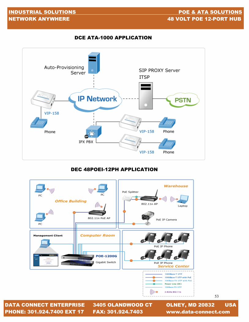
53
53
DATA CONNECT ENTERPRISE 3405 OLANDWOOD CT OLNEY, MD 20832 USA PHONE: 301.924.7400 EXT 17 FAX: 301.924.7403 www.data-connect.com
INDUSTRIAL SOLUTIONS POE & ATA SOLUTIONS NETWORK ANYWHERE 48 VOLT POE 12-PORT HUB
DCE ATA-1000 APPLICATION
DEC 48POEI-12PH APPLICATION

54
54
DATA CONNECT ENTERPRISE 3405 OLANDWOOD CT OLNEY, MD 20832 USA PHONE: 301.924.7400 EXT 17 FAX: 301.924.7403 www.data-connect.com
INDUSTRIAL SOLUTIONS POE & ATA SOLUTIONS NETWORK ANYWHERE 48 VOLT POE 12-PORT HUB
The Data Connect DCE 48V POEI-12PH is 12-Port IEEE 802.3af Power over Ethernet Web Management injector Hub and complies with the IEEE 802.3, IEEE 802.3u and IEEE 802.3af standards. With 12 10/100Base-TX Fast Ethernet ports, DCE 48V POEI-12PH support full 48V DC power for any remote IEEE 802.3af powered device (PD) like Wireless LAN Access Point, IP phone and IP Camera. Supporting PoE power budget of 190 watts, DCE 48V POEI-12PH provides sufficient 15.4 watts PoE power to 12 remote PD devices. The DCE 48V POEI-12PH is installed between a regular Ethernet Switch and the powered devices, injecting power without affecting the data transmission. They offer a cost effective and quick solution to upgrade network system to IEEE 802.3af Power over Ethernet system without replacing the existing Ethernet switch. There are 24 RJ-45 STP ports on the front panel of PoE Injector Hub, in which the 12 ports on the lower stack function as “Data Input” and the other 12 ports on the upper stack function as “PoE (Data and Power) output”. Each of the “PoE output” port on the upper stack operates as a power injector which transmits DC Voltage to the CAT5 cable so as to transfer data and power simultaneously between the Injector and Splitter. To efficiently manage the powered devices, DCE 48V POEI-12PH provide Web management interface in which administrators can use the functions including port Enable/Disable, port priority, system con-figuration, and Username/Password changing and with smart features for powered device. The PoE injector hub can auto-detect the power status of each port and show massages on its Web management inter-face. These features also provide a cost-effective way to manage the device via from Internet whenever you are at work or home.
SPECIFICATIONS
INTERFACE: “Data” Input Ports: 12 x RJ-45 STP “PoE (Data + Power)” Output Ports: 12 x RJ-45 STP MANAGEMENT PORT: 1 x RJ-45; 0/100Base-TX, auto negotiation, auto-MDI / MDIX LED: System: Power x 1 (Green) MANAGEMENT PORT 2X: 10/100 (Green/Orange) Per PoE Port: PoE in Use x 1 (Green) NETWORK CABLE: 10Base-T: 2-Pair UTP Cat 3, 4, 5, up to 100m (328ft) 100Base-TX: 2-Pair UTP Cat, 3, 4, 5, up to 100m (328ft) EIA/TIA-568 100-ohm STP (100m) DIMENSION (W x D x H): 440 x 200 x 44 mm (1U height) WEIGHT: 7.2kg POWER REQUIREMENT: 100-240V AC, 50/60 Hz POWER CONSUMPTION: 200 watts max OPERATING TEMPERATURE: 0 - 50ºC STORAGE TEMPERATURE: -40 - 70ºC HUMIDITY: 5 - 95% (Non-condensing) COOLING: Fan x 1 POE STANDARD: IEEE 802.3af Power over Ethernet / Mid-Span PSE POE POWER SUPPLY TYPE: Mid-Span POE POWER OUTPUT: Per Port DC 48V 15.4 Watts POWER PIN ASSIGNMENT: 4/5(+) 7/8(-) POE POWER BUDGET: 190 Watts POE MANAGEMENT: Power Limit by Priority and Total Limit Per port power enable/disable Power feeding priority Current usage and status Total power consumption MANAGEMENT FEATURE: System/Management functions setup Web firmware upgrade SNMP Trap for alarm notification of events STANDARDS COMPLIANE: IEEE 802.3 10Base-T Ethernet IEEE 802.3 100Base-TX Fast Ethernet
IEEE 802.3af Power over Ethernet REGULATION COMPLIANCE: FCC Part 15 Class A, CE
KEY FEATURES INTERFACE: 24-Port RJ-45 STP 12-Port “Data input” 12-Port “PoE (Data + Power) output” 1 10/100Base-TX Management port with Auto MDI / MDI-X feature POE: Complies with IEEE 802.3af Power over Ethernet Mid-Span PSE Up to 12 IEEE 802.3af devices powered Support PoE Power up t 15.4 watts for each PoE ports Auto detect powered device (PD) Circuit protection prevent power interference between ports Remote power feeding up to 100m POE MANAGEMENT: Total PoE power budget control Pert port PoE function enable/disable PoE Port Power feeding priority Per PoE port power limit PD classification detection MANAGEMENT: Web interface for remote management Firmware upgrade through Web interface Smart Discovery utility automatically finds DCE devices n the net-work SNMP Trap for alarm notification of events HARDWARE: 19-inch rack mountable; 1U height Reset button for reset to default setting and system reboot LED indicators for PoE ready and PoE activity STANDARD COMPLIANCE: IEEE 802.3 10Base-T IEEE 802.3u 100Base-TX IEEE 802.af Power over Ethernet FCC Part 15 Class A, CE
<———————————-PREVIOUS PAGE APPLICATION
ORDERING INFORMATION DCE/48V-POEI-12PH 48V POE INJECTOR 12 PORT
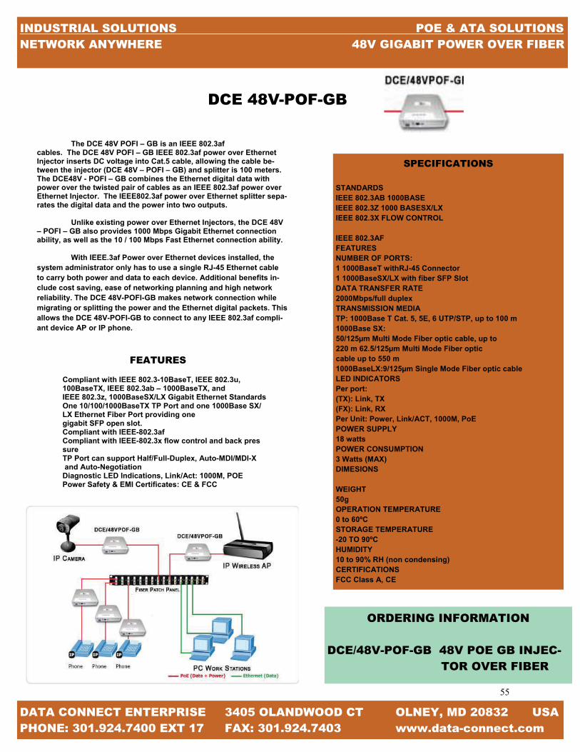
55
55
DATA CONNECT ENTERPRISE 3405 OLANDWOOD CT OLNEY, MD 20832 USA PHONE: 301.924.7400 EXT 17 FAX: 301.924.7403 www.data-connect.com
INDUSTRIAL SOLUTIONS POE & ATA SOLUTIONS NETWORK ANYWHERE 48V GIGABIT POWER OVER FIBER
The DCE 48V POFI – GB is an IEEE 802.3af cables. The DCE 48V POFI – GB IEEE 802.3af power over Ethernet Injector inserts DC voltage into Cat.5 cable, allowing the cable be-tween the injector (DCE 48V – POFI – GB) and splitter is 100 meters. The DCE48V - POFI – GB combines the Ethernet digital data with power over the twisted pair of cables as an IEEE 802.3af power over Ethernet Injector. The IEEE802.3af power over Ethernet splitter sepa-rates the digital data and the power into two outputs.
Unlike existing power over Ethernet Injectors, the DCE 48V
– POFI – GB also provides 1000 Mbps Gigabit Ethernet connection ability, as well as the 10 / 100 Mbps Fast Ethernet connection ability.
With IEEE.3af Power over Ethernet devices installed, the system administrator only has to use a single RJ-45 Ethernet cable to carry both power and data to each device. Additional benefits in-clude cost saving, ease of networking planning and high network reliability. The DCE 48V-POFI-GB makes network connection while migrating or splitting the power and the Ethernet digital packets. This allows the DCE 48V-POFI-GB to connect to any IEEE 802.3af compli-ant device AP or IP phone.
FEATURES Compliant with IEEE 802.3-10BaseT, IEEE 802.3u, 100BaseTX, IEEE 802.3ab – 1000BaseTX, and IEEE 802.3z, 1000BaseSX/LX Gigabit Ethernet Standards One 10/100/1000BaseTX TP Port and one 1000Base SX/ LX Ethernet Fiber Port providing one gigabit SFP open slot. Compliant with IEEE-802.3af Compliant with IEEE-802.3x flow control and back pres sure TP Port can support Half/Full-Duplex, Auto-MDI/MDI-X and Auto-Negotiation Diagnostic LED Indications, Link/Act: 1000M, POE Power Safety & EMI Certificates: CE & FCC
SPECIFICATIONS
STANDARDS IEEE 802.3AB 1000BASEIEEE 802.3Z 1000 BASESX/LX IEEE 802.3X FLOW CONTROL IEEE 802.3AF FEATURES NUMBER OF PORTS: 1 1000BaseT withRJ-45 Connector 1 1000BaseSX/LX with fiber SFP Slot DATA TRANSFER RATE 2000Mbps/full duplex TRANSMISSION MEDIA TP: 1000Base T Cat. 5, 5E, 6 UTP/STP, up to 100 m 1000Base SX: 50/125µm Multi Mode Fiber optic cable, up to 220 m 62.5/125µm Multi Mode Fiber optic cable up to 550 m 1000BaseLX:9/125µm Single Mode Fiber optic cable LED INDICATORS Per port: (TX): Link, TX (FX): Link, RX Per Unit: Power, Link/ACT, 1000M, PoE POWER SUPPLY 18 watts POWER CONSUMPTION 3 Watts (MAX) DIMESIONS WEIGHT 50g OPERATION TEMPERATURE 0 to 60ºC STORAGE TEMPERATURE -20 TO 90ºCHUMIDITY 10 to 90% RH (non condensing) CERTIFICATIONSFCC Class A, CE
ORDERING INFORMATION DCE/48V-POF-GB 48V POE GB INJEC- TOR OVER FIBER
DCE 48V-POF-GB

56
56
DATA CONNECT ENTERPRISE 3405 OLANDWOOD CT OLNEY, MD 20832 USA PHONE: 301.924.7400 EXT 17 FAX: 301.924.7403 www.data-connect.com
INDUSTRIAL SOLUTIONS POE & ATA SOLUTIONS NETWORK ANYWHERE 60 VOLT POE SURGE SUPPRESSOR
The Data Connect Surge Protected Registered Jacks protect devices against a wide range of transient surges from any source including lightening induced transient surges and the frequent daily sags in electric-ity that are followed by transient surges induced when the electricity is restored to the original level. Most dangerous surges are incidental in nature and can be attributed to: turning on the florescent lights, micro-wave, toaster oven, space heaters, computers, and ma-chinery; and use of printers, copiers, and or faxes. Of course the more obvious is manufacturing and welding shops on your electrical grid, restoration of power, and lightening. Unfortunately, transient surges can enter communi-cation equipment and inflict damage through any con-nection, not just the AC power lines. Facilities with reliable AC power protectors can still experience surge-related downtime. The transient AC surges are clamped to the shared common ground that can result in damage to expensive communication hardware; as these surges pass through other grounded connec-tions and into sensitive electronic equipment, particu-larly network communication equipment. The DCE SPRJ series of Surge Protected Registered Jacks cover a broad range of infrastructure require-ments. From single-line dial-up devices to Category 6 Ethernet devices, the DCE SPRJ series of surge protec-tors can insure that your infrastructure is protected.
FEATURES -Compact form factor -Extremely fast 5 nanoseconds response time -High Energy handling capability -Ability to protect almost all devices that transmits data over copper
ORDERING INFORMATION DCE/60V-POE 60 VOLT POE SURGE SUPPRESSOR
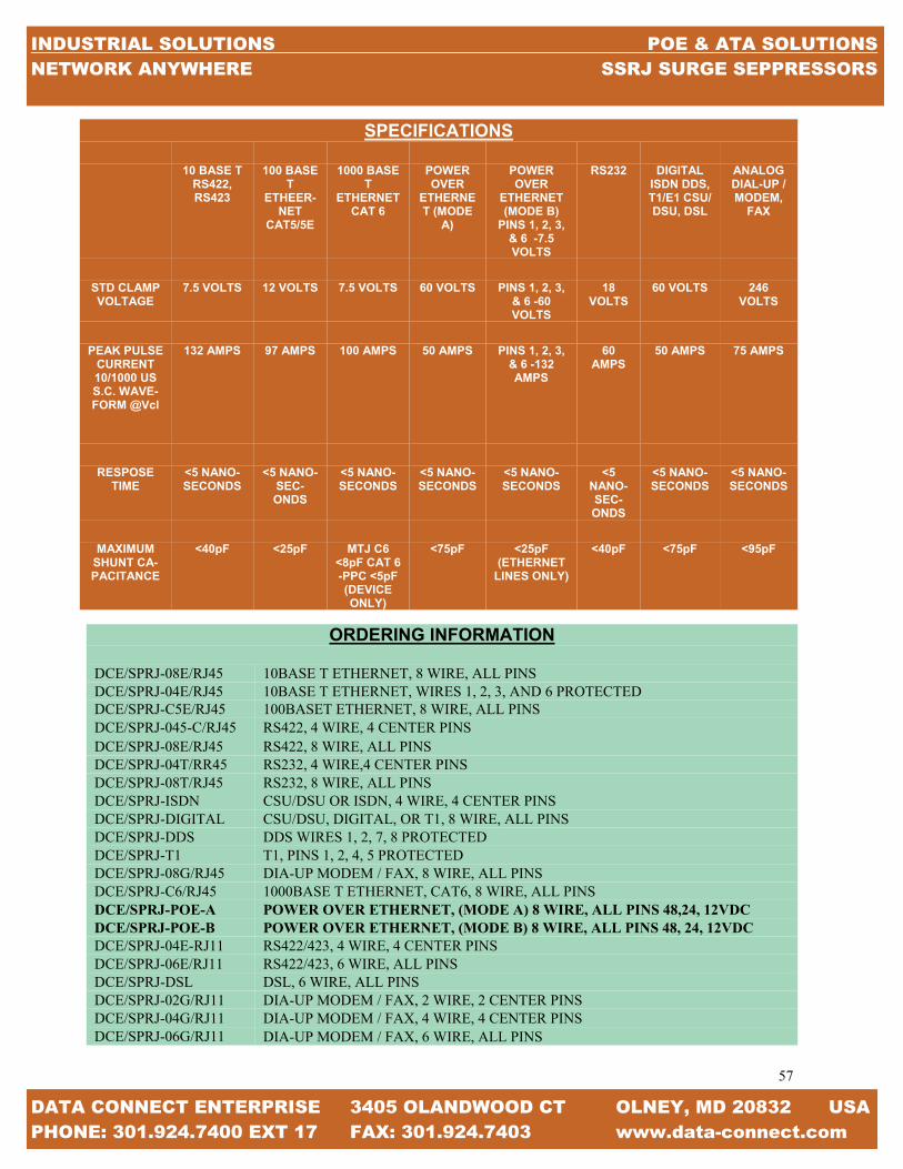
57
57
INDUSTRIAL SOLUTIONS POE & ATA SOLUTIONS NETWORK ANYWHERE SSRJ SURGE SEPPRESSORS
DATA CONNECT ENTERPRISE 3405 OLANDWOOD CT OLNEY, MD 20832 USA PHONE: 301.924.7400 EXT 17 FAX: 301.924.7403 www.data-connect.com
SPECIFICATIONS
10 BASE T
RS422, RS423
100 BASE T
ETHEER-NET
CAT5/5E
1000 BASE T
ETHERNET CAT 6
POWER OVER
ETHERNET (MODE
A)
POWER OVER
ETHERNET (MODE B)
PINS 1, 2, 3, & 6 -7.5 VOLTS
RS232 DIGITAL ISDN DDS, T1/E1 CSU/DSU, DSL
ANALOG DIAL-UP / MODEM,
FAX
STD CLAMP VOLTAGE
7.5 VOLTS 12 VOLTS 7.5 VOLTS 60 VOLTS PINS 1, 2, 3, & 6 -60 VOLTS
18 VOLTS
60 VOLTS 246 VOLTS
PEAK PULSE CURRENT 10/1000 US S.C. WAVE-FORM @Vcl
132 AMPS 97 AMPS 100 AMPS 50 AMPS PINS 1, 2, 3, & 6 -132 AMPS
60 AMPS
50 AMPS 75 AMPS
RESPOSE TIME
<5 NANO-SECONDS
<5 NANO-SEC-ONDS
<5 NANO-SECONDS
<5 NANO-SECONDS
<5 NANO-SECONDS
<5 NANO-SEC-ONDS
<5 NANO-SECONDS
<5 NANO-SECONDS
MAXIMUM SHUNT CA-PACITANCE
<40pF <25pF MTJ C6 <8pF CAT 6-PPC <5pF (DEVICE ONLY)
<75pF <25pF (ETHERNET
LINES ONLY)
<40pF <75pF <95pF
ORDERING INFORMATION DCE/SPRJ-08E/RJ45 10BASE T ETHERNET, 8 WIRE, ALL PINS DCE/SPRJ-04E/RJ45 10BASE T ETHERNET, WIRES 1, 2, 3, AND 6 PROTECTED DCE/SPRJ-C5E/RJ45 100BASET ETHERNET, 8 WIRE, ALL PINS DCE/SPRJ-045-C/RJ45 RS422, 4 WIRE, 4 CENTER PINS DCE/SPRJ-08E/RJ45 RS422, 8 WIRE, ALL PINS DCE/SPRJ-04T/RR45 RS232, 4 WIRE,4 CENTER PINS DCE/SPRJ-08T/RJ45 RS232, 8 WIRE, ALL PINS DCE/SPRJ-ISDN CSU/DSU OR ISDN, 4 WIRE, 4 CENTER PINS DCE/SPRJ-DIGITAL CSU/DSU, DIGITAL, OR T1, 8 WIRE, ALL PINS DCE/SPRJ-DDS DDS WIRES 1, 2, 7, 8 PROTECTED DCE/SPRJ-T1 T1, PINS 1, 2, 4, 5 PROTECTED DCE/SPRJ-08G/RJ45 DIA-UP MODEM / FAX, 8 WIRE, ALL PINS DCE/SPRJ-C6/RJ45 1000BASE T ETHERNET, CAT6, 8 WIRE, ALL PINS DCE/SPRJ-POE-A POWER OVER ETHERNET, (MODE A) 8 WIRE, ALL PINS 48,24, 12VDC DCE/SPRJ-POE-B POWER OVER ETHERNET, (MODE B) 8 WIRE, ALL PINS 48, 24, 12VDC DCE/SPRJ-04E-RJ11 RS422/423, 4 WIRE, 4 CENTER PINS DCE/SPRJ-06E/RJ11 RS422/423, 6 WIRE, ALL PINS DCE/SPRJ-DSL DSL, 6 WIRE, ALL PINS DCE/SPRJ-02G/RJ11 DIA-UP MODEM / FAX, 2 WIRE, 2 CENTER PINS DCE/SPRJ-04G/RJ11 DIA-UP MODEM / FAX, 4 WIRE, 4 CENTER PINS DCE/SPRJ-06G/RJ11 DIA-UP MODEM / FAX, 6 WIRE, ALL PINS

58
58
MODEL VOLT-AGE
MAX SPEED
T1 E1 T3 E3 STA-TION
STAND-ALONE
RACK-MOUNT
FIBER-TEL 100-
240VAC 64 KBPS √ √ √
FIBER-TEL/FAX 100-
240VAC 14,4KBPS √ √ √
FIBER-TEL/DIAL 100-
240VAC 14.4KBPS √ √ √
COPPER-T 100-
240VAC 1.544 MBPS √ √
COPPER-E 100-
240VAC 2.048 MBPS √ √
FIBER-T 100-
240VAC 1.544 MBPS √ √ √
FIBER-E 100-
240VAC 2.048 MBPS √ √ √
QUADFIBER-T 100-
240VAC 6.176 MBPS √ √ √
QUADFIBER-E 100-
240VAC 8.192 MBPS √ √ √
FIBER-T3 100-
240VAC 45 MBPS √ √
FIBER-E3 100-
240VAC 34 MBPS √ √
RM20UI 100-
240VAC CHASSIS √ √
RM16UI 100-
240VAC CHASSIS √ √ √
RM1UI 100-
240VAC CHASSIS √ √
DIAL LINE & DEMARC EXTENSION CHART
DATA CONNECT ENTERPRISE 3405 OLANDWOOD CT OLNEY, MD 20832 USA PHONE: 301.924.7400 EXT 17 FAX: 301.924.7403 www.data-connect.com
INDUSTRIAL SOLUTIONS DIAL LINE & DEMARC EXTENSION NETWORK ANYWHERE FIBER CHASSIS

59
59
INDUSTRIAL SOLUTIONS DIAL LINE & DEMARC EXTENSION NETWORK ANYWHERE DIAL LINE & DEMARC EXTENSION CHART
DATA CONNECT ENTERPRISE 3405 OLANDWOOD CT OLNEY, MD 20832 USA PHONE: 301.924.7400 EXT 17 FAX: 301.924.7403 www.data-connect.com
DIAL LINE & DEMARC EXTENSION SOLUTIONS
In This Section Fiber Telephone Line Extension Pg 60 Fiber Fax Line Extension Pg 60 Fiber Dial Modem Line Extension Pg 60 Copper T1 DEMARC Extension Pg 61 Copper E1 DEMARC Extension Pg 61 Fiber T1 DEMARC Extension Pg 62 Fiber E1 DEMARC Extension Pg 62 Quad Fiber T1 Extension Pg 63 Quad Fiber E1 Extension Pg 63 Fiber T3 Extension Pg 64 Fiber E3 Extension Pg 64 20 Slot Universal Power 19” Chassis Pg 65 16 Slot Universal Power 19”Chassis Pg 66 1 slot Universal Power 19” Chassis Pg 67
The Technology In recent years it has become apparent that fiber-optics are steadily replacing copper wire as an appropriate means of communication signal transmission. They extend the long distances between local phone systems as well as provid-ing the backbone for many network systems. Other system users include cable television services, university cam-puses, office buildings, industrial plants, and electric utility companies. A fiber-optic system is similar to the copper wire system that fiber-optics is replacing. The difference is that fiber-optics use light pulses to transmit information down fiber lines instead of using electronic pulses to transmit informa-tion down copper lines. Looking at the components in a fiber-optic chain will give a better understanding of how the system works in conjunction with wire based systems. At one end of the system is a transmitter. This is the place of origin for information coming on to fiber-optic lines. The transmitter accepts coded electronic pulse information coming from copper wire. It then processes and translates that information into equivalently coded light pulses. A light-emitting diode (LED) or an injection-laser diode (ILD) can be used for generating the light pulses. Using a lens, the light pulses are funneled into the fiber-optic medium where they travel down the cable. The light (near infrared) is most often 1,300nm on Multi-mode fiber and 1300nm for single-mode fiber and 1,500nm is used for longer extensions. In fiber optic communications, wavelength-division multiplexing (WDM) is a technology which multiplexes a number of optical carrier signals onto a single optical fiber using different wavelengths (colors) of laser lights. This technique enables bidirectional communications over one strand of fiber, as well as multiplication of capacity. At Data Connect, we offer a wide range of products to suite your network needs. We can assist you in finding a solu-tion that maximizes your investment while providing the solutions that will benefit your customers both now and for years to come. With the ability to use copper or fiber at your customer’s locations, Dial Line & DEMARC extension be-comes a wise choice and made easy.

60
60
DATA CONNECT ENTERPRISE 3405 OLANDWOOD CT OLNEY, MD 20832 USA PHONE: 301.924.7400 EXT 17 FAX: 301.924.7403 www.data-connect.com
INDUSTRIAL SOLUTIONS DIAL LINE & DEMARC EXTENSION NETWORK ANYWHERE IN THIS SECTION & THE TECHNOLOGY
DCE FIBER TEL / FAX / DIAL
DCE/Fiber-Tel is a fiber dial line and telephone con-verter extender that is used to connect PSTN voice, fax and modem signals to distant Plain Old Telephone (POTS) devices such as analog phones, faxes, and dial modems. DCE/Fiber-Tel is required to implement an end to end system. FXS mode is the reciprocal unit and has ability to act as PSTN and connects to a telephone device. When the DCE/Fiber-Tel card is placed in the DCE/RM16 rack with SNMP management, in-band management allows viewing the card and re-mote converters status, type, version, fiber link status, on hook status and alarms. Both card and remote can be configured to enable or disable the port, reset the port and set the FXO (CO) and FXS (CPE) mode.
FEATURES Extend voice, fax and modem transmission from 2km
to120km over fiber Network management via terminal, web or SNMP in DCE/RM20 chassis Supports telephone voice transmission Support caller ID pass through Selectable FXO or FXS mode Supports FXS to FXS hot line
APPLICATIONS
SPECIFICATIONS
Connector: 1x (SC, ST, FC) or SFP LC Cable Type: MM 62.2/125µm, 50/125µm. SM 9/125µm Cable Length: MM 2km, SM 15/30/50/80/120km WDM 20/40/60/80km Wavelength: MM1310nm, SM 1310 1550nmRx WDM 1310Tx/1550Rx (type A), 1550Tx/1310Rx (type B) Connector: RJ-11 Impedance: 600 ohms Coding: 16bits liner loop Current: 10~100mA Ring Frequency: Acceptable 20~50Hz Insertion Loss: 0.0 ± 1.0db at 1000Hz Impedance: 600 ohms Coding: 16bits liner Dial: DTMF and Dial Paul Battery source: 48VDC ±4V Ringing Waveform: Sine Wave Ringing Frequency: 20/25/30/50 Hz selectable FXS to FXs: On/1 sec, off /2 sec FXO to FXS: Reproduces the cadence detected by FXO Insertion Loss: 0.0±1.0dB at 1000Hz REN: 4.0B (Ring Equivalence Number) LEDs: Power, FX Link, Phone Act, Test Power: DC in 12V Power Consumption: <5W Dimensions: 155 x 88 x 23 (D x W x H) mm Weight: 120g Temperature: 0~50˚C (operation), 0~70˚C (storage) Humidity : 10~90% non condensing Certification: CE, FCC, LVD, and RoHS
ORDERING INFORMATION DCE/FIBER-TEL Fiber Telephone Line Extension DCE/FIBER-TEL/FAX Fiber Fax Line Extension DCE/FIBER-TEL/DIAL Fiber Dial Modem Extension

61
61
INDUSTRIAL SOLUTIONS DIAL LINE & DEMARC EXTENSION NETWORK ANYWHERE FOR YOUR NOTES
DATA CONNECT ENTERPRISE 3405 OLANDWOOD CT OLNEY, MD 20832 USA PHONE: 301.924.7400 EXT 17 FAX: 301.924.7403 www.data-connect.com
The Data Connect Copper-T and Copper-E are 4-wire repeaters for use on customer owned lines or to extend telephone company demarcs. The Extenders are used to extend in-house T1 and E1 lines in campus and high rise environments. Each pair of T1 and E1 Extenders may be located up to 5000 feet apart. The Extenders circuitry is rated to -36 dB dynamic range the T1 rate of 1.544 Mbps and -43 dB dynamic range at an E1 rate of 2.048 Mbps. As implemented, the parts are slightly de-rated to provide long life at extended temperature range. Therefore the distances specified in this document are only 5000 feet solid cop-per 22 AWG, two twisted pair is the preferred cable for connection between the Extenders. Connection to the Extenders is made through RJ-45 modular connectors or 4-wire screw down barrier stripes. Each Extender come standard with two screws down bar-rier strips and one RJ-45 connector. If only RJ-45 connections are desired extra RJ-45 adaptors (part number 9502122) can be or-dered. The DCE Copper-T and Copper-E are powered by a small wall-mount transformer. The Extenders are designed for connections between T1 equipment such as PBXs, T1/E1 multiplexers, T1/E1 line drivers, CSUs, routers or any other T1/E1 equipment requiring long customer owned cable runs. The T-Extenders/ E-Extenders are transparent to the type of data sent over the T1/E1 The T-Extenders are most often used in pairs to extend a tele-phone company demarc. For example, if a CSU or DSU is limited at 655 feet and is connecting to a phone company smart jack demarc which is limited to 655 feet, the T-Extenders are used in pairs to extend that distance up to 5000 feet.
FEATURES Extend Phone Company Demarc T1 or E1 4-wire repeater Extends T1 or E1 lines Up to 5000 feet between units RJ-45 or screw down connectors Simple connection to 4-wire circuits Inexpensive solution to long cable runs 120/220 VAC, 12, 24, 48, or 125 VDC available 1U high rack mountable, 1, 2, or 3x19” rack 20 slot rack chassis option
SPECIFICATIONS GENERAL T1 repeater or E1 repeater Extends T1 or E1 bi-polar signals Up to 5000 feet between T-extenders Up to 4000 feet between E-extenders INDICATORS Power ACCESSORIES RJ-45 wiring adaptor p/n 9502122 Customer to demarc RJ-45 cable p/n 9500095 Customer to customer RJ-45 crossover cable p/n 9500099 Rack shelf, 1 U for 1 to 3 T1/E1 EXTENDERS 20 slot, 4U high 19” rack mount chassis PHYSICAL / ELECTRICAL 5.5” x &.5 x 1.5” 100 ohm T1, 120 ohm E1 interface 2 Ibs including wall transformer 120 VAC external wall transformer supply Optional 220 VAC, 12, 24, 48, 125 VDC 30 ma Operating Temperature: -40˚C to +70˚C Operating Humidity: <98% non- considering WIRE Two twisted pair solid copper other types will affect operational distance CONNECTORS RJ-45 modular 8-conductor connectors Pin 1 = Receive Pin 2 =Receive Pin 4 =Transmit Pin 5 =Transmit 4-Wire barrier strip Pin 1 = Receive Pin 2 =Receive
Connect the transmit pair of one extender to the receive pair of the other extender. Pairs are not polarity sensitive. Units supplied with 2 screw downs, 1 RJ-45.
Note! This product is NOT for 10BaseT or Ethernet
ODERING INFORMATION DCE/COPPER-T T-1 Copper Extender DCE.COPPER-E E1 Copper Extender
DCE COPPER-T

62
62
DATA CONNECT ENTERPRISE 3405 OLANDWOOD CT OLNEY, MD 20832 USA PHONE: 301.924.7400 EXT 17 FAX: 301.924.7403 www.data-connect.com
INDUSTRIAL SOLUTIONS DIAL LINE & DEMARC EXTENSION NETWORK ANYWHERE FIBER T / E EXTENSION
The DCE/Fiber-E is a media E1 extender for G.703 transmission. The BNC model provides unbalanced 75 Ohm coaxial connections while the RJ-45 model provides balanced 120 Ohm connections over twisted pair wiring. The DCE/Fiber-T is a fiber media T1 extender for G.703 T1 transmission and features an RJ-45 connector for connection to 100 Ohm twisted pair wiring. When the DCE/Fiber-T/E card is placed in the DCE/Fiber-T/E-SA-KIT with SNMP management the card status, type, version, fiber link status, E1 or T1 link status and alarms can all be displayed. Configuration is also available to enable or disable the port, reset the port, do far end fault setting, and initiate local or far end loop-back tests.
FEATURES: Network management via Terminal or SNMP in FRM301 Chassis T1/E1 RJ-45(USOC RJ-48C) or Coax (BNC) to Fiber Converter Support AMI or B8ZS/HDB3 line codes Unframed (transparent clear channel) User selectable line code setting Far End Fault (FEF) setting Loop back test
SPECIFICATIONS STANDARD E1: ITU-T G.703, G.704, G.706, G.732, G.823 T1: ITU-T G.703, G.704, AT&T TR-62411, ANSI T.403 LEDs PWR, Fiber Link, Line (e1 or T1) Link, Test Mode DCE/FIBER-T/E-LP External AC Adapter 9VDC@ 1A DCE/FIBER-T/E-UI AC Model: 100-240 VAC ± 10% Frequency 50-60 Hz DC Model: 24-72 VDC ± 10% ENVIRONMENT Temperature: 0-50°C (Operating) 0-70°C (Storage) HUMIDITY 20-80% non condensing (Operating) 10-90% (Storage) POWER CONSUMPTION DCE/Fiber-T/E-LP: < 5W DCE/Fiber-T/E-UI: < 2W DIMENSIONS DCE/Fiber-T/E-LP: 85.6mm x 122.6mm x 20mm DCE/Fiber-T/E-UI: 85.6mm x 191.7mm x 30mm WEIGHT DCE/Fiber-T/E-LP: 300g DCE/Fiber-T/E-UI: AC model: 500g DC model: 550g COMPLIANCE CE, FCC Class MTBF 65000 Hours
APPLICATIONS
PRODUCT POWER INTERFACE
TYPE CONNECTOR
TYPE CONNECTIVITY:
DISTANCE
___/_____-_ __ ___ __ ___
DCE/FIBER-T UI E1R ST 002: 2km
DCE/FIBER-E LP E1B SC 015: 15km
T1R LC 030: 30km
050: 50km
080: 80km
120: 120km
*20A: 20km
*20B: 20km
[WDM only]
*40A: 40km
*40B: 40km
[WDM only]
*20A must use couple with 20B *40A must use couple with 40B
ORDERING INFORMATION
DCE FIBER-T/E

63
63
DATA CONNECT ENTERPRISE 3405 OLANDWOOD CT OLNEY, MD 20832 USA PHONE: 301.924.7400 EXT 17 FAX: 301.924.7403 www.data-connect.com
INDUSTRIAL SOLUTIONS DIAL LINE & DEMARC EXTENSION NETWORK ANYWHERE QUAD FIBER T / E ENTENSION
The DCE/QuadFiber-T/E is a 1U half 19” stand-alone or rack mountable T1/E1 Extender featuring a point-to-point multiplexer for 4*E1 or 4*T1 (selectable) transmissions over a single fiber optic link. Its half-rack for-mat make it ideal for low cost multiplexing applications that require up to 4-channel. All channels provide completely transparent transmission of E1 or T1 regardless of frame mode, clock source or timeslot assignment. Available in either AC or DC models, the AC supplies operate from 100~240VAC while DC supplies operate from 18~72VDC. A Wide range of transceiver selection provides fiber connection with SC, FC or ST type connectors in multimode or single mode and at distance from 2 to 120km as well as BiDi (single fiber) at distances of 20, 40, 60, or 80km. Additional options include “Order Wire” phone connectors (FXS port) and a SNMP management.
FEATURES 1U stand-alone unit Channel service setting and remote loop-back setting via front panel DIP switch or serial console Far End Fault (FEF) on fiber link, selectable On-line Bit Error Rate monitor feature with four error-rate classes Dual color LEDs indicators Optional dedicated Order Wire phone port (FXS, RJ-11 port) Console port and one alarm relay Optional SNMP management, Telnet, and Web Based local and re-
SPECIFICATIONS Connector: 1x9 (SC, ST, FC) Data rate: 38Mbps Bit Error Rate: Less then 10¯¹¹ Cable Type: MM 62.2/125µm, 50/125µm. SM 9/125µm Distance: MM 2km, SM 15/30/50/80/120km, WDM 20/40/60/80km Wavelength: 1310, 1550nm Consol: RS232 (DB9F) Async SNMP: RJ45 Order wire: RJ11 E1: BNC 75 Ω, RJ45 Ω, T1 RJ45 100 Ω, 100 Meters Ω E1:ITU-T, T1:ITU-T, ATT&T, ANSI LEDs: PWR, Alarm, Far End /Near End Error, System Failure, E1/T1 status Power: 100~240VAC, DC24: 18 ~ 36V, DC48: 36 ~ 72V Power Consumption: < 20W Dimensions (D x W x H) mm: 235 x 195 x 45mm Weight: 850g Temperature: 0~50°C (Operating), 0~70°C (Storage) Humidity: 10~90% non-condensing Certification: CE, FCC, RoHS MTBF: 57350 hours
PRODUCT POWER INTERFACE
TYPE CONNECTOR
TYPE CONNECTIVITY:
DISTANCE
___/_________-_ __ ___ __ ___ DCE/QUADFIBER-T UI E1R ST 002: 2km
DCE/QUADFIBER-E DC E1B SC 015: 15km
T1R LC 030: 30km
050: 50km
080: 80km
120: 120km
*20A: 20km
*20B: 20km
[WDM only]
*40A: 40km
*40B: 40km
[WDM only]
*20A must use couple with 20B *40A must use couple with 40B
ORDERING INFORMATION
APPLICATIONS
DCE-QUADFIBER-T/E
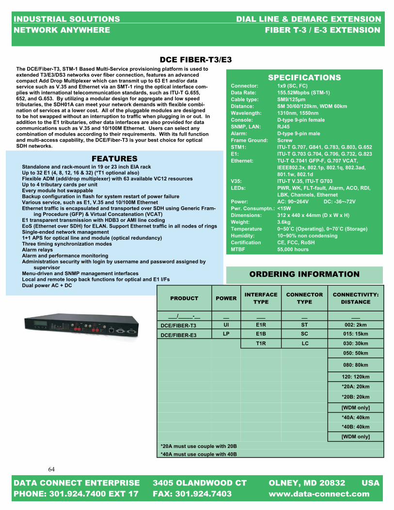
64
64
INDUSTRIAL SOLUTIONS DIAL LINE & DEMARC EXTENSION NETWORK ANYWHERE FIBER T-3 / E-3 EXTENSION
DATA CONNECT ENTERPRISE 3405 OLANDWOOD CT OLNEY, MD 20832 USA PHONE: 301.924.7400 EXT 17 FAX: 301.924.7403 www.data-connect.com
The DCE/Fiber-T3, STM-1 Based Multi-Service provisioning platform is used to extended T3/E3/DS3 networks over fiber connection, features an advanced compact Add Drop Multiplexer which can transmit up to 63 E1 and/or data service such as V.35 and Ethernet via an SMT-1 ring the optical interface com-plies with international telecommunication standards, such as ITU-T G.655, 652, and G.653. By utilizing a modular design for aggregate and low speed tributaries, the SDH01A can meet your network demands with flexible combi-nation of services at a lower cost. All of the pluggable modules are designed to be hot swapped without an interruption to traffic when plugging in or out. In addition to the E1 tributaries, other data interfaces are also provided for data communications such as V.35 and 10/100M Ethernet. Users can select any combination of modules according to their requirements. With its full function and multi-access capability, the DCE/Fiber-T3 is your best choice for optical SDH networks.
FEATURES Standalone and rack-mount in 19 or 23 inch EIA rack Up to 32 E1 (4, 8, 12, 16 & 32) (*T1 optional also) Flexible ADM (add/drop multiplexer) with 63 available VC12 resources Up to 4 tributary cards per unit Every module hot swappable Backup configuration in flash for system restart of power failure Various service, such as E1, V.35 and 10/100M Ethernet Ethernet traffic is encapsulated and transported over SDH using Generic Fram-
ing Procedure (GFP) & Virtual Concatenation (VCAT) E1 transparent transmission with HDB3 or AMI line coding EoS (Ethernet over SDH) for ELAN. Support Ethernet traffic in all nodes of rings Single-ended network management 1+1 APS for optical line and module (optical redundancy) Three timing synchronization modes Alarm relays Alarm and performance monitoring Administration security with login by username and password assigned by
supervisor Menu-driven and SNMP management interfaces Local and remote loop back functions for optical and E1 I/Fs Dual power AC + DC
SPECIFICATIONS Connector: 1x9 (SC, FC) Data Rate: 155.52Mbpbs (STM-1) Cable type: SM9/125µm Distance: SM 30/60/120km, WDM 60km Wavelength: 1310nm, 1550nm Console: D-type 9-pin female SNMP, LAN: RJ45 Alarm: D-type 9-pin male Frame Ground: Screw STM1: ITU-T G.707, G841, G.783, G.803, G.652 E1: ITU-T G.703 G.704, G.706, G.732, G.823 Ethernet: TU-T G.7041 GFP-F, G.707 VCAT, IEEE802.3x, 802.1p, 802.1q, 802.3ad, 801.1w, 802.1d V35: ITU-T V.35, ITU-T G703 LEDs: PWR, WK, FLT-fault, Alarm, ACO, RDI, LBK, Channels, Ethernet Power: AC: 90~264V DC: -36~-72V Pwr. Consumptn.: <15W Dimensions: 312 x 440 x 44mm (D x W x H) Weight: 3.6kg Temperature 0~50˚C (Operating), 0~70˚C (Storage) Humidity: 10~90% non condensing Certification CE, FCC, RoSH MTBF 55,000 hours
PRODUCT POWER INTERFACE
TYPE CONNECTOR
TYPE CONNECTIVITY:
DISTANCE
___/_____-__ __ ___ __ ___
DCE/FIBER-T3 UI E1R ST 002: 2km
DCE/FIBER-E3 LP E1B SC 015: 15km
T1R LC 030: 30km
050: 50km
080: 80km
120: 120km
*20A: 20km
*20B: 20km
[WDM only]
*40A: 40km
*40B: 40km
[WDM only]
*20A must use couple with 20B *40A must use couple with 40B
ORDERING INFORMATION
DCE FIBER-T3/E3

65
65
INDUSTRIAL SOLUTIONS DIAL LINE & DEMARC EXTENSION NETWORK ANYWHERE FIBER CHASSIS
DATA CONNECT ENTERPRISE 3405 OLANDWOOD CT OLNEY, MD 20832 USA PHONE: 301.924.7400 EXT 17 FAX: 301.924.7403 www.data-connect.com
DCE/FIBER CHASSIS The DCE/RM_UI Chassis Product line includes various metal chas-sis sizes, which can hold from one to twenty DCE/FIBER slide-in modules. The DCE/RM1U is one slot chassis, which can be installed with one single width blade card for stand-alone applications. The available power options are external AC adapter, built-in AC, DC power or built-in AC+DC, AC+AC, DC+DC dual power. The DCE//RM1U-M is one slot chassis with DB9 console port for local man-agement, which can be installed with one single width blade card for stand-alone applications. The available power options are built-in AC, DC or built-in AC+DC dual power. The DCE/RM2U is a two slot chassis, which can be installed with one double width blade card for stand-alone applications. The only available Power supply option is an external AC adapter.
SPECIFICATIONS One slot chassis with single width blade line cards. Available in six types: external power adapter or power built-in AC, DC, AC+DC, AC+AC, or DC+DC No fans Dimensions: External adapter: 160 x 88 x 24mm (D x W x H) Internal power: 180 x 135 x 35mm (D x W x H) External adapter: Input voltage 100 ~ 240VAC 50/60Hz Output voltage 12VDC 1A AC power 100 ~ 240VAC DC power 24VDC, 48VDC, 72VDC
The DCE RM16UI is a 3U, 19(23)" fiber media platform rack that features 16 cards capacity. Supported cards include Ethernet copper to fiber converters for 10/100Base-TX or 10/100/1000Base-TX over multimode fiber (up to 2 km), single mode fiber (up to 120
FEATURES 3U 19” 16-slot Chassis with AC/DC power redundancy All modules and cards support hot-swapping Two alarm relays SNMP: Supports local / remote monitor Supports local configuration Supports online TFTP f/w upgrade Supports multiple accesses for SNMP management Supports Windows® GUI management, Telnet, Serial console Supports console RS-232 port and 10/100Base-T Ethernet port Supports SNMP standard MIB II and proprietary MIB
SPECIFICATIONS Temperature: 0 - 50°C (Operating), 0 - 70o C (Storage) Humidity: 20-80% non-condensing (Operating), 10-90% (Storage) Power: Input: 1+1 Redundancy mode, Hot-swappable AC Power Module Input: Universal, 100~240VAC; Freq.: 47~63 Hz AC Power Consumption: 150W DC Power Module: Input: 36~72 VDC & 18~-36VDC (option) DC Power Consumption: 150W Fan: Removable type for ease maintenance Dimensions: 440mm x 280mm x 130.6mm (L x W x H). Weight: 6.2Kg (include 1 AC power modules & two ear panels for rack-mounting) Compliance: FCC part 15, Subpart B, Class A, ANSI C63.4:2003, CE EN55022:2006, Class A, EN55024:1998+A1:2001+A2:2003 LVD: EN 60 950-1:2001 MTBF: 65,000 h (25°C)
The DCE RM16UI is the complete solution to aggregate standalone fiber extenders into a single chassis, 19" or 23" rack mountable. The chassis can hold DCE FIBER-T/E and FIBER-TEL. FRM301 is the per-fect choice to better organize the increasing number of standalone media converter into a single shelf, while keeping a total control and management through the SNMP module. The chassis provides redun-dant power supply system with "hot swap" feature, to provide con-tinuous smooth operation of the units installed. It can hold both AC (110V) and DC (48V) power supply units, either in mixed or same type of power input. The FRM220-CH20 is a 2U high 19" Rack, 20 slot modular media con-verter rack. It provides an economic solution in high density fiber con-verter installations in enterprises or central offices. All critical compo-nents, power, fans, management module and interface cards are hot swappable, allowing online field replacement. The hot-swappable power modules can be chosen from AC 100-240V, DC 18-36 or DC 36-72V. The chassis also has a pair of alarm relays and is able to stack
FEATURES 2U 19” 20-slot Chassis with AC/DC power redundancy Chassis cascade up to 10 with one IP management Chassis backplane consists of passive components All modules and cards support hot-swap function Two alarm relays NETWORK MANAGEMENTCONTROLLER: Supports local / remote monitor and configuration Supports local / remote online TFTP f/w upgrade Fiber transceiver status & info display Supports multiple accesses for SNMP management Supports Web GUI management, Telnet, Serial console Supports console RS-232 port and 10/100Base-T Ethernet port Supports SNMP standard MIB II and proprietary MIB Supports NTP time synchronization Supports 100 entries system log
SPECIFICATIONS NEXT PAGE ———————>
_____________________________________________________
____________________________________________________

66
66
DATA CONNECT ENTERPRISE 3405 OLANDWOOD CT OLNEY, MD 20832 USA PHONE: 301.924.7400 EXT 17 FAX: 301.924.7403 www.data-connect.com
INDUSTRIAL SOLUTIONS DIAL LINE & DEMARC EXTENSION NETWORK ANYWHERE FIBER T-3 / E-3 EXTENSION
FIBER CHASSIS ORDERING INFORMATION DCE/RM1UI DATA CONNECT ONE SLOT CHASSIS 100-240VAC DCE/RM1UI-PS DATA CONNECT ONE SLOT REDUNDANT POWER SUPPLY 100-240VAC DCE/RM1UI-PSVDC48 DATA CONNECT ONE SLOT REDUNDANT POWER SUPPLY 48VDC DCE/RM1UI-PSVDC24 DATA CONNECT ONE SLOT REDUNDANT POWER SUPPLY 24VDC DCE/RM1UI-PSVDC72 DATA CONNECT ONE SLOT REDUNDANT POWER SUPPLY 72VDC DCE/RM16UI DATA CONNECT SIXTEEN SLOT CHASSIS 100-240VAC DCE/RM16UI-PSVAC DATA CONNECT SIXTTEN SLOT REDUNDANT POWER SUPPLY 100-240VAC DCE/RM16UI-PSVDC48 DATA CONNECT SIXTEEN SLOT REDUNDANT POWER SUPPLY 36 -72VDC DCE/RM16UI-PSVDC24 DATA CONNECT SIXTEEN SLOT REDUNDANT POWER SUPPLY 18-36VDC DCE/RM16UI-FAN DATA CONNECT SIXTEEN SLOT FAN DCE/RM20UI DATA CONNECT TWENTY SLOT CHASSIS 100-240VAC DCE/RM20UI-PSVAC DATA CONNECT TWENTY SLOT REDUNDANT POWER SUPPLY 100-240VAC DCE/RM20UI-PSVDC48 DATA CONNECT TWENTY SLOT REDUNDANT POWER SUPPLY 36 -72VDC DCE/RM20UI-PSVDC24 DATA CONNECT TWENTY SLOT REDUNDANT POWER SUPPLY 18-36VDC DCE/RM20UI-FAN DATA CONNECT TWENTY SLOT FAN
SPECIFICATIONS
One slot chassis for FRM220 Single width blade line cards. Available in six types: external power adapter or power built-in AC, DC, AC+DC, AC+AC, or DC+DC No fans Dimensions: External adapter: 160 x 88 x 24mm (D x W x H) Internal power: 180 x 135 x 35mm (D x W x H) External adapter: Input voltage 100 ~ 240VAC 50/60Hz Output voltage 12VDC 1A AC power 100 ~ 240VAC DC power 24VDC, 48VDC, 72VDC
DCE FIBER CHASSIS (Cont’d)

67
67
INDUSTRIAL SOLUTIONS DIAL LINE & DEMARC EXTENSION NETWORK ANYWHERE FIBER T-3 / E-3 EXTENSION
DATA CONNECT ENTERPRISE 3405 OLANDWOOD CT OLNEY, MD 20832 USA PHONE: 301.924.7400 EXT 17 FAX: 301.924.7403 www.data-connect.com
NOTES

68
68
INDUSTRIAL SOLUTIONS CHANNEL BANKS SOLUTIONS NETWORK ANYWHERE THE TECHNOLOGY
DATA CONNECT ENTERPRISE 3405 OLANDWOOD CT OLNEY, MD 20832 USA PHONE: 301.924.7400 EXT 17 FAX: 301.924.7403 www.data-connect.com
The Technology
A channel bank is a multiplexer. A device that puts many slow speed voice or data conversations onto one high speed link; and, controls the flow of those conversations. Typically the device that sits between a digital T1 circuit; and, a couple of dozen voice grade lines coming out of a PBX. One side of the channel bank will be connections for terminating two pairs of wires or coaxial cable that brings in the T1 carrier. On the other side of the channel bank are connections for terminating multiple tip and ring single line analog phone lines or several digital data streams. Sometimes you need channel banks and sometimes you don’t. For example if your shipping a bundle of voice conversations from one local digital PBX to another digital PBX across town you don’t need a channel bank but CSU (Commercial Service Unit) on each side to connect and recognize the T1 formatted signal. If one or both of the PBX is analog, you will need a channel bank to recognize the T1 formatted signal. A channel bank converts a group of FXS or FXO interfaces to higher speed interfaces. When you need to connect multiple analog/ legacy devices like phones and faxes like those found in a MTU/MDU (Multi Tenant Unit/ Multi Dwell-ing Unit) facility, to a VoIP network. A generic Multiport FXS/FXO gateway is just not good enough. You need a high port density channel bank solution which not only aggregates your legacy analog lines but also allows you configur-able IP Routing and Quality of Service based on your specific requirements. At Data Connect, we offer a wide range of products to suite your network needs. We can assist you in finding a solution that maximizes your investment while providing the solutions that will benefit your customers both now and for years to come. With the ability to use a channel bank at your customer’s locations to extend a bundle of simulta-neous phone calls becomes a wise choice and made easy.

69
69
INDUSTRIAL SOLUTIONS CHANNEL BANKS SOLUTIONS NETWORK ANYWHERE D4 CHANNEL BANK CHART
DATA CONNECT ENTERPRISE 3405 OLANDWOOD CT OLNEY, MD 20832 USA PHONE: 301.924.7400 EXT 17 FAX: 301.924.7403 www.data-connect.com
D4 CHANNEL BANK CHART
MODEL FXS FXO CHASSIS VOICE IP CSU
DCE/D4-FXS-FULL 24 0 √ √ 0 √
DCE/D4-FXO-FULL 0 24 √ √ 0 √
DCE/D4-MOD 0 0 √ 24 √
DCE-D4-MOD-4FXS 4 0 √ 0
DCE/D4-MOD-4FXO 0 4 √ 0
DCE/D4-0FXS-4FXO 0 4 √ √ 20 √
DCE/D4-0FXS-8FXO 0 8 √ √ 16 √
DCE/D4-0FXS-12FXO 0 12 √ √ 12 √
DCE/D4-0FXS-16FXO 0 16 √ √ 8 √
DCE/D4-0FXS-20FXO 0 20 √ √ 4 √
DCE/D4-4FXS-0FXO 4 0 √ √ 20 √
DCE/D4-4FXS-4FXO 4 4 √ √ 16 √
DCE/D4-4FXS-8FXO 4 8 √ √ 12 √
DCE/D4-4FXS-12FXO 4 12 √ √ 8 √
DCE/D4-4FXS-16FXO 4 16 √ √ 4 √
DCE/D4-4FXS-20FXO 4 20 √ √ 0 √
DCE/D4-8FXS-0FXO 8 0 √ √ 16 √
DCE/D4-8FXS-4FXO 8 4 √ √ 12 √
DCE/D4-8FXS-8FXO 8 8 √ √ 8 √
DCE/D4-8FXS-12FXO 8 12 √ √ 4 √
DCE/D4-8FXS-16FXO 8 16 √ √ 0 √
DCE/D4-12FXS-0FXO 12 0 √ √ 12 √
DCE/D4-12FXS-4FXO 12 4 √ √ 8 √
DCE/D4-12FXS-8FXO 12 8 √ √ 4 √
DCE/D4-12FXS-12FXO 12 12 √ √ 0 √
DCE/D4-16FXS-0FXO 16 0 √ √ 8 √
DCE/D4-16FXS-4FXO 16 4 √ √ 4 √
DCE/D4-16FXS-8FXO 16 8 √ √ 0 √
DCE/D4-20FXS-0FXO 20 0 √ √ 4 √
DCE/D4-20FXS-4FXO 20 4 √ √ 0 √

70
70
Your telecommunication needs are made easier to manage with Data Connect Enterprise’s T1 Channel Bank products. Data Connect satisfies the needs of any T1 channel bank application, no matter how stringent the requirement. Unique Data Connect features like real-time T1 status on our four-line by 40 character (4x40) LCD display, or automatic, hands-off con-figuration utilizing artificial intelligence software, and crystal clear audio quality proves that Data Connect T1 products are in a top class of their own. Knowing the T1 Channel Bank is ready to perform means that you can spend more time developing important customer relationships. Data Connect Enterprise offers you a complete line of low cost T1 chan-nel banks including, FXS, FXO, or mixed mode FXS/FXO analog interfaces. As a bonus, every system comes with our standard fractional V.35 data port. Add the Data Connect Modular; internal power supply system to list and Data connect crushes the competition. Using Asterisk? Data Connect T1 Channel Bank allows you to utilize analog phones and writing in conjunction with leading-edge Asterisk tech-nology, without having to buy expensive IP telephones. Why go IP when you can save on installations by using existing wiring? With the Data Con-nect T1 Channel Bank, you can use lower cost analog phones with digital feature and get guaranteed T1 voice quality; all while enjoying Asterisk VoIP technology for off-premise connectivity. Data Connect T1 Channel Banks are rugged. In the rare case of trouble, our technical staff is ready to give you support you need, when you need it.
FEATURES Low cost Fully populated FXS Fully populated FXO Modular FXS/FXO mixed mode capability CSU self-configuration to proper mode Digital Signal Processor (DSP) monitoring real-time Field Software upgradable Distinctive ring in loop start mode Caller ID enable in loop start mode FLASH base system configuration
SPECIFICATIONS Asterisk soft PBX tested and ready. 4x40 LCD real-time status display shows inde-pendent AB bit signaling Automatic T1 configuration using artificial intel-ligence soft (no configuration switches) CSU auto detects T1 modes: D4 or ESF, AMI, B8ZS T1 CSU via RJ48C, with line V.35 fractional data interface, user selectable to 56K or 64K Self diagnostic, verbose error reporting, loop-back modes Single channel configuration (Each channel may have a different analog start mode, signal-ing protocol, line current, or gain.) Telco network uptime and downtime for T1 his-tory Remote connection via RS-232C or Ethernet (optional) via windows based graphical user interface Immediate, Wink, Loop, Ground, RevPol (loop), and three DID start protocols FSK: Digital DSP · Echo cancellation · Ring Cadence Control Line Current Limit—18mA to 45mA · TX and RX gain control of -5db to +6db Power Down Control 1 to3 seconds. FXO: Digital DSP · Dynamic Impedance Matching Ring Cadence Monitoring Timer · TX and RX gain control of -15db to +12db Power: 110VAC, 220VAC, and -48VDC modu-lar power a supply models Size: 3.5” H x 17”W x 8.5”D Weight: 12Ib maximum 19”, 23” or wall mounting kit standard T1 and analog cables included
ORDERING INFORMATION DCE/D4-FXS-FULL DATA CONNECT D4 CHANNEL BANK 24 FXS / 0 FXO DCE/D4-FXO-FULL DATA CONNECT D4 CHANNEL BANK 0 FXS / 24 FXO DCE/D4-MOD DATA CONNECT D4 CHANNEL BANK CHSSIS ONLY DCE-D4-MOD-AN-4FXS DATA CONNECT D4 CHANNEL BANK 4 FXS NO CHASSIS DCE/D4-MOD-AN-4FXO DATA CONNECT D4 CHANNEL BANK 4 FXO NO CHASSIS DCE/D4-0FXS-4FXO DATA CONNECT D4 CHANNEL BANK 0 FXS / 4 FXO DCE/D4-0FXS-8FXO DATA CONNECT D4 CHANNEL BANK 0 FXS / 8 FXO DCE/D4-0FXS-12FXO DATA CONNECT D4 CHANNEL BANK 0 FXS / 12 FXO DCE/D4-0FXS-16FXO DATA CONNECT D4 CHANNEL BANK 0 FXS / 16 FXO DCE/D4-0FXS-20FXO DATA CONNECT D4 CHANNEL BANK 0 FXS / 20 FXO DCE/D4-4FXS-0FXO DATA CONNECT D4 CHANNEL BANK 4 FXS / 0 FXO DCE/D4-4FXS-4FXO DATA CONNECT D4 CHANNEL BANK 4 FXS / 4 FXO DCE/D4-4FXS-8FXO DATA CONNECT D4 CHANNEL BANK 4 FXS / 8 FXO DCE/D4-4FXS-12FXO DATA CONNECT D4 CHANNEL BANK 4 FXS / 12 FXO DCE/D4-4FXS-16FXO DATA CONNECT D4 CHANNEL BANK 4 FXS / 16 FXO DCE/D4-4FXS-20FXO DATA CONNECT D4 CHANNEL BANK 4 FXS / 20 FXO DCE/D4-8FXS-0FXO DATA CONNECT D4 CHANNEL BANK 8 FXS / 0 FXO DCE/D4-8FXS-4FXO DATA CONNECT D4 CHANNEL BANK 8 FXS / 4 FXO DCE/D4-8FXS-8FXO DATA CONNECT D4 CHANNEL BANK 8 FXS / 8 FXO DCE/D4-8FXS-12FXO DATA CONNECT D4 CHANNEL BANK 8 FXS / 12 FXO DCE/D4-8FXS-16FXO DATA CONNECT D4 CHANNEL BANK 8 FXS / 16 FXO DCE/D4-12FXS-0FXO DATA CONNECT D4 CHANNEL BANK 12 FXS / 0 FXO DCE/D4-12FXS-4FXO DATA CONNECT D4 CHANNEL BANK 12 FXS / 4 FXO DCE/D4-12FXS-8FXO DATA CONNECT D4 CHANNEL BANK 12 FXS / 8 FXO DCE/D4-12FXS-12FXO DATA CONNECT D4 CHANNEL BANK 12 FXS / 12 FXO DCE/D4-16FXS-0FXO DATA CONNECT D4 CHANNEL BANK 16 FXS / 0 FXO DCE/D4-16FXS-4FXO DATA CONNECT D4 CHANNEL BANK 16 FXS / 4 FXO DCE/D4-16FXS-8FXO DATA CONNECT D4 CHANNEL BANK 16 FXS / 8 FXO DCE/D4-20FXS-0FXO DATA CONNECT D4 CHANNEL BANK 20 FXS / 0 FXO DCE/D4-20FXS-4FXO DATA CONNECT D4 CHANNEL BANK 20 FXS / 4 FXO
INDUSTRIAL SOLUTIONS CHANNEL BANKS SOLUTIONS NETWORK ANYWHERE D4 CHANNEL BANK
DATA CONNECT ENTERPRISE 3405 OLANDWOOD CT OLNEY, MD 20832 USA PHONE: 301.924.7400 EXT 17 FAX: 301.924.7403 www.data-connect.com

71
71
INDUSTRIAL SOLUTIONS CHANNEL BANKS SOLUTIONS NETWORK ANYWHERE COMPETITIVE ANALYSIS
DATA CONNECT ENTERPRISE 3405 OLANDWOOD CT OLNEY, MD 20832 USA PHONE: 301.924.7400 EXT 17 FAX: 301.924.7403 www.data-connect.com
Manufacturer: Adtran Carrier Access Carrier Access DCE/D4-FXS-FULL Model: Total Access 750 Adit 600 Access Bank I 24FXS
Web Site Address: adtran.com carrieraccess.com carrieraccess.com channelbanks.com
Physical size: 2 U 2 U 1 U 2 U
Weight: 8 lbs. 11.8 lbs. 14.5 lbs. 12 lbs.
Mounting: 19" or 23" rack mount 19", 23" or wall 19", 23" or wall 19", 23", desktop or wall
Channel Capacity: 24 FXS 24 FXS 24 FXS 24 FXS
T1 Requirements: Standard 4 wire T1 Standard 4 wire T1 Standard 4 wire T1 Standard 4 wire T1
Start Protocols: Immediate, Loop, Immediate, Loop, Loop or Ground Immediate, Loop,
Ground, and WINK Ground, and WINK Ground, and WINK
Ground, WINK and 3 different DID
Framing Protocals: D4, ESF or TR08 D4 or ESF D4, ESF, TR08 or SLC-96 D4 or ESF
Line Coding: AMI or B8ZS AMI or B8ZS AMI or B8ZS AMI or B8ZS
Analog Output: FXO or FXS FXO or FXS 24 Loop start lines 24 Loop start lines
Display of signaling bits? No No No Yes
Data Output: Dual V.35 cards V.34 and V.90 V.35, RS530,
RS530A or RS449
Method of configuration: PC, serial port or modem PC, serial port or modem Dip switches
Automatic Plug and Play T1 configuration
Caller ID capable: Yes Yes
Power Requirements: 130VAC max. 115VAC (-)48 VDC 110VAC
Power Usage: 3.5A 1A input 1A
Operating Environment: (-)40C to 70C 32F-104F/0C-40C 32F-122F/0C-50C 32F-166F/0C-70C
Humidity: Non-cond. up to 95% Non-cond. up to 95% Non-cond. up to 95% Non-cond. up to 95%
Manufacturers Warranty: 10 year limited warranty 10 year limited warranty 5 year warranty 5 year limited warranty
List Price: $2,256 $4,375 $2,375 $1,495
COMPETITIVE ANALYSIS
Every DCE channel bank will configure itself to the T1 when plugged in and powered up. Also standard with each DCE Channel bank is a 4 line by 40-character LCD display. This display in conjunction with the four menu buttons can be used to manually configure your channel bank if your installation calls for a more specific needs. I Every system comes with a fractional V.35 data port (for free) that can be used for the IP router connection. If you have unused DS0 time slots you can use that band width for IP connectivity.
The DCE channel banks feature a single CSU (for free) that is software controlled, software programmed and will self boot to the proper mode right out of the box.
Now, with our new modular channel bank, you can custom build a DCE channel bank to your exact specifications. Don’t need a full 24 line channel bank? No problem. Build your channel bank in four channel increments. Need to combine FXS and FXO lines into one channel bank? Again, not a problem. You can mix and match FXS and FXO cards also in four line increments into one DCE chassis.

72
72
INDUSTRIAL SOLUTIONS INDUSTRIAL MODEMS NETWORK ANYWHERE MODEM SELECTION GUIDE
DATA CONNECT ENTERPRISE 3405 OLANDWOOD CT OLNEY, MD 20832 USA PHONE: 301.924.7400 EXT 17 FAX: 301.924.7403 www.data-connect.com
MO
DE
M S
ELE
CT
ION
GU
IDE
IT
U-T
ST
AN
DA
RD
B
EL
L
ST
AN
DA
LO
NE
PC
B C
AR
D
KE
Y F
EA
TU
RE
S
MO
UN
T
MO
DE
L #
V92
56K
V90
56K
V34B
IS
33.6K
V34
28.8K
V29
HF
P
19.2K
9.6K
V32B
IS
14.4K
V27
4.8K
V22
2.4K
V23
1.2K
202T
1.2K
103 .3K
100-240 V
AC
LV
L
OW
VD
C
HV
H
IGH
VD
C R
AC
K-
MO
UN
T
OEM
DIA
L /
LE
AS
ED
2/4-W
IRE
V.42 /
V.42
BIS
SE
CU
-R
ITY
D
IN
RA
IL W
AL
L
IG56
√ √
√ √
√
√
√
√ √
D
2 √
√ √
√
IG56S
√
√ √
√
√
√
√
D
2
√
IM56
√
√
D
2
IML
56
√
√
L
2
MM
56
√
√ D
2
IG336
√ √
√
√
√
√ √
D
2 √
√ √
√
3600LP
√
√
√
√
√
√
D
/L
2,4 √
√
3342LP
√
√
√
√
√
√
D
/L
2,4 √
√
3342E/R
√
√
√
√
√
√
D
/L
2,4 √
√
3600UI
√ √
√
√
√ √
√
√
D/L
2,4
√
MIU
28.8
√
√
√
√ √
√ √
√ D
2
√
IG192H
FP
√
√
√ √
√ √
√ √
L
2,4
√ √
IG96H
FP
√
√
√ √
√ √
√ √
L
2,4
√ √
DS
P9612
√
√
√
√ √
√ √
√
L
2,4
MIU
9.6FP
D
√
√
√
√ √
√ √
L
2,4
IG144
√
√
√
√ √
D
2 √
√ √
√
1442E/R
√
√
√ √
√
D
,L
2,4 √
MIU
14.4
√
√
√ √
√ √
√ D
,L
2 √
2400E/R
√
√
√
D
2
√
MIU
2.4
√
√ √
√ √
√ D
2
√
IGV
.23
√
√ √
√ √
L
2,4
√ √
IG3202
T-
√ √
√ √
√ √
√
L
2,4
IG202
T
√
√ √
√ √
√
L
2,4
√
√
202TE
/R
√
√ √
√ √
√
L
2,4
MIU
202T
√
√ √
√ √
√ √
L
2,4
*MU
LT
I-PR
OT
OC
OL
ITU
-T V
.21, V.23, R
.35, R.37
, R.38
A, R
.38B, &
V.29, B
EL
L 20
2T &
103 CE
GE
LE
C 1200/6
00 BA
UD
& IN
DA
CT
IC 33 C
OM
MU
NIC
AT
ION
ST
AN
DA
RD
S

73
73
INDUSTRIAL SOLUTIONS INDUSTRIAL MODEMS NETWORK ANYWHERE IN THIS SECTION & THE TECHNOLOGY
DATA CONNECT ENTERPRISE 3405 OLANDWOOD CT OLNEY, MD 20832 USA PHONE: 301.924.7400 EXT 17 FAX: 301.924.7403 www.data-connect.com
IN THIS SECTION
ITU-T & BELL MODULATIONS / PROTOCOLS SPEED PAGE____
V.92 / V.90 56Kbps Pg 74-79 V34BIS 33.6Kbps Pg 80-85 V.34 28.8Kbps Pg 86 V.29 / V.27 / BELL 202T 19.2, 9.6, 4.8, & 1.2Kbps Pg 87-90 V.32BIS 14.4Kbps Pg 91-93 V.22 2.4Kbps Pg 94-95 V.23 1.2Kbps Pg 96 BELL 202T / 103 1.2Kbps Pg 97-101
The Technology
The word modem is an acronym for MOdulator / DEModulator. Modems are used to send digital data signals over analog circuits. The modem uses the Public Switched Telephone Network (PSTN) and either PSTN for dial or private copper wires for leased line or private wire applications. A 2-Wire Facility is one that supports transmis-sion in two directions simultaneously while mixing signals (Half Duplex) for 2-Wire Leased applications. A 4-Wire Facility is one that supports transmission in two directions but isolates the signals (Full Duplex) by Frequency, Time, and Space division plus other techniques that enable reflections to occur without causing the signals to mix together for 4-Wire Leased applications. Modems are governed by the International Telecommunications Union – Telecommunications (ITU-T) Service Sector based in Geneva, Switzerland. The ITU-T sets the (V. Series) standards including V.92 / V.90 at 56Kbps, V.34BIS at 33.6Kbps, V.34 at 28.8Kbps, V.29 / V.27 at 19.2, 9.6 & 4.8Kbps, V.32BIS at 14.4Kbps, V.22 at 2.4Kbps, and V.23 at 1.2Kbps. There are also BELL standards still used such as BELL202T at 1.2Kbps and BELL103 at .3Kbps. Most modems today come with built in error correction, data compression technology based on ITU-T Industry Standards and are used in a wide range of applications. ISDN Terminal Adapter, DDS Unit, T1/FT1 DSU/CSU, T1 CSU, DSL Router, and Cable Router are all called mo-dems but technically don’t modulate or demodulate. The modems in this section all modulate and demodulate and meet with the ITU-T and BELL standards. The Security features found in some of the modems offer Password Protection, Call Guard, and Call Back Security Options.. At Data Connect, we offer a wide range of modem products to suite your network needs. We can assist you in finding a solution that maximizes your investment while providing the solutions that will benefit your customers both now and for years to come. With the ability to match all requirements and standards, your choice becomes a wise choice and made easy by Data Connect expertise.

74
74
INDUSTRIAL SOLUTIONS INDUSTRIAL MODEMS NETWORK ANYWHERE V.92 / V.90 MODEM CHECK LIST
DATA CONNECT ENTERPRISE 3405 OLANDWOOD CT OLNEY, MD 20832 USA PHONE: 301.924.7400 EXT 17 FAX: 301.924.7403 www.data-connect.com
V.92 / V.90 MODEM CHECK LIST
MODEL MAX. SPEED HIGH VOLT.
LOW VOLT. DIAL LEASED
RACK MOUNT
DIN MOUNT
SECUR-ITY
WALL MOUNT PHOTO PAGE
DCE/IG56 56KBPS X X X X X 75
DCE/IG56S 56KBPS x x X x x X 76
DCE/1M56 56KBPS X X X X 77
DCE/IML56 56KBPS X X 78
DCE/MM56 56KBPS X X 79

75
75
INDUSTRIAL SOLUTIONS INDUSTRIAL MODEMS NETWORK ANYWHERE IG56
DATA CONNECT ENTERPRISE 3405 OLANDWOOD CT OLNEY, MD 20832 USA PHONE: 301.924.7400 EXT 17 FAX: 301.924.7403 www.data-connect.com
The Data Connect DCE/IG56 high-speed V.92 dial-line modems are de-signed and manufactured for rugged industrial applications over the Public designed Telephone Network (PSTN). The DCE/IG56 utilizes the industries latest V.92 modem technology to deliver outstanding fea-tures, performance and reliability in one cost-effective solution. The DCE/IG56 modems are ideally suited for industrial communica-tion applications including SCADA systems, RTs, traffic monitor and control, and industrial automation network. The DCE/IG56 supports TRUs equipped with an EIA RS-232 or RS-485 serial port. Data commu-nications speeds up to 56 kbps are supported. The modems incorporate the latest data-compression and error cor-rection standards for improved data transmission and reception over marginal and poor-quality telephone lines. The DCE/IG56 modems are powered by a wide range of AC and DC power supply voltages. Its low power consumption and low stand-by current technology design makes the DCE/IG56 ideal for battery-powered system as well as regular AC powered operation.
FEATURES
Worldwide operation Support: ITU-T - V.92 / V.34BIS / V.34 / V.32bis / V.32 / V.22bis / V.22 / V.23 / V.23 / V.21 V29 Fast POS / V.22bis fast connect Data Compression: V.44 / V.42bis/MNP 2 Error Correction: V.42/MNP 2/MNP 2 DTE/ Host Interface: EIA RS-232 and RS-485 Embedded AT Command set
63 embedded and upgradeable country profiles for worldwide homologation
NVRAM for configuration and country profile storage Built-in remote diagnostic and configuration management Heavy-duty surge protection provided at power supply and phone line inter-face Support wide range of AC and DC power supply options Supports DC power supplied from DTE or DB-9 connector Wide range of operating temperatures Optional mounting kits for DIN Rail mounting or wall mount
SPECIFICATIONS
Data modem : ITU-T - V.92: Up to 56kbps / V.34bis: Up to 33600bps / V.32bis: Up to 14400bps / V.32: Up to 9600bps / V.22bis: Up to 2400 bps / V.21: 0-300bps / Bell 212A: 1200bps / Bell 103: 0-300bps Fax Modem: Send and receive fax up 14.4 kbps V17, V29, V27ter, and V21 channel 2 EIA / TIA 578 Class 1, T.31 Class 1.0, and Class Data Format: Asynchronous, 7, 8 or 9 data bits, parity, 10- or 11- bit character with 1 0r 2 stop bits Modulation: Fully compatible with ITU-T V.92 / V.34 / V.32bis / V22bis / V.21 Bell 212A and Bell 103 compatible modes. Transmission Line Interface: 2-wire full duplex over PSTN / Connec-tor: RJ-11C DTE/RTU Interface: the modem provides serial ports to support RS-232 or RS-485 (selectable) interface RS-232 Interface: Connector : DB9-F Signals: RTS, CTS, CD, TD, RD, DTR, DSR, and RI RS-485 Interface: Connector: RJ-11C Signals: 4-wire full duplex or 2-wire half duplex TX+,TX-,RX+, and RX- LED Indicators: DTR, TXD, RXD, DCD, DSR, and RI Three models support various power options: standalone - 90-264VAC / 100-400VDC / 10-48VDC Idle mode: 65 mA@12V, 0.78 watts Normal mode: 75 mA@12V, 0.9 watts, typical Enclosure dimensions: 4.1”(W) x5.0”(L) x 1.3”(H) 104mm(W) x 127mm(L) x 33mm(H) Weight: 0.5 pound, without AC power module Operating Temperature: -40 to +85°C Storage Temperature: -40 to +85°C Humidity: up to 95% non-condensing Dry Contact Detection (Optional): Two optical isolated dry contact detections are provided for external devices (consult factory for additional information)
ORDERING INFORMATION
DCE/IG56: Standalone with security and AC Power Module 90-264 VAC
DCE/IG56SDC: Standalone with security and DC power 10-48 VDC
DCE/IG56S-HV standalone with security and AC Power module 90-264 VAC or 100-400 VDC
DCE/IG202T-DIN DCE/IG202T-WM
DCE IG56

76
76
INDUSTRIAL SOLUTIONS INDUSTRIAL MODEMS NETWORK ANYWHERE IG56S
DATA CONNECT ENTERPRISE 3405 OLANDWOOD CT OLNEY, MD 20832 USA PHONE: 301.924.7400 EXT 17 FAX: 301.924.7403 www.data-connect.com
The Data Connect DCE/IG56S high-speed V.92 security dial-line modems are designed and manufactured or rugged industrial application over the Public Switched Telephone Network (PSTN) with security features such as pass-word log-in and security call-back. The DCEIG56S utilizes the industries latest V.92 modem technology to deliver outstanding features, performance, and reliability in one cost-effective solution. The DCE/IG56S modems are ideally suited for industrial communication application including SCADA systems, RTs, traffic monitoring and control, and industrial automation networks. The DCE/IG56S supports RTUs equipped with an EIA RS-232 or RS-485 serial port. Data communications speed up to 56 kbps are supported. The modems incorporate the latest data-compression and error-correction standards for improved data transmission and reception over marginal and poor-quality telephone lines. Multiple levels of security with password verifications and security call back keep your valuable data se-cure from intruders. The DCE/IG56S modems are powered by a wide range of AC and DC power supply voltages. Its low power consumption and low stand-by current technology design makes the DCE/IG56S ideal for a battery-powered system as well as regular AC powered operations.
FEATURES
Worldwide Operation Support: ITU-T: V.92 / V.34 / V.32bis / V.32 / V.22bis / V.22 / V.23 / V.22 / V.21 V29 Fast POS / V.22bis fast connect /V.44 / V.42bis / MNP 2 Security Options: Password log-in / Security call-back DTE/Host Interface: EIA RS-232 & RS-485 Embedded AT command set
63 embedded and upgradeable country profiles for worldwide homologation
NVRAM for configuration and country profile storage Built-in remote diag-nostics and configuration management Heavy-duty surge protection provided at power supply and phone line inter-face Supports wide range of AC & DC power supply options Support DC power supplied from DTE or DB-9 connector Wide range of operating temperatures Optional mounting kits for DIN Rail mounting or wall mount
SPECIFICATIONS
ITU-T V.92: Up to 56kbps / V.34bis: Up to 33600bps / V.34: Up to 28800bps / V.32bis: Up to 14400bps / V.32: Up to 9600bps / V.22bis: Up to 2400bps V.21: 0-300bps / Bell 212A: 1200bps / Bell 103:0-300bps Send and receive fax up 14.4 kbps / V17 / V29 / V27ter / V21 chan-nel 2 / EIA/TIA 578 Class 1 / T.31 Class 1.0 / Data Format: Asynchronous, 7, 8 or 9 data bits, parity, 10- or 11- bit character with 1 0r 2 stop bits Modulation: Fully compatible with ITU-T V.92 / V.34 / V.32bis / V22bis / V.21 / Bell 212A / Bell 103. Transmission Line Interface: 2-wire full duplex over PSTN Connec-tor RJ-11C DTE/RTU Interface: the modem provides serial ports to support RS-232 or RS-485 (selectable) interface standards: RS-232 Interface: Connector : DB9-F Signals: RTS, CTS, CD, TD, RD, DTR, DSR, and RI RS-485 Interface: Connector: RJ-11C Signals: 4-wire full duplex or 2-wire half duplex TX+,TX-,RX+, and RX- Front panel LED Indicators - DTR, TXD, RXD, DCD, DSR, and RI Security Options: Password log-in / Security call-back Three models support various power options: standalone: 90-264VAC / 100-400VDC / 10-48VDC Consumption Idle mode: 65 mA@12V, 0.78 watts Consumption Normal mode: 75 mA@12V, 0.9 watts, Enclosure dimensions: 4.1”(W) x5.0”(L) x 1.3”(H) 104mm(W) x 127mm(L) x 33mm(H) Weight: 0.5 pound, without AC power module Operating Temperature: -40° to +85°C Storage Temperature: -40°to +85°C Humidity: up to 95% non-condensing Dry Contact Detection (Optional): Two optical isolated dry contact detections are provided for external devices (consult factory for additional information)
ORDERING INFORMATION
DCE/IG56S - Standalone with security and AC power module 90-264 VAC DCE/IG56SDC - Standalone with security and DC power 10-48 VDC DCE/IG56S-HV - Standalone with security and AC power module 90-264 VAC or 100-400 VDC DCE/IG202-DIN - DIN rail kit DCE/IG202-WMB – Wall mount bracket kit
DCE IG56S

77
77
INDUSTRIAL SOLUTIONS INDUSTRIAL MODEMS NETWORK ANYWHERE IM56
DATA CONNECT ENTERPRISE 3405 OLANDWOOD CT OLNEY, MD 20832 USA PHONE: 301.924.7400 EXT 17 FAX: 301.924.7403 www.data-connect.com
To service the growing need for efficient, reliable data communication in harsh environmental of utility substations and industrial facilities, has developed a 56bps modem that can operate from various AC/DC power supplies and survive high surge levels and extreme heat and cold. all this without compromising the performance expected from state-of-the-art communication devices With the rapid move toward “intelligent” substations, where meters, relay, RTU’s, SCADA systems, etc. are able to “talk” to a remote operator, communication devices such as modems are moving off the desktop and into the field, where the conveniences of 115VAC power outlets and cli-mate control are usually hard to find. The IM56 (low power industrial modem 56bps ) is an industrial grade modem incorporating data compression and error detection techniques for data throughput of up to 230kbps. The modem operates from -20˚C to +65˚C with over 95% relative humidity. Modem configuration is accom-plished through the “AT” command set.
FEATURES Modem Interface Units AC/DC powered substation hardened communica-tion interface units 5600kbps 2-wire dial-up line modem 12 to 400 AC/DC power supply IEC801-4 surge protection -20˚C to +65˚C operating temperature For meters relays, SCADA, etc.
ORDERING INFORMATION DCE/IM56 V.90 56k modem 100-240VAC DCE/IM56DC-12 V.90 56k modem 12VDC DCE/IM56DC-24 V.90 56k modem 24VDC DCE/IM56DC-48 V.90 56k modem 48VD DCE/IM56-HV V.90 56k modem 100-240VAC 85-400VDC
USER CONFIGURABLE HARDWARE OPTIONS AT command set ATS0=1 modem will answer on first ring AT&D0 modem will ignore DTR- factory default is AT which allows the modem to answer only if DTR is high AT&V to check the state of the “S” register use AT&V AT&W0 Don’t forget to burn the new codes into E-PROM by AT&W0 A good configuration for dumb mode operation is AT&F&C1&D0E0Q1S0=1&w0
SPECIFICATIONS
Modem Line Speeds: ITU-T V.90 - 56000bps ITU-T V.34 - 33600bps ITU-T V.32bis - 14400bps ITU-T V.32 - 9600bps ITU-T V.22bis - 2400bps ITU-T V.21 - 300bps Asynchronous Data: ITU-T V.42 error correction MNP 2-4, MNP 10EC ITU-T V.42bis data compression MNP5 Maximum Throughout: 230, 400bps Fax Send/Receive speeds: 14400bps Voice Capability DES Encryption Dial Back Minimum System Requirements RS232 Communication Port Communications Software Power Supply: 12-400VAC/DC Temperature: -25˚C to +65˚C Housing: Plastic case Dimensions: 3.5” x 6” x 1” Network Connections: PSTN via RJ11 Data Connections: RS232/V.24 via DB connector Data Interface: RS232 via DB9F connector
DCE IM56

78
78
INDUSTRIAL SOLUTIONS INDUSTRIAL MODEMS NETWORK ANYWHERE IML56
DATA CONNECT ENTERPRISE 3405 OLANDWOOD CT OLNEY, MD 20832 USA PHONE: 301.924.7400 EXT 17 FAX: 301.924.7403 www.data-connect.com
To service the growing need for efficient, reliable data communica-tion in harsh environments of utility substation and industrial facilities, has developed a 56kbps modem that can operate from various AC/DC power supplies and survive high surge levels and extreme heat and cold. All this without compromising the performance expected from state-of-the-art communication devices. With the rapid move toward “intelligent” substations, where meters, relays, RTU’s, SCADA sys-tems, etc. are able to “talk” to a remote operator, communications de-vices such as modems are moving off the desktop and into the field, where the conveniences of 115VAC power outlets and climate control are usually hard find. The IML56 (low power industrial modem 56kbps) is an industrial grade modem incorporated data compression and error detection tech-niques for data throughput of up to 230kbps. The modem operates from -20C to +65C with over 95% relative humidity.
For most applications, the modem configuration can be set using the DIP switch located on the right side of the unit without a PC. Typi-cally no familiarity with “AT” command is expected.
FEATURES
Modem Interface Units AC/DC powered Substation hardened communica-tion Interface units 5600kbps 2-Wire Leased Line modem 12 to 400 AC/DC power supply IEC801-4 surge protection -20C to +65C operation temperature
ORDERING INFORMATION
DCE/IML56 V.90 56K modem 100-240VAC DCE/IML56DC-12 V.90 56K modem 12VDC DCE/IML56DC-24 V.90 56K modem 24VDC DCE/IML56DC-48 V.90 56K modem 48VDC DCE/IML56-HV V.90 56K modem 100-240VAC 85-400VDC
SPECIFICATIONS
Modem Line Speeds: ITU-T V.90 - 56000bps ITU-T V.34 - 33600bps ITU-T V.32bis - 14400bps ITU-T V.32 - 9600bps ITU-T V.22bis - 2400bps ITU-T V.21 - 300bps Asynchronous Data: ITU-T V.42 error correction MNP 2-4, MNP 10EC ITU-T V.42bis data compression, MNP5 Maximum Throughput - 230,400bps Fax Send/ Receive Speeds - 14400bps (class 1&2) Voice Capable DES Encryption Dial Back Minimum System Requirements: RS232 Communications Ports Communications Software Power Supply: 12-400VAC/DC Temperature: -20C to +65C
Housing : Plastic casing Dimensions: 3.5” x 6” x 1” Network Connection: PSTN via RJ11 Data Connections: RS232/V.24 via DB9F connector Data Interface: RS232 via DB9F connector User Configurable Hardware Options: Via DIP switch settings: DTE Speed Auto Answer Local Echo Enable Result Code Enable Result Code Terse Flow Control Error Correction Host DTR Normal Deep Sleep
DCE IML56

79
79
INDUSTRIAL SOLUTIONS INDUSTRIAL MODEMS NETWORK ANYWHERE MM56
DATA CONNECT ENTERPRISE 3405 OLANDWOOD CT OLNEY, MD 20832 USA PHONE: 301.924.7400 EXT 17 FAX: 301.924.7403 www.data-connect.com
To service the growing need for efficient, reliable data communication in harsh environmental of utility substations and industrial facilities, has de-veloped a 56bps OEM modem that can operate from various AC/DC power supplies and survive high surge levels and extreme heat and cold. all this without compromising the performance expected from state-of-the-art com-munication devices With the rapid move toward “intelligent” substations, where meters, re-lay, RTU’s, SCADA systems, etc. are able to “talk” to a remote operator, communication devices such as OEM modems are moving off the desktop and into the field, where the conveniences of 115VAC power outlets and climate control are usually hard to find. The DCE MM56 (Internal OEM industrial modem 56bps ) is an industrial grade OEM modem incorporating data compression and error detection techniques for data throughput of up to 230kbps. The modem operates from -20˚C to +65˚C with over 95% relative humidity. Modem configuration is ac-complished through the “AT” command set.
FEATURES Modem Interface Units AC/DC powered substation hardened communica-tion interface units 5600kbps 2-wire dial-up line modem 12 to 400 AC/DC power supply IEC801-4 surge protection -20˚C to +65˚C operating temperature For meters relays, SCADA, etc.
ORDERING INFORMATION DCE/MM56 V.90 56k OEM modem
USER CONFIGURABLE HARDWARE OPTIONS AT command set ATS0=1 modem will answer on first ring AT&D0 modem will ignore DTR- factory default is AT which allows the modem to answer only if DTR is high AT&V to check the state of the “S” register use AT&V AT&W0 Don’t forget to burn the new codes into E-PROM by AT&W0 A good configuration for dumb mode operation is AT&F&C1&D0E0Q1S0=1&w0
SPECIFICATIONS Modem Line Speeds: ITU-T V.90 - 56000bps ITU-T V.34 - 33600bps ITU-T V.32bis - 14400bps ITU-T V.32 - 9600bps ITU-T V.22bis - 2400bps ITU-T V.21 - 300bps Asynchronous Data: ITU-T V.42 error correction MNP 2-4, MNP 10EC ITU-T V.42bis data compression MNP5 Maximum Throughout: 230, 400bps Fax Send/Receive speeds: 14400bps Voice Capability DES Encryption Dial Back Minimum System Requirements RS232 Communication Port Communications Software Power Supply: 12-400VAC/DC Temperature: -25˚C to +65˚C Housing: Plastic case Dimensions: 3.5” x 6” x 1” Network Connections: PSTN via RJ11 Data Connections: RS232/V.24 via DB connector Data Interface: RS232 via DB9F connector
DCE MM56

80
80
INDUSTRIAL SOLUTIONS INDUSTRIAL MODEMS NETWORK ANYWHERE V.34BIS MODEM CHECK LIST
DATA CONNECT ENTERPRISE 3405 OLANDWOOD CT OLNEY, MD 20832 USA PHONE: 301.924.7400 EXT 17 FAX: 301.924.7403 www.data-connect.com
MODEL MAX.
SPEED HIGH VOLT. LOW VOLT. DIAL LEASED RACK
MOUNT DIN MOUNT SECUR-ITY WALL
MOUNT PHOTO PAGE
DCE/V3600UI 33.6KBPS X X X X X 81
DCE/V3600LP+ 33.6KBPS X X X X X 82
DCE/IG336S 33.6KBPS X X X x 83
DCE/3342LP 33.6KBPS X X X X X 84
DCE/IG336 33.6KBPS X X X 85
DCE/3342E-004-2 33.6KBPS X X X X 86
DCE/3342R-004-2 33.6KBPS X X 87
DCE/3342E-208-4 33.6KBPS X X X X X 88
V.34BIS MODEM CHECK LIST

81
81
INDUSTRIAL SOLUTIONS INDUSTRIAL MODEMS NETWORK ANYWHERE V.3600UI
DATA CONNECT ENTERPRISE 3405 OLANDWOOD CT OLNEY, MD 20832 USA PHONE: 301.924.7400 EXT 17 FAX: 301.924.7403 www.data-connect.com
The Data Connect V.36UI series is a series of high performance, synchronous and asynchronous, full-duplex, multi-standard stand-alone or rack mounted modem. They are designed for use on 2-wire dial-up and 2/4-wire leased line circuits. The Data Connect V.3600UI series is fully compliant with ITU-T V.34 as well as being compatible with ITU-T recommended V.32bis/V.32, V.22bis, V.23 and V.21 international standards while operat-ing at 33600, 31200, 28800, 26400, 24000, 21600, 19200, 16800, 14400, 1200, 9600, 7200, 4800, 2400, 1200 and 300 bits per second. In V.34 mode the Data Connect V.3600UI series provides full duplex operation at up to 33.6Kbps on a 2/4-wire PSTN line, with features like line probing, symbol rate, and carrier frequency auto-matic selection. a range of performance enhancing techniques are available for V.34 mode, including adaptive pre-coding, adaptive re-emphasis, non-linear encoding (warping), constellation expan-sion, multi dimensional trellis coding, transmission power back-off (power drop), V.8 standard modem initialization, and shell map-ping. An in-band secondary channel allows the user to monitor and control the remote site unit. The Data Connect V.3600UI series also offers auto callback and leased-line security checks in addition to dial-up security checks. The Data Connect RM16MUI series can accommodate up to 16 modem cards with 16 ports, control unit and single or dual redun-dant power unit, it also dual redundant power supply which means if one power does fail the other one is capable of powering the entire rack.
FEATURES Fully compatible with ITU-T V.34+/V.34/V.32bis/V.32/V.26bis/V.22bis/V.22/V.23/V.21/V.24/V.28/V.25bis/V.54/V.52/V.42/V.42bis/V.14/V.13/V.8 and Bell 212A/103 19” rack accommodates up to 16 modem cards with hot-swap and profile copy functions Achiever throughput up to 115200bps V.13 simulated carrier in half-duplex MNP4®, V.42 error correction MNP5®, V.42bis data compression Extended AT and ITU-R V.25bis command set Leased lines dial back-up and restore in manual or auto mode Auto fallback and fall forward Remote configuration via secondary channel Front panel lock and password protect Password & callback security Diagnostic capabilities: Analog loopback and remote, digital loopback (with pattern or not); BERT test pattern using 511 Auto manual dialing/answer Front panel configuration via rubber switches and LCD Front panel key reset function G3FAX send/receive compatible with EIA-578 Class 1 FAX command (optional)
SPECIFICATIONS Compatibility: V.34+: 33.6/31.2 Kbps SM (4D TCM) V.34+: 28.8/ 26.4/24/21.6/19.2/16.8/14.4/12/9.6/7.2/ 4. 8/2.4 Kbps SM (4D TCM) V.32bis: 14400/12000/7200bps TCM V.32: 9600bps TCM, 9600/4800 bps QAM V.26bis: 2400/1200bps QAM, 1200bps BPSK V.22/Bell 212A: 1200bps DPSK V.23: 1200/75, 600/75bps FSK V.21/Bell 103:300 bps FSK Symbol Rate (Baud) and Carrier Frequency(Hz): 2400 Baud- 1600/ 1800 Hz 2800 Baud- 1680/ 1867 Hz 3000 Baud- 1800/2000 Hz 3200 Baud- 1829/ 1920 Hz 3429 Baud- 1959 Hz Data Format: Synchronous or Asynchronous Total bit length: 8, 9, 10, and 11 Data Speed: Asynchronous- 75/300/600/1200/2400/4800/7200/ 12000/14400/168/19200/21600/2400/26400/28800/ 31200/33600/38400/57600/76800/115200 bps Synchronous- 1200/2400/4800/7200/9600/12000/ 144400/16800/19200/21600/24000/26400/28800/ 31200/33600 bps DTE Interface: EIA RS-232C, ITU-T V.24/V.28 Line Requirement: Dial-up line, 2/4-wire leased line Transmit Level: Dial-up line: 0 to -15dBm; Leased line: 0 to -31dBm Receive Dynamic Range: -4 to -43/ 0 to -33dBm Equalization: Automatic adaptive EQ Call Progress Monitoring: Dial tone, Ring, Ring-back, Busy and backup dial Line Status Monitoring: TX level, RX level, S/N ratio, EQM value, delay, phase jitter, frequency offset, far-end echo, DTE format, retrain count, TX baud rate, RX baud rate, TX carrier, RX carrier, TX speed, RX speed, TX power back-off level, Interface lead monitoring . Memory: Non-volatile; 2user profiles and 10 phone numbers with 30 characters each Line Interface: RJ-11 for dial-up, JM8 (like RJ45) for leased line Transmit Clock: Internal, Loopback, or External Dialing Command and Type: Extended AT and V.25bis using Tone/Pulse/Mixed Flow Control: RTS/CTS, XON/XOFF, CTS only Enclosure dimensions: 7.1” W x 10.3”L x 1.9”H; 4.2 Ibs Rack Mount dimensions: 18.9” W x 14.9”L x 8.7”H Temperature: Operation: 0˚ to +50˚C, Storage: 0˚ to +50˚C Humidity: Up to 95% (non-condensing)
ORDERING INFORMATION DEC/V3600UI V3600UI STANDALONE 100-240VAC DCE/V3600UI-48 V3600UI STANDALONE 48VDC DCE/V3600UI-24 V3600UI STANDALONE 24VDC
DCE/V3600UI-RM V3600UI RACKMOUNT MODEM DCE/RM16MUI 16 SLOT CHASSIS 100-240VAC REDUNT. PWR DCE/RM16M-48 16 SLOT CHASSIS 48VDC REDUNDANT PWR
DCE V3600UI

82
82
INDUSTRIAL SOLUTIONS INDUSTRIAL MODEMS NETWORK ANYWHERE LP+ SERIES
DATA CONNECT ENTERPRISE 3405 OLANDWOOD CT OLNEY, MD 20832 USA PHONE: 301.924.7400 EXT 17 FAX: 301.924.7403 www.data-connect.com
Remote access modem offer significant cost savings and reduce net-work downtimes by eliminating the need to dispatch personnel to remote sites to reconfigure alarm and control systems, phone switches, diagnos-tic ports, remote access servers, and supervisory channels. However, these benefits come with the risk that unauthorized access to remote facilities could disrupt your network and cripple your business operation with the Data Connect V.3600LP+ Series family of remote ac-cess modems, it is no longer necessary to accept the security risk associ-ated with unprotected remote access installations. Data Connect ‘s V.3600LP+ series provides the full range of advanced modem features found in our series V.3600LP family, combined with a comprehensive set of security and access control features. The V.300LP+ Series implements the full range of security features defined in the Bellcore Local Access and Requirements (LSSGR) in a cost effective industrial package. If you are managing highly secure remote access points, The V.3600LP+ series modems offer the most advanced security features available. Now you can access remote configuration, diagnostic, console ports, and supervisory and control channels over secure connections. With the V.3600LP+ Series, password protection, the cornerstone of most security strategies, can augment with a wide range of feature options. These features can be used to implement the multi-faceted type of access control recommended by most security experts. In addition, a compre-hensive audit trial provides a historical view of access attempts, allowing
FEATURES
User ID/Password-Capable of storing as many as 400 passwords can be configured to operate with or without a password prompt. Retry Limits-Designed to foil the conventional trial and error approach to unauthorized access. Caller ID Verification-The Caller ID feature requires that caller’s telephone number present in the modem’s database. Non-registered numbers will not receive modem supervision. Closed User Groups- Built in challenge response algorithms may be enabled to create closed user groups of DCE security modem Automatic Call Back-Is configured to initiate a call back to a users modem, insuring that access is originated from known terminal or locations. Password Aging –Insures that passwords are changed on a specified schedule. Enforced Syntax- Implements password policies with regards to alpha, numeric and control type characters Audit Trial with Precision Time Keeping-With the audit trial facilities, there is never a question about who has gained access or who has tried to gain access of your installa-tion. All attempts to access a V.3600LP+ series device are stored in a nonvolatile audit trail along with the date and time.
SPECIFICATIONS
Remote Configuration- The remote configuration facilities of V.3600LP+ Series modem will allow you to remotely maintain passwords, review the audit trial or modify any parameter of the device. Additional configuration commands allow you to select DTE bit rate, character length and parity. Remote configuration access may be restricted to specific passwords. Device Management Software- This optional software automates audit trial data collection and simplifies password management for large, distributed networks. Feature Overview Standard 2-wire dial-up AT Command Set Standard Error Correction and compression RS-232 Asynchronous DTE Support Remote Configuration See LP Series datasheet for a complete description of modem capabilities Data Compatibility– V.34bis, V.34, V.32bis, V.32, V.22bis, V.22, V.23, V.21, Bell 212A, Bell 103j DTE Interface- Physical- DB9 connector Electrical-RS-232F (V.24). Asyn-chronous: Auto baud or selectable formats and rates to 11.2Kbps with V.32bis Auto Dial Modes- Standard AT compatible dial commands or DTR dial of stored number. Answer Modes- Standard auto answer or manual answer under DTE control. Error correction- V.42 and MNP 2-4 error correction Data Compression- V.42bis and MNP5 data compression Configuration Control- Standard AT commands for both local and remote configuration Diagnostic- V54 throughout AT commands Network Interface- 2-wire, pulse or DTMF dial. XMT level: -12dBm RCV sensitivity: -43dBm Power- Standalone units automatically adjust to 14-54VDC Standard S1900 Rack mount unit automatically adjust to 85-265VAC, 27-440Hz. Optional 48VDC supply. Environmental- Operating temperature range: -20˚C to 70˚C. Humidity: 90% non-condensing Approvals- FCC part 68& part 15, class A Optional: international approvals available
ORDERING INFORMATION
DCE/V3600LP+ V3600 LOW PROFILE DCE/3342LP+ V.34BIS LOW PROFILE
DCE LP+ SERIES

83
83
INDUSTRIAL SOLUTIONS INDUSTRIAL MODEMS NETWORK ANYWHERE IG336S
DATA CONNECT ENTERPRISE 3405 OLANDWOOD CT OLNEY, MD 20832 USA PHONE: 301.924.7400 EXT 17 FAX: 301.924.7403 www.data-connect.com
The Data Connect DCE/IG336S high speed V.34bis security dial-line modems are designed and manufactured for rugged industrial applica-tions over the Public Switched Telephone Network (PSTN) with security features such as password log-in and security call-back. The DCE/IG336S utilizes the industries latest V.34bis modem technology to deliver outstanding features, performance and reliability in one cost-effective solution. The DCE/IG336S modem are ideally suited for industrial communica-tion applications including SCADA systems, RT’s, traffic monitor and control, and industrial automation network. The DCE/IG336S supports RTUs equipped with an EIA RS-232 or RS-485 serial port. Data communi-cations speed up to 33.6 kbps are supported. The modems incorporate the latest data-compression and error-correction standards for improved data transmission and reception over marginal and poor-quality telephone lines. Multiple levels of security with password verification and security call back keep your valuable data secure from intruders. The DCE/IG336S modems are powered by a wide range of AC and DC power supply voltages. Its low consumption and low stand-by current technology design makes the DCE/IG366S is ideal for battery-powered system as well as regular AC powered operations.
FEATURES
Worldwide Operation Support: -ITU-T V.34bis/V.34/V.32bis/V.32 -ITU-T V.22bis/V.22/V.23/V.23/V.21 -Bell 212A/Bell 103 -V29 Fast POS -V.22bis fast connect -V.44/V.42bis/MNP 2 -V.42/MNP 2/MNP 4 Security Options: Password Log-in & Security Call-back DTE/ Host Interface - EIA RS-232 and RS-485 Embedded AT command set Sixty-three embedded and upgradable country profiles for worldwide homologation NVRAM for configuration and country profile storage Built-in remote diagnostics and configuration management Heavy-duty surge protection provided at power supply and phone line interface Supports wide range of AC and DC power supply options Supports DC power supplied from DTE or DB-9 connector Wide range of operating temperatures Optional mounting kits for DIN Rail mounting or wall mount
SPECIFICATIONS Data Rate Support: ITU-T V.34bis: Up to 33.6kbps V.34: Up to 28800 bps V.32bis/V.32: Up to 14400 bps V.22bis: Up to 2400 bps V.21: 0-300 bps Bell 212A: 1200 bps Bell 103: 0-300 bops Fax modem: Send and receive fax up to 14.4 kbps V17, V29, V27ter, and V21 channel 2 EIA/TIA 578 Class 1, T.31 Class 1.0, and Class 2 Data Format: Asynchronous, 7, 8 or 9 data bits, parity, 10- or 11-bits character with 1 or 2 stop bits Modulation: Fully compatible with ITU-T V.34bis/V.34/V.32bis/ V.22bis/V.21 Bell 212A and Bell 103 compatible modes. Transmission Line Interface 2-wire full duplex over PSTN Connector: RJ-11C DTE/RTU Interface The modem provide serial ports to support RS-232 or RS-485 (selectable) inter-face standards: RS-232 Interface Connector: DB9-F Signal: RTS, CTS CD, TD, RD, DT, DSR, RI RS-485 Interface Connector: RJ-11C Signals: 4-wire full-duplex or 2-wire half-duplex TX+, TX-, RX+, and RX- Front Panel Indicators: LED. Indicators - DTR, TXD, RXD, DCD, DSR, RI Security Options Password Log-in Security call-back Power Supply Three models support various power options: Standalone: 90-264VAC Standalone 100-400VDC Standalone 10-48 VDC Power Consumption: Idle mode: 65 mA@12V, 0.78 watts Normal mode: 75 mA@12V, 0.9 watts typical Mechanical Enclosure dimensions: 4.1”(W) x 5.0”(L) x 1.3”(H) 104mm(W) x 127mm(L) x 33mm(H) Weight: 0.5 pound, without AC power module Operating Temperature: -40C to + 85C Storage Temperature: -40C to + 85C Humidity: Up to 95% non-condensing Dry Contact Detection (optional) Two optical isolated dry contact detections are provided for external devices (consult factory for additional information).
ORDERING INFORMATION
DCE/IG336S Standalone with AC power module, 90-264VAC DCE/IG336SDC Standalone, DC power, 10-48 VDC DCE/IG336S-HV Standalone with AC power module, 90-264VAC
or 100-400VDC DCE/IG202T-DIN DCE EN2 Din Rail Kit
DCE IG336S

84
84
INDUSTRIAL SOLUTIONS INDUSTRIAL MODEMS NETWORK ANYWHERE LP SERIES
DATA CONNECT ENTERPRISE 3405 OLANDWOOD CT OLNEY, MD 20832 USA PHONE: 301.924.7400 EXT 17 FAX: 301.924.7403 www.data-connect.com
For industrial networks, data centers and remote management ap-plication that require high-speed connections, the Data Connect V.3600LP family of wire line data modems incorporates the latest ad-vances in modem design to deliver efficient and reliable performance that is packaged for industrial and commercial applications. V.3600LP series modems offer superior price/performance and robust features set that will meet or exceed your communications needs. UNIVERSAL WIRELESS CONFIGURATION Complex network configuration often incorporate a variety of data set interfaces, each requiring separate modem types. The result has been a requirement to stock seldom used parts, often in significant quantity. Now, the DCE V.3600LP series offers an all-in-one solution for a wide range of applications. Packaged in either a polymer or metal case, and backed by a five year warranty, the V.3600LP series is capa-ble of operating in either 2 or 4 wire configurations on dial up, leased line, or short haul networks. Protocol support includes V.34, V.32, V.32bis as well as Bell 212A and 103j. With its standard power saving standby mode and instantaneous (zero character loss) recovery, the V.3600LP series reduces stocking and spares cost while providing additional project flexibility. V.3600LP series modems have been developed to meet the strident environ-mental and performance demands of the commercial and industrial applications.
Every component, switch and connector is selected for its ability to withstand industrial environmental demands. V.3600LP series models may be housed in optional metal enclosures and are built to meet the most stringent criteria. Temperature ratings, for stringent example, range from -20 C to +70˚C. Versatile power supply options will satisfy any industrial application. Available in commercial and industrial standalone configurations
FEATURES All In One Design- One Model to support 2-wire and 4-wire operation Leased Line, Dial-up, short haul V.34, V.32, V.32bis Standard Error Correction and compression AT command set Polymer or Metal Case
SPECIFICATIONS Compatibility– V.34bis, V.34, V.32bis, V.32, V.22bis, V.22, V.23, V.21, Bell 212A, and Bell 103j DTE Interface- Physical- DB9 connector Electrical-RS-232F (V.24). Asynchronous: Auto baud or selectable format and rates to 115.2Kbps with V.34 or 57.6 Kbps with V.32bis. Auto Dial Modes- Standard AT compatible dials command or DTR dial of stored number. Answer Modes – standard auto answer or manual answer under DTE control. Error Correction- V.42 and MNP 2-4 error correction Data Compression- V.42bis and MNP5 data compression Configuration Control- Standard AT commands for both local and re-mote configuration Diagnostic- V.54 through AT commands Network Interface: Dial-up: 2-wire pulse or DTMF XMT level: 12dBm RCV sensitivity: -43dBm 2-wire and 4-wire Leased and short –haul XMT level: Adjustable RCV sensitivity : -43dBM Power: standalone units automatically adjust to 7-14VDC unregulated, or regulated 5VDC ± 5% (ripple <100mv) Optional 48VDC supply 115VAC->9VDC Wall Transformer included with all standalone configu-rations. Power Consumption Operational Mode- 85mA@12VDC Standby Mode -38mA@12VDC Standby to Operational Transition Time- Nearly instantaneous- will detect first character or ring. Operating temperature range: -20˚C to 70˚C Humidity: 90% non-condensing Approvals- FCC Part 68& Part 15, Class A Optional: International approvals available. Commercial Standalone Dimensions: 5.3”L x 5.05”W x 1.53”H. Weight: 12oz
DCE LP SERIES
ORDERING INFORMATION DCE/3600LP V3600 LOW PROFILE DCE/3342LP V34BIS LOW PROFILE

85
85
INDUSTRIAL SOLUTIONS INDUSTRIAL MODEMS NETWORK ANYWHERE IG336
DATA CONNECT ENTERPRISE 3405 OLANDWOOD CT OLNEY, MD 20832 USA PHONE: 301.924.7400 EXT 17 FAX: 301.924.7403 www.data-connect.com
The Data Connect DCE/IG336 high speed V.34bis dial-line mo-dems are designed and manufactured for rugged industrial applica-tions over the Public Switched Telephone Network (PSTN). The DCE/IG336 utilizes the industries latest V.34bis modem technology to deliver outstanding features, performance, and reliability in one cost-effective solution. The DCE/IG336 modems are ideally suited for industrial communi-cation applications including SCADA systems, RTUs, traffic monitor and control, and industrial automation networks. The DCE/IG336 supports RTUS equipped with an EIA RS-232 or RS serial port. Data communication speeds up to 33.6 kbps are supported. The modems incorporate the latest data compression and error-correction standards for improved data transmission and reception over marginal and poor-quality telephone lines. The DCE/IG336 modems are powered by a wide range of AC and DC power supply voltages. Its low power consumption and low stand-by current technology design makes the DCE/IG336 ideal for battery-powered systems as well as regular AC powered operations.
FEATURES
Worldwide Operation Support: -ITU-T V.34bis/V.34/V.32bis/V.32 -V.22bis/V.22/V.23/V23/V.21 -Bell 212A/Bell 103 -V29 Fast POS -V.22bis fast connect Data Compression: V.44/V.42bis/MNP2 Error Correction: V.42/MNP 2/MNP 4 DTE/ Host Interface: EIA RS-232 and RS-485 Embedded AT command set Sixty-three embedded and upgradeable country profiles for world-wide homologation NVRAM for configuration and country profile storage Built-in remote diagnostics and configuration management Heavy-duty surge protection provided at power supply phone line interface Supports wide range of AC & DC power supply options Supports DC power supplied from DTE or DB-9 connectors Wide range of operating temperatures Optional mounting kits for DIN Rail mounting or wall mount
ORDERING INFORMATION DCE/IG336 Standalone with AC power module 90-264VAC DCE/IG336DC Standalone, DC power, 10-48 VDC DCE/IG336-HV Standalone with AC power module, 90-264VAC or 100-400VDC DCE/IG202T-DIN DCE EN2 Din Rail Kit
SPECIFICATIONS Data Rate Support: ITU-T V.34bis: Up to 33.6kbps V.34: Up to 28800 bps V.32bis/V.32: Up to 14400 bps V.22bis: Up to 2400 bps V.21: 0-300 bps Bell 212A: 1200 bps Bell 103: 0-300 bops Fax modem: Send and receive fax up to 14.4 kbps V17, V29, V27ter, and V21 channel 2 EIA/TIA 578 Class 1, T.31 Class 1.0, and Class 2 Data Format: Asynchronous, 7, 8 or 9 data bits, parity, 10- or 11-bits character with 1 or 2 stop bits Modulation: Fully compatible with ITU-T V.34bis/V.34/V.32bis/ V.22bis/V.21 Bell 212A and Bell 103 compatible modes. Transmission Line Interface 2-wire full duplex over PSTN Connector: RJ-11C DTE/RTU Interface The modem provide serial ports to support RS-232 or RS-485 (selectable) interface standards: RS-232 Interface Connector: DB9-F Signal: RTS, CTS CD, TD, RD, DT, DSR, RI RS-485 Interface Connector: RJ-11C Signals: 4-wire full-duplex or 2-wire half-duplex TX+, TX-, RX+, and RX- Front Panel Indicators: LED. Indicators - DTR, TXD, RXD, DCD, DSR, RI Security Options Password Log-in Security call-back Power Supply Three models support various power options: Standalone: 90-264VAC Standalone 100-400VDC Standalone 10-48 VDC Power Consumption: Idle mode: 65 mA@12V, 0.78 watts Normal mode: 75 mA@12V, 0.9 watts typical Mechanical Enclosure dimensions: 4.1”(W) x 5.0”(L) x 1.3”(H) 104mm(W) x 127mm(L) x 33mm(H) Weight: 0.5 pound, without AC power module Operating Temperature: -40C to + 85C Storage Temperature: -40C to + 85C Humidity: Up to 95% non-condensing Dry Contact Detection (optional) Two optical isolated dry contact detections are provided for external devices (consult factory for additional information).
DCE IG336

86
86
INDUSTRIAL SOLUTIONS INDUSTRIAL MODEMS NETWORK ANYWHERE 3342E-004-2
DATA CONNECT ENTERPRISE 3405 OLANDWOOD CT OLNEY, MD 20832 USA PHONE: 301.924.7400 EXT 17 FAX: 301.924.7403 www.data-connect.com
For data center and remote network applications that require low-speed connections, the Data Connect ST3342E-004-2 commercial modem incorpo-rate the latest advances in modem design to deliver efficient and reliable performance The Data Connect ST3342E-004-2 commercial modem has been devel-oped to meet the most stringent environmental and performance demands of the commercial and industrial application. Every relay, transformer, ca-pacitor, switch and connector is selected for its ability to withstand indus-trial environmental demands. At connect speeds of 33600bps and below, our patented Quick Connect features reduce modem connect time by as much as 50%. The Data Connect ST3342E-004-2 commercial modem is available in com-mercial single port standalone configurations. Rack mount configurations are also available.
FEATURES
Standard 2-wire Dial-up 2-wire leased line or short haul operation AT command set Standard error correction and compression RS232 & RS485 terminal interface Asynchronous and Synchronous DTE support Exclusive quick connect
SPECIFCATIONS
Compatibility: V.34bis, V.34, V.32bis, V.32, V.22bis, V.22, Bell 212A, Bell 103J DTE Interface: RS232C (V.24), Synchronous or Asynchronous-
Auto baud or selectable formats and rates to 155.2kbps.Industrial model includes RS485
Auto Dial modes: Standard AT compatible dial commands or DTR dial or stored number Answer modes: Standard auto answer or manual answer under DTE control Error Correction: V.42 and MNP 2-4 error correction. Data Compression: V.42bis and MNP5 data a compression Configuration Control: Standard AT commands for both local and remote configurations. Diagnostic: V.54 through AT command Network Interface: Dial-up 2-wire Pulse or DTMF XMT level—12dBm RCV sensitivity—43dBm 2-wire leased and short-haul XMT level – adjustable RCV sensitivity –43dBm Power: Standalone single port standard unit automatically adjust to 9VAC or 9-14VDC Power Supply Options: 5.5-14VDC, 18-75VDC, 66-160VDC Rack-mount: Standard CC-2016 rack automatically adjusts to 85-265VAC, 27-440Hz. Optional DC supply automatically adjusts to positive or negative 36- 75VDC Environmental: Commercial Unit- Operating temperature range 20˚C to +70˚C Humidity- 90% non-condensing. Approvals: FCC Part 68 & Part 15, class A
Optional International approvals are available Physical:
Commercial Unit- Dimensions 5.30”L X 5.05”W 1.53”H Weight -12oz. Rack-mount unit- Fits CC-2016 rack 4.73”L x 4.60”W x 80”H
DCE 3342E-004-2
ORDERING INFORMATION
DCE/3342E-004-2 33.6Kbps 2-Wire Dial or Leased Line Modem

87
87
INDUSTRIAL SOLUTIONS INDUSTRIAL MODEMS NETWORK ANYWHERE 3342R-004-2
DATA CONNECT ENTERPRISE 3405 OLANDWOOD CT OLNEY, MD 20832 USA PHONE: 301.924.7400 EXT 17 FAX: 301.924.7403 www.data-connect.com
For data center and remote network applications that require low-speed connections, the Data Connect ST3342R-004-2 commercial rackmount modem incorporate the latest advances in modem design to deliver effi-cient and reliable performance The Data Connect ST3342E-004-2 commercial modem has been devel-oped to meet the most stringent environmental and performance de-mands of the commercial and industrial application. Every relay, trans-former, capacitor, switch and connector is selected for its ability to with-stand industrial environmental demands. At connect speeds of 33600bps and below, our patented Quick Con-nect features reduce modem connect time by as much as 50%. The Data Connect ST3342E-004-2 commercial modem is available in commercial single port standalone configurations. Rack mount configu-rations are also available.
FEATURES
Standard 2-wire Dial-up 2-wire leased line or short haul operation AT command set Standard error correction and compression RS232 & RS485 terminal interface Asynchronous and Synchronous DTE support Exclusive quick connect
ORDERING INFORMATION
DCE/3342R-004-2 33.6Kbps 2-Wire Dial or Leased Line Rackmount Modem
SPECIFCATIONS
Compatibility: V.34bis, V.34, V.32bis, V.32, V.22bis, V.22, Bell 212A, Bell 103J DTE Interface: RS232C (V.24), Synchronous or Asynchronous-
Auto baud or selectable formats and rates to 155.2kbps.Industrial model includes RS485
Auto Dial modes: Standard AT compatible dial commands or DTR dial or stored number Answer modes: Standard auto answer or manual answer under DTE control Error Correction: V.42 and MNP 2-4 error correction. Data Compression: V.42bis and MNP5 data a compression Configuration Control: Standard AT commands for both local and remote configurations. Diagnostic: V.54 through AT command Network Interface: Dial-up 2-wire Pulse or DTMF XMT level—12dBm RCV sensitivity—43dBm 2-wire and 4-wire leased and short-haul XMT level – adjustable RCV sensitivity –43dBm Power: Standalone single port standard unit automatically adjust to 9VAC or 9-14VDC Power Supply Options: 5.5-14VDC, 18-75VDC, 66-160VDC Rack-mount: Standard CC-2016 rack automatically adjusts to 85-265VAC, 27-440Hz. Optional DC supply automatically adjusts to positive or negative 36- 75VDC Environmental: Commercial Unit- Operating temperature range 20˚C to +70˚C Humidity- 90% non-condensing. Approvals: FCC Part 68 & Part 15, class A
Optional International approvals are available Physical:
Commercial Unit- Dimensions 5.30”L X 5.05”W 1.53”H Weight -12oz. Rack-mount unit- Fits CC-2016 rack 4.73”L x 4.60”W x 80”H
DCE 3342R-004-2
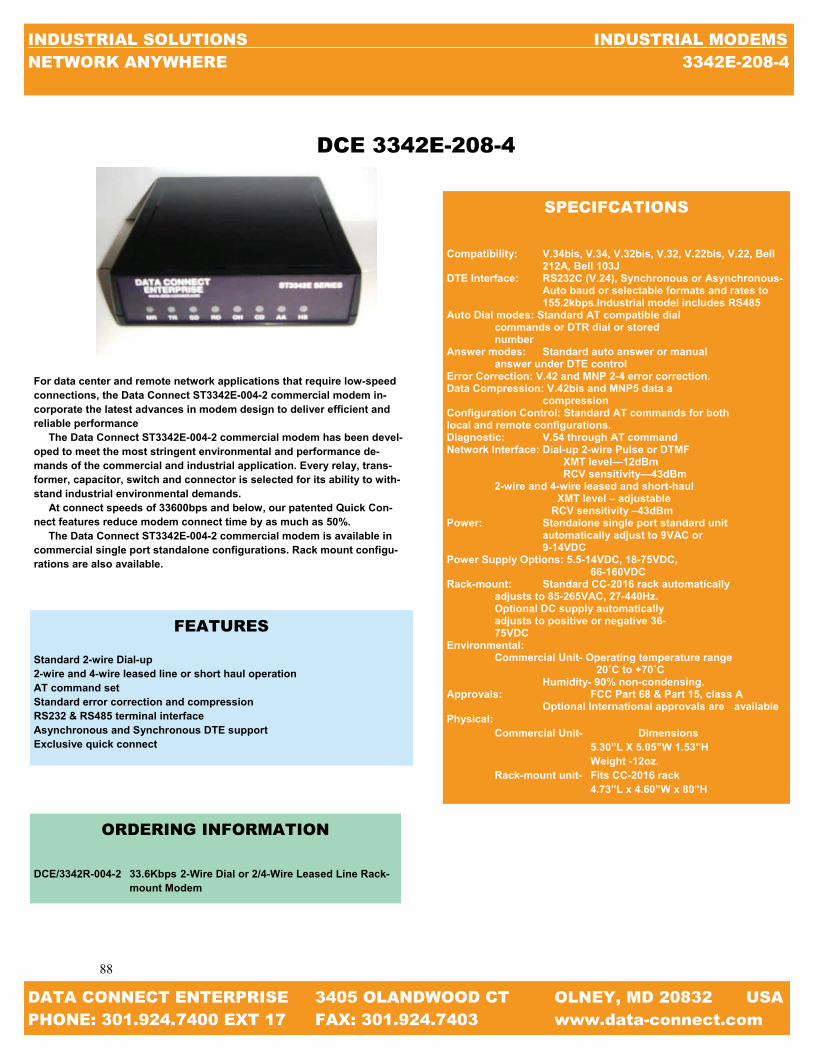
88
88
INDUSTRIAL SOLUTIONS INDUSTRIAL MODEMS NETWORK ANYWHERE 3342E-208-4
DATA CONNECT ENTERPRISE 3405 OLANDWOOD CT OLNEY, MD 20832 USA PHONE: 301.924.7400 EXT 17 FAX: 301.924.7403 www.data-connect.com
For data center and remote network applications that require low-speed connections, the Data Connect ST3342E-004-2 commercial modem in-corporate the latest advances in modem design to deliver efficient and reliable performance The Data Connect ST3342E-004-2 commercial modem has been devel-oped to meet the most stringent environmental and performance de-mands of the commercial and industrial application. Every relay, trans-former, capacitor, switch and connector is selected for its ability to with-stand industrial environmental demands. At connect speeds of 33600bps and below, our patented Quick Con-nect features reduce modem connect time by as much as 50%. The Data Connect ST3342E-004-2 commercial modem is available in commercial single port standalone configurations. Rack mount configu-rations are also available.
FEATURES
Standard 2-wire Dial-up 2-wire and 4-wire leased line or short haul operation AT command set Standard error correction and compression RS232 & RS485 terminal interface Asynchronous and Synchronous DTE support Exclusive quick connect
ORDERING INFORMATION
DCE/3342R-004-2 33.6Kbps 2-Wire Dial or 2/4-Wire Leased Line Rack- mount Modem
SPECIFCATIONS
Compatibility: V.34bis, V.34, V.32bis, V.32, V.22bis, V.22, Bell 212A, Bell 103J DTE Interface: RS232C (V.24), Synchronous or Asynchronous-
Auto baud or selectable formats and rates to 155.2kbps.Industrial model includes RS485
Auto Dial modes: Standard AT compatible dial commands or DTR dial or stored number Answer modes: Standard auto answer or manual answer under DTE control Error Correction: V.42 and MNP 2-4 error correction. Data Compression: V.42bis and MNP5 data a compression Configuration Control: Standard AT commands for both local and remote configurations. Diagnostic: V.54 through AT command Network Interface: Dial-up 2-wire Pulse or DTMF XMT level—12dBm RCV sensitivity—43dBm 2-wire and 4-wire leased and short-haul XMT level – adjustable RCV sensitivity –43dBm Power: Standalone single port standard unit automatically adjust to 9VAC or 9-14VDC Power Supply Options: 5.5-14VDC, 18-75VDC, 66-160VDC Rack-mount: Standard CC-2016 rack automatically adjusts to 85-265VAC, 27-440Hz. Optional DC supply automatically adjusts to positive or negative 36- 75VDC Environmental: Commercial Unit- Operating temperature range 20˚C to +70˚C Humidity- 90% non-condensing. Approvals: FCC Part 68 & Part 15, class A
Optional International approvals are available Physical:
Commercial Unit- Dimensions 5.30”L X 5.05”W 1.53”H Weight -12oz. Rack-mount unit- Fits CC-2016 rack 4.73”L x 4.60”W x 80”H
DCE 3342E-208-4

89
89
INDUSTRIAL SOLUTIONS INDUSTRIAL MODEMS NETWORK ANYWHERE MAIN MODEM CHART
DATA CONNECT ENTERPRISE 3405 OLANDWOOD CT OLNEY, MD 20832 USA PHONE: 301.924.7400 EXT 17 FAX: 301.924.7403 www.data-connect.com
NOTES:

90
90
INDUSTRIAL SOLUTIONS INDUSTRIAL MODEMS NETWORK ANYWHERE V.34 MODEM CHECK LIST
DATA CONNECT ENTERPRISE 3405 OLANDWOOD CT OLNEY, MD 20832 USA PHONE: 301.924.7400 EXT 17 FAX: 301.924.7403 www.data-connect.com
V.34 MODEM CHECK LIST
MODEL MAX.
SPEED HIGH VOLT.
LOW VOLT. DIAL LEASED
RACK MOUNT
DIN MOUNT
SECUR-ITY
WALL MOUNT PHOTO PAGE
DCE/MIU28.8 28.8KBPS X 91
DCE/MIUPP28.8 28.8KBPS X 92
DCE/MD28.8 28.8KBPS X X 93
DCE/PE28.8 28.8KBPS X 95

91
91
INDUSTRIAL SOLUTIONS INDUSTRIAL MODEMS NETWORK ANYWHERE MIU28.8
DATA CONNECT ENTERPRISE 3405 OLANDWOOD CT OLNEY, MD 20832 USA PHONE: 301.924.7400 EXT 17 FAX: 301.924.7403 www.data-connect.com
To service the growing need for efficient, reliable data communica-tion in a harsh environmental of utility substations and industrial facili-ties, has developed a 28800bps modem that can operate from various AC/DC power supplies and survive high surge levels and extreme heat and cold. All this without compromising the performance expected from state-of-the-art communications devices. With the rapid move toward “intelligent” substation, where meters relays, RTU’s, SCADA system, etc are able to “talk” to a remote opera-tor, communication devices such as modems moving off the desktop and into the field, where the convenience of 115VAC power outlets and climate control are usually hard to find. Data Connect Enterprise has addressed this problem by developing the MIU28.8 series modem designed specifically for harsh environ-ments. The MIU28.8 series modem is highly sophisticated full duplex, V.34 data modem that designed to interface with RS232, RS485 (external device), 5V logic (TTL) or simple send and receive signals The Miu28.8 series modem operates on a dial-up system. The MIU28.8 series modem is powered from unique power supply that enables it to operate on any AC or DC voltage ranging from 48V to 240V. A low voltage version (9-36VDC) is also available. The MIU28.8 modem is designed to work in temperatures from 40˚C to 85˚C and is surge protected on both the power and analog lines. The MIU28.8 series modem is bundled in a 5-3/8” x 1-3/8” non-metallic enclosure, suitable for desktop or wall mounting. Also see our Data sheets on the MIU/power-port low voltage mo-dems, the “Myriad” Rack Mount Modem, MIU (Bell), MIU14.4 and MIU9.6FPD modems
FEATURES Modem Interface Units AC/DC Powered Substation Hardened Communication Interface Units 28.8kbps 2-wire Dial Modem 48 to 220 AC/DC Power Supply IEC801-4 Surge Protection -40˚C to +85˚C Operating Temperature For Meters, Relay, SCADA etc.
SPECIFICATIONS Modem Line Speeds: Asynchronous 28800, 14400, 9600, 4800, 1200, 300bps DTE Rates: Above modem line speeds (IE; with data compression) 115.2, 57.6, 38.4 19.2kbps Standards: V.34, V.32bis, V.32, V.22bis, V.22, Bell 212A, and Bell 103 Transmission Line: Dial Compatibility: Hayes Extended AT command set Power Supply: 48VAC/DC to 220VAC/DC (Optional 9-36VDC) Power Connector: 4-ft AC Cord with 3-pin screw terminal connector included Case size: 5-3/8” x 4” x 1-3/8” Digital Port: RS232 withDB9 connector Analog Port: RJ11 Modular Jack Surge Protection: (power line) 8kV [exceeds IEC801-4] (20kV IE801-5 available if required) Surge Protection: 3.75VAC Environment: -40˚C to +85˚C, 0 to 95% humidity (non-condensing) Certifications: FCC Part 68, Industry Canada
ORDERING INFORMATION DCE/MIU-28.8 V.34 28.8Kbps2-Wire Dial Modem DCE/MIU-28.8LV V.34 28.8Kbps2-Wire Dial Modem Low Voltage
DCE MIU28.8

92
92
INDUSTRIAL SOLUTIONS INDUSTRIAL MODEMS NETWORK ANYWHERE MIU-PP288
DATA CONNECT ENTERPRISE 3405 OLANDWOOD CT OLNEY, MD 20832 USA PHONE: 301.924.7400 EXT 17 FAX: 301.924.7403 www.data-connect.com
SPECIFICATIONS Modem Line Speeds: Asynchronous 28800, 14400, 9600, 4800, 1200, 300bps DTE Rates: Above modem line speeds (IE; with data compression) 115.2, 57.6, 38.4 19.2kbps Standards: V.34, V.32bis, V.32, V.22bis, V.22, Bell 212A, and Bell 103 Transmission Line: Dial Compatibility: Hayes Extended AT command set Powered through the RS232 (DB25) data interface port or external jack (optional 7-16VDC available) Case size: 5-3/8” x 4” x 1-3/8” Digital Port: RS232 withDB9 connector Analog Port: RJ11 Modular Jack Surge Protection: (power line) 8kV [exceeds IEC801-4] (20kV IE801-5 available if required) Surge Protection: 3.75VAC Environment: -40˚C to +85˚C, 0 to 95% humidity (non-condensing)
Certifications: FCC Part 68, Industry Canada
ORDERING INFORMATION DCE/MIU-PP288 V.34 28.8Kbps2-Wire Dial Modem with 5VDC Power thru DB25
To service the growing need for efficient, reliable data communi-cation in a harsh environmental of utility substations and industrial facilities, has developed a 28800bps modem that can operate from various AC/DC power supplies and survive high surge levels and extreme heat and cold. All this without compromising the perform-ance expected from state-of-the-art communications devices. With the rapid move toward “intelligent” substation, where meters relays, RTU’s, SCADA system, etc are able to “talk” to a remote op-erator, communication devices such as modems moving off the desktop and into the field, where the convenience of 115VAC power outlets and climate control are usually hard to find. Data Connect Enterprise has addressed this problem by develop-ing the PowerPort-MIU28.8 series modem designed specifically for harsh environments. The PowerPort-MIU28.8 series modem is highly sophisticated full duplex, V.34 data modem that designed to interface with RS232, RS485 (external device), 5V logic (TTL) or simple send and receive signals The PowerPortMiu28.8 series modem operates on a dial-up system. The PowerPort-MIU28.8 series modem is powered from unique power supply that enables it to operate on any AC or DC voltage ranging from 48V to 240V. A low voltage version (9-36VDC) is also available. The PowerPortMIU28.8 modem is designed to work in tem-peratures from 40˚C to 85˚C and is surge protected on both the power and analog lines. The PowerPort-MIU28.8 series modem is bundled in a 5-3/8” x 1-3/8” non-metallic enclosure, suitable for desktop or wall mounting. Also see our Data sheets on the MIU/power-port low voltage mo-dems, the “Myriad” Rack Mount Modem, MIU202T (Bell), MIU9.6FPD, MIU14.4, and MIU28.8 modems.
DCE MIU-PP288
FEATURES Modem Interface Units AC/DC Powered Substation Hardened Communication Interface Units 28.8kbps 2-wire Dial Modem Powered through the RS232 (DB25) data interface port or External Jack (Optional 7-16VDC available) Automatic “Power Down” when inactive IEC801-4 Surge Protection -40˚C to +85˚C Operating Temperature Hayes AT compatible

93
93
INDUSTRIAL SOLUTIONS INDUSTRIAL MODEMS NETWORK ANYWHERE MD288
DATA CONNECT ENTERPRISE 3405 OLANDWOOD CT OLNEY, MD 20832 USA PHONE: 301.924.7400 EXT 17 FAX: 301.924.7403 www.data-connect.com
FEATURES 28.8kbps 2-wire Dial Line Modem IEC801-4 Surge Protection -20˚C to +85˚C Operating Temperature For Meters, Relays, SCADA, etc.
MD228 SPECIFICATIONS Modem Line Speeds Asynchronous 28800, 14000, 9600, 4800, 2400, 1200, 300bps DTE Rate Above modem line speeds (IE; with data compression 115.2, 57.6, 38.4, 19.2kbps Standards V.34, V.32bis, V.32, V.22bis, V.22, Bell 212A, Bell 103 Transmission Line 2-wire dial Compatibility Hayes Extended AT Command Set Digital Port RS232 with DB9 Connector Analog Port RJ11Modular Jack Surge Protection (Power Line) 8kV [Exceeds IEC801-4] (20kV IE801-5 (available if required) Surge Protection 3.75VAC Environment -40˚C to + 85˚C, 0 to 95% humidity (non-condensing) Certifications FCC Part 68, Industry Canada
The Data Connect MD28.8 is the Rack-mount version of the Data Connect MIU28. The same functionally that can be found in the MIU28.8 can be found in the MD14.4L. The Data Connect MD28.8 is a Bell V.32bis modem designed for asynchronous operation at 0 to 144400bps over voice grade lines. The modem is intended for use on 2-wire or 4-wire leased lines. The MD28.8 is comprised of MDMC carrier card and PE14.4 module. Up to 18 MD28.8 can be front loaded into MDR Modem Bank. The MDR Modem Bank is an industrial grade 19” X 3U rack mountable chassis. MDR Modem Bank is powered from a wide range of AC and DC voltages. Two power supply cards can be installed to provide automatic back up in the event the primary power supply fails. The MDR will operate in temperatures from -20˚C to + 85˚C and is surge protected on both power analog lines. Two power supply slots are provided. Power supply cards are available for any voltage in the range 9-150VDC and 9-275VAC. A single power supply card will power all 18 MD28.8. In additional to the MD28.8 the MDR Modem Bank also houses the MD14.4L, MD14.4, MD9.6FPD, and MD202T.
DCE MD288
ORDERING INFORMATION DCE/MD288 V.34 28.8Kbps2-Wire Dial Rackmount Modem

94
94
INDUSTRIAL SOLUTIONS INDUSTRIAL MODEMS NETWORK ANYWHERE MDR
DATA CONNECT ENTERPRISE 3405 OLANDWOOD CT OLNEY, MD 20832 USA PHONE: 301.924.7400 EXT 17 FAX: 301.924.7403 www.data-connect.com
DCE MDR
The Data Connect MDR Modem Chassis is designed to house eighteen (18) DCE MD Modem Cards and two (2) DCE MDP Power Supplies. The DCE MDR Modem Chassis is hardened industrial grade, 19” wide, 3U height (5.25”H), and constructed heavy gauge steel with plating for corrosion resistance. The DCE MD Modem Cards are comprised of a DCE MDMC Modem Carrier Card and a DCE PE OEM Card. The DCE MD202T (Bell 202T), MD9.6FPD (Proprietary), MD2.4 (V.22), MD14.4 (V.32bis), MD14.4L (V.32bis), and MD28.8 (V.34) operate within the DCE MDR Modem Chassis and are hot-swappable. Any mix of the DCE MD modems can be utilized simultaneously. Two (2) DCE MDP Power Supplies Cards provide full redundancy and are available for any voltage in the range of 9-150VDC and 9-275VAC. A single DCE MDP Power Supply Card powers eighteen (18) Modem Cards. A second DCE MDP Power Supply Card, if in-stalled, provides automatic backup in the event of a failure of the primary DCE MDP Power Supply Card.
FEATURES
18 Modem Slots Dial & Leased Line Modems V.22, 202T, 9.6FPD, V.32bis, V.34 Hayes AT Compatibility Full Array of LEDs Standard 19” x 5.25” (3U) Euro-Chassis AC or DC Power from 9 to 300VAC or VDC Dual Power Supplies with Full Redundancy Ideal for SCADA Master Stations
SPECIFICATIONS EIA Standards Compliant with EIA Standard EIA-310-C Modem Interface Connectors (Rear) Serial RS232: DB25F Analog Port: RJ11 LEDs (Front) (Top to bottom) DTR: Data Terminal Ready TXD: Transmit Data RXD: Receive Data MR: Modem Ready CD: Carrier Detect RTS: Request to Send CTS: Clear to Send RI: Ring Indicator Power Requirements AC Power: 9 to275VAC – Fused Socket (IEC 320) DC Power: 9 to 150VDC – Screw Terminals – 9 to 150VDC Dimensions Width: 19” Depth: Height: 5.25” (3U) Environmental Operating Temperature: -20 to +85 Degrees Celsius

95
95
INDUSTRIAL SOLUTIONS INDUSTRIAL MODEMS NETWORK ANYWHERE PE28.8
DATA CONNECT ENTERPRISE 3405 OLANDWOOD CT OLNEY, MD 20832 USA PHONE: 301.924.7400 EXT 17 FAX: 301.924.7403 www.data-connect.com
DCE PE28.8
To service the growing need for efficient, reliable data communica-tion in harsh environments of utility substations and industrial facili-ties, DCE has developed a series of OEM PCB modems that can op-erate at 5V logic (TTL) or simple send and receive signals and sur-vive high surge levels and extreme heat and cold. All this without compromising the performance expected from state-of-the-art com-munication devices. With the rapid move toward “intelligent” substa-tions, where meters, relays, RTUs, SCADA systems, etc. are able to “talk” to a remote operator, communication devices such as modems are moving off the desktop and into the meters, RTUs, and SCADA units where the conveniences of a standalone modem is unaccept-able. Data Connect Enterprise has addressed this problem by develop-ing the PE28.8 OEM modem designed specifically for harsh environ-ments. The PE 28.8 OEM modem is highly sophisticated full duplex, V.34 data modem that is designed to interface with RS232, RS485 (external device), 5V logic (TTL) or simple send and receive signals. The 28.8 OEM modem operates at full duplex on a dial up line.
FEATURES
Modem Interface Units 5V logic (TTL) Simple send and receive signals 2400kbps 2-wire dial-up line modem 5V logic (TTL) power supply IEC801-4 surge protection -40°C to +85°C operating temperature
SPECIFICATIONS
Modem Line Speeds: Asynchronous 28800, 14400, 9600, 4800, 2400, 1200, 300bps Standards: V.34, V.32bis, V.32, V.22bis, V.22, Bell 212A, and Bell 103 Transmission Line: Dial-up Compatibility: Hayes Extended AT Command Set Power: 5V logic (TTL) Card size: 3.4” x 0.01” x 0.5” Digital port: DTE 8-pin, simple send/receive signals Analog port: RJ11 modular jack Surge protection (Power line): 8kV (exceeds IEC801-4) (20kV [IE801-5] available if required) Surge protection (Analog line): 5kVAC Environment: -40°C to +85°C, 0-95% humidity (non condensing) Certifications: FCC part 68, industry Canada
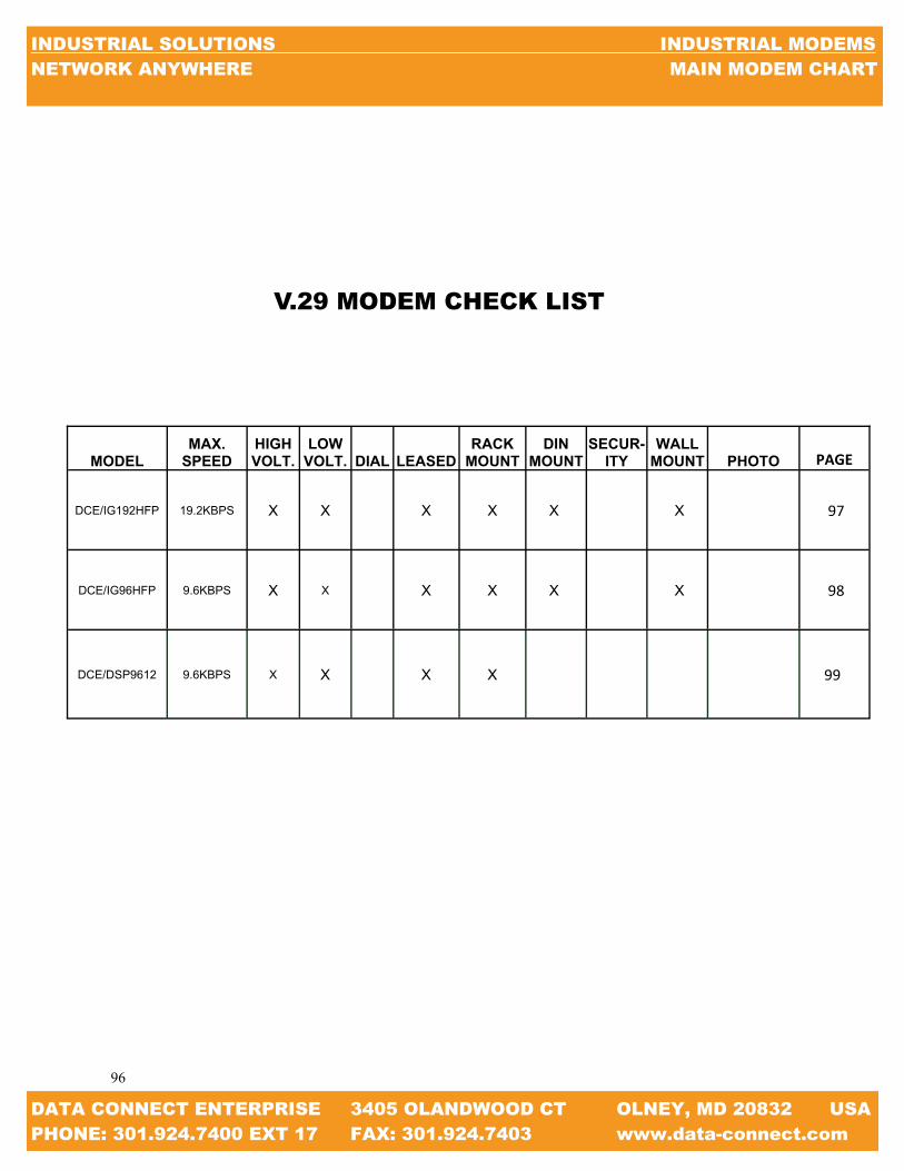
96
96
INDUSTRIAL SOLUTIONS INDUSTRIAL MODEMS NETWORK ANYWHERE MAIN MODEM CHART
DATA CONNECT ENTERPRISE 3405 OLANDWOOD CT OLNEY, MD 20832 USA PHONE: 301.924.7400 EXT 17 FAX: 301.924.7403 www.data-connect.com
MODEL MAX.
SPEED HIGH VOLT.
LOW VOLT. DIAL LEASED
RACK MOUNT
DIN MOUNT
SECUR-ITY
WALL MOUNT PHOTO PAGE
DCE/IG192HFP 19.2KBPS X X X X X X 97
DCE/IG96HFP 9.6KBPS X X X X X X 98
DCE/DSP9612 9.6KBPS X X X X 99
V.29 MODEM CHECK LIST

97
97
INDUSTRIAL SOLUTIONS INDUSTRIAL MODEMS NETWORK ANYWHERE IG192HFP
DATA CONNECT ENTERPRISE 3405 OLANDWOOD CT OLNEY, MD 20832 USA PHONE: 301.924.7400 EXT 17 FAX: 301.924.7403 www.data-connect.com
The IG192HFP industrial grade 19.2 kbps hyper fast poll modem is designed to operate over 4-wire full duplex or 2-wire half duplex uncondi-tional leased lines or private metallic circuits. For optimum performance, the modem employs QAM modulation and Viterbi decoding scheme along with its adaptive equalizer to communicate over a variety of transmission lines. The IG192HFP supports DTE/RTUs with an EIA RS-232 and RS-485 serial port at speeds of 19200, 9600, 4800, 2400 and 1200 bps. With its Auto-RTS mode, the modem can support DTE/RTUs with 3-wire serial interface (TD, RD, SG) in multi-point polling applications. The triple mode capability allows the IG192HFP industrial grade 19.2 kbps hyper fast poll modem to communicate with older generating DSP9612FP at up to 9600 kbps and both the Bell 202T and V.23 FSK mo-dems at up to 1200 bps. The IG192HFP industrial grade 19.2 kbps hyper fast poll modem is designed to operate over a wide range of AC or DC power supply voltages and temperatures. With proven reliability and ease of installations, the IG192HFP is deal for point-to-multipoint polling networks, where fast training time and low network latency are critical for system performance.
ORDERING INFORMATION
DCE/IG192HFP STANDALONE (100-240VAC) DCE/IG192HFP-LV STANDALONE (10-48 VDC )DCE/IG192HFP-HV STANDALONE (100-240 VAC, 85-400 VDC) DCE/IG192HFP-RM RM16M RACK-MOUNT MODULE DCE/192HFP-WMB WALL-MOUNT/PANEL-MOUNT KIT
SPECIFICATIONS TRIPLE MODE: Hyper Fast Poll mode at 19200bps. 17.4 ms RTS-CTS delay QAM mode at 9600/4800/2400bps. 23 ms RTS-CTS delay FSK mode for both Bell 202T (0-1800bps) and V23 (0-1200bps) DTE/RTU INTERFACE: RS-232 interface with full control signals support (DB-9F) RS-485/RS422 support, 4-wire F.D., or 2-wire H.D. Auto RTS and forced RTS options to support 3-wire interface LEASED LINE INTERFACE: TELCO 2- or 4- wire conditioned or unconditioned lines Private metallic 2 or 4 wire circuits Cable equalizers for long distance over standard cables MECHANICAL: Enclosure dimensions: 5.0” (W) x 6.75”( L) x 1.3” (H) 127mm (W) x 172mm (L) x 33mm (H) DIAGNOSTIC: Local or remote Analog + digital loopback eight (8) front panel LEDS for status monitoring AC and DC Power Support: Standalone: 10-48 VDC, 85-400 VDC, 100-240 AC Rack Mount Module: Plug-in RM16M modem rack ENVIRONMENTAL: Operating temperature: -40 to 85 Degrees Celsius Storage temperature: -40 to 100 Degrees Celsius Humidity: up to 95%, non-condensing OPTIONAL MOUNTING KITS: Wall-mount or panel mount kit DIN rail mounting kit POWER + CURRENT CONSUMPTION: 125 mA @ 12 VDC 28.0 mA @ 48 VDC
DCE IG192HFP

98
98
INDUSTRIAL SOLUTIONS INDUSTRIAL MODEMS NETWORK ANYWHERE IG96HFP
DATA CONNECT ENTERPRISE 3405 OLANDWOOD CT OLNEY, MD 20832 USA PHONE: 301.924.7400 EXT 17 FAX: 301.924.7403 www.data-connect.com
The IG96HFP industrial grade 9.6 kbps hyper fast modem is designed to operate over 4-wire full duplex or 2 wire half duplex unconditioned leased lines or private metallic circuits. For optimum performance, the modem em-ploys QAM modulations along with its adaptive equalizers to communicate over a variety of transmissions lines. The IG96HFP supports DTE/RTUs with an EIA RS-232 andRS-485 serial port at speeds of 9600, 4800, 2400 and 1200 bps. EIA its Auto-RTS mode, the modem can support DTE/RTUs with 3-wire serial interface (TD, RD, and SG) in multi-point polling applications. The triple mode capability allows the IG96HFP industrial grade 9.6 kbps hyper fast poll modem to communicate with the older generation DSP9612FP at up to 9600 kbps and both the Bell 202T and V.23 FSK modem at up to 1200 bps. The IG96HFP industrial grade 9.6 kbps hyper fast poll modem to range AC or DC power supply voltage and temperatures, with proven reliability and ease of installation, the IG96HFP is deal for point-to-multipoint polling networks, where fast training time and low-network latency are critical for system performance.
ORDERING INFORMATION
DCE/IG96HFP STANDALONE (100-240VAC) DCE/IG96HFP-LV STANDALONE (10-48 VDC) DCE/IG96HFP-HV STANDALONE (100-240 VAC, 85-400 VDC) DCE/IG96HFP-RM RM16M RACK-MOUNT MODULE DCE/96HFP-WMB WALL-MOUNT/PANEL-MOUNT KIT DCE/IG96HFP-DIN DIN RAIL MOUNTING KIT
SPECIFICATIONS
TRIPLE MODE: Hyper Fast Poll mode at 9600, 17.5 ms RTS-CTS delay QAM mode at 9600/4800/4200bps 23 ms RTS-CTS delay FSK mode for Bell 202T (0-1800) modes DTE/RTU INTERFACE: RS-232 interface with full control signals support (db-9F) RS-485/RS422 support, 4-wire F.D., or 2-wire H.D Auto RTS and forced RTS options to support 3-wire interface LEASED LINE INTERFACE: Telco 2- or 4- wire conditioned or unconditioned lines private metallic 2 or 4 wire circuits. Cable equalizer for long distance over standard cables MECHANICAL: Enclosure Dimensions: 5.0” (W) x 6.75” (L) x 1.3” (H). 127mm (W) x 172mm (L) x 33mm (H) DIAGNOSTICS: Local or remote Analog + digital loopback Eight (8) front panel LEDs for status monitoring AC and DC POWER SUPPORT: Standalone: 10-48 VDC, 85-400 VDC, 100-240 AC Rack Mount modules: Plug-in RM16M modem rack ENVIRONMENTAL: Operating temperatures:-40 to 85 degrees Celsius storage tem-perature:-40 to 100 degrees Celsius humidity: up to 95% non-condensing OPTIONAL MOUNTING KITS: Wall-mount or panel-mount kit DIN rail mounting kit POWER+ CURRENT CONSUMPTION: 125 mA @ 12 VDC 28.0 mA @ 48 VDC
DCE IG96HFP
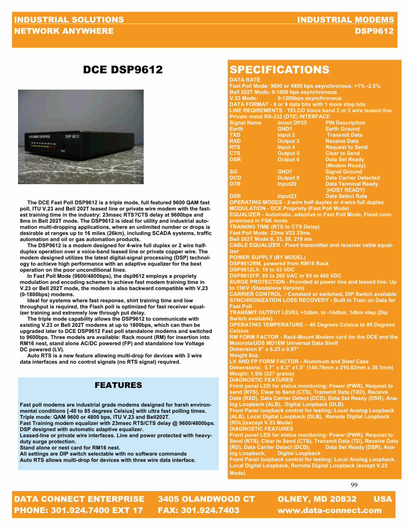
99
99
INDUSTRIAL SOLUTIONS INDUSTRIAL MODEMS NETWORK ANYWHERE DSP9612
DATA CONNECT ENTERPRISE 3405 OLANDWOOD CT OLNEY, MD 20832 USA PHONE: 301.924.7400 EXT 17 FAX: 301.924.7403 www.data-connect.com
DCE DSP9612
The DCE Fast Poll DSP9612 is a triple mode, full featured 9600 QAM fast poll, ITU V.23 and Bell 202T leased line or private wire modem with the fast-est training time in the industry: 23msec RTS?CTS delay at 9600bps and 8ms in Bell 202T mode. The DSP9612 is ideal for utility and industrial auto-mation multi-dropping applications, where an unlimited number or drops is desirable at ranges up to 16 miles (26km), including SCADA systems, traffic automation and oil or gas automation products. The DSP9612 is a modem designed for 4-wire full duplex or 2 wire half-duplex operation over a voice-band leased line or private copper wire. The modem designed utilizes the latest digital-signal processing (DSP) technol-ogy to achieve high performance with an adaptive equalizer for the best operation on the poor unconditional lines. In Fast Poll Mode (9600/4800bps), the dsp9612 employs a propriety modulation and encoding scheme to achieve fast modem training time in V.23 or Bell 202T mode, the modem is also backward compatible with V.23 (0-1800bps) modems. Ideal for systems where fast response, shirt training time and low throughput is required, the Flash poll is optimized for fast receiver equal-izer training and extremely low through put delay. The triple mode capability allows the DSP9612 to communicate with existing V.23 or Bell 202T modems at up to 1800bps, which can then be upgraded later to DCE DSP9612 Fast poll standalone modems and switched to 9600bps. Three models are available: Rack mount (RM) for insertion into RM16 nest, stand alone AC/DC powered (FP) and standalone low Voltage DC powered (LV). Auto RTS is a new feature allowing multi-drop for devices with 3 wire data interfaces and no control signals (no RTS signal) required.
FEATURES
Fast poll modems are industrial grade modems designed for harsh environ-mental conditions [-40 to 85 degrees Celsius] with ultra fast polling times. Triple mode: QAM 9600 or 4800 bps, ITU V.23 and Bell202T. Fast Training modem equalizer with 23msec RTS/CTS delay @ 9600/4800bps. DSP designed with automatic adaptive equalizer. Leased-line or private wire interfaces. Line and power protected with heavy-duty surge protection. Stand alone or nest card for RM16 nest. All settings are DIP switch selectable with no software commands Auto RTS allows multi-drop for devices with three wire data interface.
SPECIFICATIONS DATA RATE Fast Poll Mode: 9600 or 4800 bps asynchronous, +1% -2.5% Bell 202T Mode: 0-1800 bps asynchronous V.23 Mode: 0-1200bps asynchronous DATA FORMAT - 8 or 9 data bits with 1 more stop bits LINE REQIREMENTS - TELCO Voice band 2 or 2 wire leased line. Private metal RS-232 (DTE) INTERFACE Signal Name in/out DP25 PIN Description Earth GND1 Earth Ground TXD Input 2 Transmit Data RXD Output 3 Receive Data RTS Input 4 Request to Send CTS Output 5 Clear to Send DSR Output 6 Data Set Ready (Modem Ready) SG GND7 Signal Ground DCD Output 8 Data Carrier Detected DTR Input20 Data Terminal Ready (HOST READY) DSR Input23 Data Select Rate OPERATING MODES - 2-wire half duplex or 4-wire full duplex MODULATION - DCE Propriety (Fast Poll Mode) EQUALIZER - Automatic, adaptive in Fast Poll Mode, Fixed com-promised in FSK mode TRAINING TIME (RTS to CTS Delay) Fast Poll Mode: 23ms V23 33ms Bell 202T Mode:8, 33, 59, 219 ms CABLE EQUALIZER - Fixed transmitter and receiver cable equal-izer POWER SUPPLY (BY MODEL) DSP9612RM, powered from RM16 Rack DSP9612LV, 10 to 53 VDC DSP9612FP, 85 to 265 VAC or 85 to 400 VDC SURGE PROTECTION - Provided at power line and leased line; Up to 15KV (Standalone Version) CARRIER CONTROL - Constant or switched, DIP Switch available SYNCHRONIZATION LOSS RECOVERY - Built in Train on Data for Fast Poll TRANSMIT OUTPUT LEVEL +3dbm, to -14dbm, 1dbm step (Dip Switch available) OPERATING TEMPERATURE - -40 Degrees Celsius to 85 Degrees Celsius RM FORM FACTOR - Rack-Mount Modem card for the DCE and the Motorola/UDS MD16M Universal Data Shelf Dimension 9” x 6.25 x 0.87” Weight 8oz. LV AND FP FORM FACTOR - Aluminum and Steel Case Dimensions: 5.7” x 8.3” x1.5” (144.78mm x 210.82mm x 38.1mm) Weight: 1.9lb (227 grams) DIAGNOSTIC FEATURES Front panel LED for status monitoring: Power (PWR), Request to send (RTS), Clear to Send (CTS), Transmit Data (TXD), Receive Data (RXD), Data Carrier Detect (DCD), Data Set Ready (DSR), Ana-log Loopback (ALB), Digital Loopback (DLB) Front Panel loopback control for testing: Local Analog Loopback (ALB), Local Digital Loopback (DLB), Remote Digital Loopback (RDL)(except V.23 Mode) DIAGNOSTIC FEATURES Front panel LED for status monitoring: Power (PWR), Request to Send (RTS), Clear to Send (CTS), Transmit Data (TD), Receive Data (RD), Data Carrier Detect (DCD), Data Set Ready (DSR), Ana-log Loopback, Digital Loopback Front Panel loopback control for testing: Local Analog Loopback, Local Digital Loopback, Remote Digital Loopback (except V.23
Mode)

100
100
INDUSTRIAL SOLUTIONS INDUSTRIAL MODEMS NETWORK ANYWHERE V.32BIS MODEM CHECK LIST
DATA CONNECT ENTERPRISE 3405 OLANDWOOD CT OLNEY, MD 20832 USA PHONE: 301.924.7400 EXT 17 FAX: 301.924.7403 www.data-connect.com
V.32BIS MODEM CHECK LIST
MODEL MAX.
SPEED HIGH VOLT.
LOW VOLT. DIAL LEASED
RACK MOUNT
DIN MOUNT
SECUR-ITY
WALL MOUNT PHOTO PAGE
DCE/1442E-003-2 33.6KBPS X X X X 101
DCE/IG144 14.4KBPS X X X X X 102
DCE/IG144S 14.4KBPS X X X X X X 103
DCE/MIU14.4 14.4KBPS X X X
104
DCEMIUPP14.4 14.4KBPS X X X
105
DCE/MD14.4 14.4KBPS X X 106
DCE/PE14.4 14.4KBPS X 108
DCE/MIU14.4L 14.4KBPS X X X 109
DCE/MIUPP14.4L 14.4KBPS X X X 110
DCE/MD14.4L 14.4KBPS X X 111
DCE/PE14.4L 14.4KBPS X 113
DCE/1442E-203-3 14.4KBPS X
114
DCE/1442E-103-2 14.4KBPS X X
115
DCE/1442R-003-4 14.4KBPS X X X 116
DCE/1442E-503-2 14.4KBPS X X 117

101
101
INDUSTRIAL SOLUTIONS INDUSTRIAL MODEMS NETWORK ANYWHERE 1442E-003-2
DATA CONNECT ENTERPRISE 3405 OLANDWOOD CT OLNEY, MD 20832 USA PHONE: 301.924.7400 EXT 17 FAX: 301.924.7403 www.data-connect.com
For data center and remote network applications that require low-speed connections, the Data Connect ST1442E series modem incorporates the latest advance in modem design to deliver efficient and reliable perform-ance. The Data Connect ST1442E series modem has been developed to meet the most stringent environmental and performance demands of the commer-cial and industrial application. Every relay, transformer, capacitor, switch and connector is selected for its ability to withstand industrial environ-mental demands The industrial-rated Data Connect ST1442E may be housed in an optional metal enclosure and is built to meet the most stringent criteria. Temperature ratings, for example, range from -40˚C to + 85˚C versatile power supply op-tion will meet most industrial applications. At connect speeds of 14400bps and below, our patented quick Connect features reduce modem connect time by as much as 50% The Data Connect ST1442E series modem is available in commercial and industrial single-port standalone configurations. Rack mount configurations are also available.
FEATURES Standard 2-wire Dial-up 2-wire and 4-wire leased-line or short haul operation AT Command Set Standard Error Correction and Compression RS232 & RS485 Terminal Interfaces Asynchronous and Synchronous DTE Support Exclusive Quick Connect
SPECIFICATIONS Compatibility: V.32bis/V.32/V.22bis/V.22/Bell 212A/Bell 103J. DTE Interface: RS232C (V.24), synchronous or asynchronous auto baud or selectable formats and rates to 57.6kbps. Industrial model includes RS485 Auto Dial modes: Standard AT compatible dial commands or DTR dial or stored number Answer modes: Standard auto answer or manual answer under DTE control Error Correction: V.42 and MNP 2-4 error correction Data Compression: V.42bis and MNP5 data compression Configuration Control: Standard AT commands for both local and remote configurations. Diagnostic: V.54 through AT command Network Interface: Dial-up 2-wire Pulse or DTMF XMT level—12dBm RCV sensitivity—43dBm 2-wire and 4-wire leased and short-haul XMT level – adjustable RCV sensitivity –43dBm Power: Standalone single port standard unit automatically adjust to 9VAC or 9-14VDC Power Supply Options: 5.5-14VDC, 18-75VDC / 66-160VDC Rack-mount: Standard CC-2016 rack automatically adjusts to 85-265VAC, 27-440Hz. Optional DC supply: automatically adjusts to positive or negative 36-75VDC Environmental: Commercial Unit Operating temperature range 20˚C to +70˚C Humidity - 90% non-condensing Industrial Unit Operating temperature range 40˚C to +85˚C Humidity - 95% non-condensing Approvals: FCC Part 68 & Part 15, class A Optional International approvals are available. Physical: Commercial Unit Dimensions 5.30”L X 5.05”W 1.53”H Weight 12oz. Rackmount Unit Fits CC-2016 rack 4.73”L x 4.60”W x 80”H Weight 9oz. Industrial Unit Dimensions 6.190”L x 5.120”W 1.750”H Weight 32oz. (Metal Enclosure)
ORDERING INFORMATION DCE/1442E-003-2 Data Connect V32BIS 14.4KBPS Dial Modem
DCE 1442E-003-2

102
102
INDUSTRIAL SOLUTIONS INDUSTRIAL MODEMS NETWORK ANYWHERE IG144
DATA CONNECT ENTERPRISE 3405 OLANDWOOD CT OLNEY, MD 20832 USA PHONE: 301.924.7400 EXT 17 FAX: 301.924.7403 www.data-connect.com
The Data Connect DCE/IG144 high speed V.32bis dial-line modems are designed and manufactured for rugged industrial applications over the Public Switched Telephone Network (PSTN). The DCE/IG144 utilizes the industries latest V.32bis modem technology to deliver outstanding fea-tures, performance, and reliability in one cost-effective solution. The DCE/IG144 modems are ideally suited for industrial communica-tion application including SCADA systems, RTs, traffic monitor and con-trol, and industrial automation networks. The DCE/IG144 supports RTUs equipped with an EIA RS-232 or RS-485 serial port. Data communica-tions speeds up to 14.4 kbps in reception and up and up to 9.6 kbps in transmission are supported. The modems incorporate the latest data-compression and error-correction standards for improved data transmission and reception over marginal and poor-quality telephone lines. Multiple levels of security with password verification and security call back keep your valuable data secure from intruders. The DCE/IG144 modems are powered by wide range of AC and DC power supply voltage. Its low power consumption and low stand-by cur-rent technology design makes the DCE/IG144 ideal for a battery-powered system as well as regular AC powered operations.
FEATURES
Worldwide Operation Support: -ITU-T V.32bis/V.32/V.22bis/V.22/V.23/V.21/Bell 212A/Bell 103 -V29 FastPOS/V.22bis fast connect Data Compression: V.44/V.42bis/MNP 2 Error Correction: V.42/MNP 2/MNP 4 DTE/ Host Interface EIA RS-232 and RS-485 Embedded AT Command Set 63 embedded and upgradable country profiles for worldwide homologation NVRAM for configuration and country profile storage Built-in remote diagnostics and configuration management Heavy-duty surge protection provided at power supply and phone line interface Supports wide range of AC & DC power supply options Supports DC power supplied from DTE or DB-9 connector Wide range of operation temperatures Optional mounting kits for DIN rail mounting or wall mount
ORDERING INFORMATION
DCE/IG144 Standalone with AC power module, 90-264VAC DCEIG144DC Standalone, DC power, 10-48VDC DCE/IG144-HV Standalone with AC power module, 90-264VAC or 100-400VDC DCE/IG202T-DIN DCE EN2 Din Rail Kit
SPECIFICATIONS Data Modem: ITU-T V32bis: Up to 14.4kbps receive & 9.6kbps transit V.32: Up to 14400bps //V.32 Up to 9600 bps V.22bis: Up to 2400 bps V.21: 0-300 bps Bell 212A: 1200bps Bell 103: 0-300 Fax modem: Send and receive fax up to 14.4 kbps V17, V29, V27ter, and V21 channel 2 EIA/TIA 578 Class 1, T.31 Class 1.0, and Class 2 Data Format: Asynchronous, 7, 8 and 9 data bits parity, 10- or 11-bit char- acter with 1 or 2 stop bits Modulation: Fully compatible with ITU-T V.32bis/ V.22bis/V.21 Bell 212A and Bell 103 compatible Transmission Line Interface: 2-wire full duplex over PSTN connector RJ-11C DTE/RTU Interface The modem provides serial ports to supports RS-232 or RS-485 (selectable) interface standards: RS-232 Interface Connectors: DB9-F Signals: RTS, CTS, CD, TD, RD, DTR, DSR, RI RS-485 Interface Connector: RJ-11C Signals: 4-wire full duplex or 2-wire half duplex TX+, TX-, RX- and RX- LED Indicators: DTR, TXD, RXD, DCD, DSR, RI Power Supply Three models support various power options: Standalone - 90-264VAC Standalone - 100-400VDC Standalone - 10-48VDC Power Consumption: Idle mode - 65 mA@12V, 0.78watts Normal mode - 75 mA@12V, 0.9 watts, typical Mechanical Enclosure dimensions: 4.1” (W) x 5.0” (L) x 1.3” (H) 104mm (W) x 127mm (L) x 33mm (H) Weight: 0.5 pounds, without AC power module Environment Temperature: Operation - -40˚C to +85˚C Storage - -40˚C to +85˚C Humidity Up to 95% non-condensing Dry Contact Detection (optional) Two Optical isolated dry contact detection are provided for external devices (consult factory for additional information)
DCE IG144

103
103
INDUSTRIAL SOLUTIONS INDUSTRIAL MODEMS NETWORK ANYWHERE IG144S
DATA CONNECT ENTERPRISE 3405 OLANDWOOD CT OLNEY, MD 20832 USA PHONE: 301.924.7400 EXT 17 FAX: 301.924.7403 www.data-connect.com
The Data Connect DCE/IG144S high speed V.32bis dial-line modems are designed and manufactured for rugged industrial applications over the Public Switched Telephone Network (PSTN) with security features such as password log-in and security call-back. The DCE/IG144S utilizes the indus-tries latest V.32bis modem technology to deliver outstanding features, performance, and reliability in one cost-effective solution. The DCE/IG144S modems are ideally suited for industrial communica-tion application including SCADA systems, RTs, traffic monitor and con-trol, and industrial automation networks. The DCE/IG14S supports RTUs equipped with an EIA RS-232 or RS-485 serial port. Data communications speeds up to 14.4 kbps are supported. The modems incorporate the latest data-compression and error-correction standards for improved data transmission and reception over marginal and poor-quality telephone lines. Multiple levels of security with password verification and security call back keep your valuable data se-cure from intruders. The DCE/IG144S modems are powered by wide range of AC and DC power supply voltage. Its low power consumption and low stand-by current technology design makes the DCE/IG144S ideal for a battery-powered sys-tem as well as regular AC powered operations.
FEATURES
Worldwide Operation Support: -ITU-T V.32bis/V.32/V.22bis/V.22/V.23/V.21/Bell 212A/Bell 103 -V29 FastPOS/V.22bis fast connect/V.44/V.42bis/MNP 2/V.42/MNP 2/MNP 4 Security Options: Password log-in / Security call-back DTE/ Host Interface EIA RS-232 and RS-485 Embedded AT Command Set 63 embedded and upgradable country profiles for worldwide homologation NVRAM for configuration and country profile storage Built-in remote diagnostics and configuration management Heavy-duty surge protection provided at power supply and phone line interface Supports wide range of AC & DC power supply options Supports DC power supplied from DTE or DB-9 connector Wide range of operation temperatures Optional mounting kits for DIN rail mounting or wall mount
ORDERING INFORMATION
DCE/IG144S Standalone with AC power module, 90-264VAC DCEIG144SDC Standalone, DC power, 10-48VDC DCE/IG144-S-HV Standalone with AC power module, 90-264VAC or 100-400VDC DCE/IG202T-DIN DCE EN2 Din Rail Kit
SPECIFICATIONS Data Modem: ITU-T V32bis: Up to 14.4kbps receive & 9.6kbps transit V.32: Up to 14400bps V.32 Up to 9600 bps V.22bis: Up to 2400 bps V.21: 0-300 bps Bell 212A: 1200bps Bell 103: 0-300 Fax modem: Send and receive fax up to 14.4 kbps V17, V29, V27ter, and V21 channel 2 EIA/TIA 578 Class 1, T.31 Class 1.0, and Class 2 Data Format: Asynchronous, 7, 8 and 9 data bits parity, 10- or 11-bit character with 1 or 2 stop bits Modulation: Fully compatible with ITU-T V.32bis/ V.22bis/V.21 Bell 212A and Bell 103 compatible Transmission Line Interface: 2-wire full duplex over PSTN connector RJ-11C DTE/RTU Interface The modem provides serial ports to supports RS-232 or RS-485 (selectable) interface standards:RS-232 Interface Connectors - DB9-F Signals - RTS, CTS, CD, TD, RD, DTR, DSR, RI RS-485 Interface Connector - RJ-11C Signals - 4-wire full duplex or 2-wire half duplex TX+, TX-, RX- and RX- Front Panel Indicators LED Indicators: DTR, TXD, RXD, DCD, DSR, RI Security Options Password Log-in Security call-back Power Supply Three models support various power options: Standalone: 90-264VAC Standalone: 100-400VDC Standalone 10-48VDC Power Consumption: Idle mode: 65 mA@12V, 0.78watts Normal mode: 75 mA@12V, 0.9 watts, typical Mechanical Enclosure dimensions: 4.1” (W) x 5.0” (L) x 1.3” (H) 104mm (W) x 127mm (L) x 33mm (H) Weight: 0.5 pounds, without AC power module Environment Temperature: Operation - -40˚C to +85˚C Storage - -40˚C to +85˚C Humidity - Up to 95% non-condensing Dry Contact Detection (optional) Two Optical isolated dry contact detection are provided for external devices (consult factory for additional information)
DCE IG144S

104
104
INDUSTRIAL SOLUTIONS INDUSTRIAL MODEMS NETWORK ANYWHERE MIU-14.4
DATA CONNECT ENTERPRISE 3405 OLANDWOOD CT OLNEY, MD 20832 USA PHONE: 301.924.7400 EXT 17 FAX: 301.924.7403 www.data-connect.com
To service the growing need for efficient, reliable data communica-tion in harsh environments of utility substation and industrial facili-ties, has developed a 14400bps modem that can operate from various AC/DC power supplies and survive high surge levels and extreme heat and cold. All this without compromising the performance expected from state-of-the-art communications devices. With the rapid move toward “intelligent” substations, where me-ters, relays, RTUs, SCADA systems, etc. are able to “talk” to a remote operator, communication devices such as modems are moving off the desktop and into the field, where the convenience of 115VAC power outlets and climate control are usually hard to find. Data Connect Enterprise has addressed this problem by develop-ing the MIU14.4 series modem designed specifically for harsh environ-ments. The MIU14.4 series modem is highly sophisticated full duplex, V.32BIS data modem that designed to interface with RS232, RS485 (external device), 5V logic (TTL) or simple send and receive signals The MIU14.4 series modem operates on a dial-up line systems. The MIU14.4series modem is powered from unique power supply that enables it to operate on any AC or DC voltage ranging from 48V to 240V. A low voltage version (9-36VDC) is also available. The MIU14.4 modem is designed to work in temperatures from 40˚C to 85˚C and is surge protected on both the power and analog lines. The MIU14.4 series modem is bundled in a 5-3/8” x 1-3/8” non-metallic enclosure, suitable for desktop or wall mounting. Also see our Data sheets on the MIU/power-port low voltage mo-dems, the “Myriad” Rack Mount Modem, MIU202T (Bell), MIU28.8 and MIU9.6FPD modems
SPECIFICATIONS Modem Line Speeds: Asynchronous 14400, 9600, 4800, 1200, 300bps DTE Rates: Above modem line speeds (IE; with data compression) 57.6, 38.4 19.2kbps Standards: V.32bis, V.32, V.22bis, V.22, Bell 212A, and Bell 103 Transmission Line: 2-Wire Dial Compatibility: Hayes Extended AT command set Power Supply: 48VAC/DC to 220VAC/DC (Optional 9-36VDC) Power Connector: 4-ft AC Cord with 3-pin screw terminal connector included Case size: 5-3/8” x 4” x 1-3/8” Digital Port: RS232 withDB9 connector Analog Port: RJ11 Modular Jack Surge Protection: (power line) 8kV [exceeds IEC801-4] (20kV IE801-5 available if required) Surge Protection: 3.75VAC Environment: -40˚C to +85˚C, 0 to 95% humidity (non- condensing) Certifications: FCC Part 68, Industry Canada
ORDERING INFORMATION DCE/MIU-14.4 Data Connect V.32BIS, 14.4KBPS Dial Modem 48V-240V DCE/MIU-14.4LV Data Connect V.32BIS, 14.4KBPS Dial Modem 9– 36VDC
DCE MIU-14.4
FEATURES Modem Interface Units AC/DC Powered Substation Hardened Communication Interface Units 14.4kbps 2-wire Dial line modem 48 to 220 AC/DC Power Supply IEC801-4 Surge Protection -40˚C to +85˚C Operating Temperature For Meters, Relay, SCADA etc.

105
105
INDUSTRIAL SOLUTIONS INDUSTRIAL MODEMS NETWORK ANYWHERE MIU-PP14.4
DATA CONNECT ENTERPRISE 3405 OLANDWOOD CT OLNEY, MD 20832 USA PHONE: 301.924.7400 EXT 17 FAX: 301.924.7403 www.data-connect.com
To service the growing need for efficient, reliable data communica-tion in a harsh environmental of utility substations and industrial fa-cilities, has developed a 14400bps modem that can operate from vari-ous AC/DC power supplies and survive high surge levels and extreme heat and cold. All this without compromising the performance ex-pected from state-of-the-art communications devices. With the rapid move toward “intelligent” substation, where meters relays, RTU’s, SCADA system, etc are able to “talk” to a remote opera-tor, communication devices such as modems moving off the desktop and into the field, where the convenience of 115VAC power outlets and climate control are usually hard to find. Data Connect Enterprise has addressed this problem by develop-ing the PowerPortMIU14.4 series modem designed specifically for harsh environments. The PowerPortMIU14.4 series modem is highly sophisticated full duplex, V.32BIS data modem that designed to interface with RS232, RS485 (external device), 5V logic (TTL) or simple send and receive signals The PowerPortMIU14.4 series modem operates on a 2-Wire Dial-up system. The PowerPortMIU14.4 series modem is powered from unique power supply that enables it to operate on any AC or DC voltage rang-ing from 48V to 240V. A low voltage version (9-36VDC) is also avail-able. The PowerPortMIU14.4 modem is designed to work in tempera-tures from 40˚C to 85˚C and is surge protected on both the power and analog lines. The PowerPortMIU14.4 series modem is bundled in a 5-3/8” x 1-3/8” non-metallic enclosure, suitable for desktop or wall mounting. Also see our Data sheets on the MIU/power-port low voltage mo-dems, the “Myriad” Rack Mount Modem, MIU202T (Bell), MIU9.6FPD, MIU14.4, and MIU28.8 modems.
SPECIFICATIONS Modem Line Speeds: Asynchronous 14400, 9600, 4800, 1200, 300bps DTE Rates: Above modem line speeds (IE; with data compression) 57.6, 38.4 19.2kbps Standards: V.32bis, V.32, V.22bis, V.22, Bell 212A, and Bell 103 Transmission Line: Dial or 2&4 wire leased line Compatibility: Hayes Extended AT command set Powered through the RS232 (DB25) data interface port or external jack (optional 7- 16VDC available) Case size: 5-3/8” x 4” x 1-3/8” Digital Port: RS232 withDB9 connector Analog Port: RJ11 Modular Jack Surge Protection: (power line) 8kV [exceeds IEC801-4] (20kV IE801-5 available if required) Surge Protection: 3.75VAC Environment: -40˚C to +85˚C, 0 to 95% humidity (non-condensing) Certifications: FCC Part 68, Industry Canada
DCE MIU-PP14.4
ORDERING INFORMATON DCE/MIU-PP14.4 Data Connect V.32BIS 14.4 Dial Modem with 5VDC Power thru DB25
FEATURES Modem Interface Units AC/DC Powered Substation Hardened Communication Interface Units 14.4kbps 2&$ wire leased line modem Powered through the RS232 (DB25) data interface port or External Jack (Optional 7-16VDC available) Automatic “Power Down” when inactive IEC801-4 Surge Protection -40˚C to +85˚C Operating Temperature Hayes AT compatible Works with meters, Relays, SCADA, etc.

106
106
INDUSTRIAL SOLUTIONS INDUSTRIAL MODEMS NETWORK ANYWHERE MD14.4
DATA CONNECT ENTERPRISE 3405 OLANDWOOD CT OLNEY, MD 20832 USA PHONE: 301.924.7400 EXT 17 FAX: 301.924.7403 www.data-connect.com
DCE MD14.4
The Data Connect MD14.4 is the rack mount version of the Data Connect MIU14.4 and MIU14.4-LV. The same functionally that it can be found in the MIU14.4 and MIU14.4-LV can be found in the MD14.4. The Data Connect MD.14.4 is a Bell V.32bis modem designed for asyn-chronous operation at 0 to 14400bps over voice grade lines. The modem is intended for use on two-wire dial lines. The MD14.4 is comprised of MDMC carrier card and PE14.4 module. Up to 18 MD14.4 can be front loaded into a MDR Modem Bank. The MDR Modem Bank is an industrial grade 19” X 3U rack mountable chassis. The MDR Modem Bank is powered from a wide range of AC or DC voltages. Two power supply cards can be installed to provide automatic back up in the event the primary power supply fails. The MDR will operate in temperatures from -20˚C to +85˚C and is surge protected on both power and analog lines. Two power supply slots are provided. Power supply cards are available for any voltages in the range 9-150VDC and 9-275VAC. A single power sup-ply card will power all 18 MD14.4. In addition to MD14.4 the MDR Modem Bank also houses the MD28.8, MD14.4L, MD9.6FPD, and MD202T.
FEATURES 14.4kbps 2-Wire Dial line modem IEC801-4 surge protection -20˚C to +80˚C Operating Temperature Works with Meters, Relays, SCADA, etc.
SPECIFICATIONS Modem Line Speeds: Asynchronous 14000, 9600, 4800, 1200, 300bps DTE Rates: Above modem line speed (IE; with data compression 57.6, 38.4, 19.2kbps) Standards: V.32bis, V.32, V.22bis, V.22, Bell212A, and Bell 103 Transmission Line: 2-wire dial Compatibility: Hayes Extended AT Command Set Digital Port: RS232 with DB9 connector Analog Port: RJ11 Modular Jack Surge Protection: (Power Line) 8kV [Exceeds IE801-4] (20Kv IE801-5 available if required) Surge Protection 3.75VAC Environment: -40˚C or + 85˚C, 0 to 95% humidity (non-condensing) Certification: FCC Part 68, Industry Canada
ORDERING INFORMATION
DCE/MD14.4 Data Connect V.32bis, 14.4Kbps Rackmount Modem DCE/PE14.4 Data Connect V.32bis, 14.4Kbps OEM (PCB) Modem

107
107
INDUSTRIAL SOLUTIONS INDUSTRIAL MODEMS NETWORK ANYWHERE MDR
DATA CONNECT ENTERPRISE 3405 OLANDWOOD CT OLNEY, MD 20832 USA PHONE: 301.924.7400 EXT 17 FAX: 301.924.7403 www.data-connect.com
DCE MDR
The Data Connect MDR Modem Chassis is designed to house eighteen (18) DCE MD Modem Cards and two (2) DCE MDP Power Supplies. The DCE MDR Modem Chassis is hardened industrial grade, 19” wide, 3U height (5.25”H), and constructed heavy gauge steel with plating for corrosion resistance. The DCE MD Modem Cards are comprised of a DCE MDMC Modem Carrier Card and a DCE PE OEM Card. The DCE MD202T (Bell 202T), MD9.6FPD (Proprietary), MD2.4 (V.22), MD14.4 (V.32bis), MD14.4L (V.32bis), and MD28.8 (V.34) operate within the DCE MDR Modem Chassis and are hot-swappable. Any mix of the DCE MD modems can be utilized simultaneously. Two (2) DCE MDP Power Supplies Cards provide full redundancy and are available for any voltage in the range of 9-150VDC and 9-275VAC. A single DCE MDP Power Supply Card powers eighteen (18) Modem Cards. A second DCE MDP Power Supply Card, if in-stalled, provides automatic backup in the event of a failure of the primary DCE MDP Power Supply Card.
FEATURES
18 Modem Slots Dial & Leased Line Modems V.22, 202T, 9.6FPD, V.32bis, V.34 Hayes AT Compatibility Full Array of LEDs Standard 19” x 5.25” (3U) Euro-Chassis AC or DC Power from 9 to 300VAC or VDC Dual Power Supplies with Full Redundancy Ideal for SCADA Master Stations
SPECIFICATIONS EIA Standards Compliant with EIA Standard EIA-310-C Modem Interface Connectors (Rear) Serial RS232: DB25F Analog Port: RJ11 LEDs (Front) (Top to bottom) DTR: Data Terminal Ready TXD: Transmit Data RXD: Receive Data MR: Modem Ready CD: Carrier Detect RTS: Request to Send CTS: Clear to Send RI: Ring Indicator Power Requirements AC Power: 9 to275VAC – Fused Socket (IEC 320) DC Power: 9 to 150VDC – Screw Terminals – 9 to 150VDC Dimensions Width: 19” Depth: Height: 5.25” (3U) Environmental Operating Temperature: -20 to +85 Degrees Celsius

108
108
INDUSTRIAL SOLUTIONS INDUSTRIAL MODEMS NETWORK ANYWHERE PE14.4
DATA CONNECT ENTERPRISE 3405 OLANDWOOD CT OLNEY, MD 20832 USA PHONE: 301.924.7400 EXT 17 FAX: 301.924.7403 www.data-connect.com
DCE/PE14.4
To service the growing need for efficient, reliable data communication in harsh environments of utility substations and industrial facilities, DCE has developed a series of OEM PCB modems that can operate at 5V logic (TTL) or simple send and receive signals and survive high surge levels and extreme heat and cold. All this without compromising the performance expected from state-of-the-art communication de-vices. With the rapid move toward “intelligent” substations, where me-ters, relays, RTUs, SCADA systems, etc. are able to “talk” to a remote operator, communication devices such as modems are moving off the desktop and into the meters, RTUs, and SCADA units where the con-veniences of a standalone modem is unacceptable. Data Connect Enterprise has addressed this problem by developing the PE14.4 OEM modem designed specifically for harsh environments. The PE14.4 OEM modem is highly sophisticated full duplex, V.32bis data modem that is designed to interface with RS232, RS485 (external device), 5V logic (TTL) or simple send and receive signals. The PE14.4 OEM modem operates at full duplex on a dial up line. The PE 14.4 PCB can be found in the MIU14.4 modem, MD14.4 modem card, and the MIU-PP14.4 modem.
ORDERING INFORMATION DCE/PE14.4 Data Connect V.32bis, 14.4Kbps OEM (PCB) Modem
FEATURES Modem Interface Units 5V logic (TTL) Simple send and receive signals 14400kbps 2-wire dial-up line modem 5V logic (TTL) power supply IEC801-4 surge protection -40°C to +85°C operating temperature For meters, relays, SCADA etc.
SPECIFICATIONS Modem Line Speeds: Asynchronous 14000, 9600, 4800, 2400, 1200, 300bps Standards: V.32bis, V.32, V.22bis, Bell 212A, Bell 103 Transmission line: Dial-up Compatibility: Hayes Extended AT Command Set Power: 5V logic (TTL) Card size: 3.4” x 0.01” x 0.5” Digital port: DTE 8-pin, simple send/receive signals Analog port: RJ11 modular jack Surge protection (Power line): 8kV (exceeds IEC801-4) (20kV [IE801-5] available if re-quired) Surge protection (Analog line): 5kVAC Environment: -40°C to +85°C, 0-95% humidity (non condensing) Certifications: FCC part 68, industry Canada

109
109
INDUSTRIAL SOLUTIONS INDUSTRIAL MODEMS NETWORK ANYWHERE MIU14.4L
DATA CONNECT ENTERPRISE 3405 OLANDWOOD CT OLNEY, MD 20832 USA PHONE: 301.924.7400 EXT 17 FAX: 301.924.7403 www.data-connect.com
To service the growing need for efficient, reliable data communication in harsh environments of utility substation and industrial facilities, has devel-oped a 14400bps modem that can operate from various AC/DC power sup-plies and survive high surge levels and extreme heat and cold. All this with-out compromising the performance expected from state-of-the-art communi-cations devices. With the rapid move toward “intelligent” substations, where meters, re-lays, RTUs, SCADA systems, etc. are able to “talk” to a remote operator, communication devices such as modems are moving off the desktop and into the field, where the convenience of 115VAC power outlets and climate control are usually hard to find. Data Connect Enterprise has addressed this problem by developing the MIU14.4 series modem designed specifically for harsh environments. The MIU14.4 series modem is highly sophisticated full duplex, V.32BIS data modem that designed to interface with RS232, RS485 (external device), 5V logic (TTL) or simple send and receive signals The MIU14.4L series mo-dem operates on 2-wire and 4-wire leased line systems. The MIU14.4 series modem is powered from unique power supply that enables it to operate on any AC or DC voltage ranging from 48V to 240V. A low voltage version (9-36VDC) is also available. The MIU14.4 series modem is designed to work in temperatures from 40˚C to 85˚C and is surge pro-tected on both the power and analog lines. The MIU14.4 series modem is bundled in a 5-3/8” x 1-3/8” non-metallic enclosure, suitable for desktop or wall mounting. Also see our Data sheets on the MIU/power-port low voltage modems, the “Myriad” Rack Mount Modem, MIU202T (Bell), MIU28.8 and MIU9.6FPD mo-
FEATURES
Modem Interface Units AC/DC Powered Substation Hardened Communication Interface Units 14.4kbps 2 & 4-wire leased line modem 48 to 220 AC/DC Power Supply IEC801-4 Surge Protection -40˚C to +85˚C Operating Temperature For Meters, Relay, SCADA etc.
SPECIFICATIONS Modem Line Speeds: Asynchronous 14400, 9600, 4800, 1200, 300bps DTE Rates: Above modem line speeds (IE; with data compression) 57.6, 38.4 19.2kbps Standards: V.32bis, V.32, V.22bis, V.22, Bell 212A, and Bell 103 Transmission Line: 2 & 4-wire leased line Compatibility: Hayes Extended AT command set Power Supply: 48VAC/DC to 220VAC/DC (Optional 9-36VDC) Power Connector: 4-ft AC Cord with 3-pin screw terminal connector included Case size: 5-3/8” x 4” x 1-3/8” Digital Port: RS232 with DB9 connector Analog Port: RJ11 Modular Jack Surge Protection: (power line) 8kV [exceeds IEC801-4] (20kV IE801-5 available if required) Surge Protection: 3.75VAC Environment: -40˚C to +85˚C, 0 to 95% humidity (non- condensing) Certifications: FCC Part 68, Industry Canada
DCE MIU14.4L

110
110
INDUSTRIAL SOLUTIONS INDUSTRIAL MODEMS NETWORK ANYWHERE MIU-PP14.4L
DATA CONNECT ENTERPRISE 3405 OLANDWOOD CT OLNEY, MD 20832 USA PHONE: 301.924.7400 EXT 17 FAX: 301.924.7403 www.data-connect.com
To service the growing need for efficient, reliable data communication in a harsh environmental of utility substations and industrial facilities, has developed a 14400bps modem that can operate from various AC/DC power supplies and survive high surge levels and extreme heat and cold. All this without compromising the performance expected from state-of-the-art com-munications devices. With the rapid move toward “intelligent” substation, where meters relays, RTU’s, SCADA system, etc are able to “talk” to a remote operator, communi-cation devices such as modems moving off the desktop and into the field, where the convenience of 115VAC power outlets and climate control are usually hard to find. Data Connect Enterprise has addressed this problem by developing the PowerPortMIU14.4 series modem designed specifically for harsh environ-ments. The PowerPortMIU14.4L series modem is highly sophisticated full du-plex, V.32BIS data modem that designed to interface with RS232, RS485 (external device), 5V logic (TTL) or simple send and receive signals The PowerPortMIU14.4L series modem operates on a 2 or 4-Wire Leased Line and Short Haul systems. The PowerPortMIU14.4L series modem is powered from unique power supply that enables it to operate on any AC or DC voltage ranging from 48V to 240V. A low voltage version (9-36VDC) is also available. The PowerPort-MIU14.4L modem is designed to work in temperatures from 40˚C to 85˚C and is surge protected on both the power and analog lines. The PowerPortMIU14.4L series modem is bundled in a 5-3/8” x 1-3/8” non-metallic enclosure, suitable for desktop or wall mounting. Also see our Data sheets on the MIU/power-port low voltage modems, the “Myriad” Rack Mount Modem, MIU202T (Bell), MIU9.6FPD, MIU14.4, and MIU28.8 modems.
FEATURES
Modem Interface Units AC/DC Powered Substation Hardened Communication Interface Units 14.4kbps 2 or 4-Wire Leased Line modem Powered through the RS232 (DB25) data interface port or Ex-ternal Jack (Optional 7-16VDC available) Automatic “Power Down” when inactive IEC801-4 Surge Protection -40˚C to +85˚C Operating Temperature Hayes AT compatible
Specifications Modem Line Speeds: Asynchronous 14400, 9600, 4800, 1200, 300bps DTE Rates: Above modem line speeds (IE; with data compres-sion) 57.6, 38.4 19.2kbps Standards: V.32bis, V.32, V.22bis, V.22, Bell 212A, and Bell 103 Transmission Line: Dial or 2&4 wire leased line Compatibility: Hayes Extended AT command set Powered through the RS232 (DB25) data interface port or external jack (optional 7- 16VDC available) Case size: 5-3/8” x 4” x 1-3/8” Digital Port: RS232 withDB9 connector Analog Port: RJ11 Modular Jack Surge Protection: (power line) 8kV [exceeds IEC801-4] (20kV IE801-5 available if required) Surge Protection: 3.75VAC Environment: -40˚C to +85˚C, 0 to 95% humidity (non-condensing) Certifications: FCC Part 68, Industry Canada
DCE MIU-PP14.4L

111
111
INDUSTRIAL SOLUTIONS INDUSTRIAL MODEMS NETWORK ANYWHERE MD14.4L
DATA CONNECT ENTERPRISE 3405 OLANDWOOD CT OLNEY, MD 20832 USA PHONE: 301.924.7400 EXT 17 FAX: 301.924.7403 www.data-connect.com
DCE MD14.4L
The Data Connect MD14.4L is the rack mount version of the Data Connect MIU14.4L and MIU14.4-LV. The same functionally that it can be found in the MIU14.4L and MIU14.4-LV can be found in the MD14.4L. The Data Connect MD.14.4L is a Bell V.32bis modem designed for asyn-chronous operation at 0 to 14400bps over voice grade lines. The modem is intended for use on two or four wire Leased Lines. The MD14.4L is comprised of MDMC carrier card and PE14.4L module. Up to 18 MD14.4L can be front loaded into a MDR Modem Bank. The MDR Modem Bank is an industrial grade 19” X 3U rack mountable chassis. The MDR Modem Bank is powered from a wide range of AC or DC voltages. Two power supply cards can be installed to provide automatic back up in the event the primary power supply fails. The MDR will operate in temperatures from -20˚C to +85˚C and is surge protected on both power and analog lines. Two power supply slots are provided. Power supply cards are available for any voltages in the range 9-150VDC and 9-275VAC. A single power sup-ply card will power all 18 MD14.4L. In addition to MD14.4L the MDR Modem Bank also houses the MD28.8, MD14.4, MD9.6FPD, and MD202T.
FEATURES 14.4kbps 2 or 4-wire Leased Line modem IEC801-4 surge protection -20˚C to +80˚C Operating Temperature Works with Meters, Relays, SCADA, etc.
SPECIFICATIONS DTE Rates: Asynchronous 14000, 9600, 4800, 1200, 300bps Standards: V.32bis, V.32, V.22bis, V.22, Bell212A, and Bell 103 Transmission Line: 2- and 4-wire leased line Compatibility: Hayes Extended AT Command Set Digital Port: RS232 with DB9 connector Analog Port: RJ11 Modular Jack Surge Protection: (Power Line) 8kV [Exceeds IE801-4] (20Kv IE801-5 available if required) Surge Protection 3.75VAC Environment: -40˚C or + 85˚C, 0 to 95% humidity (non-condensing) Certification: FCC Part 68, Industry Canada

112
112
INDUSTRIAL SOLUTIONS INDUSTRIAL MODEMS NETWORK ANYWHERE MDR
DCE MDR
The Data Connect MDR Modem Chassis is designed to house eighteen (18) DCE MD Modem Cards and two (2) DCE MDP Power Supplies. The DCE MDR Modem Chassis is hardened industrial grade, 19” wide, 3U height (5.25”H), and constructed heavy gauge steel with plating for corrosion resistance. The DCE MD Modem Cards are comprised of a DCE MDMC Modem Carrier Card and a DCE PE OEM Card. The DCE MD202T (Bell 202T), MD9.6FPD (Proprietary), MD2.4 (V.22), MD14.4 (V.32bis), MD14.4L (V.32bis), and MD28.8 (V.34) operate within the DCE MDR Modem Chassis and are hot-swappable. Any mix of the DCE MD modems can be utilized simultaneously. Two (2) DCE MDP Power Supplies Cards provide full redundancy and are available for any voltage in the range of 9-150VDC and 9-275VAC. A single DCE MDP Power Supply Card powers eighteen (18) Modem Cards. A second DCE MDP Power Supply Card, if in-stalled, provides automatic backup in the event of a failure of the primary DCE MDP Power Supply Card.
FEATURES
18 Modem Slots Dial & Leased Line Modems V.22, 202T, 9.6FPD, V.32bis, V.34 Hayes AT Compatibility Full Array of LEDs Standard 19” x 5.25” (3U) Euro-Chassis AC or DC Power from 9 to 300VAC or VDC Dual Power Supplies with Full Redundancy Ideal for SCADA Master Stations
SPECIFICATIONS EIA Standards Compliant with EIA Standard EIA-310-C Modem Interface Connectors (Rear) Serial RS232: DB25F Analog Port: RJ11 LEDs (Front) (Top to bottom) DTR: Data Terminal Ready TXD: Transmit Data RXD: Receive Data MR: Modem Ready CD: Carrier Detect RTS: Request to Send CTS: Clear to Send RI: Ring Indicator Power Requirements AC Power: 9 to275VAC – Fused Socket (IEC 320) DC Power: 9 to 150VDC – Screw Terminals – 9 to 150VDC Dimensions Width: 19” Depth: Height: 5.25” (3U) Environmental Operating Temperature: -20 to +85 Degrees Celsius
DATA CONNECT ENTERPRISE 3405 OLANDWOOD CT OLNEY, MD 20832 USA PHONE: 301.924.7400 EXT 17 FAX: 301.924.7403 www.data-connect.com

113
113
INDUSTRIAL SOLUTIONS INDUSTRIAL MODEMS NETWORK ANYWHERE PE14.4
DATA CONNECT ENTERPRISE 3405 OLANDWOOD CT OLNEY, MD 20832 USA PHONE: 301.924.7400 EXT 17 FAX: 301.924.7403 www.data-connect.com
DCE PE14.4
To service the growing need for efficient, reliable data communication in harsh environments of utility substations and industrial facilities, DCE has developed a series of OEM PCB modems that can operate at 5V logic (TTL) or simple send and receive signals and survive high surge levels and extreme heat and cold. All this without compromising the performance expected from state-of-the-art communication de-vices. With the rapid move toward “intelligent” substations, where me-ters, relays, RTUs, SCADA systems, etc. are able to “talk” to a remote operator, communication devices such as modems are moving off the desktop and into the meters, RTUs, and SCADA units where the con-veniences of a standalone modem is unacceptable. Data Connect Enterprise has addressed this problem by developing the PE14.4L OEM modem designed specifically for harsh environments. The PE14.4L OEM modem is highly sophisticated full duplex, V.32bis data modem that is designed to interface with RS232, RS485 (external device), 5V logic (TTL) or simple send and receive signals. The PE14.4L OEM modem operates at half and full duplex 2 & 4-Wire Leased Lins. The PE 14.4L PCB can be found in the MIU14.4 modem, MD14.4 modem card, and the MIU-PP14.4 modem.
ORDERING INFORMATION DCE/PE14.4 Data Connect V.32bis, 14.4Kbps OEM (PCB) Modem
FEATURES Modem Interface Units 5V logic (TTL) Simple send and receive signals 14400kbps 2-wire dial-up line modem 5V logic (TTL) power supply IEC801-4 surge protection -40°C to +85°C operating temperature For meters, relays, SCADA etc.
SPECIFICATIONS Modem Line Speeds: Asynchronous 14000, 9600, 4800, 2400, 1200, 300bps Standards: V.32bis, V.32, V.22bis, Bell 212A, Bell 103 Transmission line: 2 or 4-Wire Leased Lines Compatibility: Hayes Extended AT Command Set Power: 5V logic (TTL) Card size: 3.4” x 0.01” x 0.5” Digital port: DTE 8-pin, simple send/receive signals Analog port: RJ11 modular jack Surge protection (Power line): 8kV (exceeds IEC801-4) (20kV [IE801-5] available if re-quired) Surge protection (Analog line): 5kVAC Environment: -40°C to +85°C, 0-95% humidity (non condensing) Certifications: FCC part 68, industry Canada

114
114
INDUSTRIAL SOLUTIONS INDUSTRIAL MODEMS NETWORK ANYWHERE 1442E-203-2
DATA CONNECT ENTERPRISE 3405 OLANDWOOD CT OLNEY, MD 20832 USA PHONE: 301.924.7400 EXT 17 FAX: 301.924.7403 www.data-connect.com
FEATURES
Standard 2-wire Dial-up 2-wire dial operation AT Command Set Standard Error Correction and Compression RS232 & RS485 Terminal Interfaces Asynchronous and Synchronous DTE Support
ORDERING INFORMATION DCE/1442E-203-2 Data Connect V32BIS 14.4KBPS Dial Modem
SPECIFICATIONS
Compatibility: V.32bis, V.32, V.22bis, V.22, Bell 212A, Bell 103J. DTE Interface: RS232C (V.24), synchronous or asynchronous auto baud or selectable formats and rates to 57.6kbps. Industrial model includes RS485 Auto Dial modes: Standard AT compatible dial commands or DTR dial or stored number Answer modes: Standard auto answer or manual answer under DTE control Error Correction: V.42 and MNP 2-4 error correction Data Compression: V.42bis and MNP5 data compression Configuration Control: Standard AT commands for both local and remote configurations. Diagnostic: V.54 through AT command Network Interface: Dial-up 2-wire Pulse or DTMF XMT level—12dBm RCV sensitivity—43dBm 2-wire and 4-wire leased and short-haul XMT level – adjustable RCV sensitivity –43dBm Power: Standalone single port standard unit automatically adjust to 9VAC or 9-14VDC Power Supply Options: 5.5-14VDC, 18-75VDC / 66-160VDC Rack-mount: Standard CC-2016 rack automatically adjusts to 85-265VAC, 27-440Hz. Optional DC supply: Automatically adjusts to positive or negative 36-75VDC Environmental: Commercial Unit Operating temperature range 20˚C to +70˚C Humidity 90% non-condensing Industrial Unit Operating temperature range 40˚C to +85˚C Humidity 95% non-condensing Approvals: FCC Part 68 & Part 15, class A Optional International approvals are available. Physical: Commercial Unit Dimensions 5.30”L X 5.05”W 1.53”H Weight 12oz. Rackmount Unit Fits CC-2016 rack 4.73”L x 4.60”W x 80”H Weight 9oz. Industrial Unit Dimensions 6.190”L x 5.120”W 1.750”H Weight
DCE 1442E-203-2
For data center and remote network applications that require low-speed connections, the Data Connect ST1442E-203-2 mo-dem incorporates the latest advance in modem design to deliver efficient and reliable performance. The Data Connect ST1442E-203-2 modem has been devel-oped to meet the most stringent environmental and performance demands of the commercial and industrial application. Every relay, transformer, capacitor, switch and connector is selected for its ability to withstand industrial environmental demands The industrial-rated Data Connect ST1442E-203-2 modem may be housed in an optional metal enclosure and is built to meet the most stringent criteria. Temperature ratings, for exam-ple, range from -40˚C to + 85˚C versatile power supply option will meet most industrial applications. At connect speeds of 14400bps and below, our patented quick Connect features reduce modem connect time by as much as 50% The Data Connect ST1442E-203-2 modem is available in com-mercial and industrial single-port standalone configurations. Rack mount configurations are also available.

115
115
INDUSTRIAL SOLUTIONS INDUSTRIAL MODEMS NETWORK ANYWHERE 1442E-103-2
DATA CONNECT ENTERPRISE 3405 OLANDWOOD CT OLNEY, MD 20832 USA PHONE: 301.924.7400 EXT 17 FAX: 301.924.7403 www.data-connect.com
DCE 1442E-103-2
For data center and remote network applications that require low-speed connections, the Data Connect ST1442E-103-2 mo-dem incorporates the latest advance in modem design to deliver efficient and reliable performance. The Data Connect ST1442E-103-2 modem has been devel-oped to meet the most stringent environmental and performance demands of the commercial and industrial application. Every relay, transformer, capacitor, switch and connector is selected for its ability to withstand industrial environmental demands The industrial-rated Data Connect ST1442E-103-2 modem may be housed in an optional metal enclosure and is built to meet the most stringent criteria. Temperature ratings, for exam-ple, range from -40˚C to + 85˚C versatile power supply option will meet most industrial applications. At connect speeds of 14400bps and below, our patented quick Connect features reduce modem connect time by as much as 50% The Data Connect ST1442E-103-2 modem is available in com-mercial and industrial single-port standalone configurations. Rack mount configurations are also available.
FEATURES
Standard 2-wire Dial-up 2-Wire dial operation AT Command Set Standard Error Correction and Compression RS232 & RS485 Terminal Interfaces Asynchronous and Synchronous DTE Support
ORDERING INFORMATION DCE/1442E-103-2 Data Connect V32BIS 14.4KBPS Dial Modem
SPECIFICATIONS
Compatibility: V.32bis, V.32, V.22bis, V.22, Bell 212A, Bell 103J. DTE Interface: RS232C (V.24), synchronous or asynchronous auto baud or selectable formats and rates to 57.6kbps. Industrial model includes RS485 Auto Dial modes: Standard AT compatible dial commands or DTR dial or stored number Answer modes: Standard auto answer or manual answer under DTE control Error Correction: V.42 and MNP 2-4 error correction Data Compression: V.42bis and MNP5 data compression Configuration Control: Standard AT commands for both local and remote configurations. Diagnostic: V.54 through AT command Network Interface: Dial-up 2-wire Pulse or DTMF XMT level—12dBm RCV sensitivity—43dBm 2-wire and 4-wire leased and short-haul XMT level – adjustable RCV sensitivity –43dBm Power: Standalone single port standard unit automatically adjust to 9VAC or 9-14VDC Power Supply Options: 5.5-14VDC, 18-75VDC / 66-160VDC Rack-mount: Standard CC-2016 rack automatically adjusts to 85-265VAC, 27-440Hz. Optional DC supply: Automatically adjusts to positive or negative 36-75VDC Environmental: Commercial Unit Operating temperature range 20˚C to +70˚C Humidity 90% non-condensing Industrial Unit Operating temperature range 40˚C to +85˚C Humidity 95% non-condensing Approvals: FCC Part 68 & Part 15, class A Optional International approvals are available. Physical: Commercial Unit Dimensions 5.30”L X 5.05”W 1.53”H Weight 12oz. Rackmount Unit Fits CC-2016 rack 4.73”L x 4.60”W x 80”H Weight 9oz. Industrial Unit Dimensions 6.190”L x 5.120”W 1.750”H Weight

116
116
INDUSTRIAL SOLUTIONS INDUSTRIAL MODEMS NETWORK ANYWHERE 1442R-003-4
DATA CONNECT ENTERPRISE 3405 OLANDWOOD CT OLNEY, MD 20832 USA PHONE: 301.924.7400 EXT 17 FAX: 301.924.7403 www.data-connect.com
FEATURES
Standard 2-wire Dial-up 2-Wire Dial or 4-Wire Leased Line operation AT Command Set Standard Error Correction and Compression RS232 & RS485 Terminal Interfaces Asynchronous and Synchronous DTE Support
ORDERING INFORMATION DCE/1442E-003-4 Data Connect V32BIS 14.4KBPS Dial Modem
SPECIFICATIONS
Compatibility: V.32bis, V.32, V.22bis, V.22, Bell 212A, Bell 103J. DTE Interface: RS232C (V.24), synchronous or asynchronous auto baud or selectable formats and rates to 57.6kbps. Industrial model includes RS485 Auto Dial modes: Standard AT compatible dial commands or DTR dial or stored number Answer modes: Standard auto answer or manual answer under DTE control Error Correction: V.42 and MNP 2-4 error correction Data Compression: V.42bis and MNP5 data compression Configuration Control: Standard AT commands for both local and remote configurations. Diagnostic: V.54 through AT command Network Interface: Dial-up 2-wire Pulse or DTMF XMT level—12dBm RCV sensitivity—43dBm 2-wire and 4-wire leased and short-haul XMT level – adjustable RCV sensitivity –43dBm Power: Standalone single port standard unit automatically adjust to 9VAC or 9-14VDC Power Supply Options: 5.5-14VDC, 18-75VDC / 66-160VDC Rack-mount: Standard CC-2016 rack automatically adjusts to 85-265VAC, 27-440Hz. Optional DC supply: Automatically adjusts to positive or negative 36-75VDC Environmental: Commercial Unit Operating temperature range 20˚C to +70˚C Humidity 90% non-condensing Industrial Unit Operating temperature range 40˚C to +85˚C Humidity 95% non-condensing Approvals: FCC Part 68 & Part 15, class A Optional International approvals are available. Physical: Commercial Unit Dimensions 5.30”L X 5.05”W 1.53”H Weight 12oz. Rackmount Unit Fits CC-2016 rack 4.73”L x 4.60”W x 80”H Weight 9oz. Industrial Unit Dimensions 6.190”L x 5.120”W 1.750”H Weight
DCE 1442R-003-4
For data center and remote network applications that require low-speed connections, the Data Connect ST1442E-003-4 Rack-mount modem incorporates the latest advance in modem design to deliver efficient and reliable performance. The Data Connect ST1442E-003-4 Rackmount modem has been developed to meet the most stringent environmental and performance demands of the commercial and industrial applica-tion. Every relay, transformer, capacitor, switch and connector is selected for its ability to withstand industrial environmental demands The industrial-rated Data Connect ST1442E-003-4 Rackmount modem may be housed in an optional metal enclosure and is built to meet the most stringent criteria. Temperature ratings, for example, range from -40˚C to + 85˚C versatile power supply op-tion will meet most industrial applications. At connect speeds of 14400bps and below, our patented quick Connect features reduce modem connect time by as much as 50% The Data Connect ST1442E-003-4 Rackmount modem is avail-able in commercial and industrial single-port rackmount con-figurations. Standalone configurations are also available.
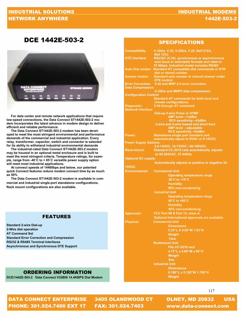
117
117
INDUSTRIAL SOLUTIONS INDUSTRIAL MODEMS NETWORK ANYWHERE 1442E-503-2
DATA CONNECT ENTERPRISE 3405 OLANDWOOD CT OLNEY, MD 20832 USA PHONE: 301.924.7400 EXT 17 FAX: 301.924.7403 www.data-connect.com
DCE 1442E-503-2
For data center and remote network applications that require low-speed connections, the Data Connect ST1442E-503-2 mo-dem incorporates the latest advance in modem design to deliver efficient and reliable performance. The Data Connect ST1442E-503-2 modem has been devel-oped to meet the most stringent environmental and performance demands of the commercial and industrial application. Every relay, transformer, capacitor, switch and connector is selected for its ability to withstand industrial environmental demands The industrial-rated Data Connect ST1442E-503-2 modem may be housed in an optional metal enclosure and is built to meet the most stringent criteria. Temperature ratings, for exam-ple, range from -40˚C to + 85˚C versatile power supply option will meet most industrial applications. At connect speeds of 14400bps and below, our patented quick Connect features reduce modem connect time by as much as 50% The Data Connect ST1442E-503-2 modem is available in com-mercial and industrial single-port standalone configurations. Rack mount configurations are also available.
FEATURES
Standard 2-wire Dial-up 2-Wire dial operation AT Command Set Standard Error Correction and Compression RS232 & RS485 Terminal Interfaces Asynchronous and Synchronous DTE Support
ORDERING INFORMATION DCE/1442E-503-2 Data Connect V32BIS 14.4KBPS Dial Modem
SPECIFICATIONS
Compatibility: V.32bis, V.32, V.22bis, V.22, Bell 212A, Bell 103J. DTE Interface: RS232C (V.24), synchronous or asynchronous auto baud or selectable formats and rates to 57.6kbps. Industrial model includes RS485 Auto Dial modes: Standard AT compatible dial commands or DTR dial or stored number Answer modes: Standard auto answer or manual answer under DTE control Error Correction: V.42 and MNP 2-4 error correction Data Compression: V.42bis and MNP5 data compression Configuration Control: Standard AT commands for both local and remote configurations. Diagnostic: V.54 through AT command Network Interface: Dial-up 2-wire Pulse or DTMF XMT level—12dBm RCV sensitivity—43dBm 2-wire and 4-wire leased and short-haul XMT level – adjustable RCV sensitivity –43dBm Power: Standalone single port standard unit automatically adjust to 9VAC or 9-14VDC Power Supply Options: 5.5-14VDC, 18-75VDC / 66-160VDC Rack-mount: Standard CC-2016 rack automatically adjusts to 85-265VAC, 27-440Hz. Optional DC supply: Automatically adjusts to positive or negative 36-75VDC Environmental: Commercial Unit Operating temperature range 20˚C to +70˚C Humidity 90% non-condensing Industrial Unit Operating temperature range 40˚C to +85˚C Humidity 95% non-condensing Approvals: FCC Part 68 & Part 15, class A Optional International approvals are available. Physical: Commercial Unit Dimensions 5.30”L X 5.05”W 1.53”H Weight 12oz. Rackmount Unit Fits CC-2016 rack 4.73”L x 4.60”W x 80”H Weight 9oz. Industrial Unit Dimensions 6.190”L x 5.120”W 1.750”H Weight

118
118
INDUSTRIAL SOLUTIONS INDUSTRIAL MODEMS NETWORK ANYWHERE MAIN MODEM CHART
DATA CONNECT ENTERPRISE 3405 OLANDWOOD CT OLNEY, MD 20832 USA PHONE: 301.924.7400 EXT 17 FAX: 301.924.7403 www.data-connect.com
MODEL MAX.
SPEED HIGH VOLT.
LOW VOLT. DIAL LEASED
RACK MOUNT
DIN MOUNT
SECUR-ITY
WALL MOUNT PHOTO PAGE
DCE/2400E-000-2 2.4KBPS X 119
DCE/2400E-034-2 2.4KBPS X X 120
DCE/2400E-030-4 2.4KBPS X X X 121
DCE/2400E-330-4 2.4KBPS X X 122
DCE/MIU2.4 2.4KBPS X X X 123
DCE/PPMIU2.4 2.4KBPS X 124
DCE/MD2.4 2.4KBPS X X 125
DCE/PE2.4 2.4KBPS X 127
V.22 MODEM CHECK LIST

119
119
INDUSTRIAL SOLUTIONS INDUSTRIAL MODEMS NETWORK ANYWHERE MAIN MODEM CHART
DATA CONNECT ENTERPRISE 3405 OLANDWOOD CT OLNEY, MD 20832 USA PHONE: 301.924.7400 EXT 17 FAX: 301.924.7403 www.data-connect.com
For data center and remote network applications that require low-speed connections, the Data Connect ST2400E-000-2 modem incorpo-rates the latest advances in modem design to deliver efficient and reli-able performance. The Data Connect ST2400E-000-2 modem has been developed to meet the most stringent environmental and performance demands of the commercial and industrial application. Every relay, transformer, capacitor, switch and connector is selected for its ability to withstand industrial environmental demands. The industrial-rated Data Connect ST2400E-000-2 may be housed in an optional metal enclosure and is built to meet the most stringent cri-teria. Temperature ratings, for example, range from -40˚C to +85˚C ver-satile power supply options will meet most industrial applications. The Data Connect ST2400E-000-2 modem is available in commercial and industrial single-port standalone configurations. Rack mount con-figurations are also available.
FEATURES
Standard 2-wire Dial-up 2-wire and 4-wire leased –line or short haul operation AT Command set Standard Error Correction and Compression RS232 & RS485 Terminal Interfaces Asynchronous and Synchronous DTE Support
SPECIFICATIONS Compatibility: V.22bis, V.22, Bell 212A DTE Interface: RS232C (V.24), synchronous or synchronous— auto baud or selectable formats and rates to 4.8Kbps. Industrial model includes RS485 Auto Dial Modes: Standard AT compatible dial commands or DTR dial or stored number. Answer Modes: Standard auto answer or manual answer under DTE control Error Correction: V.42 and MNP 2-4 error correction Data Compression: V.42bis and MNP5 data compression Configuration Control: Standard AT commands for both local and remote configuration Diagnostic: V.54 through AT command Network Interface: Dial-up 2-wire pulse or DTMF XMT level—adjustable RCV sensitivity—43dBm Power: Standalone single port Standard units automatically adjust to 9VAC or 9-14VAC Power Supply Options: 5.5-14VDC, 18-75VDC 66-160VDC Rack-mount: Standard CC-2016 rack automatically adjusts to 85-265VAC, 27-440Hz. Optional DC supply automatically adjusts to positive or negative 36-75VDC Environmental: Commercial Unit- Operating temperature range -20˚C to +70˚C Humidity—90% non condensing Industrial Unit - Operating temperature range -40˚C to + 85˚C Humidity—95% non condensing Approvals: FCC Part 68 & Part 15, class A. Optional International approvals are available Physical: Commercial Unit: Dimensions 5.30”L x 5.05”W x 1.53”H Weight- 12oz. Rack-mount Unit: Fits CC-2016 rack 4.73”L x 4.60”W x 80”H Weight- 9oz Industrial Unit: Dimensions 6.190”L x 5.12”W x 1.75”H Weight—32oz (metal enclosure)
ORDERING INFORMATION
DCE/2400E-000-2 V.22 2.4KBPS DIAL MODEM
DCE 2400E-000-2

120
120
INDUSTRIAL SOLUTIONS INDUSTRIAL MODEMS NETWORK ANYWHERE MAIN MODEM CHART
DATA CONNECT ENTERPRISE 3405 OLANDWOOD CT OLNEY, MD 20832 USA PHONE: 301.924.7400 EXT 17 FAX: 301.924.7403 www.data-connect.com
DCE 2400E-034-2
For data center and remote network applications that require low-speed connections, the Data Connect ST2400E-034-2 modem incorpo-rates the latest advances in modem design to deliver efficient and reli-able performance. The Data Connect ST2400E-034-2 modem has been developed to meet the most stringent environmental and performance demands of the commercial and industrial application. Every relay, transformer, capacitor, switch and connector is selected for its ability to withstand industrial environmental demands. The industrial-rated Data Connect ST2400E-034-2 may be housed in an optional metal enclosure and is built to meet the most stringent cri-teria. Temperature ratings, for example, range from -40˚C to +85˚C ver-satile power supply options will meet most industrial applications. At connect speeds of 2400bps and below, our patented Quick Con-nect features reduce modem connect time by as much as 50% The Data Connect ST2400E-034-2 modem is available in commercial and industrial single-port standalone configurations. Rack mount con-figurations are also available.
FEATURES
Standard 2-wire Dial-up 2-wire and 4-wire leased –line or short haul operation AT Command set Standard Error Correction and Compression RS232 & RS485 Terminal Interfaces Asynchronous and Synchronous DTE Support Exclusive Quick Connect
ORDERING INFORMATION
DCE/2400E-034-2 2.4KBPS DIAL MODEM
SPECIFICATIONS Compatibility: V.22bis, V.22, Bell 212A DTE Interface: RS232C (V.24), synchronous or synchronous— auto baud or selectable formats and rates to 4.8Kbps. Industrial model includes RS485 Auto Dial Modes: Standard AT compatible dial commands or DTR dial or stored number. Answer Modes: Standard auto answer or manual answer under DTE control Error Correction: V.42 and MNP 2-4 error correction Data Compression: V.42bis and MNP5 data compression Configuration Control: Standard AT commands for both local and remote configuration Diagnostic: V.54 through AT command Network Interface: Dial-up 2-wire pulse or DTMF XMT level—adjustable RCV sensitivity—43dBm Power: Standalone single port Standard units automatically adjust to 9VAC or 9-14VAC Power Supply Options: 5.5-14VDC, 18-75VDC 66-160VDC Rack-mount: Standard CC-2016 rack automatically adjusts to 85-265VAC, 27-440Hz. Optional DC supply automatically adjusts to positive or negative 36-75VDC Environmental: Commercial Unit- Operating temperature range -20˚C to +70˚C Humidity—90% non condensing Industrial Unit - Operating temperature range -40˚C to + 85˚C Humidity—95% non condensing Approvals: FCC Part 68 & Part 15, class A. Optional International approvals are available Physical: Commercial Unit: Dimensions 5.30”L x 5.05”W x 1.53”H Weight- 12oz. Rack-mount Unit: Fits CC-2016 rack 4.73”L x 4.60”W x 80”H Weight- 9oz Industrial Unit: Dimensions 6.190”L x 5.12”W x 1.75”H Weight—32oz (metal enclosure)

121
121
INDUSTRIAL SOLUTIONS INDUSTRIAL MODEMS NETWORK ANYWHERE MAIN MODEM CHART
DATA CONNECT ENTERPRISE 3405 OLANDWOOD CT OLNEY, MD 20832 USA PHONE: 301.924.7400 EXT 17 FAX: 301.924.7403 www.data-connect.com
DCE 2400E--030-4
SPECIFICATIONS Compatibility: V.22bis, V.22, Bell 212A DTE Interface: RS232C (V.24), synchronous or synchronous— auto baud or selectable formats and rates to 4.8Kbps. Industrial model includes RS485 Auto Dial Modes: Standard AT compatible dial commands or DTR dial or stored number. Answer Modes: Standard auto answer or manual answer under DTE control Error Correction: V.42 and MNP 2-4 error correction Data Compression: V.42bis and MNP5 data compression Configuration Control: Standard AT commands for both local and remote configuration Diagnostic: V.54 through AT command Network Interface: Dial-up 2-wire pulse or DTMF XMT level—adjustable RCV sensitivity—43dBm Power: Standalone single port Standard units automatically adjust to 9VAC or 9-14VAC Power Supply Options: 5.5-14VDC, 18-75VDC 66-160VDC Rack-mount: Standard CC-2016 rack automatically adjusts to 85-265VAC, 27-440Hz. Optional DC supply automatically adjusts to positive or negative 36-75VDC Environmental: Commercial Unit- Operating temperature range -20˚C to +70˚C Humidity—90% non condensing Industrial Unit - Operating temperature range -40˚C to + 85˚C Humidity—95% non condensing Approvals: FCC Part 68 & Part 15, class A. Optional International approvals are available Physical: Commercial Unit: Dimensions 5.30”L x 5.05”W x 1.53”H Weight- 12oz. Rack-mount Unit: Fits CC-2016 rack 4.73”L x 4.60”W x 80”H Weight- 9oz Industrial Unit: Dimensions 6.190”L x 5.12”W x 1.75”H Weight—32oz (metal enclosure)
For data center and remote network applications that require low-speed connections, the Data Connect ST2400E-030-4 modem incorpo-rates the latest advances in modem design to deliver efficient and reli-able performance. The Data Connect ST2400E-O30-4 modem has been developed to meet the most stringent environmental and performance demands of the commercial and industrial application. Every relay, transformer, capacitor, switch and connector is selected for its ability to withstand industrial environmental demands. The industrial-rated Data Connect ST2400E-030-4 may be housed in an optional metal enclosure and is built to meet the most stringent cri-teria. Temperature ratings, for example, range from -40˚C to +85˚C ver-satile power supply options will meet most industrial applications. At connect speeds of 2400bps and below, our patented Quick Con-nect features reduce modem connect time by as much as 50% The Data Connect ST2400E-030-4 modem is available in commercial and industrial single-port standalone configurations. Rack mount con-figurations are also available.
FEATURES
Standard 2-wire Dial-up 2-wire and 4-wire leased –line or short haul operation AT Command set Standard Error Correction and Compression RS232 & RS485 Terminal Interfaces Asynchronous and Synchronous DTE Support Exclusive Quick Connect
ORDERING INFORMATION
DCE/2400E-030-4 2.4KBPS DIAL & LEASED LINE MODEM

122
122
INDUSTRIAL SOLUTIONS INDUSTRIAL MODEMS NETWORK ANYWHERE MAIN MODEM CHART
DATA CONNECT ENTERPRISE 3405 OLANDWOOD CT OLNEY, MD 20832 USA PHONE: 301.924.7400 EXT 17 FAX: 301.924.7403 www.data-connect.com
DCE 2400E-330-4
For data center and remote network applications that require low-speed connections, the Data Connect ST2400E modem series incorpo-rates the latest advances in modem design to deliver efficient and reli-able performance. The Data Connect ST2400E series modem has been developed to meet the most stringent environmental and performance demands of the commercial and industrial application. Every relay, transformer, capacitor, switch and connector is selected for its ability to withstand industrial environmental demands. The industrial-rated Data Connect ST2400E may be housed in an optional metal enclosure and is built to meet the most stringent criteria. Temperature ratings, for example, range from -40˚C to +85˚C versatile power supply options will meet most industrial applications. At connect speeds of 2400bps and below, our patented Quick Con-nect features reduce modem connect time by as much as 50% The Data Connect ST2400E series modem is available in commercial and industrial single-port standalone configurations. Rack mount con-figurations are also available.
FEATURES
Standard 2-wire Dial-up 2-wire and 4-wire leased –line or short haul operation AT Command set Standard Error Correction and Compression RS232 & RS485 Terminal Interfaces Asynchronous and Synchronous DTE Support Exclusive Quick Connect
ORDERING INFORMATION
DCE/2400E-000-2 2.4KBPS DIAL MODEM
SPECIFICATIONS Compatibility: V.22bis, V.22, Bell 212A DTE Interface: RS232C (V.24), synchronous or synchronous— auto baud or selectable formats and rates to 4.8Kbps. Industrial model includes RS485 Auto Dial Modes: Standard AT compatible dial commands or DTR dial or stored number. Answer Modes: Standard auto answer or manual answer under DTE control Error Correction: V.42 and MNP 2-4 error correction Data Compression: V.42bis and MNP5 data compression Configuration Control: Standard AT commands for both local and remote configuration Diagnostic: V.54 through AT command Network Interface: Dial-up 2-wire pulse or DTMF XMT level—adjustable RCV sensitivity—43dBm Power: Standalone single port Standard units automatically adjust to 9VAC or 9-14VAC Power Supply Options: 5.5-14VDC, 18-75VDC 66-160VDC Rack-mount: Standard CC-2016 rack automatically adjusts to 85-265VAC, 27-440Hz. Optional DC supply automatically adjusts to positive or negative 36-75VDC Environmental: Commercial Unit- Operating temperature range -20˚C to +70˚C Humidity—90% non condensing Industrial Unit - Operating temperature range -40˚C to + 85˚C Humidity—95% non condensing Approvals: FCC Part 68 & Part 15, class A. Optional International approvals are available Physical: Commercial Unit: Dimensions 5.30”L x 5.05”W x 1.53”H Weight- 12oz. Rack-mount Unit: Fits CC-2016 rack 4.73”L x 4.60”W x 80”H Weight- 9oz Industrial Unit: Dimensions 6.190”L x 5.12”W x 1.75”H Weight—32oz (metal enclosure)

123
123
INDUSTRIAL SOLUTIONS INDUSTRIAL MODEMS NETWORK ANYWHERE MAIN MODEM CHART
DATA CONNECT ENTERPRISE 3405 OLANDWOOD CT OLNEY, MD 20832 USA PHONE: 301.924.7400 EXT 17 FAX: 301.924.7403 www.data-connect.com
To service the growing need for efficient, reliable data communica-tion in a harsh environmental of utility substations and industrial facili-ties, has developed a 28800bps modem that can operate from various AC/DC power supplies and survive high surge levels and extreme heat and cold. All this without compromising the performance expected from state-of-the-art communications devices. With the rapid move toward “intelligent” substation, where meters relays, RTU’s, SCADA system, etc are able to “talk” to a remote opera-tor, communication devices such as modems moving off the desktop and into the field, where the convenience of 115VAC power outlets and climate control are usually hard to find. Data Connect Enterprise has addressed this problem by developing the MIU28.8 series modem designed specifically for harsh environ-ments. The MIU2.4 series modem is highly sophisticated full duplex, V.22 data modem that designed to interface with RS232, RS485 (external device), 5V logic (TTL) or simple send and receive signals The MIU2.4 series modem operates on a dial-up system. The MIU2.4 series modem is powered from unique power supply that enables it to operate on any AC or DC voltage ranging from 48V to 240V. A low voltage version (9-36VDC) is also available. The MIU28.8 modem is designed to work in temperatures from 40˚C to 85˚C and is surge protected on both the power and analog lines. The MIU2.4 series modem is bundled in a 5-3/8” x 1-3/8” non-metallic enclosure, suitable for desktop or wall mounting. Also see our Data sheets on the MIU/power-port low voltage mo-dems, the “Myriad” Rack Mount Modem, MIU (Bell), MIU14.4 and MIU9.6FPD modems
FEATURES Modem Interface Units AC/DC Powered Substation Hardened Communication Interface Units 2.4kbps 2-wire Dial Modem 48 to 220 AC/DC Power Supply IEC801-4 Surge Protection -40˚C to +85˚C Operating Temperature For Meters, Relay, SCADA etc.
SPECIFICATIONS Modem Line Speeds: Asynchronous 2400, 1200, 300bps DTE Rates: Above modem line speeds (IE; with data compression) 9600bps Standards: V.22, Bell 212A, and Bell 103 Transmission Line: Dial Compatibility: Hayes Extended AT command set Power Supply: 48VAC/DC to 220VAC/DC (Optional 9-36VDC) Power Connector: 4-ft AC Cord with 3-pin screw terminal connector included Case size: 5-3/8” x 4” x 1-3/8” Digital Port: RS232 withDB9 connector Analog Port: RJ11 Modular Jack Surge Protection: (power line) 8kV [exceeds IEC801-4] (20kV IE801-5 available if required) Surge Protection: 3.75VAC Environment: -40˚C to +85˚C, 0 to 95% humidity (non-condensing) Certifications: FCC Part 68, Industry Canada
ORDERING INFORMATION DCE/MIU-2.4 V.22 2.4Kbps2-Wire Dial Modem DCE/MIU-2.4-LV V.22 2.4Kbps2-Wire Dial Modem Low Voltage
DCE MIU2.4

124
124
INDUSTRIAL SOLUTIONS INDUSTRIAL MODEMS NETWORK ANYWHERE MAIN MODEM CHART
DATA CONNECT ENTERPRISE 3405 OLANDWOOD CT OLNEY, MD 20832 USA PHONE: 301.924.7400 EXT 17 FAX: 301.924.7403 www.data-connect.com
SPECIFICATIONS Modem Line Speeds: Asynchronous 2400, 1200, 300bps DTE Rates: Above modem line speeds (IE; with data compression) 9600bps Standards: V.22, Bell 212A, and Bell 103 Transmission Line: Dial Compatibility: Hayes Extended AT command set Powered through the RS232 (DB25) data interface port or external jack (optional 7-16VDC available) Case size: 5-3/8” x 4” x 1-3/8” Digital Port: RS232 withDB9 connector Analog Port: RJ11 Modular Jack Surge Protection: (power line) 8kV [exceeds IEC801-4] (20kV IE801-5 available if required) Surge Protection: 3.75VAC Environment: -40˚C to +85˚C, 0 to 95% humidity (non-condensing)
Certifications: FCC Part 68, Industry Canada
ORDERING INFORMATION DCE/MIU-PP2.4 V.22 2.4Kbps2-Wire Dial Modem with 5VDC Power thru DB25
To service the growing need for efficient, reliable data communi-cation in a harsh environmental of utility substations and industrial facilities, has developed a 2400bps modem that can operate from various AC/DC power supplies and survive high surge levels and extreme heat and cold. All this without compromising the perform-ance expected from state-of-the-art communications devices. With the rapid move toward “intelligent” substation, where meters relays, RTU’s, SCADA system, etc are able to “talk” to a remote op-erator, communication devices such as modems moving off the desktop and into the field, where the convenience of 115VAC power outlets and climate control are usually hard to find. Data Connect Enterprise has addressed this problem by develop-ing the PowerPort-MIU2.4 series modem designed specifically for harsh environments. The PowerPort-MIU2.4 series modem is highly sophisticated full duplex, V.22 data modem that designed to interface with RS232, RS485 (external device), 5V logic (TTL) or simple send and receive signals The PowerPortMiu2.4 series modem operates on a dial-up system. The PowerPort-MIU2.4 series modem is powered from unique power supply that enables it to operate on any AC or DC voltage ranging from 48V to 240V. A low voltage version (9-36VDC) is also available. The PowerPortMIU2.4 modem is designed to work in tem-peratures from 40˚C to 85˚C and is surge protected on both the power and analog lines. The PowerPort-MIU2.4 series modem is bundled in a 5-3/8” x 1-3/8” non-metallic enclosure, suitable for desktop or wall mounting. Also see our Data sheets on the MIU/power-port low voltage mo-dems, the “Myriad” Rack Mount Modem, MIU202T (Bell), MIU9.6FPD, MIU14.4, and MIU28.8 modems.
DCE MIU-PP2.4
FEATURES Modem Interface Units AC/DC Powered Substation Hardened Communication Interface Units 2.4kbps 2-wire Dial Modem Powered through the RS232 (DB25) data interface port or External Jack (Optional 7-16VDC available) Automatic “Power Down” when inactive IEC801-4 Surge Protection -40˚C to +85˚C Operating Temperature Hayes AT compatible

125
125
INDUSTRIAL SOLUTIONS INDUSTRIAL MODEMS NETWORK ANYWHERE MAIN MODEM CHART
DATA CONNECT ENTERPRISE 3405 OLANDWOOD CT OLNEY, MD 20832 USA PHONE: 301.924.7400 EXT 17 FAX: 301.924.7403 www.data-connect.com
FEATURES 2.4kbps 2-wire Dial Line Modem IEC801-4 Surge Protection -20˚C to +85˚C Operating Temperature For Meters, Relays, SCADA, etc.
MD2.4 SPECIFICATIONS Modem Line Speeds Asynchronous 2400, 1200, 300bps DTE Rate Above modem line speeds (IE; with data compression 9.6kbps Standards V.22, Bell 212A, Bell 103 Transmission Line 2-wire dial Compatibility Hayes Extended AT Command Set Digital Port RS232 with DB9 Connector Analog Port RJ11Modular Jack Surge Protection (Power Line) 8kV [Exceeds IEC801-4] (20kV IE801-5 (available if required) Surge Protection 3.75VAC Environment -40˚C to + 85˚C, 0 to 95% humidity (non-condensing) Certifications FCC Part 68, Industry Canada
The Data Connect MD2.4 is the Rack-mount version of the Data Connect MIU2.4. The same functionally that can be found in the MIU28.8 can be found in the MD14.4L. The Data Connect MD2.4is a Bell V.22 modem designed for asynchronous operation at 0 to 2400bps over voice grade lines. The modem is intended for use on 2-wire or 4-wire leased lines. The MD2.4 is comprised of MDMC carrier card and PE14.4 mod-ule. Up to 18 MD28.8 can be front loaded into MDR Modem Bank. The MDR Modem Bank is an industrial grade 19” X 3U rack mountable chassis. MDR Modem Bank is powered from a wide range of AC and DC voltages. Two power supply cards can be installed to provide automatic back up in the event the primary power supply fails. The MDR will operate in temperatures from -20˚C to + 85˚C and is surge protected on both power analog lines. Two power supply slots are provided. Power supply cards are available for any voltage in the range 9-150VDC and 9-275VAC. A single power supply card will power all 18 MD28.8. In additional to the MD28.8 the MDR Modem Bank also houses the MD14.4L, MD14.4, MD9.6FPD, and MD202T.
DCE MD2.4
ORDERING INFORMATION DCE/MD2.4 V.22 2.4Kbps2-Wire Dial Rackmount Modem

126
126
INDUSTRIAL SOLUTIONS INDUSTRIAL MODEMS NETWORK ANYWHERE MAIN MODEM CHART
DATA CONNECT ENTERPRISE 3405 OLANDWOOD CT OLNEY, MD 20832 USA PHONE: 301.924.7400 EXT 17 FAX: 301.924.7403 www.data-connect.com
DCE MDR
The Data Connect MDR Modem Chassis is designed to house eighteen (18) DCE MD Modem Cards and two (2) DCE MDP Power Supplies. The DCE MDR Modem Chassis is hardened industrial grade, 19” wide, 3U height (5.25”H), and constructed heavy gauge steel with plating for corrosion resistance. The DCE MD Modem Cards are comprised of a DCE MDMC Modem Carrier Card and a DCE PE OEM Card. The DCE MD202T (Bell 202T), MD9.6FPD (Proprietary), MD2.4 (V.22), MD14.4 (V.32bis), MD14.4L (V.32bis), and MD28.8 (V.34) operate within the DCE MDR Modem Chassis and are hot-swappable. Any mix of the DCE MD modems can be utilized simultaneously. Two (2) DCE MDP Power Supplies Cards provide full redundancy and are available for any voltage in the range of 9-150VDC and 9-275VAC. A single DCE MDP Power Supply Card powers eighteen (18) Modem Cards. A second DCE MDP Power Supply Card, if in-stalled, provides automatic backup in the event of a failure of the primary DCE MDP Power Supply Card.
FEATURES
18 Modem Slots Dial & Leased Line Modems V.22, 202T, 9.6FPD, V.32bis, V.34 Hayes AT Compatibility Full Array of LEDs Standard 19” x 5.25” (3U) Euro-Chassis AC or DC Power from 9 to 300VAC or VDC Dual Power Supplies with Full Redundancy Ideal for SCADA Master Stations
SPECIFICATIONS EIA Standards Compliant with EIA Standard EIA-310-C Modem Interface Connectors (Rear) Serial RS232: DB25F Analog Port: RJ11 LEDs (Front) (Top to bottom) DTR: Data Terminal Ready TXD: Transmit Data RXD: Receive Data MR: Modem Ready CD: Carrier Detect RTS: Request to Send CTS: Clear to Send RI: Ring Indicator Power Requirements AC Power: 9 to275VAC – Fused Socket (IEC 320) DC Power: 9 to 150VDC – Screw Terminals – 9 to 150VDC Dimensions Width: 19” Depth: Height: 5.25” (3U) Environmental Operating Temperature: -20 to +85 Degrees Celsius

127
127
INDUSTRIAL SOLUTIONS INDUSTRIAL MODEMS NETWORK ANYWHERE MAIN MODEM CHART
DATA CONNECT ENTERPRISE 3405 OLANDWOOD CT OLNEY, MD 20832 USA PHONE: 301.924.7400 EXT 17 FAX: 301.924.7403 www.data-connect.com
SPECIFICATIONS
PE2.4 Modem Line Speeds: Asynchronous 2400, 1200, 300bps Standards: V.22bis, V.22, Bell212A, Bell 103 Transmission Line: Dial-up Compatibility: Hayes Extended AT Command Set Power: 5V logic (TTL)
To service the growing need for efficient, reliable data communica-tion in harsh environments of utility substations and industrial facili-ties, DCE has developed a series of OEM PCB modems that can oper-ate at 5V logic (TTL) or simple send and receive signals and survive high surge levels and extreme heat and cold. All this without compro-mising the performance expected from state-of-the-art communication devices. With the rapid move toward “intelligent” substations, where meters, relays, RTUs, SCADA systems, etc. are able to “talk” to a re-mote operator, communication devices such as modems are moving off the desktop and into the meters, RTUs, and SCADA units where the conveniences of a standalone modem is unacceptable. Data Connect Enterprise has addressed this problem by developing the PE2.4, 9.6FPD, 14.4, 14.4L, 202T, and 28.8 OEM modems designed specifically for harsh environments. The PE OEM modems are highly sophisticated full duplex, V.22bis data modems that are designed to interface with RS232, RS485 (external device), 5V logic (TTL) or simple send and receive signals. The PE2.4, 14.4, and 28.8 OEM modems operate at full or half duplex on a dial up line. The PE202T, 14.4L, and 9.6FPD OPM modems operate full or half duplex on 2 or 4 wire leased lines. The PE OEM PECs can be found in the MIU modems, MD modem cards, and the MIU Power Port modems.
FEATURES
Modem Interface Units 5V logic (TTL) Simple send and receive signals 2400kbps 2-wire dial-up line modem 5V logic (TTL) power supply IEC801-4 surge protection -40°C to +85°C operating temperature
DCE PE2.4
ORDERING INFORMATION
DCE/PE2.4 2-wire dial-up PCB

128
128
INDUSTRIAL SOLUTIONS INDUSTRIAL MODEMS NETWORK ANYWHERE V.23 & BELL 202 MODEM CHECK LIST
DATA CONNECT ENTERPRISE 3405 OLANDWOOD CT OLNEY, MD 20832 USA PHONE: 301.924.7400 EXT 17 FAX: 301.924.7403 www.data-connect.com
V.23 & BELL 202 MODEM CHECK LIST
MODEL MAX.
SPEED HIGH VOLT.
LOW VOLT. DIAL LEASED
RACK MOUNT
DIN MOUNT
SECUR-ITY
WALL MOUNT PHOTO PAGE
DCE/IGV23 75BPS X X X X X X 129
DCE/IG202T 0-1200BPS X X X X X X 130
DCE/IG202T-R38 0-1200BPS X X X 131
DCE/MIU/202T 0-1200BPS X X X 132
DCE/MD202T 0-1200BPS X X 133
DCE/PE202T 0-1200BPS X 135
DCE/202TE-037-4 1200BPS X 136
DCE/202TR-037-4 1200BPS X 137

129
129
INDUSTRIAL SOLUTIONS INDUSTRIAL MODEMS NETWORK ANYWHERE IGV.23
DATA CONNECT ENTERPRISE 3405 OLANDWOOD CT OLNEY, MD 20832 USA PHONE: 301.924.7400 EXT 17 FAX: 301.924.7403 www.data-connect.com
The Data Connect low speed IGV.23 Industrial Grade V.23 modem is designed and manufactured for rugged industrial communication networks. The IGV.23 delivers cost effective and reliable 1200bps asynchronous solutions for point to point and multipoint connec-tivity. The IGV.23 Industrial Grade V.23 modem is ideal for industrial communication application including SCADA systems, RTUs, traffic monitor and control, and industrial and automation networks. The V.23 supports RTUs with switch selectable settings and no AT com-mand set required. The IGV.23 modem is designed to operate over 4-wire full duplex or 2-wire half duplex over unconditioned leased lines or private metallic circuits. For optimum performance, the modem employs FSK modulation to be compatible with V.23 standards, which can communicate over a variety of transmission lines. The IGV.23 Industrial Grade V.23 modem can operate over a wide range of AC or DC power supply voltages and temperatures. With Proven reliability and ease of installation the V.23 is ideal for point-to-point and point-to-multipoint polling networks, where reliability and low-network latency are critical for system performance. With its Auto-RTS mode, the modem can support DTE/RTUs with 3-wire serial interface (TD, RD, and SG) in point-to-point and multi-point polling applications. The IGV.23 industrial grade V.23 modem has selectable EIA RS-232/V.24 and RS-485 DTE support. It also features built-in diagnos-tics for local and remote testing. The configuring and options on the IG202T is provided by DIP switches and jumpers, eliminating the need for an AT command set. The IGV.23 has heavy-duty surge pro-tection at the power supply and leased line inputs. IGV.23 also uses an isolated DC to DC power converter for protecting critical DC or battery power systems.
ORDERING INFORMATION
DCE/IGV.23 STANDALONE (100-240 VAC) DCE/IGV.23-DC STANDALONE (10-48 VDC) DCE/IGV.23-HV STANDALONE (100-240 VAC, 85-400 VDC) DCE/IGV.23-RM RM16M RACKMOUNT MODULE DCE/IGV.23-WMB WALL-MOUNT/PANEL-MODULE DCE/IGV.23-DIN DIN-MOUNT KIT
SPECIFICATIONS DATA RATE SUPPORT: Data Speed 0-1200 bps in V.23 mode Data Format Asynchronous, transparent character format (10 or 11-bit character with 1 or 2 stop bits) MODULATION: Frequency Shift Key (FSK) V.23 Mode: Mark 1300 Hz Space 2100 Hz Soft Carrier 900 Hz TRANSMISSION LINE INTERFACE: Leased Line TELCO voice band 2 or 4 –wire leased lines Private or metallic circuits 2 or 4 –wire, 19-26 AWG Connector: 4 PIN RJ-11C modular jack Transmitter output level: 0 to -12dbm, selectable DTE/RTU Interface: The modem provides serial ports to support either the RS-485 Inter-face standards RS-232 INTERFACE: Connector: D9-F Signals: RTS, CTS, CD, TD, RD, DSR, and SG RS-485 INTERFACE: Connector: RJ-11CSignals: 4-wire full-duplex TX+, TX-, RX+, RX- FRONT PANEL INDICATORS & CONTROL S: RTS, CTS, TD, CD, RD, MR, ALB, DLB TEST Switch: Push Button for Analog Loopback, Digital Loopback AC & DC POWER SUPPORT: Standalone: 10-48 VDC: 85-400 VDC, 100-240 VAC Rack mount module: plug-in RM16M modem rack POWER + CURRENT CONSUMPTION: 75 Ma @ 12 VDC 18 Ma @ 48VDC MECHANICAL: Enclosure dimensions: 4.1” (W) x 4.9” (L) x1.4” (H) 104mm (W) x 125mm (L) x36mm (H) weight: 0.51lbs, without AC power module ENVIRONMENT: Operation: -40 Degrees Celsius to + 85 Degrees Celsius Storage: -40 Degrees Celsius to + 85 Degrees Celsius
DCE IGV.23

130
130
INDUSTRIAL SOLUTIONS INDUSTRIAL MODEMS NETWORK ANYWHERE IG202T
DATA CONNECT ENTERPRISE 3405 OLANDWOOD CT OLNEY, MD 20832 USA PHONE: 301.924.7400 EXT 17 FAX: 301.924.7403 www.data-connect.com
The Data Connect low speed IG202T Industrial Grade Bell 202 modem is designed and manufactured for rugged industrial com-munication networks. The IG202T delivers cost effective and reli-able 1200bps asynchronous solutions for point to point and multi-point connectivity. The IG202T Industrial Grade Bell 202 modem is ideal for indus-trial communication application including SCADA systems, RTUs, traffic monitor and control, and industrial and automation networks. The IG202T supports RTUs with switch selectable settings and no AT command set required. The IG202T modem is designed to oper-ate over 4-wire full duplex or 2-wire half duplex over unconditioned leased lines or private metallic circuits. For optimum performance, the modem employs FSK modulation to be compatible with Bell 202 standards, which can communicate over a variety of transmission lines. The IG202T Industrial Grade Bell 202 modem can operate over a wide range of AC or DC power supply voltages and temperatures. With Proven reliability and ease of installation the IG202T is ideal for point-to-point and point-to-multipoint polling networks, where reliability and low-network latency are critical for system perform-ance. With its Auto-RTS mode, the modem can support DTE/RTUs with 3-wire serial interface (TD, RD, and SG) in point-to-point and multi-point polling applications. The IG202T industrial grade Bell 202 modem has selectable EIA RS-232/V.24 and RS-485 DTE support. It also features built-in diag-nostics for local and remote testing. The configuring and options on the IG202T is provided by DIP switches and jumpers, eliminating the need for an AT command set. The IG202T has heavy-duty surge protection at the power supply and leased line inputs. IG202T also uses an isolated DC to DC power converter for protecting critical DC or battery power systems.
SPECIFICATIONS DATA RATE SUPPORT: Data Speed 0-1200 bps in Bell 202T mode Data Format Asynchro-nous, transparent character format (10 or 11-bit character with 1 or 2 stop bits) MODULATION: Frequency Shift Key (FSK) Bell 202 Mode: Mark 1200 Hz Space 2200 Hz Softt Carrier 900 Hz TRANSMISSION LINE INTERFACE: Leased Line TELCO voice band 2 or 4 –wire leased lines Private or metallic circuits 2 or 4 –wire, 19-26 AWG Connector: 4 PIN RJ-11C modular jack Transmitter output level: 0 to -12dbm, selectable DTE/RTU Interface: The modem provides serial ports to support either the RS-485 Interface standards RS-232 INTERFACE: Connector: D9-F Signals: RTS, CTS, CD, TD, RD, DSR, and SG RS-485 INTERFACE: Connector: RJ-11CSignals: 4-wire full-duplex TX+, TX-, RX+, RX- FRONT PANEL INDICATORS & CONTROL S: RTS, CTS, TD, CD, RD, MR, ALB, DLB TEST Switch: Push Button for Analog Loopback, Digital Loopback AC & DC POWER SUPPORT: Standalone: 10-48 VDC: 85-400 VDC, 100-240 VAC Rack mount module: plug-in RM16M modem rack POWER + CURRENT CONSUMPTION: 75 Ma @ 12 VDC 18 Ma @ 48VDC MECHANICAL: Enclosure dimensions: 4.1” (W) x 4.9” (L) x1.4” (H) 104mm (W) x 125mm (L) x36mm (H) weight: 0.51lbs, without AC power module ENVIRONMENT: Operation: -40 Degrees Celsius to + 85 Degrees Celsius Storage: -40 Degrees Celsius to + 85 Degrees Celsius Humidity: up to 95% non-condensing
ORDERING INFORMATION
DCE/IG202T STANDALONE (100-240 VAC) DCE/IG202T-DC STANDALONE (10-48 VDC) DCE/IG202T-HV STANDALONE (100-240 VAC, 85-400 VDC) DCE/IG202T-RM RM16M RACKMOUNT MODULE DCE/IG202T-WMB WALL-MOUNT/PANEL-MODULE DCE/IG202T-DIN DIN-MOUNT KIT
DCE IG202T
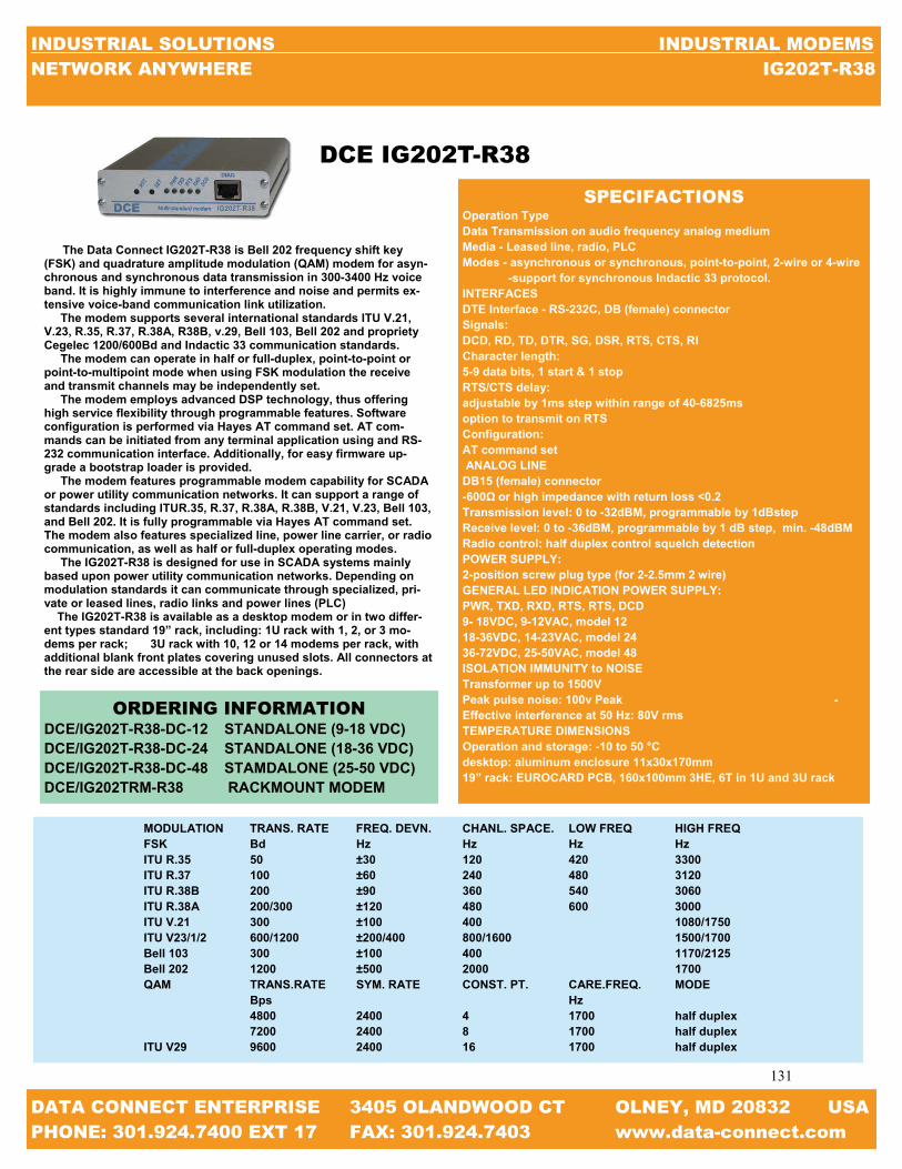
131
131
INDUSTRIAL SOLUTIONS INDUSTRIAL MODEMS NETWORK ANYWHERE IG202T-R38
DATA CONNECT ENTERPRISE 3405 OLANDWOOD CT OLNEY, MD 20832 USA PHONE: 301.924.7400 EXT 17 FAX: 301.924.7403 www.data-connect.com
The Data Connect IG202T-R38 is Bell 202 frequency shift key (FSK) and quadrature amplitude modulation (QAM) modem for asyn-chronous and synchronous data transmission in 300-3400 Hz voice band. It is highly immune to interference and noise and permits ex-tensive voice-band communication link utilization. The modem supports several international standards ITU V.21, V.23, R.35, R.37, R.38A, R38B, v.29, Bell 103, Bell 202 and propriety Cegelec 1200/600Bd and Indactic 33 communication standards. The modem can operate in half or full-duplex, point-to-point or point-to-multipoint mode when using FSK modulation the receive and transmit channels may be independently set. The modem employs advanced DSP technology, thus offering high service flexibility through programmable features. Software configuration is performed via Hayes AT command set. AT com-mands can be initiated from any terminal application using and RS-232 communication interface. Additionally, for easy firmware up-grade a bootstrap loader is provided. The modem features programmable modem capability for SCADA or power utility communication networks. It can support a range of standards including ITUR.35, R.37, R.38A, R.38B, V.21, V.23, Bell 103, and Bell 202. It is fully programmable via Hayes AT command set. The modem also features specialized line, power line carrier, or radio communication, as well as half or full-duplex operating modes. The IG202T-R38 is designed for use in SCADA systems mainly based upon power utility communication networks. Depending on modulation standards it can communicate through specialized, pri-vate or leased lines, radio links and power lines (PLC) The IG202T-R38 is available as a desktop modem or in two differ-ent types standard 19” rack, including: 1U rack with 1, 2, or 3 mo-dems per rack; 3U rack with 10, 12 or 14 modems per rack, with additional blank front plates covering unused slots. All connectors at the rear side are accessible at the back openings.
SPECIFACTIONS Operation Type Data Transmission on audio frequency analog medium Media - Leased line, radio, PLC Modes - asynchronous or synchronous, point-to-point, 2-wire or 4-wire -support for synchronous Indactic 33 protocol. INTERFACES DTE Interface - RS-232C, DB (female) connector Signals: DCD, RD, TD, DTR, SG, DSR, RTS, CTS, RI Character length: 5-9 data bits, 1 start & 1 stop RTS/CTS delay: adjustable by 1ms step within range of 40-6825ms option to transmit on RTS Configuration: AT command set ANALOG LINE DB15 (female) connector -600Ω or high impedance with return loss <0.2 Transmission level: 0 to -32dBM, programmable by 1dBstep Receive level: 0 to -36dBM, programmable by 1 dB step, min. -48dBM Radio control: half duplex control squelch detection POWER SUPPLY: 2-position screw plug type (for 2-2.5mm 2 wire) GENERAL LED INDICATION POWER SUPPLY: PWR, TXD, RXD, RTS, RTS, DCD 9- 18VDC, 9-12VAC, model 12 18-36VDC, 14-23VAC, model 24 36-72VDC, 25-50VAC, model 48 ISOLATION IMMUNITY to NOISE Transformer up to 1500V Peak pulse noise: 100v Peak -Effective interference at 50 Hz: 80V rms TEMPERATURE DIMENSIONS Operation and storage: -10 to 50 °C desktop: aluminum enclosure 11x30x170mm 19” rack: EUROCARD PCB, 160x100mm 3HE, 6T in 1U and 3U rack
MODULATION TRANS. RATE FREQ. DEVN. CHANL. SPACE. LOW FREQ HIGH FREQ FSK Bd Hz Hz Hz Hz ITU R.35 50 ±30 120 420 3300 ITU R.37 100 ±60 240 480 3120 ITU R.38B 200 ±90 360 540 3060 ITU R.38A 200/300 ±120 480 600 3000 ITU V.21 300 ±100 400 1080/1750 ITU V23/1/2 600/1200 ±200/400 800/1600 1500/1700 Bell 103 300 ±100 400 1170/2125 Bell 202 1200 ±500 2000 1700 QAM TRANS.RATE SYM. RATE CONST. PT. CARE.FREQ. MODE Bps Hz 4800 2400 4 1700 half duplex 7200 2400 8 1700 half duplex ITU V29 9600 2400 16 1700 half duplex
ORDERING INFORMATION DCE/IG202T-R38-DC-12 STANDALONE (9-18 VDC) DCE/IG202T-R38-DC-24 STANDALONE (18-36 VDC) DCE/IG202T-R38-DC-48 STAMDALONE (25-50 VDC) DCE/IG202TRM-R38 RACKMOUNT MODEM
DCE IG202T-R38

132
132
INDUSTRIAL SOLUTIONS INDUSTRIAL MODEMS NETWORK ANYWHERE MIU-202T
DATA CONNECT ENTERPRISE 3405 OLANDWOOD CT OLNEY, MD 20832 USA PHONE: 301.924.7400 EXT 17 FAX: 301.924.7403 www.data-connect.com
Bell 202T continues to be the standard of choices in many utility and industrial multi-drop data communications applications. The Data Connect Enterprise MIU202T can be powered from a wide range of DC and AC voltages, is surge protected on both the power and analog lines, and will operate in extreme heat and cold. Ideal for multi-drop applications over leased lines and private lines. The MIU202T is a Bell Standard 202T modem designed for asyn-chronous operation at 0 to 1200 bps over voice grade lines and pilot wires. The modem is intended for use on leased lines and private lines and provides half-duplex communications on 2-wire lines, or full-duplex on 4-wire. Most modem manufactures have abandoned the Bell 202T in favor of the much higher speed modulation preferred in dial-up systems. However, Bell 202T remains the standard of choice in many utility and industrial applications where relatively small amounts of data are to be transmitted in multi-point networks. To meet this continued demand, Data Connect Enterprise has added the MIU202T to its range of Communications Interface Units (see separate brochure). The MIU202T can be powered from any AC or DC voltage in the range of 48V to 220V.A 9-36VDC version is also available. It is de-signed to work extended temperatures ranging from -40C to +80C, and its surge protected to 8kV, double the voltage requirements of IEC801-4 standard. All of this is bundled in a 5-3/8“x 4” x 1-3/8,’ non metallic enclo-sure, suitable for desktop or wall mounting. Rack mount cards are also available for Data Connect Enterprise “Myriad” system (see separate brochure)
SPECIFICATIONS
Data Rate: Asynchronous 0-1200bps over voice grade leased or pilot lines Modulation: Bell 202T Operation: phase coherent, (FSK) Full duplex over 4-wire leased or private lines Half duplex over 2-wire leased or private lines (constant or switched carrier, Dip Switch selectable) Power supply: 48VAC/DC (Optional 9- 36VDC) Power consumption: 15mA @ 48VD; 7.5mA @ 115CDV; 7.5mA @ 125VDC Digital Port: RS232 with DB9 Connector Analog Port: RJ11 Power connector: 3-pin with screw terminals for customer supplied cable Case Size: 5-3/8” x 4” x 1-3/8” Surge protection: (Power Line) - 8kV [Exceeds IEC801-4] Surge protection: (Analog Line) - 3.75kVac Operation equipment -40C to +85C, 0 to 95% humidity (non-condensing)
Carrier Frequencies: Bell 202T… Mark: 1200Hz ± 0.1% Space: 2200Hz ± 0.1%
FEATURES
0-1200 bps, leased AC/DC powered substation hardened Bell 202T 0-1200 bps over voice grade leased lines Point-to-point or multi-point 48 to 220V AC/DC Power Supply 9-36VDC optional power supply IEC901-4 surge protection -40C to +85C operating Temp.
For meters, RTUs, SCADA, etc.
ORDERING INFORMATION DCE/MIU-202T BELL 202 1.2Kbps Leased Line Modem DCE/MIU-202T-LV BELL 202 1.2Kbps Leased Line Modem Low Voltage
DCE MIU-202T

133
133
INDUSTRIAL SOLUTIONS INDUSTRIAL MODEMS NETWORK ANYWHERE MD202T
DATA CONNECT ENTERPRISE 3405 OLANDWOOD CT OLNEY, MD 20832 USA PHONE: 301.924.7400 EXT 17 FAX: 301.924.7403 www.data-connect.com
The Data Connect MD202T is the rack-mount version of The Data Connect MIU202T. The same functionally that can be found in the MIU202T can be found in the MD202T. The Data Connect MD202T is a Bell 202T modem designed for asyn-chronous operation at 0 to 1200bps over voice grade lines and pilot wires. The modem is intended for use on leased lines or private lines and provides half duplex communications on 2 wire lines, or full duplex on 4-wire lines. The MD202T is comprised of MDMC carrier card and PE202T mod-ule. Up to 18 MD202T can be front loaded into a MDR Modem Bank. The MDR Modem Bank is an industrial grade 19” x 3U rack mountable chas-sis. The MDR Modem Bank is powered from a wide range of AC or DC voltages. Two power supply cards can be installed to provide auto-matic back up in the event the primary power supply fails. The MDR will operate in temperatures from -20C to +85C and is surged protected on both power and analog lines. Two power supply slots are provided. Power supply cards are avail-able for any voltage in the range 9- 150VDC and 9-275VAC. A single power supply card will power all 18 MD202T. In addition to the MD202T the MDR Modem Bank also houses the MD28.8, MD14.4, MD14.4L, and MD9.6FPD.
SPECIFICATIONS Data Rate: Asynchronous· 9-1200 bps over voice grade leased lines or pilot wires Modulation: Bell 202T Phase coherent, Frequency Shift Keyed (FSK) Operation: Full duplex over 4-wire leased lines or private lines Half duplex over 2-wire leased or private lines “ (Constant or Switched Carrier, DIP Switch Selectable) Digital Port: RS232 with DB9 Connectors Analog Port: RJ11 Surge Protection: (Power Line): 8kV [Exceeds IEC801-4] Surge Protection: (Analog Line): 3.75Vac Operating Equipment: -20C to + 85C, 0 to 95% humidity (non-condensing) Carrier Frequencies: Bell 202T… Mark: 1200Hz ± 0.1% Space: 1200Hz ± 0.1% Line Independence: 600 ohms Anti streaming: 45 seconds or more Transmitter Output Level: 0 or -10dBm Receive Sensitivity: -33 or -43dBm RTS/CTS delay: 1, 12, 35, or 50msec Carrier Detect Delay: 8.5msec Soft Carrier Turnoff: 8.3msec Test Features: Analog Loopback
FEATURES 0-1200bps, leased lines AC/DC powered Bell 202T 0-1200bps over voice grade leased lines Point-to-point or multipoint IEC901-4 Surge Protection -20C to +85C for meters RTUs, SCADA, etc.
ORDERING INFORMATION
DCE/MD2O2T BELL 202 1.2Kbps Rackmount Modem
DCE MD202T

134
134
INDUSTRIAL SOLUTIONS INDUSTRIAL MODEMS NETWORK ANYWHERE MDR
DATA CONNECT ENTERPRISE 3405 OLANDWOOD CT OLNEY, MD 20832 USA PHONE: 301.924.7400 EXT 17 FAX: 301.924.7403 www.data-connect.com
DCE MDR
The Data Connect MDR Modem Chassis is designed to house eighteen (18) DCE MD Modem Cards and two (2) DCE MDP Power Supplies. The DCE MDR Modem Chassis is hardened industrial grade, 19” wide, 3U height (5.25”H), and constructed heavy gauge steel with plating for corrosion resistance. The DCE MD Modem Cards are comprised of a DCE MDMC Modem Carrier Card and a DCE PE OEM Card. The DCE MD202T (Bell 202T), MD9.6FPD (Proprietary), MD2.4 (V.22), MD14.4 (V.32bis), MD14.4L (V.32bis), and MD28.8 (V.34) operate within the DCE MDR Modem Chassis and are hot-swappable. Any mix of the DCE MD modems can be utilized simultaneously. Two (2) DCE MDP Power Supplies Cards provide full redundancy and are available for any voltage in the range of 9-150VDC and 9-275VAC. A single DCE MDP Power Supply Card powers eighteen (18) Modem Cards. A second DCE MDP Power Supply Card, if in-stalled, provides automatic backup in the event of a failure of the primary DCE MDP Power Supply Card.
FEATURES
18 Modem Slots Dial & Leased Line Modems V.22, 202T, 9.6FPD, V.32bis, V.34 Hayes AT Compatibility Full Array of LEDs Standard 19” x 5.25” (3U) Euro-Chassis AC or DC Power from 9 to 300VAC or VDC Dual Power Supplies with Full Redundancy Ideal for SCADA Master Stations
SPECIFICATIONS EIA Standards Compliant with EIA Standard EIA-310-C Modem Interface Connectors (Rear) Serial RS232: DB25F Analog Port: RJ11 LEDs (Front) (Top to bottom) DTR: Data Terminal Ready TXD: Transmit Data RXD: Receive Data MR: Modem Ready CD: Carrier Detect RTS: Request to Send CTS: Clear to Send RI: Ring Indicator Power Requirements AC Power: 9 to275VAC – Fused Socket (IEC 320) DC Power: 9 to 150VDC – Screw Terminals – 9 to 150VDC Dimensions Width: 19” Depth: Height: 5.25” (3U) Environmental Operating Temperature: -20 to +85 Degrees Celsius
The Data Connect MDR Modem Chassis is designed to house eighteen (18) DCE MD Modem Cards and two (2) DCE MDP Power Supplies. The DCE MDR Modem Chassis is hardened industrial grade, 19” wide, 3U height (5.25”H), and constructed heavy gauge steel with plating for corrosion resistance. The DCE MD Modem Cards are comprised of a DCE MDMC Modem Carrier Card and a DCE PE OEM Card. The DCE MD202T (Bell 202T), MD9.6FPD (Proprietary), MD2.4 (V.22), MD14.4 (V.32bis), MD14.4L (V.32bis), and MD28.8 (V.34) operate within the DCE MDR Modem Chassis and are hot-swappable. Any mix of the DCE MD modems can be utilized simultaneously. Two (2) DCE MDP Power Supplies Cards provide full redundancy and are available for any voltage in the range of 9-150VDC and 9-275VAC. A single DCE MDP Power Supply Card powers eighteen (18) Modem Cards. A second DCE MDP Power Supply Card, if in-stalled, provides automatic backup in the event of a failure of the primary DCE MDP Power Supply Card.

135
135
INDUSTRIAL SOLUTIONS INDUSTRIAL MODEMS NETWORK ANYWHERE PE202T
DATA CONNECT ENTERPRISE 3405 OLANDWOOD CT OLNEY, MD 20832 USA PHONE: 301.924.7400 EXT 17 FAX: 301.924.7403 www.data-connect.com
To service the growing need for efficient, reliable data communica-tion in harsh environments of utility substations and industrial facili-ties, DCE has developed a series of OEM PCB modems that can oper-ate at 5V logic (TTL) or simple send and receive signals and survive high surge levels and extreme heat and cold. All this without compro-mising the performance expected from state-of-the-art communication devices. With the rapid move toward “intelligent” substations, where meters, relays, RTUs, SCADA systems, etc. are able to “talk” to a re-mote operator, communication devices such as modems are moving off the desktop and into the meters, RTUs, and SCADA units where the conveniences of a standalone modem is unacceptable. Data Connect Enterprise has addressed this problem by developing the PE2.4, 9.6FPD, 14.4, 14.4L, 202T, and 28.8 OEM modems designed specifically for harsh environments. The PE OEM modems are highly sophisticated full duplex, V.22bis data modems that are designed to interface with RS232, RS485 (external device), 5V logic (TTL) or simple send and receive signals. The PE2.4, 14.4, and 28.8 OEM modems operate at full or half duplex on a dial up line. The PE202T, 14.4L, and 9.6FPD OPM modems operate full or half duplex on 2 or 4 wire leased lines. The PE OEM PECs can be found in the MIU modems, MD modem cards, and the MIU Power Port modems.
DCE PE202T
ORDERING INFORMATION
DCE/PE202T 2/4-WIRE LEASED LINE PCB
FEATURES
Modem Interface Units 5V logic (TTL) Simple send and receive signals 1200kbps 2/4-Wire Leased Line modem 5V logic (TTL) power supply IEC801-4 surge protection -40°C to +85°C operating temperature
SPECIFICATIONS
Modem Line Speeds: 0-1200bps Standard: Bell 202T Transmission Line: 4-wire or leased lines Compatibility: Hayes Extended AT Command Set

136
136
INDUSTRIAL SOLUTIONS INDUSTRIAL MODEMS NETWORK ANYWHERE 202TE-037-4
DATA CONNECT ENTERPRISE 3405 OLANDWOOD CT OLNEY, MD 20832 USA PHONE: 301.924.7400 EXT 17 FAX: 301.924.7403 www.data-connect.com
For years the Bell 202 modem has delivered reliable low speed multi-point communications. Today, this device still enjoys great popularity due to its ability to communicate under adverse conditions. The Bell 202 remains the right choice for telemetry applications, control sys-tems, transaction applications, and for reliable data delivery over RF or cellular connections. The Data Connect ST202TE series offers a modem implementation of this classic modulation standard. In this design, we have utilized the latest semiconductor technology to guarantee a level of performance and reliability that cannot be matched by older designs. The industrial-rated Data Connect ST202TE is housed in metal en-closures and is built too meet the most stringent criteria. Temperature ratings, for example, range from -40C to +85C. versatile power supply options will meet most industrial application. The ST202TE series was designed, however, to allow implementa-tion of a wide variety of OEM applications. Like all Data Connect de-signs, it is microcontroller based so that it may support custom inter-faces and protocols. In addition, the line interface of the ST202TE se-ries is capable of supporting, either leased circuits, dial circuits or short hall twist pair. The ST202TE series is available in our standalone or rack mount configuration. In addition, this device is available at the board level for OEM applications
SPECIFACTIONS Compatibility: Bell 202S, Bell 202T DTE Interface: RS-232C (V.24) 0-1800bps. Configuration Control: Parameters set through switches Line Interface: Standard 4-wire leased Standard 2-wire leased optional 2-wire dial. Line Diagnostic: DTE and modem generated test patterns Local Analog Loopback Local Digital Loopback Remote Digital Loopback Transmit Power: Adjustable in 2db increments from 0dBmthrough -14dBm Power: Standalone Unit-Automatically adjust 9Vac or 9-14VDC Power Supply Options- 5.5-14VDC, 18-75VDC, 66-160VDC Rack mount - Standard CC-2016 rack automatically adjust to 85-265VAC, 27-440Hz. Optional DC Supply, automatically adjusts to positive or negative 36-75VDC Operating Environment: -40C to +85C Humidity – 95% non-condensing Approvals: FCC part 68 & part 15, Class A optional international approval are available. Physical: Standalone Units- Dimensions 6.19”L x 5.12”W x 1.75 “H Weight 30oz. (metal enclosure) Rack mount Unit- Fits ST-2016 Rack. 4.73” L x 4.60”W x .80H Weight: 9oz
ORDERING INFORMATION
DCE/202TE-037-4 BELL 202 1.2Kbps Leased Line Modem DCE/202TR-037-4 BELL 202 1.2Kbps Leased Line Rackmount Modem
DCE 202TE-037-4
FEATURES
Compatible with all standards Bell 202S or 202T modems. Engi-neered and manufactured to standards with metal enclosure. Easy to configure 4-Wire leased line (202T) 2-wire leased line (202S)
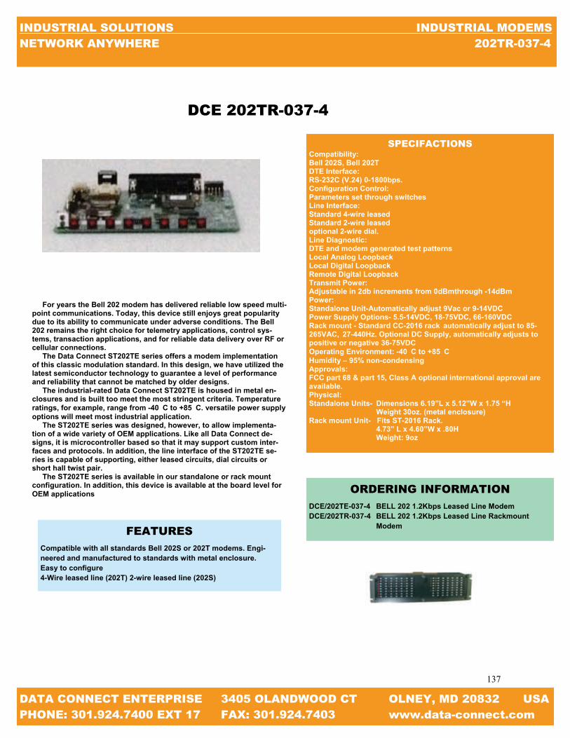
137
137
INDUSTRIAL SOLUTIONS INDUSTRIAL MODEMS NETWORK ANYWHERE 202TR-037-4
DATA CONNECT ENTERPRISE 3405 OLANDWOOD CT OLNEY, MD 20832 USA PHONE: 301.924.7400 EXT 17 FAX: 301.924.7403 www.data-connect.com
DCE 202TR-037-4
SPECIFACTIONS Compatibility: Bell 202S, Bell 202T DTE Interface: RS-232C (V.24) 0-1800bps. Configuration Control: Parameters set through switches Line Interface: Standard 4-wire leased Standard 2-wire leased optional 2-wire dial. Line Diagnostic: DTE and modem generated test patterns Local Analog Loopback Local Digital Loopback Remote Digital Loopback Transmit Power: Adjustable in 2db increments from 0dBmthrough -14dBm Power: Standalone Unit-Automatically adjust 9Vac or 9-14VDC Power Supply Options- 5.5-14VDC, 18-75VDC, 66-160VDC Rack mount - Standard CC-2016 rack automatically adjust to 85-265VAC, 27-440Hz. Optional DC Supply, automatically adjusts to positive or negative 36-75VDC Operating Environment: -40C to +85C Humidity – 95% non-condensing Approvals: FCC part 68 & part 15, Class A optional international approval are available. Physical: Standalone Units- Dimensions 6.19”L x 5.12”W x 1.75 “H Weight 30oz. (metal enclosure) Rack mount Unit- Fits ST-2016 Rack. 4.73” L x 4.60”W x .80H Weight: 9oz
For years the Bell 202 modem has delivered reliable low speed multi-point communications. Today, this device still enjoys great popularity due to its ability to communicate under adverse conditions. The Bell 202 remains the right choice for telemetry applications, control sys-tems, transaction applications, and for reliable data delivery over RF or cellular connections. The Data Connect ST202TE series offers a modem implementation of this classic modulation standard. In this design, we have utilized the latest semiconductor technology to guarantee a level of performance and reliability that cannot be matched by older designs. The industrial-rated Data Connect ST202TE is housed in metal en-closures and is built too meet the most stringent criteria. Temperature ratings, for example, range from -40C to +85C. versatile power supply options will meet most industrial application. The ST202TE series was designed, however, to allow implementa-tion of a wide variety of OEM applications. Like all Data Connect de-signs, it is microcontroller based so that it may support custom inter-faces and protocols. In addition, the line interface of the ST202TE se-ries is capable of supporting, either leased circuits, dial circuits or short hall twist pair. The ST202TE series is available in our standalone or rack mount configuration. In addition, this device is available at the board level for OEM applications
FEATURES
Compatible with all standards Bell 202S or 202T modems. Engi-neered and manufactured to standards with metal enclosure. Easy to configure 4-Wire leased line (202T) 2-wire leased line (202S)
ORDERING INFORMATION
DCE/202TE-037-4 BELL 202 1.2Kbps Leased Line Modem DCE/202TR-037-4 BELL 202 1.2Kbps Leased Line Rackmount Modem

138
138
INDUSTRIAL SOLUTIONS SERIAL DATA& MODEM EXTENSION NETWORK ANYWHERE DISTANCE CHART
SERIAL DATA & MODEM EXTENSION
MODEL MAX.
SPEED HIGH VOLT.
LOW VOLT.
PRIVATE LINE
RACK MOUNT
DIN MOUNT
WALL MOUNT RS485
DIS-TANCE PHOTO PAGE
DCE/IGV23 1200BPS X X X X X X COPPER 10 MILES
140
DCE/IG202T 1200BPS X X X X X X COPPER 10 MILES
141
DCE/IG202T-R38 1200BPS X X X COPPER 10 MILES
142
DCE/MIU/202T 1200BPS X X X COPPER 10 MILES
143
DCE/MD202T 1200BPS X X COPPER 10 MILES
144
DCE/PE202T 1200BPS X COPPER 10 MILES
145
DCE/202TE-037-4 1200BPS X X COPPER 10 MILES
147
DCE/IG96HFP 9.6KBPS X X X X X COPPER
16.1 MILES 148
DCE/DSP9612 9.6KBPS X X X X COPPER
16.1 MILES 149
DCE/MIU9.6FPD 9.6KBPS X X X COPPER
16.1 MILES 150
DCE/MD9.6FPD 9.6KBPS X X COPPER
16.1 MILES 151
DCE/PE9.6FPD 9.6KBPS X COPPER
16.1 MILES 153
DCE/MIU14.4L 14.4KBPS X X X COPPER 5 MILES
154
DCE/MIUPP14.4L 14.4KBPS X X X COPPER 5 MILES
155
DCE/MD14.4L 14.4KBPS X X COPPER 5 MILES
156
DCE/PE14.4L 14.4KBPS X COPPER 5 MILES
158
DCE/IG192HFP 19.2KBPS X X X X X COPPER
10.6 MILES 159
DCE/3600LP 33.6KBPS X X X COPPER 5 MILES
160
DCE/3342LP 33.6KBPS X X X COPPER 5 MILES
161
DCE/V.3600UI 33.6KBPS X X X X COPPER 10 MILES
162
DCE/SWM910A 115KBPS X FREQUENCY
HOPPING 62 MILES
163
DCE/SFM 1024KBPS X X X X FIBER
75 MILES 164
DCE/HS-SFM 2048KBPS X X X X FIBER
75 MILES 165
DCE/SHS-SFM 8192KBPS X X X X FIBER
75 MILES 165
DATA CONNECT ENTERPRISE 3405 OLANDWOOD CT OLNEY, MD 20832 USA PHONE: 301.924.7400 EXT 17 FAX: 301.924.7403 www.data-connect.com

139
139
INDUSTRIAL SOLUTIONS SERIAL DATA& MODEM EXTENSION NETWORK ANYWHERE IN THIS SECTION & TECHNOLOGY
DATA CONNECT ENTERPRISE 3405 OLANDWOOD CT OLNEY, MD 20832 USA PHONE: 301.924.7400 EXT 17 FAX: 301.924.7403 www.data-connect.com
TECHNOLOGY
Most Leased Line modems can be used for Serial Data Extension as Private Line, Limited dis-tance, or Short Haul modems. Our solutions allow you to transmit serial data over copper, wire-less, and fiber media and range in speed from 1200bps to 8,192,000bps and in distance from 5 to 75 miles. The modulations above 1200BPS are proprietary implementations of industry standard technologies designed for maximum Point-to-Point and Point-to-Multipoint. At Data Connect we offer a wide range of modem products to fit your network needs. We can assist you in finding a solution that maximizes your investment while providing the solutions that will benefit your customers both now and in the years to come. With the ability to match all re-quirements and standards, your choice becomes a wise choice and made easy by Data Connect expertise.
TECHNOLOGY SPEED PAGE
ITU-T V.23 MODULATION 1200BPS 140
BELL 202 MODULATION 1200BPS 141— 147
ITU-T V.29 & DSP MODULATION 9600/19200BPS 148, 149
ITU-T V.29 & FPD MODULATION 9600BPS 150—153
ITU-T V.32BIS 14400BPS 154—158
ITU-T V.34BIS 28,800BPS 160—162
FREQUENCY HOPPING 115200BPS 163
FIBER CONVERSION 1024000 / 2048000 / 8192000BPS 164—165
IN THIS SECTION

140
140
INDUSTRIAL SOLUTIONS SERIAL DATA& MODEM EXTENSION NETWORK ANYWHERE IGV.23
DATA CONNECT ENTERPRISE 3405 OLANDWOOD CT OLNEY, MD 20832 USA PHONE: 301.924.7400 EXT 17 FAX: 301.924.7403 www.data-connect.com
DCE IGV.23
The Data Connect low speed IGV.23 Industrial Grade V.23 modem is designed and manufactured for rugged industrial communication networks. The IGV.23 delivers cost effective and reliable 1200bps asynchronous solutions for point to point and multipoint connec-tivity. The IGV.23 Industrial Grade V.23 modem is ideal for industrial communication application including SCADA systems, RTUs, traffic monitor and control, and industrial and automation networks. The V.23 supports RTUs with switch selectable settings and no AT com-mand set required. The IGV.23 modem is designed to operate over 4-wire full duplex or 2-wire half duplex over unconditioned leased lines or private metallic circuits. For optimum performance, the modem employs FSK modulation to be compatible with V.23 standards, which can communicate over a variety of private transmission lines at a distance up to 10 miles. The IGV.23 Industrial Grade V.23 modem can operate over a wide range of AC or DC power supply voltages and temperatures. With Proven reliability and ease of installation the V.23 is ideal for point-to-point and point-to-multipoint polling networks, where reliability and low-network latency are critical for system performance. With its Auto-RTS mode, the modem can support DTE/RTUs with 3-wire serial interface (TD, RD, and SG) in point-to-point and multi-point polling applications. The IGV.23 industrial grade V.23 modem has selectable EIA RS-232/V.24 and RS-485 DTE support. It also features built-in diagnos-tics for local and remote testing. The configuring and options on the IG202T is provided by DIP switches and jumpers, eliminating the need for an AT command set. The IGV.23 has heavy-duty surge pro-tection at the power supply and leased line inputs. IGV.23 also uses an isolated DC to DC power converter for protecting critical DC or battery power systems.
SPECIFICATIONS DATA RATE SUPPORT: Data Speed 0-1200 bps in V.23 mode Data Format Asynchronous, transparent character format (10 or 11-bit character with 1 or 2 stop bits) MODULATION: Frequency Shift Key (FSK) V.23 Mode: Mark 1300 Hz Space 2100 Hz Soft Carrier 900 Hz TRANSMISSION LINE INTERFACE: Leased Line TELCO voice band 2 or 4 –wire leased lines Private or metallic circuits 2 or 4 –wire, 19-26 AWG Connector: 4 PIN RJ-11C modular jack Private Line at a distance up to 10 miles Transmitter output level: 0 to -12dbm, selectable DTE/RTU Interface: The modem provides serial ports to support either the RS-485 Inter-face standards RS-232 INTERFACE: Connector: D9-F Signals: RTS, CTS, CD, TD, RD, DSR, and SG RS-485 INTERFACE: Connector: RJ-11CSignals: 4-wire full-duplex TX+, TX-, RX+, RX- FRONT PANEL INDICATORS & CONTROL S: RTS, CTS, TD, CD, RD, MR, ALB, DLB TEST Switch: Push Button for Analog Loopback, Digital Loopback AC & DC POWER SUPPORT: Standalone: 10-48 VDC: 85-400 VDC, 100-240 VAC Rack mount module: plug-in RM16M modem rack POWER + CURRENT CONSUMPTION: 75 Ma @ 12 VDC 18 Ma @ 48VDC MECHANICAL: Enclosure dimensions: 4.1” (W) x 4.9” (L) x1.4” (H) 104mm (W) x 125mm (L) x36mm (H) weight: 0.51lbs, without AC power module ENVIRONMENT: Operation: -40 Degrees Celsius to + 85 Degrees Celsius Storage: -40 Degrees Celsius to + 85 Degrees Celsius Humidity: up to 95% non-condensing
ORDERING INFORMATION
DCE/IGV.23 STANDALONE (100-240 VAC) DCE/IGV.23-DC STANDALONE (10-48 VDC) DCE/IGV.23-HV STANDALONE (100-240 VAC, 85-400 VDC) DCE/IGV.23-RM RM16M RACKMOUNT MODULE DCE/IGV.23-WMB WALL-MOUNT/PANEL-MODULE DCE/IGV.23-DIN DIN-MOUNT KIT

141
141
INDUSTRIAL SOLUTIONS SERIAL DATA& MODEM EXTENSION NETWORK ANYWHERE IG202T
DATA CONNECT ENTERPRISE 3405 OLANDWOOD CT OLNEY, MD 20832 USA PHONE: 301.924.7400 EXT 17 FAX: 301.924.7403 www.data-connect.com
DCE IG202T
The Data Connect low speed IG202T Industrial Grade Bell 202 modem is designed and manufactured for rugged industrial com-munication networks. The IG202T delivers cost effective and reli-able 1200bps asynchronous solutions for point to point and multi-point connectivity. The IG202T Industrial Grade Bell 202 modem is ideal for indus-trial communication application including SCADA systems, RTUs, traffic monitor and control, and industrial and automation networks. The IG202T supports RTUs with switch selectable settings and no AT command set required. The IG202T modem is designed to oper-ate over 4-wire full duplex or 2-wire half duplex over unconditioned leased lines or private metallic circuits. For optimum performance, the modem employs FSK modulation to be compatible with Bell 202 standards, which can communicate over a variety of private trans-mission lines at a distance up to 10 miles. The IG202T Industrial Grade Bell 202 modem can operate over a wide range of AC or DC power supply voltages and temperatures. With Proven reliability and ease of installation the IG202T is ideal for point-to-point and point-to-multipoint polling networks, where reliability and low-network latency are critical for system perform-ance. With its Auto-RTS mode, the modem can support DTE/RTUs with 3-wire serial interface (TD, RD, and SG) in point-to-point and multi-point polling applications. The IG202T industrial grade Bell 202 modem has selectable EIA RS-232/V.24 and RS-485 DTE support. It also features built-in diag-nostics for local and remote testing. The configuring and options on the IG202T is provided by DIP switches and jumpers, eliminating the need for an AT command set. The IG202T has heavy-duty surge protection at the power supply and leased line inputs. IG202T also uses an isolated DC to DC power converter for protecting critical DC or battery power systems.
SPECIFICATIONS DATA RATE SUPPORT: Data Speed 0-1200 bps in Bell 202T mode Data Format Asynchro-nous, transparent character format (10 or 11-bit character with 1 or 2 stop bits) MODULATION: Frequency Shift Key (FSK) Bell 202 Mode: Mark 1200 Hz Space 2200 Hz Softt Carrier 900 Hz TRANSMISSION LINE INTERFACE: Leased Line TELCO voice band 2 or 4 –wire leased lines Private or metallic circuits 2 or 4 –wire, 19-26 AWG Connector: 4 PIN RJ-11C modular jack Private Line at a distance up to 10 miles Transmitter output level: 0 to -12dbm, selectable DTE/RTU Interface: The modem provides serial ports to support either the RS-485 Interface standards RS-232 INTERFACE: Connector: D9-F Signals: RTS, CTS, CD, TD, RD, DSR, and SG RS-485 INTERFACE: Connector: RJ-11CSignals: 4-wire full-duplex TX+, TX-, RX+, RX- FRONT PANEL INDICATORS & CONTROL S: RTS, CTS, TD, CD, RD, MR, ALB, DLB TEST Switch: Push Button for Analog Loopback, Digital Loopback AC & DC POWER SUPPORT: Standalone: 10-48 VDC: 85-400 VDC, 100-240 VAC Rack mount module: plug-in RM16M modem rack POWER + CURRENT CONSUMPTION: 75 Ma @ 12 VDC 18 Ma @ 48VDC MECHANICAL: Enclosure dimensions: 4.1” (W) x 4.9” (L) x1.4” (H) 104mm (W) x 125mm (L) x36mm (H) weight: 0.51lbs, without AC power module ENVIRONMENT: Operation: -40 Degrees Celsius to + 85 Degrees Celsius Storage: -40 Degrees Celsius to + 85 Degrees Celsius Humidity: up to 95% non-condensing
ORDERING INFORMATION
DCE/IG202T STANDALONE (100-240 VAC) DCE/IG202T-DC STANDALONE (10-48 VDC) DCE/IG202T-HV STANDALONE (100-240 VAC, 85-400 VDC) DCE/IG202T-RM RM16M RACKMOUNT MODULE DCE/IG202T-WMB WALL-MOUNT/PANEL-MODULE DCE/IG202T-DIN DIN-MOUNT KIT

142
142
INDUSTRIAL SOLUTIONS SERIAL DATA& MODEM EXTENSION NETWORK ANYWHERE IG202T-R38
DATA CONNECT ENTERPRISE 3405 OLANDWOOD CT OLNEY, MD 20832 USA PHONE: 301.924.7400 EXT 17 FAX: 301.924.7403 www.data-connect.com
DCE IG202T-R38 SPECIFACTIONS
Operation Type Data Transmission on audio frequency analog medium Media - Leased line, radio, PLC Private Line at a distance up to 10 miles Modes - asynchronous or synchronous, point-to-point, 2-wire or 4-wire -support for synchronous Indactic 33 protocol. INTERFACES DTE Interface - RS-232C, DB (female) connector Signals: DCD, RD, TD, DTR, SG, DSR, RTS, CTS, RI Character length: 5-9 data bits, 1 start & 1 stop RTS/CTS delay: adjustable by 1ms step within range of 40-6825ms option to transmit on RTS Configuration: AT command set ANALOG LINE DB15 (female) connector -600Ω or high impedance with return loss <0.2 Transmission level: 0 to -32dBM, programmable by 1dBstep Receive level: 0 to -36dBM, programmable by 1 dB step, min. -48dBM Radio control: half duplex control squelch detection POWER SUPPLY: 2-position screw plug type (for 2-2.5mm 2 wire) GENERAL LED INDICATION POWER SUPPLY: PWR, TXD, RXD, RTS, RTS, DCD 9- 18VDC, 9-12VAC, model 12 18-36VDC, 14-23VAC, model 24 36-72VDC, 25-50VAC, model 48 ISOLATION IMMUNITY to NOISE Transformer up to 1500V Peak pulse noise: 100v Peak -Effective interference at 50 Hz: 80V rms TEMPERATURE DIMENSIONS Operation and storage: -10 to 50 °C desktop: aluminum enclosure 11x30x170mm 19” rack: EUROCARD PCB, 160x100mm 3HE, 6T in 1U and 3U rack
MODULATION TRANS. RATE FREQ. DEVN. CHANL. SPACE. LOW FREQ HIGH FREQ FSK Bd Hz Hz Hz Hz ITU R.35 50 ±30 120 420 3300 ITU R.37 100 ±60 240 480 3120 ITU R.38B 200 ±90 360 540 3060 ITU R.38A 200/300 ±120 480 600 3000 ITU V.21 300 ±100 400 1080/1750 ITU V23/1/2 600/1200 ±200/400 800/1600 1500/1700 Bell 103 300 ±100 400 1170/2125 Bell 202 1200 ±500 2000 1700 QAM TRANS.RATE SYM. RATE CONST. PT. CARE.FREQ. MODE Bps Hz 4800 2400 4 1700 half duplex 7200 2400 8 1700 half duplex ITU V29 9600 2400 16 1700 half duplex
ORDERING INFORMATION DCE/IG202T-R38-DC-12 STANDALONE (9-18 VDC) DCE/IG202T-R38-DC-24 STANDALONE (18-36 VDC) DCE/IG202T-R38-DC-48 STAMDALONE (25-50 VDC) DCE/IG202TRM-R38 RACKMOUNT MODEM
The Data Connect IG202T-R38 is Bell 202 frequency shift key (FSK) and quadrature amplitude modulation (QAM) modem for asynchronous and synchro-nous data transmission in 300-3400 Hz voice band. It is highly im-mune to interference and noise and permits extensive voice-band communication link utilization. The modem supports several international standards ITU V.21, V.23, R.35, R.37, R.38A, R38B, v.29, Bell 103, Bell 202 and propriety Cegelec 1200/600Bd and Indactic 33 communication standards. The modem can operate in half or full-duplex, point-to-point or point-to-multipoint mode when using FSK modulation the receive and transmit channels may be independently set. Private linedis-tance is up to 10 miles. The modem employs advanced DSP technology, thus offering high service flexibility through programmable features. Software configuration is performed via Hayes AT command set. AT com-mands can be initiated from any terminal application using and RS-232 communication interface. Additionally, for easy firmware up-grade a bootstrap loader is provided. The modem features programmable modem capability for SCADA or power utility communication networks. It can support a range of standards including ITUR.35, R.37, R.38A, R.38B, V.21, V.23, Bell 103, and Bell 202. It is fully programmable via Hayes AT command set. The modem also features specialized line, power line carrier, or radio communication, as well as half or full-duplex operating modes. The IG202T-R38 is designed for use in SCADA systems mainly based upon power utility communication networks. Depending on modulation standards it can communicate through specialized, pri-vate or leased lines, radio links and power lines (PLC) The IG202T-R38 is available as a desktop modem or in two differ-ent types standard 19” rack, including: 1U rack with 1, 2, or 3 mo-dems per rack; 3U rack with 10, 12 or 14 modems per rack, with additional blank front plates covering unused slots. All connectors at the rear side are accessible at the back openings.

143
143
INDUSTRIAL SOLUTIONS SERIAL DATA& MODEM EXTENSION NETWORK ANYWHERE MIU-202T
DATA CONNECT ENTERPRISE 3405 OLANDWOOD CT OLNEY, MD 20832 USA PHONE: 301.924.7400 EXT 17 FAX: 301.924.7403 www.data-connect.com
DCE MIU-202T
SPECIFICATIONS
Data Rate: Asynchronous 0-1200bps over voice grade leased or pilot lines Modulation: Bell 202T Operation: phase coherent, (FSK) Full duplex over 4-wire leased or private lines Half duplex over 2-wire leased or private lines Private Line at a distance up to 10 miles (constant or switched carrier, Dip Switch selectable) Power supply: 48VAC/DC (Optional 9- 36VDC) Power consumption: 15mA @ 48VD; 7.5mA @ 115CDV; 7.5mA @ 125VDC Digital Port: RS232 with DB9 Connector Analog Port: RJ11 Power connector: 3-pin with screw terminals for customer supplied cable Case Size: 5-3/8” x 4” x 1-3/8” Surge protection: (Power Line) - 8kV [Exceeds IEC801-4] Surge protection: (Analog Line) - 3.75kVac Operation equipment -40C to +85C, 0 to 95% humidity (non-condensing)
Carrier Frequencies: Bell 202T… Mark: 1200Hz ± 0.1% Space: 2200Hz ± 0.1%
Bell 202T continues to be the standard of choices in many utility and industrial multi-drop data communications applications. The Data Connect Enterprise MIU202T can be powered from a wide range of DC and AC voltages, is surge protected on both the power and analog lines, and will operate in extreme heat and cold. Ideal for multi-drop applications over leased lines and private lines at a distance up to 10 miles.. The MIU202T is a Bell Standard 202T modem designed for asyn-chronous operation at 0 to 1200 bps over voice grade lines and pilot wires. The modem is intended for use on leased lines and private lines and provides half-duplex communications on 2-wire lines, or full-duplex on 4-wire. Most modem manufactures have abandoned the Bell 202T in favor of the much higher speed modulation preferred in dial-up systems. However, Bell 202T remains the standard of choice in many utility and industrial applications where relatively small amounts of data are to be transmitted in multi-point networks. To meet this continued demand, Data Connect Enterprise has added the MIU202T to its range of Communications Interface Units (see separate brochure). The MIU202T can be powered from any AC or DC voltage in the range of 48V to 220V.A 9-36VDC version is also available. It is de-signed to work extended temperatures ranging from -40C to +80C, and its surge protected to 8kV, double the voltage requirements of IEC801-4 standard. All of this is bundled in a 5-3/8“x 4” x 1-3/8,’ non metallic enclo-sure, suitable for desktop or wall mounting. Rack mount cards are also available for Data Connect Enterprise “Myriad” system (see separate brochure)
FEATURES
0-1200 bps, leased AC/DC powered substation hardened Bell 202T 0-1200 bps over voice grade leased lines Point-to-point or multi-point 48 to 220V AC/DC Power Supply 9-36VDC optional power supply IEC901-4 surge protection -40C to +85C operating Temp.
For meters, RTUs, SCADA, etc.
ORDERING INFORMATION DCE/MIU-202T BELL 202 1.2Kbps Leased Line Modem DCE/MIU-202T-LV BELL 202 1.2Kbps Leased Line Modem Low Voltage
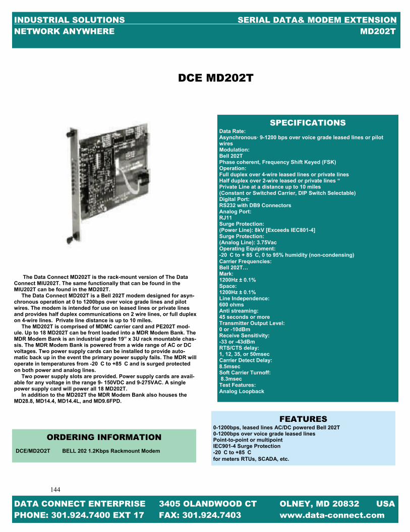
144
144
INDUSTRIAL SOLUTIONS SERIAL DATA& MODEM EXTENSION NETWORK ANYWHERE MD202T
DCE MD202T
The Data Connect MD202T is the rack-mount version of The Data Connect MIU202T. The same functionally that can be found in the MIU202T can be found in the MD202T. The Data Connect MD202T is a Bell 202T modem designed for asyn-chronous operation at 0 to 1200bps over voice grade lines and pilot wires. The modem is intended for use on leased lines or private lines and provides half duplex communications on 2 wire lines, or full duplex on 4-wire lines. Private line distance is up to 10 miles. The MD202T is comprised of MDMC carrier card and PE202T mod-ule. Up to 18 MD202T can be front loaded into a MDR Modem Bank. The MDR Modem Bank is an industrial grade 19” x 3U rack mountable chas-sis. The MDR Modem Bank is powered from a wide range of AC or DC voltages. Two power supply cards can be installed to provide auto-matic back up in the event the primary power supply fails. The MDR will operate in temperatures from -20C to +85C and is surged protected on both power and analog lines. Two power supply slots are provided. Power supply cards are avail-able for any voltage in the range 9- 150VDC and 9-275VAC. A single power supply card will power all 18 MD202T. In addition to the MD202T the MDR Modem Bank also houses the MD28.8, MD14.4, MD14.4L, and MD9.6FPD.
SPECIFICATIONS Data Rate: Asynchronous· 9-1200 bps over voice grade leased lines or pilot wires Modulation: Bell 202T Phase coherent, Frequency Shift Keyed (FSK) Operation: Full duplex over 4-wire leased lines or private lines Half duplex over 2-wire leased or private lines “ Private Line at a distance up to 10 miles (Constant or Switched Carrier, DIP Switch Selectable) Digital Port: RS232 with DB9 Connectors Analog Port: RJ11 Surge Protection: (Power Line): 8kV [Exceeds IEC801-4] Surge Protection: (Analog Line): 3.75Vac Operating Equipment: -20C to + 85C, 0 to 95% humidity (non-condensing) Carrier Frequencies: Bell 202T… Mark: 1200Hz ± 0.1% Space: 1200Hz ± 0.1% Line Independence: 600 ohms Anti streaming: 45 seconds or more Transmitter Output Level: 0 or -10dBm Receive Sensitivity: -33 or -43dBm RTS/CTS delay: 1, 12, 35, or 50msec Carrier Detect Delay: 8.5msec Soft Carrier Turnoff: 8.3msec Test Features: Analog Loopback
DATA CONNECT ENTERPRISE 3405 OLANDWOOD CT OLNEY, MD 20832 USA PHONE: 301.924.7400 EXT 17 FAX: 301.924.7403 www.data-connect.com
FEATURES 0-1200bps, leased lines AC/DC powered Bell 202T 0-1200bps over voice grade leased lines Point-to-point or multipoint IEC901-4 Surge Protection -20C to +85C for meters RTUs, SCADA, etc.
ORDERING INFORMATION
DCE/MD2O2T BELL 202 1.2Kbps Rackmount Modem

145
145
INDUSTRIAL SOLUTIONS SERIAL DATA& MODEM EXTENSION NETWORK ANYWHERE MDR
DATA CONNECT ENTERPRISE 3405 OLANDWOOD CT OLNEY, MD 20832 USA PHONE: 301.924.7400 EXT 17 FAX: 301.924.7403 www.data-connect.com
DCE MDR
FEATURES
18 Modem Slots Dial & Leased Line Modems V.22, 202T, 9.6FPD, V.32bis, V.34 Hayes AT Compatibility Full Array of LEDs Standard 19” x 5.25” (3U) Euro-Chassis AC or DC Power from 9 to 300VAC or VDC Dual Power Supplies with Full Redundancy Ideal for SCADA Master Stations
The Data Connect MDR Modem Chassis is designed to house eighteen (18) DCE MD Modem Cards and two (2) DCE MDP Power Supplies. The DCE MDR Modem Chassis is hardened industrial grade, 19” wide, 3U height (5.25”H), and constructed heavy gauge steel with plating for corrosion resistance. The DCE MD Modem Cards are comprised of a DCE MDMC Modem Carrier Card and a DCE PE OEM Card. The DCE MD202T (Bell 202T), MD9.6FPD (Proprietary), MD2.4 (V.22), MD14.4 (V.32bis), MD14.4L (V.32bis), and MD28.8 (V.34) operate within the DCE MDR Modem Chassis and are hot-swappable. Any mix of the DCE MD modems can be utilized simultaneously. Two (2) DCE MDP Power Supplies Cards provide full redundancy and are available for any voltage in the range of 9-150VDC and 9-275VAC. A single DCE MDP Power Supply Card powers eighteen (18) Modem Cards. A second DCE MDP Power Supply Card, if in-stalled, provides automatic backup in the event of a failure of the primary DCE MDP Power Supply Card.
SPECIFICATIONS EIA Standards Compliant with EIA Standard EIA-310-C Modem Interface Connectors (Rear) Serial RS232: DB25F Analog Port: RJ11 LEDs (Front) (Top to bottom) DTR: Data Terminal Ready TXD: Transmit Data RXD: Receive Data MR: Modem Ready CD: Carrier Detect RTS: Request to Send CTS: Clear to Send RI: Ring Indicator Power Requirements AC Power: 9 to275VAC – Fused Socket (IEC 320) DC Power: 9 to 150VDC – Screw Terminals – 9 to 150VDC Dimensions Width: 19” Depth: Height: 5.25” (3U) Environmental Operating Temperature: -20 to +85 Degrees Celsius

146
146
INDUSTRIAL SOLUTIONS SERIAL DATA& MODEM EXTENSION NETWORK ANYWHERE PE202T
DATA CONNECT ENTERPRISE 3405 OLANDWOOD CT OLNEY, MD 20832 USA PHONE: 301.924.7400 EXT 17 FAX: 301.924.7403 www.data-connect.com
DCE PE202T
To service the growing need for efficient, reliable data communica-tion in harsh environments of utility substations and industrial facili-ties, DCE has developed a series of OEM PCB modems that can oper-ate at 5V logic (TTL) or simple send and receive signals and survive high surge levels and extreme heat and cold. All this without compro-mising the performance expected from state-of-the-art communication devices. With the rapid move toward “intelligent” substations, where meters, relays, RTUs, SCADA systems, etc. are able to “talk” to a re-mote operator, communication devices such as modems are moving off the desktop and into the meters, RTUs, and SCADA units where the conveniences of a standalone modem is unacceptable. Data Connect Enterprise has addressed this problem by developing the PE2.4, 9.6FPD, 14.4, 14.4L, 202T, and 28.8 OEM modems designed specifically for harsh environments. The PE OEM modems are highly sophisticated full duplex, V.22bis data modems that are designed to interface with RS232, RS485 (external device), 5V logic (TTL) or simple send and receive signals. The PE2.4, 14.4, and 28.8 OEM modems operate at full or half duplex on a dial up line. The PE202T, 14.4L, and 9.6FPD OPM modems operate full or half duplex on 2 or 4 wire leased lines. The PE OEM PECs can be found in the MIU modems, MD modem cards, and the MIU Power Port modems.
SPECIFICATIONS
Modem Line Speeds: 0-1200bps Standard: Bell 202T Transmission Line: 4-wire or private lines Compatibility: Hayes Extended AT Command Set
FEATURES
Modem Interface Units 5V logic (TTL) Simple send and receive signals 1200kbps 2/4-Wire Leased Line modem 5V logic (TTL) power supply IEC801-4 surge protection -40°C to +85°C operating temperature
ORDERING INFORMATION
DCE/PE202T 2/4-WIRE LEASED LINE PCB

147
147
INDUSTRIAL SOLUTIONS SERIAL DATA& MODEM EXTENSION NETWORK ANYWHERE 202TE-037-4
DATA CONNECT ENTERPRISE 3405 OLANDWOOD CT OLNEY, MD 20832 USA PHONE: 301.924.7400 EXT 17 FAX: 301.924.7403 www.data-connect.com
DCE 202TE-037-4
SPECIFACTIONS Compatibility: Bell 202S, Bell 202T DTE Interface: RS-232C (V.24) 0-1800bps. Configuration Control: Parameters set through switches Line Interface: Standard 4-wire leased Standard 2-wire leased optional 2-wire dial. Private Line at a distance up to 10 miles Line Diagnostic: DTE and modem generated test patterns Local Analog Loopback Local Digital Loopback Remote Digital Loopback Transmit Power: Adjustable in 2db increments from 0dBmthrough -14dBm Power: Standalone Unit-Automatically adjust 9Vac or 9-14VDC Power Supply Options- 5.5-14VDC, 18-75VDC, 66-160VDC Rack mount - Standard CC-2016 rack automatically adjust to 85-265VAC, 27-440Hz. Optional DC Supply, automatically adjusts to positive or negative 36-75VDC Operating Environment: -40C to +85C Humidity – 95% non-condensing Approvals: FCC part 68 & part 15, Class A optional international approval are available. Physical: Standalone Units- Dimensions 6.19”L x 5.12”W x 1.75 “H Weight 30oz. (metal enclosure) Rack mount Unit- Fits ST-2016 Rack. 4.73” L x 4.60”W x .80H Weight: 9oz
For years the Bell 202 modem has delivered reliable low speed multi-point communications. Today, this device still enjoys great popularity due to its ability to communicate under adverse conditions. The Bell 202 remains the right choice for telemetry applications, control sys-tems, transaction applications, and for reliable data delivery over RF or cellular connections. The Data Connect ST202TE series offers a modem implementation of this classic modulation standard. In this design, we have utilized the latest semiconductor technology to guarantee a level of performance and reliability that cannot be matched by older designs. The industrial-rated Data Connect ST202TE is housed in metal en-closures and is built too meet the most stringent criteria. Temperature ratings, for example, range from -40C to +85C. versatile power supply options will meet most industrial application. The ST202TE series was designed, however, to allow implementa-tion of a wide variety of OEM applications. Like all Data Connect de-signs, it is microcontroller based so that it may support custom inter-faces and protocols. In addition, the line interface of the ST202TE se-ries is capable of supporting, either leased circuits, dial circuits or short hall twist pair. Private line distance is up to 10 miles. The ST202TE series is available in our standalone or rack mount configuration. In addition, this device is available at the board level for OEM applications
FEATURES
Compatible with all standards Bell 202S or 202T modems. Engi-neered and manufactured to standards with metal enclosure. Easy to configure 4-Wire leased line (202T) 2-wire leased line (202S)
ORDERING INFORMATION
DCE/202TE-037-4 BELL 202 1.2Kbps Leased Line Modem DCE/202TR-037-4 BELL 202 1.2Kbps Leased Line Rackmount Modem

148
148
INDUSTRIAL SOLUTIONS SERIAL DATA& MODEM EXTENSION NETWORK ANYWHERE IG96HFP
The IG96HFP industrial grade 9.6 kbps hyper fast modem is designed to operate over 4-wire full duplex or 2 wire half duplex unconditioned leased lines or private metallic circuits. For optimum performance, the modem em-ploys QAM modulations along with its adaptive equalizers to communicate over a variety of private transmissions lines at a distance up to 16.1 miles. The IG96HFP supports DTE/RTUs with an EIA RS-232 andRS-485 serial port at speeds of 9600, 4800, 2400 and 1200 bps. EIA its Auto-RTS mode, the modem can support DTE/RTUs with 3-wire serial interface (TD, RD, and SG) in multi-point polling applications. The triple mode capability allows the IG96HFP industrial grade 9.6 kbps hyper fast poll modem to communicate with the older generation DSP9612FP at up to 9600 kbps and both the Bell 202T and V.23 FSK modem at up to 1200 bps. The IG96HFP industrial grade 9.6 kbps hyper fast poll modem to range AC or DC power supply voltage and temperatures, with proven reliability and ease of installation, the IG96HFP is deal for point-to-multipoint polling networks, where fast training time and low-network latency are critical for system performance.
ORDERING INFORMATION
DCE/IG96HFP STANDALONE (100-240VAC) DCE/IG96HFP-LV STANDALONE (10-48 VDC) DCE/IG96HFP-HV STANDALONE (100-240 VAC, 85-400 VDC) DCE/IG96HFP-RM RM16M RACK-MOUNT MODULE DCE/96HFP-WMB WALL-MOUNT/PANEL-MOUNT KIT DCE/IG96HFP-DIN DIN RAIL MOUNTING KIT
SPECIFICATIONS
TRIPLE MODE: Hyper Fast Poll mode at 9600, 17.5 ms RTS-CTS delay QAM mode at 9600/4800/4200bps 23 ms RTS-CTS delay FSK mode for Bell 202T (0-1800) modes DTE/RTU INTERFACE: RS-232 interface with full control signals support (db-9F) RS-485/RS422 support, 4-wire F.D., or 2-wire H.D Auto RTS and forced RTS options to support 3-wire interface LEASED LINE INTERFACE: Telco 2- or 4- wire conditioned or unconditioned lines private metallic 2 or 4 wire circuits. Cable equalizer for long distance over standard cables Private Line at a distance up to 16.1 miles MECHANICAL: Enclosure Dimensions: 5.0” (W) x 6.75” (L) x 1.3” (H). 127mm (W) x 172mm (L) x 33mm (H) DIAGNOSTICS: Local or remote Analog + digital loopback Eight (8) front panel LEDs for status monitoring AC and DC POWER SUPPORT: Standalone: 10-48 VDC, 85-400 VDC, 100-240 AC Rack Mount modules: Plug-in RM16M modem rack ENVIRONMENTAL: Operating temperatures:-40 to 85 degrees Celsius storage tem-perature:-40 to 100 degrees Celsius humidity: up to 95% non-condensing OPTIONAL MOUNTING KITS: Wall-mount or panel-mount kit DIN rail mounting kit POWER+ CURRENT CONSUMPTION: 125 mA @ 12 VDC 28.0 mA @ 48 VDC
DCE IG96HFP
DATA CONNECT ENTERPRISE 3405 OLANDWOOD CT OLNEY, MD 20832 USA PHONE: 301.924.7400 EXT 17 FAX: 301.924.7403 www.data-connect.com

149
149
INDUSTRIAL SOLUTIONS SERIAL DATA& MODEM EXTENSION NETWORK ANYWHERE DSP9612
DATA CONNECT ENTERPRISE 3405 OLANDWOOD CT OLNEY, MD 20832 USA PHONE: 301.924.7400 EXT 17 FAX: 301.924.7403 www.data-connect.com
The DCE Fast Poll DSP9612 is a triple mode, full featured 9600 QAM fast poll, ITU V.23 and Bell 202T leased line or private wire modem with the fast-est training time in the industry: 23msec RTS?CTS delay at 9600bps and 8ms in Bell 202T mode. The DSP9612 is ideal for utility and industrial auto-mation multi-dropping applications, where an unlimited number or drops is desirable at ranges up to 16 miles (26km), including SCADA systems, traffic automation and oil or gas automation products. The DSP9612 is a modem designed for 4-wire full duplex or 2 wire half-duplex operation over a voice-band leased line or private copper wire. The modem designed utilizes the latest digital-signal processing (DSP) technol-ogy to achieve high performance with an adaptive equalizer for the best operation on the poor unconditional lines. In Fast Poll Mode (9600/4800bps), the dsp9612 employs a propriety modulation and encoding scheme to achieve fast modem training time in V.23 or Bell 202T mode, the modem is also backward compatible with V.23 (0-1800bps) modems. Ideal for systems where fast response, shirt training time and low throughput is required, the Flash poll is optimized for fast receiver equal-izer training and extremely low through put delay. The triple mode capability allows the DSP9612 to communicate with existing V.23 or Bell 202T modems at up to 1800bps, which can then be upgraded later to DCE DSP9612 Fast poll standalone modems and switched to 9600bps. Three models are available: Rack mount (RM) for insertion into RM16 nest, stand alone AC/DC powered (FP) and standalone low Voltage DC powered (LV). Auto RTS is a new feature allowing multi-drop for devices with 3 wire data interfaces and no control signals (no RTS signal) required.
FEATURES
Fast poll modems are industrial grade modems designed for harsh environ-mental conditions [-40 to 85 degrees Celsius] with ultra fast polling times. Triple mode: QAM 9600 or 4800 bps, ITU V.23 and Bell202T. Fast Training modem equalizer with 23msec RTS/CTS delay @ 9600/4800bps. DSP designed with automatic adaptive equalizer. Leased-line or private wire interfaces. Line and power protected with heavy-duty surge protection. Stand alone or nest card for RM16 nest. All settings are DIP switch selectable with no software commands Auto RTS allows multi-drop for devices with three wire data interface.
SPECIFICATIONS
DATA RATE Fast Poll Mode: 9600 or 4800 bps asynchronous, +1% -2.5% Bell 202T Mode: 0-1800 bps asynchronous V.23 Mode: 0-1200bps asynchronous DATA FORMAT - 8 or 9 data bits with 1 more stop bits LINE REQIREMENTS - TELCO Voice band 2 or 2 wire leased line. Private metal RS-232 (DTE) INTERFACE Signal Name in/out DP25 PIN Description Earth GND1 Earth Ground TXD Input 2 Transmit Data RXD Output 3 Receive Data RTS Input 4 Request to Send CTS Output 5 Clear to Send DSR Output 6 Data Set Ready (Modem Ready) SG GND7 Signal Ground DCD Output 8 Data Carrier Detected DTR Input20 Data Terminal Ready (HOST READY) DSR Input23 Data Select Rate OPERATING MODES - 2-wire half duplex or 4-wire full duplex MODULATION - DCE Propriety (Fast Poll Mode) EQUALIZER - Automatic, adaptive in Fast Poll Mode, Fixed compromised in FSK mode TRAINING TIME (RTS to CTS Delay) Fast Poll Mode: 23ms V23 33ms Bell 202T Mode:8, 33, 59, 219 ms CABLE EQUALIZER - Fixed transmitter and receiver cable equalizer Private Line at a distance up to 16.1 miles POWER SUPPLY (BY MODEL) DSP9612RM, powered from RM16 Rack DSP9612LV, 10 to 53 VDC DSP9612FP, 85 to 265 VAC or 85 to 400 VDC SURGE PROTECTION - Provided at power line and leased line; Up to 15KV (Standalone Version) CARRIER CONTROL - Constant or switched, DIP Switch available SYNCHRONIZATION LOSS RECOVERY - Built in Train on Data for Fast Poll TRANSMIT OUTPUT LEVEL +3dbm, to -14dbm, 1dbm step (Dip Switch avail-able) OPERATING TEMPERATURE - -40 Degrees Celsius to 85 Degrees Celsius RM FORM FACTOR - Rack-Mount Modem card for the DCE and the Motorola/UDS MD16M Universal Data Shelf Dimension 9” x 6.25 x 0.87” Weight 8oz. LV AND FP FORM FACTOR - Aluminum and Steel Case Dimensions: 5.7” x 8.3” x1.5” (144.78mm x 210.82mm x 38.1mm) Weight: 1.9lb (227 grams) DIAGNOSTIC FEATURES Front panel LED for status monitoring: Power (PWR), Request to send (RTS), Clear to Send (CTS), Transmit Data (TXD), Receive Data (RXD), Data Carrier Detect (DCD), Data Set Ready (DSR), Analog Loopback (ALB), Digital Loopback (DLB) Front Panel loopback control for testing: Local Analog Loopback (ALB), Local Digital Loopback (DLB), Remote Digital Loopback (RDL)(except V.23 Mode) DIAGNOSTIC FEATURES Front panel LED for status monitoring: Power (PWR), Request to Send (RTS), Clear to Send (CTS), Transmit Data (TD), Receive Data (RD), Data Carrier Detect (DCD), Data Set Ready (DSR), Analog Loopback, Digital Loopback Front Panel loopback control for testing: Local Analog Loopback, Local Digital Loopback, Remote Digital Loopback (except V.23 Mode)
DCE DSP9612

150
150
INDUSTRIAL SOLUTIONS SERIAL DATA& MODEM EXTENSION NETWORK ANYWHERE MIU-9.6FPD
DATA CONNECT ENTERPRISE 3405 OLANDWOOD CT OLNEY, MD 20832 USA PHONE: 301.924.7400 EXT 17 FAX: 301.924.7403 www.data-connect.com
To service the growing need for efficient, reliable data communication in harsh environments of utility substations and industrial facilities, has developed a 9600 Fast Poll modem that can operate from various AC/DC power supplies and survive high surge levels and extreme heat and cold. All this without compromising the performance expected from state-of-the-art communication devices. With the rapid move toward “intelligent” substations, where meters, re-lays, RTU’s, SCADA systems, etc are able to “talk” to a remote operator, communication devices such as modems are moving off the desktop and into the field, where the conveniences of 115VAC power outlets and cli-mate control are usually hard to find. Data Connect Enterprise has addressed this problem by developing the 9.6FPD series modem designed specifically for harsh environments. The 9.6FPD series modem is a highly sophisticated full duplex V.29 or V.27 data modem that is designed to interface with RS232, RS485 (external device), 5V logic (TTL) or simple send and receive signals. The 9.6FPD operates at full or half duplex 2-wire or 4-wire lease line and in multi-polling circuits. The 9.6FPD is powered from a unique power supply that enables it to operate on any AC or DC voltage ranging from 48V to 240V. A low voltage version (9-36VDC) is also available. The 9.6FPD is designed to work in temperatures from 40°C to 85°C, and is surge protected on both the power analog lines. The 9.6FPD is bundled in a 5-3/8” X 1-3/8” non-metallic enclosure, suit-able for desktop or wall mounting.
FEATURES Modem Interface Units AC/DC Powered Substation Hardened Communication Interface Units 9.6 kbps 2 & 4-Wire Leased Line Modem 48 to 220 AC/DC Power Supply IEC801-4 Surge Protection -40°C to + 85°C Operating Temperature For Meters, Relays, SCADA etc.
GENERAL SPECIFICATIONS Modem Line Speeds: Asynchronous 4800, 9600, 14000bps DTE Rates: Above modem line speeds (IE; with data compression) 4800, 9600, 14000 Standards: V.27 & V.29 Transmission Line: 2 & 4 Wire Leased Line Power Supply 48VAC/DC to 220VA/DC (Optional 9-36VDC) Power Connector: 4-ft AC Cord with 3-Pin Screw Terminal connector included Case size: 5-3/8” X 4” X 1-3/8” Digital Port: RS232 with DB9 Connector Analog Port: RJ11 Modular Jack Surge Protection: 3.75VAC Environment: -40°C to +85°C, 0to 95% humidity (non-condensing) Certifications: FCC Part 68, Industry Canada
ORDERING INFORMATION DCE MIU9.6FPD 2-4 – wire leased line standalone DCE MIU9.6FPD-LV 2-4-wire leased line standalone low voltage
DCE MIU-9.6FPD

151
151
INDUSTRIAL SOLUTIONS SERIAL DATA& MODEM EXTENSION NETWORK ANYWHERE MD-9.6FPD
DATA CONNECT ENTERPRISE 3405 OLANDWOOD CT OLNEY, MD 20832 USA PHONE: 301.924.7400 EXT 17 FAX: 301.924.7403 www.data-connect.com
The Data Connect MD-9.6FPD is the rack mount version of the Data Connect MIU-9.6FPD and MIU-9.6FPD-LV. The same functionally that it can be found in the MIU-9.6FPD and MIU-9.6FPD-LV can be found in the MD-9.6FPD. The Data Connect MD-9.6FPD is a Bell V.29 modem designed for asynchronous operation at 0 to 9600bps over voice grade lines. The modem is intended for use on two or four wire Leased Lines. Private line distance is up to 16.1 miles. The MD-9.6FPD is comprised of MDMC carrier card and PE-9.6FPD module. Up to 18 MD-9.6FPD can be front loaded into a MDR Modem Bank. The MDR Modem Bank is an industrial grade 19” X 3U rack mount-able chassis. The MDR Modem Bank is powered from a wide range of AC or DC voltages. Two power supply cards can be installed to provide automatic back up in the event the primary power supply fails. The MDR will operate in temperatures from -20˚C to +85˚C and is surge pro-tected on both power and analog lines. Two power supply slots are provided. Power supply cards are avail-able for any voltages in the range 9-150VDC and 9-275VAC. A single power supply card will power all 18 MD14.4L. In addition to MD14.4L the MDR Modem Bank also houses the MD28.8, MD14.4, MD14.4L, and MD202T.
FEATURES
14.4kbps 2 or 4-wire Leased Line modem IEC801-4 surge protection -20˚C to +80˚C Operating Temperature Works with Meters, Relays, SCADA, etc.
SPECIFICATIONS DTE Rates: Asynchronous 14000, 9600, 4800, 1200, 300bps Standards: V.32bis, V.32, V.22bis, V.22, Bell212A, and Bell 103 Transmission Line: 2- and 4-wire leased line Private Line at a distance up to 10 miles Compatibility: Hayes Extended AT Command Set Digital Port: RS232 with DB9 connector Analog Port: RJ11 Modular Jack Surge Protection: (Power Line) 8kV [Exceeds IE801-4] (20Kv IE801-5 available if required) Surge Protection 3.75VAC Environment: -40˚C or + 85˚C, 0 to 95% humidity (non-condensing) Certification: FCC Part 68, Industry Canada
DCE MD-9.6FPD
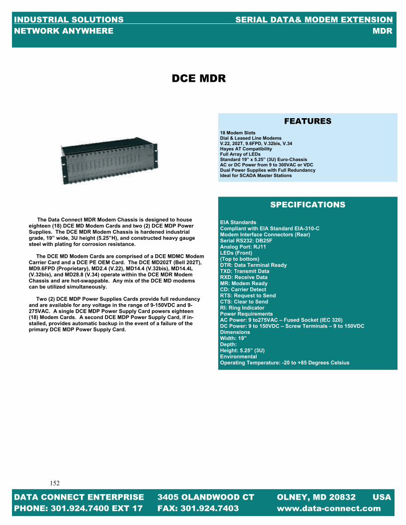
152
152
INDUSTRIAL SOLUTIONS SERIAL DATA& MODEM EXTENSION NETWORK ANYWHERE MDR
DATA CONNECT ENTERPRISE 3405 OLANDWOOD CT OLNEY, MD 20832 USA PHONE: 301.924.7400 EXT 17 FAX: 301.924.7403 www.data-connect.com
DCE MDR
The Data Connect MDR Modem Chassis is designed to house eighteen (18) DCE MD Modem Cards and two (2) DCE MDP Power Supplies. The DCE MDR Modem Chassis is hardened industrial grade, 19” wide, 3U height (5.25”H), and constructed heavy gauge steel with plating for corrosion resistance. The DCE MD Modem Cards are comprised of a DCE MDMC Modem Carrier Card and a DCE PE OEM Card. The DCE MD202T (Bell 202T), MD9.6FPD (Proprietary), MD2.4 (V.22), MD14.4 (V.32bis), MD14.4L (V.32bis), and MD28.8 (V.34) operate within the DCE MDR Modem Chassis and are hot-swappable. Any mix of the DCE MD modems can be utilized simultaneously. Two (2) DCE MDP Power Supplies Cards provide full redundancy and are available for any voltage in the range of 9-150VDC and 9-275VAC. A single DCE MDP Power Supply Card powers eighteen (18) Modem Cards. A second DCE MDP Power Supply Card, if in-stalled, provides automatic backup in the event of a failure of the primary DCE MDP Power Supply Card.
FEATURES
18 Modem Slots Dial & Leased Line Modems V.22, 202T, 9.6FPD, V.32bis, V.34 Hayes AT Compatibility Full Array of LEDs Standard 19” x 5.25” (3U) Euro-Chassis AC or DC Power from 9 to 300VAC or VDC Dual Power Supplies with Full Redundancy Ideal for SCADA Master Stations
SPECIFICATIONS EIA Standards Compliant with EIA Standard EIA-310-C Modem Interface Connectors (Rear) Serial RS232: DB25F Analog Port: RJ11 LEDs (Front) (Top to bottom) DTR: Data Terminal Ready TXD: Transmit Data RXD: Receive Data MR: Modem Ready CD: Carrier Detect RTS: Request to Send CTS: Clear to Send RI: Ring Indicator Power Requirements AC Power: 9 to275VAC – Fused Socket (IEC 320) DC Power: 9 to 150VDC – Screw Terminals – 9 to 150VDC Dimensions Width: 19” Depth: Height: 5.25” (3U) Environmental Operating Temperature: -20 to +85 Degrees Celsius

153
153
INDUSTRIAL SOLUTIONS SERIAL DATA& MODEM EXTENSION NETWORK ANYWHERE MIU14.4L
DATA CONNECT ENTERPRISE 3405 OLANDWOOD CT OLNEY, MD 20832 USA PHONE: 301.924.7400 EXT 17 FAX: 301.924.7403 www.data-connect.com
To service the growing need for efficient, reliable data communication in harsh environments of utility substations and industrial facilities, DCE has developed a series of OEM PCB modems that can operate at 5V logic (TTL) or simple send and receive signals and survive high surge levels and extreme heat and cold. All this without compromising the perform-ance expected from state-of-the-art communication devices. With the rapid move toward “intelligent” substations, where meters, relays, RTUs, SCADA systems, etc. are able to “talk” to a remote operator, communica-tion devices such as modems are moving off the desktop and into the meters, RTUs, and SCADA units where the conveniences of a standalone modem is unacceptable. Private line distances up to 16.1 miles. Data Connect Enterprise has addressed this problem by developing the PE2.4, 9.6FPD, 14.4, 14.4L, 202T, and 28.8 OEM modems designed specifically for harsh environments. The PE OEM modems are highly sophisticated full duplex, V.22bis data modems that are designed to interface with RS232, RS485 (external de-vice), 5V logic (TTL) or simple send and receive signals. The PE2.4, 14.4, and 28.8 OEM modems operate at full or half duplex on a dial up line. The PE202T, 14.4L, and 9.6FPD OPM modems operate full or half duplex on 2 or 4 wire leased lines. The PE OEM PECs can be found in the MIU modems, MD modem cards, and the MIU Powerport modems.
FEATURES
Modem Interface Units 5V logic (TTL) Simple send and receive signals 2400kbps 2-wire dial-up line modem 5V logic (TTL) power supply IEC801-4 surge protection -40°C to +85°C operating temperature For meters, relays, SCADA etc.
PE9.6FPD Modem Line Speeds: Asynchronous 4800, 9600, 14000bps Standards: V.27, V.29 Transmission Line: 2 & 4 wire leased lines Private Line at a distance up to 16.1 miles Compatibility: Hayes Extended AT Command Set 5V logic (TTL)
ORDERING INFORMATION
DCE/PE9.6FPD 2 & 4 wire leased line PCB
DCE PE-9.6FPD

154
154
INDUSTRIAL SOLUTIONS SERIAL DATA& MODEM EXTENSION NETWORK ANYWHERE MIU-PP14.4L
DATA CONNECT ENTERPRISE 3405 OLANDWOOD CT OLNEY, MD 20832 USA PHONE: 301.924.7400 EXT 17 FAX: 301.924.7403 www.data-connect.com
DCE MIU14.4L
To service the growing need for efficient, reliable data communica-tion in harsh environments of utility substation and industrial facilities, has developed a 14400bps modem that can operate from various AC/DC power supplies and survive high surge levels and extreme heat and cold. All this without compromising the performance expected from state-of-the-art communications devices. With the rapid move toward “intelligent” substations, where meters, relays, RTUs, SCADA systems, etc. are able to “talk” to a remote opera-tor, communication devices such as modems are moving off the desk-top and into the field, where the convenience of 115VAC power outlets and climate control are usually hard to find. Data Connect Enterprise has addressed this problem by developing the MIU14.4 series modem designed specifically for harsh environ-ments. The MIU14.4 series modem is highly sophisticated full duplex, V.32BIS data modem that designed to interface with RS232, RS485 (external device), 5V logic (TTL) or simple send and receive signals The MIU14.4L series modem operates on 2-wire and 4-wire leased line sys-tems. Private line distance is up to 5 miles. The MIU14.4 series modem is powered from unique power supply that enables it to operate on any AC or DC voltage ranging from 48V to 240V. A low voltage version (9-36VDC) is also available. The MIU14.4 series modem is designed to work in temperatures from 40˚C to 85˚C and is surge protected on both the power and analog lines. The MIU14.4 series modem is bundled in a 5-3/8” x 1-3/8” non-metallic enclosure, suitable for desktop or wall mounting. Also see our Data sheets on the MIU/power-port low voltage mo-dems, the “Myriad” Rack Mount Modem, MIU202T (Bell), MIU28.8 and MIU9.6FPD modems.
FEATURES
Modem Interface Units AC/DC Powered Substation Hardened Communication Interface Units 14.4kbps 2 & 4-wire leased line modem 48 to 220 AC/DC Power Supply IEC801-4 Surge Protection -40˚C to +85˚C Operating Temperature For Meters, Relay, SCADA etc.
SPECIFICATIONS Modem Line Speeds: Asynchronous 14400, 9600, 4800, 1200, 300bps DTE Rates: Above modem line speeds (IE; with data compression) 57.6, 38.4 19.2kbps Standards: V.32bis, V.32, V.22bis, V.22, Bell 212A, and Bell 103 Transmission Line: 2 & 4-wire leased line Private Line at a distance up to 5 miles Compatibility: Hayes Extended AT command set Power Supply: 48VAC/DC to 220VAC/DC (Optional 9-36VDC) Power Connector: 4-ft AC Cord with 3-pin screw terminal connector included Case size: 5-3/8” x 4” x 1-3/8” Digital Port: RS232 with DB9 connector Analog Port: RJ11 Modular Jack Surge Protection: (power line) 8kV [exceeds IEC801-4] (20kV IE801-5 available if required) Surge Protection: 3.75VAC Environment: -40˚C to +85˚C, 0 to 95% humidity (non- condensing) Certifications: FCC Part 68, Industry Canada

155
155
INDUSTRIAL SOLUTIONS SERIAL DATA& MODEM EXTENSION NETWORK ANYWHERE PE-9.6FPD
DATA CONNECT ENTERPRISE 3405 OLANDWOOD CT OLNEY, MD 20832 USA PHONE: 301.924.7400 EXT 17 FAX: 301.924.7403 www.data-connect.com
DCE MIU-PP14.4L
FEATURES
Modem Interface Units AC/DC Powered Substation Hardened Communication Interface Units 14.4kbps 2 or 4-Wire Leased Line modem Powered through the RS232 (DB25) data interface port or Ex-ternal Jack (Optional 7-16VDC available) Automatic “Power Down” when inactive IEC801-4 Surge Protection -40˚C to +85˚C Operating Temperature Hayes AT compatible
Specifications
Modem Line Speeds: Asynchronous 14400, 9600, 4800, 1200, 300bps DTE Rates: Above modem line speeds (IE; with data compres-sion) 57.6, 38.4 19.2kbps Standards: V.32bis, V.32, V.22bis, V.22, Bell 212A, and Bell 103 Transmission Line: Dial or 2&4 wire leased line Private Line at a distance up to 5 miles Compatibility: Hayes Extended AT command set Powered through the RS232 (DB25) data interface port or external jack (optional 7- 16VDC available) Case size: 5-3/8” x 4” x 1-3/8” Digital Port: RS232 withDB9 connector Analog Port: RJ11 Modular Jack Surge Protection: (power line) 8kV [exceeds IEC801-4] (20kV IE801-5 available if required) Surge Protection: 3.75VAC Environment: -40˚C to +85˚C, 0 to 95% humidity (non-condensing) Certifications: FCC Part 68, Industry Canada
To service the growing need for efficient, reliable data communication in a harsh environmental of utility substations and industrial facilities, has developed a 14400bps modem that can operate from various AC/DC power supplies and survive high surge levels and extreme heat and cold. All this without compromising the performance expected from state-of-the-art com-munications devices. With the rapid move toward “intelligent” substation, where meters relays, RTU’s, SCADA system, etc are able to “talk” to a remote operator, communi-cation devices such as modems moving off the desktop and into the field, where the convenience of 115VAC power outlets and climate control are usually hard to find. Data Connect Enterprise has addressed this problem by developing the PowerPortMIU14.4 series modem designed specifically for harsh environ-ments. The PowerPortMIU14.4L series modem is highly sophisticated full du-plex, V.32BIS data modem that designed to interface with RS232, RS485 (external device), 5V logic (TTL) or simple send and receive signals The PowerPortMIU14.4L series modem operates on a 2 or 4-Wire Leased Line and Short Haul systems. Private line distance is up to 5 miles. The PowerPortMIU14.4L series modem is powered from unique power supply that enables it to operate on any AC or DC voltage ranging from 48V to 240V. A low voltage version (9-36VDC) is also available. The PowerPort-MIU14.4L modem is designed to work in temperatures from 40˚C to 85˚C and is surge protected on both the power and analog lines. The PowerPortMIU14.4L series modem is bundled in a 5-3/8” x 1-3/8” non-metallic enclosure, suitable for desktop or wall mounting. Also see our Data sheets on the MIU/power-port low voltage modems, the “Myriad” Rack Mount Modem, MIU202T (Bell), MIU9.6FPD, MIU14.4, and MIU28.8 modems.

156
156
INDUSTRIAL SOLUTIONS SERIAL DATA& MODEM EXTENSION NETWORK ANYWHERE MD14.4L
DATA CONNECT ENTERPRISE 3405 OLANDWOOD CT OLNEY, MD 20832 USA PHONE: 301.924.7400 EXT 17 FAX: 301.924.7403 www.data-connect.com
DCE MD14.4L
The Data Connect MD14.4L is the rack mount version of the Data Connect MIU14.4L and MIU14.4-LV. The same functionally that it can be found in the MIU14.4L and MIU14.4-LV can be found in the MD14.4L. The Data Connect MD.14.4L is a Bell V.32bis modem designed for asyn-chronous operation at 0 to 14400bps over voice grade lines. The modem is intended for use on two or four wire Leased Lines. Private line distance is up to 5 miles. The MD14.4L is comprised of MDMC carrier card and PE14.4L module. Up to 18 MD14.4L can be front loaded into a MDR Modem Bank. The MDR Modem Bank is an industrial grade 19” X 3U rack mountable chassis. The MDR Modem Bank is powered from a wide range of AC or DC voltages. Two power supply cards can be installed to provide automatic back up in the event the primary power supply fails. The MDR will operate in temperatures from -20˚C to +85˚C and is surge protected on both power and analog lines. Two power supply slots are provided. Power supply cards are available for any voltages in the range 9-150VDC and 9-275VAC. A single power sup-ply card will power all 18 MD14.4L. In addition to MD14.4L the MDR Modem Bank also houses the MD28.8, MD14.4, MD9.6FPD, and MD202T.
FEATURES 14.4kbps 2 or 4-wire Leased Line modem IEC801-4 surge protection -20˚C to +80˚C Operating Temperature Works with Meters, Relays, SCADA, etc.
SPECIFICATIONS DTE Rates: Asynchronous 14000, 9600, 4800, 1200, 300bps Standards: V.32bis, V.32, V.22bis, V.22, Bell212A, and Bell 103 Transmission Line: 2- and 4-wire leased line Private Line at a distance up to 5 miles Compatibility: Hayes Extended AT Command Set Digital Port: RS232 with DB9 connector Analog Port: RJ11 Modular Jack Surge Protection: (Power Line) 8kV [Exceeds IE801-4] (20Kv IE801-5 available if required) Surge Protection 3.75VAC Environment: -40˚C or + 85˚C, 0 to 95% humidity (non-condensing) Certification: FCC Part 68, Industry Canada

157
157
INDUSTRIAL SOLUTIONS SERIAL DATA& MODEM EXTENSION NETWORK ANYWHERE MDR
DATA CONNECT ENTERPRISE 3405 OLANDWOOD CT OLNEY, MD 20832 USA PHONE: 301.924.7400 EXT 17 FAX: 301.924.7403 www.data-connect.com
DCE MDR
FEATURES
18 Modem Slots Dial & Leased Line Modems V.22, 202T, 9.6FPD, V.32bis, V.34 Hayes AT Compatibility Full Array of LEDs Standard 19” x 5.25” (3U) Euro-Chassis AC or DC Power from 9 to 300VAC or VDC Dual Power Supplies with Full Redundancy Ideal for SCADA Master Stations
SPECIFICATIONS EIA Standards Compliant with EIA Standard EIA-310-C Modem Interface Connectors (Rear) Serial RS232: DB25F Analog Port: RJ11 LEDs (Front) (Top to bottom) DTR: Data Terminal Ready TXD: Transmit Data RXD: Receive Data MR: Modem Ready CD: Carrier Detect RTS: Request to Send CTS: Clear to Send RI: Ring Indicator Power Requirements AC Power: 9 to275VAC – Fused Socket (IEC 320) DC Power: 9 to 150VDC – Screw Terminals – 9 to 150VDC Dimensions Width: 19” Depth: Height: 5.25” (3U) Environmental Operating Temperature: -20 to +85 Degrees Celsius
The Data Connect MDR Modem Chassis is designed to house eighteen (18) DCE MD Modem Cards and two (2) DCE MDP Power Supplies. The DCE MDR Modem Chassis is hardened industrial grade, 19” wide, 3U height (5.25”H), and constructed heavy gauge steel with plating for corrosion resistance. The DCE MD Modem Cards are comprised of a DCE MDMC Modem Carrier Card and a DCE PE OEM Card. The DCE MD202T (Bell 202T), MD9.6FPD (Proprietary), MD2.4 (V.22), MD14.4 (V.32bis), MD14.4L (V.32bis), and MD28.8 (V.34) operate within the DCE MDR Modem Chassis and are hot-swappable. Any mix of the DCE MD modems can be utilized simultaneously. Two (2) DCE MDP Power Supplies Cards provide full redundancy and are available for any voltage in the range of 9-150VDC and 9-275VAC. A single DCE MDP Power Supply Card powers eighteen (18) Modem Cards. A second DCE MDP Power Supply Card, if in-stalled, provides automatic backup in the event of a failure of the primary DCE MDP Power Supply Card.

158
158
INDUSTRIAL SOLUTIONS SERIAL DATA& MODEM EXTENSION NETWORK ANYWHERE DISTANCE CHART
DATA CONNECT ENTERPRISE 3405 OLANDWOOD CT OLNEY, MD 20832 USA PHONE: 301.924.7400 EXT 17 FAX: 301.924.7403 www.data-connect.com
DCE PE14.4L
To service the growing need for efficient, reliable data communication in harsh environments of utility substations and industrial facilities, DCE has developed a series of OEM PCB modems that can operate at 5V logic (TTL) or simple send and receive signals and survive high surge levels and extreme heat and cold. All this without compromising the performance expected from state-of-the-art communication de-vices. With the rapid move toward “intelligent” substations, where me-ters, relays, RTUs, SCADA systems, etc. are able to “talk” to a remote operator, communication devices such as modems are moving off the desktop and into the meters, RTUs, and SCADA units where the con-veniences of a standalone modem is unacceptable. Data Connect Enterprise has addressed this problem by developing the PE14.4L OEM modem designed specifically for harsh environments. The PE14.4L OEM modem is highly sophisticated full duplex, V.32bis data modem that is designed to interface with RS232, RS485 (external device), 5V logic (TTL) or simple send and receive signals. The PE14.4L OEM modem operates at half and full duplex 2 & 4-Wire Leased Lines. Private line distance is up to 5 miles. The PE 14.4L PCB can be found in the MIU14.4 modem, MD14.4 modem card, and the MIU-PP14.4 mo-dem.
ORDERING INFORMATION DCE/PE14.4L Data Connect V.32bis, 14.4Kbps OEM (PCB) Modem
FEATURES Modem Interface Units 5V logic (TTL) Simple send and receive signals 14400kbps 2-wire dial-up line modem 5V logic (TTL) power supply IEC801-4 surge protection -40°C to +85°C operating temperature For meters, relays, SCADA etc.
SPECIFICATIONS Modem Line Speeds: Asynchronous 14000, 9600, 4800, 2400, 1200, 300bps Standards: V.32bis, V.32, V.22bis, Bell 212A, Bell 103 Transmission line: 2 or 4-Wire Leased Lines Private Line at a distance up to 5 miles Compatibility: Hayes Extended AT Command Set Power: 5V logic (TTL) Card size: 3.4” x 0.01” x 0.5” Digital port: DTE 8-pin, simple send/receive signals Analog port: RJ11 modular jack Surge protection (Power line): 8kV (exceeds IEC801-4) (20kV [IE801-5] available if re-quired) Surge protection (Analog line): 5kVAC Environment: -40°C to +85°C, 0-95% humidity (non condensing) Certifications: FCC part 68, industry Canada

159
159
INDUSTRIAL SOLUTIONS SERIAL DATA& MODEM EXTENSION NETWORK ANYWHERE IG192HFP
DATA CONNECT ENTERPRISE 3405 OLANDWOOD CT OLNEY, MD 20832 USA PHONE: 301.924.7400 EXT 17 FAX: 301.924.7403 www.data-connect.com
DCE IG192HFP
SPECIFICATIONS TRIPLE MODE: Hyper Fast Poll mode at 19200bps. 17.4 ms RTS-CTS delay QAM mode at 9600/4800/2400bps. 23 ms RTS-CTS delay FSK mode for both Bell 202T (0-1800bps) and V23 (0-1200bps) DTE/RTU INTERFACE: RS-232 interface with full control signals support (DB-9F) RS-485/RS422 support, 4-wire F.D., or 2-wire H.D. Auto RTS and forced RTS options to support 3-wire interface LEASED LINE INTERFACE: TELCO 2- or 4- wire conditioned or unconditioned lines Private metallic 2 or 4 wire circuits Private Line at a distance up to 16.1 miles Cable equalizers for long distance over standard cables MECHANICAL: Enclosure dimensions: 5.0” (W) x 6.75”( L) x 1.3” (H) 127mm (W) x 172mm (L) x 33mm (H) DIAGNOSTIC: Local or remote Analog + digital loopback eight (8) front panel LEDS for status monitoring AC and DC Power Support: Standalone: 10-48 VDC, 85-400 VDC, 100-240 AC Rack Mount Module: Plug-in RM16M modem rack ENVIRONMENTAL: Operating temperature: -40 to 85 Degrees Celsius Storage temperature: -40 to 100 Degrees Celsius Humidity: up to 95%, non-condensing OPTIONAL MOUNTING KITS: Wall-mount or panel mount kit DIN rail mounting kit POWER + CURRENT CONSUMPTION: 125 mA @ 12 VDC 28.0 mA @ 48 VDC
The IG192HFP industrial grade 19.2 kbps hyper fast poll modem is designed to operate over 4-wire full duplex or 2-wire half duplex uncondi-tional leased lines or private metallic circuits. For optimum performance, the modem employs QAM modulation and Viterbi decoding scheme along with its adaptive equalizer to communicate over a variety of private trans-mission lines at a distance up to 16.1 miles. The IG192HFP supports DTE/RTUs with an EIA RS-232 and RS-485 serial port at speeds of 19200, 9600, 4800, 2400 and 1200 bps. With its Auto-RTS mode, the modem can sup-port DTE/RTUs with 3-wire serial interface (TD, RD, SG) in multi-point polling applications. The triple mode capability allows the IG192HFP industrial grade 19.2 kbps hyper fast poll modem to communicate with older generating DSP9612FP at up to 9600 kbps and both the Bell 202T and V.23 FSK mo-dems at up to 1200 bps. The IG192HFP industrial grade 19.2 kbps hyper fast poll modem is designed to operate over a wide range of AC or DC power supply voltages and temperatures. With proven reliability and ease of installations, the IG192HFP is deal for point-to-multipoint polling networks, where fast training time and low network latency are critical for system performance.
ORDERING INFORMATION
DCE/IG192HFP STANDALONE (100-240VAC) DCE/IG192HFP-LV STANDALONE (10-48 VDC )DCE/IG192HFP-HV STANDALONE (100-240 VAC, 85-400 VDC) DCE/IG192HFP-RM RM16M RACK-MOUNT MODULE DCE/192HFP-WMB WALL-MOUNT/PANEL-MOUNT KIT

160
160
INDUSTRIAL SOLUTIONS SERIAL DATA& MODEM EXTENSION NETWORK ANYWHERE V.3600LP
DATA CONNECT ENTERPRISE 3405 OLANDWOOD CT OLNEY, MD 20832 USA PHONE: 301.924.7400 EXT 17 FAX: 301.924.7403 www.data-connect.com
DCE V.3600LP
Remote access modem offer significant cost savings and reduce net-work downtimes by eliminating the need to dispatch personnel to remote sites to reconfigure alarm and control systems, phone switches, diagnos-tic ports, remote access servers, and supervisory channels. However, these benefits come with the risk that unauthorized access to remote facilities could disrupt your network and cripple your business operation with the Data Connect V.3600LP+ Series family of remote ac-cess modems, it is no longer necessary to accept the security risk associ-ated with unprotected remote access installations. Data Connect ‘s V.3600LP+ series provides the full range of advanced modem features found in our series V.3600LP family, combined with a comprehensive set of security and access control features. If you are managing highly secure remote access points, The V.3600LPseries modems offer the most advanced security features avail-able. Now you can access remote configuration, diagnostic, console ports, and supervisory and control channels over secure connections. With the V.3600LP Series, password protection, the cornerstone of most security strategies, can augment with a wide range of feature options. These features can be used to implement the multi-faceted type of access control recommended by most security experts. In addition, a compre-hensive audit trial provides a historical view of access attempts, allowing your security personnel to identify “at risk” facilities. Private line distance is up to 5 miles.
SPECIFICATIONS
Remote Configuration- The remote configuration facilities of V.3600LP+ Series modem will allow you to remotely maintain passwords, review the audit trial or modify any parameter of the device. Additional configuration commands allow you to select DTE bit rate, character length and parity. Remote configuration access may be restricted to specific passwords. Device Management Software- This optional software automates audit trial data collection and simplifies password management for large, distributed networks. Feature Overview Standard 2-wire dial-up & 2/4 wire Leased Line Private Line at a distance up to 10 miles AT Command Set Standard Error Correction and compression RS-232 Asynchronous DTE Support Remote Configuration See LP Series datasheet for a complete description of modem capabilities Data Compatibility– V.34bis, V.34, V.32bis, V.32, V.22bis, V.22, V.23, V.21, Bell 212A, Bell 103j DTE Interface- Physical- DB9 connector Electrical-RS-232F (V.24). Asyn-chronous: Auto baud or selectable formats and rates to 11.2Kbps with V.32bis Auto Dial Modes- Standard AT compatible dial commands or DTR dial of stored number. Answer Modes- Standard auto answer or manual answer under DTE control. Error correction- V.42 and MNP 2-4 error correction Data Compression- V.42bis and MNP5 data compression Configuration Control- Standard AT commands for both local and remote configuration Diagnostic- V54 throughout AT commands Network Interface- 2-wire, pulse or DTMF dial. XMT level: -12dBm RCV sensitivity: -43dBm Power- Standalone units automatically adjust to 14-54VDC Standard S1900 Rack mount unit automatically adjust to 85-265VAC, 27-440Hz. Optional 48VDC supply. Environmental- Operating temperature range: -20˚C to 70˚C. Humidity: 90% non-condensing Approvals- FCC part 68& part 15, class A Optional: international approvals available
FEATURES
Non-registered numbers will not receive modem supervision. Closed User Groups- Built in challenge response algorithms may be en-abled to create closed user groups of DCE security modem Automatic Call Back-Is configured to initiate a call back to a users modem, insuring that access is originated from known terminal or locations. Password Aging –Insures that passwords are changed on a specified schedule. Enforced Syntax- Implements password policies with regards to alpha, nu-meric and control type characters Audit Trial with Precision Time Keeping-With the audit trial facilities, there is never a question about who has gained access or who has tried to gain access of your installation. All attempts to access a V.3600LP+ series device are stored in a nonvolatile audit trail along with the date and time.
ORDERING INFORMATION
DCE/V3600LP V3600 LOW PROFILE

161
161
INDUSTRIAL SOLUTIONS SERIAL DATA& MODEM EXTENSION NETWORK ANYWHERE 3342LP
DATA CONNECT ENTERPRISE 3405 OLANDWOOD CT OLNEY, MD 20832 USA PHONE: 301.924.7400 EXT 17 FAX: 301.924.7403 www.data-connect.com
DCE 3342LP
Remote access modem offer significant cost savings and reduce net-work downtimes by eliminating the need to dispatch personnel to remote sites to reconfigure alarm and control systems, phone switches, diagnos-tic ports, remote access servers, and supervisory channels. However, these benefits come with the risk that unauthorized access to remote facilities could disrupt your network and cripple your business operation with the Data Connect V.3600LP+ Series family of remote ac-cess modems, it is no longer necessary to accept the security risk associ-ated with unprotected remote access installations. Data Connect ‘s V.3600LP+ series provides the full range of advanced modem features found in our series V.3342LP family, combined with a comprehensive set of security and access control features. If you are managing highly secure remote access points, The 3342LP series modems offer the most advanced security features available. Now you can access remote configuration, diagnostic, console ports, and su-pervisory and control channels over secure connections. With the 3342LP Series, password protection, the cornerstone of most security strategies, can augment with a wide range of feature options. These features can be used to implement the multi-faceted type of access control recommended by most security experts. In addition, a comprehensive audit trial pro-vides a historical view of access attempts, allowing your security person-nel to identify “at risk” facilities. Private line distance is up to 5 miles.
FEATURES
Non-registered numbers will not receive modem supervision. Closed User Groups- Built in challenge response algorithms may be en-abled to create closed user groups of DCE security modem Automatic Call Back-Is configured to initiate a call back to a users modem, insuring that access is originated from known terminal or locations. Password Aging –Insures that passwords are changed on a specified schedule. Enforced Syntax- Implements password policies with regards to alpha, nu-meric and control type characters Audit Trial with Precision Time Keeping-With the audit trial facilities, there is never a question about who has gained access or who has tried to gain access of your installation. All attempts to access a V.3600LP+ series device are stored in a nonvolatile audit trail along with the date and time.
ORDERING INFORMATION DCE/3342LP V.34BIS LOW PROFILE
SPECIFICATIONS
Remote Configuration- The remote configuration facilities of V.3600LP+ Series modem will allow you to remotely maintain passwords, review the audit trial or modify any parameter of the device. Additional configuration commands allow you to select DTE bit rate, character length and parity. Remote configuration access may be restricted to specific passwords. Device Management Software- This optional software automates audit trial data collection and simplifies password management for large, distributed networks. Feature Overview Standard 2-wire dial-up AT Command Set Standard Error Correction and compression RS-232 Asynchronous DTE Support Remote Configuration See LP Series datasheet for a complete description of modem capabilities Data Compatibility– V.34bis, V.34, V.32bis, V.32, V.22bis, V.22, V.23, V.21, Bell 212A, Bell 103j DTE Interface- Physical- DB9 connector Electrical-RS-232F (V.24). Asyn-chronous: Auto baud or selectable formats and rates to 11.2Kbps with V.32bis Auto Dial Modes- Standard AT compatible dial commands or DTR dial of stored number. Answer Modes- Standard auto answer or manual answer under DTE control. Error correction- V.42 and MNP 2-4 error correction Data Compression- V.42bis and MNP5 data compression Configuration Control- Standard AT commands for both local and remote configuration Diagnostic- V54 throughout AT commands Network Interface- 2-wire, pulse or DTMF dial. XMT level: -12dBm RCV sensitivity: -43dBm Power- Standalone units automatically adjust to 14-54VDC Standard S1900 Rack mount unit automatically adjust to 85-265VAC, 27-440Hz. Optional 48VDC supply. Environmental- Operating temperature range: -20˚C to 70˚C. Humidity: 90% non-condensing Approvals- FCC part 68& part 15, class A Optional: international approvals available
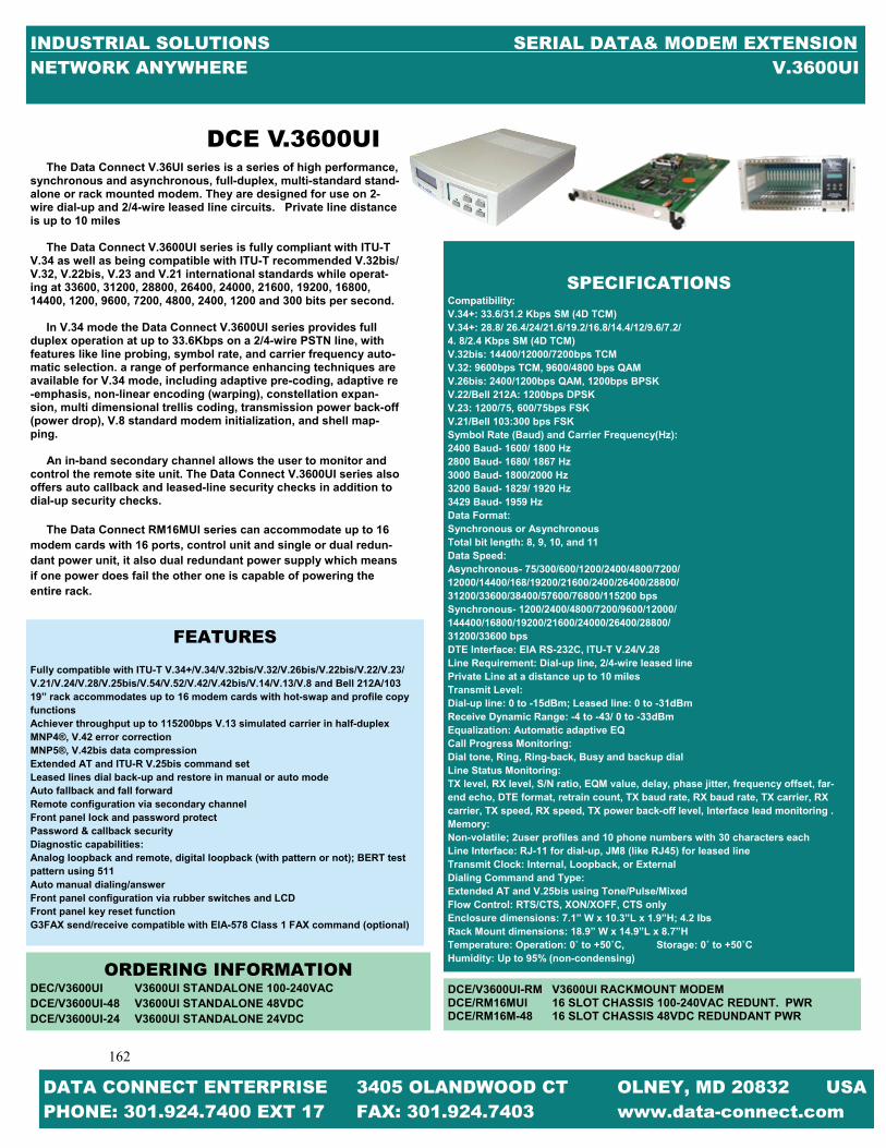
162
162
INDUSTRIAL SOLUTIONS SERIAL DATA& MODEM EXTENSION NETWORK ANYWHERE V.3600UI
DATA CONNECT ENTERPRISE 3405 OLANDWOOD CT OLNEY, MD 20832 USA PHONE: 301.924.7400 EXT 17 FAX: 301.924.7403 www.data-connect.com
The Data Connect V.36UI series is a series of high performance, synchronous and asynchronous, full-duplex, multi-standard stand-alone or rack mounted modem. They are designed for use on 2-wire dial-up and 2/4-wire leased line circuits. Private line distance is up to 10 miles The Data Connect V.3600UI series is fully compliant with ITU-T V.34 as well as being compatible with ITU-T recommended V.32bis/V.32, V.22bis, V.23 and V.21 international standards while operat-ing at 33600, 31200, 28800, 26400, 24000, 21600, 19200, 16800, 14400, 1200, 9600, 7200, 4800, 2400, 1200 and 300 bits per second. In V.34 mode the Data Connect V.3600UI series provides full duplex operation at up to 33.6Kbps on a 2/4-wire PSTN line, with features like line probing, symbol rate, and carrier frequency auto-matic selection. a range of performance enhancing techniques are available for V.34 mode, including adaptive pre-coding, adaptive re-emphasis, non-linear encoding (warping), constellation expan-sion, multi dimensional trellis coding, transmission power back-off (power drop), V.8 standard modem initialization, and shell map-ping. An in-band secondary channel allows the user to monitor and control the remote site unit. The Data Connect V.3600UI series also offers auto callback and leased-line security checks in addition to dial-up security checks. The Data Connect RM16MUI series can accommodate up to 16 modem cards with 16 ports, control unit and single or dual redun-dant power unit, it also dual redundant power supply which means if one power does fail the other one is capable of powering the entire rack.
FEATURES Fully compatible with ITU-T V.34+/V.34/V.32bis/V.32/V.26bis/V.22bis/V.22/V.23/V.21/V.24/V.28/V.25bis/V.54/V.52/V.42/V.42bis/V.14/V.13/V.8 and Bell 212A/103 19” rack accommodates up to 16 modem cards with hot-swap and profile copy functions Achiever throughput up to 115200bps V.13 simulated carrier in half-duplex MNP4®, V.42 error correction MNP5®, V.42bis data compression Extended AT and ITU-R V.25bis command set Leased lines dial back-up and restore in manual or auto mode Auto fallback and fall forward Remote configuration via secondary channel Front panel lock and password protect Password & callback security Diagnostic capabilities: Analog loopback and remote, digital loopback (with pattern or not); BERT test pattern using 511 Auto manual dialing/answer Front panel configuration via rubber switches and LCD Front panel key reset function G3FAX send/receive compatible with EIA-578 Class 1 FAX command (optional)
SPECIFICATIONS
Compatibility: V.34+: 33.6/31.2 Kbps SM (4D TCM) V.34+: 28.8/ 26.4/24/21.6/19.2/16.8/14.4/12/9.6/7.2/ 4. 8/2.4 Kbps SM (4D TCM) V.32bis: 14400/12000/7200bps TCM V.32: 9600bps TCM, 9600/4800 bps QAM V.26bis: 2400/1200bps QAM, 1200bps BPSK V.22/Bell 212A: 1200bps DPSK V.23: 1200/75, 600/75bps FSK V.21/Bell 103:300 bps FSK Symbol Rate (Baud) and Carrier Frequency(Hz): 2400 Baud- 1600/ 1800 Hz 2800 Baud- 1680/ 1867 Hz 3000 Baud- 1800/2000 Hz 3200 Baud- 1829/ 1920 Hz 3429 Baud- 1959 Hz Data Format: Synchronous or Asynchronous Total bit length: 8, 9, 10, and 11 Data Speed: Asynchronous- 75/300/600/1200/2400/4800/7200/ 12000/14400/168/19200/21600/2400/26400/28800/ 31200/33600/38400/57600/76800/115200 bps Synchronous- 1200/2400/4800/7200/9600/12000/ 144400/16800/19200/21600/24000/26400/28800/ 31200/33600 bps DTE Interface: EIA RS-232C, ITU-T V.24/V.28 Line Requirement: Dial-up line, 2/4-wire leased line Private Line at a distance up to 10 miles Transmit Level: Dial-up line: 0 to -15dBm; Leased line: 0 to -31dBm Receive Dynamic Range: -4 to -43/ 0 to -33dBm Equalization: Automatic adaptive EQ Call Progress Monitoring: Dial tone, Ring, Ring-back, Busy and backup dial Line Status Monitoring: TX level, RX level, S/N ratio, EQM value, delay, phase jitter, frequency offset, far-end echo, DTE format, retrain count, TX baud rate, RX baud rate, TX carrier, RX carrier, TX speed, RX speed, TX power back-off level, Interface lead monitoring . Memory: Non-volatile; 2user profiles and 10 phone numbers with 30 characters each Line Interface: RJ-11 for dial-up, JM8 (like RJ45) for leased line Transmit Clock: Internal, Loopback, or External Dialing Command and Type: Extended AT and V.25bis using Tone/Pulse/Mixed Flow Control: RTS/CTS, XON/XOFF, CTS only Enclosure dimensions: 7.1” W x 10.3”L x 1.9”H; 4.2 Ibs Rack Mount dimensions: 18.9” W x 14.9”L x 8.7”H Temperature: Operation: 0˚ to +50˚C, Storage: 0˚ to +50˚C Humidity: Up to 95% (non-condensing)
ORDERING INFORMATION DEC/V3600UI V3600UI STANDALONE 100-240VAC DCE/V3600UI-48 V3600UI STANDALONE 48VDC DCE/V3600UI-24 V3600UI STANDALONE 24VDC
DCE V.3600UI
DCE/V3600UI-RM V3600UI RACKMOUNT MODEM DCE/RM16MUI 16 SLOT CHASSIS 100-240VAC REDUNT. PWR DCE/RM16M-48 16 SLOT CHASSIS 48VDC REDUNDANT PWR

163
163
INDUSTRIAL SOLUTIONS SERIAL DATA& MODEM EXTENSION NETWORK ANYWHERE SWM910A
DATA CONNECT ENTERPRISE 3405 OLANDWOOD CT OLNEY, MD 20832 USA PHONE: 301.924.7400 EXT 17 FAX: 301.924.7403 www.data-connect.com
As industry leaders for extremely robust and reliable license-free data transfer, the Data Connect SS910A provides up to 115kbps serial communications over distances up to 62 miles (100km). Flexible con-figuration options allow for various network topologies. Data Connects proprietary radio technology excels in the most demanding RF and physical environments. The Data Connect SS910A is easily configured through a convenient AT Command Serial Inter-face. Users have the ability to deploy a wide range of network styles including repeaters and multipoint. The master she can diagnose the performance and modify the operating parameters of any remote slave unit. The following are applications for the SS910A. SCADA Telemetry Vehicle Detail Tracking Utilities / Metering Display Signs Traffic Control Many More The SS910A provides a very high Interference and noise rejection allowing reliable communication in high power cellular and paging environments. The repeater units can also act as a slave with no re-strictions on the number of repeaters in the system. Internal CRC and user-selectable forward error correction ensures reliable transmis-sion.
FEATURES Up to 115kbps continuous throughout Extremely Robust Long Range Frequency-Hopping Data Radio Transparent Communications Low Latency adding Little Overhead Supports Point-to-Point, Point-to-Multipoint, Repeater, TDMA Supports TDMA Mode through Units Configured as a Repeater Adjustable Transmit Power (100mW 1W)
SPECIFICATIONS Frequency: 902-928 MHz Spread Method: Frequency Hopping Output Power: 1W User Configurable Sensitivity: -108dBm Data Rate: 1200 to 115.2kbps Uncompressed Range: 62+ miles (100+km) dependent on link rate and line of sight Rejection: 70dB Out of Band, 60dB In Band 50dB Adjacent Channel Operating Modes: Point-to-Point, Point-to-Multipoint, Store & Repeater, TDMA Multi-master Hopping Patterns: 64 User Selectable Diagnostics: Remote Control, Remote Statics, Remote Diagnostics Error Detection: 32bis of CRC with Optional REC Data Interface: Asynchronous RS232 Optional RS422/RS485 RS232 Signals: GRD, TXD, RXD, CTS, RTS, DTR, DRS and DCD Input Voltage: 10-30VDC Power Consumption: 450mA Max at 12V & 1W TX Power 250mA MAX at 12V & 1W TX Power LED Indicators: Power, TX, RX, RSSI Connectors: Antenna: RP-TNC Female Bulkhead Data: RS232 (DB-9F) Locking Screw Connector Environmental: Temperature: -40°C to +85°C Humidity: 5-95% Non-Condensing Weight: 420g Dimensions: 111mm L X 95.3mm W X 44.5mm H Enclosure: Extruded Aluminum Mount: Panel Mount Approvals: FCC Part 15.247 IC RSS210
DCE SWM910A

164
164
INDUSTRIAL SOLUTIONS SERIAL DATA& MODEM EXTENSION NETWORK ANYWHERE DCE SFM
DATA CONNECT ENTERPRISE 3405 OLANDWOOD CT OLNEY, MD 20832 USA PHONE: 301.924.7400 EXT 17 FAX: 301.924.7403 www.data-connect.com
DCE SFM
The Data Connect Serial Fiber Modem Provides a fiber modem solution to extend RS232 or RS485 transmission distance up to 2km over multimode fiber or up to 120km over single mode fiber. The modem is equipped with multiple interface circuits, fro connection to RS232, RS423, or RS485/422 (2 or 4 wire). The DCE SFM secures data transmission over EMI resistant fiber at speeds up to 256kbps for RS232 or up to 1024kbps for RS422/RS485. When the DCE SFM is linked to the DCE SFM-RM card, it allows network engineers to get greater functionality through advanced SNMP features. The network administrator can manage any serial fiber modem module from anywhere on the network and detect any link loss and main-tain each loop.
FEATURES Extend serial transmission from 2 to 120km over fiber Selectable data I/F for RS232/423/422/485/TTL Selectable two or four wire RS485/422 Selectable three to five wire RS232/423 SNMP management features with SFM Chassis Speeds up to 256kbps for RS232 (Async mode)and RS423 Speeds up to 1024kbps for RS485/422 and TTL Support auto-adjustment function, no extra attenuators needed
SPECIFICATIONS
Interfaces: 6 pin screw block connector for RS485/RS232/RS422 serial asynchro-nous ports and SC, ST, or FC 155M fiber ports Operating wavelengths: 1310nm or 1550nm, MM, SM, WDM Operating distance: 2Km on 62.5/125um fiber, up to 120Km on 9/125um fiber Optical Connector: SC, ST or FC available Front LEDs: PWR, Data, Test, Fiber Link Power: External 90-260VAC switching adapter 12VDC@1A with NEMA1-15(2 blades only), US type main plug Temperature: 0-50°C (Operating); 0-70°C (Storage) Humidity: 20-80% non-condensing (Operating); 0-90% (Storage) Consumption: less than 5W Dimension (W x D x H): 85.6mm x 122.6mm x 20mm Weight: 310g (without AC adapter) Compliance: CE, FCC Class A MTBF: 257,063 hours
ORDERING INFORMATION
DCE/SFM FIBER FIBER CONNECTIVITY MODEL TYPE CONNECTOR DISTANCE DCE/SFM-LV S: Single ST 002: 2km DCE/SFM-HV M: Multi SC 015: 15km DCE/SFM-RM W: WDM FC 030: 30km DCE/RM16-SFM 050: 50km 080: 80km 120: 120km *020A: 20km (WDM only) *020B: 20km (WDM only) *040A: 40km (WDM only) *040B: 40km (WDM only) *060A: 60km (WDM only) *060B: 60km (WDM only) *020A must be used with 020B *040A must be used with 040B *060A must be used with 060B

165
165
INDUSTRIAL SOLUTIONS SERIAL DATA& MODEM EXTENSION NETWORK ANYWHERE DCE HS-SFM & SHS-SFM
DATA CONNECT ENTERPRISE 3405 OLANDWOOD CT OLNEY, MD 20832 USA PHONE: 301.924.7400 EXT 17 FAX: 301.924.7403 www.data-connect.com
DCE HS-SFM & SHS-SFM
The Data Connect High Speed Serial Fiber modem is a fiber mo-dem for V.35, RS232, and RS530, X.21 or RS449 high speed (2.048Mbps) synchronous or low speed synchronous and asyn-chronous data transmission over optical fiber media. The Data Connect Super High Speed Serial Fiber Modem is a high speed fiber modem for V.35, RS530, X.21 or RS449 super high-speed (8.192Mbps) synchronous data transmission over optical fiber media. When the DCE HS-SFM-RM or the DCE SHS-SFM-RM is placed in the DCE RM16-F3U rack with SNMP management, the card status, type, version, fiber link status, data link status and alarms can all be displayed. Configuration is also available to enable or disable the port, reset the port, set the data rate, modify the clock mode and initiate local or far end loop back tests.
FEATURES
1 Port data communication on HDB26 female (adapter cable re-quired)
Network management via terminal or SNMP in DCE RM16-F3U chassis
Optical Bit Error Rate less than 10 to the -11 power User selectable n x 64Kbps for the DCE HS-SFM & n x 256Kbps
for DCE SHS-SFM data rate
SPECIFICATIONS STANDARD DESCRIPTION LEDs PWR, Fiber Link, TD, RD, RTS, CTS DCD, Test mode Power AC External AC adapter, 9VDC@1A ACDC 100-240VAC+ or – 10% & 48VDC Environmental Temperature 0 to 50°C (Operating) 0 to 70°C (Storage) Humidity 20 to 80% non Condensing (Operating) 10 to 90% non Condensing (Storage) Power Consumption AC <5W ACDC <5W Dimensions AC 3-3/8 x 4-13/16 x 13/16 inches (D x W x H) ACDC 3-3/8 x 7-9/16 x 1-3/16 inches Weight AC .44 lbs ACDC 1.21 lbs Compliance CE, FCC Class A MTBF 257, 063 Hours
ORDERING INFORMATION
Product Type Copper Fiber Connector Connectivity Interface Type Distance Type DCE/HS-SFM-AC V35 ST 002: 2km DCE/HS-SFM-ACDC RS232 SC 015: 15km DCE/HS-SFM-RM RS530 LC 030: 30km DCE/SHS-SFM-AC X21 050: 50km DCE/SHS-SFM-ACDC RS449 080: 80km DCE/SHS-SFM-RM 120: 120km *020A: 20km [WDM only] *020B: 20km [WDM only] *040A: 40km [WDM only] *040B: 40km [WDM only] *060A: 60km [WDM only] *060B: 60km [WDM only] *020A must be used with 020B *040A must be used with 040B *060A must be used with 060B

166
166
INDUSTRIAL SOLUTIONS INDUSTRIAL SERVERS & SWITCHES NETWORK ANYWHERE CHART
DATA CONNECT ENTERPRISE 3405 OLANDWOOD CT OLNEY, MD 20832 USA PHONE: 301.924.7400 EXT 17 FAX: 301.924.7403 www.data-connect.com
INDUSTRIAL ETHERNET SERIAL SERVERS & SWITCHES CHART
MODEL
ETHERNET SERVER TO
SERIAL DATA
SWITCH 10/100-BASE-T
# OF PORTS
WALL MOUNT
DIN MOUNT
PHOTO PAGE
DCE/EPORT-101 √ √ 1 SERIAL √ √ 168
DCE/EPORT-102 √ √ 2 SERIAL √ √ 168
DCE/EPORT-104 √ √ 4 SERIAL √ √ 169
DCE/ANS205CR √ √ 5
ETHERNET √ 170
DCE/ANS208 √ √ 8
ETHERNET √ 171
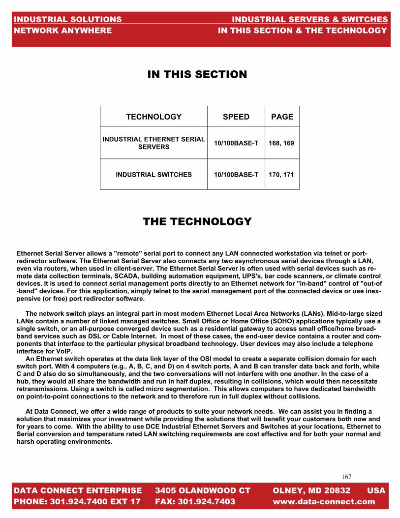
167
167
INDUSTRIAL SOLUTIONS INDUSTRIAL SERVERS & SWITCHES NETWORK ANYWHERE IN THIS SECTION & THE TECHNOLOGY
DATA CONNECT ENTERPRISE 3405 OLANDWOOD CT OLNEY, MD 20832 USA PHONE: 301.924.7400 EXT 17 FAX: 301.924.7403 www.data-connect.com
THE TECHNOLOGY
TECHNOLOGY SPEED PAGE
INDUSTRIAL ETHERNET SERIAL SERVERS
10/100BASE-T 168, 169
INDUSTRIAL SWITCHES 10/100BASE-T 170, 171
IN THIS SECTION
Ethernet Serial Server allows a "remote" serial port to connect any LAN connected workstation via telnet or port-redirector software. The Ethernet Serial Server also connects any two asynchronous serial devices through a LAN, even via routers, when used in client-server. The Ethernet Serial Server is often used with serial devices such as re-mote data collection terminals, SCADA, building automation equipment, UPS's, bar code scanners, or climate control devices. It is used to connect serial management ports directly to an Ethernet network for "in-band" control of "out-of-band" devices. For this application, simply telnet to the serial management port of the connected device or use inex-pensive (or free) port redirector software. The network switch plays an integral part in most modern Ethernet Local Area Networks (LANs). Mid-to-large sized LANs contain a number of linked managed switches. Small Office or Home Office (SOHO) applications typically use a single switch, or an all-purpose converged device such as a residential gateway to access small office/home broad-band services such as DSL or Cable Internet. In most of these cases, the end-user device contains a router and com-ponents that interface to the particular physical broadband technology. User devices may also include a telephone interface for VoIP. An Ethernet switch operates at the data link layer of the OSI model to create a separate collision domain for each switch port. With 4 computers (e.g., A, B, C, and D) on 4 switch ports, A and B can transfer data back and forth, while C and D also do so simultaneously, and the two conversations will not interfere with one another. In the case of a hub, they would all share the bandwidth and run in half duplex, resulting in collisions, which would then necessitate retransmissions. Using a switch is called micro segmentation. This allows computers to have dedicated bandwidth on point-to-point connections to the network and to therefore run in full duplex without collisions. At Data Connect, we offer a wide range of products to suite your network needs. We can assist you in finding a solution that maximizes your investment while providing the solutions that will benefit your customers both now and for years to come. With the ability to use DCE Industrial Ethernet Servers and Switches at your locations, Ethernet to Serial conversion and temperature rated LAN switching requirements are cost effective and for both your normal and harsh operating environments.

168
168
INDUSTRIAL SOLUTIONS INDUSTRIAL SERVERS & SWITCHES NETWORK ANYWHERE EPORT 101 &102
DATA CONNECT ENTERPRISE 3405 OLANDWOOD CT OLNEY, MD 20832 USA PHONE: 301.924.7400 EXT 17 FAX: 301.924.7403 www.data-connect.com
The Data Connect Eport 101/102 Ethernet Serial Server connects RS232, RS422 and RS485 serial devices to an Ethernet LAN/WAN pro-viding a reliable communication connection. The Eport 101/102 Win-dows driver installs virtual COM ports in the Device Manager of the operating system. The virtual COM port is designed to establish a con-nection with the connected serial device in the same manner as a de-vice connected to the COM port in a PC. The LAN becomes transparent to the serial device and the software running on the PC. The Eport 101/102 also offers a heart beat feature to insure reliable communica-tions connection. The Eport 101/102 can be configured as a TCP client/server or UDP. The E-port 101 operates in “Direct IP Mode”, “Virtual COM Mode” and “Paired Mode.” Direct IP connection allows applications using TCP/IP or UDP/IP network socket programs to communicate with asynchro-nous serial port on the Eport 101/102. In this type of application the Eport 101/102 is configured to TCP or UDP server. The socket program running on the PC establishes a communication connection with the Eport 101/102. The raw data is sent directly to and from the serial port. The Virtual COM mode requires the installation of the virtual COM port device driver. In this mode, the Eport101 must be set to either TCP/server or UDP/server in the menu with a designated communication port number. The virtual COM driver is a TCP or UDP client. Once the connection is made, the LAN is transparent to the serial device. Appli-cations work just as if the serial device is connected a host’s physical COM port. The virtual COM port converts the application’s data into IP packet destined for the Eport 101/102, which in turn converts the IP packet back to serial data. Paired mode is also called serial tunneling. When this type of con-figuration is selected, no additional software is needed to install in the host PC. In fact a PC is not required to make the connection. Any to dumb serial devices that can communicate with each other through a serial link will be able to communicate using two Eport101/102s and the LAN. Two Eport 101/102s are configured with one setup as a TCP or UDP client and the other to TCP/UDP server. When setting up the server, the remote IP address section must contain the address of the client. This will allow the client’s IP address to pass the IP address fil-tering features of the server. Conversely, the remote IP address of the client must contain the server address. The Eport 101/102 provides a convenient way to establish reliable communications between two devices. Communication port 5300 is reserved for the Heart beat protocol if a loss connection occurs the heart beat feature will try to reconnect the TCP data connection every 5 seconds until communication is established again. Eport 101/102 will work at Loop Back Mode, all data is sent back immediately. This feature makes connection testing easy.
FEATURES
DIN Rail or Panel Mount Support 10/100Mbps Ethernet Supports RS232, RS422, & RS485 Serial Interface Supports LAN & WAN Communications In Server Mode Supports Individual Client Sessions for
Security Management Access Password Protected Virtual COM drivers for Windows NT/ 98/ME/2000/XP Supports Socket Connection, TCP server, TCP Client, and
UDP Supports up to 2 TCP Connection in TCP Server Mode Heart Beat Connection Guard against Power Failure and
Network description. Supports Loop Back Mode Testing
SPECIFICATIONS
Serial Buffer: Output 64Kbytes- Input 8k bytes per port Serial Connection: DTE-DB9 Male LAN: 10/100 Mbps Auto-Detecting 10 Base T, 100Base TX Serial Interfaces: RS232 TX, RX, RTS, CTS, DTR, DSR, DCD, GND RS422 TX+, TX-, RX+, RX-, RTS+, RTS-, CTS+, CTS-, GND RS485 Data+, Data- and GND Data Rate: 110bps to 230.4kbps Parity: None, Even, Odd, Mark and Space Data Bits: 5, 6, 7, or 8 Stop Bits: 1, 1.5, or 2 Protocol: TCP, IP, ARP, DHCP, Telnet, HTTP, UDP, & ICMP Management: Manager Software, Serial Console, Telnet, Web Server, Firmware upgradeable Dimensions: 8.5cmL x 11.5cmW x 2.3cmH Power Requirements: 9-15VDC, 300mA Operating Temperature: 0˚C to 50˚C Storage Temperature: -20˚C to +60˚C Humidity: 0-90% Non-condensing Approvals: CE, FCC
DCE EPORT 101 & 102

169
169
INDUSTRIAL SOLUTIONS INDUSTRIAL SERVERS & SWITCHES NETWORK ANYWHERE EPORT 104
DATA CONNECT ENTERPRISE 3405 OLANDWOOD CT OLNEY, MD 20832 USA PHONE: 301.924.7400 EXT 17 FAX: 301.924.7403 www.data-connect.com
DCE EPORT 104
The DCE Eport-104 Ethernet serial server connects RS-232, 422, 485 serial devices to an Ethernet LAN/WAN providing a reliable communi-cation connection. The DCE Eport-104 Windows driver installs virtual COM ports in the Device Manager of the operating system. The virtual COM port is designed to establish a connection with the DCE Eport-104. This in turn will allow communications with the connected serial device in the same manner as a device connected to the COM port in a PC. The LAN becomes transparent to the serial device and software running on the PC. The DCE Eport-104 also offers a Heart Beat feature to insure a reliable communications connection. The DCE Eport-104 can be configured as a TPC Client/Server or UDP. The DCE Eport-104 operates in “Direct IP Mode”, “Virtual COM Mode”, and “Paired Mode”. In Direct IP Mode the Direct IP connections allow applications using TCP/IP or UDP/IP network socket programs to communicate with the asynchronous serial port on the DCE Eport-104. In this type of appli-cation the DCE Eport-104 is configured to TCP or UPD server. The socket program running on the PC establishes a communication connection with the DCE Eport-104. The raw data is sent directly to and from the serial port. The Virtual COM mode requires the installation of virtual COM port device driver. In this mode, the DCE Eport-104 must be set to either TCP/server or UPD/server in the menu with designed communication port number.
The virtual COM driver is a TCP or UPD client. Once the connec-tion is made, the LAN is transparent to the serial device. Applications work just as if the serial device is connected a host’s physical COM port. The virtual COM port converts the application’s data into the IP packet back to serial data. Paired mode is also called serial tunneling. When this type of configuration is selected, no additional software is needed to install in a host PC. In fact a PC is not required to make the connection. Any two dumb serial devices that can communicate with each other through a serial link will be able to communicate using the DCE Eport-104 and the LAN.
Two DCE Eport-104s are configured with one setup as a TCP or UDP client and the other to TCP/UPD server. When setting up the Server the Remote IP address section must contain the address of the Client. This will allow the Client’s IP address to pass the IP address-filtering feature of the Server. Conversely, the Remote IP address of the Client must contain the Server’s IP address. In the Heart Beat protocol the DCE Eport-104 provides a conven-ient way to establish reliable communications between two devices. Com-munication port 5300 is reserved for the Heartbeat Protocol. If a loss fea-ture connection occurs the Heart Beat will try to reconnect the TCP data connection every 5 seconds until communication is established again.
FEATURES -Din Rail or panel mount. -Supports 10/100 Mbps Ethernet. -Supports RS-232, RS-422 and RS-485 serial interface. -Supports LAN and WAN communications. -In Server mode supports individual client sessions for security -Management access password protected. -Virtual COM drivers for Windows NT/ 98/ME /2000/XP. -Supports socket connection in TCP server mode. -Heart beat connection ensures reliable TCP connection against power failure or network disruption. - Supports loop back mode. Data is echoed back for easily testing
SPECIFICATIONS
Serial Buffer: Output: 32K bytes Input: 8K bytes per port Serial Connection: DTE—BD-9 male LAN: 10/100 Mbps Auto-detecting – 10 Base T, 100 Base TX Serial Interfaces: RS-232: TX, RX, RTS, CTS, DTR, DSR, DCD, GND RS-422: TX+, TX-, RX+, RX-, CTS+, CTS-, GND RS-485: Data+, Data-, GND Data Rate: 110 bps to 230.4 kbps Parity: none, even, odd, mark, space Data Bits: 5, 6, 7 or 8 Stop Bits: 1, 1.5 or 2 Protocol: TCP, IP, APR, DHCP, Telnet, HTTP, UDP, ICMP Management: Manager Software, Serial Console, Telnet, Web server, Firmware upgradeable Dimensions: Eport-104 – 4.5 x 7.3 x 1.1 in (11.4 x 18.5 x 2.9 cm) Power Requirements: 9 ~15 VDC 500 mA Operating Temperature: 0 to 50°C (32 to 122°F) Storage Temperature: -20 to 60°C (-4 to 140 °F) Humidity: 0—90% Non-Condensing Approvals: CE, FCC
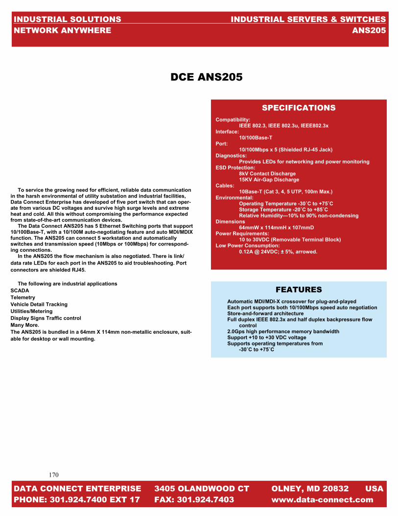
170
170
INDUSTRIAL SOLUTIONS INDUSTRIAL SERVERS & SWITCHES NETWORK ANYWHERE ANS205
DATA CONNECT ENTERPRISE 3405 OLANDWOOD CT OLNEY, MD 20832 USA PHONE: 301.924.7400 EXT 17 FAX: 301.924.7403 www.data-connect.com
To service the growing need for efficient, reliable data communication in the harsh environmental of utility substation and industrial facilities, Data Connect Enterprise has developed of five port switch that can oper-ate from various DC voltages and survive high surge levels and extreme heat and cold. All this without compromising the performance expected from state-of-the-art communication devices. The Data Connect ANS205 has 5 Ethernet Switching ports that support 10/100Base-T, with a 10/100M auto-negotiating feature and auto MDI/MDIX function. The ANS205 can connect 5 workstation and automatically switches and transmission speed (10Mbps or 100Mbps) for correspond-ing connections. In the ANS205 the flow mechanism is also negotiated. There is link/data rate LEDs for each port in the ANS205 to aid troubleshooting. Port connectors are shielded RJ45. The following are industrial applications SCADA Telemetry Vehicle Detail Tracking Utilities/Metering Display Signs Traffic control Many More. The ANS205 is bundled in a 64mm X 114mm non-metallic enclosure, suit-able for desktop or wall mounting.
FEATURES
Automatic MDI/MDI-X crossover for plug-and-played Each port supports both 10/100Mbps speed auto negotiation Store-and-forward architecture Full duplex IEEE 802.3x and half duplex backpressure flow
control 2.0Gps high performance memory bandwidth Support +10 to +30 VDC voltage Supports operating temperatures from
-30˚C to +75˚C
SPECIFICATIONS
Compatibility: IEEE 802.3, IEEE 802.3u, IEEE802.3x Interface: 10/100Base-T Port: 10/100Mbps x 5 (Shielded RJ-45 Jack) Diagnostics: Provides LEDs for networking and power monitoring ESD Protection: 8kV Contact Discharge 15KV Air-Gap Discharge Cables: 10Base-T (Cat 3, 4, 5 UTP, 100m Max.) Environmental: Operating Temperature -30˚C to +75˚C Storage Temperature -20˚C to +85˚C Relative Humidity—10% to 90% non-condensing Dimensions 64mmW x 114mmH x 107mmD Power Requirements: 10 to 30VDC (Removable Terminal Block) Low Power Consumption: 0.12A @ 24VDC; ± 5%, arrowed.
DCE ANS205

171
171
INDUSTRIAL SOLUTIONS INDUSTRIAL SERVERS & SWITCHES NETWORK ANYWHERE ANS 208
DATA CONNECT ENTERPRISE 3405 OLANDWOOD CT OLNEY, MD 20832 USA PHONE: 301.924.7400 EXT 17 FAX: 301.924.7403 www.data-connect.com
To service the growing need for efficient, reliable data communica-tion in the harsh environments of utility substations and industrial facilities, Data Connect Enterprise has developed a five port switch that can operate heat and cold. All this without compromising the performance expected from state-of-the-art communication devices. The Data Connect ANS208 has 8 Ethernet Switching ports that sup-port 10/100Base-T, with a 10/100M auto-negotiation feature and auto MDI/MDIX function. The ANS208 can connect 8 work stations auto-matically switches speed (10Mbps or 200Mbps) for corresponding connections. In the ANS 205 flow control mechanism is also negotiated. There is link/data rate LEDs for each port in the ANS208 to aid troubleshooting. Port Connectors are shielded RJ45. The following are industrial application SCADA Telemetry Vehicle Detail Tracking Utility / Metering Display Signs Traffic Control Many More The ANS208 is bundled in a 64mm x 114mm non-metallic enclo-sure, suitable for desktop or wall mounting.
SPECIFICATIONS
Compatibility: IEEE 802.3, IEEE 802.3u, & IEEE 802.3x Interface: 10/100Base-T Port: 10/100Mbps x 8 (Shield RJ-45 Jack) Diagnostic: Provides LEDs for networking and power monitoring ESD Protection: 8KV Contact discharge 18KV Air-Gap Discharge Cables: 10Base-T (Cat 3, 4, 8 UTP, 100m Max) Environment: Operating Temperature -30˚C to +75˚C Storage Temperature -20˚C to +85˚C Relative Humidity—10% to 90% non-condensing Dimensions: 64mmW x 114mmH x 107mmD Power Requirements: 10 to 30 VDC (Removable Terminal Block) Low Power Consumption: 0.12A @ 24VDC; ± 8%, arrowed
FEATURES
Automatic MDI/MDI-X crossover for plug-and-play Each port Supports both 10/100Mbps speed auto negotiation Store-and-forward architecture Full duplex IEEE 802.3x and half duplex Backpressure flow control 2.0Gps high performance memory bandwidth
DCE ANS208

CATALOG INDEX
172
172 MODEL DESCRIPTION PAGE MODEL DESCRIPTION PAGE
1442E-003-2 14.4Kbps Dial Modem 101 FIBER-E3 E3 Fiber Modem Extension 64
1442E-103-2 14.4Kbps Dial, Leased Line Modem 115 FIBER-T3 T3 Fiber Modem Extension 64
1442E-203-2 14.4Kbps Dial, Leased Line Modem 114 FIBER-TEL Telephone Fiber Extension Mode 60
1442E-503-2 14.4Kbps Dial, Leased Line Modem
117 FIBER-TEL/ Dual Telephone Fiber Modem Extension 60
1442R-003-4 14.4Kbps Rackmount Dial, LL Modem 116 FIBER-TEL/FAX Fax Fiber Modem Extension 60
202TE-037-4 1.2Kbps Leased Line Modem 136, 147 HS-SFM High Speed Serial Fiber Modem 165
202TR-037-4 1.2Kbps Rackmount Leased Line Modem 137 IG144 Industrial Grade 14.4Kbps Dial Modem 102
2178CEE Coax Ethernet Extender 15 IG144S Industrial 14.4Kbps Security Dial Modem 103
2178EE Copper Ethernet Extender 6 IG192HFP Industrial 19.2Kbps Hyper FP Modem 97, 159
2178FEE Fiber Ethernet Extender 16 IG202T Industrial 1.2Kbps Leased Line Modem 130, 141
2178HEE Hardened Ethernet Extender 7 IG202T-R38 Industrial 1.2Kbps Multi-protocol Modem 131, 142
2178HPWEE High Power Wireless Ethernet Extender 19 IG336 Industrial Grade 33.6Kbps Dial Modem 85
2178HSEE High Speed Ethernet Extender 12 IG336S Industrial 33.6Kbps Security Dial Modem 83
2178LRE2/4/8 Long Reach Ethernet Extender 11 IG56 Industrial Grade 56Kbps Dial Modem 75
2178MDEE Multi-drop Ethernet Extender 8 IG56S Industrial 56Kbps Security Dial Modem 76
2178MPEE Multi-point Ethernet Extender 10 IG96HFP Industrial 9.6Kbps Hyper FP Modem 98, 148
2178WEE Wireless Ethernet Extender 17 IGV.23 Industrial 1.2Kbps Leased Line Modem 129, 140
2400E-000-2 2.4Kbps Dial Modem 119 IM56 Industrial 56Kbps Dial Modem 77
2400E-030-4 2.4Kbps Dial, Leased Line Modem 121 IML56 Industrial 56Kbps Leased Line Modem 78
2400E-034-2 2.4Kbps Quick Connect Dial Modem 120 MD14.4 14.4Kbps Rackmount Dial Modem 106
2400E-330-4 2.4Kbps Dial, Leased Line Modem 122 MD14.4L 56Kbps Rackmount Leased Line Modem 111, 156
3342E-004-2 33.6Kbps Dial, Leased Line Modem 86 MD2.4 14.4Kbps Rackmount Dial Modem 125
3342E-208-4 33.6Kbps Dial, Leased Line Modem 88 MD202T 1.2Kbps Rackmount Leased Line Modem 133, 144
3342LP 33.6Kbps Dial, LL Low Profile Modem 84, 161 MD28.8 28.8Kbps Rackmount Dial Modem 93
3342LP+ 33.6Kbps Security Dial Low Profile Modem 82 MD9.6FPD 9.6Kbps Fast Poll Rackmount Modem 151
3342R-004-2 33.6Kbps Rackmount Dial, LL Modem 87 MDR Rackmount Modem Chassis 18 MD slots 107
48V-POEI 48V Power over Ethernet Injector 50 MIU14.4 Industrial 14.4Kbps Dial Modem 104
48V-POEI-12PH 48V Power over Ethernet 12-Port Hub 54 MIU14.4L Industrial 14.4Kbps Leased Line Modem 109, 154
48V-POEI-GB 48V Power over Ethernet GB Injector 51 MIU2.4 Industrial 2.4Kbps Dial Modem 123
48V-POF-GB 48V Power over Fiber GB Injector 55 MIU202T Industrial 1.2Kbps Leased Line Modem 132, 143
5201A-BM 1-Port ADSL2+ Bridge Modem 38 MIU28.8 Industrial 28.8Kbps Leased Line Modem 91
5201A-MR 1-Port ADSL2+ Modem Router 39 MIU9.6FPD Industrial 9.6Kbps Fast Poll Modem 150
5201V-BM 1-Port VDSL2 Bridge Modem 24 MIUPP14.4 14.4Kbps Dial Power thru Serial Interface 105
5204A-GRD 4-Port ADSL2+ Wireless G Router 40 MIUPP14.4L 14.4Kbps LL Power thru Serial Interface 110, 155
5204V-BM 4-Port VDSL2 Bridge Modem 27 MIUPP2.4 2.4Kbps Dial Power thru Serial Interface 124
5204V-MR 4-Port VDSL2 Modem Router 28 MIUPP28.8 28.8Kbps Dial Power thru Serial Interface 92
5204V-NRD 4-Port VDSL2 Wireless N Router 30 MM56 56Kbps OEM PCB Dial Modem 79
5208V-SMS 8-Port VDSL2 CO Switch, 2GB ports 32 PE14.4 14.4Kbps OEM PCB Dial Modem 108
5224A-DSG 24-Port ADSL DSLAM Wireless G 44 PE14.4L 14.4Kbps OEM PCB Leased Line Modem 113
5224V-DSGSFP 24-Port ADSL2+ DSLAM with Fiber 35 PE2.4 2.4Kbps OEM PCB Dial Modem 127
5248A-DSG 48-Port ADSL2+ DSLAM Wireless G 42 PE202T 1.2Kbps OEM PCB Leased Line Modem 135, 146
5248V-DSGSFP 48-Port VDSL DSLAM 1-Fiber Port 35 PE28.8 28.8bps OEM PCB Dial Modem 95
60V-POES 60V POE Surge Suppressor 56 PE9.6FPD 9.6Kbps OEM PCB Fast Poll Modem 153
ANS205CR Industrial 5-Port Switch 170 QUADFIBER-E 4-E1s over Fiber 63
ANS208 Industrial 8-Port Switch 171 QUADFIBER-T 4-T1s over Fiber 63
ATA-1000 Analog Telephone Adapter 52 RM16UI-FIBER Fiber Rackmount Chassis 16 Slots 65
COPPER-T T1 Copper Modem Extender 61 RM20UI-FIBER Fiber Rackmount Chassis 20 Slots 65
D4 Channel Bank 70 RM24UI-FIBER Fiber Rackmount Chassis 24 Slots 65
DSL-FILTER ADSL2+ Filter 46 SFM Serial Fiber Modem 164
DSL-SPLITTER ADSL2+ Splitter 47 SHS-SFM Super High Speed Fiber Modem 165
DSP9612 9.6Kbps Fast Poll Modem 99, 149 SWM910A Serial Wireless Modem Frequency Hop. 165
EPORT-101 Ethernet Serial Server 168 V.3600UI 33.6Kbps Dial, Leased Line LCD Modem 81, 162
EPORT-102 Ethernet Serial Server 168 V3600LP 33.6Kbps Dial, LL Low Profile Modem 84, 161
EPORT-104 Ethernet Serial Server 169 V3600LP+ 33.6Kbps Security Dial Low Profile Modem 82
FIBER -T T-1 Fiber Modem Extension 62

173
173 INDUSTRY & APPLICIATION
Distributors & Consultants Michael Spellerberg 301-924-7400×25 [email protected] Integrators, VARs & Resellers Daniel Rowe 301-924-7400×17 [email protected] Carrier, CLEC, ILEC, ISP Al Dipasquale 973-442-9990 [email protected] International Channel Partners Barry Patton 301-924-7400×12 [email protected] Utility & SCADA Wayne Ware 800-926-0226 [email protected]
MDU/PDU Neal Cennamo 973-442-9990 [email protected] LAN/Network/Demark Extension Bill Patton 610-399-3911 [email protected] Retail/POS Cisco John Shaw 973-442-9990 [email protected] Federal/State Government & Gov-ernment Contractors Lou Costa 301-924-7400×21 [email protected] Small-Medium Business (SMB) Steve Heatter 973-442-9990 [email protected]
TECHNOLOGY SPECIALISTS:
ADSL/VDSL/DSLAM Al Dipasquale 973-442-9990 [email protected] Copper, Ethernet, PoE, Camera Extension Bill Patton 610-399-3911 [email protected] Fiber Extension, PoF, Channel Banks Wayne Ware 800-926-0226 [email protected] Wireless LAN Extension Michael Spellerberg 301-924-7400×25 [email protected] Wireless WAN Extension Daniel Rowe 301-924-7400×17 [email protected]
Telephony, VOIP Steve Heatter 973-442-9990 [email protected] Hosted VOIP, IP Phones Neal Cennamo 973-442-9990 [email protected] Cisco Centric Networks John Shaw 973-442-9990 [email protected] Adtran Centric Networks Lou Costa 301-924-7400×21 [email protected] Legacy Transmission Barry Patton 301-924-7400×12 [email protected]
TECHNICAL SUPPORT:
Michael Spellerberg 301.924.7400 x25 [email protected] Copper, Ethernet, PoE, Camera Extension Fiber Extension, PoF, Channel Banks Wireless LAN & WAN Extension Adtran Centric Networks Legacy Transmission
Steve Heater 973-442-9990 [email protected] ADSL/VDSL/DSLAM Telephony, VOIP Hosted VOIP, IP Phones CISCO Centric Networks

174
174
Data Connect Enterprise, Inc
World Headquarters
3405 Olandwood Court Olney, Maryland 20832
USA 888-4-WAN-LAN (888-492-6526) 301-924-7400
NORTH AMERICA SERVICE/SALES/WAREHOUSE LOCATIONS:
Washington, DC 301-924-7400×17 West Chester, PA 610-399-3911
Wharton, NJ 973-442-9990 Georgetown, TX 800-926-0226
Irvine, CA 888-492-6526
INTERNATIONAL SALES & SERVICE CONTACTS:
Latin America [email protected] (Spanish & English)
[email protected] (Spanish & English)
Asia Pacific [email protected] (Mandarin & English)
Middle East & North Africa (MENA) [email protected]
Central & Western Europe [email protected]
France, Belgium, Monaco, Luxembourg
[email protected] (French & English)
ORDER DCE PRODUCTS ON-LINE:
www.ClickITDirect.com www.DSL-Warehouse.com
DCE AFFILIATE WEBSITES:
Data Connect Enterprise
DCE Express Information Data Products
ARC Electronics Voip-Networking.com
Data Communications Experts Wireless Network Supply
Data Connect US

175
175

176
176