Embed Size (px)
Citation preview
ADS-B GS Test Specifications - Iteration I Document information Project title Surveillance Ground System enhancements for ADS-B
Project N° 15.4.5a Project Manager EUROCONTROL Deliverable Name ADS-B GS Test Specifications - Iteration I Deliverable ID Del 08 Edition 00.01.00
Please complete the advanced properties of the document
Abstract
This Verification Plan addresses the ADS-B 1090 Ground Station Test Specifications within the functional ADS-B Ground Surveillance Domain as defined in task T005, ADS-B GS Test Specifications for iteration 1. It includes the following key information: Scope and context of the ADS-B Ground Station Tests. The Test Specifications applying to the Ground Station for Iteration 1 (derived from
D18, D05 and D07). No particular physical implementation or architecture of the prototypes to be tested is assumed for the Ground Station Tests. This specification will be revisited as appropriate in the course of the project work on iteration 2.
Project ID 15.4.5a D08 - ADS-B GS Test Specifications - Iteration I Edition: 00.01.00
1 of 455
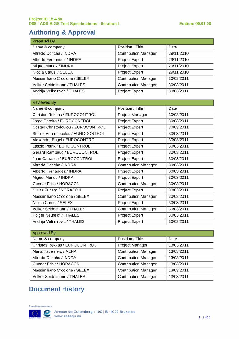
Authoring & Approval Prepared By Name & company Position / Title Date Alfredo Concha / INDRA Contribution Manager 29/11/2010 Alberto Fernandez / INDRA Project Expert 29/11/2010 Miguel Munoz / INDRA Project Expert 29/11/2010 Nicola Carusi / SELEX Project Expert 29/11/2010 Massimiliano Crocione / SELEX Contribution Manager 30/03/2011 Volker Seidelmann / THALES Contribution Manager 30/03/2011 Andrija Velimirovic / THALES Project Expert 30/03/2011
Reviewed By Name & company Position / Title Date Christos Rekkas / EUROCONTROL Project Manager 30/03/2011 Jorge Pereira / EUROCONTROL Project Expert 30/03/2011 Costas Christodoulou / EUROCONTROL Project Expert 30/03/2011 Stelios Adamopoulos / EUROCONTROL Project Expert 30/03/2011 Alexander Engel / EUROCONTROL Project Expert 30/03/2011 Laszlo Petrik / EUROCONTROL Project Expert 30/03/2011 Gerard Rambaud / EUROCONTROL Project Expert 30/03/2011 Juan Carrasco / EUROCONTROL Project Expert 30/03/2011 Alfredo Concha / INDRA Contribution Manager 30/03/2011 Alberto Fernandez / INDRA Project Expert 30/03/2011 Miguel Munoz / INDRA Project Expert 30/03/2011 Gunnar Frisk / NORACON Contribution Manager 30/03/2011 Niklas Friberg / NORACON Project Expert 30/03/2011 Massimiliano Crocione / SELEX Contribution Manager 30/03/2011 Nicola Carusi / SELEX Project Expert 30/03/2011 Volker Seidelmann / THALES Contribution Manager 30/03/2011 Holger Neufeldt / THALES Project Expert 30/03/2011 Andrija Velimirovic / THALES Project Expert 30/03/2011
Approved By Name & company Position / Title Date Christos Rekkas / EUROCONTROL Project Manager 13/03/2011 Maria Tabernero / AENA Contribution Manager 13/03/2011 Alfredo Concha / INDRA Contribution Manager 13/03/2011 Gunnar Frisk / NORACON Contribution Manager 13/03/2011 Massimiliano Crocione / SELEX Contribution Manager 13/03/2011 Volker Seidelmann / THALES Contribution Manager 13/03/2011
Document History
Project ID 15.4.5a D08 - ADS-B GS Test Specifications - Iteration I Edition: 00.01.00
2 of 455
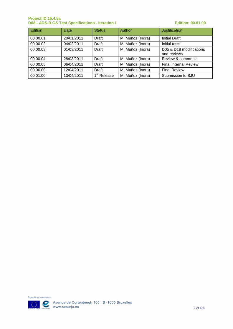
Edition Date Status Author Justification
00.00.01 20/01/2011 Draft M. Muñoz (Indra) Initial Draft 00.00.02 04/02/2011 Draft M. Muñoz (Indra) Initial tests 00.00.03 01/03/2011 Draft M. Muñoz (Indra) D05 & D18 modifications
and reviews 00.00.04 28/03/2011 Draft M. Muñoz (Indra) Review & comments 00.00.05 06/04/2011 Draft M. Muñoz (Indra) Final Internal Review 00.06.00 12/04/2011 Draft M. Muñoz (Indra) Final Review 00.01.00 13/04/2011 1st Release M. Muñoz (Indra) Submission to SJU
Project ID 15.4.5a D08 - ADS-B GS Test Specifications - Iteration I Edition: 00.01.00
3 of 455
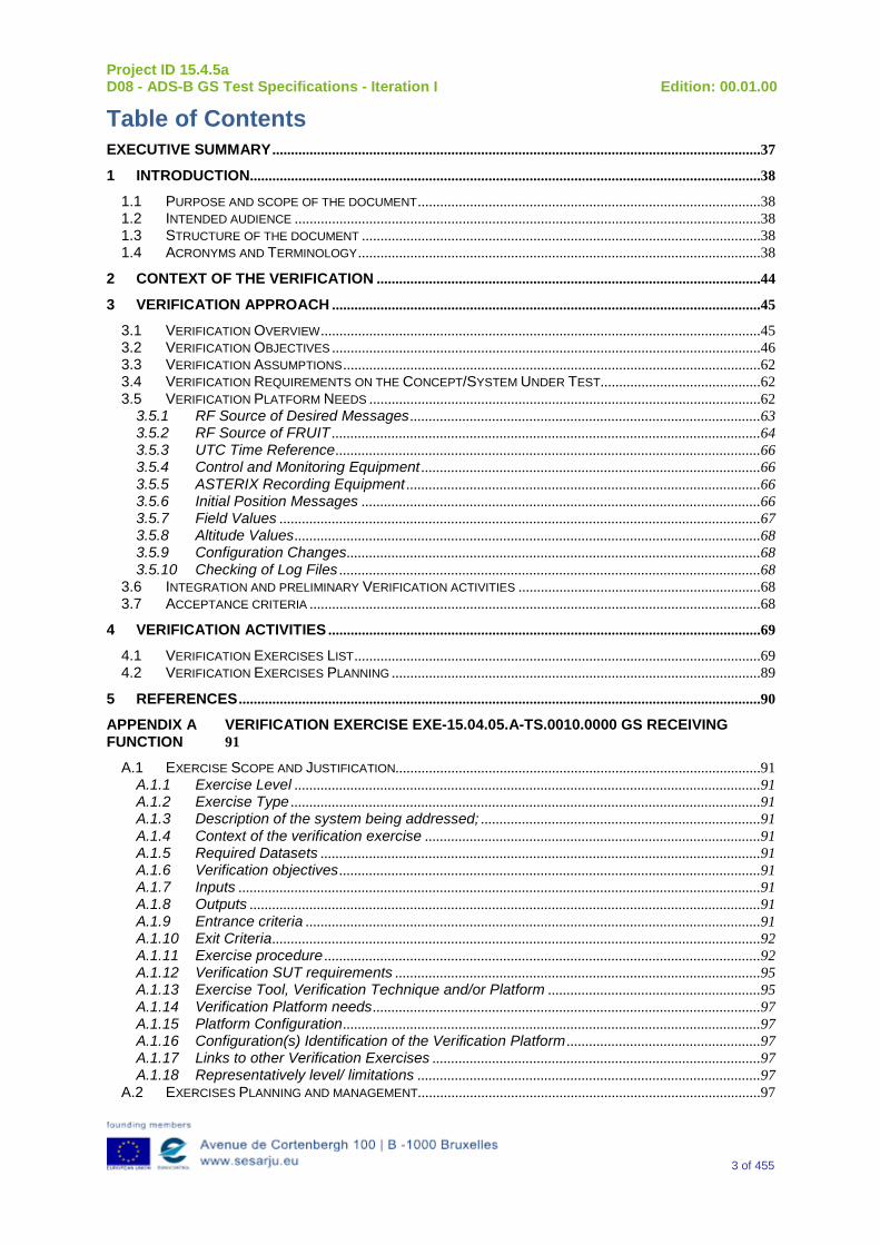
Table of Contents EXECUTIVE SUMMARY ...................................................................................................................................37
1 INTRODUCTION .........................................................................................................................................38 1.1 PURPOSE AND SCOPE OF THE DOCUMENT ............................................................................................38 1.2 INTENDED AUDIENCE .............................................................................................................................38 1.3 STRUCTURE OF THE DOCUMENT ...........................................................................................................38 1.4 ACRONYMS AND TERMINOLOGY ............................................................................................................38
2 CONTEXT OF THE VERIFICATION .......................................................................................................44
3 VERIFICATION APPROACH ...................................................................................................................45 3.1 VERIFICATION OVERVIEW ......................................................................................................................45 3.2 VERIFICATION OBJECTIVES ...................................................................................................................46 3.3 VERIFICATION ASSUMPTIONS ................................................................................................................62 3.4 VERIFICATION REQUIREMENTS ON THE CONCEPT/SYSTEM UNDER TEST ...........................................62 3.5 VERIFICATION PLATFORM NEEDS .........................................................................................................62
3.5.1 RF Source of Desired Messages ..............................................................................................63 3.5.2 RF Source of FRUIT ...................................................................................................................64 3.5.3 UTC Time Reference ..................................................................................................................66 3.5.4 Control and Monitoring Equipment ...........................................................................................66 3.5.5 ASTERIX Recording Equipment ...............................................................................................66 3.5.6 Initial Position Messages ...........................................................................................................66 3.5.7 Field Values .................................................................................................................................67 3.5.8 Altitude Values .............................................................................................................................68 3.5.9 Configuration Changes ...............................................................................................................68 3.5.10 Checking of Log Files .................................................................................................................68
3.6 INTEGRATION AND PRELIMINARY VERIFICATION ACTIVITIES .................................................................68 3.7 ACCEPTANCE CRITERIA .........................................................................................................................68
4 VERIFICATION ACTIVITIES ....................................................................................................................69 4.1 VERIFICATION EXERCISES LIST .............................................................................................................69 4.2 VERIFICATION EXERCISES PLANNING ...................................................................................................89
5 REFERENCES ............................................................................................................................................90 APPENDIX A VERIFICATION EXERCISE EXE-15.04.05.A-TS.0010.0000 GS RECEIVING FUNCTION 91
A.1 EXERCISE SCOPE AND JUSTIFICATION..................................................................................................91 A.1.1 Exercise Level .............................................................................................................................91 A.1.2 Exercise Type ..............................................................................................................................91 A.1.3 Description of the system being addressed; ...........................................................................91 A.1.4 Context of the verification exercise ..........................................................................................91 A.1.5 Required Datasets ......................................................................................................................91 A.1.6 Verification objectives .................................................................................................................91 A.1.7 Inputs ............................................................................................................................................91 A.1.8 Outputs .........................................................................................................................................91 A.1.9 Entrance criteria ..........................................................................................................................91 A.1.10 Exit Criteria ...................................................................................................................................92 A.1.11 Exercise procedure .....................................................................................................................92 A.1.12 Verification SUT requirements ..................................................................................................95 A.1.13 Exercise Tool, Verification Technique and/or Platform .........................................................95 A.1.14 Verification Platform needs ........................................................................................................97 A.1.15 Platform Configuration ................................................................................................................97 A.1.16 Configuration(s) Identification of the Verification Platform ....................................................97 A.1.17 Links to other Verification Exercises ........................................................................................97 A.1.18 Representatively level/ limitations ............................................................................................97
A.2 EXERCISES PLANNING AND MANAGEMENT............................................................................................97
Project ID 15.4.5a D08 - ADS-B GS Test Specifications - Iteration I Edition: 00.01.00
4 of 455
A.2.1 Activities .......................................................................................................................................97 A.2.2 Human Resources. .....................................................................................................................97 A.2.3 Responsibilities in the exercise .................................................................................................97 A.2.4 Training .........................................................................................................................................97 A.2.5 Time planning ..............................................................................................................................97 A.2.6 Risks. ............................................................................................................................................97 A.2.7 Errors and Observation handling ..............................................................................................98
A.3 ANALYSIS SPECIFICATION .....................................................................................................................98 A.3.1 Data collection methods .............................................................................................................98 A.3.2 Analysis method ..........................................................................................................................98 A.3.3 Data logging requirements .........................................................................................................98
APPENDIX B VERIFICATION EXERCISE EXE-15.04.05.A-TS.0010.0010 GS DECODING FUNCTION 99
B.1 EXERCISE SCOPE AND JUSTIFICATION..................................................................................................99 B.1.1 Exercise Level .............................................................................................................................99 B.1.2 Exercise Type ..............................................................................................................................99 B.1.3 Description of the system being addressed; ...........................................................................99 B.1.4 Context of the verification exercise ..........................................................................................99 B.1.5 Required Datasets ......................................................................................................................99 B.1.6 Verification objectives .................................................................................................................99 B.1.7 Inputs ............................................................................................................................................99 B.1.8 Outputs .........................................................................................................................................99 B.1.9 Entrance criteria ..........................................................................................................................99 B.1.10 Exit Criteria .................................................................................................................................100 B.1.11 Exercise procedure ...................................................................................................................100 B.1.12 Verification SUT requirements ................................................................................................103 B.1.13 Exercise Tool, Verification Technique and/or Platform .......................................................103 B.1.14 Verification Platform needs ......................................................................................................104 B.1.15 Platform Configuration ..............................................................................................................104 B.1.16 Configuration(s) Identification of the Verification Platform ..................................................104 B.1.17 Links to other Verification Exercises ......................................................................................104 B.1.18 Representatively level/ limitations ..........................................................................................104
B.2 EXERCISES PLANNING AND MANAGEMENT..........................................................................................104 B.2.1 Activities .....................................................................................................................................104 B.2.2 Human Resources. ...................................................................................................................105 B.2.3 Responsibilities in the exercise ...............................................................................................105 B.2.4 Training .......................................................................................................................................105 B.2.5 Time planning ............................................................................................................................105 B.2.6 Risks. ..........................................................................................................................................105 B.2.7 Errors and Observation handling ............................................................................................105
B.3 ANALYSIS SPECIFICATION ...................................................................................................................105 B.3.1 Data collection methods ...........................................................................................................105 B.3.2 Analysis method ........................................................................................................................105 B.3.3 Data logging requirements .......................................................................................................105
APPENDIX C VERIFICATION EXERCISE EXE-15.04.05.A-TS.0010.0020 GS ASSOCIATION FUNCTION 1 106
C.1 EXERCISE SCOPE AND JUSTIFICATION................................................................................................106 C.1.1 Exercise Level ...........................................................................................................................106 C.1.2 Exercise Type ............................................................................................................................106 C.1.3 Description of the system being addressed; .........................................................................106 C.1.4 Context of the verification exercise ........................................................................................106 C.1.5 Required Datasets ....................................................................................................................106 C.1.6 Verification objectives ...............................................................................................................106 C.1.7 Inputs ..........................................................................................................................................106 C.1.8 Outputs .......................................................................................................................................106 C.1.9 Entrance criteria ........................................................................................................................106
Project ID 15.4.5a D08 - ADS-B GS Test Specifications - Iteration I Edition: 00.01.00
5 of 455
C.1.10 Exit Criteria .................................................................................................................................107 C.1.11 Exercise procedure ...................................................................................................................107 C.1.12 Verification SUT requirements ................................................................................................110 C.1.13 Exercise Tool, Verification Technique and/or Platform .......................................................111 C.1.14 Verification Platform needs ......................................................................................................112 C.1.15 Platform Configuration ..............................................................................................................112 C.1.16 Configuration(s) Identification of the Verification Platform ..................................................112 C.1.17 Links to other Verification Exercises ......................................................................................112 C.1.18 Representatively level/ limitations ..........................................................................................112
C.2 EXERCISES PLANNING AND MANAGEMENT..........................................................................................112 C.2.1 Activities .....................................................................................................................................112 C.2.2 Human Resources. ...................................................................................................................112 C.2.3 Responsibilities in the exercise ...............................................................................................112 C.2.4 Training .......................................................................................................................................112 C.2.5 Time planning ............................................................................................................................112 C.2.6 Risks. ..........................................................................................................................................113 C.2.7 Errors and Observation handling ............................................................................................113
C.3 ANALYSIS SPECIFICATION ...................................................................................................................113 C.3.1 Data collection methods ...........................................................................................................113 C.3.2 Analysis method ........................................................................................................................113 C.3.3 Data logging requirements .......................................................................................................113
APPENDIX D VERIFICATION EXERCISE EXE-15.04.05.A-TS.0010.0030 GS ASSOCIATION FUNCTION 2 114
D.1 EXERCISE SCOPE AND JUSTIFICATION................................................................................................114 D.1.1 Exercise Level ...........................................................................................................................114 D.1.2 Exercise Type ............................................................................................................................114 D.1.3 Description of the system being addressed; .........................................................................114 D.1.4 Context of the verification exercise ........................................................................................114 D.1.5 Required Datasets ....................................................................................................................114 D.1.6 Verification objectives ...............................................................................................................114 D.1.7 Inputs ..........................................................................................................................................114 D.1.8 Outputs .......................................................................................................................................114 D.1.9 Entrance criteria ........................................................................................................................114 D.1.10 Exit Criteria .................................................................................................................................114 D.1.11 Exercise procedure ...................................................................................................................115 D.1.12 Verification SUT requirements ................................................................................................117 D.1.13 Exercise Tool, Verification Technique and/or Platform .......................................................117 D.1.14 Verification Platform needs ......................................................................................................118 D.1.15 Platform Configuration ..............................................................................................................118 D.1.16 Configuration(s) Identification of the Verification Platform ..................................................118 D.1.17 Links to other Verification Exercises ......................................................................................118 D.1.18 Representatively level/ limitations ..........................................................................................118
D.2 EXERCISES PLANNING AND MANAGEMENT..........................................................................................118 D.2.1 Activities .....................................................................................................................................118 D.2.2 Human Resources. ...................................................................................................................119 D.2.3 Responsibilities in the exercise ...............................................................................................119 D.2.4 Training .......................................................................................................................................119 D.2.5 Time planning ............................................................................................................................119 D.2.6 Risks. ..........................................................................................................................................119 D.2.7 Errors and Observation handling ............................................................................................119
D.3 ANALYSIS SPECIFICATION ...................................................................................................................119 D.3.1 Data collection methods ...........................................................................................................119 D.3.2 Analysis method ........................................................................................................................119 D.3.3 Data logging requirements .......................................................................................................119
APPENDIX E VERIFICATION EXERCISE EXE-15.04.05.A-TS.0010.0040 GS VALIDATION 1120 E.1 EXERCISE SCOPE AND JUSTIFICATION................................................................................................120
Project ID 15.4.5a D08 - ADS-B GS Test Specifications - Iteration I Edition: 00.01.00
6 of 455
E.1.1 Exercise Level ...........................................................................................................................120 E.1.2 Exercise Type ............................................................................................................................120 E.1.3 Description of the system being addressed; .........................................................................120 E.1.4 Context of the verification exercise ........................................................................................120 E.1.5 Required Datasets ....................................................................................................................120 E.1.6 Verification objectives ...............................................................................................................120 E.1.7 Inputs ..........................................................................................................................................120 E.1.8 Outputs .......................................................................................................................................120 E.1.9 Entrance criteria ........................................................................................................................121 E.1.10 Exit Criteria .................................................................................................................................121 E.1.11 Exercise procedure ...................................................................................................................121 E.1.12 Verification SUT requirements ................................................................................................123 E.1.13 Exercise Tool, Verification Technique and/or Platform .......................................................123 E.1.14 Verification Platform needs ......................................................................................................124 E.1.15 Platform Configuration ..............................................................................................................124 E.1.16 Configuration(s) Identification of the Verification Platform ..................................................124 E.1.17 Links to other Verification Exercises ......................................................................................124 E.1.18 Representatively level/ limitations ..........................................................................................124
E.2 EXERCISES PLANNING AND MANAGEMENT..........................................................................................125 E.2.1 Activities .....................................................................................................................................125 E.2.2 Human Resources. ...................................................................................................................125 E.2.3 Responsibilities in the exercise ...............................................................................................125 E.2.4 Training .......................................................................................................................................125 E.2.5 Time planning ............................................................................................................................125 E.2.6 Risks. ..........................................................................................................................................125 E.2.7 Errors and Observation handling ............................................................................................125
E.3 ANALYSIS SPECIFICATION ...................................................................................................................125 E.3.1 Data collection methods ...........................................................................................................125 E.3.2 Analysis method ........................................................................................................................125 E.3.3 Data logging requirements .......................................................................................................126
APPENDIX F VERIFICATION EXERCISE EXE-15.04.05.A-TS.0010.0050 GS VALIDATION 2.127 F.1 EXERCISE SCOPE AND JUSTIFICATION................................................................................................127
F.1.1 Exercise Level ...........................................................................................................................127 F.1.2 Exercise Type ............................................................................................................................127 F.1.3 Description of the system being addressed; .........................................................................127 F.1.4 Context of the verification exercise ........................................................................................127 F.1.5 Required Datasets ....................................................................................................................127 F.1.6 Verification objectives ...............................................................................................................127 F.1.7 Inputs ..........................................................................................................................................127 F.1.8 Outputs .......................................................................................................................................127 F.1.9 Entrance criteria ........................................................................................................................128 F.1.10 Exit Criteria .................................................................................................................................128 F.1.11 Exercise procedure ...................................................................................................................128 F.1.12 Verification SUT requirements ................................................................................................131 F.1.13 Exercise Tool, Verification Technique and/or Platform .......................................................132 F.1.14 Verification Platform needs ......................................................................................................133 F.1.15 Platform Configuration ..............................................................................................................133 F.1.16 Configuration(s) Identification of the Verification Platform ..................................................133 F.1.17 Links to other Verification Exercises ......................................................................................133 F.1.18 Representatively level/ limitations ..........................................................................................133
F.2 EXERCISES PLANNING AND MANAGEMENT..........................................................................................133 F.2.1 Activities .....................................................................................................................................133 F.2.2 Human Resources. ...................................................................................................................133 F.2.3 Responsibilities in the exercise ...............................................................................................133 F.2.4 Training .......................................................................................................................................133 F.2.5 Time planning ............................................................................................................................133 F.2.6 Risks. ..........................................................................................................................................134
Project ID 15.4.5a D08 - ADS-B GS Test Specifications - Iteration I Edition: 00.01.00
7 of 455
F.2.7 Errors and Observation handling ............................................................................................134 F.3 ANALYSIS SPECIFICATION ...................................................................................................................134
F.3.1 Data collection methods ...........................................................................................................134 F.3.2 Analysis method ........................................................................................................................134 F.3.3 Data logging requirements .......................................................................................................134
APPENDIX G VERIFICATION EXERCISE EXE-15.04.05.A-TS.0010.0060 GS DATA ITEM INCLUSION 135
G.1 EXERCISE SCOPE AND JUSTIFICATION................................................................................................135 G.1.1 Exercise Level ...........................................................................................................................135 G.1.2 Exercise Type ............................................................................................................................135 G.1.3 Description of the system being addressed; .........................................................................135 G.1.4 Context of the verification exercise ........................................................................................135 G.1.5 Required Datasets ....................................................................................................................135 G.1.6 Verification objectives ...............................................................................................................135 G.1.7 Inputs ..........................................................................................................................................136 G.1.8 Outputs .......................................................................................................................................136 G.1.9 Entrance criteria ........................................................................................................................136 G.1.10 Exit Criteria .................................................................................................................................136 G.1.11 Exercise procedure ...................................................................................................................137 G.1.12 Verification SUT requirements ................................................................................................153 G.1.13 Exercise Tool, Verification Technique and/or Platform .......................................................153 G.1.14 Verification Platform needs ......................................................................................................154 G.1.15 Platform Configuration ..............................................................................................................154 G.1.16 Configuration(s) Identification of the Verification Platform ..................................................154 G.1.17 Links to other Verification Exercises ......................................................................................154 G.1.18 Representatively level/ limitations ..........................................................................................154
G.2 EXERCISES PLANNING AND MANAGEMENT..........................................................................................154 G.2.1 Activities .....................................................................................................................................154 G.2.2 Human Resources. ...................................................................................................................154 G.2.3 Responsibilities in the exercise ...............................................................................................154 G.2.4 Training .......................................................................................................................................155 G.2.5 Time planning ............................................................................................................................155 G.2.6 Risks. ..........................................................................................................................................155 G.2.7 Errors and Observation handling ............................................................................................155
G.3 ANALYSIS SPECIFICATION ...................................................................................................................155 G.3.1 Data collection methods ...........................................................................................................155 G.3.2 Analysis method ........................................................................................................................155 G.3.3 Data logging requirements .......................................................................................................155
APPENDIX H VERIFICATION EXERCISE EXE-15.04.05.A-TS.0020.0000-GS INTEGRITY .......156 H.1 EXERCISE SCOPE AND JUSTIFICATION................................................................................................156
H.1.1 Exercise Level ...........................................................................................................................156 H.1.2 Exercise Type ............................................................................................................................156 H.1.3 Description of the system being addressed; .........................................................................156 H.1.4 Context of the verification exercise ........................................................................................156 H.1.5 Required Datasets ....................................................................................................................156 H.1.6 Verification objectives ...............................................................................................................156 H.1.7 Inputs ..........................................................................................................................................156 H.1.8 Outputs .......................................................................................................................................156 H.1.9 Entrance criteria ........................................................................................................................156 H.1.10 Exit Criteria .................................................................................................................................156 H.1.11 Exercise procedure ...................................................................................................................156 H.1.12 Verification SUT requirements ................................................................................................158 H.1.13 Exercise Tool, Verification Technique and/or Platform .......................................................158 H.1.14 Verification Platform needs ......................................................................................................159 H.1.15 Platform Configuration ..............................................................................................................159 H.1.16 Configuration(s) Identification of the Verification Platform ..................................................159
Project ID 15.4.5a D08 - ADS-B GS Test Specifications - Iteration I Edition: 00.01.00
8 of 455
H.1.17 Links to other Verification Exercises ......................................................................................159 H.1.18 Representatively level/ limitations ..........................................................................................159
H.2 EXERCISES PLANNING AND MANAGEMENT..........................................................................................159 H.2.1 Activities .....................................................................................................................................159 H.2.2 Human Resources. ...................................................................................................................160 H.2.3 Responsibilities in the exercise ...............................................................................................160 H.2.4 Training .......................................................................................................................................160 H.2.5 Time planning ............................................................................................................................160 H.2.6 Risks. ..........................................................................................................................................160 H.2.7 Errors and Observation handling ............................................................................................160
H.3 ANALYSIS SPECIFICATION ...................................................................................................................160 H.3.1 Data collection methods ...........................................................................................................160 H.3.2 Analysis method ........................................................................................................................160 H.3.3 Data logging requirements .......................................................................................................160
APPENDIX I VERIFICATION EXERCISE EXE-15.04.05.A-TS.0020.0010-GS CONTINUITY ........161 I.1 EXERCISE SCOPE AND JUSTIFICATION................................................................................................161
I.1.1 Exercise Level ...............................................................................................................................161 I.1.2 Exercise Type ................................................................................................................................161 I.1.3 Description of the system being addressed; .............................................................................161 I.1.4 Context of the verification exercise ............................................................................................161 I.1.5 Required Datasets ........................................................................................................................161 I.1.6 Verification objectives ...................................................................................................................161 I.1.7 Inputs ..............................................................................................................................................161 I.1.8 Outputs ...........................................................................................................................................161 I.1.9 Entrance criteria ............................................................................................................................161 I.1.10 Exit Criteria .................................................................................................................................161 I.1.11 Exercise procedure ...................................................................................................................162 I.1.12 Verification SUT requirements ................................................................................................162 I.1.13 Exercise Tool, Verification Technique and/or Platform .......................................................163 I.1.14 Verification Platform needs ......................................................................................................163 I.1.15 Platform Configuration ..............................................................................................................163 I.1.16 Configuration(s) Identification of the Verification Platform ..................................................163 I.1.17 Links to other Verification Exercises ......................................................................................163 I.1.18 Representatively level/ limitations ..........................................................................................163
I.2 EXERCISES PLANNING AND MANAGEMENT..........................................................................................163 I.2.1 Activities .........................................................................................................................................163 I.2.2 Human Resources. .......................................................................................................................163 I.2.3 Responsibilities in the exercise ...................................................................................................163 I.2.4 Training ...........................................................................................................................................163 I.2.5 Time planning ................................................................................................................................163 I.2.6 Risks. ..............................................................................................................................................164 I.2.7 Errors and Observation handling ................................................................................................164
I.3 ANALYSIS SPECIFICATION ...................................................................................................................164 I.3.1 Data collection methods ...............................................................................................................164 I.3.2 Analysis method ............................................................................................................................164 I.3.3 Data logging requirements ...........................................................................................................164
APPENDIX J VERIFICATION EXERCISE EXE-15.04.05.A-TS.0020.0020-GS LATENCY ........165 J.1 EXERCISE SCOPE AND JUSTIFICATION................................................................................................165
J.1.1 Exercise Level ...........................................................................................................................165 J.1.2 Exercise Type ............................................................................................................................165 J.1.3 Description of the system being addressed; .........................................................................165 J.1.4 Context of the verification exercise ........................................................................................165 J.1.5 Required Datasets ....................................................................................................................165 J.1.6 Verification objectives ...............................................................................................................165 J.1.7 Inputs ..........................................................................................................................................165 J.1.8 Outputs .......................................................................................................................................165
Project ID 15.4.5a D08 - ADS-B GS Test Specifications - Iteration I Edition: 00.01.00
9 of 455
J.1.9 Entrance criteria ........................................................................................................................165 J.1.10 Exit Criteria .................................................................................................................................166 J.1.11 Exercise procedure ...................................................................................................................166 J.1.12 Verification SUT requirements ................................................................................................167 J.1.13 Exercise Tool, Verification Technique and/or Platform .......................................................167 J.1.14 Verification Platform needs ......................................................................................................168 J.1.15 Platform Configuration ..............................................................................................................168 J.1.16 Configuration(s) Identification of the Verification Platform ..................................................168 J.1.17 Links to other Verification Exercises ......................................................................................168 J.1.18 Representatively level/ limitations ..........................................................................................168
J.2 EXERCISES PLANNING AND MANAGEMENT..........................................................................................168 J.2.1 Activities .....................................................................................................................................168 J.2.2 Human Resources. ...................................................................................................................169 J.2.3 Responsibilities in the exercise ...............................................................................................169 J.2.4 Training .......................................................................................................................................169 J.2.5 Time planning ............................................................................................................................169 J.2.6 Risks. ..........................................................................................................................................169 J.2.7 Errors and Observation handling ............................................................................................169
J.3 ANALYSIS SPECIFICATION ...................................................................................................................169 J.3.1 Data collection methods ...........................................................................................................169 J.3.2 Analysis method ........................................................................................................................169 J.3.3 Data logging requirements .......................................................................................................169
APPENDIX K VERIFICATION EXERCISE EXE-15.04.05.A-TS.0020.0030-GS TOA ACCURACY 170
K.1 EXERCISE SCOPE AND JUSTIFICATION................................................................................................170 K.1.1 Exercise Level ...........................................................................................................................170 K.1.2 Exercise Type ............................................................................................................................170 K.1.3 Description of the system being addressed; .........................................................................170 K.1.4 Context of the verification exercise ........................................................................................170 K.1.5 Required Datasets ....................................................................................................................170 K.1.6 Verification objectives ...............................................................................................................170 K.1.7 Inputs ..........................................................................................................................................170 K.1.8 Outputs .......................................................................................................................................170 K.1.9 Entrance criteria ........................................................................................................................170 K.1.10 Exit Criteria .................................................................................................................................170 K.1.11 Exercise procedure ...................................................................................................................171 K.1.12 Verification SUT requirements ................................................................................................171 K.1.13 Exercise Tool, Verification Technique and/or Platform .......................................................171 K.1.14 Verification Platform needs ......................................................................................................171 K.1.15 Platform Configuration ..............................................................................................................171 K.1.16 Configuration(s) Identification of the Verification Platform ..................................................171 K.1.17 Links to other Verification Exercises ......................................................................................171 K.1.18 Representatively level/ limitations ..........................................................................................171
K.2 EXERCISES PLANNING AND MANAGEMENT..........................................................................................172 K.2.1 Activities .....................................................................................................................................172 K.2.2 Human Resources. ...................................................................................................................172 K.2.3 Responsibilities in the exercise ...............................................................................................172 K.2.4 Training .......................................................................................................................................172 K.2.5 Time planning ............................................................................................................................172 K.2.6 Risks. ..........................................................................................................................................172 K.2.7 Errors and Observation handling ............................................................................................172
K.3 ANALYSIS SPECIFICATION ...................................................................................................................172 K.3.1 Data collection methods ...........................................................................................................172 K.3.2 Analysis method ........................................................................................................................172 K.3.3 Data logging requirements .......................................................................................................172
APPENDIX L VERIFICATION EXERCISE EXE-15.04.05.A-TS.0020.0040-GS CAPACITY ........173
Project ID 15.4.5a D08 - ADS-B GS Test Specifications - Iteration I Edition: 00.01.00
10 of 455
L.1 EXERCISE SCOPE AND JUSTIFICATION................................................................................................173 L.1.1 Exercise Level ...........................................................................................................................173 L.1.2 Exercise Type ............................................................................................................................173 L.1.3 Description of the system being addressed; .........................................................................173 L.1.4 Context of the verification exercise ........................................................................................173 L.1.5 Required Datasets ....................................................................................................................173 L.1.6 Verification objectives ...............................................................................................................173 L.1.7 Inputs ..........................................................................................................................................173 L.1.8 Outputs .......................................................................................................................................173 L.1.9 Entrance criteria ........................................................................................................................173 L.1.10 Exit Criteria .................................................................................................................................173 L.1.11 Exercise procedure ...................................................................................................................174 L.1.12 Verification SUT requirements ................................................................................................175 L.1.13 Exercise Tool, Verification Technique and/or Platform .......................................................176 L.1.14 Verification Platform needs ......................................................................................................177 L.1.15 Platform Configuration ..............................................................................................................177 L.1.16 Configuration(s) Identification of the Verification Platform ..................................................177 L.1.17 Links to other Verification Exercises ......................................................................................177 L.1.18 Representatively level/ limitations ..........................................................................................177
L.2 EXERCISES PLANNING AND MANAGEMENT..........................................................................................177 L.2.1 Activities .....................................................................................................................................177 L.2.2 Human Resources. ...................................................................................................................177 L.2.3 Responsibilities in the exercise ...............................................................................................177 L.2.4 Training .......................................................................................................................................177 L.2.5 Time planning ............................................................................................................................177 L.2.6 Risks. ..........................................................................................................................................178 L.2.7 Errors and Observation handling ............................................................................................178
L.3 ANALYSIS SPECIFICATION ...................................................................................................................178 L.3.1 Data collection methods ...........................................................................................................178 L.3.2 Analysis method ........................................................................................................................178 L.3.3 Data logging requirements .......................................................................................................178
APPENDIX M VERIFICATION EXERCISE EXE-15.04.05.A-TS.0020.0050-GS DUPLICATED 24BIT ADDRESSES ........................................................................................................................................179
M.1 EXERCISE SCOPE AND JUSTIFICATION................................................................................................179 M.1.1 Exercise Level ...........................................................................................................................179 M.1.2 Exercise Type ............................................................................................................................179 M.1.3 Description of the system being addressed; .........................................................................179 M.1.4 Context of the verification exercise ........................................................................................179 M.1.5 Required Datasets ....................................................................................................................179 M.1.6 Verification objectives ...............................................................................................................179 M.1.7 Inputs ..........................................................................................................................................179 M.1.8 Outputs .......................................................................................................................................179 M.1.9 Entrance criteria ........................................................................................................................180 M.1.10 Exit Criteria .................................................................................................................................180 M.1.11 Exercise procedure ...................................................................................................................180 M.1.12 Verification SUT requirements ................................................................................................184 M.1.13 Exercise Tool, Verification Technique and/or Platform .......................................................185 M.1.14 Verification Platform needs ......................................................................................................185 M.1.15 Platform Configuration ..............................................................................................................186 M.1.16 Configuration(s) Identification of the Verification Platform ..................................................186 M.1.17 Links to other Verification Exercises ......................................................................................186 M.1.18 Representatively level/ limitations ..........................................................................................186
M.2 EXERCISES PLANNING AND MANAGEMENT..........................................................................................186 M.2.1 Activities .....................................................................................................................................186 M.2.2 Human Resources. ...................................................................................................................186 M.2.3 Responsibilities in the exercise ...............................................................................................186 M.2.4 Training .......................................................................................................................................186
Project ID 15.4.5a D08 - ADS-B GS Test Specifications - Iteration I Edition: 00.01.00
11 of 455
M.2.5 Time planning ............................................................................................................................186 M.2.6 Risks. ..........................................................................................................................................186 M.2.7 Errors and Observation handling ............................................................................................187
M.3 ANALYSIS SPECIFICATION ...................................................................................................................187 M.3.1 Data collection methods ...........................................................................................................187 M.3.2 Analysis method ........................................................................................................................187 M.3.3 Data logging requirements .......................................................................................................187
APPENDIX N VERIFICATION EXERCISE EXE-15.04.05.A-TS.0020.0060-GS REPORT PROBABILITY FOR TARGET IN EN-ROUTE AIRSPACE .......................................................................188
N.1 EXERCISE SCOPE AND JUSTIFICATION................................................................................................188 N.1.1 Exercise Level ...........................................................................................................................188 N.1.2 Exercise Type ............................................................................................................................188 N.1.3 Description of the system being addressed; .........................................................................188 N.1.4 Context of the verification exercise ........................................................................................188 N.1.5 Required Datasets ....................................................................................................................188 N.1.6 Verification objectives ...............................................................................................................188 N.1.7 Inputs ..........................................................................................................................................188 N.1.8 Outputs .......................................................................................................................................188 N.1.9 Entrance criteria ........................................................................................................................189 N.1.10 Exit Criteria .................................................................................................................................189 N.1.11 Exercise procedure ...................................................................................................................189 N.1.12 Verification SUT requirements ................................................................................................191 N.1.13 Exercise Tool, Verification Technique and/or Platform .......................................................192 N.1.14 Verification Platform needs ......................................................................................................192 N.1.15 Platform Configuration ..............................................................................................................192 N.1.16 Configuration(s) Identification of the Verification Platform ..................................................193 N.1.17 Links to other Verification Exercises ......................................................................................193 N.1.18 Representatively level/ limitations ..........................................................................................193
N.2 EXERCISES PLANNING AND MANAGEMENT..........................................................................................193 N.2.1 Activities .....................................................................................................................................193 N.2.2 Human Resources. ...................................................................................................................193 N.2.3 Responsibilities in the exercise ...............................................................................................193 N.2.4 Training .......................................................................................................................................193 N.2.5 Time planning ............................................................................................................................193 N.2.6 Risks. ..........................................................................................................................................193 N.2.7 Errors and Observation handling ............................................................................................193
N.3 ANALYSIS SPECIFICATION ...................................................................................................................194 N.3.1 Data collection methods ...........................................................................................................194 N.3.2 Analysis method ........................................................................................................................194 N.3.3 Data logging requirements .......................................................................................................194
APPENDIX O VERIFICATION EXERCISE EXE-15.04.05.A-TS.0020.0070-GS CHANGE OF MODE A CODE EN ROUTE ...........................................................................................................................195
O.1 EXERCISE SCOPE AND JUSTIFICATION................................................................................................195 O.1.1 Exercise Level ...........................................................................................................................195 O.1.2 Exercise Type ............................................................................................................................195 O.1.3 Description of the system being addressed; .........................................................................195 O.1.4 Context of the verification exercise ........................................................................................195 O.1.5 Required Datasets ....................................................................................................................195 O.1.6 Verification objectives ...............................................................................................................195 O.1.7 Inputs ..........................................................................................................................................195 O.1.8 Outputs .......................................................................................................................................195 O.1.9 Entrance criteria ........................................................................................................................195 O.1.10 Exit Criteria .................................................................................................................................195 O.1.11 Exercise procedure ...................................................................................................................196 O.1.12 Verification SUT requirements ................................................................................................198 O.1.13 Exercise Tool, Verification Technique and/or Platform .......................................................199
Project ID 15.4.5a D08 - ADS-B GS Test Specifications - Iteration I Edition: 00.01.00
12 of 455
O.1.14 Verification Platform needs ......................................................................................................199 O.1.15 Platform Configuration ..............................................................................................................200 O.1.16 Configuration(s) Identification of the Verification Platform ..................................................200 O.1.17 Links to other Verification Exercises ......................................................................................200 O.1.18 Representatively level/ limitations ..........................................................................................200
O.2 EXERCISES PLANNING AND MANAGEMENT..........................................................................................200 O.2.1 Activities .....................................................................................................................................200 O.2.2 Human Resources. ...................................................................................................................200 O.2.3 Responsibilities in the exercise ...............................................................................................200 O.2.4 Training .......................................................................................................................................200 O.2.5 Time planning ............................................................................................................................200 O.2.6 Risks. ..........................................................................................................................................200 O.2.7 Errors and Observation handling ............................................................................................200
O.3 ANALYSIS SPECIFICATION ...................................................................................................................201 O.3.1 Data collection methods ...........................................................................................................201 O.3.2 Analysis method ........................................................................................................................201 O.3.3 Data logging requirements .......................................................................................................201
APPENDIX P VERIFICATION EXERCISE EXE-15.04.05.A-TS.0020.0080-GS CHANGE OF EMERGENCY AND SPI INFORMATION DETECTION PROBABILITY FOR TARGET IN EN-ROUTE AIRSPACE 202
P.1 EXERCISE SCOPE AND JUSTIFICATION................................................................................................202 P.1.1 Exercise Level ...........................................................................................................................202 P.1.2 Exercise Type ............................................................................................................................202 P.1.3 Description of the system being addressed; .........................................................................202 P.1.4 Context of the verification exercise ........................................................................................202 P.1.5 Required Datasets ....................................................................................................................202 P.1.6 Verification objectives ...............................................................................................................202 P.1.7 Inputs ..........................................................................................................................................202 P.1.8 Outputs .......................................................................................................................................202 P.1.9 Entrance criteria ........................................................................................................................202 P.1.10 Exit Criteria .................................................................................................................................203 P.1.11 Exercise procedure ...................................................................................................................203 P.1.12 Verification SUT requirements ................................................................................................206 P.1.13 Exercise Tool, Verification Technique and/or Platform .......................................................206 P.1.14 Verification Platform needs ......................................................................................................207 P.1.15 Platform Configuration ..............................................................................................................207 P.1.16 Configuration(s) Identification of the Verification Platform ..................................................207 P.1.17 Links to other Verification Exercises ......................................................................................207 P.1.18 Representatively level/ limitations ..........................................................................................207
P.2 EXERCISES PLANNING AND MANAGEMENT..........................................................................................207 P.2.1 Activities .....................................................................................................................................207 P.2.2 Human Resources. ...................................................................................................................207 P.2.3 Responsibilities in the exercise ...............................................................................................207 P.2.4 Training .......................................................................................................................................207 P.2.5 Time planning ............................................................................................................................208 P.2.6 Risks. ..........................................................................................................................................208 P.2.7 Errors and Observation handling ............................................................................................208
P.3 ANALYSIS SPECIFICATION ...................................................................................................................208 P.3.1 Data collection methods ...........................................................................................................208 P.3.2 Analysis method ........................................................................................................................208 P.3.3 Data logging requirements .......................................................................................................208
APPENDIX Q VERIFICATION EXERCISE EXE-15.04.05.A-TS.0020.0090-GS REPORT PROBABILITY FOR TARGET IN TMA AIRSPACE ...................................................................................209
Q.1 EXERCISE SCOPE AND JUSTIFICATION................................................................................................209 Q.1.1 Exercise Level ...........................................................................................................................209 Q.1.2 Exercise Type ............................................................................................................................209
Project ID 15.4.5a D08 - ADS-B GS Test Specifications - Iteration I Edition: 00.01.00
13 of 455
Q.1.3 Description of the system being addressed; .........................................................................209 Q.1.4 Context of the verification exercise ........................................................................................209 Q.1.5 Required Datasets ....................................................................................................................209 Q.1.6 Verification objectives ...............................................................................................................209 Q.1.7 Inputs ..........................................................................................................................................209 Q.1.8 Outputs .......................................................................................................................................210 Q.1.9 Entrance criteria ........................................................................................................................210 Q.1.10 Exit Criteria .................................................................................................................................210 Q.1.11 Exercise procedure ...................................................................................................................210 Q.1.12 Verification SUT requirements ................................................................................................212 Q.1.13 Exercise Tool, Verification Technique and/or Platform .......................................................213 Q.1.14 Verification Platform needs ......................................................................................................213 Q.1.15 Platform Configuration ..............................................................................................................214 Q.1.16 Configuration(s) Identification of the Verification Platform ..................................................214 Q.1.17 Links to other Verification Exercises ......................................................................................214 Q.1.18 Representatively level/ limitations ..........................................................................................214
Q.2 EXERCISES PLANNING AND MANAGEMENT..........................................................................................214 Q.2.1 Activities .....................................................................................................................................214 Q.2.2 Human Resources. ...................................................................................................................214 Q.2.3 Responsibilities in the exercise ...............................................................................................214 Q.2.4 Training .......................................................................................................................................214 Q.2.5 Time planning ............................................................................................................................214 Q.2.6 Risks. ..........................................................................................................................................214 Q.2.7 Errors and Observation handling ............................................................................................214
Q.3 ANALYSIS SPECIFICATION ...................................................................................................................215 Q.3.1 Data collection methods ...........................................................................................................215 Q.3.2 Analysis method ........................................................................................................................215 Q.3.3 Data logging requirements .......................................................................................................215
APPENDIX R VERIFICATION EXERCISE EXE-15.04.05.A-TS.0020.0100-GS CHANGE OF MODE A CODE TMA .......................................................................................................................................216
R.1 EXERCISE SCOPE AND JUSTIFICATION................................................................................................216 R.1.1 Exercise Level ...........................................................................................................................216 R.1.2 Exercise Type ............................................................................................................................216 R.1.3 Description of the system being addressed; .........................................................................216 R.1.4 Context of the verification exercise ........................................................................................216 R.1.5 Required Datasets ....................................................................................................................216 R.1.6 Verification objectives ...............................................................................................................216 R.1.7 Inputs ..........................................................................................................................................216 R.1.8 Outputs .......................................................................................................................................216 R.1.9 Entrance criteria ........................................................................................................................216 R.1.10 Exit Criteria .................................................................................................................................216 R.1.11 Exercise procedure ...................................................................................................................217 R.1.12 Verification SUT requirements ................................................................................................220 R.1.13 Exercise Tool, Verification Technique and/or Platform .......................................................220 R.1.14 Verification Platform needs ......................................................................................................221 R.1.15 Platform Configuration ..............................................................................................................221 R.1.16 Configuration(s) Identification of the Verification Platform ..................................................221 R.1.17 Links to other Verification Exercises ......................................................................................221 R.1.18 Representatively level/ limitations ..........................................................................................221
R.2 EXERCISES PLANNING AND MANAGEMENT..........................................................................................221 R.2.1 Activities .....................................................................................................................................221 R.2.2 Human Resources. ...................................................................................................................221 R.2.3 Responsibilities in the exercise ...............................................................................................221 R.2.4 Training .......................................................................................................................................221 R.2.5 Time planning ............................................................................................................................221 R.2.6 Risks. ..........................................................................................................................................221 R.2.7 Errors and Observation handling ............................................................................................222
Project ID 15.4.5a D08 - ADS-B GS Test Specifications - Iteration I Edition: 00.01.00
14 of 455
R.3 ANALYSIS SPECIFICATION ...................................................................................................................222 R.3.1 Data collection methods ...........................................................................................................222 R.3.2 Analysis method ........................................................................................................................222 R.3.3 Data logging requirements .......................................................................................................222
APPENDIX S VERIFICATION EXERCISE EXE-15.04.05.A-TS.0020.0110-GS CHANGE OF EMERGENCY SPI INFORMATION TMA .....................................................................................................223
S.1 EXERCISE SCOPE AND JUSTIFICATION................................................................................................223 S.1.1 Exercise Level ...........................................................................................................................223 S.1.2 Exercise Type ............................................................................................................................223 S.1.3 Description of the system being addressed; .........................................................................223 S.1.4 Context of the verification exercise ........................................................................................223 S.1.5 Required Datasets ....................................................................................................................223 S.1.6 Verification objectives ...............................................................................................................223 S.1.7 Inputs ..........................................................................................................................................223 S.1.8 Outputs .......................................................................................................................................223 S.1.9 Entrance criteria ........................................................................................................................223 S.1.10 Exit Criteria .................................................................................................................................223 S.1.11 Exercise procedure ...................................................................................................................224 S.1.12 Verification SUT requirements ................................................................................................227 S.1.13 Exercise Tool, Verification Technique and/or Platform .......................................................227 S.1.14 Verification Platform needs ......................................................................................................228 S.1.15 Platform Configuration ..............................................................................................................228 S.1.16 Configuration(s) Identification of the Verification Platform ..................................................228 S.1.17 Links to other Verification Exercises ......................................................................................228 S.1.18 Representatively level/ limitations ..........................................................................................228
S.2 EXERCISES PLANNING AND MANAGEMENT..........................................................................................228 S.2.1 Activities .....................................................................................................................................228 S.2.2 Human Resources. ...................................................................................................................228 S.2.3 Responsibilities in the exercise ...............................................................................................228 S.2.4 Training .......................................................................................................................................228 S.2.5 Time planning ............................................................................................................................229 S.2.6 Risks. ..........................................................................................................................................229 S.2.7 Errors and Observation handling ............................................................................................229
S.3 ANALYSIS SPECIFICATION ...................................................................................................................229 S.3.1 Data collection methods ...........................................................................................................229 S.3.2 Analysis method ........................................................................................................................229 S.3.3 Data logging requirements .......................................................................................................229
APPENDIX T VERIFICATION EXERCISE EXE-15.04.05.A-TS.0030.0 10-GS INTEGRATION WITH WAM 230
T.1 EXERCISE SCOPE AND JUSTIFICATION................................................................................................230 T.1.1 Exercise Level ...........................................................................................................................230 T.1.2 Exercise Type ............................................................................................................................230 T.1.3 Description of the system being addressed; .........................................................................230 T.1.4 Context of the verification exercise ........................................................................................230 T.1.5 Required Datasets ....................................................................................................................230 T.1.6 Verification objectives ...............................................................................................................230 T.1.7 Inputs ..........................................................................................................................................231 T.1.8 Outputs .......................................................................................................................................231 T.1.9 Entrance criteria ........................................................................................................................231 T.1.10 Exit Criteria .................................................................................................................................231 T.1.11 Exercise procedure ...................................................................................................................231 T.1.12 Verification SUT requirements ................................................................................................234 T.1.13 Exercise Tool, Verification Technique and/or Platform .......................................................235 T.1.14 Verification Platform needs ......................................................................................................236 T.1.15 Platform Configuration ..............................................................................................................236 T.1.16 Configuration(s) Identification of the Verification Platform ..................................................236
Project ID 15.4.5a D08 - ADS-B GS Test Specifications - Iteration I Edition: 00.01.00
15 of 455
T.1.17 Links to other Verification Exercises ......................................................................................236 T.1.18 Representatively level/ limitations ..........................................................................................236
T.2 EXERCISES PLANNING AND MANAGEMENT..........................................................................................236 T.2.1 Activities .....................................................................................................................................236 T.2.2 Human Resources. ...................................................................................................................236 T.2.3 Responsibilities in the exercise ...............................................................................................236 T.2.4 Training .......................................................................................................................................236 T.2.5 Time planning ............................................................................................................................236 T.2.6 Risks. ..........................................................................................................................................236 T.2.7 Errors and Observation handling ............................................................................................237
T.3 ANALYSIS SPECIFICATION ...................................................................................................................237 T.3.1 Data collection methods ...........................................................................................................237 T.3.2 Analysis method ........................................................................................................................237 T.3.3 Data logging requirements .......................................................................................................237
APPENDIX U VERIFICATION EXERCISE EXE-15.04.05.A-TS.0040.0000 GS ANGLE OF ARRIVAL VALIDATION ..................................................................................................................................238
U.1 EXERCISE SCOPE AND JUSTIFICATION................................................................................................238 U.1.1 Exercise Level ...........................................................................................................................238 U.1.2 Exercise Type ............................................................................................................................238 U.1.3 Description of the system being addressed; .........................................................................238 U.1.4 Context of the verification exercise ........................................................................................238 U.1.5 Required Datasets ....................................................................................................................238 U.1.6 Verification objectives ...............................................................................................................238 U.1.7 Inputs ..........................................................................................................................................239 U.1.8 Outputs .......................................................................................................................................239 U.1.9 Entrance criteria ........................................................................................................................239 U.1.10 Exit Criteria .................................................................................................................................239 U.1.11 Exercise procedure ...................................................................................................................239 U.1.12 Verification SUT requirements ................................................................................................244 U.1.13 Exercise Tool, Verification Technique and/or Platform .......................................................244 U.1.14 Verification Platform needs ......................................................................................................245 U.1.15 Platform Configuration ..............................................................................................................245 U.1.16 Configuration(s) Identification of the Verification Platform ..................................................245 U.1.17 Links to other Verification Exercises ......................................................................................245 U.1.18 Representatively level/ limitations ..........................................................................................245
U.2 EXERCISES PLANNING AND MANAGEMENT..........................................................................................245 U.2.1 Activities .....................................................................................................................................245 U.2.2 Human Resources. ...................................................................................................................245 U.2.3 Responsibilities in the exercise ...............................................................................................245 U.2.4 Training .......................................................................................................................................245 U.2.5 Time planning ............................................................................................................................245 U.2.6 Risks ...........................................................................................................................................246 U.2.7 Errors and Observation handling ............................................................................................246
U.3 ANALYSIS SPECIFICATION ...................................................................................................................246 U.3.1 Data collection methods ...........................................................................................................246 U.3.2 Analysis method ........................................................................................................................246 U.3.3 Data logging requirements .......................................................................................................246
APPENDIX V VERIFICATION EXERCISES EXE-15.04.05.A-TS.0040.0020 GS POWER VERSUS DISTANCE VALIDATION ..............................................................................................................247
V.1 EXERCISE SCOPE AND JUSTIFICATION................................................................................................247 V.1.1 Exercise Level ...........................................................................................................................247 V.1.2 Exercise Type ............................................................................................................................247 V.1.3 Description of the system being addressed; .........................................................................247 V.1.4 Context of the verification exercise ........................................................................................247 V.1.5 Required Datasets ....................................................................................................................247 V.1.6 Verification objectives ...............................................................................................................247
Project ID 15.4.5a D08 - ADS-B GS Test Specifications - Iteration I Edition: 00.01.00
16 of 455
V.1.7 Inputs ..........................................................................................................................................248 V.1.8 Outputs .......................................................................................................................................248 V.1.9 Entrance criteria ........................................................................................................................248 V.1.10 Exit Criteria .................................................................................................................................248 V.1.11 Exercise procedure ...................................................................................................................248 V.1.12 Verification SUT requirements ................................................................................................251 V.1.13 Exercise Tool, Verification Technique and/or Platform .......................................................252 V.1.14 Verification Platform needs ......................................................................................................253 V.1.15 Platform Configuration ..............................................................................................................253 V.1.16 Configuration(s) Identification of the Verification Platform ..................................................253 V.1.17 Links to other Verification Exercises ......................................................................................253 V.1.18 Representatively level/ limitations ..........................................................................................253
V.2 EXERCISES PLANNING AND MANAGEMENT..........................................................................................253 V.2.1 Activities .....................................................................................................................................253 V.2.2 Human Resources ....................................................................................................................253 V.2.3 Responsibilities in the exercise ...............................................................................................253 V.2.4 Training .......................................................................................................................................253 V.2.5 Time planning ............................................................................................................................253 V.2.6 Risks ...........................................................................................................................................254 V.2.7 Errors and Observation handling ............................................................................................254
V.3 ANALYSIS SPECIFICATION ...................................................................................................................254 V.3.1 Data collection methods ...........................................................................................................254 V.3.2 Analysis method ........................................................................................................................254 V.3.3 Data logging requirements .......................................................................................................254
APPENDIX W VERIFICATION EXERCISE EXE-15.04.05.A-TS.0040.0030 GS TIME OF ARRIVAL VERSUS DISTANCE VALIDATION ...........................................................................................255
W.1 EXERCISE SCOPE AND JUSTIFICATION................................................................................................255 W.1.1 Exercise Level ...........................................................................................................................255 W.1.2 Exercise Type ............................................................................................................................255 W.1.3 Description of the system being addressed; .........................................................................255 W.1.4 Context of the verification exercise ........................................................................................255 W.1.5 Required Datasets ....................................................................................................................255 W.1.6 Verification objectives ...............................................................................................................255 W.1.7 Inputs ..........................................................................................................................................256 W.1.8 Outputs .......................................................................................................................................256 W.1.9 Entrance criteria ........................................................................................................................256 W.1.10 Exit Criteria .................................................................................................................................256 W.1.11 Exercise procedure ...................................................................................................................256 W.1.12 Verification SUT requirements ................................................................................................260 W.1.13 Exercise Tool, Verification Technique and/or Platform .......................................................261 W.1.14 Verification Platform needs ......................................................................................................262 W.1.15 Platform Configuration ..............................................................................................................262 W.1.16 Configuration(s) Identification of the Verification Platform ..................................................262 W.1.17 Links to other Verification Exercises ......................................................................................262 W.1.18 Representatively level/ limitations ..........................................................................................262
W.2 EXERCISES PLANNING AND MANAGEMENT..........................................................................................262 W.2.1 Activities .....................................................................................................................................262 W.2.2 Human Resources ....................................................................................................................262 W.2.3 Responsibilities in the exercise ...............................................................................................262 W.2.4 Training .......................................................................................................................................262 W.2.5 Time planning ............................................................................................................................263 W.2.6 Risks ...........................................................................................................................................263 W.2.7 Errors and Observation handling ............................................................................................263
W.3 ANALYSIS SPECIFICATION ...................................................................................................................263 W.3.1 Data collection methods ...........................................................................................................263 W.3.2 Analysis method ........................................................................................................................263 W.3.3 Data logging requirements .......................................................................................................263
Project ID 15.4.5a D08 - ADS-B GS Test Specifications - Iteration I Edition: 00.01.00
17 of 455
APPENDIX X VERIFICATION EXERCISE EXE-15.04.05.A-TS.0060.0000 GS “RESERVED” OM CODE SUBFIELD IN AIRCRAFT OPERATIONAL STATUS MESSAGES............................................264
X.1 EXERCISE SCOPE AND JUSTIFICATION................................................................................................264 X.1.1 Exercise Level ...........................................................................................................................264 X.1.2 Exercise Type ............................................................................................................................264 X.1.3 Description of the system being addressed; .........................................................................264 X.1.4 Context of the verification exercise ........................................................................................264 X.1.5 Required Datasets ....................................................................................................................264 X.1.6 Verification objectives ...............................................................................................................264 X.1.7 Inputs ..........................................................................................................................................264 X.1.8 Outputs .......................................................................................................................................264 X.1.9 Entrance criteria ........................................................................................................................265 X.1.10 Exit Criteria .................................................................................................................................265 X.1.11 Exercise procedure ...................................................................................................................265 X.1.12 Verification SUT requirements ................................................................................................266 X.1.13 Exercise Tool, Verification Technique and/or Platform .......................................................267 X.1.14 Verification Platform needs ......................................................................................................267 X.1.15 Platform Configuration ..............................................................................................................268 X.1.16 Configuration(s) Identification of the Verification Platform ..................................................268 X.1.17 Links to other Verification Exercises ......................................................................................268 X.1.18 Representatively level/ limitations ..........................................................................................268
X.2 EXERCISES PLANNING AND MANAGEMENT..........................................................................................268 X.2.1 Activities .....................................................................................................................................268 X.2.2 Human Resources. ...................................................................................................................268 X.2.3 Responsibilities in the exercise ...............................................................................................268 X.2.4 Training .......................................................................................................................................268 X.2.5 Time planning ............................................................................................................................268 X.2.6 Risks ...........................................................................................................................................268 X.2.7 Errors and Observation handling ............................................................................................269
X.3 ANALYSIS SPECIFICATION ...................................................................................................................269 X.3.1 Data collection methods ...........................................................................................................269 X.3.2 Analysis method ........................................................................................................................269 X.3.3 Data logging requirements .......................................................................................................269
APPENDIX Y VERIFICATION EXERCISE EXE-15.04.05.A-TS.0060.0010 GS: “RESERVED BIT-A” SUBFIELD IN AIRBORNE VELOCITY MESSAGES – SUBTYPE=1 ................................................270
Y.1 EXERCISE SCOPE AND JUSTIFICATION................................................................................................270 Y.1.1 Exercise Level ...........................................................................................................................270 Y.1.2 Exercise Type ............................................................................................................................270 Y.1.3 Description of the system being addressed; .........................................................................270 Y.1.4 Context of the verification exercise ........................................................................................270 Y.1.5 Required Datasets ....................................................................................................................270 Y.1.6 Verification objectives ...............................................................................................................270 Y.1.7 Inputs ..........................................................................................................................................270 Y.1.8 Outputs .......................................................................................................................................271 Y.1.9 Entrance criteria ........................................................................................................................271 Y.1.10 Exit Criteria .................................................................................................................................271 Y.1.11 Exercise procedure ...................................................................................................................271 Y.1.12 Verification SUT requirements ................................................................................................272 Y.1.13 Exercise Tool, Verification Technique and/or Platform .......................................................273 Y.1.14 Verification Platform needs ......................................................................................................273 Y.1.15 Platform Configuration ..............................................................................................................274 Y.1.16 Configuration(s) Identification of the Verification Platform ..................................................274 Y.1.17 Links to other Verification Exercises ......................................................................................274 Y.1.18 Representatively level/ limitations ..........................................................................................274
Y.2 EXERCISES PLANNING AND MANAGEMENT..........................................................................................274 Y.2.1 Activities .....................................................................................................................................274 Y.2.2 Human Resources ....................................................................................................................274
Project ID 15.4.5a D08 - ADS-B GS Test Specifications - Iteration I Edition: 00.01.00
18 of 455
Y.2.3 Responsibilities in the exercise ...............................................................................................274 Y.2.4 Training .......................................................................................................................................274 Y.2.5 Time planning ............................................................................................................................274 Y.2.6 Risks ...........................................................................................................................................274 Y.2.7 Errors and Observation handling ............................................................................................274
Y.3 ANALYSIS SPECIFICATION ...................................................................................................................275 Y.3.1 Data collection methods ...........................................................................................................275 Y.3.2 Analysis method ........................................................................................................................275 Y.3.3 Data logging requirements .......................................................................................................275
APPENDIX Z VERIFICATION EXERCISE EXE-15.04.05.A-TS.0060.0020-GS “TCAS OPERATIONAL” SUBFIELD IN TARGET STATE AND STATUS MESSAGES ..................................276
Z.1 EXERCISE SCOPE AND JUSTIFICATION................................................................................................276 Z.1.1 Exercise Level ...........................................................................................................................276 Z.1.2 Exercise Type ............................................................................................................................276 Z.1.3 Description of the system being addressed; .........................................................................276 Z.1.4 Context of the verification exercise ........................................................................................276 Z.1.5 Required Datasets ....................................................................................................................276 Z.1.6 Verification objectives ...............................................................................................................276 Z.1.7 Inputs ..........................................................................................................................................276 Z.1.8 Outputs .......................................................................................................................................276 Z.1.9 Entrance criteria ........................................................................................................................277 Z.1.10 Exit Criteria .................................................................................................................................277 Z.1.11 Exercise procedure ...................................................................................................................277 Z.1.12 Verification SUT requirements ................................................................................................279 Z.1.13 Exercise Tool, Verification Technique and/or Platform .......................................................279 Z.1.14 Verification Platform needs ......................................................................................................280 Z.1.15 Platform Configuration ..............................................................................................................280 Z.1.16 Configuration(s) Identification of the Verification Platform ..................................................280 Z.1.17 Links to other Verification Exercises ......................................................................................280 Z.1.18 Representatively level/ limitations ..........................................................................................280
Z.2 EXERCISES PLANNING AND MANAGEMENT..........................................................................................280 Z.2.1 Activities .....................................................................................................................................280 Z.2.2 Human Resources ....................................................................................................................280 Z.2.3 Responsibilities in the exercise ...............................................................................................280 Z.2.4 Training .......................................................................................................................................280 Z.2.5 Time planning ............................................................................................................................280 Z.2.6 Risks ...........................................................................................................................................281 Z.2.7 Errors and Observation handling ............................................................................................281
Z.3 ANALYSIS SPECIFICATION ...................................................................................................................281 Z.3.1 Data collection methods ...........................................................................................................281 Z.3.2 Analysis method ........................................................................................................................281 Z.3.3 Data logging requirements .......................................................................................................281
APPENDIX AA VERIFICATION EXERCISE EXE-15.04.05.A-TS.0060.0030 GS “GEOMETRIC VERTICAL ACCURACY (GVA)” SUBFIELD IN AIRCRAFT OPERATIONAL STATUS MESSAGES 282
AA.1 EXERCISE SCOPE AND JUSTIFICATION............................................................................................282 AA.1.1 Exercise Level ...........................................................................................................................282 AA.1.2 Exercise Type ............................................................................................................................282 AA.1.3 Description of the system being addressed; .........................................................................282 AA.1.4 Context of the verification exercise ........................................................................................282 AA.1.5 Required Datasets ....................................................................................................................282 AA.1.6 Verification objectives ...............................................................................................................282 AA.1.7 Inputs ..........................................................................................................................................282 AA.1.8 Outputs .......................................................................................................................................282 AA.1.9 Entrance criteria ........................................................................................................................283 AA.1.10 Exit Criteria .............................................................................................................................283
Project ID 15.4.5a D08 - ADS-B GS Test Specifications - Iteration I Edition: 00.01.00
19 of 455
AA.1.11 Exercise procedure ...............................................................................................................283 AA.1.12 Verification SUT requirements ............................................................................................285 AA.1.13 Exercise Tool, Verification Technique and/or Platform ...................................................285 AA.1.14 Verification Platform needs ..................................................................................................286 AA.1.15 Platform Configuration ..........................................................................................................286 AA.1.16 Configuration(s) Identification of the Verification Platform ..............................................286 AA.1.17 Links to other Verification Exercises ..................................................................................286 AA.1.18 Representatively level/ limitations.......................................................................................286
AA.2 EXERCISES PLANNING AND MANAGEMENT......................................................................................286 AA.2.1 Activities .....................................................................................................................................286 AA.2.2 Human Resources ....................................................................................................................286 AA.2.3 Responsibilities in the exercise ...............................................................................................286 AA.2.4 Training .......................................................................................................................................286 AA.2.5 Time planning ............................................................................................................................287 AA.2.6 Risks ...........................................................................................................................................287 AA.2.7 Errors and Observation handling ............................................................................................287
AA.3 ANALYSIS SPECIFICATION ...............................................................................................................287 AA.3.1 Data collection methods ...........................................................................................................287 AA.3.2 Analysis method ........................................................................................................................287 AA.3.3 Data logging requirements .......................................................................................................287
APPENDIX BB VERIFICATION EXERCISE EXE-15.04.05.A-TS.0060.0040-GS “GPS ANTENNA OFFSET” OM CODE SUBFIELD IN AIRCRAFT OPERATIONAL STATUS MESSAGES .................288
BB.1 EXERCISE SCOPE AND JUSTIFICATION............................................................................................288 BB.1.1 Exercise Level ...........................................................................................................................288 BB.1.2 Exercise Type ............................................................................................................................288 BB.1.3 Description of the system being addressed; .........................................................................288 BB.1.4 Context of the verification exercise ........................................................................................288 BB.1.5 Required Datasets ....................................................................................................................288 BB.1.6 Verification objectives ...............................................................................................................288 BB.1.7 Inputs ..........................................................................................................................................288 BB.1.8 Outputs .......................................................................................................................................288 BB.1.9 Entrance criteria ........................................................................................................................289 BB.1.10 Exit Criteria .............................................................................................................................289 BB.1.11 Exercise procedure ...............................................................................................................289 BB.1.12 Verification SUT requirements ............................................................................................292 BB.1.13 Exercise Tool, Verification Technique and/or Platform ...................................................292 BB.1.14 Verification Platform needs ..................................................................................................293 BB.1.15 Platform Configuration ..........................................................................................................293 BB.1.16 Configuration(s) Identification of the Verification Platform ..............................................293 BB.1.17 Links to other Verification Exercises ..................................................................................293 BB.1.18 Representatively level/ limitations.......................................................................................293
BB.2 EXERCISES PLANNING AND MANAGEMENT......................................................................................293 BB.2.1 Activities .....................................................................................................................................293 BB.2.2 Human Resources ....................................................................................................................293 BB.2.3 Responsibilities in the exercise ...............................................................................................293 BB.2.4 Training .......................................................................................................................................294 BB.2.5 Time planning ............................................................................................................................294 BB.2.6 Risks ...........................................................................................................................................294 BB.2.7 Errors and Observation handling ............................................................................................294
BB.3 ANALYSIS SPECIFICATION ...............................................................................................................294 BB.3.1 Data collection methods ...........................................................................................................294 BB.3.2 Analysis method ........................................................................................................................294 BB.3.3 Data logging requirements .......................................................................................................294
APPENDIX CC VERIFICATION EXERCISE EXE-15.04.05.A-TS.0060.0050 GS: “SOURCE INTEGRITY LEVEL (SIL)” SUBFIELD IN AIRCRAFT OPERATIONAL STATUS MESSAGES ........295
CC.1 EXERCISE SCOPE AND JUSTIFICATION............................................................................................295
Project ID 15.4.5a D08 - ADS-B GS Test Specifications - Iteration I Edition: 00.01.00
20 of 455
CC.1.1 Exercise Level ...........................................................................................................................295 CC.1.2 Exercise Type ............................................................................................................................295 CC.1.3 Description of the system being addressed; .........................................................................295 CC.1.4 Context of the verification exercise ........................................................................................295 CC.1.5 Required Datasets ....................................................................................................................295 CC.1.6 Verification objectives ...............................................................................................................295 CC.1.7 Inputs ..........................................................................................................................................295 CC.1.8 Outputs .......................................................................................................................................295 CC.1.9 Entrance criteria ........................................................................................................................296 CC.1.10 Exit Criteria .............................................................................................................................296 CC.1.11 Exercise procedure ...............................................................................................................296 CC.1.12 Verification SUT requirements ............................................................................................298 CC.1.13 Exercise Tool, Verification Technique and/or Platform ...................................................298 CC.1.14 Verification Platform needs ..................................................................................................299 CC.1.15 Platform Configuration ..........................................................................................................299 CC.1.16 Configuration(s) Identification of the Verification Platform ..............................................299 CC.1.17 Links to other Verification Exercises ..................................................................................299 CC.1.18 Representatively level/ limitations.......................................................................................299
CC.2 EXERCISES PLANNING AND MANAGEMENT......................................................................................299 CC.2.1 Activities .....................................................................................................................................299 CC.2.2 Human Resources ....................................................................................................................300 CC.2.3 Responsibilities in the exercise ...............................................................................................300 CC.2.4 Training .......................................................................................................................................300 CC.2.5 Time planning ............................................................................................................................300 CC.2.6 Risks ...........................................................................................................................................300 CC.2.7 Errors and Observation handling ............................................................................................300
CC.3 ANALYSIS SPECIFICATION ...............................................................................................................300 CC.3.1 Data collection methods ...........................................................................................................300 CC.3.2 Analysis method ........................................................................................................................300 CC.3.3 Data logging requirements .......................................................................................................300
APPENDIX DD VERIFICATION EXERCISE EXE-15.04.05.A-TS.0060.0060 GS: “SIL SUPPLEMENT” SUBFIELD IN AIRCRAFT OPERATIONAL STATUS MESSAGES ..........................301
DD.1 EXERCISE SCOPE AND JUSTIFICATION............................................................................................301 DD.1.1 Exercise Level .......................................................................................................................301 DD.1.2 Exercise Type ........................................................................................................................301 DD.1.3 Description of the system being addressed ......................................................................301 DD.1.4 Context of the verification exercise.....................................................................................301 DD.1.5 Required Datasets ................................................................................................................301 DD.1.6 Verification objectives ...........................................................................................................301 DD.1.7 Inputs ......................................................................................................................................301 DD.1.8 Outputs ...................................................................................................................................301 DD.1.9 Entrance criteria ....................................................................................................................302 DD.1.10 Exit Criteria .............................................................................................................................302 DD.1.11 Exercise procedure ...............................................................................................................302 DD.1.12 Verification SUT requirements ............................................................................................304 DD.1.13 Exercise Tool, Verification Technique and/or Platform ...................................................304 DD.1.14 Verification Platform needs ..................................................................................................305 DD.1.15 Platform Configuration ..........................................................................................................305 DD.1.16 Configuration(s) Identification of the Verification Platform ..............................................305 DD.1.17 Links to other Verification Exercises ..................................................................................305 DD.1.18 Representatively level/ limitations.......................................................................................305
DD.2 EXERCISES PLANNING AND MANAGEMENT......................................................................................305 DD.2.1 Activities..................................................................................................................................305 DD.2.2 Human Resources ................................................................................................................306 DD.2.3 Responsibilities in the exercise ...........................................................................................306 DD.2.4 Training ...................................................................................................................................306 DD.2.5 Time planning ........................................................................................................................306
Project ID 15.4.5a D08 - ADS-B GS Test Specifications - Iteration I Edition: 00.01.00
21 of 455
DD.2.6 Risks .......................................................................................................................................306 DD.2.7 Errors and Observation handling ........................................................................................306
DD.3 ANALYSIS SPECIFICATION ...............................................................................................................306 DD.3.1 Data collection methods .......................................................................................................306 DD.3.2 Analysis method ....................................................................................................................306 DD.3.3 Data logging requirements ...................................................................................................306
APPENDIX EE VERIFICATION EXERCISE EXE-15.04.05.A-TS.0060.0070 GS: “SYSTEM DESIGN ASSURANCE” OM CODE SUBFIELD IN AIRCRAFT OPERATIONAL STATUS MESSAGES 307
EE.1 EXERCISE SCOPE AND JUSTIFICATION............................................................................................307 EE.1.1 Exercise Level ...........................................................................................................................307 EE.1.2 Exercise Type ............................................................................................................................307 EE.1.3 Description of the system being addressed ..........................................................................307 EE.1.4 Context of the verification exercise ........................................................................................307 EE.1.5 Required Datasets ....................................................................................................................307 EE.1.6 Verification objectives ...............................................................................................................307 EE.1.7 Inputs ..........................................................................................................................................307 EE.1.8 Outputs .......................................................................................................................................307 EE.1.9 Entrance criteria ........................................................................................................................308 EE.1.10 Exit Criteria .............................................................................................................................308 EE.1.11 Exercise procedure ...............................................................................................................308 EE.1.12 Verification SUT requirements ............................................................................................310 EE.1.13 Exercise Tool, Verification Technique and/or Platform ...................................................310 EE.1.14 Verification Platform needs ..................................................................................................311 EE.1.15 Platform Configuration ..........................................................................................................311 EE.1.16 Configuration(s) Identification of the Verification Platform ..............................................311 EE.1.17 Links to other Verification Exercise ....................................................................................311 EE.1.18 Representatively level/ limitations.......................................................................................311
EE.2 EXERCISES PLANNING AND MANAGEMENT......................................................................................311 EE.2.1 Activities .....................................................................................................................................311 EE.2.2 Human Resources ....................................................................................................................311 EE.2.3 Responsibilities in the exercise ...............................................................................................311 EE.2.4 Training .......................................................................................................................................311 EE.2.5 Time planning ............................................................................................................................312 EE.2.6 Risks ...........................................................................................................................................312 EE.2.7 Errors and Observation handling ............................................................................................312
EE.3 ANALYSIS SPECIFICATION ...............................................................................................................312 EE.3.1 Data collection methods ...........................................................................................................312 EE.3.2 Analysis method ........................................................................................................................312 EE.3.3 Data logging requirements .......................................................................................................312
APPENDIX FF VERIFICATION EXERCISE EXE-15.04.05.A-TS.0060.0080 GS: “1090ES IN” CC CODE SUBFIELD IN AIRCRAFT OPERATIONAL STATUS MESSAGES............................................313
FF.1 EXERCISE SCOPE AND JUSTIFICATION................................................................................................313 FF.1.1 Exercise Level ...........................................................................................................................313 FF.1.2 Exercise Type ............................................................................................................................313 FF.1.3 Description of the system being addressed ..........................................................................313 FF.1.4 Context of the verification exercise ........................................................................................313 FF.1.5 Required Datasets ....................................................................................................................313 FF.1.6 Verification objectives ...............................................................................................................313 FF.1.7 Inputs ..........................................................................................................................................313 FF.1.8 Outputs .......................................................................................................................................313 FF.1.9 Entrance criteria ........................................................................................................................314 FF.1.10 Exit Criteria .............................................................................................................................314 FF.1.11 Exercise procedure ...............................................................................................................314 FF.1.12 Verification SUT requirements ............................................................................................316 FF.1.13 Exercise Tool, Verification Technique and/or Platform ...................................................316
Project ID 15.4.5a D08 - ADS-B GS Test Specifications - Iteration I Edition: 00.01.00
22 of 455
FF.1.14 Verification Platform needs ..................................................................................................317 FF.1.15 Platform Configuration ..........................................................................................................317 FF.1.16 Configuration(s) Identification of the Verification Platform ..............................................317 FF.1.17 Links to other Verification Exercises ..................................................................................317 FF.1.18 Representatively level/ limitations.......................................................................................317
FF.2 EXERCISES PLANNING AND MANAGEMENT..........................................................................................317 FF.2.1 Activities .....................................................................................................................................317 FF.2.2 Human Resources ....................................................................................................................317 FF.2.3 Responsibilities in the exercise ...............................................................................................317 FF.2.4 Training .......................................................................................................................................318 FF.2.5 Time planning ............................................................................................................................318 FF.2.6 Risks ...........................................................................................................................................318 FF.2.7 Errors and Observation handling ............................................................................................318
FF.3 ANALYSIS SPECIFICATION ...................................................................................................................318 FF.3.1 Data collection methods ...........................................................................................................318 FF.3.2 Analysis method ........................................................................................................................318 FF.3.3 Data logging requirements .......................................................................................................318
APPENDIX GG VERIFICATION EXERCISE EXE-15.04.05.A-TS.0060.0090 GS: “UAT IN” CC CODE SUBFIELD IN AIRCRAFT OPERATIONAL STATUS MESSAGES............................................319
GG.1 EXERCISE SCOPE AND JUSTIFICATION............................................................................................319 GG.1.1 Exercise Level .......................................................................................................................319 GG.1.2 Exercise Type ........................................................................................................................319 GG.1.3 Description of the system being addressed ......................................................................319 GG.1.4 Context of the verification exercise.....................................................................................319 GG.1.5 Required Datasets ................................................................................................................319 GG.1.6 Verification objectives ...........................................................................................................319 GG.1.7 Inputs ......................................................................................................................................319 GG.1.8 Outputs ...................................................................................................................................319 GG.1.9 Entrance criteria ....................................................................................................................320 GG.1.10 Exit Criteria .............................................................................................................................320 GG.1.11 Exercise procedure ...............................................................................................................320 GG.1.12 Verification SUT requirements ............................................................................................322 GG.1.13 Exercise Tool, Verification Technique and/or Platform ...................................................322 GG.1.14 Verification Platform needs ..................................................................................................323 GG.1.15 Platform Configuration ..........................................................................................................323 GG.1.16 Configuration(s) Identification of the Verification Platform ..............................................323 GG.1.17 Links to other Verification Exercise ....................................................................................323 GG.1.18 Representatively level/ limitations.......................................................................................323
GG.2 EXERCISES PLANNING AND MANAGEMENT......................................................................................323 GG.2.1 Activities..................................................................................................................................323 GG.2.2 Human Resources ................................................................................................................323 GG.2.3 Responsibilities in the exercise ...........................................................................................323 GG.2.4 Training ...................................................................................................................................324 GG.2.5 Time planning ........................................................................................................................324 GG.2.6 Risks .......................................................................................................................................324 GG.2.7 Errors and Observation handling ........................................................................................324
GG.3 ANALYSIS SPECIFICATION ...............................................................................................................324 GG.3.1 Data collection methods .......................................................................................................324 GG.3.2 Analysis method ....................................................................................................................324 GG.3.3 Data logging requirements ...................................................................................................324
APPENDIX HH VERIFICATION EXERCISE EXE-15.04.05.A-TS.0060.0100 GS: “NIC SUPPLEMENT-B” SUBFIELD IN ADS-B AIRBORNE POSITION MESSAGES ..................................325
HH.1 EXERCISE SCOPE AND JUSTIFICATION............................................................................................325 HH.1.1 Exercise Level .......................................................................................................................325 HH.1.2 Exercise Type ........................................................................................................................325 HH.1.3 Description of the system being addressed ......................................................................325
Project ID 15.4.5a D08 - ADS-B GS Test Specifications - Iteration I Edition: 00.01.00
23 of 455
HH.1.4 Context of the verification exercise.....................................................................................325 HH.1.5 Required Datasets ................................................................................................................325 HH.1.6 Verification objectives ...........................................................................................................325 HH.1.7 Inputs ......................................................................................................................................325 HH.1.8 Outputs ...................................................................................................................................325 HH.1.9 Entrance criteria ....................................................................................................................326 HH.1.10 Exit Criteria .............................................................................................................................326 HH.1.11 Exercise procedure ...............................................................................................................326 HH.1.12 Verification SUT requirements ............................................................................................328 HH.1.13 Exercise Tool, Verification Technique and/or Platform ...................................................328 HH.1.14 Verification Platform needs ..................................................................................................329 HH.1.15 Platform Configuration ..........................................................................................................329 HH.1.16 Configuration(s) Identification of the Verification Platform ..............................................329 HH.1.17 Links to other Verification Exercises ..................................................................................329 HH.1.18 Representatively level/ limitations.......................................................................................329
HH.2 EXERCISES PLANNING AND MANAGEMENT......................................................................................329 HH.2.1 Activities..................................................................................................................................329 HH.2.2 Human Resources ................................................................................................................330 HH.2.3 Responsibilities in the exercise ...........................................................................................330 HH.2.4 Training ...................................................................................................................................330 HH.2.5 Time planning ........................................................................................................................330 HH.2.6 Risks .......................................................................................................................................330 HH.2.7 Errors and Observation handling ........................................................................................330
HH.3 ANALYSIS SPECIFICATION ...............................................................................................................330 HH.3.1 Data collection methods .......................................................................................................330 HH.3.2 Analysis method ....................................................................................................................330 HH.3.3 Data logging requirements ...................................................................................................330
APPENDIX II VERIFICATION EXERCISE EXE-15.04.05.A-TS.0060.0110 GS: “NIC SUPPLEMENT-C” SUBFIELD IN AIRCRAFT OPERATIONAL STATUS MESSAGES ......................331
II.1 EXERCISE SCOPE AND JUSTIFICATION................................................................................................331 II.1.1 Exercise Level ...........................................................................................................................331 II.1.2 Exercise Type ............................................................................................................................331 II.1.3 Description of the system being addressed ..........................................................................331 II.1.4 Context of the verification exercise ........................................................................................331 II.1.5 Required Datasets ....................................................................................................................331 II.1.6 Verification objectives ...............................................................................................................331 II.1.7 Inputs ..........................................................................................................................................331 II.1.8 Outputs .......................................................................................................................................332 II.1.9 Entrance criteria ........................................................................................................................332 II.1.10 Exit Criteria .................................................................................................................................332 II.1.11 Exercise procedure ...................................................................................................................332 II.1.12 Verification SUT requirements ................................................................................................335 II.1.13 Exercise Tool, Verification Technique and/or Platform .......................................................335 II.1.14 Verification Platform needs ......................................................................................................336 II.1.15 Platform Configuration ..............................................................................................................336 II.1.16 Configuration(s) Identification of the Verification Platform ..................................................336 II.1.17 Links to other Verification Exercise ........................................................................................336 II.1.18 Representatively level/ limitations ..........................................................................................336
II.2 EXERCISES PLANNING AND MANAGEMENT..........................................................................................336 II.2.1 Activities .....................................................................................................................................336 II.2.2 Human Resources ....................................................................................................................336 II.2.3 Responsibilities in the exercise ...............................................................................................336 II.2.4 Training .......................................................................................................................................337 II.2.5 Time planning ............................................................................................................................337 II.2.6 Risks ...........................................................................................................................................337 II.2.7 Errors and Observation handling ............................................................................................337
II.3 ANALYSIS SPECIFICATION ...................................................................................................................337
Project ID 15.4.5a D08 - ADS-B GS Test Specifications - Iteration I Edition: 00.01.00
24 of 455
II.3.1 Data collection methods ...........................................................................................................337 II.3.2 Analysis method ........................................................................................................................337 II.3.3 Data logging requirements .......................................................................................................337
APPENDIX JJ VERIFICATION EXERCISE EXE-15.04.05.A-TS.0060.0120 GS: “AIRCRAFT/VEHICLE LENGTH AND WIDTH CODE” SUBFIELD IN AIRCRAFT OPERATIONAL STATUS MESSAGES .....................................................................................................................................338
JJ.1 EXERCISE SCOPE AND JUSTIFICATION................................................................................................338 JJ.1.1 Exercise Level ...........................................................................................................................338 JJ.1.2 Exercise Type ............................................................................................................................338 JJ.1.3 Description of the system being addressed ..........................................................................338 JJ.1.4 Context of the verification exercise ........................................................................................338 JJ.1.5 Required Datasets ....................................................................................................................338 JJ.1.6 Verification objectives ...............................................................................................................338 JJ.1.7 Inputs ..........................................................................................................................................338 JJ.1.8 Outputs .......................................................................................................................................338 JJ.1.9 Entrance criteria ........................................................................................................................339 JJ.1.10 Exit Criteria .................................................................................................................................339 JJ.1.11 Exercise procedure ...................................................................................................................339 JJ.1.12 Verification SUT requirements ................................................................................................342 JJ.1.13 Exercise Tool, Verification Technique and/or Platform .......................................................342 JJ.1.14 Verification Platform needs ......................................................................................................343 JJ.1.15 Platform Configuration ..............................................................................................................343 JJ.1.16 Configuration(s) Identification of the Verification Platform ..................................................343 JJ.1.17 Links to other Verification Exercises ......................................................................................343 JJ.1.18 Representatively level/ limitations ..........................................................................................343
JJ.2 EXERCISES PLANNING AND MANAGEMENT..........................................................................................343 JJ.2.1 Activities .....................................................................................................................................343 JJ.2.2 Human Resources ....................................................................................................................344 JJ.2.3 Responsibilities in the exercise ...............................................................................................344 JJ.2.4 Training .......................................................................................................................................344 JJ.2.5 Time planning ............................................................................................................................344 JJ.2.6 Risks ...........................................................................................................................................344 JJ.2.7 Errors and Observation handling ............................................................................................344
JJ.3 ANALYSIS SPECIFICATION ...................................................................................................................344 JJ.3.1 Data collection methods ...........................................................................................................344 JJ.3.2 Analysis method ........................................................................................................................344 JJ.3.3 Data logging requirements .......................................................................................................344
APPENDIX KK VERIFICATION EXERCISE EXE-15.04.05.A-TS.0060.0130 GS: NAVIGATION INTEGRITY CODE (NIC) .................................................................................................................................345
KK.1 EXERCISE SCOPE AND JUSTIFICATION............................................................................................345 KK.1.1 Exercise Level ...........................................................................................................................345 KK.1.2 Exercise Type ............................................................................................................................345 KK.1.3 Description of the system being addressed ..........................................................................345 KK.1.4 Context of the verification exercise ........................................................................................345 KK.1.5 Required Datasets ....................................................................................................................345 KK.1.6 Verification objectives ...............................................................................................................345 KK.1.7 Inputs ..........................................................................................................................................345 KK.1.8 Outputs .......................................................................................................................................345 KK.1.9 Entrance criteria ........................................................................................................................346 KK.1.10 Exit Criteria .............................................................................................................................346 KK.1.11 Exercise procedure ...............................................................................................................346 KK.1.12 Verification SUT requirements ............................................................................................351 KK.1.13 Exercise Tool, Verification Technique and/or Platform ...................................................351 KK.1.14 Verification Platform needs ..................................................................................................352 KK.1.15 Platform Configuration ..........................................................................................................352 KK.1.16 Configuration(s) Identification of the Verification Platform ..............................................352
Project ID 15.4.5a D08 - ADS-B GS Test Specifications - Iteration I Edition: 00.01.00
25 of 455
KK.1.17 Links to other Verification Exercises ..................................................................................352 KK.1.18 Representatively level/ limitations.......................................................................................352
KK.2 EXERCISES PLANNING AND MANAGEMENT......................................................................................352 KK.2.1 Activities .....................................................................................................................................352 KK.2.2 Human Resources ....................................................................................................................353 KK.2.3 Responsibilities in the exercise ...............................................................................................353 KK.2.4 Training .......................................................................................................................................353 KK.2.5 Time planning ............................................................................................................................353 KK.2.6 Risks ...........................................................................................................................................353 KK.2.7 Errors and Observation handling ............................................................................................353
KK.3 ANALYSIS SPECIFICATION ...............................................................................................................353 KK.3.1 Data collection methods ...........................................................................................................353 KK.3.2 Analysis method ........................................................................................................................353 KK.3.3 Data logging requirements .......................................................................................................353
APPENDIX LL VERIFICATION EXERCISE EXE-15.04.05.A-TS.0060.0140 GS: “NACP” SUBFIELD IN TARGET STATE AND STATUS MESSAGES ..................................................................354
LL.1 EXERCISE SCOPE AND JUSTIFICATION............................................................................................354 LL.1.1 Exercise Level ...........................................................................................................................354 LL.1.2 Exercise Type ............................................................................................................................354 LL.1.3 Description of the system being addressed ..........................................................................354 LL.1.4 Context of the verification exercise ........................................................................................354 LL.1.5 Required Datasets ....................................................................................................................354 LL.1.6 Verification objectives ...............................................................................................................354 LL.1.7 Inputs ..........................................................................................................................................354 LL.1.8 Outputs .......................................................................................................................................354 LL.1.9 Entrance criteria ........................................................................................................................355 LL.1.10 Exit Criteria .............................................................................................................................355 LL.1.11 Exercise procedure ...............................................................................................................355 LL.1.12 Verification SUT requirements ............................................................................................357 LL.1.13 Exercise Tool, Verification Technique and/or Platform ...................................................357 LL.1.14 Verification Platform needs ..................................................................................................358 LL.1.15 Platform Configuration ..........................................................................................................358 LL.1.16 Configuration(s) Identification of the Verification Platform ..............................................358 LL.1.17 Links to other Verification Exercises ..................................................................................358 LL.1.18 Representatively level/ limitations.......................................................................................358
LL.2 EXERCISES PLANNING AND MANAGEMENT......................................................................................358 LL.2.1 Activities .....................................................................................................................................358 LL.2.2 Human Resources ....................................................................................................................359 LL.2.3 Responsibilities in the exercise ...............................................................................................359 LL.2.4 Training .......................................................................................................................................359 LL.2.5 Time planning ............................................................................................................................359 LL.2.6 Risks ...........................................................................................................................................359 LL.2.7 Errors and Observation handling ............................................................................................359
LL.3 ANALYSIS SPECIFICATION ...............................................................................................................359 LL.3.1 Data collection methods ...........................................................................................................359 LL.3.2 Analysis method ........................................................................................................................359 LL.3.3 Data logging requirements .......................................................................................................359
APPENDIX MM VERIFICATION EXERCISE EXE-15.04.05.A-TS.0060.0150 GS: “NACV” SUBFIELD IN AIRBORNE VELOCITY MESSAGES - SUBTYPE=1 ......................................................360
MM.1 EXERCISE SCOPE AND JUSTIFICATION............................................................................................360 MM.1.1 Exercise Level .......................................................................................................................360 MM.1.2 Exercise Type ........................................................................................................................360 MM.1.3 Description of the system being addressed ......................................................................360 MM.1.4 Context of the verification exercise.....................................................................................360 MM.1.5 Required Datasets ................................................................................................................360 MM.1.6 Verification objectives ...........................................................................................................360
Project ID 15.4.5a D08 - ADS-B GS Test Specifications - Iteration I Edition: 00.01.00
26 of 455
MM.1.7 Inputs ......................................................................................................................................360 MM.1.8 Outputs ...................................................................................................................................360 MM.1.9 Entrance criteria ....................................................................................................................361 MM.1.10 Exit Criteria .............................................................................................................................361 MM.1.11 Exercise procedure ...............................................................................................................361 MM.1.12 Verification SUT requirements ............................................................................................363 MM.1.13 Exercise Tool, Verification Technique and/or Platform ...................................................364 MM.1.14 Verification Platform needs ..................................................................................................364 MM.1.15 Platform Configuration ..........................................................................................................365 MM.1.16 Configuration(s) Identification of the Verification Platform ..............................................365 MM.1.17 Links to other Verification Exercises ..................................................................................365 MM.1.18 Representatively level/ limitations.......................................................................................365
MM.2 EXERCISES PLANNING AND MANAGEMENT......................................................................................365 MM.2.1 Activities..................................................................................................................................365 MM.2.2 Human Resources ................................................................................................................365 MM.2.3 Responsibilities in the exercise ...........................................................................................365 MM.2.4 Training ...................................................................................................................................365 MM.2.5 Time planning ........................................................................................................................365 MM.2.6 Risks .......................................................................................................................................365 MM.2.7 Errors and Observation handling ........................................................................................366
MM.3 ANALYSIS SPECIFICATION ...............................................................................................................366 MM.3.1 Data collection methods .......................................................................................................366 MM.3.2 Analysis method ....................................................................................................................366 MM.3.3 Data logging requirements ...................................................................................................366
APPENDIX NN VERIFICATION EXERCISE EXE-15.04.05.A-TS.0060.0160 GS: “SELECTED HEADING STATUS”, “SELECTED HEADING SIGN”, AND “SELECTED HEADING” ......................367
NN.1 EXERCISE SCOPE AND JUSTIFICATION............................................................................................367 NN.1.1 Exercise Level ...........................................................................................................................367 NN.1.2 Exercise Type ............................................................................................................................367 NN.1.3 Description of the system being addressed ..........................................................................367 NN.1.4 Context of the verification exercise ........................................................................................367 NN.1.5 Required Datasets ....................................................................................................................367 NN.1.6 Verification objectives ...............................................................................................................367 NN.1.7 Inputs ..........................................................................................................................................367 NN.1.8 Outputs .......................................................................................................................................367 NN.1.9 Entrance criteria ........................................................................................................................368 NN.1.10 Exit Criteria .............................................................................................................................368 NN.1.11 Exercise procedure ...............................................................................................................368 NN.1.12 Verification SUT requirements ............................................................................................371 NN.1.13 Exercise Tool, Verification Technique and/or Platform ...................................................371 NN.1.14 Verification Platform needs ..................................................................................................372 NN.1.15 Platform Configuration ..........................................................................................................372 NN.1.16 Configuration(s) Identification of the Verification Platform ..............................................372 NN.1.17 Links to other Verification Exercises ..................................................................................372 NN.1.18 Representatively level/ limitations.......................................................................................372
NN.2 EXERCISES PLANNING AND MANAGEMENT......................................................................................372 NN.2.1 Activities .....................................................................................................................................372 NN.2.2 Human Resources ....................................................................................................................373 NN.2.3 Responsibilities in the exercise ...............................................................................................373 NN.2.4 Training .......................................................................................................................................373 NN.2.5 Time planning ............................................................................................................................373 NN.2.6 Risks ...........................................................................................................................................373 NN.2.7 Errors and Observation handling ............................................................................................373
NN.3 ANALYSIS SPECIFICATION ...............................................................................................................373 NN.3.1 Data collection methods ...........................................................................................................373 NN.3.2 Analysis method ........................................................................................................................373 NN.3.3 Data logging requirements .......................................................................................................373
Project ID 15.4.5a D08 - ADS-B GS Test Specifications - Iteration I Edition: 00.01.00
27 of 455
APPENDIX OO VERIFICATION EXERCISE EXE-15.04.05.A-TS.0060.0170 GS: “MCP/FCU SELECTED ALTITUDE OR FMS SELECTED ALTITUDE” SUBFIELD IN TARGET STATE AND STATUS MESSAGES .....................................................................................................................................374
OO.1 EXERCISE SCOPE AND JUSTIFICATION............................................................................................374 OO.1.1 Exercise Level .......................................................................................................................374 OO.1.2 Exercise Type ........................................................................................................................374 OO.1.3 Description of the system being addressed ......................................................................374 OO.1.4 Context of the verification exercise.....................................................................................374 OO.1.5 Required Datasets ................................................................................................................374 OO.1.6 Verification objectives ...........................................................................................................374 OO.1.7 Inputs ......................................................................................................................................374 OO.1.8 Outputs ...................................................................................................................................374 OO.1.9 Entrance criteria ....................................................................................................................375 OO.1.10 Exit Criteria .............................................................................................................................375 OO.1.11 Exercise procedure ...............................................................................................................375 OO.1.12 Verification SUT requirements ............................................................................................378 OO.1.13 Exercise Tool, Verification Technique and/or Platform ...................................................378 OO.1.14 Verification Platform needs ..................................................................................................379 OO.1.15 Platform Configuration ..........................................................................................................379 OO.1.16 Configuration(s) Identification of the Verification Platform ..............................................379 OO.1.17 Links to other Verification Exercises ..................................................................................379 OO.1.18 Representatively level/ limitations.......................................................................................379
OO.2 EXERCISES PLANNING AND MANAGEMENT......................................................................................379 OO.2.1 Activities..................................................................................................................................379 OO.2.2 Human Resources ................................................................................................................379 OO.2.3 Responsibilities in the exercise ...........................................................................................379 OO.2.4 Training ...................................................................................................................................379 OO.2.5 Time planning ........................................................................................................................380 OO.2.6 Risks .......................................................................................................................................380 OO.2.7 Errors and Observation handling ........................................................................................380
OO.3 ANALYSIS SPECIFICATION ...............................................................................................................380 OO.3.1 Data collection methods .......................................................................................................380 OO.3.2 Analysis method ....................................................................................................................380 OO.3.3 Data logging requirements ...................................................................................................380
APPENDIX PP VERIFICATION EXERCISE EXE-15.04.05.A-TS.0060.0180 GS: “BAROMETRIC PRESSURE SETTING (MINUS 800 MILLIBARS)” SUBFIELD IN TARGET STATE AND STATUS MESSAGES 381
PP.1 EXERCISE SCOPE AND JUSTIFICATION................................................................................................381 PP.1.1 Exercise Level ...........................................................................................................................381 PP.1.2 Exercise Type ............................................................................................................................381 PP.1.3 Description of the system being addressed ..........................................................................381 PP.1.4 Context of the verification exercise ........................................................................................381 PP.1.5 Required Datasets ....................................................................................................................381 PP.1.6 Verification objectives ...............................................................................................................381 PP.1.7 Inputs ..........................................................................................................................................381 PP.1.8 Outputs .......................................................................................................................................381 PP.1.9 Entrance criteria ........................................................................................................................382 PP.1.10 Exit Criteria .............................................................................................................................382 PP.1.11 Exercise procedure ...............................................................................................................382 PP.1.12 Verification SUT requirements ............................................................................................384 PP.1.13 Exercise Tool, Verification Technique and/or Platform ...................................................384 PP.1.14 Verification Platform needs ..................................................................................................385 PP.1.15 Platform Configuration ..........................................................................................................385 PP.1.16 Configuration(s) Identification of the Verification Platform ..............................................385 PP.1.17 Links to other Verification Exercises ..................................................................................385 PP.1.18 Representatively level/ limitations.......................................................................................385
PP.2 EXERCISES PLANNING AND MANAGEMENT..........................................................................................386
Project ID 15.4.5a D08 - ADS-B GS Test Specifications - Iteration I Edition: 00.01.00
28 of 455
PP.2.1 Activities .....................................................................................................................................386 PP.2.2 Human Resources ....................................................................................................................386 PP.2.3 Responsibilities in the exercise ...............................................................................................386 PP.2.4 Training .......................................................................................................................................386 PP.2.5 Time planning ............................................................................................................................386 PP.2.6 Risks ...........................................................................................................................................386 PP.2.7 Errors and Observation handling ............................................................................................386
PP.3 ANALYSIS SPECIFICATION ...................................................................................................................386 PP.3.1 Data collection methods ...........................................................................................................386 PP.3.2 Analysis method ........................................................................................................................386 PP.3.3 Data logging requirements .......................................................................................................387
APPENDIX QQ VERIFICATION EXERCISE EXE-15.04.05.A-TS.0060.0190 GS: “STATUS OF MCP/FCU MODE BITS” SUBFIELD IN TARGET STATE AND STATUS MESSAGES ......................388
QQ.1 EXERCISE SCOPE AND JUSTIFICATION............................................................................................388 QQ.1.1 Exercise Level .......................................................................................................................388 QQ.1.2 Exercise Type ........................................................................................................................388 QQ.1.3 Description of the system being addressed ......................................................................388 QQ.1.4 Context of the verification exercise.....................................................................................388 QQ.1.5 Required Datasets ................................................................................................................388 QQ.1.6 Verification objectives ...........................................................................................................388 QQ.1.7 Inputs ......................................................................................................................................388 QQ.1.8 Outputs ...................................................................................................................................388 QQ.1.9 Entrance criteria ....................................................................................................................389 QQ.1.10 Exit Criteria .............................................................................................................................389 QQ.1.11 Exercise procedure ...............................................................................................................389 QQ.1.12 Verification SUT requirements ............................................................................................391 QQ.1.13 Exercise Tool, Verification Technique and/or Platform ...................................................391 QQ.1.14 Verification Platform needs ..................................................................................................392 QQ.1.15 Platform Configuration ..........................................................................................................392 QQ.1.16 Configuration(s) Identification of the Verification Platform ..............................................392 QQ.1.17 Links to other Verification Exercises ..................................................................................392 QQ.1.18 Representatively level/ limitations.......................................................................................392
QQ.2 EXERCISES PLANNING AND MANAGEMENT......................................................................................392 QQ.2.1 Activities..................................................................................................................................392 QQ.2.2 Human Resources ................................................................................................................392 QQ.2.3 Responsibilities in the exercise ...........................................................................................392 QQ.2.4 Training ...................................................................................................................................392 QQ.2.5 Time planning ........................................................................................................................393 QQ.2.6 Risks .......................................................................................................................................393 QQ.2.7 Errors and Observation handling ........................................................................................393
QQ.3 ANALYSIS SPECIFICATION ...............................................................................................................393 QQ.3.1 Data collection methods .......................................................................................................393 QQ.3.2 Analysis method ....................................................................................................................393 QQ.3.3 Data logging requirements ...................................................................................................393
APPENDIX RR VERIFICATION EXERCISE EXE-15.04.05.A-TS.0060.0200 GS: “AUTOPILOT ENGAGED” SUBFIELD IN TARGET STATE AND STATUS MESSAGES ...........................................394
RR.1 EXERCISE SCOPE AND JUSTIFICATION............................................................................................394 RR.1.1 Exercise Level ...........................................................................................................................394 RR.1.2 Exercise Type ............................................................................................................................394 RR.1.3 Description of the system being addressed ..........................................................................394 RR.1.4 Context of the verification exercise ........................................................................................394 RR.1.5 Required Datasets ....................................................................................................................394 RR.1.6 Verification objectives ...............................................................................................................394 RR.1.7 Inputs ..........................................................................................................................................394 RR.1.8 Outputs .......................................................................................................................................394 RR.1.9 Entrance criteria ........................................................................................................................395
Project ID 15.4.5a D08 - ADS-B GS Test Specifications - Iteration I Edition: 00.01.00
29 of 455
RR.1.10 Exit Criteria .............................................................................................................................395 RR.1.11 Exercise procedure ...............................................................................................................395 RR.1.12 Verification SUT requirements ............................................................................................397 RR.1.13 Exercise Tool, Verification Technique and/or Platform ...................................................397 RR.1.14 Verification Platform needs ..................................................................................................398 RR.1.15 Platform Configuration ..........................................................................................................398 RR.1.16 Configuration(s) Identification of the Verification Platform ..............................................398 RR.1.17 Links to other Verification Exercises ..................................................................................398 RR.1.18 Representatively level/ limitations.......................................................................................398
RR.2 EXERCISES PLANNING AND MANAGEMENT......................................................................................398 RR.2.1 Activities .....................................................................................................................................398 RR.2.2 Human Resources ....................................................................................................................398 RR.2.3 Responsibilities in the exercise ...............................................................................................398 RR.2.4 Training .......................................................................................................................................398 RR.2.5 Time planning ............................................................................................................................398 RR.2.6 Risks ...........................................................................................................................................399 RR.2.7 Errors and Observation handling ............................................................................................399
RR.3 ANALYSIS SPECIFICATION ...............................................................................................................399 RR.3.1 Data collection methods ...........................................................................................................399 RR.3.2 Analysis method ........................................................................................................................399 RR.3.3 Data logging requirements .......................................................................................................399
APPENDIX SS VERIFICATION EXERCISE EXE-15.04.05.A-TS.0060.0210 GS: “VNAV MODE ENGAGED” SUBFIELD IN TARGET STATE AND STATUS MESSAGES ...........................................400
SS.1 EXERCISE SCOPE AND JUSTIFICATION................................................................................................400 SS.1.1 Exercise Level ...........................................................................................................................400 SS.1.2 Exercise Type ............................................................................................................................400 SS.1.3 Description of the system being addressed ..........................................................................400 SS.1.4 Context of the verification exercise ........................................................................................400 SS.1.5 Required Datasets ....................................................................................................................400 SS.1.6 Verification objectives ...............................................................................................................400 SS.1.7 Inputs ..........................................................................................................................................400 SS.1.8 Outputs .......................................................................................................................................400 SS.1.9 Entrance criteria ........................................................................................................................401 SS.1.10 Exit Criteria .............................................................................................................................401 SS.1.11 Exercise procedure ...............................................................................................................401 SS.1.12 Verification SUT requirements ............................................................................................403 SS.1.13 Exercise Tool, Verification Technique and/or Platform ...................................................403 SS.1.14 Verification Platform needs ..................................................................................................404 SS.1.15 Platform Configuration ..........................................................................................................404 SS.1.16 Configuration(s) Identification of the Verification Platform ..............................................404 SS.1.17 Links to other Verification Exercises ..................................................................................404 SS.1.18 Representatively level/ limitations.......................................................................................404
SS.2 EXERCISES PLANNING AND MANAGEMENT..........................................................................................404 SS.2.1 Activities .....................................................................................................................................404 SS.2.2 Human Resources ....................................................................................................................404 SS.2.3 Responsibilities in the exercise ...............................................................................................404 SS.2.4 Training .......................................................................................................................................404 SS.2.5 Time planning ............................................................................................................................404 SS.2.6 Risks ...........................................................................................................................................405 SS.2.7 Errors and Observation handling ............................................................................................405
SS.3 ANALYSIS SPECIFICATION ...................................................................................................................405 SS.3.1 Data collection methods ...........................................................................................................405 SS.3.2 Analysis method ........................................................................................................................405 SS.3.3 Data logging requirements .......................................................................................................405
APPENDIX TT VERIFICATION EXERCISE EXE-15.04.05.A-TS.0060.0220 GS: TEST “ALTITUDE HOLD MODE” SUBFIELD IN TARGET STATE AND STATUS MESSAGES .......................................406
Project ID 15.4.5a D08 - ADS-B GS Test Specifications - Iteration I Edition: 00.01.00
30 of 455
TT.1 EXERCISE SCOPE AND JUSTIFICATION............................................................................................406 TT.1.1 Exercise Level ...........................................................................................................................406 TT.1.2 Exercise Type ............................................................................................................................406 TT.1.3 Description of the system being addressed ..........................................................................406 TT.1.4 Context of the verification exercise ........................................................................................406 TT.1.5 Required Datasets ....................................................................................................................406 TT.1.6 Verification objectives ...............................................................................................................406 TT.1.7 Inputs ..........................................................................................................................................406 TT.1.8 Outputs .......................................................................................................................................406 TT.1.9 Entrance criteria ........................................................................................................................407 TT.1.10 Exit Criteria .............................................................................................................................407 TT.1.11 Exercise procedure ...............................................................................................................407 TT.1.12 Verification SUT requirements ............................................................................................409 TT.1.13 Exercise Tool, Verification Technique and/or Platform ...................................................409 TT.1.14 Verification Platform needs ..................................................................................................410 TT.1.15 Platform Configuration ..........................................................................................................410 TT.1.16 Configuration(s) Identification of the Verification Platform ..............................................410 TT.1.17 Links to other Verification Exercises ..................................................................................410 TT.1.18 Representatively level/ limitations.......................................................................................410
TT.2 EXERCISES PLANNING AND MANAGEMENT......................................................................................410 TT.2.1 Activities .....................................................................................................................................410 TT.2.2 Human Resources ....................................................................................................................410 TT.2.3 Responsibilities in the exercise ...............................................................................................410 TT.2.4 Training .......................................................................................................................................410 TT.2.5 Time planning ............................................................................................................................410 TT.2.6 Risks ...........................................................................................................................................411 TT.2.7 Errors and Observation handling ............................................................................................411
TT.3 ANALYSIS SPECIFICATION ...............................................................................................................411 TT.3.1 Data collection methods ...........................................................................................................411 TT.3.2 Analysis method ........................................................................................................................411 TT.3.3 Data logging requirements .......................................................................................................411
APPENDIX UU VERIFICATION EXERCISE EXE-15.04.05.A-TS.0060.0230 GS: “APPROACH MODE” SUBFIELD IN TARGET STATE AND STATUS MESSAGES ...................................................412
UU.1 EXERCISE SCOPE AND JUSTIFICATION............................................................................................412 UU.1.1 Exercise Level .......................................................................................................................412 UU.1.2 Exercise Type ........................................................................................................................412 UU.1.3 Description of the system being addressed ......................................................................412 UU.1.4 Context of the verification exercise.....................................................................................412 UU.1.5 Required Datasets ................................................................................................................412 UU.1.6 Verification objectives ...........................................................................................................412 UU.1.7 Inputs ......................................................................................................................................412 UU.1.8 Outputs ...................................................................................................................................412 UU.1.9 Entrance criteria ....................................................................................................................413 UU.1.10 Exit Criteria .............................................................................................................................413 UU.1.11 Exercise procedure ...............................................................................................................413 UU.1.12 Verification SUT requirements ............................................................................................415 UU.1.13 Exercise Tool, Verification Technique and/or Platform ...................................................415 UU.1.14 Verification Platform needs ..................................................................................................416 UU.1.15 Platform Configuration ..........................................................................................................416 UU.1.16 Configuration(s) Identification of the Verification Platform ..............................................416 UU.1.17 Links to other Verification Exercises ..................................................................................416 UU.1.18 Representatively level/ limitations.......................................................................................416
UU.2 EXERCISES PLANNING AND MANAGEMENT......................................................................................416 UU.2.1 Activities..................................................................................................................................416 UU.2.2 Human Resources ................................................................................................................416 UU.2.3 Responsibilities in the exercise ...........................................................................................416 UU.2.4 Training ...................................................................................................................................416
Project ID 15.4.5a D08 - ADS-B GS Test Specifications - Iteration I Edition: 00.01.00
31 of 455
UU.2.5 Time planning ........................................................................................................................416 UU.2.6 Risks .......................................................................................................................................417 UU.2.7 Errors and Observation handling ........................................................................................417
UU.3 ANALYSIS SPECIFICATION ...............................................................................................................417 UU.3.1 Data collection methods .......................................................................................................417 UU.3.2 Analysis method ....................................................................................................................417 UU.3.3 Data logging requirements ...................................................................................................417
APPENDIX VV VERIFICATION EXERCISE EXE-15.04.05.A-TS.0060.0240 GS: “LNAV MODE ENGAGED” SUBFIELD IN TARGET STATE AND STATUS MESSAGES ...........................................418
VV.1 EXERCISE SCOPE AND JUSTIFICATION............................................................................................418 VV.1.1 Exercise Level ...........................................................................................................................418 VV.1.2 Exercise Type ............................................................................................................................418 VV.1.3 Description of the system being addressed ..........................................................................418 VV.1.4 Context of the verification exercise ........................................................................................418 VV.1.5 Required Datasets ....................................................................................................................418 VV.1.6 Verification objectives ...............................................................................................................418 VV.1.7 Inputs ..........................................................................................................................................418 VV.1.8 Outputs .......................................................................................................................................418 VV.1.9 Entrance criteria ........................................................................................................................419 VV.1.10 Exit Criteria .............................................................................................................................419 VV.1.11 Exercise procedure ...............................................................................................................419 VV.1.12 Verification SUT requirements ............................................................................................421 VV.1.13 Exercise Tool, Verification Technique and/or Platform ...................................................421 VV.1.14 Verification Platform needs ..................................................................................................422 VV.1.15 Platform Configuration ..........................................................................................................422 VV.1.16 Configuration(s) Identification of the Verification Platform ..............................................422 VV.1.17 Links to other Verification Exercises ..................................................................................422 VV.1.18 Representatively level/ limitations.......................................................................................422
VV.2 EXERCISES PLANNING AND MANAGEMENT......................................................................................422 VV.2.1 Activities .....................................................................................................................................422 VV.2.2 Human Resources ....................................................................................................................422 VV.2.3 Responsibilities in the exercise ...............................................................................................422 VV.2.4 Training .......................................................................................................................................422 VV.2.5 Time planning ............................................................................................................................422 VV.2.6 Risks ...........................................................................................................................................423 VV.2.7 Errors and Observation handling ............................................................................................423
VV.3 ANALYSIS SPECIFICATION ...............................................................................................................423 VV.3.1 Data collection methods ...........................................................................................................423 VV.3.2 Analysis method ........................................................................................................................423 VV.3.3 Data logging requirements .......................................................................................................423
APPENDIX WW VERIFICATION EXERCISE EXE-15.04.05.A-TS.0060.0250 GS: “MODE A (4096) CODE” SUBFIELD IN AIRCRAFT STATUS MESSAGES ........................................................................424
WW.1 EXERCISE SCOPE AND JUSTIFICATION............................................................................................424 WW.1.1 Exercise Level .......................................................................................................................424 WW.1.2 Exercise Type ........................................................................................................................424 WW.1.3 Description of the system being addressed ......................................................................424 WW.1.4 Context of the verification exercise.....................................................................................424 WW.1.5 Required Datasets ................................................................................................................424 WW.1.6 Verification objectives ...........................................................................................................424 WW.1.7 Inputs ......................................................................................................................................424 WW.1.8 Outputs ...................................................................................................................................424 WW.1.9 Entrance criteria ....................................................................................................................425 WW.1.10 Exit Criteria .............................................................................................................................425 WW.1.11 Exercise procedure ...............................................................................................................425 WW.1.12 Verification SUT requirements ............................................................................................426 WW.1.13 Exercise Tool, Verification Technique and/or Platform ...................................................427
Project ID 15.4.5a D08 - ADS-B GS Test Specifications - Iteration I Edition: 00.01.00
32 of 455
WW.1.14 Verification Platform needs ..................................................................................................427 WW.1.15 Platform Configuration ..........................................................................................................428 WW.1.16 Configuration(s) Identification of the Verification Platform ..............................................428 WW.1.17 Links to other Verification Exercises ..................................................................................428 WW.1.18 Representatively level/ limitations.......................................................................................428
WW.2 EXERCISES PLANNING AND MANAGEMENT......................................................................................428 WW.2.1 Activities..................................................................................................................................428 WW.2.2 Human Resources ................................................................................................................428 WW.2.3 Responsibilities in the exercise ...........................................................................................428 WW.2.4 Training ...................................................................................................................................428 WW.2.5 Time planning ........................................................................................................................428 WW.2.6 Risks .......................................................................................................................................428 WW.2.7 Errors and Observation handling ........................................................................................429
WW.3 ANALYSIS SPECIFICATION ...............................................................................................................429 WW.3.1 Data collection methods .......................................................................................................429 WW.3.2 Analysis method ....................................................................................................................429 WW.3.3 Data logging requirements ...................................................................................................429
APPENDIX XX VERIFICATION EXERCISE EXE-15.04.05.A-TS.0060.0260 GS: “MOVEMENT” SUBFIELD IN ADS-B SURFACE POSITION MESSAGES ......................................................................430
XX.1 EXERCISE SCOPE AND JUSTIFICATION............................................................................................430 XX.1.1 Exercise Level ...........................................................................................................................430 XX.1.2 Exercise Type ............................................................................................................................430 XX.1.3 Description of the system being addressed ..........................................................................430 XX.1.4 Context of the verification exercise ........................................................................................430 XX.1.5 Required Datasets ....................................................................................................................430 XX.1.6 Verification objectives ...............................................................................................................430 XX.1.7 Inputs ..........................................................................................................................................430 XX.1.8 Outputs .......................................................................................................................................430 XX.1.9 Entrance criteria ........................................................................................................................431 XX.1.10 Exit Criteria .............................................................................................................................431 XX.1.11 Exercise procedure ...............................................................................................................431 XX.1.12 Verification SUT requirements ............................................................................................433 XX.1.13 Exercise Tool, Verification Technique and/or Platform ...................................................434 XX.1.14 Verification Platform needs ..................................................................................................434 XX.1.15 Platform Configuration ..........................................................................................................435 XX.1.16 Configuration(s) Identification of the Verification Platform ..............................................435 XX.1.17 Links to other Verification Exercises ..................................................................................435 XX.1.18 Representatively level/ limitations.......................................................................................435
XX.2 EXERCISES PLANNING AND MANAGEMENT......................................................................................435 XX.2.1 Activities .....................................................................................................................................435 XX.2.2 Human Resources ....................................................................................................................435 XX.2.3 Responsibilities in the exercise ...............................................................................................435 XX.2.4 Training .......................................................................................................................................435 XX.2.5 Time planning ............................................................................................................................435 XX.2.6 Risks ...........................................................................................................................................435 XX.2.7 Errors and Observation handling ............................................................................................436
XX.3 ANALYSIS SPECIFICATION ...............................................................................................................436 XX.3.1 Data collection methods ...........................................................................................................436 XX.3.2 Analysis method ........................................................................................................................436 XX.3.3 Data logging requirements .......................................................................................................436
APPENDIX YY VERIFICATION EXERCISE EXE-15.04.05.A-TS.0060.0270 GS: “SUBTYPE” CODE SUBFIELD IN SURFACE SYSTEM STATUS MESSAGES .........................................................437
YY.1 EXERCISE SCOPE AND JUSTIFICATION............................................................................................437 YY.1.1 Exercise Level ...........................................................................................................................437 YY.1.2 Exercise Type ............................................................................................................................437 YY.1.3 Description of the system being addressed ..........................................................................437
Project ID 15.4.5a D08 - ADS-B GS Test Specifications - Iteration I Edition: 00.01.00
33 of 455
YY.1.4 Context of the verification exercise ........................................................................................437 YY.1.5 Required Datasets ....................................................................................................................437 YY.1.6 Verification objectives ...............................................................................................................437 YY.1.7 Inputs ..........................................................................................................................................437 YY.1.8 Outputs .......................................................................................................................................437 YY.1.9 Entrance criteria ........................................................................................................................437 YY.1.10 Exit Criteria .............................................................................................................................438 YY.1.11 Exercise procedure ...............................................................................................................438 YY.1.12 Verification SUT requirements ............................................................................................439 YY.1.13 Exercise Tool, Verification Technique and/or Platform ...................................................439 YY.1.14 Verification Platform needs ..................................................................................................439 YY.1.15 Platform Configuration ..........................................................................................................439 YY.1.16 Configuration(s) Identification of the Verification Platform ..............................................439 YY.1.17 Links to other Verification Exercises ..................................................................................439 YY.1.18 Representatively level/ limitations.......................................................................................439
YY.2 EXERCISES PLANNING AND MANAGEMENT......................................................................................439 YY.2.1 Activities .....................................................................................................................................439 YY.2.2 Human Resources ....................................................................................................................439 YY.2.3 Responsibilities in the exercise ...............................................................................................439 YY.2.4 Training .......................................................................................................................................439 YY.2.5 Time planning ............................................................................................................................440 YY.2.6 Risks ...........................................................................................................................................440 YY.2.7 Errors and Observation handling ............................................................................................440
YY.3 ANALYSIS SPECIFICATION ...............................................................................................................440 YY.3.1 Data collection methods ...........................................................................................................440 YY.3.2 Analysis method ........................................................................................................................440 YY.3.3 Data logging requirements .......................................................................................................440
APPENDIX ZZ VERIFICATION EXERCISES EXE-15.04.05.A-TS.0060.0280 GS: “RESERVED FOR ADS-R FLAG” SUBFIELD IN TARGET STATE AND STATUS MESSAGES .............................441
ZZ.1 EXERCISE SCOPE AND JUSTIFICATION............................................................................................441 ZZ.1.1 Exercise Level ...........................................................................................................................441 ZZ.1.2 Exercise Type ............................................................................................................................441 ZZ.1.3 Description of the system being addressed ..........................................................................441 ZZ.1.4 Context of the verification exercise ........................................................................................441 ZZ.1.5 Required Datasets ....................................................................................................................441 ZZ.1.6 Verification objectives ...............................................................................................................441 ZZ.1.7 Inputs ..........................................................................................................................................441 ZZ.1.8 Outputs .......................................................................................................................................441 ZZ.1.9 Entrance criteria ........................................................................................................................442 ZZ.1.10 Exit Criteria .............................................................................................................................442 ZZ.1.11 Exercise procedure ...............................................................................................................442 ZZ.1.12 Verification SUT requirements ............................................................................................443 ZZ.1.13 Exercise Tool, Verification Technique and/or Platform ...................................................444 ZZ.1.14 Verification Platform needs ..................................................................................................444 ZZ.1.15 Platform Configuration ..........................................................................................................445 ZZ.1.16 Configuration(s) Identification of the Verification Platform ..............................................445 ZZ.1.17 Links to other Verification Exercises ..................................................................................445 ZZ.1.18 Representatively level/ limitations.......................................................................................445
ZZ.2 EXERCISES PLANNING AND MANAGEMENT......................................................................................445 ZZ.2.1 Activities .....................................................................................................................................445 ZZ.2.2 Human Resources ....................................................................................................................445 ZZ.2.3 Responsibilities in the exercise ...............................................................................................445 ZZ.2.4 Training .......................................................................................................................................445 ZZ.2.5 Time planning ............................................................................................................................445 ZZ.2.6 Risks ...........................................................................................................................................445 ZZ.2.7 Errors and Observation handling ............................................................................................446
ZZ.3 ANALYSIS SPECIFICATION ...............................................................................................................446
Project ID 15.4.5a D08 - ADS-B GS Test Specifications - Iteration I Edition: 00.01.00
34 of 455
ZZ.3.1 Data collection methods ...........................................................................................................446 ZZ.3.2 Analysis method ........................................................................................................................446 ZZ.3.3 Data logging requirements .......................................................................................................446
APPENDIX AAA VERIFICATION EXERCISES EXE-15.04.05.A-TS.0070.0000 GS: OF THE VELOCITY VERSUS POSITION CHECK ....................................................................................................447
AAA.1 EXERCISE SCOPE AND JUSTIFICATION ........................................................................................447 AAA.1.1 Exercise Level .......................................................................................................................447 AAA.1.2 Exercise Type ........................................................................................................................447 AAA.1.3 Description of the system being addressed ......................................................................447 AAA.1.4 Context of the verification exercise.....................................................................................447 AAA.1.5 Required Datasets ................................................................................................................447 AAA.1.6 Verification objectives ...........................................................................................................447 AAA.1.7 Inputs ......................................................................................................................................447 AAA.1.8 Outputs ...................................................................................................................................447 AAA.1.9 Entrance criteria ....................................................................................................................447 AAA.1.10 Exit Criteria .............................................................................................................................447 AAA.1.11 Exercise procedure ...............................................................................................................448 AAA.1.12 Verification SUT requirements ............................................................................................450 AAA.1.13 Exercise Tool, Verification Technique and/or Platform ...................................................450 AAA.1.14 Verification Platform needs ..................................................................................................451 AAA.1.15 Platform Configuration ..........................................................................................................451 AAA.1.16 Configuration(s) Identification of the Verification Platform ..............................................451 AAA.1.17 Links to other Verification Exercises ..................................................................................451 AAA.1.18 Representatively level/ limitations.......................................................................................451
AAA.2 EXERCISES PLANNING AND MANAGEMENT ..................................................................................451 AAA.2.1 Activities..................................................................................................................................451 AAA.2.2 Human Resources ................................................................................................................451 AAA.2.3 Responsibilities in the exercise ...........................................................................................451 AAA.2.4 Training ...................................................................................................................................451 AAA.2.5 Time planning ........................................................................................................................452 AAA.2.6 Risks .......................................................................................................................................452 AAA.2.7 Errors and Observation handling ........................................................................................452
AAA.3 ANALYSIS SPECIFICATION ...........................................................................................................452 AAA.3.1 Data collection methods .......................................................................................................452 AAA.3.2 Analysis method ....................................................................................................................452 AAA.3.3 Data logging requirements ...................................................................................................452
APPENDIX BBB PRELIMINARY COVERAGE MATRIX ........................................................................453
Project ID 15.4.5a D08 - ADS-B GS Test Specifications - Iteration I Edition: 00.01.00
35 of 455
List of tables Table 1: Message Rates for Desired Messages ................................................................................... 63 Table 2: Amplitude and Message Type Distribution of the Injected FRUIT .......................................... 65 Table 3: Verification Exercise Result .................................................................................................... 95 Table 4: Verification Exercise Result .................................................................................................. 103 Table 5: Verification Exercise Result .................................................................................................. 110 Table 6: Verification Exercise Result .................................................................................................. 117 Table 7: Verification Exercise Procedure Result................................................................................. 123 Table 8: Verification Exercise Result .................................................................................................. 131 Table 9: Verification Exercise Result .................................................................................................. 153 Table 10: Verification Exercise Result ................................................................................................ 158 Table 11: Verification Exercise Result ................................................................................................ 162 Table 12: Verification Exercise Result ................................................................................................ 167 Table 13: Verification Exercise Result ................................................................................................ 171 Table 14: Verification Exercise Result ................................................................................................ 175 Table 15: Simulating of Two Duplicate Targets in Scenario 1 ............................................................ 180 Table 16: Simulating of Two Duplicate Targets in Scenario 2 ............................................................ 182 Table 17: Simulating of Two Duplicate Targets in Scenario 3 ............................................................ 182 Table 18: Verification Exercise Result ................................................................................................ 184 Table 19: Verification Exercise Result ................................................................................................ 191 Table 20: Verification Exercise Result ................................................................................................ 198 Table 21: Verification Exercise Result ................................................................................................ 206 Table 22: Verification Exercise Result ................................................................................................ 212 Table 23: Verification Exercise Result ................................................................................................ 219 Table 24: Verification Exercise Result ................................................................................................ 227 Table 25: Verification Exercise Result ................................................................................................ 234 Table 27: Verification Exercise Result ................................................................................................ 251 Table 28: Verification Exercise Result ................................................................................................ 260 Table 29: Verification Exercise Result ................................................................................................ 266 Table 30: Verification Exercise Result ................................................................................................ 272 Table 31: Verification Exercise Result ................................................................................................ 278 Table 32: Geometric Vertical Accuracy Validation Values .................................................................. 283 Table 33: Verification Exercise Result ................................................................................................ 285 Table 34: Lateral Axis GPS Antenna Offset Encoding ....................................................................... 289 Table 35: Longitudinal Axis GPS Antenna Offset Encoding ............................................................... 290 Table 36: Verification Exercise Result ................................................................................................ 292 Table 37: “SIL” Subfield Encoding ...................................................................................................... 296 Table 38: Verification Exercise Result ................................................................................................ 298 Table 39: “SIL Supplement” Subfield Encoding ................................................................................. 302 Table 40: Verification Exercise Result ................................................................................................ 304 Table 41: “System Design Assurance” OM Subfield in Aircraft Operational Status Messages .......... 308 Table 42: Verification Exercise Result ................................................................................................ 310 Table 43: Encoding of “1090ES IN” CC Subfield in Aircraft Operational Status Messages ............... 314 Table 44: Verification Exercise Result ................................................................................................ 316 Table 45: Encoding of “UAT IN” CC Subfield in Aircraft Operational Status Messages. .................... 320 Table 46: Verification Exercise Result ................................................................................................ 322 Table 47: Navigation Integrity Category (NIC) Encoding. ................................................................... 326 Table 48: Verification Exercise Result ................................................................................................ 328 Table 49: Navigation Integrity Category (NIC) Encoding. ................................................................... 333 Table 50: Verification Exercise Result ................................................................................................ 335 Table 51: “Aircraft/Vehicle Length and Width Code” Encoding .......................................................... 340 Table 52: Verification Exercise Result ................................................................................................ 342 Table 53: Navigation Integrity Category (NIC) Encoding. ................................................................... 346 Table 54: Interpretation of NUCP Codes from Version Zero Transmitting Subsystems When Received by Version One or above ADS-B Receiving Subsystems ................................................................... 347 Table 55: Version One (1) Format Type Code Mapping to Navigation Source Characteristics ......... 349 Table 56: Verification Exercise Result ................................................................................................ 351
Project ID 15.4.5a D08 - ADS-B GS Test Specifications - Iteration I Edition: 00.01.00
36 of 455
Table 57: Navigation Accuracy Category for Position (NACP) Encoding ........................................... 355 Table 58: Verification Exercise Result ................................................................................................ 357 Table 59: Determining NACV Based on Position Source Declared Horizontal Velocity Error ........... 362 Table 60: Verification Exercise Result ................................................................................................ 363 Table 61: Selected Heading data in Target State and Status Messages (ARINC Label “101”) ......... 368 Table 62: Verification Exercise Result ................................................................................................ 371 Table 63: MCP/FCU Selected Altitude in Target State and Status Messages (ARINC Label ‘102’) .. 375 Table 64: FMS Selected Altitude in Target State and Status Messages (ARINC Label ‘102’) ........... 376 Table 65: Verification Exercise Result ................................................................................................ 378 Table 66: Barometric Pressure Setting in Target State and Status Messages (ARINC Label ‘234’) . 382 Table 67: Verification Exercise Result ................................................................................................ 384 Table 68: Verification Exercise Result ................................................................................................ 391 Table 69: Verification Exercise Result ................................................................................................ 396 Table 70: Verification Exercise Result ................................................................................................ 402 Table 71: Verification Exercise Result ................................................................................................ 408 Table 72: Verification Exercise Result ................................................................................................ 414 Table 73: Verification Exercise Result ................................................................................................ 420 Table 74: Verification Exercise Result ................................................................................................ 426 Table 75: “Movement” Subfield Code Definitions ............................................................................... 431 Table 76: Verification Exercise Result ................................................................................................ 433 Table 77: "SUBTYPE" Subfield in Surface System Status Messages................................................ 438 Table 78: Verification Exercise Result ................................................................................................ 438 Table 79: Verification Exercise Result ................................................................................................ 443 Table 80: Verification Exercise Result ................................................................................................ 450
List of figures Figure 1: Standard Test Equipment Setup (Logical Connections) ....................................................... 63 Figure 2: Initial Position Messages ....................................................................................................... 67
Project ID 15.4.5a D08 - ADS-B GS Test Specifications - Iteration I Edition: 00.01.00
37 of 455
Executive summary This Verification Plan presents the Test Specifications to be performed to the ADS-B 1090 MHz Extended Squitter Ground Station (1090 GS) covering the different requirements captured and enhanced as described in the 15.4.5a Deliverables: D18 ADS-B Surveillance System Specifications, Ref [2], D05 ADS-B Ground Station Specifications, Ref. [3] and D07 Interface Specifications, Ref. [4].
This document constitutes the first iteration of the test specifications for the 1090 GS, and it is intended to be used by Project 15.4.5.b in order to develop the first iteration of the 1090 GS prototype compliant with the ADS-B Surveillance Domain enhancements specified in Ref. [2].
The 1090 GS is part of a ground surveillance system that provides airspace and airport surface situational awareness to air traffic controllers and other users. The system provides services that are used by higher-level applications as described in Ref [2]. It makes use of aircraft broadcasted ADS-B data, which include position, velocity, status and other information obtained from onboard systems and sensors.
The primary function of the 1090 GS is to receive 1090 MHz Mode S Extended Squitter (1090 ES) messages, extract the data contained therein, and create appropriated ASTERIX Category 21 and 23 Reports and forward these reports to client systems (typically SDPS) over a Ground Network.
These test specifications are intended to provide the means for verifying the compliance of the equipment to the different requirements not taking into account the physical architecture of the equipment. Hence, allowance is made for different ADS-B Ground Station architectures.
Project ID 15.4.5a D08 - ADS-B GS Test Specifications - Iteration I Edition: 00.01.00
38 of 455
1 Introduction
1.1 Purpose and scope of the document This document describes the specifications for the first iteration of tests for the ADS-B Ground Surveillance Station.
It is to be used as input documentation for project 15.4.5b producing the test specifications for an ADS-B Ground Station.
The tests shall be described at a high level and shall be refined and tailored in project 15.4.5b.
This document provides the Verification Plan for an ADS-B Ground Station. It describes how requirements defined in D18 ADS-B Surveillance System Specifications, Ref [2], D05 ADS-B Ground Station Specifications, Ref. [3] and D07 Interface Specifications, Ref. [4]. are intended to be verified.
1.2 Intended audience The audience of this document includes
•Projects 15.04.05.a and b,
•Any other SJU projects that may require ADS-B Surveillance Systems for their verification activities.
1.3 Structure of the document This section states how the document is organised.
•Chapter 1: Purpose and scope
•Chapter 2: Context of the Verification;
•Chapter 3: Verification Approach;
•Chapter 4: Verification Activities
•Chapter 5: Referenced documents
•Appendices with verification exercises and preliminary coverage matrix.
1.4 Acronyms and Terminology
Term Definition
1090 ES 1090 MHz Mode S Extended Squitter
1090 GS ADS-B 1090 MHz Extended Squitter Ground Station
A/V Aircraft/Vehicle
AC Alternating Current
ACARS Aircraft Communications, Addressing and Reporting System
ACAS Airborne Collision Avoidance System
ADD Architecture Definition Document
ADS Automatic Dependent Surveillance
Project ID 15.4.5a D08 - ADS-B GS Test Specifications - Iteration I Edition: 00.01.00
39 of 455
ADS-B Automatic Dependent Surveillance - Broadcast
AGL Above Ground Level
ANSP Air Navigation Service Provider
ASTERIX All Purpose Structured EUROCONTROL Surveillance Information Exchange
ATC Air Traffic Control
ATCRBS Air Traffic Control Radar Beacon System
ATM Air Traffic Management
ATS Air Traffic Services
ATSU Air Traffic Service Unit
AVOL Airport Visibility Operational Level
BDS Comm-B Data Selector
BITE Built-In Test Equipment
BNR Binary Numbers
CCW Counter Clockwise CDTI Cockpit Display of Traffic Information
CMS Control and Monitoring System
Comm -A Short Uplink Communication Message (Mode S)
Comm-B Short Downlink Communication Message (Mode S)
Comm-C Long Uplink Communication Message (Mode S)
Comm-D Long Downlink Communication Message (Mode S)
Comm-U ACAS Air 'Uplink' Communication Message (Mode S)
Comm-V Air 'Downlink' Communication Message (Mode S)
CPR Compact Position Reporting
CRC Cyclic Redundancy Check
CW Clockwise
DC Direct Current
DF Downlink Format
DME Distance Measuring Equipment
DOD Detailed Operational Description
E-ATMS European Air Traffic Management System
ECAC European Civil Aviation Conference
E-OCVM European Operational Concept Validation Methodology
EPU Estimated Position Uncertainty
ERP Effective Radiated Power
ES Extended Squitter
EUROCAE European Organisation for Civil Aviation Equipment
FAA Federal Aviation Administration
FCU Flight Control Unit
FDPS Flight Data Processing System
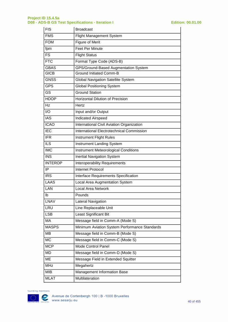
Project ID 15.4.5a D08 - ADS-B GS Test Specifications - Iteration I Edition: 00.01.00
40 of 455
FIS Broadcast
FMS Flight Management System
FOM Figure of Merit
fpm Feet Per Minute
FS Flight Status
FTC Format Type Code (ADS-B)
GBAS GPS/Ground-Based Augmentation System GICB Ground Initiated Comm-B
GNSS Global Navigation Satellite System
GPS Global Positioning System
GS Ground Station
HDOP Horizontal Dilution of Precision
Hz Hertz
I/O Input and/or Output
IAS Indicated Airspeed
ICAO International Civil Aviation Organization
IEC International Electrotechnical Commission
IFR Instrument Flight Rules
ILS Instrument Landing System
IMC Instrument Meteorological Conditions
INS Inertial Navigation System
INTEROP Interoperability Requirements
IP Internet Protocol
IRS Interface Requirements Specification
LAAS Local Area Augmentation System
LAN Local Area Network
lb Pounds
LNAV Lateral Navigation
LRU Line Replaceable Unit
LSB Least Significant Bit
MA Message field in Comm-A (Mode S)
MASPS Minimum Aviation System Performance Standards
MB Message field in Comm-B (Mode S)
MC Message field in Comm-C (Mode S)
MCP Mode Control Panel
MD Message field in Comm-D (Mode S)
ME Message Field in Extended Squitter
MHz Megahertz
MIB Management Information Base
MLAT Multilateration
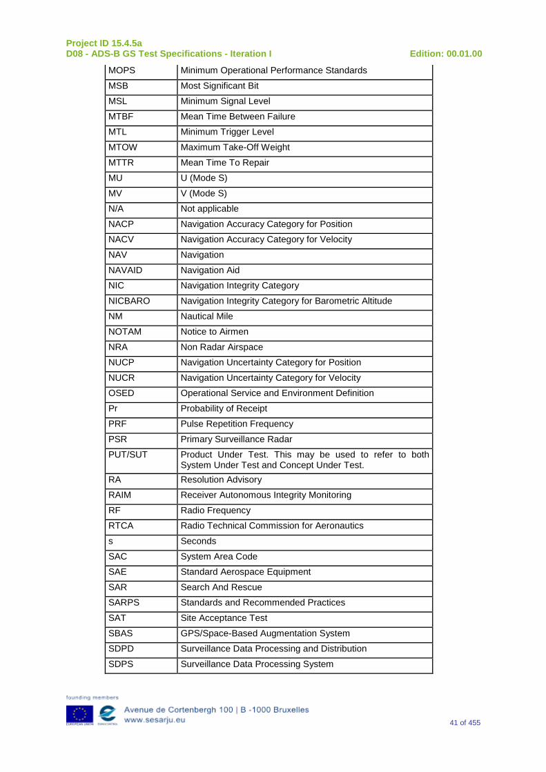
Project ID 15.4.5a D08 - ADS-B GS Test Specifications - Iteration I Edition: 00.01.00
41 of 455
MOPS Minimum Operational Performance Standards
MSB Most Significant Bit
MSL Minimum Signal Level
MTBF Mean Time Between Failure
MTL Minimum Trigger Level
MTOW Maximum Take-Off Weight
MTTR Mean Time To Repair
MU U (Mode S)
MV V (Mode S)
N/A Not applicable
NACP Navigation Accuracy Category for Position
NACV Navigation Accuracy Category for Velocity
NAV Navigation
NAVAID Navigation Aid
NIC Navigation Integrity Category
NICBARO Navigation Integrity Category for Barometric Altitude
NM Nautical Mile
NOTAM Notice to Airmen
NRA Non Radar Airspace
NUCP Navigation Uncertainty Category for Position
NUCR Navigation Uncertainty Category for Velocity
OSED Operational Service and Environment Definition
Pr Probability of Receipt
PRF Pulse Repetition Frequency
PSR Primary Surveillance Radar
PUT/SUT Product Under Test. This may be used to refer to both System Under Test and Concept Under Test.
RA Resolution Advisory
RAIM Receiver Autonomous Integrity Monitoring
RF Radio Frequency
RTCA Radio Technical Commission for Aeronautics
s Seconds
SAC System Area Code
SAE Standard Aerospace Equipment
SAR Search And Rescue
SARPS Standards and Recommended Practices
SAT Site Acceptance Test
SBAS GPS/Space-Based Augmentation System
SDPD Surveillance Data Processing and Distribution
SDPS Surveillance Data Processing System
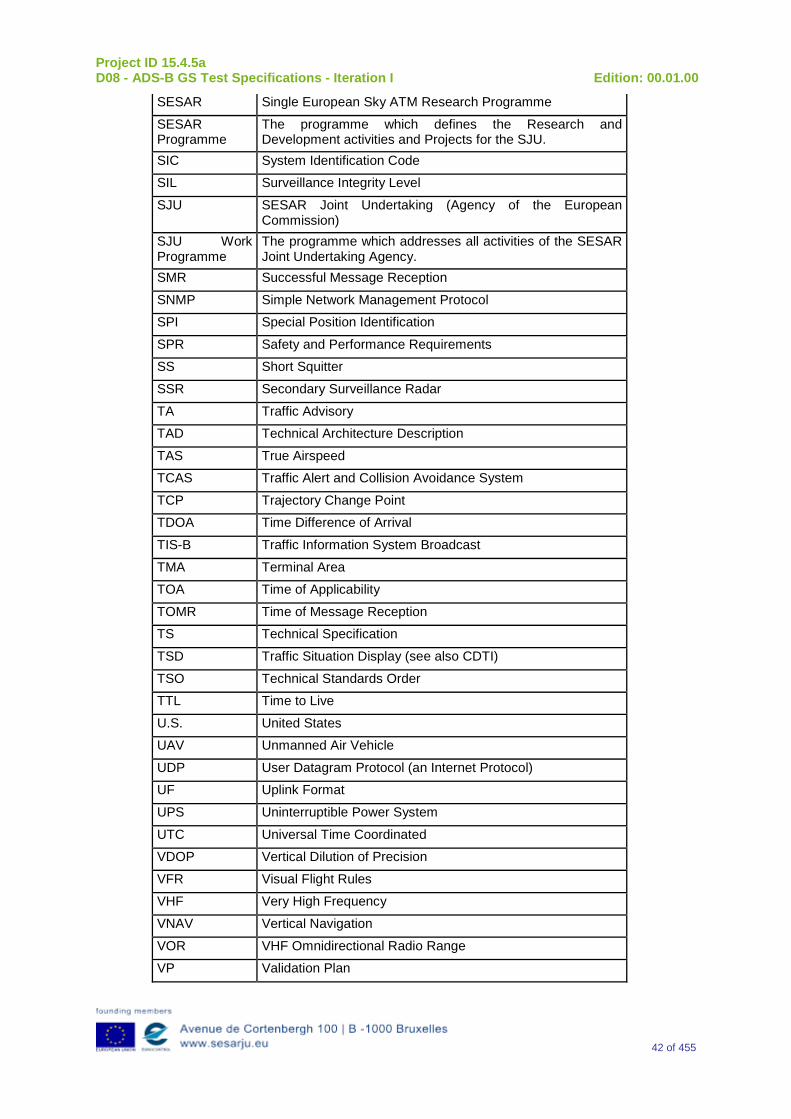
Project ID 15.4.5a D08 - ADS-B GS Test Specifications - Iteration I Edition: 00.01.00
42 of 455
SESAR Single European Sky ATM Research Programme
SESAR Programme
The programme which defines the Research and Development activities and Projects for the SJU.
SIC System Identification Code
SIL Surveillance Integrity Level
SJU SESAR Joint Undertaking (Agency of the European Commission)
SJU Work Programme
The programme which addresses all activities of the SESAR Joint Undertaking Agency.
SMR Successful Message Reception
SNMP Simple Network Management Protocol
SPI Special Position Identification
SPR Safety and Performance Requirements
SS Short Squitter
SSR Secondary Surveillance Radar
TA Traffic Advisory
TAD Technical Architecture Description
TAS True Airspeed
TCAS Traffic Alert and Collision Avoidance System
TCP Trajectory Change Point
TDOA Time Difference of Arrival
TIS-B Traffic Information System Broadcast
TMA Terminal Area
TOA Time of Applicability
TOMR Time of Message Reception
TS Technical Specification
TSD Traffic Situation Display (see also CDTI)
TSO Technical Standards Order
TTL Time to Live
U.S. United States
UAV Unmanned Air Vehicle
UDP User Datagram Protocol (an Internet Protocol)
UF Uplink Format
UPS Uninterruptible Power System
UTC Universal Time Coordinated
VDOP Vertical Dilution of Precision
VFR Visual Flight Rules
VHF Very High Frequency
VNAV Vertical Navigation
VOR VHF Omnidirectional Radio Range
VP Validation Plan
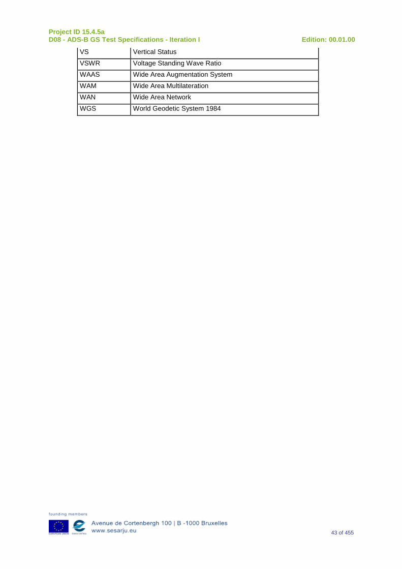
Project ID 15.4.5a D08 - ADS-B GS Test Specifications - Iteration I Edition: 00.01.00
43 of 455
VS Vertical Status
VSWR Voltage Standing Wave Ratio
WAAS Wide Area Augmentation System
WAM Wide Area Multilateration
WAN Wide Area Network
WGS World Geodetic System 1984
Project ID 15.4.5a D08 - ADS-B GS Test Specifications - Iteration I Edition: 00.01.00
44 of 455
2 Context of the Verification The scope of this Verification Plan addresses the ADS-B Ground Station to be developed under the requirements defined in D18 ADS-B Surveillance System Specifications, Ref. [2] D05 ADS-B Ground Station Specifications, Ref. [3] and D07 Interface Specifications, Ref.[4] in Project 15.4.5b.
Main addressed stakeholders are Manufacturers of the ADS-B Ground Station prototypes, ANSPs and ATM Organizations, such as EUROCONTROL.
Project 15.4.5a has developed these test specifications in order to provide Project 15.4.5b with a main input to perform the verification of some prototypes: Project 15.4.5b will take this input and will refine and perform a tailoring of it to suit Project 15.4.5b’s needs.
Therefore, the Verification activities will be performed in Project 15.4.5b.
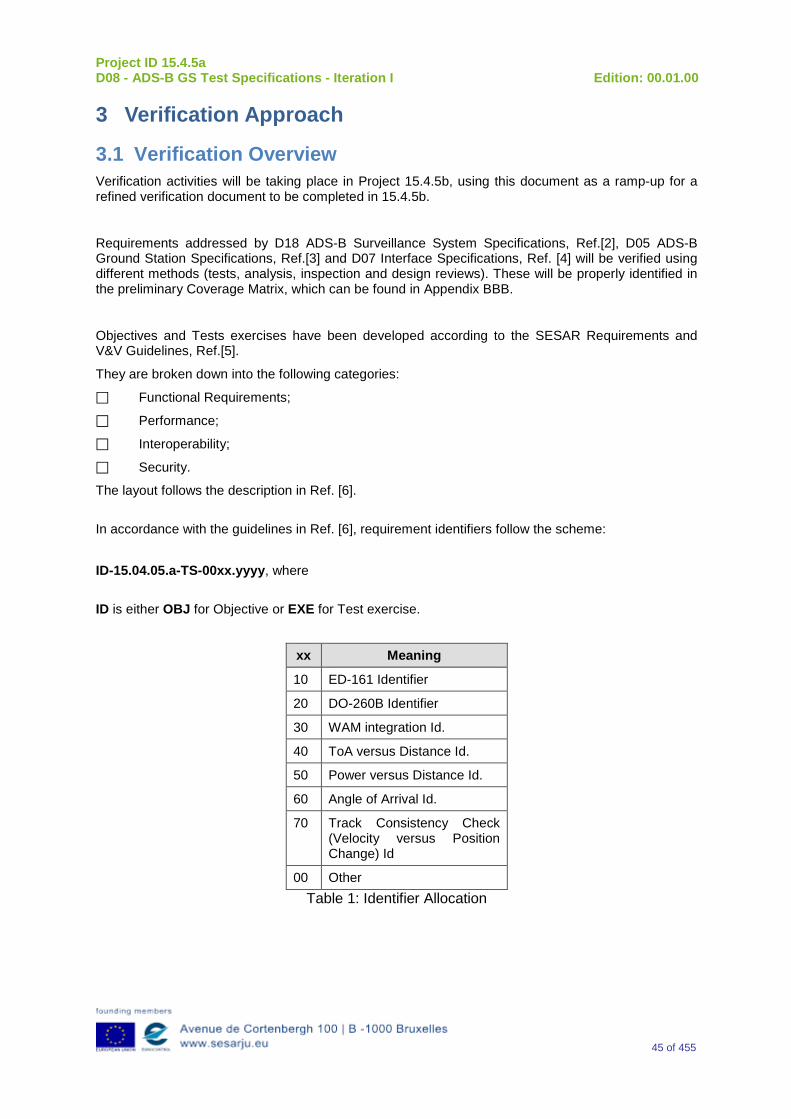
Project ID 15.4.5a D08 - ADS-B GS Test Specifications - Iteration I Edition: 00.01.00
45 of 455
3 Verification Approach
3.1 Verification Overview Verification activities will be taking place in Project 15.4.5b, using this document as a ramp-up for a refined verification document to be completed in 15.4.5b.
Requirements addressed by D18 ADS-B Surveillance System Specifications, Ref.[2], D05 ADS-B Ground Station Specifications, Ref.[3] and D07 Interface Specifications, Ref. [4] will be verified using different methods (tests, analysis, inspection and design reviews). These will be properly identified in the preliminary Coverage Matrix, which can be found in Appendix BBB.
Objectives and Tests exercises have been developed according to the SESAR Requirements and V&V Guidelines, Ref.[5].
They are broken down into the following categories:
Functional Requirements;
Performance;
Interoperability;
Security.
The layout follows the description in Ref. [6]. In accordance with the guidelines in Ref. [6], requirement identifiers follow the scheme: ID-15.04.05.a-TS-00xx.yyyy, where ID is either OBJ for Objective or EXE for Test exercise.
xx Meaning
10 ED-161 Identifier
20 DO-260B Identifier
30 WAM integration Id.
40 ToA versus Distance Id.
50 Power versus Distance Id.
60 Angle of Arrival Id.
70 Track Consistency Check (Velocity versus Position Change) Id
00 Other Table 1: Identifier Allocation
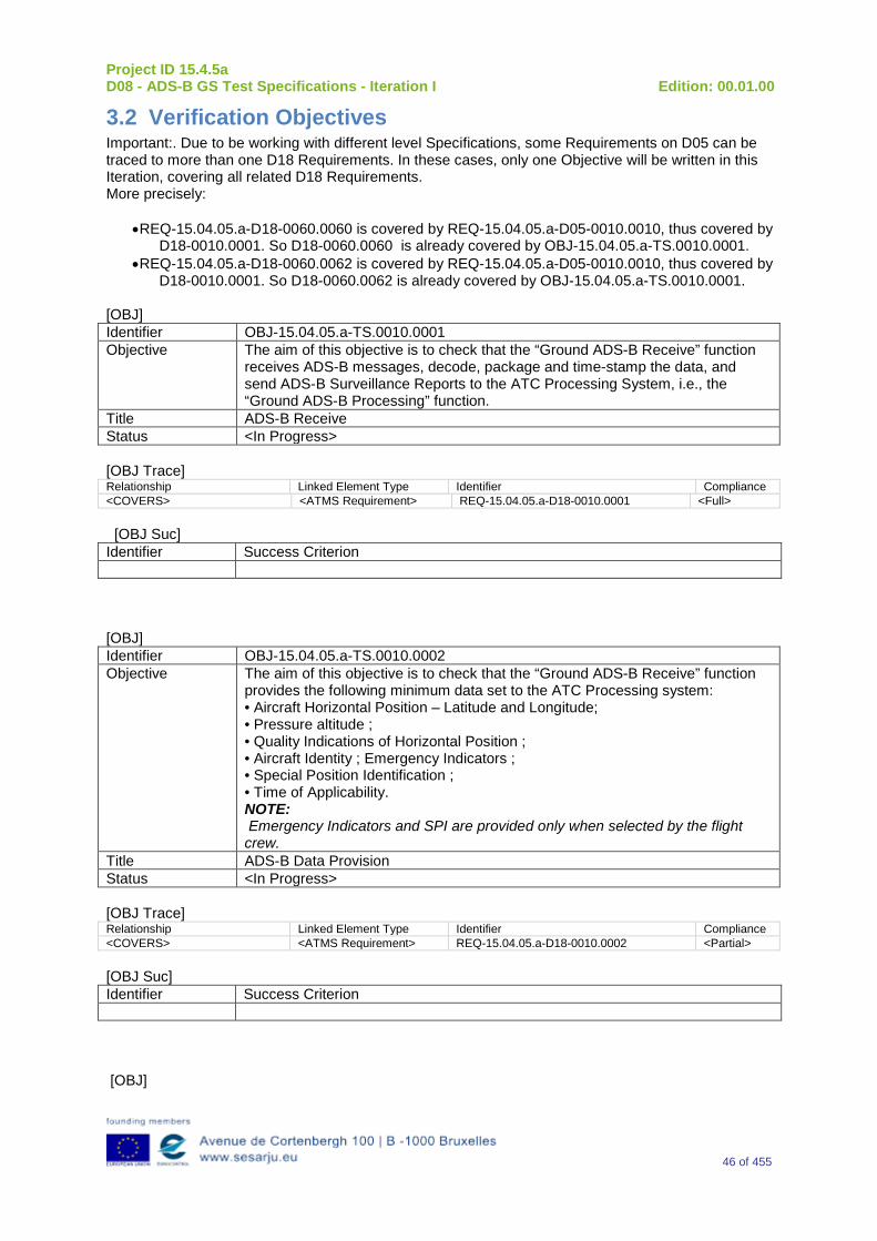
Project ID 15.4.5a D08 - ADS-B GS Test Specifications - Iteration I Edition: 00.01.00
46 of 455
3.2 Verification Objectives Important:. Due to be working with different level Specifications, some Requirements on D05 can be traced to more than one D18 Requirements. In these cases, only one Objective will be written in this Iteration, covering all related D18 Requirements. More precisely:
•REQ-15.04.05.a-D18-0060.0060 is covered by REQ-15.04.05.a-D05-0010.0010, thus covered by D18-0010.0001. So D18-0060.0060 is already covered by OBJ-15.04.05.a-TS.0010.0001.
•REQ-15.04.05.a-D18-0060.0062 is covered by REQ-15.04.05.a-D05-0010.0010, thus covered by D18-0010.0001. So D18-0060.0062 is already covered by OBJ-15.04.05.a-TS.0010.0001.
[OBJ] Identifier OBJ-15.04.05.a-TS.0010.0001 Objective The aim of this objective is to check that the “Ground ADS-B Receive” function
receives ADS-B messages, decode, package and time-stamp the data, and send ADS-B Surveillance Reports to the ATC Processing System, i.e., the “Ground ADS-B Processing” function.
Title ADS-B Receive Status <In Progress> [OBJ Trace] Relationship Linked Element Type Identifier Compliance <COVERS> <ATMS Requirement> REQ-15.04.05.a-D18-0010.0001 <Full> [OBJ Suc] Identifier Success Criterion [OBJ] Identifier OBJ-15.04.05.a-TS.0010.0002 Objective The aim of this objective is to check that the “Ground ADS-B Receive” function
provides the following minimum data set to the ATC Processing system: • Aircraft Horizontal Position – Latitude and Longitude; • Pressure altitude ; • Quality Indications of Horizontal Position ; • Aircraft Identity ; Emergency Indicators ; • Special Position Identification ; • Time of Applicability. NOTE: Emergency Indicators and SPI are provided only when selected by the flight crew.
Title ADS-B Data Provision Status <In Progress> [OBJ Trace] Relationship Linked Element Type Identifier Compliance <COVERS> <ATMS Requirement> REQ-15.04.05.a-D18-0010.0002 <Partial> [OBJ Suc] Identifier Success Criterion [OBJ]
Project ID 15.4.5a D08 - ADS-B GS Test Specifications - Iteration I Edition: 00.01.00
47 of 455
Identifier OBJ-15.04.05.a-TS.0010.0003 Objective The aim of this objective is to check that when direct recognition procedures are
used by the ATCO for identification, the ADS-B Ground Domain contains a function to ensure the aircraft identity data that is broadcast is retained and correctly associated with the position information for display,
Title Aircraft Identity Retain Status <In Progress> [OBJ Trace] Relationship Linked Element Type Identifier Compliance <COVERS> <ATMS Requirement> REQ-15.04.05.a-D18-0010.0003 <Partial> [OBJ Suc] Identifier Success Criterion [OBJ] Identifier OBJ-15.04.05.a-TS.0010.0004 Objective The aim of this objective is to check that the “Ground ADS-B Receive” function
provides in each ADS-B surveillance report a time of applicability (Interface E2) of the position information
Title Time Of Applicability provision Status <In Progress> [OBJ Trace] Relationship Linked Element Type Identifier Compliance <COVERS> <ATMS Requirement> REQ-15.04.05.a-D18-0010.0004 <Partial> [OBJ Suc] Identifier Success Criterion [OBJ] Identifier OBJ-15.04.05.a-TS.0010.0005 Objective The aim of this objective is to check that If the time of applicability within each
ADS-B surveillance report is not applicable for all data items of that report (interface E2), the “Ground ADS-B Receive” function provides separate times of applicability for the specific data items that differ,
Title Separate Times Of Applicability provision Status <In Progress> [OBJ Trace] Relationship Linked Element Type Identifier Compliance <COVERS> <ATMS Requirement> REQ-15.04.05.a-D18-0010.0005 <Partial> [OBJ Suc] Identifier Success Criterion [OBJ] Identifier OBJ-15.04.05.a-TS.0010.0006 Objective The aim of this objective is to check that the “Ground ADS-B Surveillance
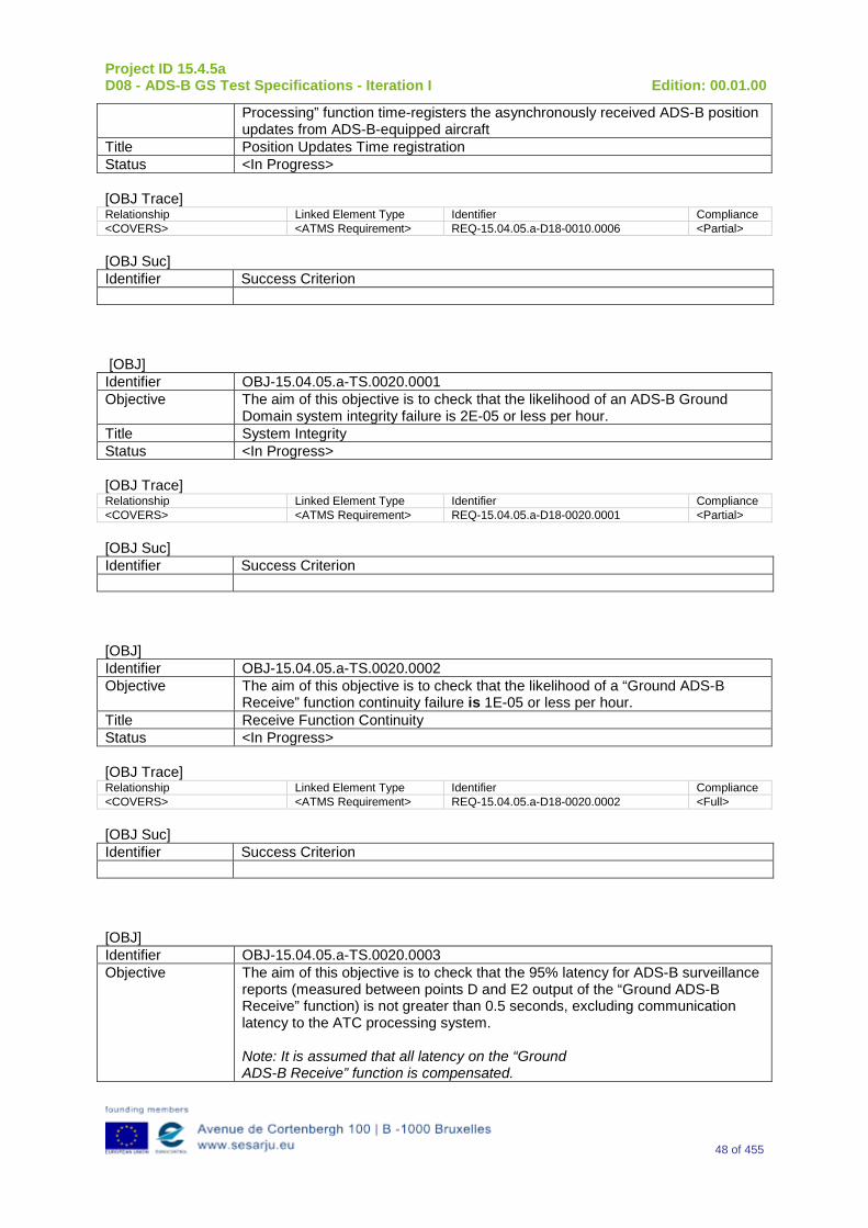
Project ID 15.4.5a D08 - ADS-B GS Test Specifications - Iteration I Edition: 00.01.00
48 of 455
Processing” function time-registers the asynchronously received ADS-B position updates from ADS-B-equipped aircraft
Title Position Updates Time registration Status <In Progress> [OBJ Trace] Relationship Linked Element Type Identifier Compliance <COVERS> <ATMS Requirement> REQ-15.04.05.a-D18-0010.0006 <Partial> [OBJ Suc] Identifier Success Criterion [OBJ] Identifier OBJ-15.04.05.a-TS.0020.0001 Objective The aim of this objective is to check that the likelihood of an ADS-B Ground
Domain system integrity failure is 2E-05 or less per hour. Title System Integrity Status <In Progress> [OBJ Trace] Relationship Linked Element Type Identifier Compliance <COVERS> <ATMS Requirement> REQ-15.04.05.a-D18-0020.0001 <Partial> [OBJ Suc] Identifier Success Criterion [OBJ] Identifier OBJ-15.04.05.a-TS.0020.0002 Objective The aim of this objective is to check that the likelihood of a “Ground ADS-B
Receive” function continuity failure is 1E-05 or less per hour. Title Receive Function Continuity Status <In Progress> [OBJ Trace] Relationship Linked Element Type Identifier Compliance <COVERS> <ATMS Requirement> REQ-15.04.05.a-D18-0020.0002 <Full> [OBJ Suc] Identifier Success Criterion [OBJ] Identifier OBJ-15.04.05.a-TS.0020.0003 Objective The aim of this objective is to check that the 95% latency for ADS-B surveillance
reports (measured between points D and E2 output of the “Ground ADS-B Receive” function) is not greater than 0.5 seconds, excluding communication latency to the ATC processing system. Note: It is assumed that all latency on the “Ground ADS-B Receive” function is compensated.
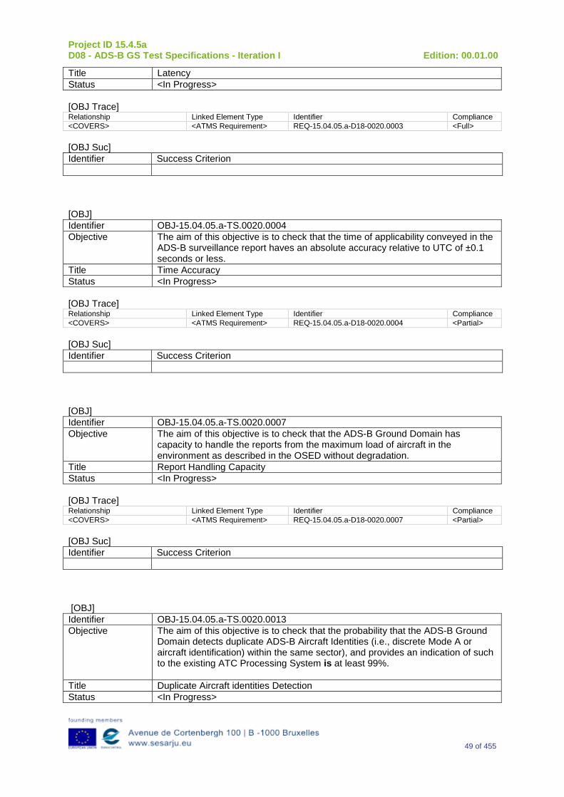
Project ID 15.4.5a D08 - ADS-B GS Test Specifications - Iteration I Edition: 00.01.00
49 of 455
Title Latency Status <In Progress> [OBJ Trace] Relationship Linked Element Type Identifier Compliance <COVERS> <ATMS Requirement> REQ-15.04.05.a-D18-0020.0003 <Full> [OBJ Suc] Identifier Success Criterion [OBJ] Identifier OBJ-15.04.05.a-TS.0020.0004 Objective The aim of this objective is to check that the time of applicability conveyed in the
ADS-B surveillance report haves an absolute accuracy relative to UTC of ±0.1 seconds or less.
Title Time Accuracy Status <In Progress> [OBJ Trace] Relationship Linked Element Type Identifier Compliance <COVERS> <ATMS Requirement> REQ-15.04.05.a-D18-0020.0004 <Partial> [OBJ Suc] Identifier Success Criterion [OBJ] Identifier OBJ-15.04.05.a-TS.0020.0007 Objective The aim of this objective is to check that the ADS-B Ground Domain has
capacity to handle the reports from the maximum load of aircraft in the environment as described in the OSED without degradation.
Title Report Handling Capacity Status <In Progress> [OBJ Trace] Relationship Linked Element Type Identifier Compliance <COVERS> <ATMS Requirement> REQ-15.04.05.a-D18-0020.0007 <Partial> [OBJ Suc] Identifier Success Criterion [OBJ] Identifier OBJ-15.04.05.a-TS.0020.0013 Objective The aim of this objective is to check that the probability that the ADS-B Ground
Domain detects duplicate ADS-B Aircraft Identities (i.e., discrete Mode A or aircraft identification) within the same sector), and provides an indication of such to the existing ATC Processing System is at least 99%.
Title Duplicate Aircraft identities Detection Status <In Progress>
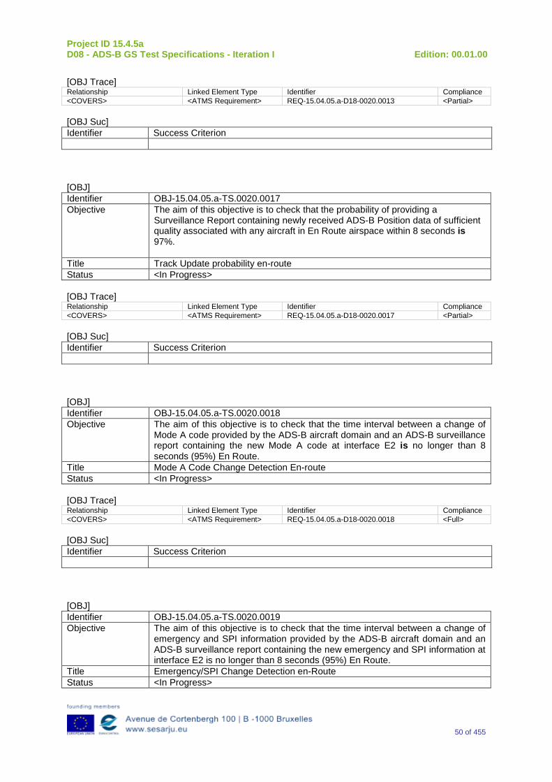
Project ID 15.4.5a D08 - ADS-B GS Test Specifications - Iteration I Edition: 00.01.00
50 of 455
[OBJ Trace] Relationship Linked Element Type Identifier Compliance <COVERS> <ATMS Requirement> REQ-15.04.05.a-D18-0020.0013 <Partial> [OBJ Suc] Identifier Success Criterion [OBJ] Identifier OBJ-15.04.05.a-TS.0020.0017 Objective The aim of this objective is to check that the probability of providing a
Surveillance Report containing newly received ADS-B Position data of sufficient quality associated with any aircraft in En Route airspace within 8 seconds is 97%.
Title Track Update probability en-route Status <In Progress> [OBJ Trace] Relationship Linked Element Type Identifier Compliance <COVERS> <ATMS Requirement> REQ-15.04.05.a-D18-0020.0017 <Partial> [OBJ Suc] Identifier Success Criterion [OBJ] Identifier OBJ-15.04.05.a-TS.0020.0018 Objective The aim of this objective is to check that the time interval between a change of
Mode A code provided by the ADS-B aircraft domain and an ADS-B surveillance report containing the new Mode A code at interface E2 is no longer than 8 seconds (95%) En Route.
Title Mode A Code Change Detection En-route Status <In Progress> [OBJ Trace] Relationship Linked Element Type Identifier Compliance <COVERS> <ATMS Requirement> REQ-15.04.05.a-D18-0020.0018 <Full> [OBJ Suc] Identifier Success Criterion [OBJ] Identifier OBJ-15.04.05.a-TS.0020.0019 Objective The aim of this objective is to check that the time interval between a change of
emergency and SPI information provided by the ADS-B aircraft domain and an ADS-B surveillance report containing the new emergency and SPI information at interface E2 is no longer than 8 seconds (95%) En Route.
Title Emergency/SPI Change Detection en-Route Status <In Progress>
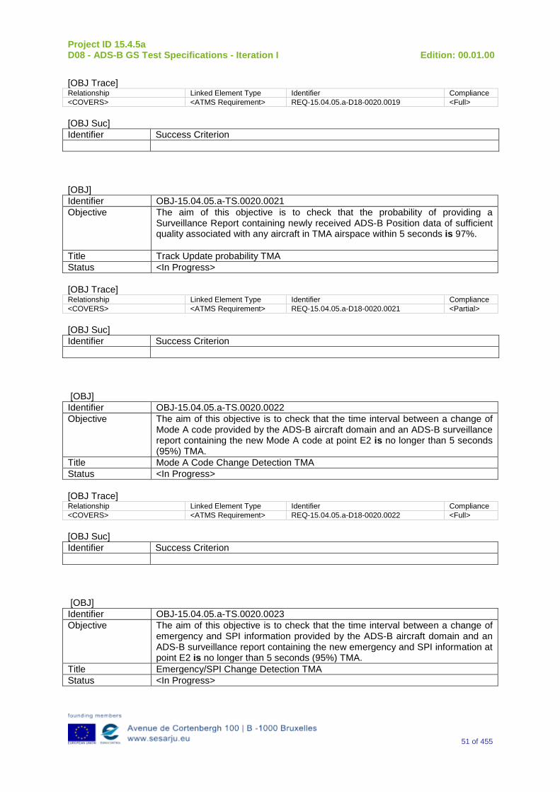
Project ID 15.4.5a D08 - ADS-B GS Test Specifications - Iteration I Edition: 00.01.00
51 of 455
[OBJ Trace] Relationship Linked Element Type Identifier Compliance <COVERS> <ATMS Requirement> REQ-15.04.05.a-D18-0020.0019 <Full> [OBJ Suc] Identifier Success Criterion [OBJ] Identifier OBJ-15.04.05.a-TS.0020.0021 Objective The aim of this objective is to check that the probability of providing a
Surveillance Report containing newly received ADS-B Position data of sufficient quality associated with any aircraft in TMA airspace within 5 seconds is 97%.
Title Track Update probability TMA Status <In Progress> [OBJ Trace] Relationship Linked Element Type Identifier Compliance <COVERS> <ATMS Requirement> REQ-15.04.05.a-D18-0020.0021 <Partial> [OBJ Suc] Identifier Success Criterion [OBJ] Identifier OBJ-15.04.05.a-TS.0020.0022 Objective The aim of this objective is to check that the time interval between a change of
Mode A code provided by the ADS-B aircraft domain and an ADS-B surveillance report containing the new Mode A code at point E2 is no longer than 5 seconds (95%) TMA.
Title Mode A Code Change Detection TMA Status <In Progress> [OBJ Trace] Relationship Linked Element Type Identifier Compliance <COVERS> <ATMS Requirement> REQ-15.04.05.a-D18-0020.0022 <Full> [OBJ Suc] Identifier Success Criterion [OBJ] Identifier OBJ-15.04.05.a-TS.0020.0023 Objective The aim of this objective is to check that the time interval between a change of
emergency and SPI information provided by the ADS-B aircraft domain and an ADS-B surveillance report containing the new emergency and SPI information at point E2 is no longer than 5 seconds (95%) TMA.
Title Emergency/SPI Change Detection TMA Status <In Progress>
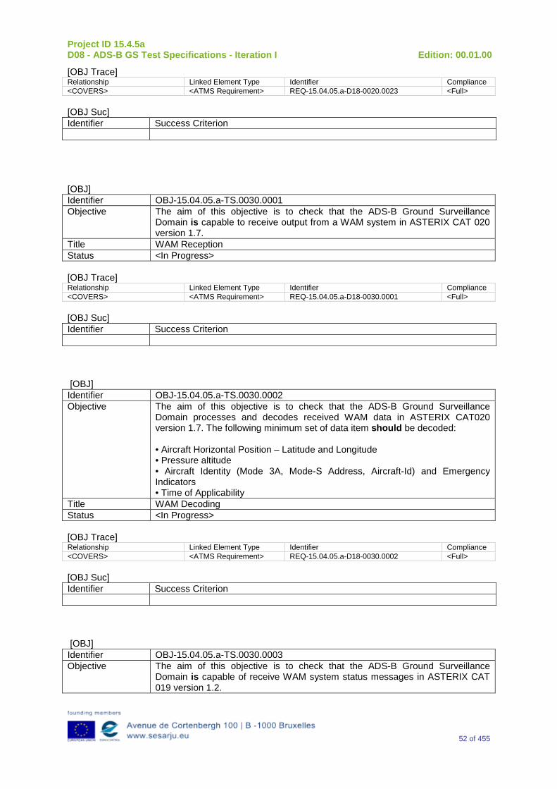
Project ID 15.4.5a D08 - ADS-B GS Test Specifications - Iteration I Edition: 00.01.00
52 of 455
[OBJ Trace] Relationship Linked Element Type Identifier Compliance <COVERS> <ATMS Requirement> REQ-15.04.05.a-D18-0020.0023 <Full> [OBJ Suc] Identifier Success Criterion [OBJ] Identifier OBJ-15.04.05.a-TS.0030.0001 Objective The aim of this objective is to check that the ADS-B Ground Surveillance
Domain is capable to receive output from a WAM system in ASTERIX CAT 020 version 1.7.
Title WAM Reception Status <In Progress> [OBJ Trace] Relationship Linked Element Type Identifier Compliance <COVERS> <ATMS Requirement> REQ-15.04.05.a-D18-0030.0001 <Full> [OBJ Suc] Identifier Success Criterion [OBJ] Identifier OBJ-15.04.05.a-TS.0030.0002 Objective The aim of this objective is to check that the ADS-B Ground Surveillance
Domain processes and decodes received WAM data in ASTERIX CAT020 version 1.7. The following minimum set of data item should be decoded: • Aircraft Horizontal Position – Latitude and Longitude • Pressure altitude • Aircraft Identity (Mode 3A, Mode-S Address, Aircraft-Id) and Emergency Indicators • Time of Applicability
Title WAM Decoding Status <In Progress> [OBJ Trace] Relationship Linked Element Type Identifier Compliance <COVERS> <ATMS Requirement> REQ-15.04.05.a-D18-0030.0002 <Full> [OBJ Suc] Identifier Success Criterion [OBJ] Identifier OBJ-15.04.05.a-TS.0030.0003 Objective The aim of this objective is to check that the ADS-B Ground Surveillance
Domain is capable of receive WAM system status messages in ASTERIX CAT 019 version 1.2.
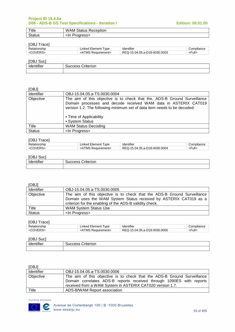
Project ID 15.4.5a D08 - ADS-B GS Test Specifications - Iteration I Edition: 00.01.00
53 of 455
Title WAM Status Reception Status <In Progress> [OBJ Trace] Relationship Linked Element Type Identifier Compliance <COVERS> <ATMS Requirement> REQ-15.04.05.a-D18-0030.0003 <Full> [OBJ Suc] Identifier Success Criterion [OBJ] Identifier OBJ-15.04.05.a-TS.0030.0004 Objective The aim of this objective is to check that the, ADS-B Ground Surveillance
Domain processes and decode received WAM data in ASTERIX CAT019 version 1.2. The following minimum set of data item needs to be decoded: • Time of Applicability • System Status
Title WAM Status Decoding Status <In Progress> [OBJ Trace] Relationship Linked Element Type Identifier Compliance <COVERS> <ATMS Requirement> REQ-15.04.05.a-D18-0030.0004 <Full> [OBJ Suc] Identifier Success Criterion [OBJ] Identifier OBJ-15.04.05.a-TS.0030.0005 Objective The aim of this objective is to check that the ADS-B Ground Surveillance
Domain uses the WAM System Status received by ASTERIX CAT019 as a criterion for the enabling of the ADS-B validity check.
Title WAM System Status Use Status <In Progress> [OBJ Trace] Relationship Linked Element Type Identifier Compliance <COVERS> <ATMS Requirement> REQ-15.04.05.a-D18-0030.0005 <Full> [OBJ Suc] Identifier Success Criterion [OBJ] Identifier OBJ-15.04.05.a-TS.0030.0006 Objective The aim of this objective is to check that the ADS-B Ground Surveillance
Domain correlates ADS-B reports received through 1090ES with reports received from a WAM System in ASTERIX CAT020 version 1.7.
Title ADS-B/WAM Report association
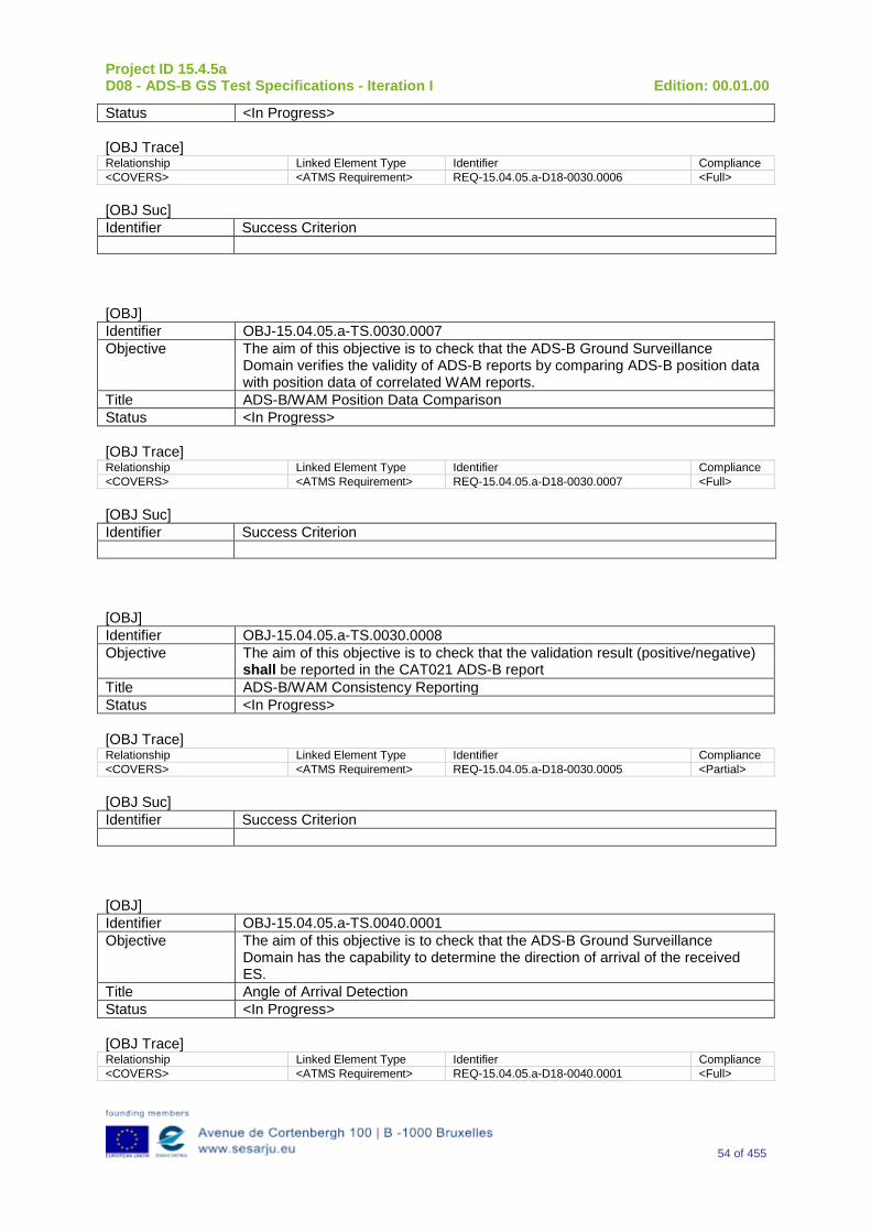
Project ID 15.4.5a D08 - ADS-B GS Test Specifications - Iteration I Edition: 00.01.00
54 of 455
Status <In Progress> [OBJ Trace] Relationship Linked Element Type Identifier Compliance <COVERS> <ATMS Requirement> REQ-15.04.05.a-D18-0030.0006 <Full> [OBJ Suc] Identifier Success Criterion [OBJ] Identifier OBJ-15.04.05.a-TS.0030.0007 Objective The aim of this objective is to check that the ADS-B Ground Surveillance
Domain verifies the validity of ADS-B reports by comparing ADS-B position data with position data of correlated WAM reports.
Title ADS-B/WAM Position Data Comparison Status <In Progress> [OBJ Trace] Relationship Linked Element Type Identifier Compliance <COVERS> <ATMS Requirement> REQ-15.04.05.a-D18-0030.0007 <Full> [OBJ Suc] Identifier Success Criterion [OBJ] Identifier OBJ-15.04.05.a-TS.0030.0008 Objective The aim of this objective is to check that the validation result (positive/negative)
shall be reported in the CAT021 ADS-B report Title ADS-B/WAM Consistency Reporting Status <In Progress> [OBJ Trace] Relationship Linked Element Type Identifier Compliance <COVERS> <ATMS Requirement> REQ-15.04.05.a-D18-0030.0005 <Partial> [OBJ Suc] Identifier Success Criterion [OBJ] Identifier OBJ-15.04.05.a-TS.0040.0001 Objective The aim of this objective is to check that the ADS-B Ground Surveillance
Domain has the capability to determine the direction of arrival of the received ES.
Title Angle of Arrival Detection Status <In Progress> [OBJ Trace] Relationship Linked Element Type Identifier Compliance <COVERS> <ATMS Requirement> REQ-15.04.05.a-D18-0040.0001 <Full>
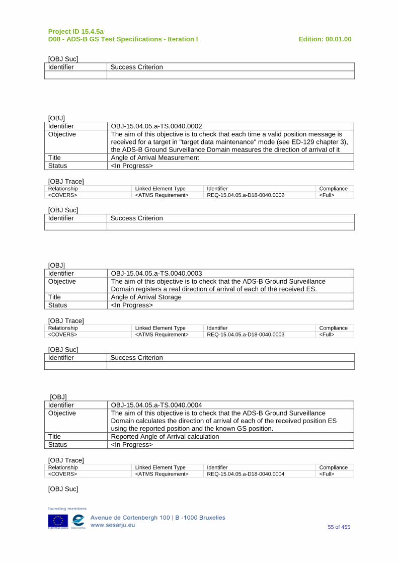
Project ID 15.4.5a D08 - ADS-B GS Test Specifications - Iteration I Edition: 00.01.00
55 of 455
[OBJ Suc] Identifier Success Criterion
[OBJ] Identifier OBJ-15.04.05.a-TS.0040.0002 Objective The aim of this objective is to check that each time a valid position message is
received for a target in "target data maintenance" mode (see ED-129 chapter 3), the ADS-B Ground Surveillance Domain measures the direction of arrival of it
Title Angle of Arrival Measurement Status <In Progress> [OBJ Trace] Relationship Linked Element Type Identifier Compliance <COVERS> <ATMS Requirement> REQ-15.04.05.a-D18-0040.0002 <Full> [OBJ Suc] Identifier Success Criterion
[OBJ] Identifier OBJ-15.04.05.a-TS.0040.0003 Objective The aim of this objective is to check that the ADS-B Ground Surveillance
Domain registers a real direction of arrival of each of the received ES. Title Angle of Arrival Storage Status <In Progress> [OBJ Trace] Relationship Linked Element Type Identifier Compliance <COVERS> <ATMS Requirement> REQ-15.04.05.a-D18-0040.0003 <Full> [OBJ Suc] Identifier Success Criterion
[OBJ] Identifier OBJ-15.04.05.a-TS.0040.0004 Objective The aim of this objective is to check that the ADS-B Ground Surveillance
Domain calculates the direction of arrival of each of the received position ES using the reported position and the known GS position.
Title Reported Angle of Arrival calculation Status <In Progress> [OBJ Trace] Relationship Linked Element Type Identifier Compliance <COVERS> <ATMS Requirement> REQ-15.04.05.a-D18-0040.0004 <Full> [OBJ Suc]
Project ID 15.4.5a D08 - ADS-B GS Test Specifications - Iteration I Edition: 00.01.00
56 of 455
Identifier Success Criterion [OBJ] Identifier OBJ-15.04.05.a-TS.0040.0005 Objective The aim of this objective is to check that the ADS-B Ground Surveillance
Domain compares the real direction of arrival with the calculated direction of arrival using the reported position.
Title Angle of Arrival Verification Status <In Progress> [OBJ Trace] Relationship Linked Element Type Identifier Compliance <COVERS> <ATMS Requirement> REQ-15.04.05.a-D18-0040.0005 <Full> [OBJ Suc] Identifier Success Criterion
[OBJ] Identifier OBJ-15.04.05.a-TS.0040.0006 Objective The aim of this objective is to check that if "n" consecutive position updates
defined as "not matching" have been received, then the ADS-B Ground Surveillance Domain marks the message as "direction of arrival Failure".
Title Angle of Arrival Inconsistency Detection Status <In Progress> [OBJ Trace] Relationship Linked Element Type Identifier Compliance <COVERS> <ATMS Requirement> REQ-15.04.05.a-D18-0040.0006 <Full> [OBJ Suc] Identifier Success Criterion
[OBJ] Identifier OBJ-15.04.05.a-TS.0040.0007 Objective The aim of this objective is to check that the ADS-B Ground Surveillance
Domain reports “direction of arrival failures” in ADS-B reports created out of marked messages.
Title Direction of Arrival Failure Reporting Status <In Progress> [OBJ Trace] Relationship Linked Element Type Identifier Compliance <COVERS> <ATMS Requirement> REQ-15.04.05.a-D18-0040.0007 <Partial>
Project ID 15.4.5a D08 - ADS-B GS Test Specifications - Iteration I Edition: 00.01.00
57 of 455
[OBJ Suc] Identifier Success Criterion [OBJ] Identifier OBJ-15.04.05.a-TS.0040.0040 Objective The aim of this objective is to check that the ADS-B Ground Surveillance
Domain has the capability to measure the power of the received ES Title ES Reception Power Detection Status <In Progress> [OBJ Trace] Relationship Linked Element Type Identifier Compliance <COVERS> <ATMS Requirement> REQ-15.04.05.a-D18-0040.0040 <Full> [OBJ Suc] Identifier Success Criterion [OBJ] Identifier OBJ-15.04.05.a-TS.0040.0041 Objective The aim of this objective is to check that the ADS-B Ground Surveillance
Domain is capable to detect the equipment class of the transmitting aircraft. Title Equipment Class Detection Status <In Progress> [OBJ Trace] Relationship Linked Element Type Identifier Compliance <COVERS> <ATMS Requirement> REQ-15.04.05.a-D18-0040.0041 <Full> [OBJ Suc] Identifier Success Criterion [OBJ] Identifier OBJ-15.04.05.a-TS.0040.0042 Objective The aim of this objective is to check that once a valid position message is
received for a target in "target data maintenance" mode (see ED-129 chapter 3), the ADS-B Ground Surveillance Domain estimates the transmission power of it.
Title ES Reception Power Measurement Status <In Progress> [OBJ Trace] Relationship Linked Element Type Identifier Compliance <COVERS> <ATMS Requirement> REQ-15.04.05.a-D18-0040.0042 <Full> [OBJ Suc] Identifier Success Criterion
Project ID 15.4.5a D08 - ADS-B GS Test Specifications - Iteration I Edition: 00.01.00
58 of 455
[OBJ] Identifier OBJ-15.04.05.a-TS.0040.0043 Objective The aim of this objective is to check that the ADS-B Ground Surveillance
Domain calculates the distance of the target from the ADS-B receiver using the reported position and altitude
Title Expected Reception Power Calculation Status <In Progress> [OBJ Trace] Relationship Linked Element Type Identifier Compliance <COVERS> <ATMS Requirement> REQ-15.04.05.a-D18-0040.0043 <Full> [OBJ Suc] Identifier Success Criterion
[OBJ] Identifier OBJ-15.04.05.a-TS.0040.0044 Objective The aim of this objective is to check that the ADS-B Ground Surveillance
Domain determines the approximate distance of each of the received ES using the measured power and equipment class. (see ED129 appendix F)
Title Reception Power Increment Calculation Status <In Progress> [OBJ Trace] Relationship Linked Element Type Identifier Compliance <COVERS> <ATMS Requirement> REQ-15.04.05.a-D18-0040.0044 <Full> [OBJ Suc] Identifier Success Criterion
[OBJ] Identifier OBJ-15.04.05.a-TS.0040.0045 Objective The aim of this objective is to check that the ADS-B Ground Surveillance
Domain compares the distance obtained from the received position data with the distance calculated using measured power increments.
Title Reception Power Validation Status <In Progress> [OBJ Trace] Relationship Linked Element Type Identifier Compliance <COVERS> <ATMS Requirement> REQ-15.04.05.a-D18-0040.0045 <Full> [OBJ Suc] Identifier Success Criterion
Project ID 15.4.5a D08 - ADS-B GS Test Specifications - Iteration I Edition: 00.01.00
59 of 455
[OBJ] Identifier OBJ-15.04.05.a-TS.0040.0046 Objective The aim of this objective is to check that "n" consecutive position updates for
which the difference between the approximate distance and the reported distance is greater than "x" Nm have been received in "t" seconds, then the ADS-B Ground Surveillance Domain marks the message as "Power/Distance inconsistency".
Title Reception Power Inconsistency Detection Status <In Progress> [OBJ Trace] Relationship Linked Element Type Identifier Compliance <COVERS> <ATMS Requirement> REQ-15.04.05.a-D18-0040.0046 <Full> [OBJ Suc] Identifier Success Criterion [OBJ] Identifier OBJ-15.04.05.a-TS.0040.0047 Objective The aim of this objective is to check that the ADS-B Ground Surveillance
Domain reports “Power/Range inconsistency” in ADS-B reports created out of marked messages.
Title ES Reception Power / Range Inconsistency Reporting Status <In Progress> [OBJ Trace] Relationship Linked Element Type Identifier Compliance <COVERS> <ATMS Requirement> REQ-15.04.05.a-D18-0040.0047 <Partial> [OBJ Suc] Identifier Success Criterion [OBJ] Identifier OBJ-15.04.05.a-TS.0040.0030 Objective The aim of this objective is to check that the ADS-B Ground Surveillance
Domain is capable to determine the distance of a target from an ADS-B receiver by using the received horizontal position data, the received altitude data and the static receiver position.
Title Target Distance calculation Status <In Progress> [OBJ Trace] Relationship Linked Element Type Identifier Compliance <COVERS> <ATMS Requirement> REQ-15.04.05.a-D18-0040.0030 <Full> [OBJ Suc] Identifier Success Criterion
Project ID 15.4.5a D08 - ADS-B GS Test Specifications - Iteration I Edition: 00.01.00
60 of 455
[OBJ] Identifier OBJ-15.04.05.a-TS.0040.0031 Objective The aim of this objective is to check that the ADS-B Ground Surveillance
Domain has a function elaborating the consistency of TOA versus calculated distance from an ADS-B receiver for multiple ADS-B receivers having received the same position squitter.
Title Calculated Distance versus TOA validation Status <In Progress> [OBJ Trace] Relationship Linked Element Type Identifier Compliance <COVERS> <ATMS Requirement> REQ-15.04.05.a-D18-0040.0031 <Full> [OBJ Suc] Identifier Success Criterion [OBJ] Identifier OBJ-15.04.05.a-TS.0040.0032 Objective The aim of this objective is to check that the If "n" consecutive position updates
for which the TOA/distance consistency check yields inconsistent, then the ADS-B Ground Surveillance Domain marks the message as "inconsistent TOA/distance".
Title TOA versus Distance Inconsistency Detection Status <In Progress> [OBJ Trace] Relationship Linked Element Type Identifier Compliance <COVERS> <ATMS Requirement> REQ-15.04.05.a-D18-0040.0032 <Full> [OBJ Suc] Identifier Success Criterion [OBJ] Identifier OBJ-15.04.05.a-TS.0040.0033 Objective The aim of this objective is to check that the ADS-B Ground Surveillance
Domain reports “inconsistent TOA/distance” in ADS-B reports created out of marked messages.
Title ES TOA / Distance Inconsistency Reporting Status <In Progress> [OBJ Trace] Relationship Linked Element Type Identifier Compliance <COVERS> <ATMS Requirement> REQ-15.04.05.a-D18-0040.0033 <Partial> [OBJ Suc] Identifier Success Criterion
Project ID 15.4.5a D08 - ADS-B GS Test Specifications - Iteration I Edition: 00.01.00
61 of 455
[OBJ] Identifier OBJ-15.04.05.a-TS.0060.0061 Objective The aim of this objective is to check that the ADS–B Surveillance System is
capable to decode the ADS-B message, in order to extract the available information, in accordance with the introduced changes in the DO-260B standard.
Title DO-260B Message Decoding Status <In Progress> [OBJ Trace] Relationship Linked Element Type Identifier Compliance <COVERS> <ATMS Requirement> REQ-15.04.05.a-D18-0060.0061 <Full> [OBJ Suc] Identifier Success Criterion
[OBJ] Identifier OBJ-15.04.05.a-TS.0060.0063 Objective The aim of this objective is to check that the ADS-B System ground surveillance
domain is able to transform the introduced DO-260B changes into Standard ASTERIX Category 21 data items.
Title DO-260B encoding into ATX CAT 021 Status <In Progress> [OBJ Trace] Relationship Linked Element Type Identifier Compliance <COVERS> <ATMS Requirement> REQ-15.04.05.a-D18-0060.0063 <Partial> [OBJ Suc] Identifier Success Criterion
[OBJ] Identifier OBJ-15.04.05.a-TS.0070.0064 Objective The aim of this objective is to check that the ADS-B System validates ADS-B
report consistency by evaluating the ADS-B received target velocity against the ADS-B received target position change.
Title Position versus velocity check Status <In Progress> [OBJ Trace] Relationship Linked Element Type Identifier Compliance <COVERS> <ATMS Requirement> REQ-15.04.05.a-D18-0040.0050 <Full> [OBJ Suc] Identifier Success Criterion
Project ID 15.4.5a D08 - ADS-B GS Test Specifications - Iteration I Edition: 00.01.00
62 of 455
3.3 Verification Assumptions
This verification plan is the first iteration of a set of future incoming versions (Iteration 2 and 3). In this way, this iteration has been written using EUROCAE ED129: Technical Specification for a 1090 MHz Extended Squitter ADS-B Ground Station, June 2010 [12] and EUROCAE/RTCA MOPS for 1090ES ADS-B and TIS-B, ED-102A/DO-260B, Dec. 2009 as a reference.
Many of the tests are taken from this document and comply with the requirements based on EUROCAE/RTCA SPIR Document for ADS-B NRA Application, ED-126/DO-303, Dec. 2006 [10].
These tests, will be upgraded in future iterations to include full compliance with all requirements contained in related input documents (D18 ADS-B Surveillance System Specifications, Ref .[2], D05 ADS-B Ground Station Specifications, Ref. [3] and D07 Interface Specifications, Ref. [4]), based on EUROCAE/RTCA SPIR Document for ADS-B RAD Application, ED-161/DO-318, Sept. 2009 [11], as well as to include environment load parameters as described in the OSED, which is to be defined at the time of creation of this first iteration document.
Also it is assumed that in every test of this document, it will be performed the corresponding ASTERIX data field comprobation according to the defined D07 Interface Specifications, Ref. [4] and so it will be marked in the Pass/Fail Result.
3.4 Verification Requirements on the Concept/System Under Test
Verification requirements on the system under test will be declared for each independent test in its procedure.
3.5 Verification Platform Needs This document contains a set of type approval tests that can be used to demonstrate compliance with the objectives in section 3.2. These type approval tests are intended to be performed once in order to provide evidence that the ground station design complies with these requirements, and therefore is not intended as a production test or factory acceptance test activity. These test procedures may also be used as part of a regression test following a design change. It is up to the manufacturer to determine the scope and suitability of regression test activity.
These test procedures were written with the intention of saving manufacturers the time and expense of developing their own tests while providing equipment buyers with a minimum level of assurance that the equipment is compliant with the objectives in section 3.2. Alternative tests may be substituted if it is more convenient to do so as long as any substituted test procedures fully cover all the mandatory requirements of the relevant part of section 3.2.
Since many test procedures require a similar test equipment setup, a standard setup is defined here and specific test procedures reference this section, specifying exceptions when necessary.
Specific test procedures are defined in this Section starting with section 5.2. Except where otherwise noted, the sub-section number of each test procedure matches the corresponding sub-section number within Section 3.2 containing the requirements being tested.
Only mandatory requirements are covered by these tests.
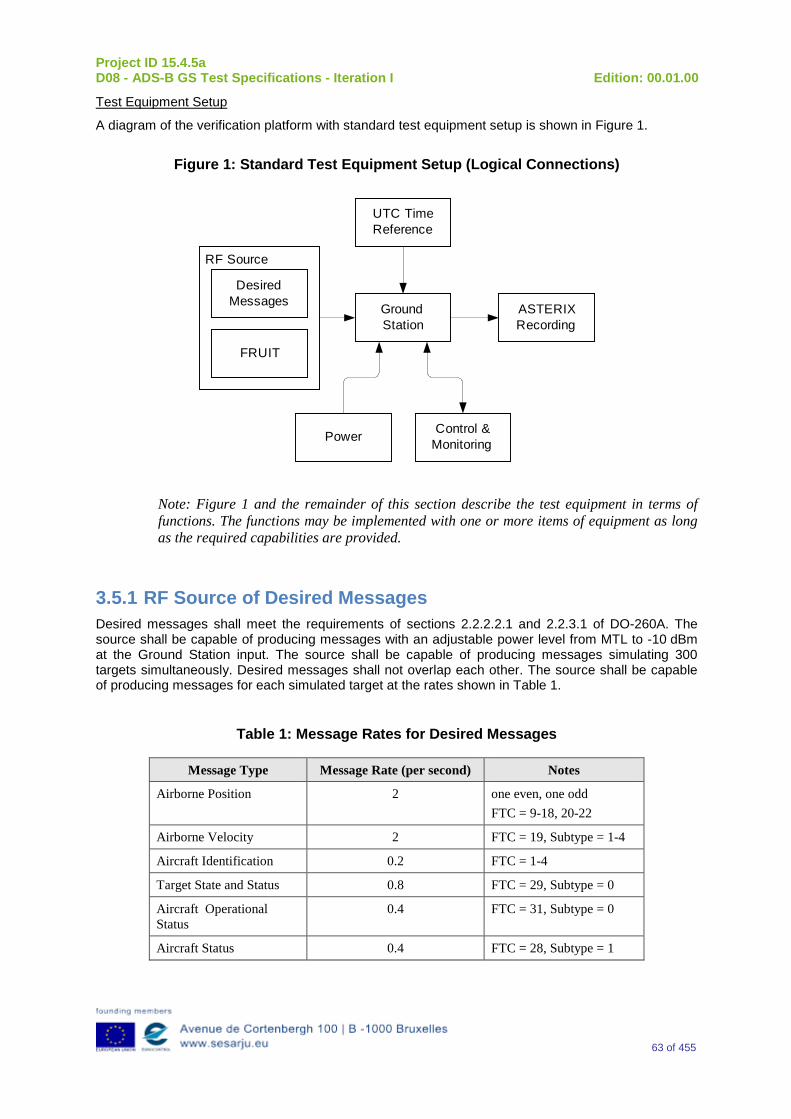
Project ID 15.4.5a D08 - ADS-B GS Test Specifications - Iteration I Edition: 00.01.00
63 of 455
Test Equipment Setup
A diagram of the verification platform with standard test equipment setup is shown in Figure 1.
Figure 1: Standard Test Equipment Setup (Logical Connections)
Ground Station
RF Source
Desired Messages
FRUIT
UTC Time Reference
Power
ASTERIX Recording
Control & Monitoring
Note: Figure 1 and the remainder of this section describe the test equipment in terms of functions. The functions may be implemented with one or more items of equipment as long as the required capabilities are provided.
3.5.1 RF Source of Desired Messages Desired messages shall meet the requirements of sections 2.2.2.2.1 and 2.2.3.1 of DO-260A. The source shall be capable of producing messages with an adjustable power level from MTL to -10 dBm at the Ground Station input. The source shall be capable of producing messages simulating 300 targets simultaneously. Desired messages shall not overlap each other. The source shall be capable of producing messages for each simulated target at the rates shown in Table 1.
Table 1: Message Rates for Desired Messages
Message Type Message Rate (per second) Notes
Airborne Position 2 one even, one odd FTC = 9-18, 20-22
Airborne Velocity 2 FTC = 19, Subtype = 1-4
Aircraft Identification 0.2 FTC = 1-4
Target State and Status 0.8 FTC = 29, Subtype = 0
Aircraft Operational Status
0.4 FTC = 31, Subtype = 0
Aircraft Status 0.4 FTC = 28, Subtype = 1
Project ID 15.4.5a D08 - ADS-B GS Test Specifications - Iteration I Edition: 00.01.00
64 of 455
Dithered transmission intervals, as specified in DO-260A section 2.2.3.3.1, are permissible but not required. Simulated targets may be moving or stationary. Stationary targets must have velocity messages.
3.5.2 RF Source of FRUIT The FRUIT source shall be capable of producing Mode A/C, Mode S short and Mode S long messages randomly distributed in time with the power distribution shown in Table 2.
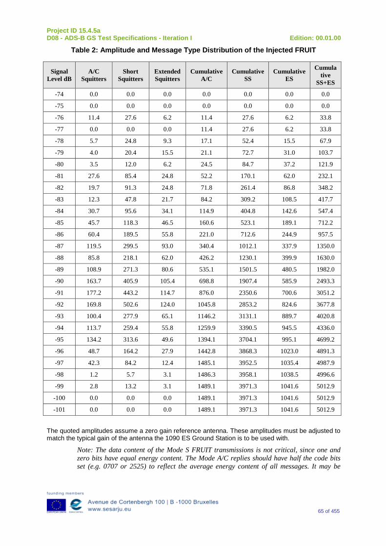
Project ID 15.4.5a D08 - ADS-B GS Test Specifications - Iteration I Edition: 00.01.00
65 of 455
Table 2: Amplitude and Message Type Distribution of the Injected FRUIT
Signal Level dB
A/C Squitters
Short Squitters
Extended Squitters
Cumulative A/C
Cumulative SS
Cumulative ES
Cumulative
SS+ES
-74 0.0 0.0 0.0 0.0 0.0 0.0 0.0
-75 0.0 0.0 0.0 0.0 0.0 0.0 0.0
-76 11.4 27.6 6.2 11.4 27.6 6.2 33.8
-77 0.0 0.0 0.0 11.4 27.6 6.2 33.8
-78 5.7 24.8 9.3 17.1 52.4 15.5 67.9
-79 4.0 20.4 15.5 21.1 72.7 31.0 103.7
-80 3.5 12.0 6.2 24.5 84.7 37.2 121.9
-81 27.6 85.4 24.8 52.2 170.1 62.0 232.1
-82 19.7 91.3 24.8 71.8 261.4 86.8 348.2
-83 12.3 47.8 21.7 84.2 309.2 108.5 417.7
-84 30.7 95.6 34.1 114.9 404.8 142.6 547.4
-85 45.7 118.3 46.5 160.6 523.1 189.1 712.2
-86 60.4 189.5 55.8 221.0 712.6 244.9 957.5
-87 119.5 299.5 93.0 340.4 1012.1 337.9 1350.0
-88 85.8 218.1 62.0 426.2 1230.1 399.9 1630.0
-89 108.9 271.3 80.6 535.1 1501.5 480.5 1982.0
-90 163.7 405.9 105.4 698.8 1907.4 585.9 2493.3
-91 177.2 443.2 114.7 876.0 2350.6 700.6 3051.2
-92 169.8 502.6 124.0 1045.8 2853.2 824.6 3677.8
-93 100.4 277.9 65.1 1146.2 3131.1 889.7 4020.8
-94 113.7 259.4 55.8 1259.9 3390.5 945.5 4336.0
-95 134.2 313.6 49.6 1394.1 3704.1 995.1 4699.2
-96 48.7 164.2 27.9 1442.8 3868.3 1023.0 4891.3
-97 42.3 84.2 12.4 1485.1 3952.5 1035.4 4987.9
-98 1.2 5.7 3.1 1486.3 3958.1 1038.5 4996.6
-99 2.8 13.2 3.1 1489.1 3971.3 1041.6 5012.9
-100 0.0 0.0 0.0 1489.1 3971.3 1041.6 5012.9
-101 0.0 0.0 0.0 1489.1 3971.3 1041.6 5012.9
The quoted amplitudes assume a zero gain reference antenna. These amplitudes must be adjusted to match the typical gain of the antenna the 1090 ES Ground Station is to be used with.
Note: The data content of the Mode S FRUIT transmissions is not critical, since one and zero bits have equal energy content. The Mode A/C replies should have half the code bits set (e.g. 0707 or 2525) to reflect the average energy content of all messages. It may be
Project ID 15.4.5a D08 - ADS-B GS Test Specifications - Iteration I Edition: 00.01.00
66 of 455
useful to use non-ADS-B DF codes (e.g. 20) for the Mode S ES messages to prevent valid FRUIT ADS-B messages from appearing in the ASTERIX data.
3.5.3 UTC Time Reference A means of disabling or disconnecting the UTC time reference shall be provided.
3.5.4 Control and Monitoring Equipment Control and monitoring equipment shall be present as to interface with the 1090 ES Ground Station. A means of polling the Ground Station for values of all parameters shall be provided. The control and monitoring equipment shall allow a user to authenticate with and control the Ground Station.
3.5.5 ASTERIX Recording Equipment The ASTERIX recording equipment shall timestamp and record all ASTERIX reports sent from the 1090 ES Ground Station.
The control and monitoring equipment, ASTERIX recording equipment and any other network capable test equipment may be connected through suitable networking equipment.
All test equipment requiring calibration shall have documentation showing that the equipment calibration is valid.
Default Configuration, Mode and State
a)The 1090 ES Ground Station and all of the test equipment shall be powered on before the beginning of each test.
b)The 1090 ES Ground Station shall be configured to the default parameter values shown in Appendix A.
c)The mode shall be Operational.
d)The state shall be Online.
e)The time state shall be UTC coupled.
f)The 1090 ES Ground Station shall have no information on any targets.
g)Network configuration parameters shall be assigned so that the 1090 ES Ground Station can communicate with the control and management equipment, the ASTERIX recording equipment and any other network connected test equipment.
h)The MaxBitRate parameter shall be set to the maximum value appropriate for the network.
i)The 1090 ES Ground Station shall have a suitable configured own position (GSLatitude, GSLongitude) or self-determined (e.g. GPS self-survey) Ground Station location.
j)The default power level for injected test messages shall be MTL + 3dB.
k)FRUIT generation shall not be enabled by default.
Message Set Construction
Message sequences for individual targets must be constructed carefully to produce ASTERIX Category 021 output.
3.5.6 Initial Position Messages Sequences must begin with two even-odd (or odd-even) pairs of messages to allow the Ground Station to acquire the target.
The position messages in each of the first two pairs of messages must be less than 10 seconds apart.
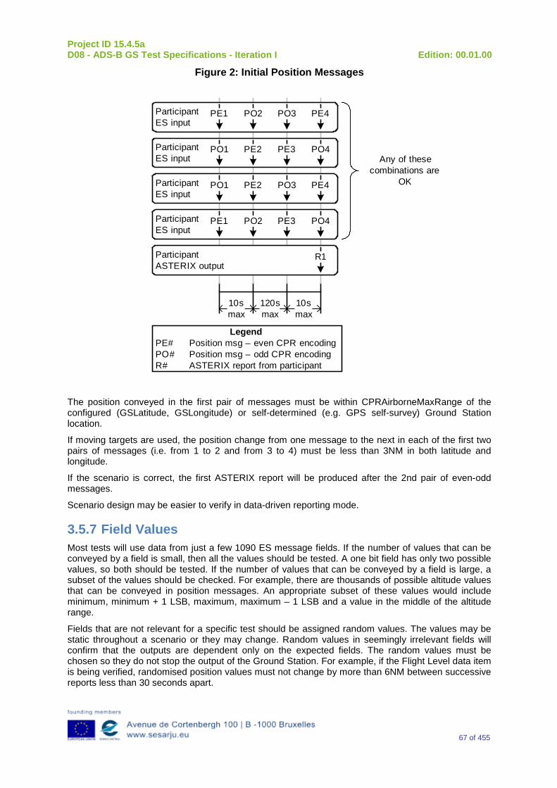
Project ID 15.4.5a D08 - ADS-B GS Test Specifications - Iteration I Edition: 00.01.00
67 of 455
Figure 2: Initial Position Messages
ParticipantASTERIX output
R1
ParticipantES input
PE1 PO2 PE3 PO4
LegendPE# Position msg – even CPR encodingPO# Position msg – odd CPR encodingR# ASTERIX report from participant
ParticipantES input
PO1 PE2 PO3 PE4
ParticipantES input
PO1 PE2 PE3 PO4
ParticipantES input
PE1 PO2 PO3 PE4
Any of these combinations are
OK
10s max
10s max
120s max
The position conveyed in the first pair of messages must be within CPRAirborneMaxRange of the configured (GSLatitude, GSLongitude) or self-determined (e.g. GPS self-survey) Ground Station location.
If moving targets are used, the position change from one message to the next in each of the first two pairs of messages (i.e. from 1 to 2 and from 3 to 4) must be less than 3NM in both latitude and longitude.
If the scenario is correct, the first ASTERIX report will be produced after the 2nd pair of even-odd messages.
Scenario design may be easier to verify in data-driven reporting mode.
3.5.7 Field Values Most tests will use data from just a few 1090 ES message fields. If the number of values that can be conveyed by a field is small, then all the values should be tested. A one bit field has only two possible values, so both should be tested. If the number of values that can be conveyed by a field is large, a subset of the values should be checked. For example, there are thousands of possible altitude values that can be conveyed in position messages. An appropriate subset of these values would include minimum, minimum + 1 LSB, maximum, maximum – 1 LSB and a value in the middle of the altitude range.
Fields that are not relevant for a specific test should be assigned random values. The values may be static throughout a scenario or they may change. Random values in seemingly irrelevant fields will confirm that the outputs are dependent only on the expected fields. The random values must be chosen so they do not stop the output of the Ground Station. For example, if the Flight Level data item is being verified, randomised position values must not change by more than 6NM between successive reports less than 30 seconds apart.
Project ID 15.4.5a D08 - ADS-B GS Test Specifications - Iteration I Edition: 00.01.00
68 of 455
3.5.8 Altitude Values Airborne position messages should contain barometric altitude unless geometric altitude is required for a specific test.
3.5.9 Configuration Changes When a specific test procedure calls for changing a 1090 ES Ground Station configuration parameter value, assume that the user will authenticate with the Ground Station, put the Ground Station in maintenance mode, change the parameter(s), put the Ground Station back into operational mode and then log out of the Ground Station. If the Ground Station was in maintenance mode or the user was already authenticated, then the mode change and authentication steps are not necessary.
3.5.10 Checking of Log Files Ground Station logs shall be checked at the conclusion of each test for unexpected warnings, errors or other anomalies. Any unexpected error or anomaly constitutes a test failure.
3.6 Integration and preliminary Verification activities
This section cannot be defined at this stage of the Project (Iteration 1): Project 15.4.5a will refine in forthcoming versions (Iteration 2 and 3) this document.
In any case, preliminary Verification activities will be limited at this stage at visual inspections of the elements that are part of the System Under Test to guarantee that it is ready to undergo the Verification activity.
Manufacturers of the Systems can define additional criteria for both the integration and preliminary activities, being the main stakeholders for the Verification activities.
3.7 Acceptance criteria This section cannot be defined at this stage of the Project (Iteration 1): Project 15.4.5a has got 2 additional Iterations which will be used to refine this document up to a concise final.
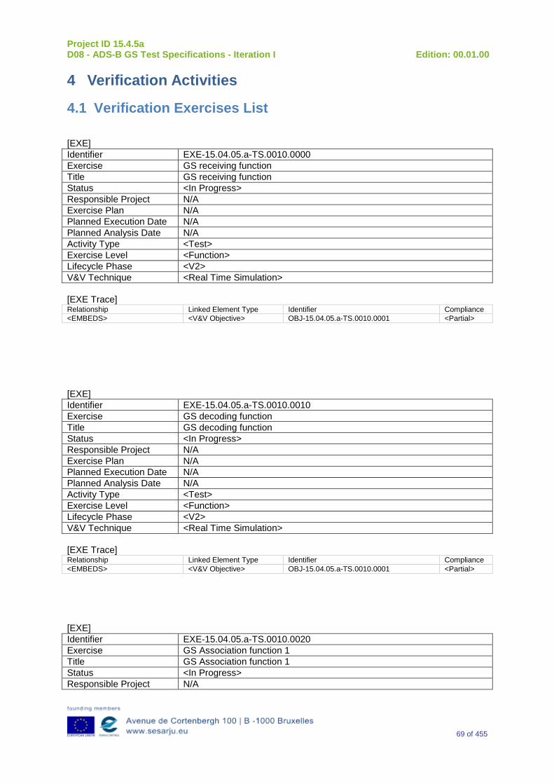
Project ID 15.4.5a D08 - ADS-B GS Test Specifications - Iteration I Edition: 00.01.00
69 of 455
4 Verification Activities
4.1 Verification Exercises List
[EXE] Identifier EXE-15.04.05.a-TS.0010.0000 Exercise GS receiving function Title GS receiving function Status <In Progress> Responsible Project N/A Exercise Plan N/A Planned Execution Date N/A Planned Analysis Date N/A Activity Type <Test> Exercise Level <Function> Lifecycle Phase <V2> V&V Technique <Real Time Simulation> [EXE Trace] Relationship Linked Element Type Identifier Compliance <EMBEDS> <V&V Objective> OBJ-15.04.05.a-TS.0010.0001 <Partial>
[EXE] Identifier EXE-15.04.05.a-TS.0010.0010 Exercise GS decoding function Title GS decoding function Status <In Progress> Responsible Project N/A Exercise Plan N/A Planned Execution Date N/A Planned Analysis Date N/A Activity Type <Test> Exercise Level <Function> Lifecycle Phase <V2> V&V Technique <Real Time Simulation> [EXE Trace] Relationship Linked Element Type Identifier Compliance <EMBEDS> <V&V Objective> OBJ-15.04.05.a-TS.0010.0001 <Partial>
[EXE] Identifier EXE-15.04.05.a-TS.0010.0020 Exercise GS Association function 1 Title GS Association function 1 Status <In Progress> Responsible Project N/A
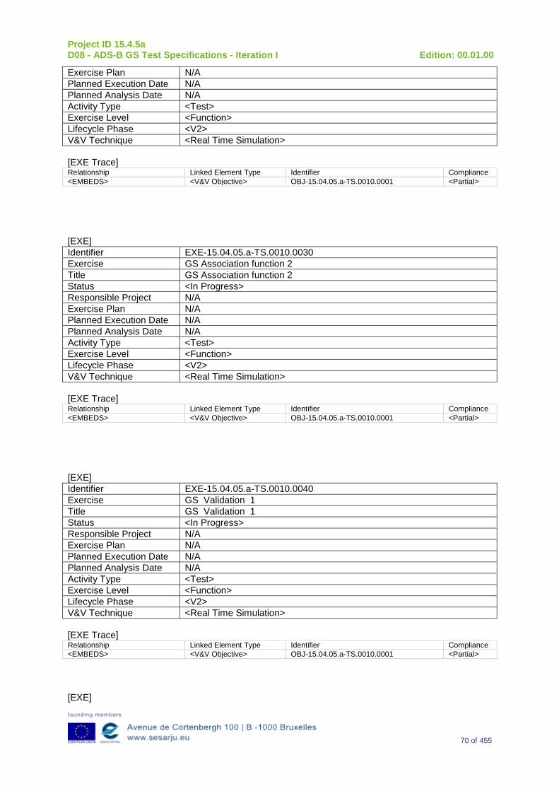
Project ID 15.4.5a D08 - ADS-B GS Test Specifications - Iteration I Edition: 00.01.00
70 of 455
Exercise Plan N/A Planned Execution Date N/A Planned Analysis Date N/A Activity Type <Test> Exercise Level <Function> Lifecycle Phase <V2> V&V Technique <Real Time Simulation> [EXE Trace] Relationship Linked Element Type Identifier Compliance <EMBEDS> <V&V Objective> OBJ-15.04.05.a-TS.0010.0001 <Partial>
[EXE] Identifier EXE-15.04.05.a-TS.0010.0030 Exercise GS Association function 2 Title GS Association function 2 Status <In Progress> Responsible Project N/A Exercise Plan N/A Planned Execution Date N/A Planned Analysis Date N/A Activity Type <Test> Exercise Level <Function> Lifecycle Phase <V2> V&V Technique <Real Time Simulation> [EXE Trace] Relationship Linked Element Type Identifier Compliance <EMBEDS> <V&V Objective> OBJ-15.04.05.a-TS.0010.0001 <Partial>
[EXE] Identifier EXE-15.04.05.a-TS.0010.0040 Exercise GS Validation 1 Title GS Validation 1 Status <In Progress> Responsible Project N/A Exercise Plan N/A Planned Execution Date N/A Planned Analysis Date N/A Activity Type <Test> Exercise Level <Function> Lifecycle Phase <V2> V&V Technique <Real Time Simulation> [EXE Trace] Relationship Linked Element Type Identifier Compliance <EMBEDS> <V&V Objective> OBJ-15.04.05.a-TS.0010.0001 <Partial>
[EXE]
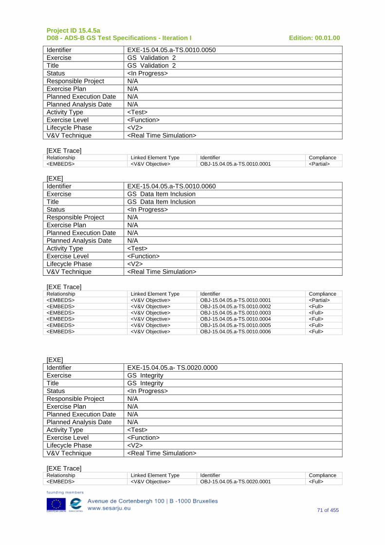
Project ID 15.4.5a D08 - ADS-B GS Test Specifications - Iteration I Edition: 00.01.00
71 of 455
Identifier EXE-15.04.05.a-TS.0010.0050 Exercise GS Validation 2 Title GS Validation 2 Status <In Progress> Responsible Project N/A Exercise Plan N/A Planned Execution Date N/A Planned Analysis Date N/A Activity Type <Test> Exercise Level <Function> Lifecycle Phase <V2> V&V Technique <Real Time Simulation> [EXE Trace] Relationship Linked Element Type Identifier Compliance <EMBEDS> <V&V Objective> OBJ-15.04.05.a-TS.0010.0001 <Partial> [EXE] Identifier EXE-15.04.05.a-TS.0010.0060 Exercise GS Data Item Inclusion Title GS Data Item Inclusion Status <In Progress> Responsible Project N/A Exercise Plan N/A Planned Execution Date N/A Planned Analysis Date N/A Activity Type <Test> Exercise Level <Function> Lifecycle Phase <V2> V&V Technique <Real Time Simulation> [EXE Trace] Relationship Linked Element Type Identifier Compliance <EMBEDS> <V&V Objective> OBJ-15.04.05.a-TS.0010.0001 <Partial> <EMBEDS> <V&V Objective> OBJ-15.04.05.a-TS.0010.0002 <Full> <EMBEDS> <V&V Objective> OBJ-15.04.05.a-TS.0010.0003 <Full> <EMBEDS> <V&V Objective> OBJ-15.04.05.a-TS.0010.0004 <Full> <EMBEDS> <V&V Objective> OBJ-15.04.05.a-TS.0010.0005 <Full> <EMBEDS> <V&V Objective> OBJ-15.04.05.a-TS.0010.0006 <Full>
[EXE] Identifier EXE-15.04.05.a- TS.0020.0000 Exercise GS Integrity Title GS Integrity Status <In Progress> Responsible Project N/A Exercise Plan N/A Planned Execution Date N/A Planned Analysis Date N/A Activity Type <Test> Exercise Level <Function> Lifecycle Phase <V2> V&V Technique <Real Time Simulation> [EXE Trace] Relationship Linked Element Type Identifier Compliance <EMBEDS> <V&V Objective> OBJ-15.04.05.a-TS.0020.0001 <Full>
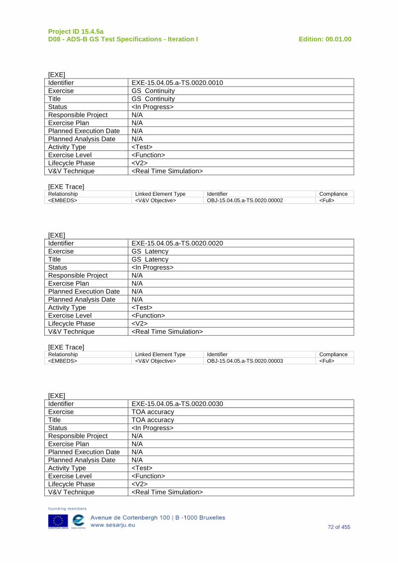
Project ID 15.4.5a D08 - ADS-B GS Test Specifications - Iteration I Edition: 00.01.00
72 of 455
[EXE] Identifier EXE-15.04.05.a-TS.0020.0010 Exercise GS Continuity Title GS Continuity Status <In Progress> Responsible Project N/A Exercise Plan N/A Planned Execution Date N/A Planned Analysis Date N/A Activity Type <Test> Exercise Level <Function> Lifecycle Phase <V2> V&V Technique <Real Time Simulation> [EXE Trace] Relationship Linked Element Type Identifier Compliance <EMBEDS> <V&V Objective> OBJ-15.04.05.a-TS.0020.00002 <Full>
[EXE] Identifier EXE-15.04.05.a-TS.0020.0020 Exercise GS Latency Title GS Latency Status <In Progress> Responsible Project N/A Exercise Plan N/A Planned Execution Date N/A Planned Analysis Date N/A Activity Type <Test> Exercise Level <Function> Lifecycle Phase <V2> V&V Technique <Real Time Simulation> [EXE Trace] Relationship Linked Element Type Identifier Compliance <EMBEDS> <V&V Objective> OBJ-15.04.05.a-TS.0020.00003 <Full>
[EXE] Identifier EXE-15.04.05.a-TS.0020.0030 Exercise TOA accuracy Title TOA accuracy Status <In Progress> Responsible Project N/A Exercise Plan N/A Planned Execution Date N/A Planned Analysis Date N/A Activity Type <Test> Exercise Level <Function> Lifecycle Phase <V2> V&V Technique <Real Time Simulation>
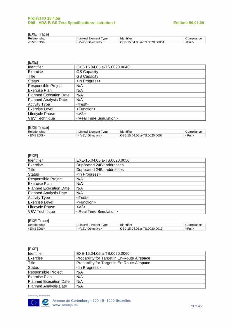
Project ID 15.4.5a D08 - ADS-B GS Test Specifications - Iteration I Edition: 00.01.00
73 of 455
[EXE Trace] Relationship Linked Element Type Identifier Compliance <EMBEDS> <V&V Objective> OBJ-15.04.05.a-TS.0020.00004 <Full>
[EXE] Identifier EXE-15.04.05.a-TS.0020.0040 Exercise GS Capacity Title GS Capacity Status <In Progress> Responsible Project N/A Exercise Plan N/A Planned Execution Date N/A Planned Analysis Date N/A Activity Type <Test> Exercise Level <Function> Lifecycle Phase <V2> V&V Technique <Real Time Simulation> [EXE Trace] Relationship Linked Element Type Identifier Compliance <EMBEDS> <V&V Objective> OBJ-15.04.05.a-TS.0020.0007 <Full>
[EXE] Identifier EXE-15.04.05.a-TS.0020.0050 Exercise Duplicated 24Bit addresses Title Duplicated 24Bit addresses Status <In Progress> Responsible Project N/A Exercise Plan N/A Planned Execution Date N/A Planned Analysis Date N/A Activity Type <Test> Exercise Level <Function> Lifecycle Phase <V2> V&V Technique <Real Time Simulation> [EXE Trace] Relationship Linked Element Type Identifier Compliance <EMBEDS> <V&V Objective> OBJ-15.04.05.a-TS.0020.0013 <Full>
[EXE] Identifier EXE-15.04.05.a-TS.0020.0060 Exercise Probability for Target in En-Route Airspace Title Probability for Target in En-Route Airspace Status <In Progress> Responsible Project N/A Exercise Plan N/A Planned Execution Date N/A Planned Analysis Date N/A
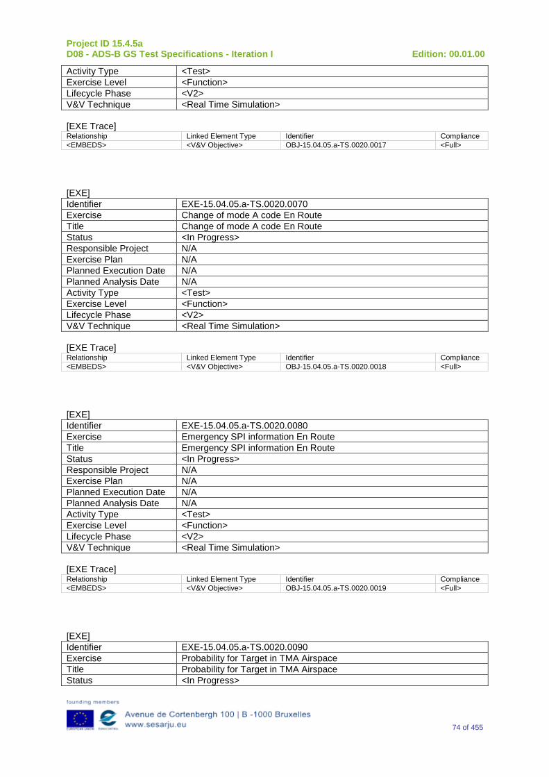
Project ID 15.4.5a D08 - ADS-B GS Test Specifications - Iteration I Edition: 00.01.00
74 of 455
Activity Type <Test> Exercise Level <Function> Lifecycle Phase <V2> V&V Technique <Real Time Simulation> [EXE Trace] Relationship Linked Element Type Identifier Compliance <EMBEDS> <V&V Objective> OBJ-15.04.05.a-TS.0020.0017 <Full>
[EXE] Identifier EXE-15.04.05.a-TS.0020.0070 Exercise Change of mode A code En Route Title Change of mode A code En Route Status <In Progress> Responsible Project N/A Exercise Plan N/A Planned Execution Date N/A Planned Analysis Date N/A Activity Type <Test> Exercise Level <Function> Lifecycle Phase <V2> V&V Technique <Real Time Simulation> [EXE Trace] Relationship Linked Element Type Identifier Compliance <EMBEDS> <V&V Objective> OBJ-15.04.05.a-TS.0020.0018 <Full>
[EXE] Identifier EXE-15.04.05.a-TS.0020.0080 Exercise Emergency SPI information En Route Title Emergency SPI information En Route Status <In Progress> Responsible Project N/A Exercise Plan N/A Planned Execution Date N/A Planned Analysis Date N/A Activity Type <Test> Exercise Level <Function> Lifecycle Phase <V2> V&V Technique <Real Time Simulation> [EXE Trace] Relationship Linked Element Type Identifier Compliance <EMBEDS> <V&V Objective> OBJ-15.04.05.a-TS.0020.0019 <Full>
[EXE] Identifier EXE-15.04.05.a-TS.0020.0090 Exercise Probability for Target in TMA Airspace Title Probability for Target in TMA Airspace Status <In Progress>
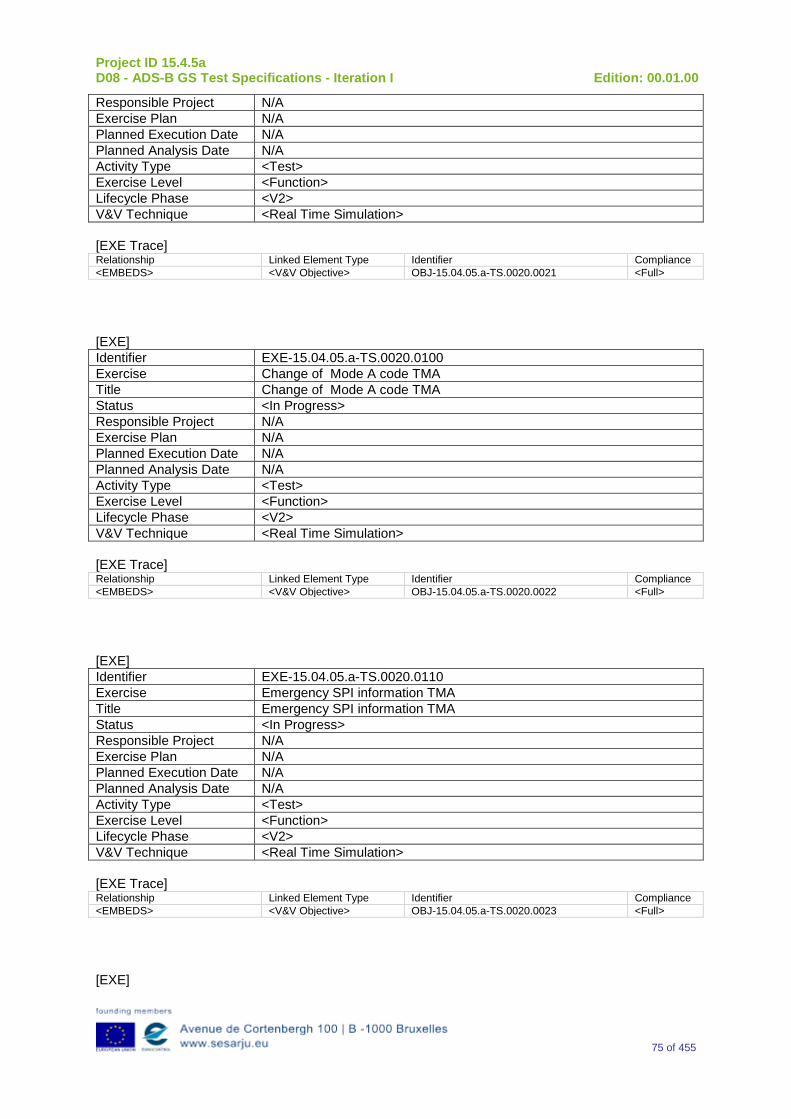
Project ID 15.4.5a D08 - ADS-B GS Test Specifications - Iteration I Edition: 00.01.00
75 of 455
Responsible Project N/A Exercise Plan N/A Planned Execution Date N/A Planned Analysis Date N/A Activity Type <Test> Exercise Level <Function> Lifecycle Phase <V2> V&V Technique <Real Time Simulation> [EXE Trace] Relationship Linked Element Type Identifier Compliance <EMBEDS> <V&V Objective> OBJ-15.04.05.a-TS.0020.0021 <Full>
[EXE] Identifier EXE-15.04.05.a-TS.0020.0100 Exercise Change of Mode A code TMA Title Change of Mode A code TMA Status <In Progress> Responsible Project N/A Exercise Plan N/A Planned Execution Date N/A Planned Analysis Date N/A Activity Type <Test> Exercise Level <Function> Lifecycle Phase <V2> V&V Technique <Real Time Simulation> [EXE Trace] Relationship Linked Element Type Identifier Compliance <EMBEDS> <V&V Objective> OBJ-15.04.05.a-TS.0020.0022 <Full>
[EXE] Identifier EXE-15.04.05.a-TS.0020.0110 Exercise Emergency SPI information TMA Title Emergency SPI information TMA Status <In Progress> Responsible Project N/A Exercise Plan N/A Planned Execution Date N/A Planned Analysis Date N/A Activity Type <Test> Exercise Level <Function> Lifecycle Phase <V2> V&V Technique <Real Time Simulation> [EXE Trace] Relationship Linked Element Type Identifier Compliance <EMBEDS> <V&V Objective> OBJ-15.04.05.a-TS.0020.0023 <Full>
[EXE]
Project ID 15.4.5a D08 - ADS-B GS Test Specifications - Iteration I Edition: 00.01.00
76 of 455
Identifier EXE-15.04.05.a-TS.0030.0010 Exercise Integration with WAM Title Integration with WAM Status <In Progress> Responsible Project N/A Exercise Plan N/A Planned Execution Date N/A Planned Analysis Date N/A Activity Type <Test> Exercise Level <Function> Lifecycle Phase <V2> V&V Technique <Real Time Simulation> [EXE Trace] Relationship Linked Element Type Identifier Compliance <EMBEDS> <V&V Objective> OBJ-15.04.05.a-TS.0030.0001 <Full> <EMBEDS> <V&V Objective> OBJ-15.04.05.a-TS.0030.0002 <Full> <EMBEDS> <V&V Objective> OBJ-15.04.05.a-TS.0030.0003 <Full> <EMBEDS> <V&V Objective> OBJ-15.04.05.a-TS.0030.0004 <Full> <EMBEDS> <V&V Objective> OBJ-15.04.05.a-TS.0030.0005 <Full> <EMBEDS> <V&V Objective> OBJ-15.04.05.a-TS.0030.0006 <Full> <EMBEDS> <V&V Objective> OBJ-15.04.05.a-TS.0030.0007 <Full> <EMBEDS> <V&V Objective> OBJ-15.04.05.a-TS.0030.0008 <Full>
[EXE] Identifier EXE-15.04.05.a-TS.0040.0000 Exercise Angle of Arrival Validation Title Angle of Arrival Validation Status <In Progress> Responsible Project N/A Exercise Plan N/A Planned Execution Date N/A Planned Analysis Date N/A Activity Type <Test> Exercise Level <Function> Lifecycle Phase <V2> V&V Technique <Real Time Simulation> [EXE Trace] Relationship Linked Element Type Identifier Compliance <EMBEDS> <V&V Objective> OBJ-15.04.05.a-TS.0040.0001 <Full> <EMBEDS> <V&V Objective> OBJ-15.04.05.a-TS.0040.0002 <Full> <EMBEDS> <V&V Objective> OBJ-15.04.05.a-TS.0040.0003 <Full> <EMBEDS> <V&V Objective> OBJ-15.04.05.a-TS.0040.0004 <Full> <EMBEDS> <V&V Objective> OBJ-15.04.05.a-TS.0040.0005 <Full> <EMBEDS> <V&V Objective> OBJ-15.04.05.a-TS.0040.0006 <Full> <EMBEDS> <V&V Objective> OBJ-15.04.05.a-TS.0040.0007 <Full>
[EXE] Identifier EXE-15.04.05.a-TS.0040.0020 Exercise Power versus Distance Validation Title Power versus Distance Validation Status <In Progress>
Project ID 15.4.5a D08 - ADS-B GS Test Specifications - Iteration I Edition: 00.01.00
77 of 455
Responsible Project N/A Exercise Plan N/A Planned Execution Date N/A Planned Analysis Date N/A Activity Type <Test> Exercise Level <Function> Lifecycle Phase <V2> V&V Technique <Real Time Simulation> [EXE Trace] Relationship Linked Element Type Identifier Compliance <EMBEDS> <V&V Objective> OBJ-15.04.05.a-TS.0040.0040 <Full> <EMBEDS> <V&V Objective> OBJ-15.04.05.a-TS.0040.0041 <Full> <EMBEDS> <V&V Objective> OBJ-15.04.05.a-TS.0040.0042 <Full> <EMBEDS> <V&V Objective> OBJ-15.04.05.a-TS.0040.0043 <Full> <EMBEDS> <V&V Objective> OBJ-15.04.05.a-TS.0040.0044 <Full> <EMBEDS> <V&V Objective> OBJ-15.04.05.a-TS.0040.0045 <Full> <EMBEDS> <V&V Objective> OBJ-15.04.05.a-TS.0040.0046 <Full> <EMBEDS> <V&V Objective> OBJ-15.04.05.a-TS.0040.0047 <Full>
[EXE] Identifier EXE-15.04.05.a-TS.0040.0030 Exercise Time of Arrival versus Distance Validation Title Time of Arrival versus Distance Validation Status <In Progress> Responsible Project N/A Exercise Plan N/A Planned Execution Date N/A Planned Analysis Date N/A Activity Type <Test> Exercise Level <Function> Lifecycle Phase <V2> V&V Technique <Real Time Simulation> [EXE Trace] Relationship Linked Element Type Identifier Compliance <EMBEDS> <V&V Objective> OBJ-15.04.05.a-TS.0040.0030 <Full> <EMBEDS> <V&V Objective> OBJ-15.04.05.a-TS.0040.0031 <Full> <EMBEDS> <V&V Objective> OBJ-15.04.05.a-TS.0040.0032 <Full> <EMBEDS> <V&V Objective> OBJ-15.04.05.a-TS.0040.0033 <Full>
[EXE] Identifier EXE-15.04.05.a-TS.0060.0000 Exercise “Reserved” OM Code Subfield in Aircraft Operational Status Messages Title “Reserved” OM Code Subfield in Aircraft Operational Status Messages Status <In Progress> Responsible Project N/A Exercise Plan N/A Planned Execution Date N/A Planned Analysis Date N/A Activity Type <Test> Exercise Level <Function> Lifecycle Phase <V2> V&V Technique <Real Time Simulation>
Project ID 15.4.5a D08 - ADS-B GS Test Specifications - Iteration I Edition: 00.01.00
78 of 455
[EXE Trace] Relationship Linked Element Type Identifier Compliance <EMBEDS> <V&V Objective> OBJ-15.04.05.a-TS.0060.0061 <Partial> <EMBEDS> <V&V Objective> OBJ-15.04.05.a-TS.0060.0063 <Partial>
[EXE] Identifier EXE-15.04.05.a-TS.0060.0010 Exercise Reserved Bit-A” Subfield in Airborne Velocity Messages – Subtype=1 Title Reserved Bit-A” Subfield in Airborne Velocity Messages – Subtype=1 Status <In Progress> Responsible Project N/A Exercise Plan N/A Planned Execution Date N/A Planned Analysis Date N/A Activity Type <Test> Exercise Level <Function> Lifecycle Phase <V2> V&V Technique <Real Time Simulation> [EXE Trace] Relationship Linked Element Type Identifier Compliance <EMBEDS> <V&V Objective> OBJ-15.04.05.a-TS.0060.0061 <Partial> <EMBEDS> <V&V Objective> OBJ-15.04.05.a-TS.0060.0063 <Partial>
[EXE] Identifier EXE-15.04.05.a-TS.0060.0020 Exercise TCAS Operational” Subfield in Target State and Status Messages Title TCAS Operational” Subfield in Target State and Status Messages Status <In Progress> Responsible Project N/A Exercise Plan N/A Planned Execution Date N/A Planned Analysis Date N/A Activity Type <Test> Exercise Level <Function> Lifecycle Phase <V2> V&V Technique <Real Time Simulation> [EXE Trace] Relationship Linked Element Type Identifier Compliance <EMBEDS> <V&V Objective> OBJ-15.04.05.a-TS.0060.0061 <Partial> <EMBEDS> <V&V Objective> OBJ-15.04.05.a-TS.0060.0063 <Partial>
[EXE] Identifier EXE-15.04.05.a-TS.0060.0030 Exercise “Geometric Vertical Accuracy (GVA)” Subfield in Aircraft Operational
Status Messages Title “Geometric Vertical Accuracy (GVA)” Subfield in Aircraft Operational
Status Messages Status <In Progress>
Project ID 15.4.5a D08 - ADS-B GS Test Specifications - Iteration I Edition: 00.01.00
79 of 455
Responsible Project N/A Exercise Plan N/A Planned Execution Date N/A Planned Analysis Date N/A Activity Type <Test> Exercise Level <Function> Lifecycle Phase <V2> V&V Technique <Real Time Simulation> [EXE Trace] Relationship Linked Element Type Identifier Compliance <EMBEDS> <V&V Objective> OBJ-15.04.05.a-TS.0060.0061 <Partial> <EMBEDS> <V&V Objective> OBJ-15.04.05.a-TS.0060.0063 <Partial>
[EXE] Identifier EXE-15.04.05.a-TS.0060.0040 Exercise GPS Antenna Offset” OM Code Subfield in Aircraft Operational Status
Messages Title GPS Antenna Offset” OM Code Subfield in Aircraft Operational Status
Messages Status <In Progress> Responsible Project N/A Exercise Plan N/A Planned Execution Date N/A Planned Analysis Date N/A Activity Type <Test> Exercise Level <Function> Lifecycle Phase <V2> V&V Technique <Real Time Simulation> [EXE Trace] Relationship Linked Element Type Identifier Compliance <EMBEDS> <V&V Objective> OBJ-15.04.05.a-TS.0060.0063 <Partial> <EMBEDS> <V&V Objective> OBJ-15.04.05.a-TS.0060.0061 <Partial>
[EXE] Identifier EXE-15.04.05.a-TS.0060.0050 Exercise Source Integrity Level (SIL)” Subfield in Aircraft Operational Status
Messages Title Source Integrity Level (SIL)” Subfield in Aircraft Operational Status
Messages Status <In Progress> Responsible Project N/A Exercise Plan N/A Planned Execution Date N/A Planned Analysis Date N/A Activity Type <Test> Exercise Level <Function> Lifecycle Phase <V2> V&V Technique <Real Time Simulation> [EXE Trace] Relationship Linked Element Type Identifier Compliance
Project ID 15.4.5a D08 - ADS-B GS Test Specifications - Iteration I Edition: 00.01.00
80 of 455
<EMBEDS> <V&V Objective> OBJ-15.04.05.a-TS.0060.0063 <Partial> <EMBEDS> <V&V Objective> OBJ-15.04.05.a-TS.0060.0061 <Partial>
[EXE] Identifier EXE-15.04.05.a-TS.0060.0060 Exercise “SIL Supplement” Subfield in Aircraft Operational Status Messages Title “SIL Supplement” Subfield in Aircraft Operational Status Messages Status <In Progress> Responsible Project N/A Exercise Plan N/A Planned Execution Date N/A Planned Analysis Date N/A Activity Type <Test> Exercise Level <Function> Lifecycle Phase <V2> V&V Technique <Real Time Simulation> [EXE Trace] Relationship Linked Element Type Identifier Compliance <EMBEDS> <V&V Objective> OBJ-15.04.05.a-TS.0060.0063 <Partial> <EMBEDS> <V&V Objective> OBJ-15.04.05.a-TS.0060.0061 <Partial>
[EXE] Identifier EXE-15.04.05.a-TS.0060.0070 Exercise “System Design Assurance” OM Code Subfield in Aircraft Operational
Status Messages Title “System Design Assurance” OM Code Subfield in Aircraft Operational
Status Messages Status <In Progress> Responsible Project N/A Exercise Plan N/A Planned Execution Date N/A Planned Analysis Date N/A Activity Type <Test> Exercise Level <Function> Lifecycle Phase <V2> V&V Technique <Real Time Simulation> [EXE Trace] Relationship Linked Element Type Identifier Compliance <EMBEDS> <V&V Objective> OBJ-15.04.05.a-TS.0060.0063 <Partial> <EMBEDS> <V&V Objective> OBJ-15.04.05.a-TS.0060.0061 <Partial>
[EXE] Identifier EXE-15.04.05.a-TS.0060.0080 Exercise “1090ES IN” CC Code Subfield in Aircraft Operational Status Messages Title “1090ES IN” CC Code Subfield in Aircraft Operational Status Messages Status <In Progress> Responsible Project N/A Exercise Plan N/A
Project ID 15.4.5a D08 - ADS-B GS Test Specifications - Iteration I Edition: 00.01.00
81 of 455
Planned Execution Date N/A Planned Analysis Date N/A Activity Type <Test> Exercise Level <Function> Lifecycle Phase <V2> V&V Technique <Real Time Simulation> [EXE Trace] Relationship Linked Element Type Identifier Compliance <EMBEDS> <V&V Objective> OBJ-15.04.05.a-TS.0060.0063 <Partial> <EMBEDS> <V&V Objective> OBJ-15.04.05.a-TS.0060.0061 <Partial>
[EXE] Identifier EXE-15.04.05.a-TS.0060.0090 Exercise “UAT IN” CC Code Subfield in Aircraft Operational Status Messages Title “UAT IN” CC Code Subfield in Aircraft Operational Status Messages Status <In Progress> Responsible Project N/A Exercise Plan N/A Planned Execution Date N/A Planned Analysis Date N/A Activity Type <Test> Exercise Level <Function> Lifecycle Phase <V2> V&V Technique <Real Time Simulation> [EXE Trace] Relationship Linked Element Type Identifier Compliance <EMBEDS> <V&V Objective> OBJ-15.04.05.a-TS.0060.0063 <Partial> <EMBEDS> <V&V Objective> OBJ-15.04.05.a-TS.0060.0061 <Partial>
[EXE] Identifier EXE-15.04.05.a-TS.0060.0100 Exercise “NIC Supplement-B” Subfield in ADS-B Airborne Position Messages Title “NIC Supplement-B” Subfield in ADS-B Airborne Position Messages Status <In Progress> Responsible Project N/A Exercise Plan N/A Planned Execution Date N/A Planned Analysis Date N/A Activity Type <Test> Exercise Level <Function> Lifecycle Phase <V2> V&V Technique <Real Time Simulation> [EXE Trace] Relationship Linked Element Type Identifier Compliance <EMBEDS> <V&V Objective> OBJ-15.04.05.a-TS.0060.0063 <Partial> <EMBEDS> <V&V Objective> OBJ-15.04.05.a-TS.0060.0061 <Partial>
[EXE]
Project ID 15.4.5a D08 - ADS-B GS Test Specifications - Iteration I Edition: 00.01.00
82 of 455
Identifier EXE-15.04.05.a-TS.0060.0110 Exercise “NIC Supplement-C” Subfield in Aircraft Operational Status Messages Title “NIC Supplement-C” Subfield in Aircraft Operational Status Messages Status <In Progress> Responsible Project N/A Exercise Plan N/A Planned Execution Date N/A Planned Analysis Date N/A Activity Type <Test> Exercise Level <Function> Lifecycle Phase <V2> V&V Technique <Real Time Simulation> [EXE Trace] Relationship Linked Element Type Identifier Compliance <EMBEDS> <V&V Objective> OBJ-15.04.05.a-TS.0060.0063 <Partial> <EMBEDS> <V&V Objective> OBJ-15.04.05.a-TS.0060.0061 <Partial>
[EXE] Identifier EXE-15.04.05.a-TS.0060.0120 Exercise “Aircraft/Vehicle Length and Width Code” Subfield in Aircraft Operational
Status Messages Title “Aircraft/Vehicle Length and Width Code” Subfield in Aircraft Operational
Status Messages Status <In Progress> Responsible Project N/A Exercise Plan N/A Planned Execution Date N/A Planned Analysis Date N/A Activity Type <Test> Exercise Level <Function> Lifecycle Phase <V2> V&V Technique <Real Time Simulation> [EXE Trace] Relationship Linked Element Type Identifier Compliance <EMBEDS> <V&V Objective> OBJ-15.04.05.a-TS.0060.0063 <Partial> <EMBEDS> <V&V Objective> OBJ-15.04.05.a-TS.0060.0061 <Partial>
[EXE] Identifier EXE-15.04.05.a-TS.0060.0130 Exercise Navigation Integrity Code (NIC) Title Navigation Integrity Code (NIC) Status <In Progress> Responsible Project N/A Exercise Plan N/A Planned Execution Date N/A Planned Analysis Date N/A Activity Type <Test> Exercise Level <Function> Lifecycle Phase <V2> V&V Technique <Real Time Simulation>
Project ID 15.4.5a D08 - ADS-B GS Test Specifications - Iteration I Edition: 00.01.00
83 of 455
[EXE Trace] Relationship Linked Element Type Identifier Compliance <EMBEDS> <V&V Objective> OBJ-15.04.05.a-TS.0060.0063 <Partial> <EMBEDS> <V&V Objective> OBJ-15.04.05.a-TS.0060.0061 <Partial>
[EXE] Identifier EXE-15.04.05.a-TS.0060.0140 Exercise “NACP” Subfield in Target State and Status Messages Title “NACP” Subfield in Target State and Status Messages Status <In Progress> Responsible Project N/A Exercise Plan N/A Planned Execution Date N/A Planned Analysis Date N/A Activity Type <Test> Exercise Level <Function> Lifecycle Phase <V2> V&V Technique <Real Time Simulation> [EXE Trace] Relationship Linked Element Type Identifier Compliance <EMBEDS> <V&V Objective> OBJ-15.04.05.a-TS.0060.0063 <Partial> <EMBEDS> <V&V Objective> OBJ-15.04.05.a-TS.0060.0061 <Partial>
[EXE] Identifier EXE-15.04.05.a-TS.0060.0150 Exercise “NACV” Subfield in Airborne Velocity Messages - Subtype=1 Title “NACV” Subfield in Airborne Velocity Messages - Subtype=1 Status <In Progress> Responsible Project N/A Exercise Plan N/A Planned Execution Date N/A Planned Analysis Date N/A Activity Type <Test> Exercise Level <Function> Lifecycle Phase <V2> V&V Technique <Real Time Simulation> [EXE Trace] Relationship Linked Element Type Identifier Compliance <EMBEDS> <V&V Objective> OBJ-15.04.05.a-TS.0060.0063 <Partial> <EMBEDS> <V&V Objective> OBJ-15.04.05.a-TS.0060.0061 <Partial>
[EXE] Identifier EXE-15.04.05.a-TS.0060.0160 Exercise “Selected Heading Status”, “Selected Heading Sign”, and “Selected
Heading” Title “Selected Heading Status”, “Selected Heading Sign”, and “Selected
Heading” Status <In Progress>
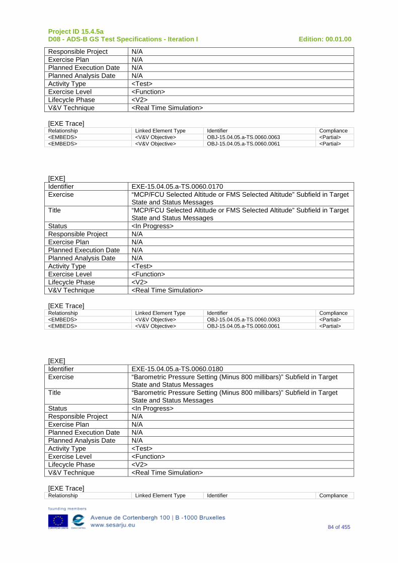
Project ID 15.4.5a D08 - ADS-B GS Test Specifications - Iteration I Edition: 00.01.00
84 of 455
Responsible Project N/A Exercise Plan N/A Planned Execution Date N/A Planned Analysis Date N/A Activity Type <Test> Exercise Level <Function> Lifecycle Phase <V2> V&V Technique <Real Time Simulation> [EXE Trace] Relationship Linked Element Type Identifier Compliance <EMBEDS> <V&V Objective> OBJ-15.04.05.a-TS.0060.0063 <Partial> <EMBEDS> <V&V Objective> OBJ-15.04.05.a-TS.0060.0061 <Partial>
[EXE] Identifier EXE-15.04.05.a-TS.0060.0170 Exercise “MCP/FCU Selected Altitude or FMS Selected Altitude” Subfield in Target
State and Status Messages Title “MCP/FCU Selected Altitude or FMS Selected Altitude” Subfield in Target
State and Status Messages Status <In Progress> Responsible Project N/A Exercise Plan N/A Planned Execution Date N/A Planned Analysis Date N/A Activity Type <Test> Exercise Level <Function> Lifecycle Phase <V2> V&V Technique <Real Time Simulation> [EXE Trace] Relationship Linked Element Type Identifier Compliance <EMBEDS> <V&V Objective> OBJ-15.04.05.a-TS.0060.0063 <Partial> <EMBEDS> <V&V Objective> OBJ-15.04.05.a-TS.0060.0061 <Partial>
[EXE] Identifier EXE-15.04.05.a-TS.0060.0180 Exercise “Barometric Pressure Setting (Minus 800 millibars)” Subfield in Target
State and Status Messages Title “Barometric Pressure Setting (Minus 800 millibars)” Subfield in Target
State and Status Messages Status <In Progress> Responsible Project N/A Exercise Plan N/A Planned Execution Date N/A Planned Analysis Date N/A Activity Type <Test> Exercise Level <Function> Lifecycle Phase <V2> V&V Technique <Real Time Simulation> [EXE Trace] Relationship Linked Element Type Identifier Compliance
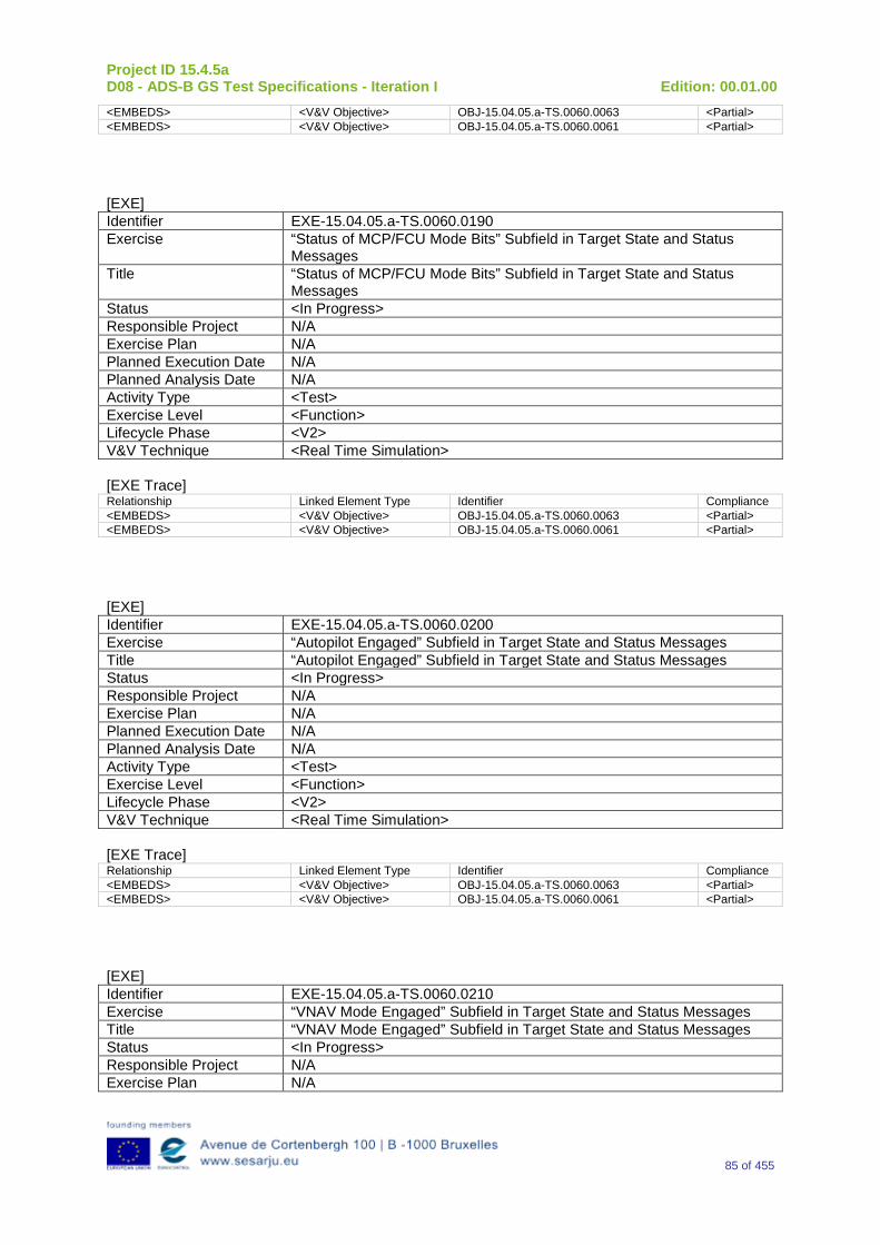
Project ID 15.4.5a D08 - ADS-B GS Test Specifications - Iteration I Edition: 00.01.00
85 of 455
<EMBEDS> <V&V Objective> OBJ-15.04.05.a-TS.0060.0063 <Partial> <EMBEDS> <V&V Objective> OBJ-15.04.05.a-TS.0060.0061 <Partial>
[EXE] Identifier EXE-15.04.05.a-TS.0060.0190 Exercise “Status of MCP/FCU Mode Bits” Subfield in Target State and Status
Messages Title “Status of MCP/FCU Mode Bits” Subfield in Target State and Status
Messages Status <In Progress> Responsible Project N/A Exercise Plan N/A Planned Execution Date N/A Planned Analysis Date N/A Activity Type <Test> Exercise Level <Function> Lifecycle Phase <V2> V&V Technique <Real Time Simulation> [EXE Trace] Relationship Linked Element Type Identifier Compliance <EMBEDS> <V&V Objective> OBJ-15.04.05.a-TS.0060.0063 <Partial> <EMBEDS> <V&V Objective> OBJ-15.04.05.a-TS.0060.0061 <Partial>
[EXE] Identifier EXE-15.04.05.a-TS.0060.0200 Exercise “Autopilot Engaged” Subfield in Target State and Status Messages Title “Autopilot Engaged” Subfield in Target State and Status Messages Status <In Progress> Responsible Project N/A Exercise Plan N/A Planned Execution Date N/A Planned Analysis Date N/A Activity Type <Test> Exercise Level <Function> Lifecycle Phase <V2> V&V Technique <Real Time Simulation> [EXE Trace] Relationship Linked Element Type Identifier Compliance <EMBEDS> <V&V Objective> OBJ-15.04.05.a-TS.0060.0063 <Partial> <EMBEDS> <V&V Objective> OBJ-15.04.05.a-TS.0060.0061 <Partial>
[EXE] Identifier EXE-15.04.05.a-TS.0060.0210 Exercise “VNAV Mode Engaged” Subfield in Target State and Status Messages Title “VNAV Mode Engaged” Subfield in Target State and Status Messages Status <In Progress> Responsible Project N/A Exercise Plan N/A
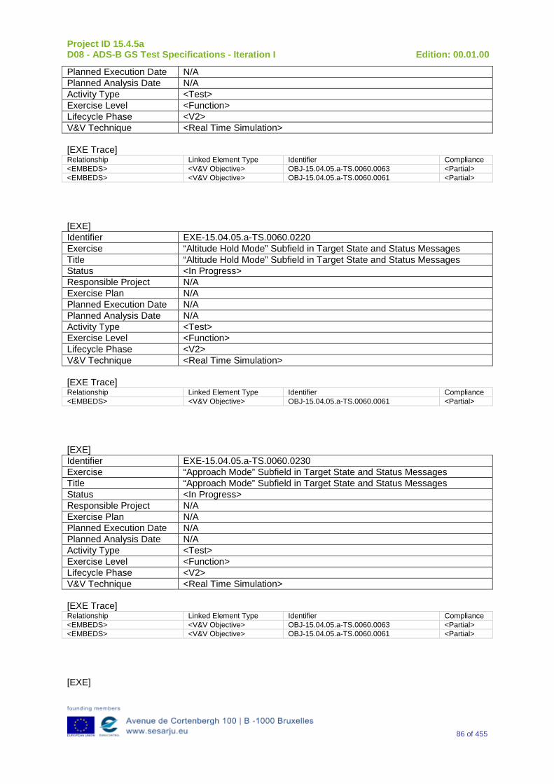
Project ID 15.4.5a D08 - ADS-B GS Test Specifications - Iteration I Edition: 00.01.00
86 of 455
Planned Execution Date N/A Planned Analysis Date N/A Activity Type <Test> Exercise Level <Function> Lifecycle Phase <V2> V&V Technique <Real Time Simulation> [EXE Trace] Relationship Linked Element Type Identifier Compliance <EMBEDS> <V&V Objective> OBJ-15.04.05.a-TS.0060.0063 <Partial> <EMBEDS> <V&V Objective> OBJ-15.04.05.a-TS.0060.0061 <Partial>
[EXE] Identifier EXE-15.04.05.a-TS.0060.0220 Exercise “Altitude Hold Mode” Subfield in Target State and Status Messages Title “Altitude Hold Mode” Subfield in Target State and Status Messages Status <In Progress> Responsible Project N/A Exercise Plan N/A Planned Execution Date N/A Planned Analysis Date N/A Activity Type <Test> Exercise Level <Function> Lifecycle Phase <V2> V&V Technique <Real Time Simulation> [EXE Trace] Relationship Linked Element Type Identifier Compliance <EMBEDS> <V&V Objective> OBJ-15.04.05.a-TS.0060.0061 <Partial>
[EXE] Identifier EXE-15.04.05.a-TS.0060.0230 Exercise “Approach Mode” Subfield in Target State and Status Messages Title “Approach Mode” Subfield in Target State and Status Messages Status <In Progress> Responsible Project N/A Exercise Plan N/A Planned Execution Date N/A Planned Analysis Date N/A Activity Type <Test> Exercise Level <Function> Lifecycle Phase <V2> V&V Technique <Real Time Simulation> [EXE Trace] Relationship Linked Element Type Identifier Compliance <EMBEDS> <V&V Objective> OBJ-15.04.05.a-TS.0060.0063 <Partial> <EMBEDS> <V&V Objective> OBJ-15.04.05.a-TS.0060.0061 <Partial>
[EXE]
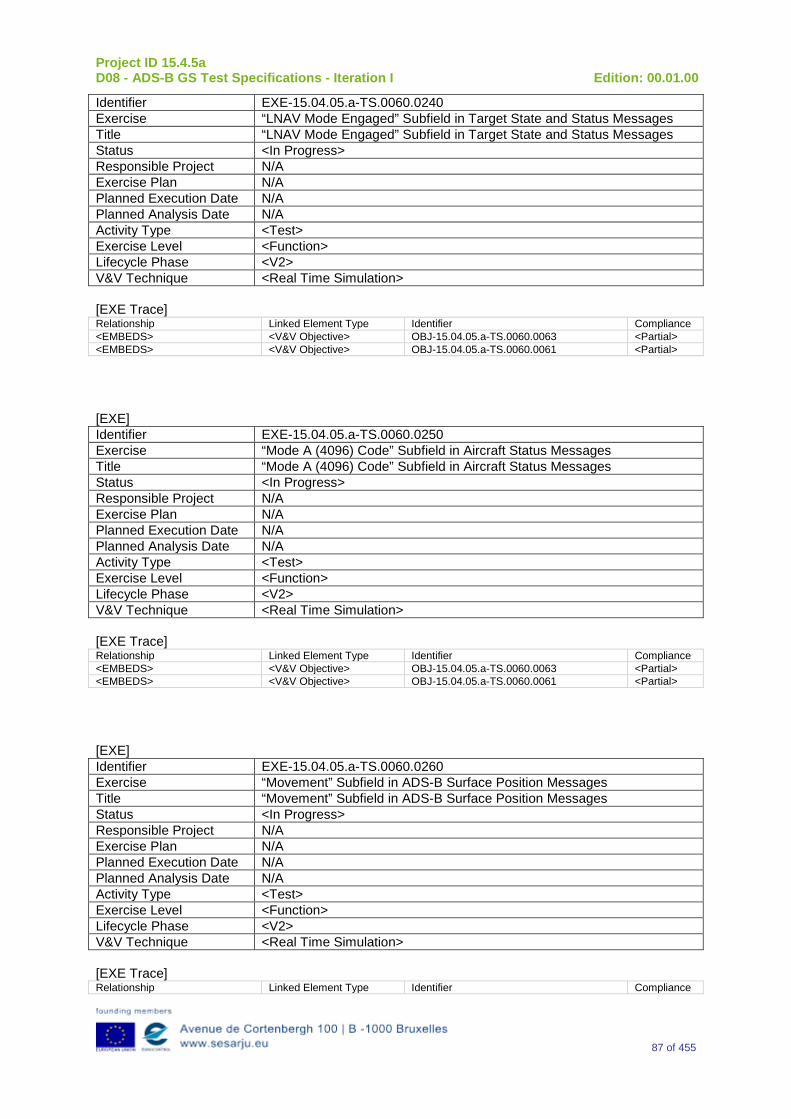
Project ID 15.4.5a D08 - ADS-B GS Test Specifications - Iteration I Edition: 00.01.00
87 of 455
Identifier EXE-15.04.05.a-TS.0060.0240 Exercise “LNAV Mode Engaged” Subfield in Target State and Status Messages Title “LNAV Mode Engaged” Subfield in Target State and Status Messages Status <In Progress> Responsible Project N/A Exercise Plan N/A Planned Execution Date N/A Planned Analysis Date N/A Activity Type <Test> Exercise Level <Function> Lifecycle Phase <V2> V&V Technique <Real Time Simulation> [EXE Trace] Relationship Linked Element Type Identifier Compliance <EMBEDS> <V&V Objective> OBJ-15.04.05.a-TS.0060.0063 <Partial> <EMBEDS> <V&V Objective> OBJ-15.04.05.a-TS.0060.0061 <Partial>
[EXE] Identifier EXE-15.04.05.a-TS.0060.0250 Exercise “Mode A (4096) Code” Subfield in Aircraft Status Messages Title “Mode A (4096) Code” Subfield in Aircraft Status Messages Status <In Progress> Responsible Project N/A Exercise Plan N/A Planned Execution Date N/A Planned Analysis Date N/A Activity Type <Test> Exercise Level <Function> Lifecycle Phase <V2> V&V Technique <Real Time Simulation> [EXE Trace] Relationship Linked Element Type Identifier Compliance <EMBEDS> <V&V Objective> OBJ-15.04.05.a-TS.0060.0063 <Partial> <EMBEDS> <V&V Objective> OBJ-15.04.05.a-TS.0060.0061 <Partial>
[EXE] Identifier EXE-15.04.05.a-TS.0060.0260 Exercise “Movement” Subfield in ADS-B Surface Position Messages Title “Movement” Subfield in ADS-B Surface Position Messages Status <In Progress> Responsible Project N/A Exercise Plan N/A Planned Execution Date N/A Planned Analysis Date N/A Activity Type <Test> Exercise Level <Function> Lifecycle Phase <V2> V&V Technique <Real Time Simulation> [EXE Trace] Relationship Linked Element Type Identifier Compliance
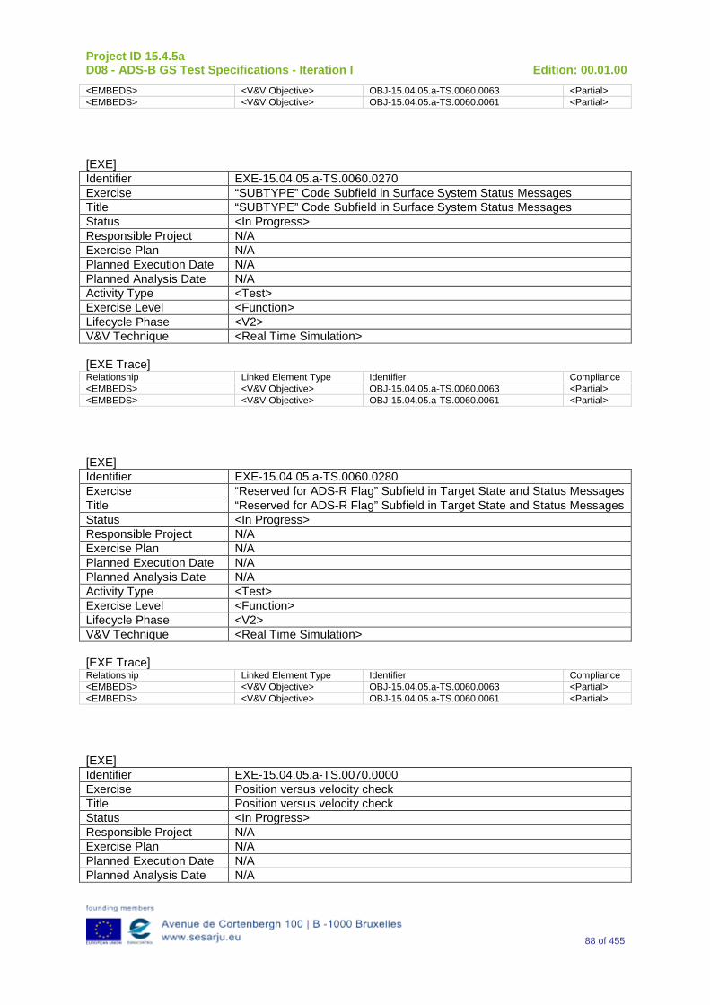
Project ID 15.4.5a D08 - ADS-B GS Test Specifications - Iteration I Edition: 00.01.00
88 of 455
<EMBEDS> <V&V Objective> OBJ-15.04.05.a-TS.0060.0063 <Partial> <EMBEDS> <V&V Objective> OBJ-15.04.05.a-TS.0060.0061 <Partial>
[EXE] Identifier EXE-15.04.05.a-TS.0060.0270 Exercise “SUBTYPE” Code Subfield in Surface System Status Messages Title “SUBTYPE” Code Subfield in Surface System Status Messages Status <In Progress> Responsible Project N/A Exercise Plan N/A Planned Execution Date N/A Planned Analysis Date N/A Activity Type <Test> Exercise Level <Function> Lifecycle Phase <V2> V&V Technique <Real Time Simulation> [EXE Trace] Relationship Linked Element Type Identifier Compliance <EMBEDS> <V&V Objective> OBJ-15.04.05.a-TS.0060.0063 <Partial> <EMBEDS> <V&V Objective> OBJ-15.04.05.a-TS.0060.0061 <Partial>
[EXE] Identifier EXE-15.04.05.a-TS.0060.0280 Exercise “Reserved for ADS-R Flag” Subfield in Target State and Status Messages Title “Reserved for ADS-R Flag” Subfield in Target State and Status Messages Status <In Progress> Responsible Project N/A Exercise Plan N/A Planned Execution Date N/A Planned Analysis Date N/A Activity Type <Test> Exercise Level <Function> Lifecycle Phase <V2> V&V Technique <Real Time Simulation> [EXE Trace] Relationship Linked Element Type Identifier Compliance <EMBEDS> <V&V Objective> OBJ-15.04.05.a-TS.0060.0063 <Partial> <EMBEDS> <V&V Objective> OBJ-15.04.05.a-TS.0060.0061 <Partial>
[EXE] Identifier EXE-15.04.05.a-TS.0070.0000 Exercise Position versus velocity check Title Position versus velocity check Status <In Progress> Responsible Project N/A Exercise Plan N/A Planned Execution Date N/A Planned Analysis Date N/A
Project ID 15.4.5a D08 - ADS-B GS Test Specifications - Iteration I Edition: 00.01.00
89 of 455
Activity Type <Test> Exercise Level <Function> Lifecycle Phase <V2> V&V Technique <Real Time Simulation> [EXE Trace] Relationship Linked Element Type Identifier Compliance <EMBEDS> <V&V Objective> OBJ-15.04.05.a-TS.0070.0064 <Full>
4.2 Verification Exercises Planning N/A.
Project ID 15.4.5a D08 - ADS-B GS Test Specifications - Iteration I Edition: 00.01.00
90 of 455
5 References [1] SJU 15.04.05a Specification Baseline Document, D17, Ed. 00.01.00, Oct 2010 [2] SJU 15.04.05a, ADS-B Surveillance System Specifications D18 [3] SJU 15.04.05a, ADS-B Ground Station Specifications, D05 [4] SJU 15.04.05a, Interface Specifications, D07 [5] SESAR Requirements and V&V Guidelines Latest version [6] SESAR Toolbox User Manual Latest version [7] EUROCAE/RTCA MOPS for 1090 MHz ADS-B, ED-102/DO-260, Sept. 2000 [8] RTCA MOPS for 1090ES ADS-B and TIS-B, DO-260A, Dec. 2006 (includes Changes 1 and
2) [9] EUROCAE/RTCA MOPS for 1090ES ADS-B and TIS-B, ED-102A/DO-260B, Dec. 2009 [10] EUROCAE/RTCA SPIR Document for ADS-B NRA Application, ED-126/DO-303, Dec. 2006 [11] EUROCAE/RTCA SPIR Document for ADS-B RAD Application, ED-161/DO-318, Sept. 2009 [12] EUROCAE ED129: Technical Specification for a 1090 MHz Extended Squitter ADS-B Ground
Station, June 2010 [13] EUROCONTROL ASTERIX Standards CAT 21, Ed 1.8, Jan 2011, [14] EUROCONTROL ASTERIX Standards CAT 23, Ed 1.2, March 2009 [15] EUROCONTROL ASTERIX Standards CAT 62, ED 1.10, December 2009 [16] EUROCONTROL ASTERIX Standards CAT 63, Ed 1.3, July 2007 [17] EUROCONTROL ARTAS V8, System/Segment Specifications, Doc. 46 127 300 – 305
Project ID 15.4.5a D08 - ADS-B GS Test Specifications - Iteration I Edition: 00.01.00
91 of 455
Appendix A Verification Exercise EXE-15.04.05.a-TS.0010.0000 GS receiving function
A.1Exercise Scope and Justification
A.1.1 Exercise Level The level of the exercise is functional.
A.1.2Exercise Type The type of this exercise is Test.
A.1.3 Description of the system being addressed; Ground Station ADS–B.
A.1.4 Context of the verification exercise This document is applied to FAT (Factory Acceptance Test).
A.1.5 Required Datasets 1090MHz Extended Squitter Messages input and 1090GS ASTERIX output.
A.1.6 Verification objectives
OBJ-15.04.05.a-TS.0010.0001 The aim of this objective is to check that the “Ground ADS-B Receive” function receives ADS-B messages, decode, package and time-stamp the data, and send ADS-B Surveillance Reports to the ATC Processing System, i.e., the “Ground ADS-B Processing” function.
A.1.7Inputs 1090 MHz Extended Squitter messages in accordance to the format defined in DO260, DO260A and DO260B.
-Messages with DF = 17 form an airborne target
-Messages with DF = 18 and CF = 0 or 1 from an airborne target
-Messages with DF = 19 and AF = 0
A.1.8 Outputs ASTERIX reports relevant to 1090 MHz Extended Squitter messages generated at input.
A.1.9 Entrance criteria Starting the generation of 1090 MHz Extended Squitter messages set as indicated in the table below.
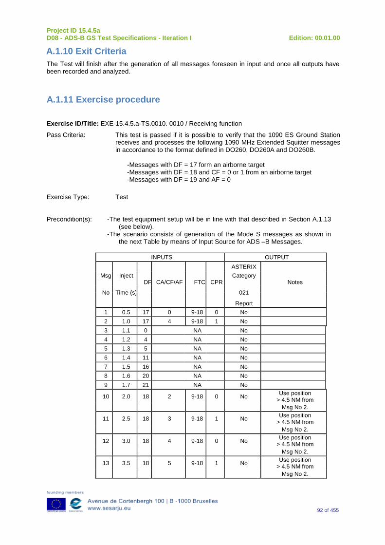
Project ID 15.4.5a D08 - ADS-B GS Test Specifications - Iteration I Edition: 00.01.00
92 of 455
A.1.10 Exit Criteria The Test will finish after the generation of all messages foreseen in input and once all outputs have been recorded and analyzed.
A.1.11 Exercise procedure
Exercise ID/Title: EXE-15.4.5.a-TS.0010. 0010 / Receiving function
Pass Criteria: This test is passed if it is possible to verify that the 1090 ES Ground Station receives and processes the following 1090 MHz Extended Squitter messages in accordance to the format defined in DO260, DO260A and DO260B.
-Messages with DF = 17 form an airborne target -Messages with DF = 18 and CF = 0 or 1 from an airborne target -Messages with DF = 19 and AF = 0
Exercise Type: Test Precondition(s): -The test equipment setup will be in line with that described in Section A.1.13
(see below). -The scenario consists of generation of the Mode S messages as shown in
the next Table by means of Input Source for ADS –B Messages.
INPUTS OUTPUT ASTERIX
Msg Inject DF CA/CF/AF
FTC CPR
Category Notes
No Time (s) 021
Report 1 0.5 17 0 9-18 0 No 2 1.0 17 4 9-18 1 No 3 1.1 0 NA No 4 1.2 4 NA No 5 1.3 5 NA No 6 1.4 11 NA No 7 1.5 16 NA No 8 1.6 20 NA No 9 1.7 21 NA No
10 2.0 18 2 9-18 0 No Use position > 4.5 NM from
Msg No 2.
11 2.5 18 3 9-18 1 No Use position > 4.5 NM from
Msg No 2.
12 3.0 18 4 9-18 0 No Use position > 4.5 NM from
Msg No 2.
13 3.5 18 5 9-18 1 No Use position > 4.5 NM from
Msg No 2.
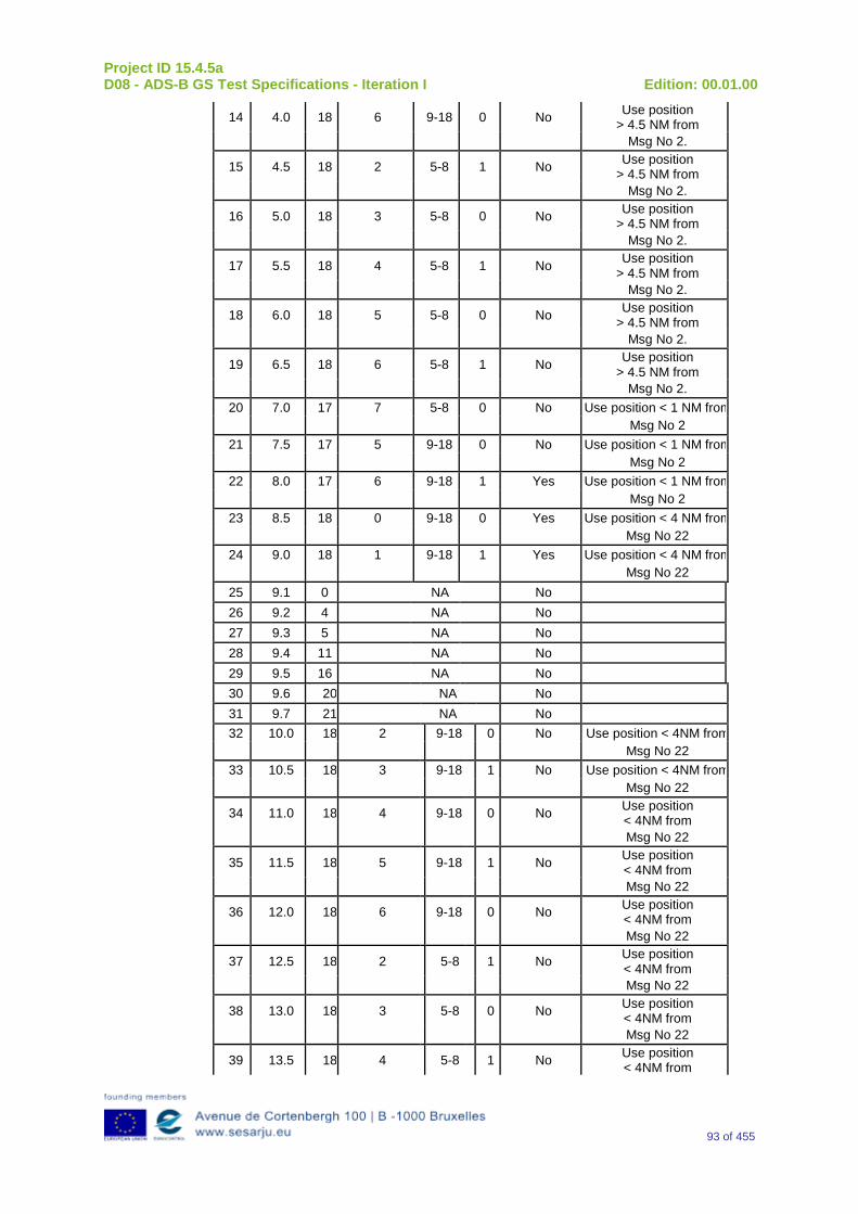
Project ID 15.4.5a D08 - ADS-B GS Test Specifications - Iteration I Edition: 00.01.00
93 of 455
14 4.0 18 6 9-18 0 No Use position > 4.5 NM from
Msg No 2.
15 4.5 18 2 5-8 1 No Use position > 4.5 NM from
Msg No 2.
16 5.0 18 3 5-8 0 No Use position > 4.5 NM from
Msg No 2.
17 5.5 18 4 5-8 1 No Use position > 4.5 NM from
Msg No 2.
18 6.0 18 5 5-8 0 No Use position > 4.5 NM from
Msg No 2.
19 6.5 18 6 5-8 1 No Use position > 4.5 NM from
Msg No 2. 20 7.0 17 7 5-8 0 No Use position < 1 NM from
Msg No 2 21 7.5 17 5 9-18 0 No Use position < 1 NM from
Msg No 2 22 8.0 17 6 9-18 1 Yes Use position < 1 NM from
Msg No 2 23 8.5 18 0 9-18 0 Yes Use position < 4 NM from
Msg No 22 24 9.0 18 1 9-18 1 Yes Use position < 4 NM from
Msg No 22 25 9.1 0 NA No 26 9.2 4 NA No 27 9.3 5 NA No 28 9.4 11 NA No 29 9.5 16 NA No 30 9.6 20 NA No 31 9.7 21 NA No 32 10.0 18 2 9-18 0 No Use position < 4NM from
Msg No 22 33 10.5 18 3 9-18 1 No Use position < 4NM from
Msg No 22
34 11.0 18 4 9-18 0 No Use position < 4NM from
Msg No 22
35 11.5 18 5 9-18 1 No Use position < 4NM from
Msg No 22
36 12.0 18 6 9-18 0 No Use position < 4NM from
Msg No 22
37 12.5 18 2 5-8 1 No Use position < 4NM from
Msg No 22
38 13.0 18 3 5-8 0 No Use position < 4NM from
Msg No 22
39 13.5 18 4 5-8 1 No Use position < 4NM from
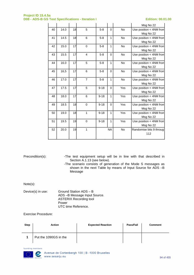
Project ID 15.4.5a D08 - ADS-B GS Test Specifications - Iteration I Edition: 00.01.00
94 of 455
Msg No 22 40 14.0 18 5 5-8 0 No Use position < 4NM from
Msg No 22 41 14.5 18 6 5-8 1 No Use position < 4NM from
Msg No 22 42 15.0 17 0 5-8 1 No Use position < 4NM from
Msg No 22 43 15.5 17 4 5-8 0 No Use position < 4NM from
Msg No 22 44 16.0 17 5 5-8 1 No Use position < 4NM from
Msg No 22 45 16,5 17 6 5-8 0 No Use position < 4NM from
Msg No 22 46 17.0 17 7 5-8 1 No Use position < 4NM from
Msg No 22 47 17.5 17 5 9-18 0 Yes Use position < 4NM from
Msg No 22 48 18.0 17 6 9-18 1 Yes Use position < 4NM from
Msg No 22 49 18.5 18 0 9-18 0 Yes Use position < 4NM from
Msg No 22 50 19.0 18 1 9-18 1 Yes Use position < 4NM from
Msg No 22 51 19.5 19 0 9-18 1 Yes Use position < 4NM from
Msg No 22 52 20.0 19 1 NA No Randomise bits 9 through
112
Precondition(s): -The test equipment setup will be in line with that described in
Section A.1.13 (see below). -The scenario consists of generation of the Mode S messages as
shown in the next Table by means of Input Source for ADS –B Message
Note(s): Device(s) in use: Ground Station ADS – B
ADS –B Message Input Source. ASTERIX Recording tool Power UTC time Reference.
Exercise Procedure: Step Action Expected Reaction Pass/Fail Comment
1 Put the 1090GS in the
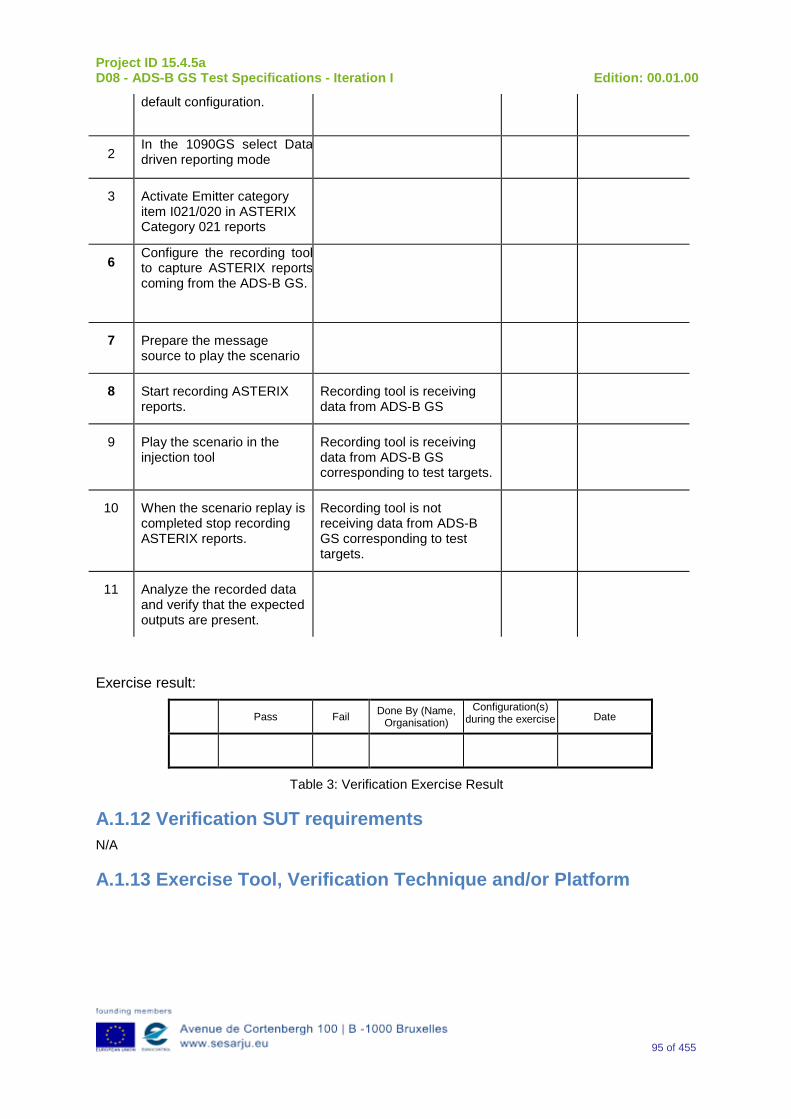
Project ID 15.4.5a D08 - ADS-B GS Test Specifications - Iteration I Edition: 00.01.00
95 of 455
default configuration.
2 In the 1090GS select Data driven reporting mode
3 Activate Emitter category item I021/020 in ASTERIX Category 021 reports
6 Configure the recording tool to capture ASTERIX reports coming from the ADS-B GS.
7 Prepare the message source to play the scenario
8 Start recording ASTERIX reports.
Recording tool is receiving data from ADS-B GS
9 Play the scenario in the injection tool
Recording tool is receiving data from ADS-B GS corresponding to test targets.
10 When the scenario replay is completed stop recording ASTERIX reports.
Recording tool is not receiving data from ADS-B GS corresponding to test targets.
11 Analyze the recorded data and verify that the expected outputs are present.
Exercise result:
Pass Fail Done By (Name, Organisation)
Configuration(s) during the exercise Date
Table 3: Verification Exercise Result
A.1.12 Verification SUT requirements N/A
A.1.13 Exercise Tool, Verification Technique and/or Platform
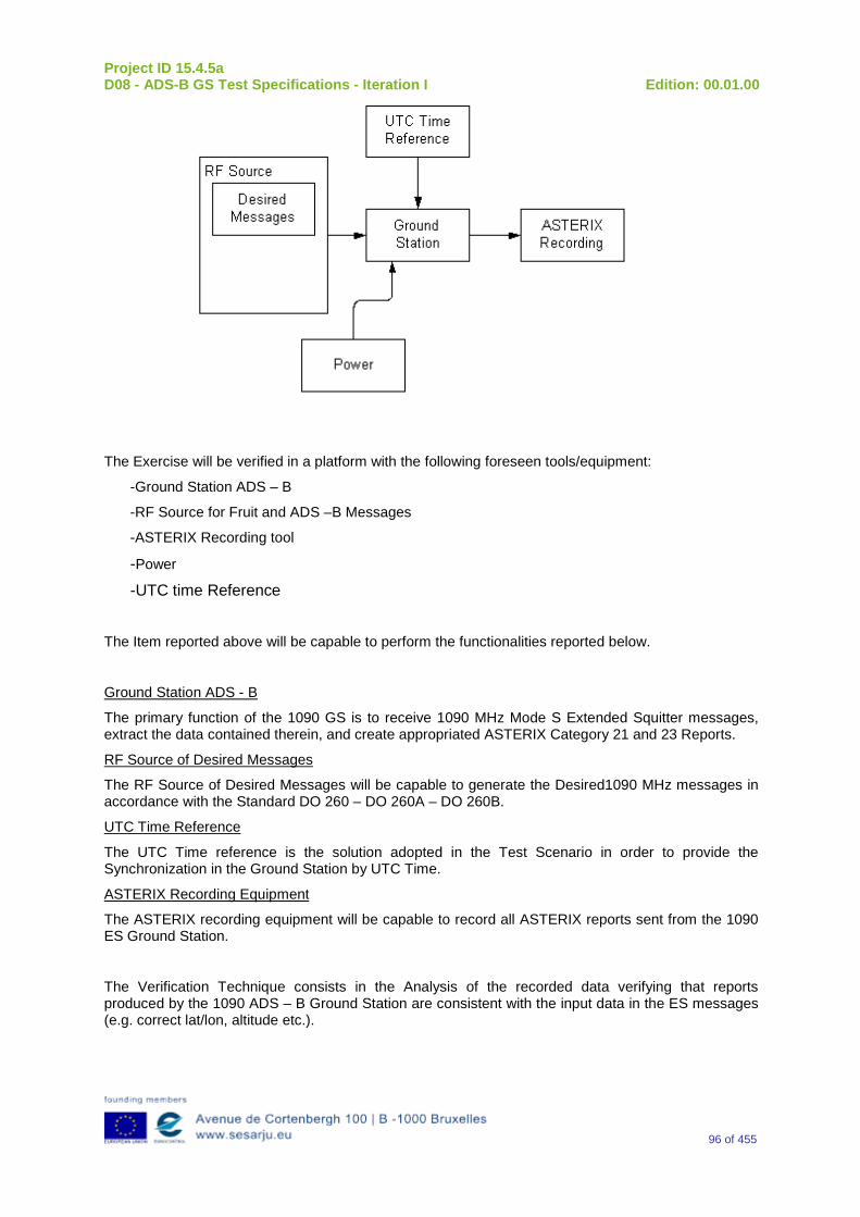
Project ID 15.4.5a D08 - ADS-B GS Test Specifications - Iteration I Edition: 00.01.00
96 of 455
The Exercise will be verified in a platform with the following foreseen tools/equipment:
-Ground Station ADS – B
-RF Source for Fruit and ADS –B Messages
-ASTERIX Recording tool
-Power -UTC time Reference
The Item reported above will be capable to perform the functionalities reported below.
Ground Station ADS - B
The primary function of the 1090 GS is to receive 1090 MHz Mode S Extended Squitter messages, extract the data contained therein, and create appropriated ASTERIX Category 21 and 23 Reports.
RF Source of Desired Messages
The RF Source of Desired Messages will be capable to generate the Desired1090 MHz messages in accordance with the Standard DO 260 – DO 260A – DO 260B.
UTC Time Reference
The UTC Time reference is the solution adopted in the Test Scenario in order to provide the Synchronization in the Ground Station by UTC Time.
ASTERIX Recording Equipment
The ASTERIX recording equipment will be capable to record all ASTERIX reports sent from the 1090 ES Ground Station.
The Verification Technique consists in the Analysis of the recorded data verifying that reports produced by the 1090 ADS – B Ground Station are consistent with the input data in the ES messages (e.g. correct lat/lon, altitude etc.).
Project ID 15.4.5a D08 - ADS-B GS Test Specifications - Iteration I Edition: 00.01.00
97 of 455
A.1.14 Verification Platform needs See section 3.5 Verification Platform Needs.
A.1.15 Platform Configuration N/A
A.1.16 Configuration(s) Identification of the Verification Platform N/A
A.1.17 Links to other Verification Exercises N/A
A.1.18 Representatively level/ limitations N/A
A.2 Exercises Planning and management
A.2.1 Activities
A.2.1.1Preparatory activities Set up the tools/equipment listed in 3.5 and A.1.13 in order to meet the Test Preconditions.
A.2.1.2 Execution activities Play the scenario generating in the input the desired1090 MHz messages and record the relevant ASTERIX output.
A.2.1.3 Post execution activities Verify that the information reported in the Recorded ASTERIX Reports is consistent with the input messages and expected output.
A.2.2 Human Resources. N/A
A.2.3 Responsibilities in the exercise N/A
A.2.4 Training N/A
A.2.5 Time planning N/A
A.2.6 Risks. N/A
Project ID 15.4.5a D08 - ADS-B GS Test Specifications - Iteration I Edition: 00.01.00
98 of 455
A.2.7 Errors and Observation handling N/A
A.3 Analysis Specification
A.3.1 Data collection methods The data collection during the test will be Qualitative. In fact after test execution the analysis of ASTERIX Data will be performed verifying that the values reported in output are in line with the values generated in input.
A.3.2 Analysis method N/A
A.3.3 Data logging requirements The data logging requirements for this scenario will foresee at least ASTERIX CAT 21 and ASTERIX CAT 23 item.
Project ID 15.4.5a D08 - ADS-B GS Test Specifications - Iteration I Edition: 00.01.00
99 of 455
Appendix B Verification Exercise EXE-15.04.05.a-TS.0010.0010 GS decoding function
B.1Exercise Scope and Justification
B.1.1 Exercise Level The level of the exercise is functional.
B.1.2 Exercise Type The type of this exercise is Test.
B.1.3 Description of the system being addressed; Ground Station ADS – B.
B.1.4 Context of the verification exercise This document is applied to FAT (Factory Acceptance Test).
B.1.5 Required Datasets 1090MHz Extended Squitter Messages input and 1090GS ASTERIX output.
B.1.6 Verification objectives The aim of this test procedure is to check that the system detects the version of the 1090 ES MOPS of messages received, decodes the messages according to the detected version, and reports the parameters contained therein accordingly. During the test, all the transitions between version states 0, 1 and unrecognized are tested. In future iterations, the test will be upgraded to include version 2 and decode the information correctly.
OBJ-15.04.05.a-TS.0010.0001 The aim of this objective is to check that the “Ground ADS-B Receive” function receives ADS-B messages, decode, package and time-stamp the data, and send ADS-B Surveillance Reports to the ATC Processing System, i.e., the “Ground ADS-B Processing” function.
B.1.7Inputs 1090 MHz Extended Squitter messages in accordance to the format defined in DO260, DO260A and DO206B. Position of the targets shall be inside the maximum range configured in the GS.
B.1.8 Outputs ASTERIX reports relevant to 1090 MHz Extended Squitter messages generated in input.
B.1.9 Entrance criteria Starting the generation of 1090 MHz Extended Squitter messages set as indicated in the table below.
Project ID 15.4.5a D08 - ADS-B GS Test Specifications - Iteration I Edition: 00.01.00
100 of 455
B.1.10 Exit Criteria The Test will finish after the generation of all the messages foreseen in the input and once all outputs have been recorded and analyzed.
B.1.11 Exercise procedure
Exercise ID/Title: EXE-15.4.5.a-TS.0010. 0010 / decoding function
Pass Criteria: This test is passed if it is possible to verify that the 1090 ES Ground Station decodes the following 1090 MHz Extended Squitter messages in accordance to the format defined in DO260, DO260A and DO260B.
-
Exercise Type: Test Precondition(s): The following scenario has been designed to cover all possible version state
transitions:
Step 1: Target acquisition and version 0 assumed. VNS=0, VN=0.
Step 2: Change from version 0 assumed to version 0 confirmed.
Step 3: Change from version 0 confirmed to version 1.
Step 4: Change from version 1 confirmed to version 0 confirmed.
Step 5: Change from version 0 confirmed to unrecognized version. Note: VNS is 1 for unrecognized version.
Step 6: Change from unrecognized version to version 0 confirmed.
Step 7: 92 Seconds of position messages only. Version information should expire, resulting in assumed version 0. VNS=0, VN=0.
Step 8: Change from version 0 assumed to version 1.
Step 9: Change from version 1 confirmed to unrecognized version. Note: VNS is 1 for unrecognized version.
Step 10: Change from unrecognized version to version 1 confirmed.
Step 11: 92 Seconds of position messages only. Version information should expire, resulting in assumed version 0. VNS=0, VN=0.
Step 12: Change from version 0 assumed to unrecognized version. Note: VNS is 1 for unrecognized version.
Step 13: 92 Seconds of position messages only. Version information should expire, resulting in assumed version 0. VNS=0, VN=0.
Once these steps are completed, all possible version state transitions are covered.
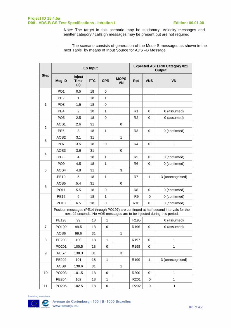
Project ID 15.4.5a D08 - ADS-B GS Test Specifications - Iteration I Edition: 00.01.00
101 of 455
Note: The target in this scenario may be stationary. Velocity messages and emitter category / callsign messages may be present but are not required
- The scenario consists of generation of the Mode S messages as shown in the
next Table by means of Input Source for ADS –B Message
Step
ES Input Expected ASTERIX Category 021 Output
Msg ID Inject Time
(s) FTC CPR MOPS
VN Rpt VNS VN
1
PO1 0.5 18 0
PE2 1 18 1
PO3 1.5 18 0
PE4 2 18 1 R1 0 0 (assumed)
PO5 2.5 18 0 R2 0 0 (assumed)
2 AOS1 2.6 31 0
PE6 3 18 1 R3 0 0 (confirmed)
3 AOS2 3.1 31 1
PO7 3.5 18 0 R4 0 1
4 AOS3 3.6 31 0
PE8 4 18 1 R5 0 0 (confirmed)
5
PO9 4.5 18 1 R6 0 0 (confirmed)
AOS4 4.8 31 3
PE10 5 18 1 R7 1 3 (unrecognised)
6 AOS5 5.4 31 0
PO11 5.5 18 0 R8 0 0 (confirmed)
7
PE12 6 18 1 R9 0 0 (confirmed)
PO13 6.5 18 0 R10 0 0 (confirmed)
Position messages (PE14 through PO197) are continued at half-second intervals for the next 92 seconds. No AOS messages are to be injected during this period.
PE198 99 18 1 R195 0 (assumed)
PO199 99.5 18 0 R196 0 0 (assumed)
8
AOS6 99.6 31 1
PE200 100 18 1 R197 0 1
9
PO201 100.5 18 0 R198 0 1
AOS7 138.3 31 3
PE202 101 18 1 R199 1 3 (unrecognised)
10
AOS8 138.6 31 1
PO203 101.5 18 0 R200 0 1
11
PE204 102 18 1 R201 0 1
PO205 102.5 18 0 R202 0 1
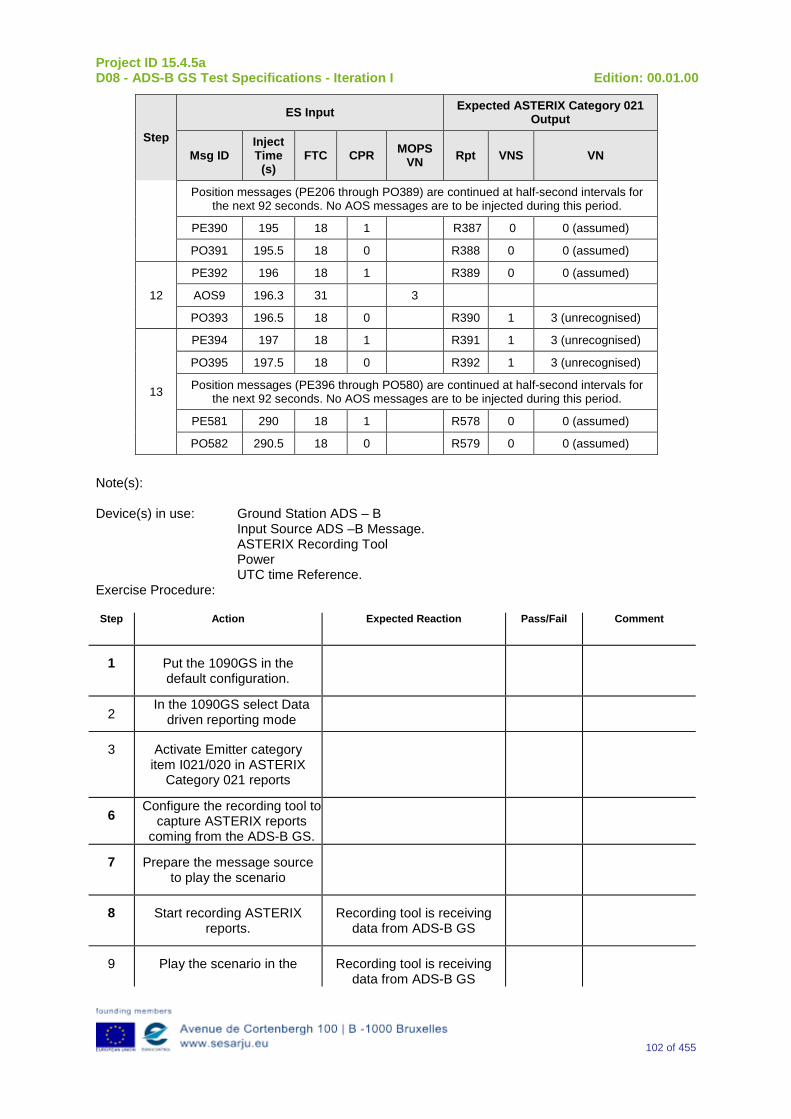
Project ID 15.4.5a D08 - ADS-B GS Test Specifications - Iteration I Edition: 00.01.00
102 of 455
Step
ES Input Expected ASTERIX Category 021 Output
Msg ID Inject Time
(s) FTC CPR MOPS
VN Rpt VNS VN
Position messages (PE206 through PO389) are continued at half-second intervals for the next 92 seconds. No AOS messages are to be injected during this period.
PE390 195 18 1 R387 0 0 (assumed)
PO391 195.5 18 0 R388 0 0 (assumed)
12
PE392 196 18 1 R389 0 0 (assumed)
AOS9 196.3 31 3
PO393 196.5 18 0 R390 1 3 (unrecognised)
13
PE394 197 18 1 R391 1 3 (unrecognised)
PO395 197.5 18 0 R392 1 3 (unrecognised)
Position messages (PE396 through PO580) are continued at half-second intervals for the next 92 seconds. No AOS messages are to be injected during this period.
PE581 290 18 1 R578 0 0 (assumed)
PO582 290.5 18 0 R579 0 0 (assumed)
Note(s): Device(s) in use: Ground Station ADS – B
Input Source ADS –B Message. ASTERIX Recording Tool Power UTC time Reference.
Exercise Procedure: Step Action Expected Reaction Pass/Fail Comment
1 Put the 1090GS in the default configuration.
2 In the 1090GS select Data
driven reporting mode
3 Activate Emitter category item I021/020 in ASTERIX
Category 021 reports
6 Configure the recording tool to
capture ASTERIX reports coming from the ADS-B GS.
7 Prepare the message source to play the scenario
8 Start recording ASTERIX reports.
Recording tool is receiving data from ADS-B GS
9 Play the scenario in the Recording tool is receiving data from ADS-B GS
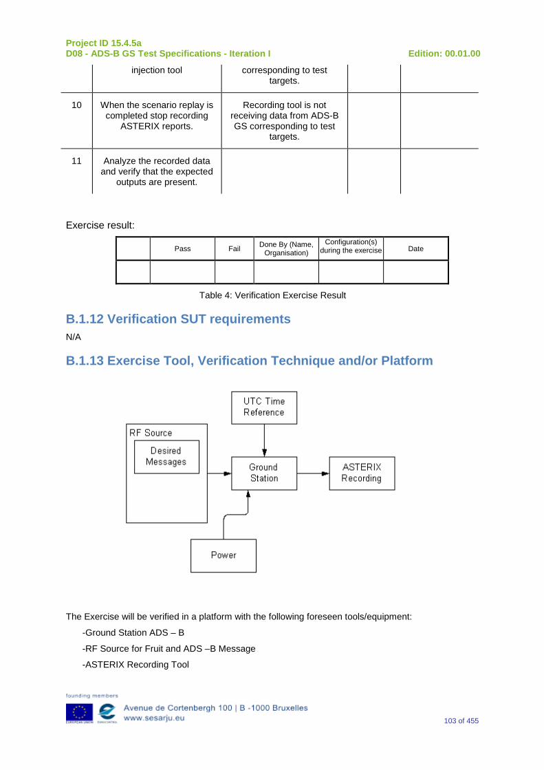
Project ID 15.4.5a D08 - ADS-B GS Test Specifications - Iteration I Edition: 00.01.00
103 of 455
injection tool corresponding to test targets.
10 When the scenario replay is completed stop recording
ASTERIX reports.
Recording tool is not receiving data from ADS-B GS corresponding to test
targets.
11 Analyze the recorded data and verify that the expected
outputs are present.
Exercise result:
Pass Fail Done By (Name, Organisation)
Configuration(s) during the exercise Date
Table 4: Verification Exercise Result
B.1.12 Verification SUT requirements N/A
B.1.13 Exercise Tool, Verification Technique and/or Platform
The Exercise will be verified in a platform with the following foreseen tools/equipment:
-Ground Station ADS – B
-RF Source for Fruit and ADS –B Message
-ASTERIX Recording Tool
Project ID 15.4.5a D08 - ADS-B GS Test Specifications - Iteration I Edition: 00.01.00
104 of 455
-Power
-UTC time Reference
The Item reported above will be capable to perform the functionalities reported below.
Ground Station ADS-B
The primary function of the 1090 GS is to receive 1090 MHz Mode S Extended Squitter messages, extract the data contained therein and create appropriated ASTERIX Category 21 and 23 Reports.
RF Source of Desired Messages
The RF Source of Desired Messages will be capable to generate the Desired1090 MHz messages in accordance with the Standard DO 260 – DO 260A – DO 260B.
UTC Time Reference
The UTC Time reference is the solution adopted in the Test Scenario in order to provide the Synchronization in the Ground Station by UTC Time.
ASTERIX Recording Equipment
The ASTERIX recording equipment will be capable to record all ASTERIX reports sent from the 1090 ES Ground Station.
The Verification Technique consists in the Analysis of the recorded data verifying that reports produced by the 1090 ADS – B Ground Station are consistent with the input data in the ES messages (e.g. correct lat/lon, altitude etc.).
B.1.14Verification Platform needs See section 3.5 Verification Platform Needs.
B.1.15 Platform Configuration N/A
B.1.16 Configuration(s) Identification of the Verification Platform N/A
B.1.17 Links to other Verification Exercises N/A
B.1.18 Representatively level/ limitations N/A
B.2 Exercises Planning and management
B.2.1 Activities
B.2.1.1Preparatory activities Set up the tools/equipment listed in 3.5 and B.1.13 in order to meet the Test Preconditions.
Project ID 15.4.5a D08 - ADS-B GS Test Specifications - Iteration I Edition: 00.01.00
105 of 455
B.2.1.2 Execution activities Play the scenario generating in the input the desired1090 MHz messages and record the relevant ASTERIX output.
B.2.1.3 Post execution activities Verify that the information reported in the Recorded ASTERIX Reports is consistent with the input messages and expected output.
B.2.2 Human Resources. N/A
B.2.3 Responsibilities in the exercise N/A
B.2.4 Training N/A
B.2.5 Time planning N/A
B.2.6 Risks. N/A
B.2.7 Errors and Observation handling N/A
B.3 Analysis Specification
B.3.1 Data collection methods The data’s collection during the test will be Qualitative. In fact after test execution the analysis of ASTERIX Data will be performed verifying that the values reported in output are in line with the values generated in input.
B.3.2Analysis method N/A
B.3.3 Data logging requirements The data logging requirements for this scenario will foresee at least ASTERIX CAT 21 and ASTERIX CAT 23 item.
Project ID 15.4.5a D08 - ADS-B GS Test Specifications - Iteration I Edition: 00.01.00
106 of 455
Appendix CVerification Exercise EXE-15.04.05.a-TS.0010.0020 GS Association function 1
C.1Exercise Scope and Justification
C.1.1 Exercise Level The level of the exercise is functional.
C.1.2 Exercise Type The type of this exercise is Test.
C.1.3 Description of the system being addressed; ADS-B Ground Station.
C.1.4 Context of the verification exercise This document is applied to FAT (Factory Acceptance Test).
C.1.5 Required Datasets 1090MHz Extended Squitter Messages input and 1090GS ASTERIX output.
C.1.6 Verification objectives Verify the following that the 1090 ES Ground Station meets the minimum requirements for Target Data Maintenance. This includes verifying that:
•Local decoding is used
•Positions that fail the Local Decoding Reasonableness Test are not used as a reference position for subsequent local decodes
•The Local Decoding Reasonableness Test works
OBJ-15.04.05.a-TS.0010.0001 The aim of this objective is to check that the “Ground ADS-B Receive” function receives ADS-B messages, decode, package and time-stamp the data, and send ADS-B Surveillance Reports to the ATC Processing System, i.e., the “Ground ADS-B Processing” function.
C.1.7Inputs 1090 MHz Extended Squitter messages in accordance to the format defined in DO260, DO260A: and DO206B
C.1.8 Outputs ASTERIX reports relevant to 1090 MHz Extended Squitter messages generated in input.
C.1.9 Entrance criteria Starting the generation of 1090 MHz Extended Squitter messages set as indicated in the table below.
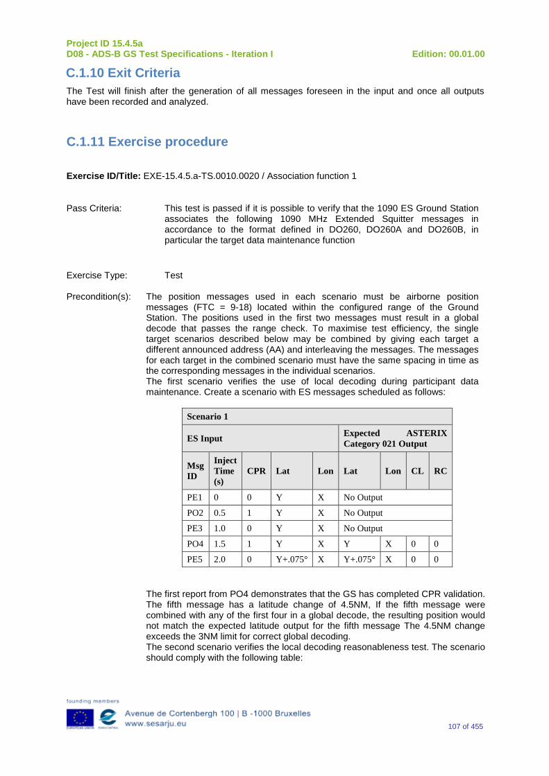
Project ID 15.4.5a D08 - ADS-B GS Test Specifications - Iteration I Edition: 00.01.00
107 of 455
C.1.10 Exit Criteria The Test will finish after the generation of all messages foreseen in the input and once all outputs have been recorded and analyzed.
C.1.11 Exercise procedure
Exercise ID/Title: EXE-15.4.5.a-TS.0010.0020 / Association function 1
Pass Criteria: This test is passed if it is possible to verify that the 1090 ES Ground Station associates the following 1090 MHz Extended Squitter messages in accordance to the format defined in DO260, DO260A and DO260B, in particular the target data maintenance function
Exercise Type: Test Precondition(s): The position messages used in each scenario must be airborne position
messages (FTC = 9-18) located within the configured range of the Ground Station. The positions used in the first two messages must result in a global decode that passes the range check. To maximise test efficiency, the single target scenarios described below may be combined by giving each target a different announced address (AA) and interleaving the messages. The messages for each target in the combined scenario must have the same spacing in time as the corresponding messages in the individual scenarios. The first scenario verifies the use of local decoding during participant data maintenance. Create a scenario with ES messages scheduled as follows:
Scenario 1
ES Input Expected ASTERIX Category 021 Output
Msg ID
Inject Time (s)
CPR Lat Lon Lat Lon CL RC
PE1 0 0 Y X No Output
PO2 0.5 1 Y X No Output
PE3 1.0 0 Y X No Output
PO4 1.5 1 Y X Y X 0 0
PE5 2.0 0 Y+.075° X Y+.075° X 0 0 The first report from PO4 demonstrates that the GS has completed CPR validation. The fifth message has a latitude change of 4.5NM, If the fifth message were combined with any of the first four in a global decode, the resulting position would not match the expected latitude output for the fifth message The 4.5NM change exceeds the 3NM limit for correct global decoding. The second scenario verifies the local decoding reasonableness test. The scenario should comply with the following table:
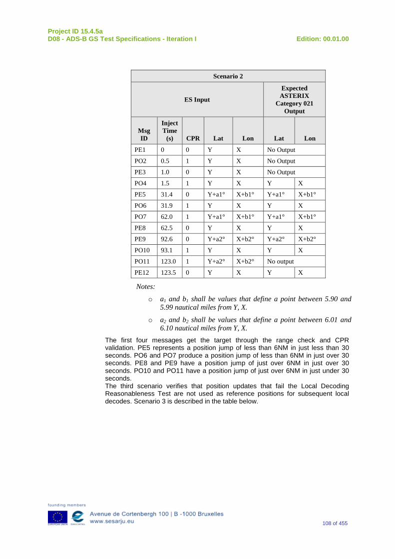
Project ID 15.4.5a D08 - ADS-B GS Test Specifications - Iteration I Edition: 00.01.00
108 of 455
Scenario 2
ES Input
Expected ASTERIX
Category 021 Output
Msg ID
Inject Time
(s) CPR Lat Lon Lat Lon
PE1 0 0 Y X No Output
PO2 0.5 1 Y X No Output
PE3 1.0 0 Y X No Output
PO4 1.5 1 Y X Y X
PE5 31.4 0 Y+a1° X+b1° Y+a1° X+b1°
PO6 31.9 1 Y X Y X
PO7 62.0 1 Y+a1° X+b1° Y+a1° X+b1°
PE8 62.5 0 Y X Y X
PE9 92.6 0 Y+a2° X+b2° Y+a2° X+b2°
PO10 93.1 1 Y X Y X
PO11 123.0 1 Y+a2° X+b2° No output
PE12 123.5 0 Y X Y X
Notes:
o a1 and b1 shall be values that define a point between 5.90 and 5.99 nautical miles from Y, X.
o a2 and b2 shall be values that define a point between 6.01 and 6.10 nautical miles from Y, X.
The first four messages get the target through the range check and CPR validation. PE5 represents a position jump of less than 6NM in just less than 30 seconds. PO6 and PO7 produce a position jump of less than 6NM in just over 30 seconds. PE8 and PE9 have a position jump of just over 6NM in just over 30 seconds. PO10 and PO11 have a position jump of just over 6NM in just under 30 seconds. The third scenario verifies that position updates that fail the Local Decoding Reasonableness Test are not used as reference positions for subsequent local decodes. Scenario 3 is described in the table below.
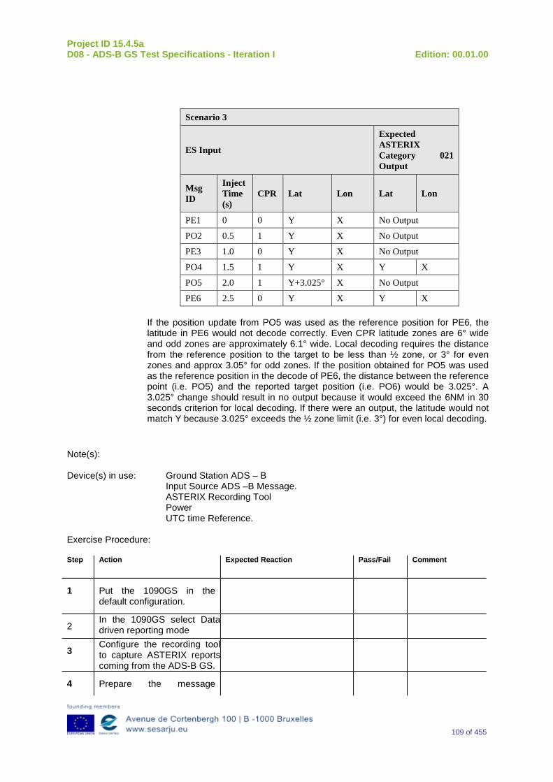
Project ID 15.4.5a D08 - ADS-B GS Test Specifications - Iteration I Edition: 00.01.00
109 of 455
Scenario 3
ES Input
Expected ASTERIX Category 021 Output
Msg ID
Inject Time (s)
CPR Lat Lon Lat Lon
PE1 0 0 Y X No Output
PO2 0.5 1 Y X No Output
PE3 1.0 0 Y X No Output
PO4 1.5 1 Y X Y X
PO5 2.0 1 Y+3.025° X No Output
PE6 2.5 0 Y X Y X If the position update from PO5 was used as the reference position for PE6, the latitude in PE6 would not decode correctly. Even CPR latitude zones are 6° wide and odd zones are approximately 6.1° wide. Local decoding requires the distance from the reference position to the target to be less than ½ zone, or 3° for even zones and approx 3.05° for odd zones. If the position obtained for PO5 was used as the reference position in the decode of PE6, the distance between the reference point (i.e. PO5) and the reported target position (i.e. PO6) would be 3.025°. A 3.025° change should result in no output because it would exceed the 6NM in 30 seconds criterion for local decoding. If there were an output, the latitude would not match Y because 3.025° exceeds the ½ zone limit (i.e. 3°) for even local decoding.
Note(s): Device(s) in use: Ground Station ADS – B
Input Source ADS –B Message. ASTERIX Recording Tool Power UTC time Reference.
Exercise Procedure: Step Action Expected Reaction Pass/Fail Comment
1 Put the 1090GS in the default configuration.
2 In the 1090GS select Data driven reporting mode
3 Configure the recording tool to capture ASTERIX reports coming from the ADS-B GS.
4 Prepare the message
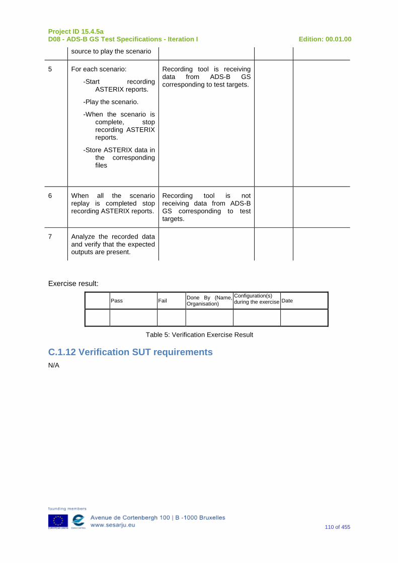
Project ID 15.4.5a D08 - ADS-B GS Test Specifications - Iteration I Edition: 00.01.00
110 of 455
source to play the scenario
5 For each scenario:
-Start recording ASTERIX reports.
-Play the scenario.
-When the scenario is complete, stop recording ASTERIX reports.
-Store ASTERIX data in the corresponding files
Recording tool is receiving data from ADS-B GS corresponding to test targets.
6 When all the scenario replay is completed stop recording ASTERIX reports.
Recording tool is not receiving data from ADS-B GS corresponding to test targets.
7 Analyze the recorded data and verify that the expected outputs are present.
Exercise result:
Pass Fail Done By (Name, Organisation)
Configuration(s) during the exercise Date
Table 5: Verification Exercise Result
C.1.12 Verification SUT requirements N/A
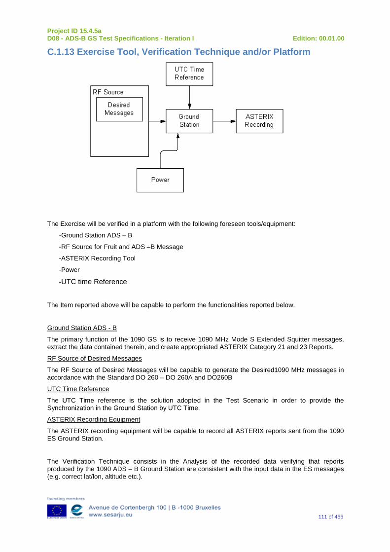
Project ID 15.4.5a D08 - ADS-B GS Test Specifications - Iteration I Edition: 00.01.00
111 of 455
C.1.13 Exercise Tool, Verification Technique and/or Platform
The Exercise will be verified in a platform with the following foreseen tools/equipment:
-Ground Station ADS – B
-RF Source for Fruit and ADS –B Message
-ASTERIX Recording Tool
-Power
-UTC time Reference
The Item reported above will be capable to perform the functionalities reported below.
Ground Station ADS - B
The primary function of the 1090 GS is to receive 1090 MHz Mode S Extended Squitter messages, extract the data contained therein, and create appropriated ASTERIX Category 21 and 23 Reports.
RF Source of Desired Messages
The RF Source of Desired Messages will be capable to generate the Desired1090 MHz messages in accordance with the Standard DO 260 – DO 260A and DO260B
UTC Time Reference
The UTC Time reference is the solution adopted in the Test Scenario in order to provide the Synchronization in the Ground Station by UTC Time.
ASTERIX Recording Equipment
The ASTERIX recording equipment will be capable to record all ASTERIX reports sent from the 1090 ES Ground Station.
The Verification Technique consists in the Analysis of the recorded data verifying that reports produced by the 1090 ADS – B Ground Station are consistent with the input data in the ES messages (e.g. correct lat/lon, altitude etc.).
Project ID 15.4.5a D08 - ADS-B GS Test Specifications - Iteration I Edition: 00.01.00
112 of 455
C.1.14 Verification Platform needs See section 3.5 Verification Platform Needs.
C.1.15 Platform Configuration N/A
C.1.16 Configuration(s) Identification of the Verification Platform N/A
C.1.17 Links to other Verification Exercises N/A
C.1.18 Representatively level/ limitations N/A
C.2 Exercises Planning and management
C.2.1 Activities
C.2.1.1Preparatory activities Set up the tools/equipment listed in 3.5 and C.1.13 in order to meet the Test Preconditions.
C.2.1.2 Execution activities Play the scenario generating in the input the desired1090 MHz messages and record the relevant ASTERIX output.
C.2.1.3 Post execution activities Verify that the information reported in the Recorded ASTERIX Report is consistent with the input messages and expected output.
C.2.2 Human Resources. N/A
C.2.3 Responsibilities in the exercise N/A
C.2.4 Training N/A
C.2.5 Time planning N/A
Project ID 15.4.5a D08 - ADS-B GS Test Specifications - Iteration I Edition: 00.01.00
113 of 455
C.2.6 Risks. N/A
C.2.7 Errors and Observation handling N/A
C.3 Analysis Specification
C.3.1 Data collection methods The data’s collection during the test will be Qualitative. In fact after test execution the analysis of ASTERIX Data will be performed verifying that the values reported in output are in line with the values generated in input.
C.3.2Analysis method N/A
C.3.3 Data logging requirements The data logging requirements for this scenario will foresee at least ASTERIX CAT 21 and ASTERIX CAT 23 item.
Project ID 15.4.5a D08 - ADS-B GS Test Specifications - Iteration I Edition: 00.01.00
114 of 455
Appendix D Verification Exercise EXE-15.04.05.a-TS.0010.0030 GS Association function 2
D.1Exercise Scope and Justification
D.1.1 Exercise Level The level of the exercise is functional.
D.1.2 Exercise Type The type of this exercise is Test.
D.1.3 Description of the system being addressed; Ground Station ADS –B.
D.1.4 Context of the verification exercise This document is applied to FAT (Factory Acceptance Test).
D.1.5 Required Datasets 1090MHz Extended Squitter Messages input and 1090GS ASTERIX output.
D.1.6 Verification objectives Verify the following:
Participants shall be reinitialised after no more than 120 seconds without a position update. Messages received after the 120-second timeout shall be treated as messages from a new participant.
OBJ-15.04.05.a-TS.0010.0001 The aim of this objective is to check that the “Ground ADS-B Receive” function receives ADS-B messages, decode, package and time-stamp the data, and send ADS-B Surveillance Reports to the ATC Processing System, i.e., the “Ground ADS-B Processing” function.
D.1.7Inputs 1090 MHz Extended Squitter messages in accordance to the format defined in DO260, DO260A and DO260B.
D.1.8 Outputs ASTERIX reports relevant to 1090 MHz Extended Squitter messages generated at input.
D.1.9 Entrance criteria Starting the generation of 1090 MHz Extended Squitter messages set as indicated in the table below.
D.1.10 Exit Criteria The Test will finish after the generation and injection of input data and recording of output data.
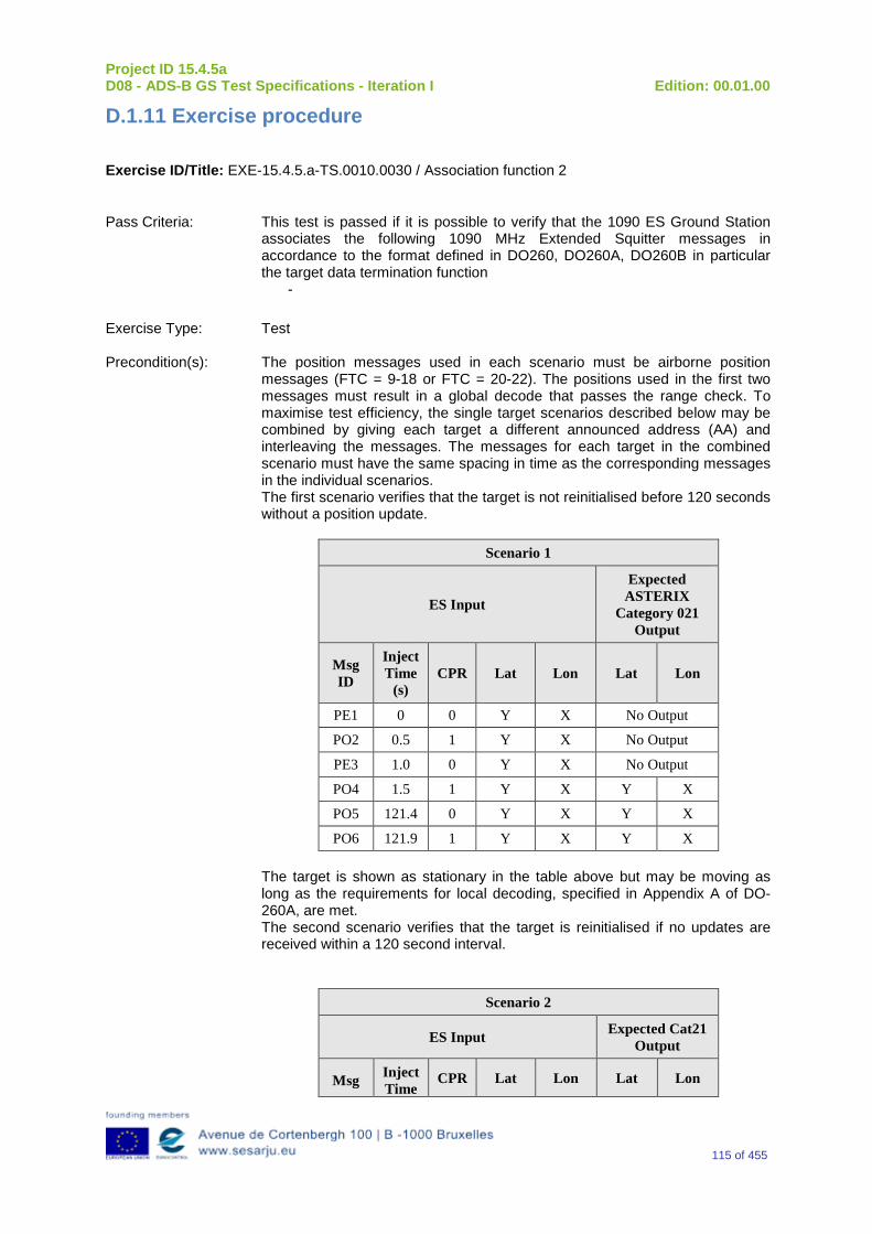
Project ID 15.4.5a D08 - ADS-B GS Test Specifications - Iteration I Edition: 00.01.00
115 of 455
D.1.11 Exercise procedure
Exercise ID/Title: EXE-15.4.5.a-TS.0010.0030 / Association function 2
Pass Criteria: This test is passed if it is possible to verify that the 1090 ES Ground Station associates the following 1090 MHz Extended Squitter messages in accordance to the format defined in DO260, DO260A, DO260B in particular the target data termination function
-
Exercise Type: Test Precondition(s): The position messages used in each scenario must be airborne position
messages (FTC = 9-18 or FTC = 20-22). The positions used in the first two messages must result in a global decode that passes the range check. To maximise test efficiency, the single target scenarios described below may be combined by giving each target a different announced address (AA) and interleaving the messages. The messages for each target in the combined scenario must have the same spacing in time as the corresponding messages in the individual scenarios. The first scenario verifies that the target is not reinitialised before 120 seconds without a position update.
Scenario 1
ES Input
Expected ASTERIX
Category 021 Output
Msg ID
Inject Time
(s) CPR Lat Lon Lat Lon
PE1 0 0 Y X No Output
PO2 0.5 1 Y X No Output
PE3 1.0 0 Y X No Output
PO4 1.5 1 Y X Y X
PO5 121.4 0 Y X Y X
PO6 121.9 1 Y X Y X The target is shown as stationary in the table above but may be moving as long as the requirements for local decoding, specified in Appendix A of DO-260A, are met. The second scenario verifies that the target is reinitialised if no updates are received within a 120 second interval.
Scenario 2
ES Input Expected Cat21 Output
Msg Inject Time
CPR Lat Lon Lat Lon
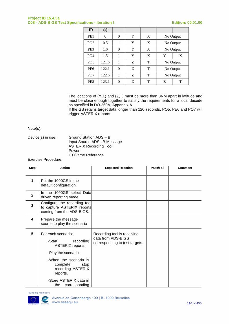
Project ID 15.4.5a D08 - ADS-B GS Test Specifications - Iteration I Edition: 00.01.00
116 of 455
ID (s)
PE1 0 0 Y X No Output
PO2 0.5 1 Y X No Output
PE3 1.0 0 Y X No Output
PO4 1.5 1 Y X Y X
PO5 121.6 1 Z T No Output
PE6 122.1 0 Z T No Output
PO7 122.6 1 Z T No Output
PE8 123.1 0 Z T Z T The locations of (Y,X) and (Z,T) must be more than 3NM apart in latitude and must be close enough together to satisfy the requirements for a local decode as specified in DO-260A, Appendix A. If the GS retains target data longer than 120 seconds, PO5, PE6 and PO7 will trigger ASTERIX reports.
Note(s): Device(s) in use: Ground Station ADS – B
Input Source ADS –B Message ASTERIX Recording Tool Power UTC time Reference
Exercise Procedure: Step Action Expected Reaction Pass/Fail Comment
1 Put the 1090GS in the default configuration.
2 In the 1090GS select Data driven reporting mode
3 Configure the recording tool to capture ASTERIX reports coming from the ADS-B GS.
4 Prepare the message source to play the scenario
5 For each scenario:
-Start recording ASTERIX reports.
-Play the scenario.
-When the scenario is complete, stop recording ASTERIX reports.
-Store ASTERIX data in the corresponding
Recording tool is receiving data from ADS-B GS corresponding to test targets.
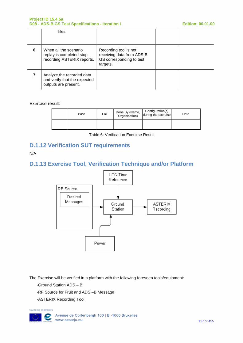
Project ID 15.4.5a D08 - ADS-B GS Test Specifications - Iteration I Edition: 00.01.00
117 of 455
files
6 When all the scenario replay is completed stop recording ASTERIX reports.
Recording tool is not receiving data from ADS-B GS corresponding to test targets.
7 Analyze the recorded data and verify that the expected outputs are present.
Exercise result:
Pass Fail Done By (Name, Organisation)
Configuration(s) during the exercise Date
Table 6: Verification Exercise Result
D.1.12 Verification SUT requirements N/A
D.1.13 Exercise Tool, Verification Technique and/or Platform
The Exercise will be verified in a platform with the following foreseen tools/equipment:
-Ground Station ADS – B
-RF Source for Fruit and ADS –B Message
-ASTERIX Recording Tool
Project ID 15.4.5a D08 - ADS-B GS Test Specifications - Iteration I Edition: 00.01.00
118 of 455
-Power
-UTC time Reference
The Item reported above will be capable to perform the functionalities reported below.
Ground Station ADS - B
The primary function of the 1090 GS is to receive 1090 MHz Mode S Extended Squitter messages, extract the data contained therein, and create appropriated ASTERIX Category 21 and 23 Reports.
RF Source of Desired Messages
The RF Source of Desired Messages will be capable to generate the Desired1090 MHz messages in accordance with the Standard DO 260 – DO 260A – DO 260B.
UTC Time Reference
The UTC Time reference is the solution adopted in the Test Scenario in order to provide the Synchronization in the Ground Station by UTC Time.
ASTERIX Recording Equipment
The ASTERIX recording equipment will be capable to record all ASTERIX reports sent from the 1090 ES Ground Station.
The Verification Technique consists in the Analysis of the recorded data verifying that reports produced by the 1090 ADS – B Ground Station are consistent with the input data in the ES messages (e.g. correct lat/lon, altitude etc.).
D.1.14 Verification Platform needs See section 3.5 Verification Platform Needs.
D.1.15 Platform Configuration N/A
D.1.16 Configuration(s) Identification of the Verification Platform N/A
D.1.17 Links to other Verification Exercises N/A
D.1.18 Representatively level/ limitations N/A
D.2 Exercises Planning and management
D.2.1 Activities
D.2.1.1Preparatory activities Set up the tools/equipment listed in 3.5 and D.1.13 in order to meet the Test Preconditions.

Project ID 15.4.5a D08 - ADS-B GS Test Specifications - Iteration I Edition: 00.01.00
119 of 455
D.2.1.2 Execution activities Play the scenario generating in the input the desired1090 MHz messages and record the relevant ASTERIX output.
D.2.1.3 Post execution activities Verify that the information reported in the Recorded ASTERIX Reports is consistent with the input messages and expected output.
D.2.2 Human Resources. N/A
D.2.3 Responsibilities in the exercise N/A
D.2.4 Training N/A
D.2.5 Time planning N/A
D.2.6 Risks. N/A
D.2.7 Errors and Observation handling N/A
D.3 Analysis Specification
D.3.1 Data collection methods The data’s collection during the test will be Qualitative. In fact after test execution the analysis of ASTERIX data will be performed verifying that the values reported in output are in line with the values generated in input.
D.3.2 Analysis method N/A
D.3.3 Data logging requirements The data logging requirements for this scenario will foresee at least ASTERIX CAT 21 and ASTERIX CAT 23 item.
Project ID 15.4.5a D08 - ADS-B GS Test Specifications - Iteration I Edition: 00.01.00
120 of 455
Appendix E Verification Exercise EXE-15.04.05.a-TS.0010.0040 GS Validation 1
E.1Exercise Scope and Justification
E.1.1 Exercise Level The level of the exercise is functional.
E.1.2Exercise Type The type of the exercise is Test.
E.1.3 Description of the system being addressed; ADS – B Ground Station.
E.1.4 Context of the verification exercise This document is applied to FAT (Factory acceptance Test).
E.1.5 Required Datasets 1090MHz Extended Squitter Messages input and 1090GS ASTERIX output.
E.1.6 Verification objectives Verify the Requirements related to the validation check.
This test procedure verifies that the 1090 ES Ground Station checks that the position of a newly acquired target lies within a credible area [or volume] relative to the ground station, ensuring that no ASTERIX position report is generated for new targets with unreasonable position values.
A target is considered as new when the 1090ES Ground Station has no previous position information for it.
This procedure does not verify the range check operation under periodic reporting mode operation since the range check function is assumed to be the same as under the data driven mode.
OBJ-15.04.05.a-TS.0010.0001 The aim of this objective is to check that the “Ground ADS-B Receive” function receives ADS-B messages, decode, package and time-stamp the data, and send ADS-B Surveillance Reports to the ATC Processing System, i.e., the “Ground ADS-B Processing” function.
E.1.7Inputs 1090 MHz Extended Squitter messages in accordance to the format defined in DO260, DO260A and DO260B.
E.1.8Outputs ASTERIX reports relevant to 1090 MHz Extended Squitter messages generated at the input.
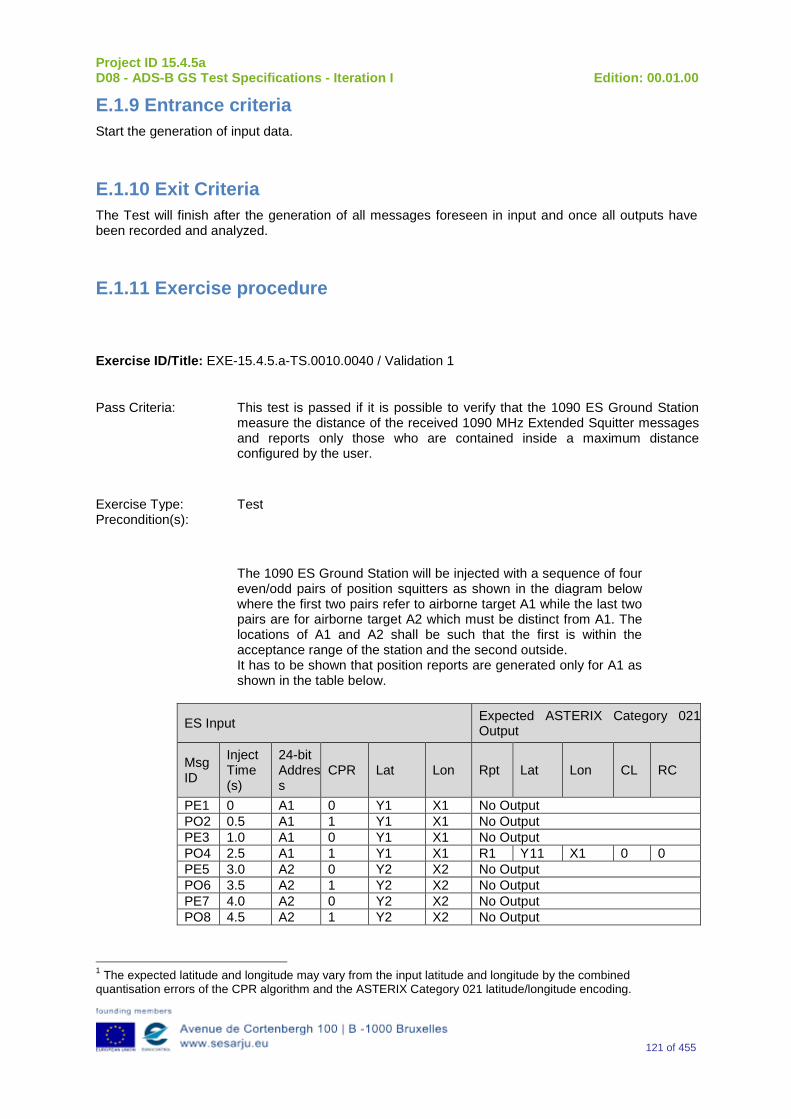
Project ID 15.4.5a D08 - ADS-B GS Test Specifications - Iteration I Edition: 00.01.00
121 of 455
E.1.9 Entrance criteria Start the generation of input data.
E.1.10 Exit Criteria The Test will finish after the generation of all messages foreseen in input and once all outputs have been recorded and analyzed.
E.1.11 Exercise procedure
Exercise ID/Title: EXE-15.4.5.a-TS.0010.0040 / Validation 1
Pass Criteria: This test is passed if it is possible to verify that the 1090 ES Ground Station measure the distance of the received 1090 MHz Extended Squitter messages and reports only those who are contained inside a maximum distance configured by the user.
Exercise Type: Test Precondition(s):
The 1090 ES Ground Station will be injected with a sequence of four even/odd pairs of position squitters as shown in the diagram below where the first two pairs refer to airborne target A1 while the last two pairs are for airborne target A2 which must be distinct from A1. The locations of A1 and A2 shall be such that the first is within the acceptance range of the station and the second outside. It has to be shown that position reports are generated only for A1 as shown in the table below.
ES Input Expected ASTERIX Category 021 Output
Msg ID
Inject Time (s)
24-bit Address
CPR Lat Lon Rpt Lat Lon CL RC
PE1 0 A1 0 Y1 X1 No Output PO2 0.5 A1 1 Y1 X1 No Output PE3 1.0 A1 0 Y1 X1 No Output PO4 2.5 A1 1 Y1 X1 R1 Y11 X1 0 0 PE5 3.0 A2 0 Y2 X2 No Output PO6 3.5 A2 1 Y2 X2 No Output PE7 4.0 A2 0 Y2 X2 No Output PO8 4.5 A2 1 Y2 X2 No Output
1 The expected latitude and longitude may vary from the input latitude and longitude by the combined quantisation errors of the CPR algorithm and the ASTERIX Category 021 latitude/longitude encoding.
Project ID 15.4.5a D08 - ADS-B GS Test Specifications - Iteration I Edition: 00.01.00
122 of 455
A1 and A2 can be any two distinct legal 24-bit Mode Addresses.
[Y1, X1] can be any lat/long position whose distance from the Ground Station location is less than CPRAirborneMaxRange and greater than CPRAirborneMaxRange – 0.5 nm.
[Y2, X2] can be any lat/long position whose distance from the Ground Station location is greater than CPRAirborneMaxRange but less than CPRAirborneMaxRange + 0.5 nm.
The timing of the messages for A2 (PE5 to PO8) may be shifted with regard to those for A1 (PE1 to PO4).
The above scenario will be repeated for additional targets at same ranges as A1 and A2 but displaced from them to bearings of +12, +22 and +45 degrees to ensure that the area being checked is round. More points may be included in scenario. Messages for each target may be interleaved or separated in time.
Note(s):
Device(s) in use: Ground Station ADS – B
Message Generator
ASTERIX Recording Tool
Power
UTC time Reference
Exercise Procedure:
Step Action Expected Reaction Pass/Fail Comment
1 Put the 1090GS in the default configuration.
2 In the 1090GS select Data driven reporting mode
3 Configure the recording tool to capture ASTERIX reports coming from the ADS-B GS.
4 Prepare the message source to play the scenario
5 Start recording ASTERIX reports.
Recording tool is receiving data from ADS-B GS
6 Play the scenario.
Recording tool is receiving data from ADS-B GS corresponding to test targets.
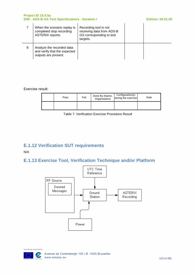
Project ID 15.4.5a D08 - ADS-B GS Test Specifications - Iteration I Edition: 00.01.00
123 of 455
7 When the scenario replay is completed stop recording ASTERIX reports.
Recording tool is not receiving data from ADS-B GS corresponding to test targets.
8 Analyze the recorded data and verify that the expected outputs are present.
Exercise result:
Pass Fail Done By (Name, Organisation)
Configuration(s) during the exercise Date
Table 7: Verification Exercise Procedure Result
E.1.12 Verification SUT requirements N/A
E.1.13 Exercise Tool, Verification Technique and/or Platform
Project ID 15.4.5a D08 - ADS-B GS Test Specifications - Iteration I Edition: 00.01.00
124 of 455
The Exercise will be verified in a platform with the following foreseen tools/equipment:
-Ground Station ADS – B
-Message Generator
-ASTERIX Recording Tool
-Power
-UTC time Reference
The Item reported above will be capable to perform the functionalities reported below.
Ground Station ADS - B
The primary function of the 1090 GS is to receive 1090 MHz Mode S Extended Squitter messages, extract the data contained therein, and create appropriated ASTERIX Category 21 and 23 Reports.
For this Exercise, the Ground Station ADS- B has to be provided with a specific functionality in order to perform a Central Processing (Central Processing Server) of Data coming from a lot of Remote Systems (ADS – B Ground Station or 1090 Receiver).
Message Generator
1090 MHz Extended Squitter messages in accordance to the format defined in DO260, DO260A and DO260b.
UTC Time Reference
The UTC Time reference is the solution adopted in the Test Scenario in order to provide the Synchronization in the Ground Station by UTC Time.
ASTERIX Recording Equipment
The ASTERIX recording equipment will be capable to record all ASTERIX reports sent from the 1090 ES Ground Station.
E.1.14 Verification Platform needs See section 3.5 Verification Platform Needs.
E.1.15 Platform Configuration N/A
E.1.16 Configuration(s) Identification of the Verification Platform N/A
E.1.17 Links to other Verification Exercises N/A
E.1.18 Representatively level/ limitations N/A
Project ID 15.4.5a D08 - ADS-B GS Test Specifications - Iteration I Edition: 00.01.00
125 of 455
E.2 Exercises Planning and management
E.2.1 Activities N/A
E.2.1.1 Preparatory activities Setup the tools/equipment listed in 3.5 and E.1.13 in order to meet the Test Preconditions
E.2.1.2 Execution activities Play the scenario generating in the input the desired messages and record the relevant ASTERIX output.
E.2.1.3 Post execution activities The post execution activities will be mainly focused on the analysis of recorded ASTERIX report during the application of each Scenario above. The Recorded ASTERIX report will be analyzed in order to verify the right information propagation as requested in each Test Scenario.
E.2.2 Human Resources. N/A
E.2.3 Responsibilities in the exercise N/A
E.2.4 Training N/A
E.2.5 Time planning N/A
E.2.6Risks. N/A
E.2.7 Errors and Observation handling N/A
E.3 Analysis Specification
E.3.1 Data collection methods The data’s collection during the test will be Qualitative.
E.3.2 Analysis method N/A
Project ID 15.4.5a D08 - ADS-B GS Test Specifications - Iteration I Edition: 00.01.00
126 of 455
E.3.3 Data logging requirements The data logging requirements for this scenario will foresee at least ASTERIX CAT 21 and ASTERIX CAT 23 item.
Project ID 15.4.5a D08 - ADS-B GS Test Specifications - Iteration I Edition: 00.01.00
127 of 455
Appendix F Verification Exercise EXE-15.04.05.a-TS.0010.0050 GS Validation 2
F.1Exercise Scope and Justification
F.1.1 Exercise Level The level of the exercise is functional.
F.1.2 Exercise Type The type of the exercise is Test.
F.1.3 Description of the system being addressed; ADS – B Ground Station.
F.1.4 Context of the verification exercise This document is applied to FAT (Factory acceptance Test).
F.1.5 Required Datasets 1090MHz Extended Squitter Messages input and 1090GS ASTERIX output.
F.1.6Verification objectives
Verify the Requirements related to the validation check.
This test needs to verify only those aspects of the CPR validation requirements that are necessary for ED-126 compliance. As a consequence, the test does not verify the processing of surface position messages or the creation of reports prior to the completion of the CPR validation test (e.g. for monitoring applications). This test procedure is applicable to Ground Station implementations that implement CPR decoding in accordance with DO-260A. Alternative CPR decoding implementations may require different procedures and scenarios to ensure compliance with ED129. Alternative tests must exercise the decoding algorithm at vulnerable points and should include two categories of test cases: normal range test cases and robustness (abnormal range) test cases.
OBJ-15.04.05.a-TS.0010.0001 The aim of this objective is to check that the “Ground ADS-B Receive” function receives ADS-B messages, decode, package and time-stamp the data, and send ADS-B Surveillance Reports to the ATC Processing System, i.e., the “Ground ADS-B Processing” function.
F.1.7Inputs 1090 MHz Extended Squitter messages in accordance to the format defined in DO260, DO260A and DO260B:
F.1.8 Outputs ASTERIX reports relevant to 1090 MHz Extended Squitter messages generated at input
Project ID 15.4.5a D08 - ADS-B GS Test Specifications - Iteration I Edition: 00.01.00
128 of 455
F.1.9 Entrance criteria Start the generation of input data.
F.1.10 Exit Criteria The Test will finish after the generation of all messages foreseen in the input and once all outputs have been recorded and analyzed.
F.1.11 Exercise procedure
Exercise ID/Title: EXE-15.4.5.a-TS.0010.0050 / Validation 2
Pass Criteria: This test is passed if it is possible to verify that the 1090 ES Ground Station decodes the received position information encoded using CPR format.
Note(s): Exercise Type: Test
Precondition(s):
The position messages used in each scenario must be airborne position messages (FTC = 9-18). The positions used in the first two messages must result in a global decode that passes the range check. To maximize test efficiency, the single target scenarios described below may be combined by giving each target a different announced address (AA) and interleaving the messages. The messages for each target in the combined scenario must have the same spacing in time as the corresponding messages in the individual scenarios.
The following definitions apply to this section
The latitude zone offset (in degrees) is:
( )( )
°=
6059360
LATZO
The longitude zone offset is:
( )( )
−
°=
1360
NLNLZOLON
Where NL is as defined in section A.1.7.2d of DO-260A.
The CPR bin width for latitude is:
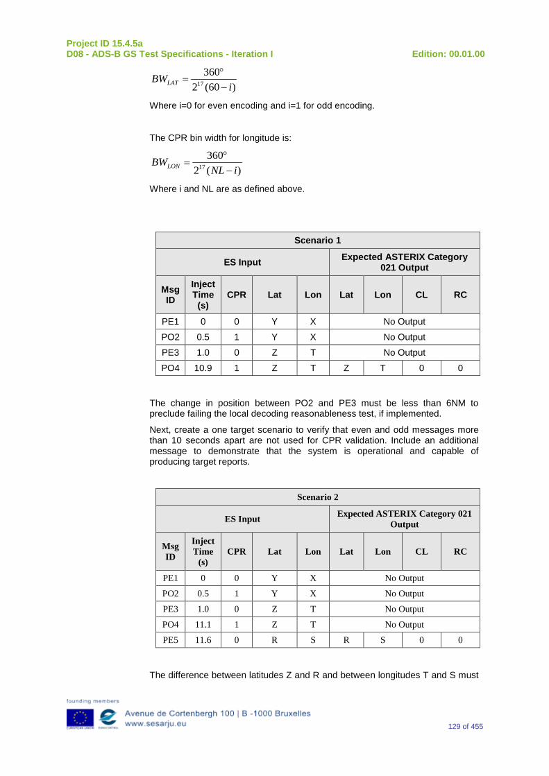
Project ID 15.4.5a D08 - ADS-B GS Test Specifications - Iteration I Edition: 00.01.00
129 of 455
)60(2360
17 iBWLAT −
°=
Where i=0 for even encoding and i=1 for odd encoding.
The CPR bin width for longitude is:
)(2360
17 iNLBWLON −
°=
Where i and NL are as defined above.
Scenario 1
ES Input Expected ASTERIX Category 021 Output
Msg ID
Inject Time (s)
CPR Lat Lon Lat Lon CL RC
PE1 0 0 Y X No Output
PO2 0.5 1 Y X No Output
PE3 1.0 0 Z T No Output
PO4 10.9 1 Z T Z T 0 0
The change in position between PO2 and PE3 must be less than 6NM to preclude failing the local decoding reasonableness test, if implemented.
Next, create a one target scenario to verify that even and odd messages more than 10 seconds apart are not used for CPR validation. Include an additional message to demonstrate that the system is operational and capable of producing target reports.
Scenario 2
ES Input Expected ASTERIX Category 021 Output
Msg ID
Inject Time
(s) CPR Lat Lon Lat Lon CL RC
PE1 0 0 Y X No Output
PO2 0.5 1 Y X No Output
PE3 1.0 0 Z T No Output
PO4 11.1 1 Z T No Output
PE5 11.6 0 R S R S 0 0
The difference between latitudes Z and R and between longitudes T and S must
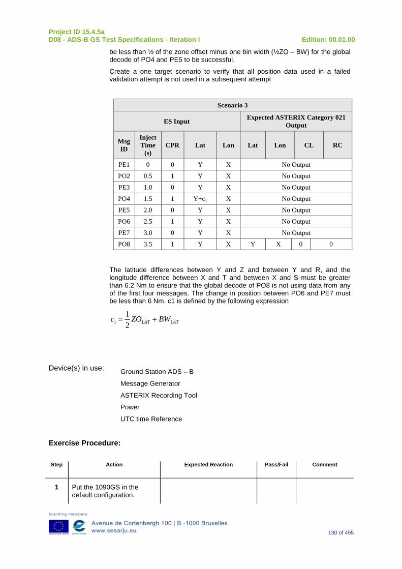
Project ID 15.4.5a D08 - ADS-B GS Test Specifications - Iteration I Edition: 00.01.00
130 of 455
be less than ½ of the zone offset minus one bin width (½ZO – BW) for the global decode of PO4 and PE5 to be successful.
Create a one target scenario to verify that all position data used in a failed validation attempt is not used in a subsequent attempt
Scenario 3
ES Input Expected ASTERIX Category 021 Output
Msg ID
Inject Time
(s) CPR Lat Lon Lat Lon CL RC
PE1 0 0 Y X No Output
PO2 0.5 1 Y X No Output
PE3 1.0 0 Y X No Output
PO4 1.5 1 Y+c1 X No Output
PE5 2.0 0 Y X No Output
PO6 2.5 1 Y X No Output
PE7 3.0 0 Y X No Output
PO8 3.5 1 Y X Y X 0 0
The latitude differences between Y and Z and between Y and R, and the longitude difference between X and T and between X and S must be greater than 6.2 Nm to ensure that the global decode of PO8 is not using data from any of the first four messages. The change in position between PO6 and PE7 must be less than 6 Nm. c1 is defined by the following expression
LATLAT BWZOc +=21
1
Device(s) in use: Ground Station ADS – B
Message Generator
ASTERIX Recording Tool
Power
UTC time Reference
Exercise Procedure:
Step Action Expected Reaction Pass/Fail Comment
1 Put the 1090GS in the default configuration.
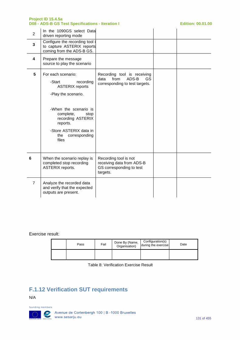
Project ID 15.4.5a D08 - ADS-B GS Test Specifications - Iteration I Edition: 00.01.00
131 of 455
2 In the 1090GS select Data driven reporting mode
3 Configure the recording tool i to capture ASTERIX reports coming from the ADS-B GS.
4 Prepare the message source to play the scenario
5 For each scenario:
-Start recording ASTERIX reports
-Play the scenario.
-When the scenario is complete, stop recording ASTERIX reports.
-Store ASTERIX data in the corresponding files
Recording tool is receiving data from ADS-B GS corresponding to test targets.
6 When the scenario replay is completed stop recording ASTERIX reports.
Recording tool is not receiving data from ADS-B GS corresponding to test targets.
7 Analyze the recorded data and verify that the expected outputs are present.
Exercise result:
Pass Fail Done By (Name, Organisation)
Configuration(s) during the exercise Date
Table 8: Verification Exercise Result
F.1.12 Verification SUT requirements N/A
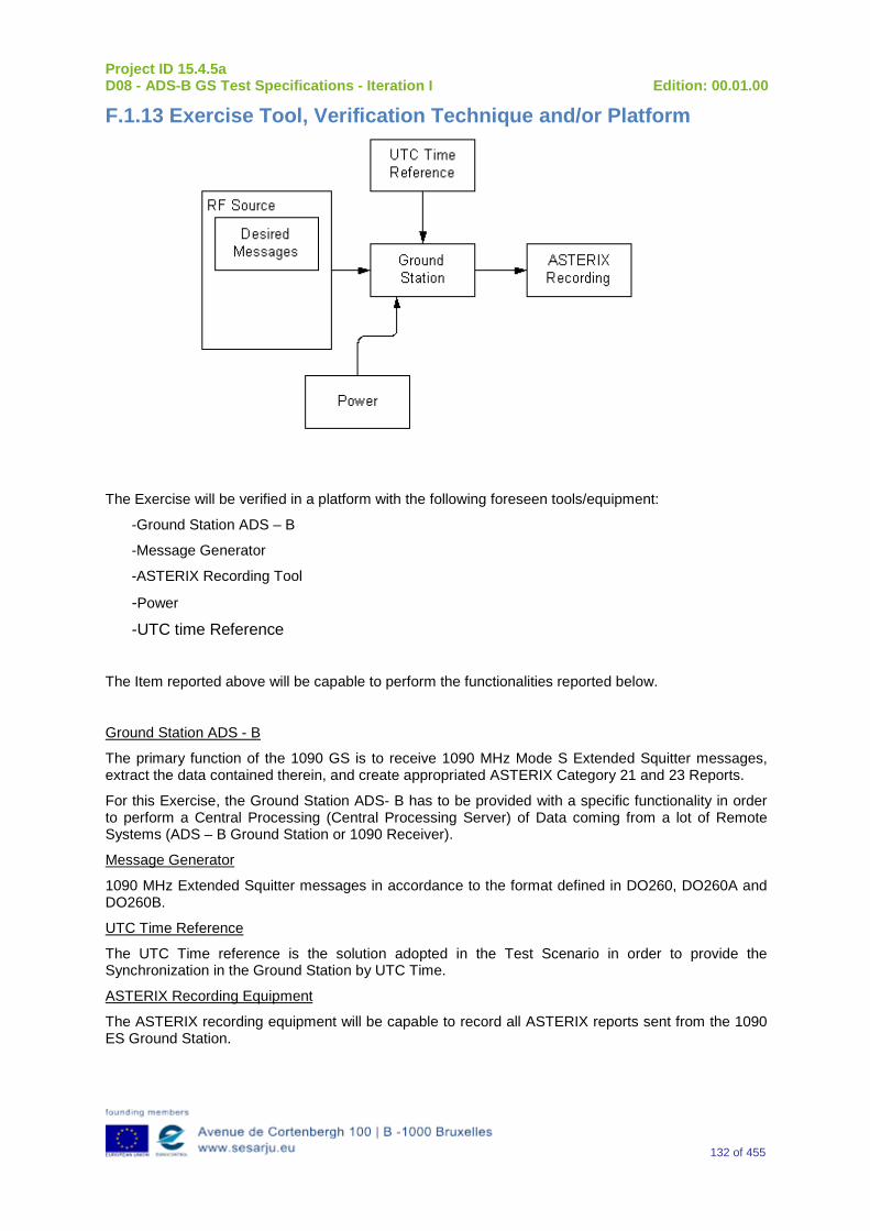
Project ID 15.4.5a D08 - ADS-B GS Test Specifications - Iteration I Edition: 00.01.00
132 of 455
F.1.13 Exercise Tool, Verification Technique and/or Platform
The Exercise will be verified in a platform with the following foreseen tools/equipment:
-Ground Station ADS – B
-Message Generator
-ASTERIX Recording Tool
-Power -UTC time Reference
The Item reported above will be capable to perform the functionalities reported below.
Ground Station ADS - B
The primary function of the 1090 GS is to receive 1090 MHz Mode S Extended Squitter messages, extract the data contained therein, and create appropriated ASTERIX Category 21 and 23 Reports.
For this Exercise, the Ground Station ADS- B has to be provided with a specific functionality in order to perform a Central Processing (Central Processing Server) of Data coming from a lot of Remote Systems (ADS – B Ground Station or 1090 Receiver).
Message Generator
1090 MHz Extended Squitter messages in accordance to the format defined in DO260, DO260A and DO260B.
UTC Time Reference
The UTC Time reference is the solution adopted in the Test Scenario in order to provide the Synchronization in the Ground Station by UTC Time.
ASTERIX Recording Equipment
The ASTERIX recording equipment will be capable to record all ASTERIX reports sent from the 1090 ES Ground Station.
Project ID 15.4.5a D08 - ADS-B GS Test Specifications - Iteration I Edition: 00.01.00
133 of 455
F.1.14 Verification Platform needs See section 3.5 Verification Platform Needs.
F.1.15 Platform Configuration N/A
F.1.16 Configuration(s) Identification of the Verification Platform N/A
F.1.17 Links to other Verification Exercises N/A
F.1.18 Representatively level/ limitations N/A
F.2 Exercises Planning and management
F.2.1 Activities N/A
F.2.1.1 Preparatory activities Setup the tools/equipment listed in 3.5 and F.1.13 in order to meet the Test Preconditions
F.2.1.2 Execution activities Play the scenario generating in the input the desired messages and record the relevant ASTERIX output.
F.2.1.3 Post execution activities The post execution activities will be mainly focused on the analysis of recorded ASTERIX report during the application of each Scenario above. The Recorded ASTERIX report will be analyzed in order to verify the right information propagation as requested in each Test Scenario.
F.2.2 Human Resources. N/A
F.2.3 Responsibilities in the exercise N/A
F.2.4 Training N/A
F.2.5 Time planning N/A
Project ID 15.4.5a D08 - ADS-B GS Test Specifications - Iteration I Edition: 00.01.00
134 of 455
F.2.6 Risks. N/A
F.2.7 Errors and Observation handling N/A
F.3 Analysis Specification
F.3.1 Data collection methods The data’s collection during the test will be Qualitative.
F.3.2 Analysis method N/A
F.3.3 Data logging requirements The data logging requirements for this scenario will foresee at least ASTERIX CAT 21 and ASTERIX CAT 23 item.
Project ID 15.4.5a D08 - ADS-B GS Test Specifications - Iteration I Edition: 00.01.00
135 of 455
Appendix G Verification Exercise EXE-15.04.05.a-TS.0010.0060 GS Data Item Inclusion
G.1Exercise Scope and Justification
G.1.1 Exercise Level The level of the exercise is functional.
G.1.2 Exercise Type The type of this exercise is Test.
G.1.3 Description of the system being addressed; Ground Station ADS –B.
G.1.4 Context of the verification exercise This document is applied to FAT (Factory Acceptance Test).
G.1.5 Required Datasets 1090MHz Extended Squitter Messages input and 1090GS ASTERIX output.
G.1.6 Verification objectives Verify the following:
Verify that if the validation tests are passed, the 1090 GS shall package and timestamp the decoded data into a target report in ATX 21 form.
Verify that the 1090 GS forwards the compiled ATX21 target reports to client systems over a data network
Verify that the 1090 GS reports the following minimum data set per target report to the ATC Processing system:
Aircraft Horizontal Position – Latitude and Longitude);
Pressure altitude
Quality Indications of Horizontal Position
Aircraft Identity (a/c identification and Mode A code)
Emergency Indicators
Special Position Identification (SPI)
Time of Applicability
The 1090 GS provides in each target report a time of applicability of the position information
The 1009 GS shall provide separate times of applicability for any specific data items, who’s ToA differs from that of the position
OBJ-15.04.05.a-TS.0010.0001 The aim of this objective is to check that the “Ground ADS-B Receive” function receives ADS-B messages, decode, package and time-stamp the data, and send ADS-B Surveillance Reports to the ATC Processing System, i.e., the “Ground ADS-B Processing” function.
Project ID 15.4.5a D08 - ADS-B GS Test Specifications - Iteration I Edition: 00.01.00
136 of 455
OBJ-15.04.05.a-TS.0010.0002 The aim of this objective is to check that the “Ground ADS-B Receive” function provides the following minimum data set to the ATC Processing system: • Aircraft Horizontal Position – Latitude and Longitude; • Pressure altitude ; • Quality Indications of Horizontal Position ; • Aircraft Identity ; Emergency Indicators ; • Special Position Identification ; • Time of Applicability. NOTE: Emergency Indicators and SPI are provided only when selected by the flight crew.
OBJ-15.04.05.a-TS.0010.0003 The aim of this objective is to check that when direct recognition procedures are used by the ATCO for identification, the ADS-B Ground Domain contains a function to ensure the aircraft identity data that is broadcast is retained and correctly associated with the position information for display, Aircraft Identity Retain OBJ-15.04.05.a-TS.0010.0004 The aim of this objective is to check that the “Ground ADS-B Receive” function provides in each ADS-B surveillance report a time of applicability (Interface E2) of the position information Time Of Applicability provision OBJ-15.04.05.a-TS.0010.0005 The aim of this objective is to check that If the time of applicability within each ADS-B surveillance report is not applicable for all data items of that report (interface E2), the “Ground ADS-B Receive” function provides separate times of applicability for the specific data items that differ, OBJ-15.04.05.a-TS.0010.0006 The aim of this objective is to check that the “Ground ADS-B Surveillance Processing” function time-registers the asynchronously received ADS-B position updates from ADS-B-equipped aircraft
G.1.7 Inputs 1090 MHz Extended Squitter messages in accordance to the format defined in DO260, DO260A and, DO260B:
G.1.8 Outputs ASTERIX reports relevant to 1090 MHz Extended Squitter messages generated in the input.
G.1.9 Entrance criteria Start the generation of 1090 MHz Extended Squitter messages set as indicated in the table below.
G.1.10 Exit Criteria The Test will finish after the generation of all messages foreseen in the input and once all outputs have been recorded and analyzed.
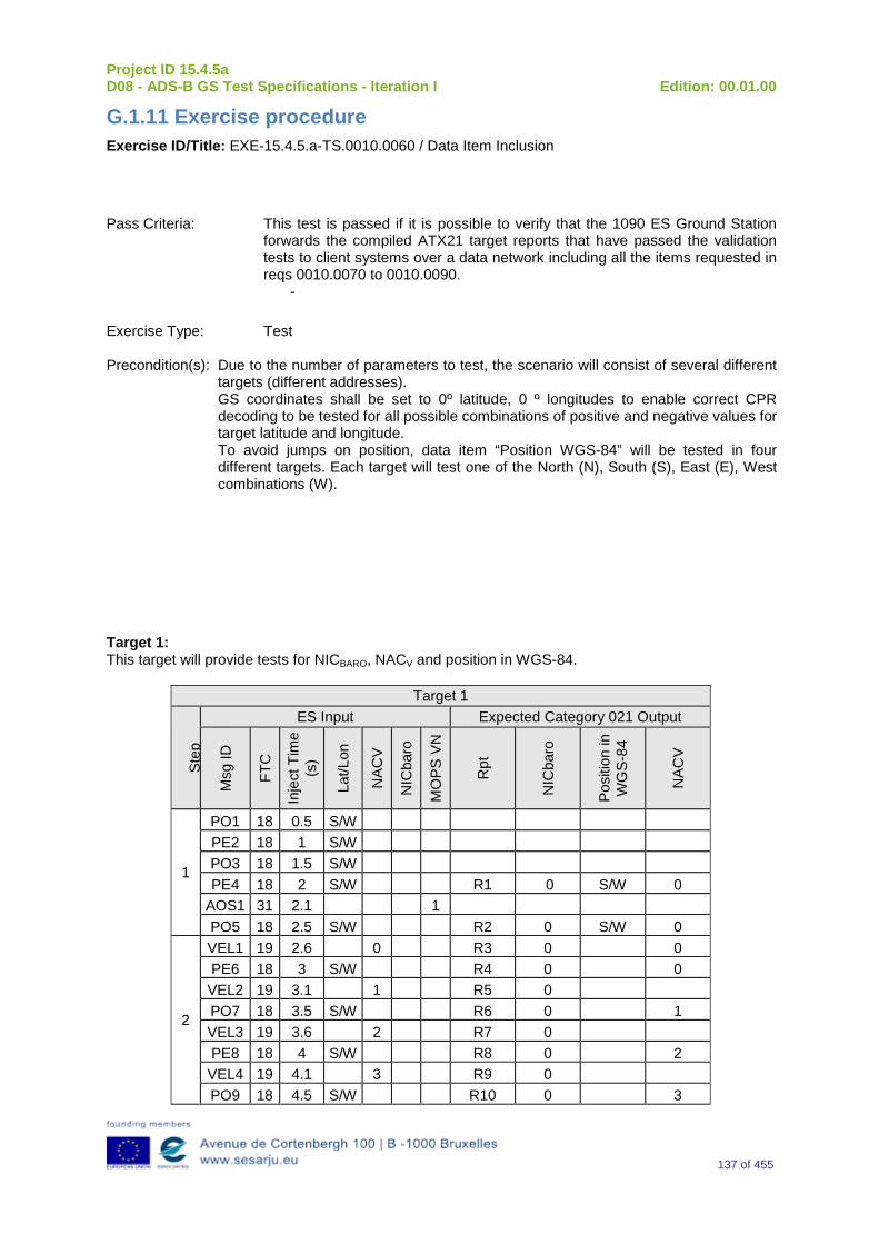
Project ID 15.4.5a D08 - ADS-B GS Test Specifications - Iteration I Edition: 00.01.00
137 of 455
G.1.11 Exercise procedure Exercise ID/Title: EXE-15.4.5.a-TS.0010.0060 / Data Item Inclusion
Pass Criteria: This test is passed if it is possible to verify that the 1090 ES Ground Station forwards the compiled ATX21 target reports that have passed the validation tests to client systems over a data network including all the items requested in reqs 0010.0070 to 0010.0090.
-
Exercise Type: Test Precondition(s): Due to the number of parameters to test, the scenario will consist of several different
targets (different addresses). GS coordinates shall be set to 0º latitude, 0 º longitudes to enable correct CPR decoding to be tested for all possible combinations of positive and negative values for target latitude and longitude. To avoid jumps on position, data item “Position WGS-84” will be tested in four different targets. Each target will test one of the North (N), South (S), East (E), West combinations (W).
Target 1: This target will provide tests for NICBARO, NACV and position in WGS-84.
Target 1
St
ep
ES Input Expected Category 021 Output
Msg
ID
FTC
Inje
ct T
ime
(s)
Lat/L
on
NAC
V
NIC
baro
MO
PS V
N
Rpt
NIC
baro
Posi
tion
in
WG
S-84
NAC
V
1
PO1 18 0.5 S/W PE2 18 1 S/W PO3 18 1.5 S/W PE4 18 2 S/W R1 0 S/W 0
AOS1 31 2.1 1 PO5 18 2.5 S/W R2 0 S/W 0
2
VEL1 19 2.6 0 R3 0 0 PE6 18 3 S/W R4 0 0 VEL2 19 3.1 1 R5 0 PO7 18 3.5 S/W R6 0 1 VEL3 19 3.6 2 R7 0 PE8 18 4 S/W R8 0 2 VEL4 19 4.1 3 R9 0 PO9 18 4.5 S/W R10 0 3
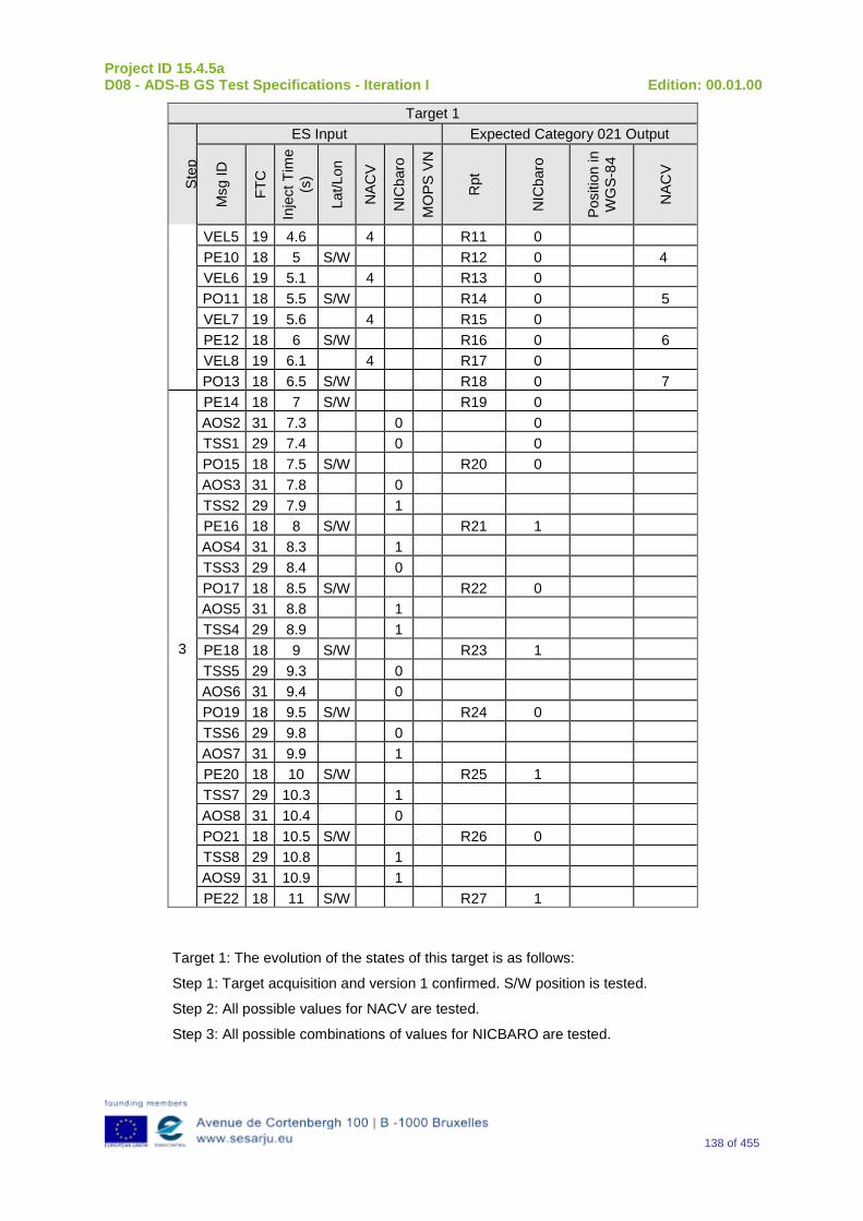
Project ID 15.4.5a D08 - ADS-B GS Test Specifications - Iteration I Edition: 00.01.00
138 of 455
Target 1
St
ep
ES Input Expected Category 021 Output
Msg
ID
FTC
Inje
ct T
ime
(s)
Lat/L
on
NAC
V
NIC
baro
MO
PS V
N
Rpt
NIC
baro
Posi
tion
in
WG
S-84
NAC
V
VEL5 19 4.6 4 R11 0 PE10 18 5 S/W R12 0 4 VEL6 19 5.1 4 R13 0 PO11 18 5.5 S/W R14 0 5 VEL7 19 5.6 4 R15 0 PE12 18 6 S/W R16 0 6 VEL8 19 6.1 4 R17 0 PO13 18 6.5 S/W R18 0 7
3
PE14 18 7 S/W R19 0 AOS2 31 7.3 0 0 TSS1 29 7.4 0 0 PO15 18 7.5 S/W R20 0 AOS3 31 7.8 0 TSS2 29 7.9 1 PE16 18 8 S/W R21 1 AOS4 31 8.3 1 TSS3 29 8.4 0 PO17 18 8.5 S/W R22 0 AOS5 31 8.8 1 TSS4 29 8.9 1 PE18 18 9 S/W R23 1 TSS5 29 9.3 0 AOS6 31 9.4 0 PO19 18 9.5 S/W R24 0 TSS6 29 9.8 0 AOS7 31 9.9 1 PE20 18 10 S/W R25 1 TSS7 29 10.3 1 AOS8 31 10.4 0 PO21 18 10.5 S/W R26 0 TSS8 29 10.8 1 AOS9 31 10.9 1 PE22 18 11 S/W R27 1
Target 1: The evolution of the states of this target is as follows:
Step 1: Target acquisition and version 1 confirmed. S/W position is tested.
Step 2: All possible values for NACV are tested.
Step 3: All possible combinations of values for NICBARO are tested.
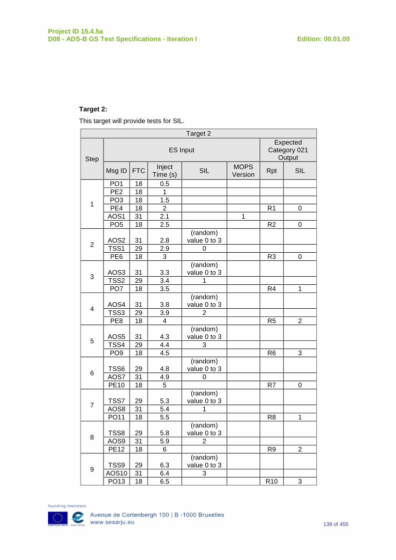
Project ID 15.4.5a D08 - ADS-B GS Test Specifications - Iteration I Edition: 00.01.00
139 of 455
Target 2:
This target will provide tests for SIL.
Target 2
Step ES Input
Expected Category 021
Output
Msg ID FTC Inject Time (s) SIL MOPS
Version Rpt SIL
1
PO1 18 0.5 PE2 18 1 PO3 18 1.5 PE4 18 2 R1 0
AOS1 31 2.1 1 PO5 18 2.5 R2 0
2 AOS2 31 2.8 (random)
value 0 to 3 TSS1 29 2.9 0 PE6 18 3 R3 0
3 AOS3 31 3.3 (random)
value 0 to 3 TSS2 29 3.4 1 PO7 18 3.5 R4 1
4 AOS4 31 3.8 (random)
value 0 to 3 TSS3 29 3.9 2 PE8 18 4 R5 2
5 AOS5 31 4.3 (random)
value 0 to 3 TSS4 29 4.4 3 PO9 18 4.5 R6 3
6 TSS6 29 4.8 (random)
value 0 to 3 AOS7 31 4.9 0 PE10 18 5 R7 0
7 TSS7 29 5.3 (random)
value 0 to 3 AOS8 31 5.4 1 PO11 18 5.5 R8 1
8 TSS8 29 5.8 (random)
value 0 to 3 AOS9 31 5.9 2 PE12 18 6 R9 2
9 TSS9 29 6.3 (random)
value 0 to 3 AOS10 31 6.4 3 PO13 18 6.5 R10 3
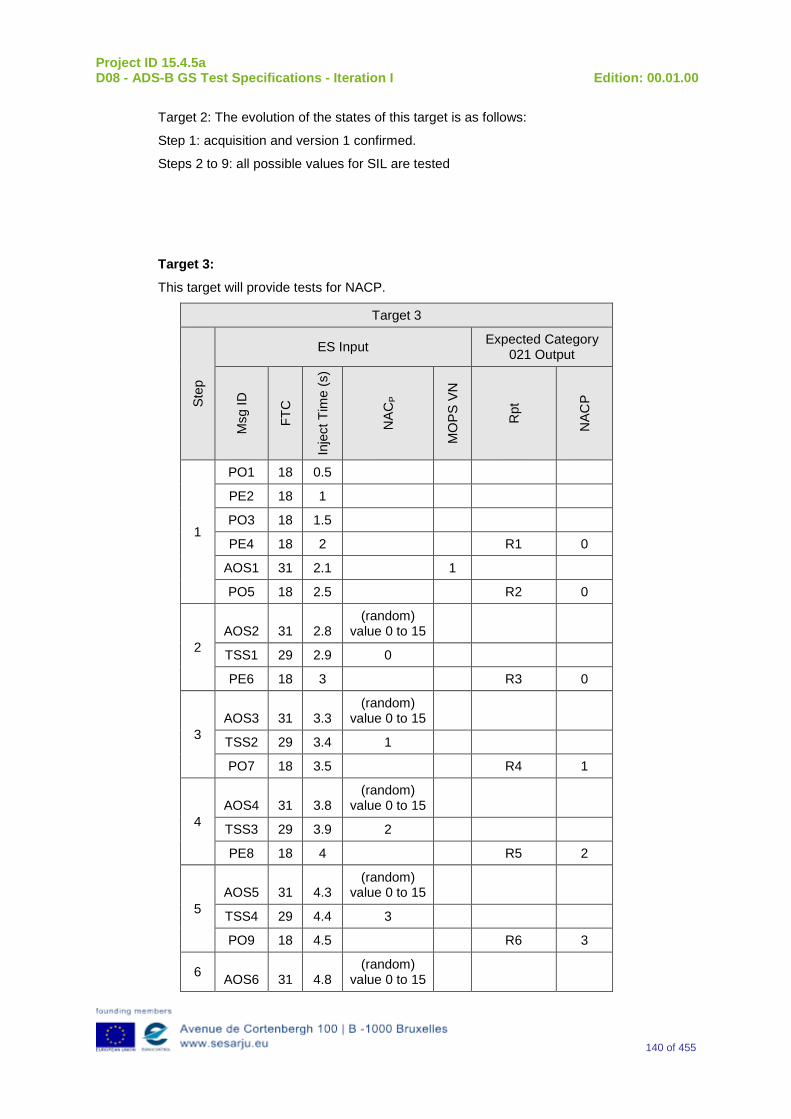
Project ID 15.4.5a D08 - ADS-B GS Test Specifications - Iteration I Edition: 00.01.00
140 of 455
Target 2: The evolution of the states of this target is as follows:
Step 1: acquisition and version 1 confirmed.
Steps 2 to 9: all possible values for SIL are tested
Target 3:
This target will provide tests for NACP.
Target 3
Step
ES Input Expected Category 021 Output
Msg
ID
FTC
Inje
ct T
ime
(s)
NAC
P
MO
PS V
N
Rpt
NAC
P
1
PO1 18 0.5
PE2 18 1
PO3 18 1.5
PE4 18 2 R1 0
AOS1 31 2.1 1
PO5 18 2.5 R2 0
2 AOS2 31 2.8
(random) value 0 to 15
TSS1 29 2.9 0
PE6 18 3 R3 0
3 AOS3 31 3.3
(random) value 0 to 15
TSS2 29 3.4 1
PO7 18 3.5 R4 1
4 AOS4 31 3.8
(random) value 0 to 15
TSS3 29 3.9 2
PE8 18 4 R5 2
5 AOS5 31 4.3
(random) value 0 to 15
TSS4 29 4.4 3
PO9 18 4.5 R6 3
6 AOS6 31 4.8 (random)
value 0 to 15
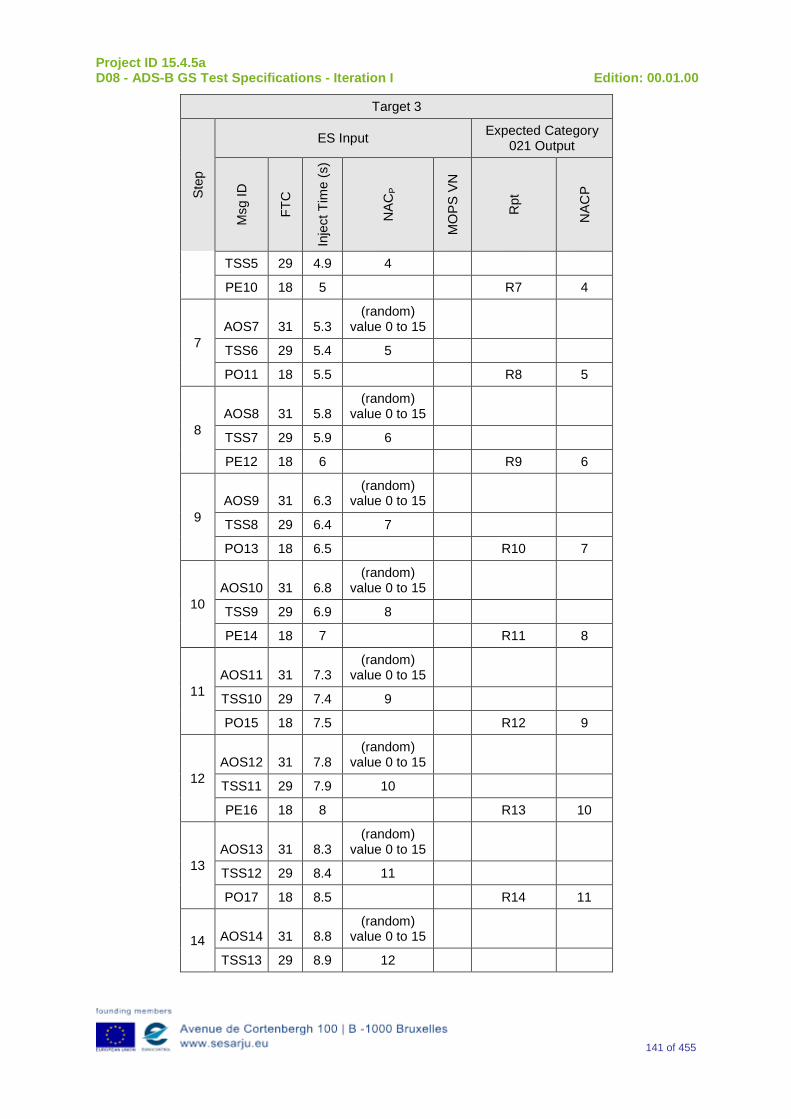
Project ID 15.4.5a D08 - ADS-B GS Test Specifications - Iteration I Edition: 00.01.00
141 of 455
Target 3
Step
ES Input Expected Category 021 Output
Msg
ID
FTC
Inje
ct T
ime
(s)
NAC
P
MO
PS V
N
Rpt
NAC
P
TSS5 29 4.9 4
PE10 18 5 R7 4
7 AOS7 31 5.3
(random) value 0 to 15
TSS6 29 5.4 5
PO11 18 5.5 R8 5
8 AOS8 31 5.8
(random) value 0 to 15
TSS7 29 5.9 6
PE12 18 6 R9 6
9 AOS9 31 6.3
(random) value 0 to 15
TSS8 29 6.4 7
PO13 18 6.5 R10 7
10 AOS10 31 6.8
(random) value 0 to 15
TSS9 29 6.9 8
PE14 18 7 R11 8
11 AOS11 31 7.3
(random) value 0 to 15
TSS10 29 7.4 9
PO15 18 7.5 R12 9
12 AOS12 31 7.8
(random) value 0 to 15
TSS11 29 7.9 10
PE16 18 8 R13 10
13 AOS13 31 8.3
(random) value 0 to 15
TSS12 29 8.4 11
PO17 18 8.5 R14 11
14 AOS14 31 8.8 (random)
value 0 to 15
TSS13 29 8.9 12
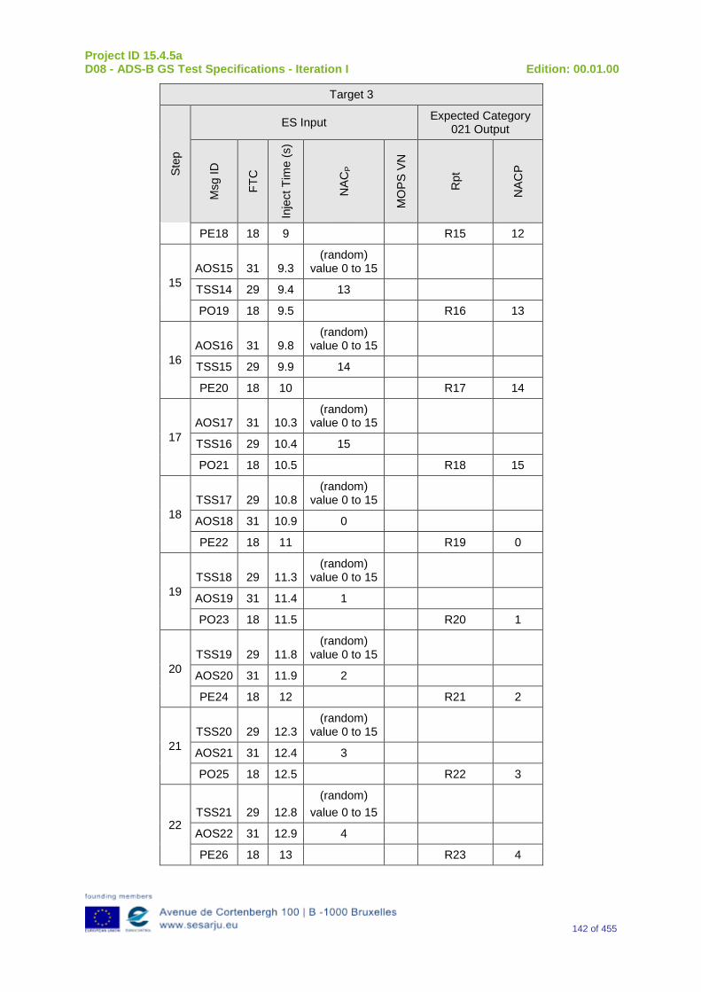
Project ID 15.4.5a D08 - ADS-B GS Test Specifications - Iteration I Edition: 00.01.00
142 of 455
Target 3
Step
ES Input Expected Category 021 Output
Msg
ID
FTC
Inje
ct T
ime
(s)
NAC
P
MO
PS V
N
Rpt
NAC
P
PE18 18 9 R15 12
15 AOS15 31 9.3
(random) value 0 to 15
TSS14 29 9.4 13
PO19 18 9.5 R16 13
16 AOS16 31 9.8
(random) value 0 to 15
TSS15 29 9.9 14
PE20 18 10 R17 14
17 AOS17 31 10.3
(random) value 0 to 15
TSS16 29 10.4 15
PO21 18 10.5 R18 15
18 TSS17 29 10.8
(random) value 0 to 15
AOS18 31 10.9 0
PE22 18 11 R19 0
19 TSS18 29 11.3
(random) value 0 to 15
AOS19 31 11.4 1
PO23 18 11.5 R20 1
20 TSS19 29 11.8
(random) value 0 to 15
AOS20 31 11.9 2
PE24 18 12 R21 2
21 TSS20 29 12.3
(random) value 0 to 15
AOS21 31 12.4 3
PO25 18 12.5 R22 3
22 TSS21 29 12.8
(random) value 0 to 15
AOS22 31 12.9 4
PE26 18 13 R23 4
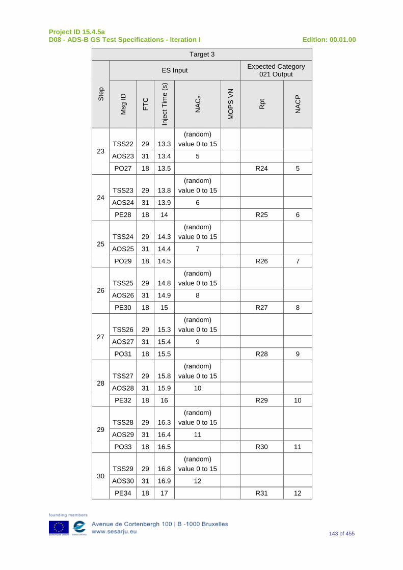
Project ID 15.4.5a D08 - ADS-B GS Test Specifications - Iteration I Edition: 00.01.00
143 of 455
Target 3
Step
ES Input Expected Category 021 Output
Msg
ID
FTC
Inje
ct T
ime
(s)
NAC
P
MO
PS V
N
Rpt
NAC
P
23 TSS22 29 13.3
(random) value 0 to 15
AOS23 31 13.4 5
PO27 18 13.5 R24 5
24 TSS23 29 13.8
(random) value 0 to 15
AOS24 31 13.9 6
PE28 18 14 R25 6
25 TSS24 29 14.3
(random) value 0 to 15
AOS25 31 14.4 7
PO29 18 14.5 R26 7
26 TSS25 29 14.8
(random) value 0 to 15
AOS26 31 14.9 8
PE30 18 15 R27 8
27 TSS26 29 15.3
(random) value 0 to 15
AOS27 31 15.4 9
PO31 18 15.5 R28 9
28 TSS27 29 15.8
(random) value 0 to 15
AOS28 31 15.9 10
PE32 18 16 R29 10
29 TSS28 29 16.3
(random) value 0 to 15
AOS29 31 16.4 11
PO33 18 16.5 R30 11
30 TSS29 29 16.8
(random) value 0 to 15
AOS30 31 16.9 12
PE34 18 17 R31 12
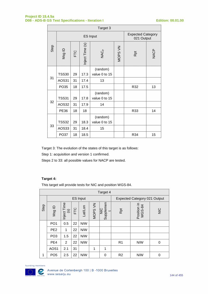
Project ID 15.4.5a D08 - ADS-B GS Test Specifications - Iteration I Edition: 00.01.00
144 of 455
Target 3
Step
ES Input Expected Category 021 Output
Msg
ID
FTC
Inje
ct T
ime
(s)
NAC
P
MO
PS V
N
Rpt
NAC
P
31 TSS30 29 17.3
(random) value 0 to 15
AOS31 31 17.4 13
PO35 18 17.5 R32 13
32 TSS31 29 17.8
(random) value 0 to 15
AOS32 31 17.9 14
PE36 18 18 R33 14
33 TSS32 29 18.3
(random) value 0 to 15
AOS33 31 18.4 15
PO37 18 18.5 R34 15
Target 3: The evolution of the states of this target is as follows:
Step 1: acquisition and version 1 confirmed.
Steps 2 to 33: all possible values for NACP are tested.
Target 4:
This target will provide tests for NIC and position WGS-84.
Target 4
Step
ES Input Expected Category 021 Output
Msg
ID
Inje
ct T
ime
(s)
FTC
Lat/L
on
MO
PS V
N
NIC
Su
pple
men
t Rpt
Posi
tion
in
WG
S-84
NIC
1
PO1 0.5 22 N/W
PE2 1 22 N/W
PO3 1.5 22 N/W
PE4 2 22 N/W R1 N/W 0
AOS1 2.1 31 1 1
PO5 2.5 22 N/W 0 R2 N/W 0
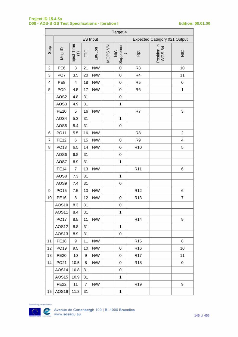
Project ID 15.4.5a D08 - ADS-B GS Test Specifications - Iteration I Edition: 00.01.00
145 of 455
Target 4
Step
ES Input Expected Category 021 Output
Msg
ID
Inje
ct T
ime
(s)
FTC
Lat/L
on
MO
PS V
N
NIC
Su
pple
men
t Rpt
Posi
tion
in
WG
S-84
NIC
2 PE6 3 21 N/W 0 R3 10
3 PO7 3.5 20 N/W 0 R4 11
4 PE8 4 18 N/W 0 R5 0
5 PO9 4.5 17 N/W 0 R6 1
6
AOS2 4.8 31 0
AOS3 4.9 31 1
PE10 5 16 N/W R7 3
AOS4 5.3 31 1
AOS5 5.4 31 0
PO11 5.5 16 N/W R8 2
7 PE12 6 15 N/W 0 R9 4
8 PO13 6.5 14 N/W 0 R10 5
9
AOS6 6.8 31 0
AOS7 6.9 31 1
PE14 7 13 N/W R11 6
AOS8 7.3 31 1
AOS9 7.4 31 0
PO15 7.5 13 N/W R12 6
10 PE16 8 12 N/W 0 R13 7
11
AOS10 8.3 31 0
AOS11 8.4 31 1
PO17 8.5 11 N/W R14 9
AOS12 8.8 31 1
AOS13 8.9 31 0
PE18 9 11 N/W R15 8
12 PO19 9.5 10 N/W 0 R16 10
13 PE20 10 9 N/W 0 R17 11
14 PO21 10.5 8 N/W 0 R18 0
15
AOS14 10.8 31 0
AOS15 10.9 31 1
PE22 11 7 N/W R19 9
AOS16 11.3 31 1
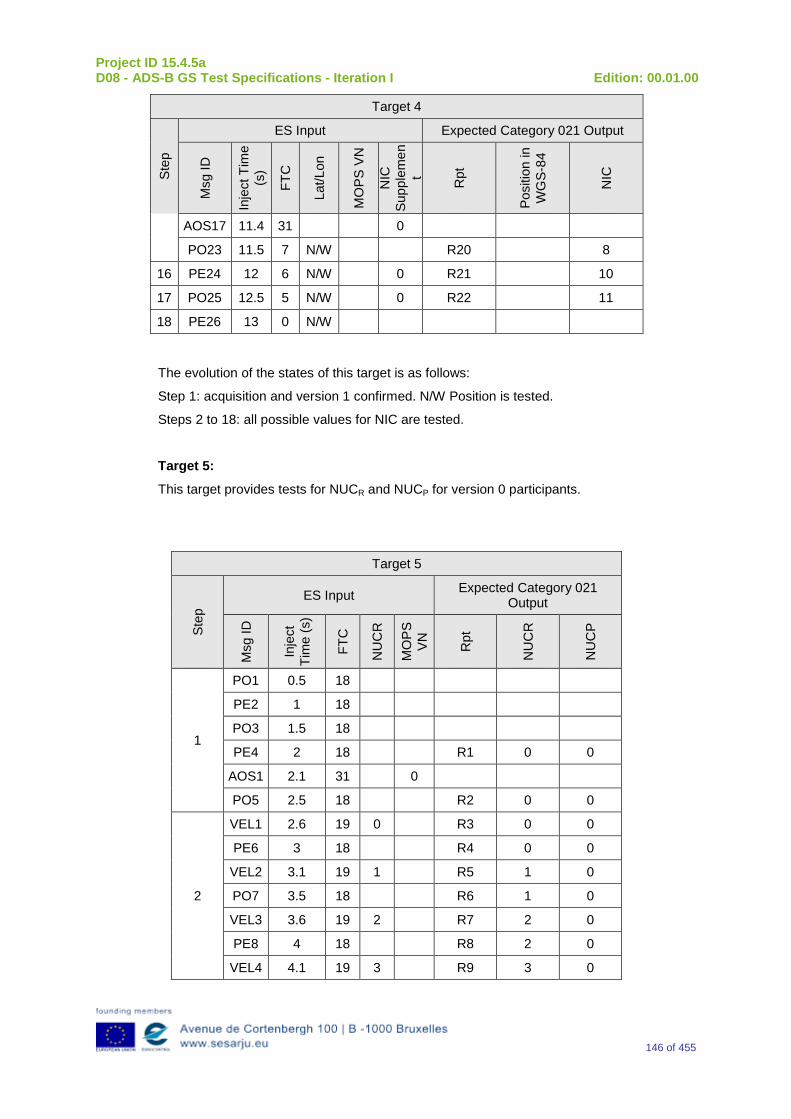
Project ID 15.4.5a D08 - ADS-B GS Test Specifications - Iteration I Edition: 00.01.00
146 of 455
Target 4
Step
ES Input Expected Category 021 Output
Msg
ID
Inje
ct T
ime
(s)
FTC
Lat/L
on
MO
PS V
N
NIC
Su
pple
men
t Rpt
Posi
tion
in
WG
S-84
NIC
AOS17 11.4 31 0
PO23 11.5 7 N/W R20 8
16 PE24 12 6 N/W 0 R21 10
17 PO25 12.5 5 N/W 0 R22 11
18 PE26 13 0 N/W
The evolution of the states of this target is as follows:
Step 1: acquisition and version 1 confirmed. N/W Position is tested.
Steps 2 to 18: all possible values for NIC are tested.
Target 5:
This target provides tests for NUCR and NUCP for version 0 participants.
Target 5
Step
ES Input Expected Category 021 Output
Msg
ID
Inje
ct
Tim
e (s
)
FTC
NU
CR
MO
PS
VN
Rpt
NU
CR
NU
CP
1
PO1 0.5 18
PE2 1 18
PO3 1.5 18
PE4 2 18 R1 0 0
AOS1 2.1 31 0
PO5 2.5 18 R2 0 0
2
VEL1 2.6 19 0 R3 0 0
PE6 3 18 R4 0 0
VEL2 3.1 19 1 R5 1 0
PO7 3.5 18 R6 1 0
VEL3 3.6 19 2 R7 2 0
PE8 4 18 R8 2 0
VEL4 4.1 19 3 R9 3 0
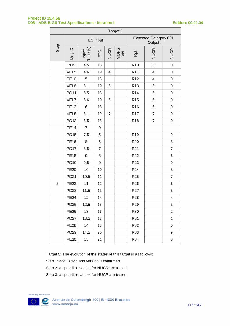
Project ID 15.4.5a D08 - ADS-B GS Test Specifications - Iteration I Edition: 00.01.00
147 of 455
Target 5
Step
ES Input Expected Category 021 Output
Msg
ID
Inje
ct
Tim
e (s
)
FTC
NU
CR
MO
PS
VN
Rpt
NU
CR
NU
CP
PO9 4.5 18 R10 3 0
VEL5 4.6 19 4 R11 4 0
PE10 5 18 R12 4 0
VEL6 5.1 19 5 R13 5 0
PO11 5.5 18 R14 5 0
VEL7 5.6 19 6 R15 6 0
PE12 6 18 R16 6 0
VEL8 6.1 19 7 R17 7 0
PO13 6.5 18 R18 7 0
3
PE14 7 0
PO15 7.5 5 R19 9
PE16 8 6 R20 8
PO17 8.5 7 R21 7
PE18 9 8 R22 6
PO19 9.5 9 R23 9
PE20 10 10 R24 8
PO21 10.5 11 R25 7
PE22 11 12 R26 6
PO23 11.5 13 R27 5
PE24 12 14 R28 4
PO25 12,5 15 R29 3
PE26 13 16 R30 2
PO27 13.5 17 R31 1
PE28 14 18 R32 0
PO29 14.5 20 R33 9
PE30 15 21 R34 8
Target 5: The evolution of the states of this target is as follows:
Step 1: acquisition and version 0 confirmed.
Step 2: all possible values for NUCR are tested
Step 3: all possible values for NUCP are tested
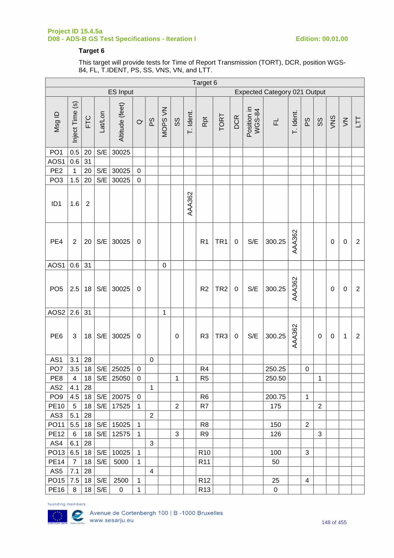
Project ID 15.4.5a D08 - ADS-B GS Test Specifications - Iteration I Edition: 00.01.00
148 of 455
Target 6
This target will provide tests for Time of Report Transmission (TORT), DCR, position WGS-84, FL, T.IDENT, PS, SS, VNS, VN, and LTT.
Target 6 ES Input Expected Category 021 Output
Msg
ID
Inje
ct T
ime
(s)
FTC
Lat/L
on
Altit
ude
(feet
)
Q
PS
MO
PS V
N
SS
T. Id
ent.
Rpt
TOR
T
DC
R
Posi
tion
in
WG
S-84
FL
T. Id
ent.
PS
SS
VNS
VN
LTT
PO1 0.5 20 S/E 30025 AOS1 0.6 31 PE2 1 20 S/E 30025 0 PO3 1.5 20 S/E 30025 0
ID1 1.6 2
AAA3
62
PE4 2 20 S/E 30025 0 R1 TR1 0 S/E 300.25
AAA3
62
0 0 2
AOS1 0.6 31 0
PO5 2.5 18 S/E 30025 0 R2 TR2 0 S/E 300.25 AA
A362
0 0 2
AOS2 2.6 31 1
PE6 3 18 S/E 30025 0 0 R3 TR3 0 S/E 300.25
AAA3
62
0 0 1 2
AS1 3.1 28 0 PO7 3.5 18 S/E 25025 0 R4 250.25 0 PE8 4 18 S/E 25050 0 1 R5 250.50 1 AS2 4.1 28 1 PO9 4.5 18 S/E 20075 0 R6 200.75 1 PE10 5 18 S/E 17525 1 2 R7 175 2 AS3 5.1 28 2
PO11 5.5 18 S/E 15025 1 R8 150 2 PE12 6 18 S/E 12575 1 3 R9 126 3 AS4 6.1 28 3
PO13 6.5 18 S/E 10025 1 R10 100 3 PE14 7 18 S/E 5000 1 R11 50 AS5 7.1 28 4
PO15 7.5 18 S/E 2500 1 R12 25 4 PE16 8 18 S/E 0 1 R13 0
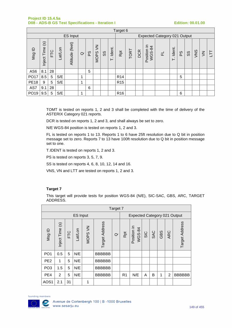
Project ID 15.4.5a D08 - ADS-B GS Test Specifications - Iteration I Edition: 00.01.00
149 of 455
Target 6 ES Input Expected Category 021 Output
Msg
ID
Inje
ct T
ime
(s)
FTC
Lat/L
on
Altit
ude
(feet
)
Q
PS
MO
PS V
N
SS
T. Id
ent.
Rpt
TOR
T
DC
R
Posi
tion
in
WG
S-84
FL
T. Id
ent.
PS
SS
VNS
VN
LTT
AS6 8.1 28 5 PO17 8.5 5 S/E 1 R14 5 PE18 9 5 S/E 1 R15 AS7 9.1 28 6
PO19 9.5 5 S/E 1 R16 6
TOMT is tested on reports 1, 2 and 3 shall be completed with the time of delivery of the ASTERIX Category 021 reports.
DCR is tested on reports 1, 2 and 3, and shall always be set to zero.
N/E WGS-84 position is tested on reports 1, 2 and 3.
FL is tested on reports 1 to 13. Reports 1 to 6 have 25ft resolution due to Q bit in position message set to zero. Reports 7 to 13 have 100ft resolution due to Q bit in position message set to one.
T.IDENT is tested on reports 1, 2 and 3.
PS is tested on reports 3, 5, 7, 9.
SS is tested on reports 4, 6, 8, 10, 12, 14 and 16.
VNS, VN and LTT are tested on reports 1, 2 and 3.
Target 7
This target will provide tests for position WGS-84 (N/E), SIC-SAC, GBS, ARC, TARGET ADDRESS.
Target 7
ES Input Expected Category 021 Output
Msg
ID
Inje
ct T
ime
(s)
FTC
Lat/L
on
MO
PS V
N
Targ
et A
ddre
ss
Q
Rpt
Posi
tion
in
WG
S-84
SIC
SAC
GBS
ARC
Targ
et A
ddre
ss
PO1 0.5 5 N/E BBBBBB
PE2 1 5 N/E BBBBBB
PO3 1.5 5 N/E BBBBBB
PE4 2 5 N/E BBBBBB R1 N/E A B 1 2 BBBBBB
AOS1 2.1 31 1
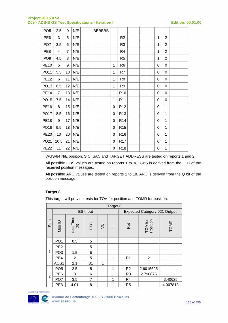
Project ID 15.4.5a D08 - ADS-B GS Test Specifications - Iteration I Edition: 00.01.00
150 of 455
PO5 2.5 0 N/E BBBBBB
PE6 3 5 N/E R2 1 2
PO7 3.5 6 N/E R3 1 2
PE8 4 7 N/E R4 1 2
PO9 4.5 8 N/E R5 1 2
PE10 5 9 N/E 1 R6 0 0
PO11 5.5 10 N/E 1 R7 0 0
PE12 6 11 N/E 1 R8 0 0
PO13 6.5 12 N/E 1 R9 0 0
PE14 7 13 N/E 1 R10 0 0
PO15 7.5 14 N/E 1 R11 0 0
PE16 8 15 N/E 0 R12 0 1
PO17 8.5 16 N/E 0 R13 0 1
PE18 9 17 N/E 0 R14 0 1
PO19 9.5 18 N/E 0 R15 0 1
PE20 10 20 N/E 0 R16 0 1
PO21 10.5 21 N/E 0 R17 0 1
PE22 11 22 N/E 0 R18 0 1
WGS-84 N/E position, SIC, SAC and TARGET ADDRESS are tested on reports 1 and 2.
All possible GBS values are tested on reports 1 to 18. GBS is derived from the FTC of the received position messages.
All possible ARC values are tested on reports 1 to 18. ARC is derived from the Q bit of the position message.
Target 8
This target will provide tests for TOA for position and TOMR for position.
Target 8
Step
ES Input Expected Category 021 Output
Msg
ID
Inje
ct T
ime
(s)
FTC
VN
T Rpt
TOA
for
Posi
tion
TOM
R
1
PO1 0.5 5 PE2 1 5 PO3 1.5 5 PE4 2 5 1 R1 2
AOS1 2.1 31 1
2
PO5 2.5 5 1 R2 2.6015625 PE6 3 6 1 R3 2.796875 PO7 3.5 7 1 R4 3.40625 PE8 4.01 8 1 R5 4.007813
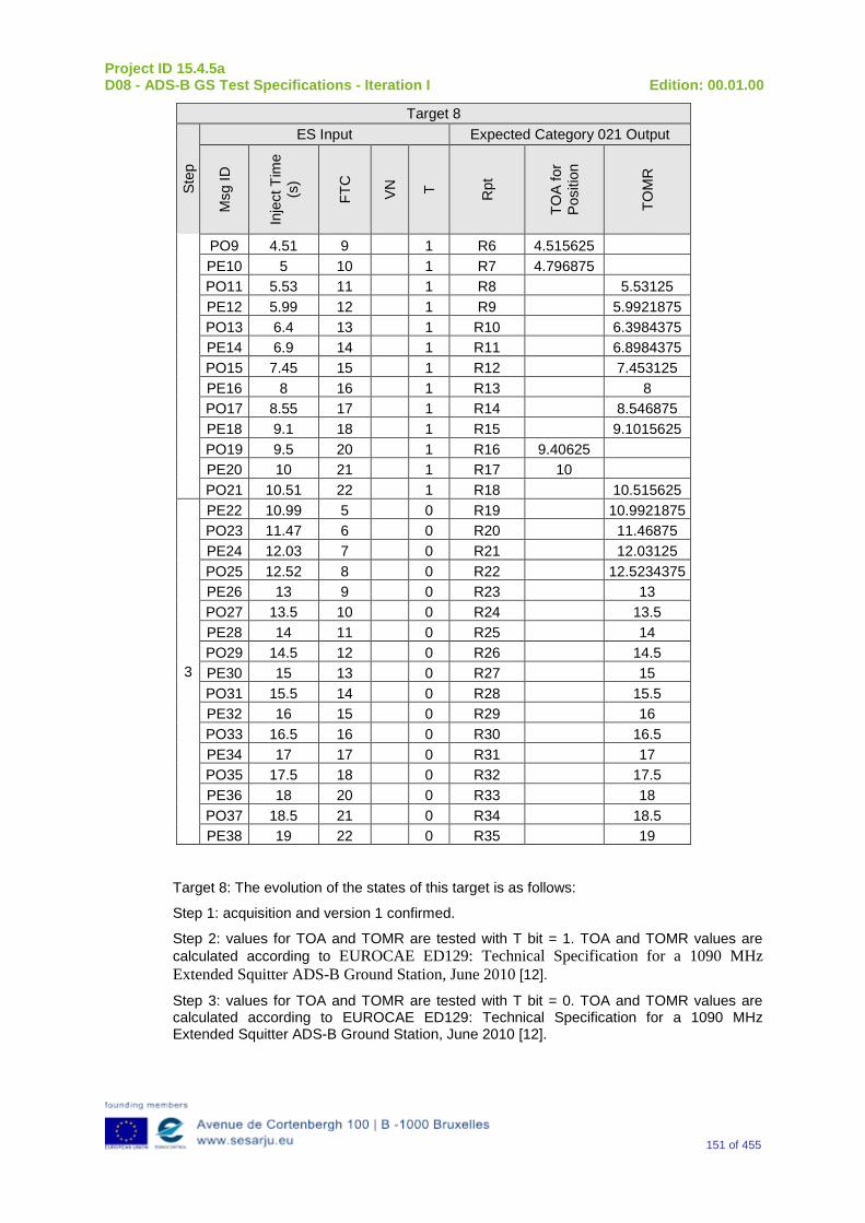
Project ID 15.4.5a D08 - ADS-B GS Test Specifications - Iteration I Edition: 00.01.00
151 of 455
Target 8
Step
ES Input Expected Category 021 Output
Msg
ID
Inje
ct T
ime
(s)
FTC
VN
T Rpt
TOA
for
Posi
tion
TOM
R
PO9 4.51 9 1 R6 4.515625 PE10 5 10 1 R7 4.796875 PO11 5.53 11 1 R8 5.53125 PE12 5.99 12 1 R9 5.9921875 PO13 6.4 13 1 R10 6.3984375 PE14 6.9 14 1 R11 6.8984375 PO15 7.45 15 1 R12 7.453125 PE16 8 16 1 R13 8 PO17 8.55 17 1 R14 8.546875 PE18 9.1 18 1 R15 9.1015625 PO19 9.5 20 1 R16 9.40625 PE20 10 21 1 R17 10 PO21 10.51 22 1 R18 10.515625
3
PE22 10.99 5 0 R19 10.9921875 PO23 11.47 6 0 R20 11.46875 PE24 12.03 7 0 R21 12.03125 PO25 12.52 8 0 R22 12.5234375 PE26 13 9 0 R23 13 PO27 13.5 10 0 R24 13.5 PE28 14 11 0 R25 14 PO29 14.5 12 0 R26 14.5 PE30 15 13 0 R27 15 PO31 15.5 14 0 R28 15.5 PE32 16 15 0 R29 16 PO33 16.5 16 0 R30 16.5 PE34 17 17 0 R31 17 PO35 17.5 18 0 R32 17.5 PE36 18 20 0 R33 18 PO37 18.5 21 0 R34 18.5 PE38 19 22 0 R35 19
Target 8: The evolution of the states of this target is as follows:
Step 1: acquisition and version 1 confirmed.
Step 2: values for TOA and TOMR are tested with T bit = 1. TOA and TOMR values are calculated according to EUROCAE ED129: Technical Specification for a 1090 MHz Extended Squitter ADS-B Ground Station, June 2010 [12].
Step 3: values for TOA and TOMR are tested with T bit = 0. TOA and TOMR values are calculated according to EUROCAE ED129: Technical Specification for a 1090 MHz Extended Squitter ADS-B Ground Station, June 2010 [12].
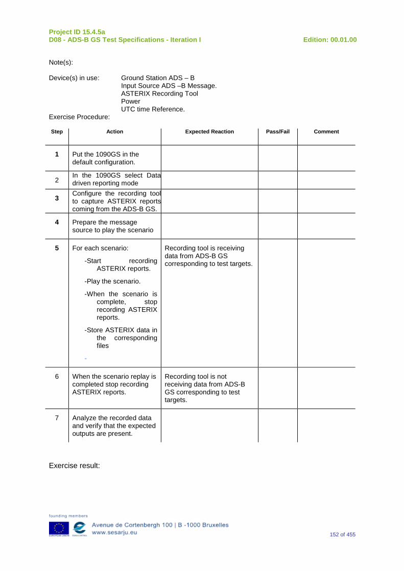
Project ID 15.4.5a D08 - ADS-B GS Test Specifications - Iteration I Edition: 00.01.00
152 of 455
Note(s): Device(s) in use: Ground Station ADS – B
Input Source ADS –B Message. ASTERIX Recording Tool Power UTC time Reference.
Exercise Procedure: Step Action Expected Reaction Pass/Fail Comment
1 Put the 1090GS in the default configuration.
2 In the 1090GS select Data driven reporting mode
3 Configure the recording tool to capture ASTERIX reports coming from the ADS-B GS.
4 Prepare the message source to play the scenario
5 For each scenario:
-Start recording ASTERIX reports.
-Play the scenario.
-When the scenario is complete, stop recording ASTERIX reports.
-Store ASTERIX data in the corresponding files
-
Recording tool is receiving data from ADS-B GS corresponding to test targets.
6 When the scenario replay is completed stop recording ASTERIX reports.
Recording tool is not receiving data from ADS-B GS corresponding to test targets.
7 Analyze the recorded data and verify that the expected outputs are present.
Exercise result:
Project ID 15.4.5a D08 - ADS-B GS Test Specifications - Iteration I Edition: 00.01.00
153 of 455
Pass Fail Done By (Name, Organisation)
Configuration(s) during the exercise Date
Table 9: Verification Exercise Result
G.1.12 Verification SUT requirements N/A
G.1.13 Exercise Tool, Verification Technique and/or Platform
The Exercise will be verified in a platform with the following foreseen tools/equipment:
-Ground Station ADS – B
-RF Source for Fruit and ADS –B Message
-ASTERIX Recording Tool
-Power
-UTC time Reference
The Item reported above will be capable to perform the functionalities reported below.
Ground Station ADS - B
The primary function of the 1090 GS is to receive 1090 MHz Mode S Extended Squitter messages, extract the data contained therein, and create appropriated ASTERIX Category 21 and 23 Reports.
RF Source of Desired Messages
The RF Source of Desired Messages will be capable to generate the Desired1090 MHz messages in accordance with the Standard DO 260 – DO 260A – DO 260B.
UTC Time Reference
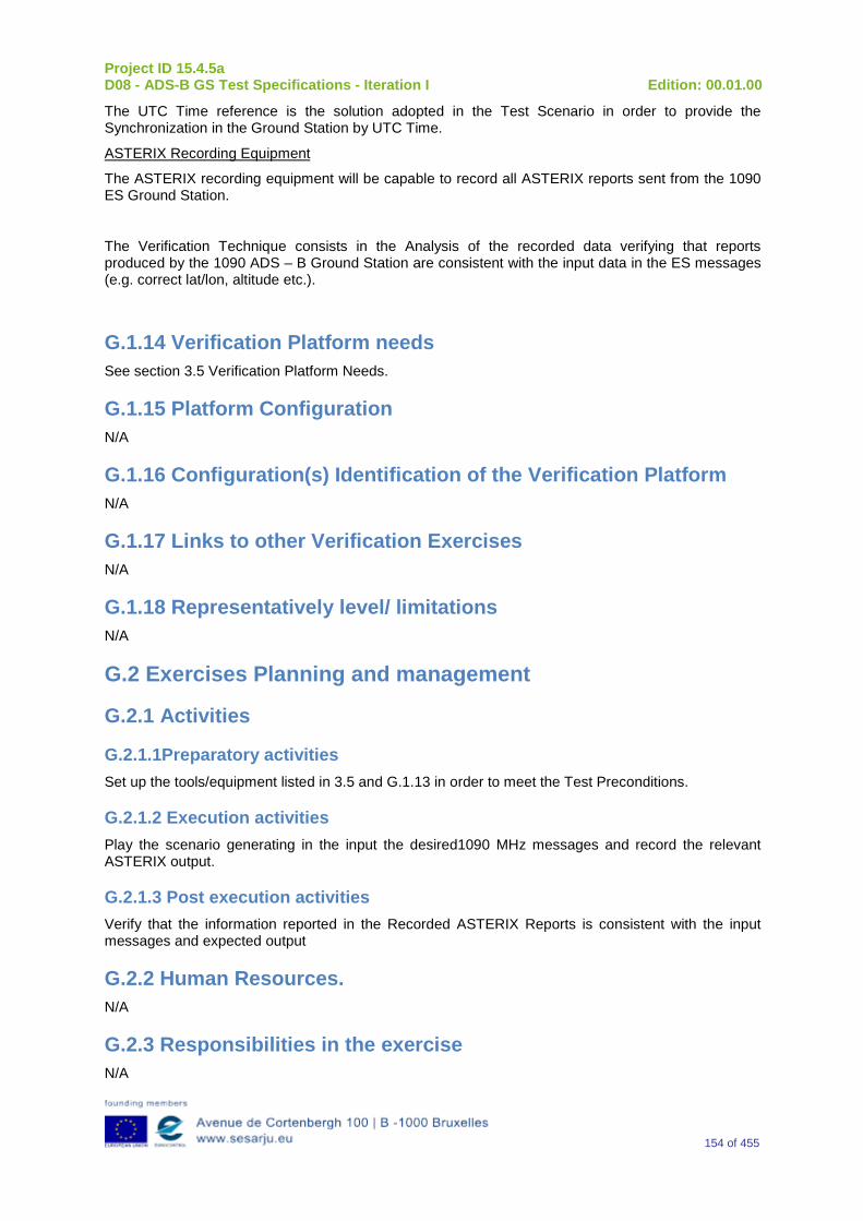
Project ID 15.4.5a D08 - ADS-B GS Test Specifications - Iteration I Edition: 00.01.00
154 of 455
The UTC Time reference is the solution adopted in the Test Scenario in order to provide the Synchronization in the Ground Station by UTC Time.
ASTERIX Recording Equipment
The ASTERIX recording equipment will be capable to record all ASTERIX reports sent from the 1090 ES Ground Station.
The Verification Technique consists in the Analysis of the recorded data verifying that reports produced by the 1090 ADS – B Ground Station are consistent with the input data in the ES messages (e.g. correct lat/lon, altitude etc.).
G.1.14 Verification Platform needs See section 3.5 Verification Platform Needs.
G.1.15 Platform Configuration N/A
G.1.16 Configuration(s) Identification of the Verification Platform N/A
G.1.17 Links to other Verification Exercises N/A
G.1.18 Representatively level/ limitations N/A
G.2 Exercises Planning and management
G.2.1 Activities
G.2.1.1Preparatory activities Set up the tools/equipment listed in 3.5 and G.1.13 in order to meet the Test Preconditions.
G.2.1.2 Execution activities Play the scenario generating in the input the desired1090 MHz messages and record the relevant ASTERIX output.
G.2.1.3 Post execution activities Verify that the information reported in the Recorded ASTERIX Reports is consistent with the input messages and expected output
G.2.2 Human Resources. N/A
G.2.3 Responsibilities in the exercise N/A
Project ID 15.4.5a D08 - ADS-B GS Test Specifications - Iteration I Edition: 00.01.00
155 of 455
G.2.4 Training N/A
G.2.5 Time planning N/A
G.2.6 Risks. N/A
G.2.7 Errors and Observation handling N/A
G.3 Analysis Specification
G.3.1 Data collection methods The data’s collection during the test will be Qualitative. In fact after test execution the analysis of ASTERIX data will be performed verifying that the values reported in output are in line with the values generated in input.
G.3.2 Analysis method N/A
G.3.3 Data logging requirements The data logging requirements for this scenario will foresee at least ASTERIX CAT 21 and ASTERIX CAT 23 item.
Project ID 15.4.5a D08 - ADS-B GS Test Specifications - Iteration I Edition: 00.01.00
156 of 455
Appendix H Verification Exercise EXE-15.04.05.a-TS.0020.0000-GS Integrity
H.1Exercise Scope and Justification
H.1.1 Exercise Level The level of the exercise is functional.
H.1.2 Exercise Type The type of this exercise is Test
H.1.3 Description of the system being addressed; Ground Station ADS – B.
H.1.4 Context of the verification exercise This document is applied to FAT (Factory Acceptance Test).
H.1.5 Required Datasets 1090MHz Extended Squitter Messages input and 1090GS ASTERIX output , containing at least 500,000 ADS – B messages.
H.1.6 Verification objectives Verify that the decoder undetected message error rate is better than 1 in 105 messages.
OBJ-15.04.05.a-TS.0020.0001 The aim of this objective is to check that the likelihood of an ADS-B Ground Domain system integrity failure is 2E-05 or less per hour.
H.1.7Inputs At least 500,000 ADS – B messages.
H.1.8 Outputs Recorded Data.
H.1.9 Entrance criteria Start the generation of 500,000 ADS – B messages.
H.1.10 Exit Criteria The Test will finish after the generation of all messages foreseen in the input.
H.1.11 Exercise procedure Exercise ID/Title: EXE-15.4.5.a-TS.0020.0000 / Integrity
Pass Criteria: The test is passed if it is possible to verify that the 1090 GS integrity match the following condition: the decoder undetected message error rate shall be
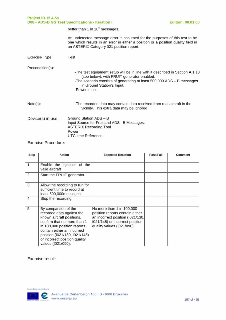
Project ID 15.4.5a D08 - ADS-B GS Test Specifications - Iteration I Edition: 00.01.00
157 of 455
better than 1 in 105 messages. An undetected message error is assumed for the purposes of this test to be one which results in an error in either a position or a position quality field in an ASTERIX Category 021 position report.
Exercise Type: Test
Precondition(s): -The test equipment setup will be in line with it described in Section A.1.13
(see below), with FRUIT generator enabled. -The scenario consists of generating at least 500,000 ADS – B messages
in Ground Station’s Input. -Power is on.
Note(s): -The recorded data may contain data received from real aircraft in the vicinity. This extra data may be ignored.
Device(s) in use: Ground Station ADS – B Input Source for Fruit and ADS –B Messages. ASTERIX Recording Tool Power UTC time Reference.
Exercise Procedure:
Step Action Expected Reaction Pass/Fail Comment
1 Enable the injection of the valid aircraft
2 Start the FRUIT generator.
3 Allow the recording to run for sufficient time to record at least 500,000messages.
4 Stop the recording.
5 By comparison of the recorded data against the known aircraft positions, confirm that no more than 1 in 100,000 position reports contain either an incorrect position (I021/130, I021/145) or incorrect position quality values (I021/090).
No more than 1 in 100,000 position reports contain either an incorrect position (I021/130, I021/145) or incorrect position quality values (I021/090).
Exercise result:
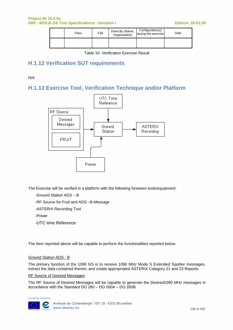
Project ID 15.4.5a D08 - ADS-B GS Test Specifications - Iteration I Edition: 00.01.00
158 of 455
Pass Fail Done By (Name, Organisation)
Configuration(s) during the exercise Date
Table 10: Verification Exercise Result
H.1.12 Verification SUT requirements
N/A
H.1.13 Exercise Tool, Verification Technique and/or Platform
The Exercise will be verified in a platform with the following foreseen tools/equipment:
-Ground Station ADS – B
-RF Source for Fruit and ADS –B Message
-ASTERIX Recording Tool
-Power
-UTC time Reference
The Item reported above will be capable to perform the functionalities reported below.
Ground Station ADS - B
The primary function of the 1090 GS is to receive 1090 MHz Mode S Extended Squitter messages, extract the data contained therein, and create appropriated ASTERIX Category 21 and 23 Reports.
RF Source of Desired Messages
The RF Source of Desired Messages will be capable to generate the Desired1090 MHz messages in accordance with the Standard DO 260 – DO 260A – DO 260B.
Project ID 15.4.5a D08 - ADS-B GS Test Specifications - Iteration I Edition: 00.01.00
159 of 455
RF Source of FRUIT
The RF Source of FRUIT will be capable of producing Mode A/C, Mode S short and Mode S long messages randomly distributed in time.
UTC Time Reference
The UTC Time reference is the solution adopted in the Test Scenario in order to provide the Synchronization in the Ground Station by UTC Time.
ASTERIX Recording Equipment
The ASTERIX recording equipment will be capable to record all ASTERIX reports sent from the 1090 ES Ground Station.
The Verification Technique consists in the comparison of the recorded data against the known aircraft positions, confirming that no more than 1 in 100,000 position reports contains either an incorrect position (I021/130, I021/145) or an incorrect position quality values (I021/090).
H.1.14 Verification Platform needs See section 3.5 Verification Platform Needs.
H.1.15 Platform Configuration N/A
H.1.16 Configuration(s) Identification of the Verification Platform N/A
H.1.17 Links to other Verification Exercises N/A
H.1.18 Representatively level/ limitations N/A
H.2 Exercises Planning and management
H.2.1 Activities N/A
H.2.1.1 Preparatory activities Set up the tools/equipment listed in 3.5 and H.1.13 in order to meet the Test Preconditions.
H.2.1.2 Execution activities Play the scenario generating in the input the desired 1090 MHz messages and record the relevant ASTERIX output.
H.2.1.3 Post execution activities Verify that the information reported in the recorded ASTERIX Report is consistent with the input messages. In fact by means of comparison of the recorded data against the known aircraft positions it should be possible to confirm that no more than 1 in 100,000 position reports contain either an incorrect position (I021/130, I021/145) or an incorrect position quality values (I021/090).
Project ID 15.4.5a D08 - ADS-B GS Test Specifications - Iteration I Edition: 00.01.00
160 of 455
H.2.2 Human Resources. N/A
H.2.3 Responsibilities in the exercise N/A
H.2.4 Training N/A
H.2.5 Time planning N/A
H.2.6 Risks. N/A
H.2.7 Errors and Observation handling N/A
H.3 Analysis Specification
H.3.1 Data collection methods The data collection during the test will be Qualitative. In fact after the test execution, the analysis of ASTERIX Data will be performed verifying that the values reported in the output are in line with the values generated in input.
H.3.2 Analysis method N/A
H.3.3 Data logging requirements The data logging requirements for this scenario will foresee at least ASTERIX CAT 21 and ASTERIX CAT 23 item.
Project ID 15.4.5a D08 - ADS-B GS Test Specifications - Iteration I Edition: 00.01.00
161 of 455
Appendix I Verification Exercise EXE-15.04.05.a-TS.0020.0010-GS Continuity
I.1Exercise Scope and Justification
I.1.1 Exercise Level The level of the exercise is functional.
I.1.2 Exercise Type The type of this exercise is Analysis
I.1.3 Description of the system being addressed; ADS–B Ground Station.
I.1.4 Context of the verification exercise This document is applied to FAT (Factory Acceptance Test).
I.1.5 Required Datasets MTBF: Mean Time Between Failure
MTTR: Mean Time To Repair
I.1.6 Verification objectives Demonstrate by analysis that the probability of a 1090 ES Ground Station continuity failure meets the requirements of 1E-05 or less per hour.
OBJ-15.04.05.a-TS.0020.0002 The aim of this objective is to check that the likelihood of a “Ground ADS-B Receive” function continuity failure is 1E-05 or less per hour.
I.1.7Inputs Design documentation.
I.1.8 Outputs Availability is quantified as the ratio of the time the system is actually available to the time the system is planned to be available.
I.1.9 Entrance criteria N/A
I.1.10 Exit Criteria N/A
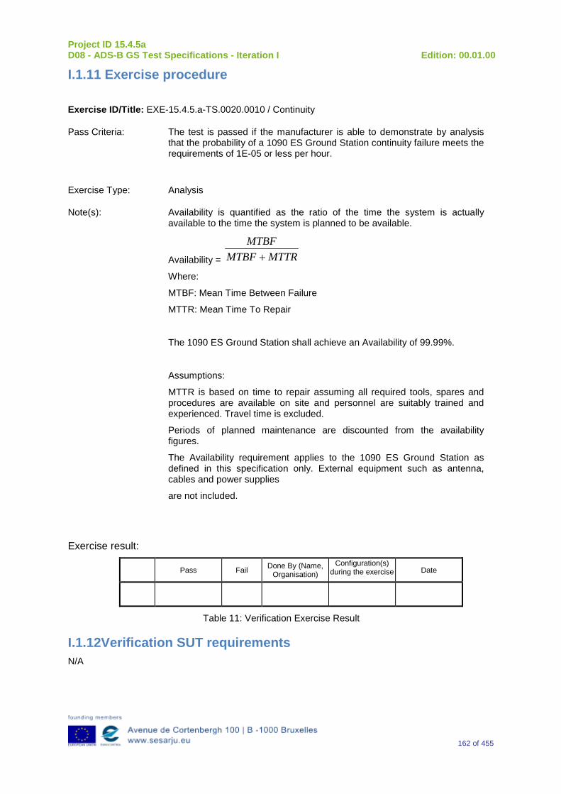
Project ID 15.4.5a D08 - ADS-B GS Test Specifications - Iteration I Edition: 00.01.00
162 of 455
I.1.11 Exercise procedure
Exercise ID/Title: EXE-15.4.5.a-TS.0020.0010 / Continuity
Pass Criteria: The test is passed if the manufacturer is able to demonstrate by analysis that the probability of a 1090 ES Ground Station continuity failure meets the requirements of 1E-05 or less per hour.
Exercise Type: Analysis
Note(s): Availability is quantified as the ratio of the time the system is actually available to the time the system is planned to be available.
Availability = MTTRMTBFMTBF
+
Where:
MTBF: Mean Time Between Failure
MTTR: Mean Time To Repair
The 1090 ES Ground Station shall achieve an Availability of 99.99%.
Assumptions:
MTTR is based on time to repair assuming all required tools, spares and procedures are available on site and personnel are suitably trained and experienced. Travel time is excluded.
Periods of planned maintenance are discounted from the availability figures.
The Availability requirement applies to the 1090 ES Ground Station as defined in this specification only. External equipment such as antenna, cables and power supplies
are not included.
Exercise result:
Pass Fail Done By (Name, Organisation)
Configuration(s) during the exercise Date
Table 11: Verification Exercise Result
I.1.12Verification SUT requirements N/A
Project ID 15.4.5a D08 - ADS-B GS Test Specifications - Iteration I Edition: 00.01.00
163 of 455
I.1.13 Exercise Tool, Verification Technique and/or Platform N/A
I.1.14 Verification Platform needs See section 3.5 Verification Platform Needs.
I.1.15 Platform Configuration N/A
I.1.16 Configuration(s) Identification of the Verification Platform N/A
I.1.17 Links to other Verification Exercises N/A
I.1.18 Representatively level/ limitations N/A
I.2 Exercises Planning and management
I.2.1 Activities N/A
I.2.1.1 Preparatory activities N/A
I.2.1.2 Execution activities N/A
I.2.1.3 Post execution activities N/A
I.2.2 Human Resources. N/A
I.2.3 Responsibilities in the exercise N/A
I.2.4 Training N/A
I.2.5 Time planning N/A
Project ID 15.4.5a D08 - ADS-B GS Test Specifications - Iteration I Edition: 00.01.00
164 of 455
I.2.6Risks. N/A
I.2.7 Errors and Observation handling N/A
I.3 Analysis Specification
I.3.1 Data collection methods N/A
I.3.2Analysis method In the 15.4.5b project the Analysis Method will be defined according to the Internal Industry Procedures.
I.3.3Data logging requirements Availability value.
Project ID 15.4.5a D08 - ADS-B GS Test Specifications - Iteration I Edition: 00.01.00
165 of 455
Appendix JVerification Exercise EXE-15.04.05.a-TS.0020.0020-GS Latency
J.1Exercise Scope and Justification
J.1.1 Exercise Level The level of the exercise is functional.
J.1.2 Exercise Type The type of this exercise is Test.
J.1.3 Description of the system being addressed; ADS – B Ground Station.
J.1.4 Context of the verification exercise This document is applied to FAT (Factory Acceptance Test).
J.1.5 Required Datasets 1090MHz Extended Squitter Messages input and 1090GS ASTERIX output.
J.1.6 Verification objectives Verify that the 95% Latency is less than 0.5 seconds.
95 % Latency is determined by calculating the delay between the RF reception of the 1090ES and the delivery of each ASTERIX report for all “n” targets verifying that 95% of latency measurements is less than 0.5 seconds.
OBJ-15.04.05.a-TS.0020.0003 The aim of this objective is to check that the 95% latency for ADS-B surveillance reports (measured between points D and E2 output of the “Ground ADS-B Receive” function) is not greater than 0.5 seconds, excluding communication latency to the ATC processing system. Note: It is assumed that all latency on the “Ground ADS-B Receive” function is compensated.
J.1.7Inputs 1090MHz Extended Squitter Messages in input interface relevant to “n” different Targets.
J.1.8 Outputs Latency measurements.
J.1.9 Entrance criteria Start the generation 1090 MHz Extended Squitter messages relevant to “n” targets.
Project ID 15.4.5a D08 - ADS-B GS Test Specifications - Iteration I Edition: 00.01.00
166 of 455
J.1.10 Exit Criteria The Test will finish after the generation of all messages foreseen in the input.
J.1.11 Exercise procedure Exercise ID/Title: EXE-15.04.05.a-TS.0020.0020 / Latency
Pass Criteria: The test is passed if it is possible to verify that 95% latency for ADS-B surveillance reports at the output of the 1090 GS is no greater than 0.5 seconds, measured from 1090ES message reception to the transmission of the corresponding target report by the 1090 GS.
Exercise Type: Test
Precondition(s): The scenario consists of generating in input at RF interface the messages relevant to “n” different Targets.
All UTC synchronised devices are in the UTC synchronised state.
Note(s): Since the objective of this test is to measure latency through the Ground Station, a method of determining the difference between the time of arrival of the 1090 ES message at the RF input of the Ground Station and the time of transmission of the corresponding ASTERIX report must be devised. The sum of the measurement uncertainty and the measured latency must be less than the maximum latency specified above.
Device(s) in use: Ground Station ADS – B
Input Source for Fruit and ADS –B Message
ASTERIX Recording Tool
Power
UTC time Reference
Exercise Procedure:
Step Action Expected Reaction Pass/Fail Comment
1 Inject the Target message and FRUIT messages into the 1090 ES Ground Station and record the resulting reports.
2 95 % Latency is determined by calculating the latency of each ASTERIX report for all n targets and verifying that 95% of measurements is less than 0.5 seconds.
The sum of the calculated latency and the measurement uncertainty for each report must be less than maximum specified.
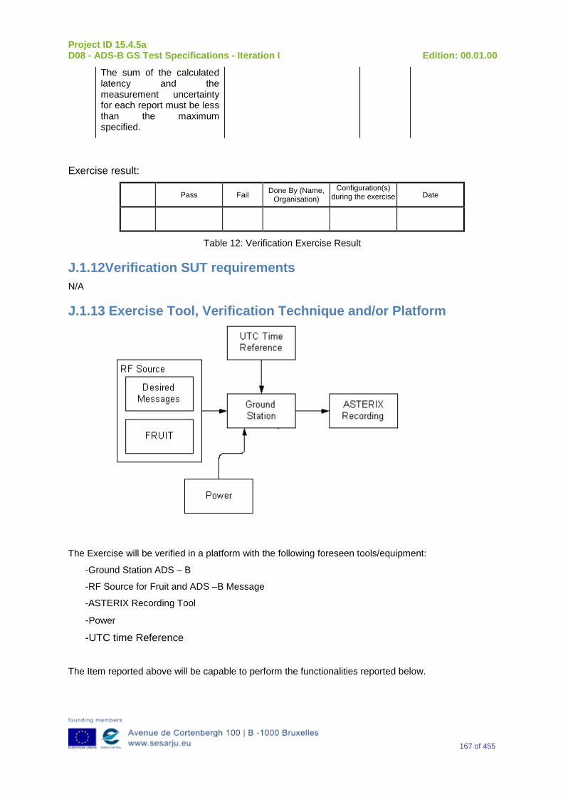
Project ID 15.4.5a D08 - ADS-B GS Test Specifications - Iteration I Edition: 00.01.00
167 of 455
The sum of the calculated latency and the measurement uncertainty for each report must be less than the maximum specified.
Exercise result:
Pass Fail Done By (Name, Organisation)
Configuration(s) during the exercise Date
Table 12: Verification Exercise Result
J.1.12Verification SUT requirements N/A
J.1.13 Exercise Tool, Verification Technique and/or Platform
The Exercise will be verified in a platform with the following foreseen tools/equipment:
-Ground Station ADS – B
-RF Source for Fruit and ADS –B Message
-ASTERIX Recording Tool
-Power
-UTC time Reference
The Item reported above will be capable to perform the functionalities reported below.
Project ID 15.4.5a D08 - ADS-B GS Test Specifications - Iteration I Edition: 00.01.00
168 of 455
Ground Station ADS - B
The primary function of the 1090 GS is to receive 1090 MHz Mode S Extended Squitter messages, extract the data contained therein, and create appropriated ASTERIX Category 21 and 23 Reports.
RF Source of Desired Messages
The RF Source of Desired Messages will be capable to generate the Desired1090 MHz messages in accordance with the Standard DO 260 – DO 260A – DO 260B.
RF Source of FRUIT
The RF Source of FRUIT will be capable of producing Mode A/C, Mode S short and Mode S long messages randomly distributed in time.
UTC Time Reference
The UTC Time reference is the solution adopted in the Test Scenario in order to provide the Synchronization in the Ground Station by UTC Time.
ASTERIX Recording Equipment
The ASTERIX recording equipment will be capable to record all ASTERIX reports sent from the 1090 ES Ground Station.
The Verification Technique consists in the verification of 95 % Latency calculating the latency of each ASTERIX report for all n targets generated in the input verifying that 95% of measurements are less than 0.5 seconds.
J.1.14 Verification Platform needs See section 3.5 Verification Platform Needs.
J.1.15 Platform Configuration N/A
J.1.16 Configuration(s) Identification of the Verification Platform N/A
J.1.17 Links to other Verification Exercises N/A
J.1.18 Representatively level/ limitations N/A
J.2 Exercises Planning and management
J.2.1 Activities
J.2.1.1Preparatory activities Setup the tools/equipment listed in 3.5 and J.1.13 in order to meet the Test Preconditions
J.2.1.2 Execution activities Play the scenario generating in the input the Desired1090 MHz messages and record the relevant ASTERIX output.
Project ID 15.4.5a D08 - ADS-B GS Test Specifications - Iteration I Edition: 00.01.00
169 of 455
J.2.1.3 Post execution activities The post execution activities in order to verify the 95 % Latency consists in the calculation of the latency for each ASTERIX report for all n targets generated in input verifying that 95% of measurements are less than 0.5 seconds.
J.2.2 Human Resources. N/A
J.2.3 Responsibilities in the exercise N/A
J.2.4 Training N/A
J.2.5 Time planning N/A
J.2.6 Risks. N/A
J.2.7 Errors and Observation handling N/A
J.3 Analysis Specification
J.3.1 Data collection methods The data’s collection during the test will be Qualitative. In fact after the test execution the analysis of recorded ASTERIX Data will be performed measuring the ASTERIX report latency for all n targets generated in input and verifying that 95% of measurements are less than 0.5 seconds.
J.3.2 Analysis method N/A
J.3.3 Data logging requirements
The data logging requirements for this scenario will foresee at least ASTERIX CAT 21 and ASTERIX CAT 23 item.
Project ID 15.4.5a D08 - ADS-B GS Test Specifications - Iteration I Edition: 00.01.00
170 of 455
Appendix K Verification Exercise EXE-15.04.05.a-TS.0020.0030-GS TOA Accuracy
K.1Exercise Scope and Justification
K.1.1 Exercise Level The level of the exercise is functional.
K.1.2 Exercise Type The type of this exercise is Analysis
K.1.3 Description of the system being addressed; Ground Station ADS–B.
K.1.4 Context of the verification exercise This document is applied to FAT (Factory Acceptance Test).
K.1.5 Required Datasets System Documentation like, for instance, datasheet or system design/choose in order to demonstrate that the Ground Station ADS – B can achieve the Verification objective reported in next section.
K.1.6 Verification objectives Verify by analysis that the time of applicability conveyed in the 1090 GS reports has an absolute accuracy relative to UTC of ±0.1 seconds or less.
OBJ-15.04.05.a-TS.0020.0004 The aim of this objective is to check that the time of applicability conveyed in the ADS-B surveillance report haves an absolute accuracy relative to UTC of ±0.1 seconds or less.
K.1.7Inputs System Documentation like, for instance, datasheet or system design/choose in order to demonstrate that the Ground Station ADS – B can achieve the Verification objective.
K.1.8Outputs TOA accuracy test documentation
K.1.9 Entrance criteria N/A
K.1.10 Exit Criteria N/A
Project ID 15.4.5a D08 - ADS-B GS Test Specifications - Iteration I Edition: 00.01.00
171 of 455
K.1.11 Exercise procedure Exercise ID/Title: EXE-15.4.5.a-TS. 0020.0030 / TOA Accuracy
Pass Criteria: The test is passed if the manufacturer is able to demonstrate by analysis that the time of applicability conveyed in the 1090 GS reports has an absolute accuracy relative to UTC of ±0.1 seconds or less.
Exercise Type: Analysis
Exercise result:
Pass Fail Done By (Name, Organisation)
Configuration(s) during the exercise Date
Table 13: Verification Exercise Result
K.1.12 Verification SUT requirements N/A
K.1.13 Exercise Tool, Verification Technique and/or Platform N/A
K.1.14 Verification Platform needs See section 3.5 Verification Platform Needs.
K.1.15 Platform Configuration N/A
K.1.16 Configuration(s) Identification of the Verification Platform N/A
K.1.17 Links to other Verification Exercises N/A
K.1.18 Representatively level/ limitations N/A
Project ID 15.4.5a D08 - ADS-B GS Test Specifications - Iteration I Edition: 00.01.00
172 of 455
K.2 Exercises Planning and management
K.2.1 Activities
K.2.1.1Preparatory activities N/A
K.2.1.2 Execution activities N/A
K.2.1.3 Post execution activities N/A
K.2.2 Human Resources. N/A
K.2.3 Responsibilities in the exercise N/A
K.2.4 Training N/A
K.2.5 Time planning N/A
K.2.6 Risks. N/A
K.2.7 Errors and Observation handling N/A
K.3 Analysis Specification
K.3.1 Data collection methods N/A
K.3.2 Analysis method N/A
K.3.3 Data logging requirements N/A
Project ID 15.4.5a D08 - ADS-B GS Test Specifications - Iteration I Edition: 00.01.00
173 of 455
Appendix L Verification Exercise EXE-15.04.05.a-TS.0020.0040-GS Capacity
L.1Exercise Scope and Justification
L.1.1 Exercise Level The level of the exercise is functional.
L.1.2 Exercise Type The type of this exercise is Test
L.1.3 Description of the system being addressed; ADS – B Ground Station.
L.1.4Context of the verification exercise This document is applied to FAT (Factory Acceptance Test).
L.1.5 Required Datasets 1090MHz Extended Squitter Messages input and 1090GS ASTERIX output.
L.1.6 Verification objectives Verify the overall system capacity in a scenario that foresees a maximum Ground Station’s load in accordance to RAD Scenario.
OBJ-15.04.05.a-TS.0020.0007 The aim of this objective is to check that the ADS-B Ground Domain has capacity to handle the reports from the maximum load of aircraft in the environment as described in the OSED without degradation.
L.1.7Inputs A number of targets in order to simulate the maximum Ground Station’s load in accordance to RAD Scenario.
L.1.8 Outputs ASTERIX Report Recording.
L.1.9 Entrance criteria Start the generation 1090 MHz Extended Squitter messages relevant to maximum Ground Station’s load in accordance to RAD Scenario.
L.1.10 Exit Criteria The Test will finish after the generation of all messages foreseen in input and once all outputs have been recorded and analyzed.
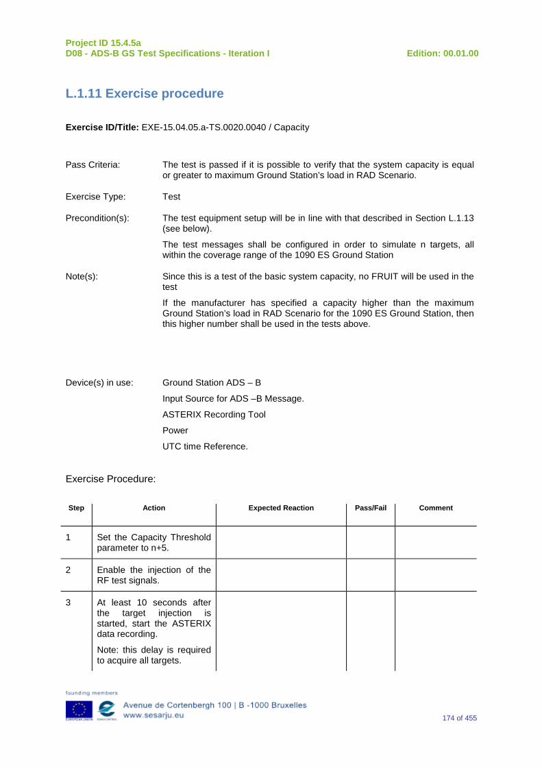
Project ID 15.4.5a D08 - ADS-B GS Test Specifications - Iteration I Edition: 00.01.00
174 of 455
L.1.11 Exercise procedure
Exercise ID/Title: EXE-15.04.05.a-TS.0020.0040 / Capacity
Pass Criteria: The test is passed if it is possible to verify that the system capacity is equal or greater to maximum Ground Station’s load in RAD Scenario.
Exercise Type: Test
Precondition(s): The test equipment setup will be in line with that described in Section L.1.13 (see below).
The test messages shall be configured in order to simulate n targets, all within the coverage range of the 1090 ES Ground Station
Note(s): Since this is a test of the basic system capacity, no FRUIT will be used in the test
If the manufacturer has specified a capacity higher than the maximum Ground Station’s load in RAD Scenario for the 1090 ES Ground Station, then this higher number shall be used in the tests above.
Device(s) in use: Ground Station ADS – B
Input Source for ADS –B Message.
ASTERIX Recording Tool
Power
UTC time Reference.
Exercise Procedure:
Step Action Expected Reaction Pass/Fail Comment
1 Set the Capacity Threshold parameter to n+5.
2 Enable the injection of the RF test signals.
3 At least 10 seconds after the target injection is started, start the ASTERIX data recording.
Note: this delay is required to acquire all targets.
Project ID 15.4.5a D08 - ADS-B GS Test Specifications - Iteration I Edition: 00.01.00
175 of 455
4 Confirm from the SNMP client that no target capacity overload is reported.
5 Allow the recording to run for at least two minutes, then stop the recording and signal injection.
6 From the recorded data, confirm that the average number of ASTERIX Category 021 target reports output by the Ground Station for each target is 4 ± 1% per second for the duration of the recording.
7 Confirm also that the recorded ASTERIX Category 023 messages do not have the ODP bit set (in item I023/100).
Exercise result:
Pass Fail Done By (Name, Organisation)
Configuration(s) during the exercise Date
Table 14: Verification Exercise Result
L.1.12 Verification SUT requirements N/A
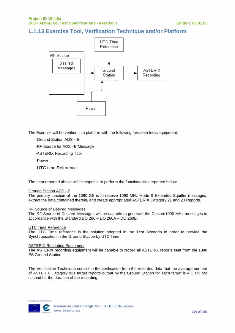
Project ID 15.4.5a D08 - ADS-B GS Test Specifications - Iteration I Edition: 00.01.00
176 of 455
L.1.13 Exercise Tool, Verification Technique and/or Platform
The Exercise will be verified in a platform with the following foreseen tools/equipment:
-Ground Station ADS – B
-RF Source for ADS –B Message
-ASTERIX Recording Tool
-Power -UTC time Reference
The Item reported above will be capable to perform the functionalities reported below. Ground Station ADS - B The primary function of the 1090 GS is to receive 1090 MHz Mode S Extended Squitter messages, extract the data contained therein, and create appropriated ASTERIX Category 21 and 23 Reports. RF Source of Desired Messages The RF Source of Desired Messages will be capable to generate the Desired1090 MHz messages in accordance with the Standard DO 260 – DO 260A – DO 260B. UTC Time Reference The UTC Time reference is the solution adopted in the Test Scenario in order to provide the Synchronization in the Ground Station by UTC Time. ASTERIX Recording Equipment The ASTERIX recording equipment will be capable to record all ASTERIX reports sent from the 1090 ES Ground Station.
The Verification Technique consist in the verification from the recorded data that the average number of ASTERIX Category 021 target reports output by the Ground Station for each target is 4 ± 1% per second for the duration of the recording.
Project ID 15.4.5a D08 - ADS-B GS Test Specifications - Iteration I Edition: 00.01.00
177 of 455
L.1.14 Verification Platform needs See section 3.5 Verification Platform Needs.
L.1.15 Platform Configuration N/A
L.1.16 Configuration(s) Identification of the Verification Platform N/A
L.1.17 Links to other Verification Exercises N/A
L.1.18 Representatively level/ limitations N/A
L.2 Exercises Planning and management
L.2.1 Activities
L.2.1.1 Preparatory activities Setup the tools/equipment listed in 3.5 and A.1.13 in order to meet the Test Preconditions
L.2.1.2 Execution activities Play the scenario generating in the input the Desired1090 MHz messages and record the relevant ASTERIX output.
L.2.1.3 Post execution activities The post execution activities in order to verify the System Capacity consists in the verification from the recorded data that the average number of ASTERIX Category 021 target reports output by the Ground Station for each target is 4 ± 1% per second for the duration of the recording.
L.2.2 Human Resources. N/A
L.2.3 Responsibilities in the exercise N/A
L.2.4 Training N/A
L.2.5 Time planning N/A

Project ID 15.4.5a D08 - ADS-B GS Test Specifications - Iteration I Edition: 00.01.00
178 of 455
L.2.6 Risks. N/A
L.2.7 Errors and Observation handling N/A
L.3 Analysis Specification
L.3.1 Data collection methods The data’s collection during the test will be Qualitative.
L.3.2 Analysis method N/A
L.3.3 Data logging requirements The data logging requirements for this scenario will foresee at least ASTERIX CAT 21 and ASTERIX CAT 23 item.
Project ID 15.4.5a D08 - ADS-B GS Test Specifications - Iteration I Edition: 00.01.00
179 of 455
Appendix M Verification Exercise EXE-15.04.05.a-TS.0020.0050-GS Duplicated 24Bit addresses
M.1Exercise Scope and Justification
M.1.1 Exercise Level The level of the exercise is functional.
M.1.2 Exercise Type The type of this exercise is Test
M.1.3 Description of the system being addressed; ADS – B Ground Station.
M.1.4 Context of the verification exercise This document is applied to FAT (Factory Acceptance Test).
M.1.5 Required Datasets 1090MHz Extended Squitter Messages input and 1090GS ASTERIX output.
M.1.6 Verification objectives Verify that the 1090 ES Ground Station is able to produce separate ASTERIX Category 021 reports for two targets with the same Mode S address in accordance with the requirements specified in EUROCAE ED129: Technical Specification for a 1090 MHz Extended Squitter ADS-B Ground Station, June 2010 [12] Section 3.10.1.3.
OBJ-15.04.05.a-TS.0020.0013 The aim of this objective is to check that the probability that the ADS-B Ground Domain detects duplicate ADS-B Aircraft Identities (i.e., discrete Mode A or aircraft identification) within the same sector), and provides an indication of such to the existing ATC Processing System is at least 99%. Notes: 1. Alternatively, the requirement might be fulfilled by the existing ATC Processing System, i.e., beyond interface F2*. 2. This requirement, taken together with ASSUMP 39, will ensure that the appropriate safety objectives are met.
M.1.7 Inputs 1090MHz Extended Squitter Messages in input interface relevant to different Targets (some of them with same 24 Bit Addresses.
M.1.8 Outputs ASTERIX Report Recording.
Project ID 15.4.5a D08 - ADS-B GS Test Specifications - Iteration I Edition: 00.01.00
180 of 455
M.1.9 Entrance criteria Start the generation 1090 MHz Extended Squitter messages relevant to duplicated 24 Bit Addresses.
M.1.10 Exit Criteria The Test will finish after the generation of all messages foreseen in the input and once all outputs have been recorded and analyzed.
M.1.11 Exercise procedure
Exercise ID/Title: EXE-15.04.05.a-TS.0020.0050 / Duplicated 24Bit addresses
Pass Criteria: The test is passed if it is possible to verify that the system is able to produce separate ASTERIX Category 021 reports for two targets with the same Mode S address.
Exercise Type:
Test
Preconditions The test equipment setup will be in line with that described in Section M.1.13 (see below).
In order to test the ability to detect a target with duplicate Mode S address in any point in the lifecycle (i.e. acquisition, maintenance) of the other target three different scenarios are tested. In these scenarios the two targets with the same Mode S address and with 6 - 6.1 NM of horizontal separation are simulated. Altitudes of the targets should be the same. Testing with other altitude combinations is recommended but not required.
Scenario 1
In this scenario the first target is simulated through the acquisition life cycle. When the target passes the range check and CPR validation and enters the maintenance life cycle, ASTERIX Category 021 Output starts to be issued with CL and RC flags of data item I021/040 set to zero. Two more position messages of this target are injected in order to verify that these positions are reported as new updates of the position of this target.
Injection of the second target is then started. After the second target passes the range check and the CPR validation, both targets shall be flagged as duplicates in ASTERIX Category 021 output (ATP is set to one).
The scenario 1 is listed in Table 15.
Note: The later target is the first target with ATP flag of data item I021/040 set to one.
Table 15: Simulating of Two Duplicate Targets in Scenario 1
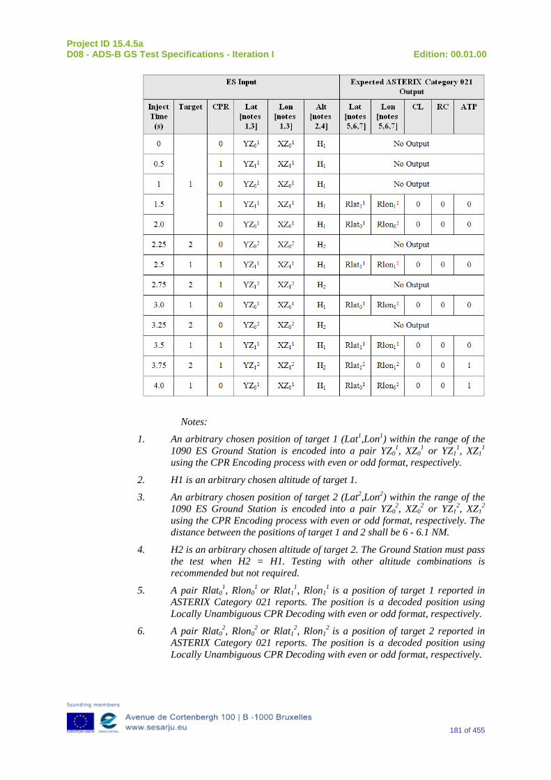
Project ID 15.4.5a D08 - ADS-B GS Test Specifications - Iteration I Edition: 00.01.00
181 of 455
Notes:
1. An arbitrary chosen position of target 1 (Lat1,Lon1) within the range of the 1090 ES Ground Station is encoded into a pair YZ0
1, XZ01 or YZ1
1, XZ11
using the CPR Encoding process with even or odd format, respectively.
2. H1 is an arbitrary chosen altitude of target 1.
3. An arbitrary chosen position of target 2 (Lat2,Lon2) within the range of the 1090 ES Ground Station is encoded into a pair YZ0
2, XZ02 or YZ1
2, XZ12
using the CPR Encoding process with even or odd format, respectively. The distance between the positions of target 1 and 2 shall be 6 - 6.1 NM.
4. H2 is an arbitrary chosen altitude of target 2. The Ground Station must pass the test when H2 = H1. Testing with other altitude combinations is recommended but not required.
5. A pair Rlat01, Rlon0
1 or Rlat1
1, Rlon11 is a position of target 1 reported in
ASTERIX Category 021 reports. The position is a decoded position using Locally Unambiguous CPR Decoding with even or odd format, respectively.
6. A pair Rlat02, Rlon0
2 or Rlat12, Rlon1
2 is a position of target 2 reported in
ASTERIX Category 021 reports. The position is a decoded position using Locally Unambiguous CPR Decoding with even or odd format, respectively.
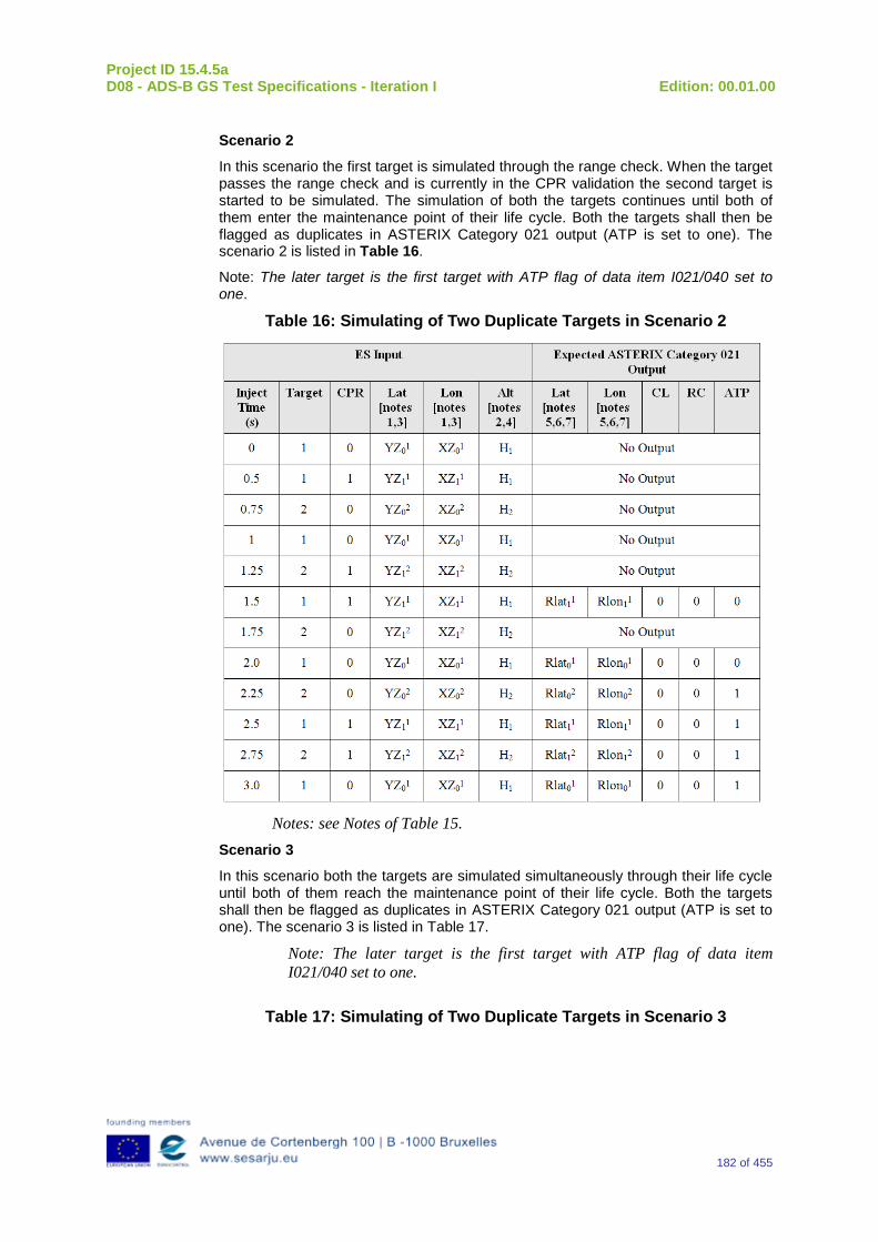
Project ID 15.4.5a D08 - ADS-B GS Test Specifications - Iteration I Edition: 00.01.00
182 of 455
Scenario 2
In this scenario the first target is simulated through the range check. When the target passes the range check and is currently in the CPR validation the second target is started to be simulated. The simulation of both the targets continues until both of them enter the maintenance point of their life cycle. Both the targets shall then be flagged as duplicates in ASTERIX Category 021 output (ATP is set to one). The scenario 2 is listed in Table 16.
Note: The later target is the first target with ATP flag of data item I021/040 set to one.
Table 16: Simulating of Two Duplicate Targets in Scenario 2
Notes: see Notes of Table 15.
Scenario 3
In this scenario both the targets are simulated simultaneously through their life cycle until both of them reach the maintenance point of their life cycle. Both the targets shall then be flagged as duplicates in ASTERIX Category 021 output (ATP is set to one). The scenario 3 is listed in Table 17.
Note: The later target is the first target with ATP flag of data item I021/040 set to one.
Table 17: Simulating of Two Duplicate Targets in Scenario 3
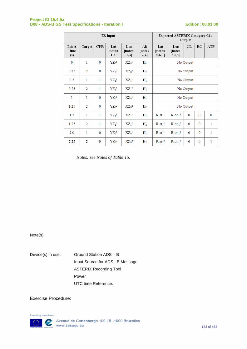
Project ID 15.4.5a D08 - ADS-B GS Test Specifications - Iteration I Edition: 00.01.00
183 of 455
Notes: see Notes of Table 15.
Note(s):
Device(s) in use: Ground Station ADS – B
Input Source for ADS –B Message.
ASTERIX Recording Tool
Power
UTC time Reference.
Exercise Procedure:
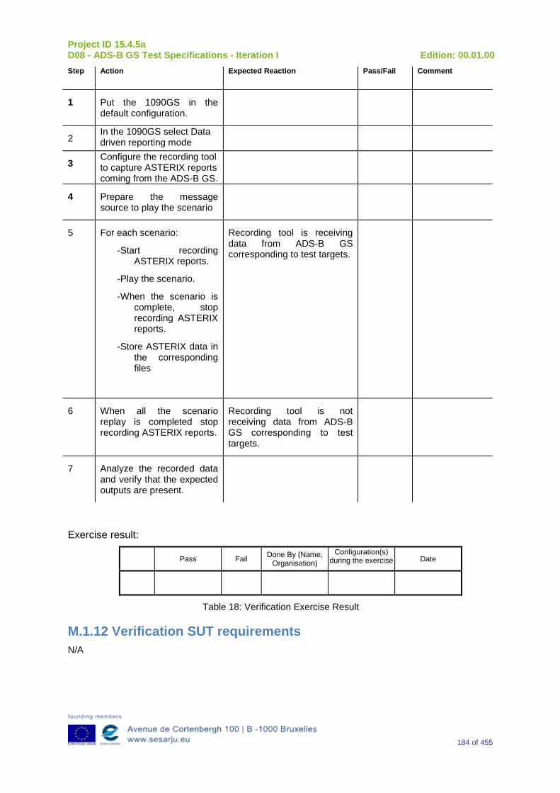
Project ID 15.4.5a D08 - ADS-B GS Test Specifications - Iteration I Edition: 00.01.00
184 of 455
Step Action Expected Reaction Pass/Fail Comment
1 Put the 1090GS in the default configuration.
2 In the 1090GS select Data driven reporting mode
3 Configure the recording tool to capture ASTERIX reports coming from the ADS-B GS.
4 Prepare the message source to play the scenario
5 For each scenario:
-Start recording ASTERIX reports.
-Play the scenario.
-When the scenario is complete, stop recording ASTERIX reports.
-Store ASTERIX data in the corresponding files
Recording tool is receiving data from ADS-B GS corresponding to test targets.
6 When all the scenario replay is completed stop recording ASTERIX reports.
Recording tool is not receiving data from ADS-B GS corresponding to test targets.
7 Analyze the recorded data and verify that the expected outputs are present.
Exercise result:
Pass Fail Done By (Name, Organisation)
Configuration(s) during the exercise Date
Table 18: Verification Exercise Result
M.1.12 Verification SUT requirements N/A
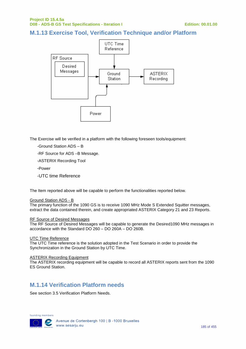
Project ID 15.4.5a D08 - ADS-B GS Test Specifications - Iteration I Edition: 00.01.00
185 of 455
M.1.13 Exercise Tool, Verification Technique and/or Platform
The Exercise will be verified in a platform with the following foreseen tools/equipment:
-Ground Station ADS – B
-RF Source for ADS –B Message.
-ASTERIX Recording Tool
-Power -UTC time Reference
The Item reported above will be capable to perform the functionalities reported below. Ground Station ADS - B The primary function of the 1090 GS is to receive 1090 MHz Mode S Extended Squitter messages, extract the data contained therein, and create appropriated ASTERIX Category 21 and 23 Reports. RF Source of Desired Messages The RF Source of Desired Messages will be capable to generate the Desired1090 MHz messages in accordance with the Standard DO 260 – DO 260A – DO 260B. UTC Time Reference The UTC Time reference is the solution adopted in the Test Scenario in order to provide the Synchronization in the Ground Station by UTC Time. ASTERIX Recording Equipment The ASTERIX recording equipment will be capable to record all ASTERIX reports sent from the 1090 ES Ground Station.
M.1.14 Verification Platform needs See section 3.5 Verification Platform Needs.
Project ID 15.4.5a D08 - ADS-B GS Test Specifications - Iteration I Edition: 00.01.00
186 of 455
M.1.15 Platform Configuration N/A
M.1.16 Configuration(s) Identification of the Verification Platform N/A
M.1.17 Links to other Verification Exercises N/A
M.1.18 Representatively level/ limitations N/A
M.2 Exercises Planning and management
M.2.1 Activities
M.2.1.1 Preparatory activities Setup the tools/equipment listed in 3.5 and M.1.13 in order to meet the Test Preconditions
M.2.1.2 Execution activities Play the scenario generating in the input the desired 1090 MHz messages and record the relevant ASTERIX output.
M.2.1.3 Post execution activities The post execution activities in order to verify the System Capacity consists in the verification from the recorded data that ASTERIX Category 021 target reports output by the Ground Station for each of the targets with duplicated 24 bit Address contains the ATP bit set to 1 once they enter in maintenance mode.
M.2.2 Human Resources. N/A
M.2.3 Responsibilities in the exercise N/A
M.2.4 Training N/A
M.2.5 Time planning N/A
M.2.6 Risks. N/A
Project ID 15.4.5a D08 - ADS-B GS Test Specifications - Iteration I Edition: 00.01.00
187 of 455
M.2.7 Errors and Observation handling N/A
M.3 Analysis Specification
M.3.1 Data collection methods The data’s collection during the test will be Qualitative.
M.3.2 Analysis method N/A
M.3.3 Data logging requirements The data logging requirements for this scenario will foresee at least ASTERIX CAT 21 items.
Project ID 15.4.5a D08 - ADS-B GS Test Specifications - Iteration I Edition: 00.01.00
188 of 455
Appendix N Verification Exercise EXE-15.04.05.a-TS.0020.0060-GS Report Probability for Target in En-Route Airspace
N.1Exercise Scope and Justification
N.1.1 Exercise Level The level of the exercise is functional.
N.1.2 Exercise Type The type of the exercise is Test.
N.1.3 Description of the system being addressed; ADS – B Ground Station.
N.1.4 Context of the verification exercise This document is applied to FAT (Factory acceptance Test).
N.1.5 Required Datasets 1090MHz Extended Squitter Messages input and 1090GS ASTERIX output.
N.1.6 Verification objectives Verify the Requirements related to the enhancement 1090ES Technology, more specifically, the following requirement:
OBJ-15.04.05.a-TS.0020.0017 The aim of this objective is to check that the probability of providing a Surveillance Report containing newly received ADS-B Position data of sufficient quality associated with any aircraft in En Route airspace within 8 seconds is 97%. Notes: 1. Additional requirements are subject to local implementation. Other considerations may apply (see OSA: §C.5.1.5 - “Loss of track information”). 2. Data continuity for a single aircraft is inherently encompassed by this requirement for position update, i.e. in terms of the number of consecutive misses of receiving a position update ultimately leading to a track drop. The required position update probability takes account of normal environmental factors that are experienced during this flight phase, such as coverage variations in received signals (including received satellite signals), that affect the production and receipt of ADS-B positions of sufficient quality on a single aircraft basis. Multiple aircraft data continuity is addressed in ASSUMP 24.
N.1.7Inputs A number of targets in order to simulate the maximum Ground Station’s load in accordance to RAD Scenario.
N.1.8Outputs Recordings of ASTERIX CAT-21 and, optionally, GS system ‘Raw data output’ reports.
Project ID 15.4.5a D08 - ADS-B GS Test Specifications - Iteration I Edition: 00.01.00
189 of 455
N.1.9 Entrance criteria Start the generation of input data.
N.1.10 Exit Criteria Finished recording and performed analysis.
N.1.11 Exercise procedure Exercise ID/Title: EXE-15.04.05.a-TS.0020.0060 / Report Probability for Target in En-Route Airspace Pass Criteria: This test is passed, when the recorded output has data items and
corresponding values as expected.
Exercise Type: Test
Precondition(s): • Test equipment is setup as described above • GS under test is active, and ready for test.
Note(s): N/A
Device(s) in use: SUT is ADS-B GS.
This test procedure verifies that the 1090 ES Ground Station is able to produce a target report containing ADS-B Position data associated with any aircraft in En Route airspace and received from the a/c within the last 8 seconds with a probability of 97%. In order to test the ability to produce a target report, test steps to be done are without FRUIT, with Mode A/C FRUIT overlapping, and with Mode S FRUIT overlapping. Step 1: This test step verifies that the 1090 ES Ground Station is able to produce a target report containing ADS-B Position data associated with any aircraft in En Route airspace and received from the a/c within the last 8 seconds in environment without Mode A/C or Mode S FRUIT with a probability of 97%. Connect the Extended Squitter signal source and set the power level at the receiver input equal to the MTL limit required for the UUT equipment class: –84 dBm for A3 equipment class. The scenario shall be done with 100 a/c (100 different Mode S addresses). ASTERIX output shall be recorded. Compare the output with the known content of the injected input. Any differences that are detected are recorded as an undetected error and that squitter reception is deleted from the count of error free receptions. Additionally compare time of received input with the time when corresponding ASTERIX report was generated. Calculate the measured probability that difference between time of reception and time of output is not greater than 8 seconds in 97% cases. Step 2: This test step verifies that the 1090 ES Ground Station is able to produce a target report containing ADS-B Position data associated with any aircraft in En Route
Project ID 15.4.5a D08 - ADS-B GS Test Specifications - Iteration I Edition: 00.01.00
190 of 455
airspace and received from the a/c within the last 8 seconds in environment with Mode A/C FRUIT with a probability of 97%. Connect the Extended Squitter signal source and set the power level at the receiver input equal to the MTL limit required for the UUT equipment class: –84 dBm for A3 equipment class. Set the power level of three Mode A/C FRUIT sources at the receiver input to the value corresponding to the UUT equipment class: -76, -72 and –68 dBm for A3 equipment class. Activate the Mode A/C FRUIT source so that the FRUIT is pseudo randomly distributed across the Extended Squitter preamble and data block as specified in §2.4.4.4.2.1 of DO-260B. The scenario shall be done with 100 a/c (100 different Mode S addresses). ASTERIX output shall be recorded. Compare the output with the known content of the injected input. Any differences that are detected are recorded as an undetected error and that squitter reception is deleted from the count of error free receptions. Additionally compare time of received input with the time when corresponding ASTERIX report was generated. Calculate the measured probability that difference between time of reception and time of output is not greater than 8 seconds in 97% cases. Step 3: This test step verifies that the 1090 ES Ground Station is able to produce a target report containing ADS-B Position data associated with any aircraft in En Route airspace and received from the a/c within the last 8 seconds in environment with Mode S FRUIT with a probability of 97%. Connect the Extended Squitter signal source and set the power level at the receiver input equal to the MTL limit required for the UUT equipment class plus 12 dB: –72 dBm for A3 equipment class. Set the power level of Mode S FRUIT sources at the receiver input to the value corresponding to the UUT equipment class: -80 dBm for A3 equipment class. Activate the Mode S FRUIT source so that the Mode S FRUIT is pseudo randomly distributed across the data Extended Squitter data block as specified in §2.4.4.4.2.1.2 of DO-260B. The scenario shall be done with 100 a/c (100 different Mode S addresses). ASTERIX output shall be recorded. Compare the output with the known content of the injected input. Any differences that are detected are recorded as an undetected error and that squitter reception is deleted from the count of error free receptions. Additionally compare time of received input with the time when corresponding ASTERIX report was generated. Calculate the measured probability that difference between time of reception and time of output is not greater than 8 seconds in 97% cases.
Exercise Procedure:
Step Action Expected Reaction Pass/Fail Comment
1 Put the GS system under test into the related test configuration.
Project ID 15.4.5a D08 - ADS-B GS Test Specifications - Iteration I Edition: 00.01.00
191 of 455
2 Prepare the test reporting capture tools to capture related GS system ASTERIX CAT-21 and, optional, GS system ‘Raw Data Output’ reports.
3 Prepare the test message source to play the test scenario.
4 Play the test scenario.
5 When the test scenario is complete, stop the recording of ASTERIX CAT-21 and, optional, GS system ‘Raw data output’ reports.
6 Analyze the recorded data:
7 Input test scenario versus ASTERIX CAT-21 reports and
8 Optional, Input test scenario versus GS system ‘Raw data output reports
9 Verify that the GS system under test has generated the expected outputs, and has fulfilled the test objective.
Exercise result:
Pass Fail Done By (Name, Organisation)
Configuration(s) during the exercise Date
Table 19: Verification Exercise Result
N.1.12 Verification SUT requirements N/A
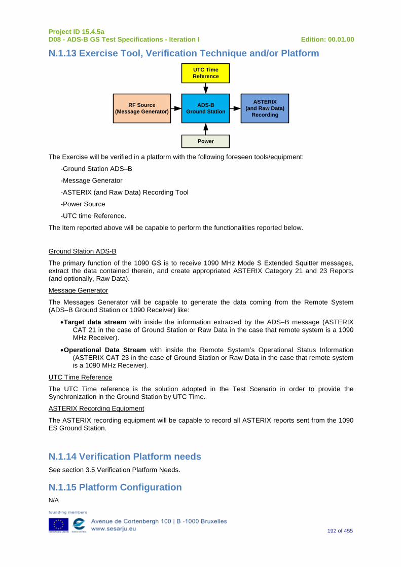
Project ID 15.4.5a D08 - ADS-B GS Test Specifications - Iteration I Edition: 00.01.00
192 of 455
N.1.13 Exercise Tool, Verification Technique and/or Platform
ADS-BGround Station
Power
ASTERIX(and Raw Data)
Recording
UTC Time Reference
RF Source(Message Generator)
The Exercise will be verified in a platform with the following foreseen tools/equipment:
-Ground Station ADS–B
-Message Generator
-ASTERIX (and Raw Data) Recording Tool
-Power Source
-UTC time Reference.
The Item reported above will be capable to perform the functionalities reported below.
Ground Station ADS-B
The primary function of the 1090 GS is to receive 1090 MHz Mode S Extended Squitter messages, extract the data contained therein, and create appropriated ASTERIX Category 21 and 23 Reports (and optionally, Raw Data).
Message Generator
The Messages Generator will be capable to generate the data coming from the Remote System (ADS–B Ground Station or 1090 Receiver) like:
•Target data stream with inside the information extracted by the ADS–B message (ASTERIX CAT 21 in the case of Ground Station or Raw Data in the case that remote system is a 1090 MHz Receiver).
•Operational Data Stream with inside the Remote System’s Operational Status Information (ASTERIX CAT 23 in the case of Ground Station or Raw Data in the case that remote system is a 1090 MHz Receiver).
UTC Time Reference
The UTC Time reference is the solution adopted in the Test Scenario in order to provide the Synchronization in the Ground Station by UTC Time.
ASTERIX Recording Equipment
The ASTERIX recording equipment will be capable to record all ASTERIX reports sent from the 1090 ES Ground Station.
N.1.14 Verification Platform needs See section 3.5 Verification Platform Needs.
N.1.15 Platform Configuration N/A
Project ID 15.4.5a D08 - ADS-B GS Test Specifications - Iteration I Edition: 00.01.00
193 of 455
N.1.16 Configuration(s) Identification of the Verification Platform N/A
N.1.17 Links to other Verification Exercises N/A
N.1.18 Representatively level/ limitations N/A
N.2 Exercises Planning and management
N.2.1 Activities
N.2.1.1 Preparatory activities Setup the tools/equipment listed in 3.5 and N.1.13 in order to meet the Test Preconditions.
N.2.1.2 Execution activities Play the scenario generating in the input the desired messages and record the relevant ASTERIX (and Raw Data) output.
N.2.1.3 Post execution activities The post execution activities will be mainly focused on the analysis of recorded ASTERIX reports (and Raw Data reports). The analysis shall be done in order to verify the right information propagation as requested in each Test Scenario.
N.2.2 Human Resources. N/A
N.2.3 Responsibilities in the exercise N/A
N.2.4 Training N/A
N.2.5 Time planning N/A
N.2.6 Risks. N/A
N.2.7 Errors and Observation handling N/A
Project ID 15.4.5a D08 - ADS-B GS Test Specifications - Iteration I Edition: 00.01.00
194 of 455
N.3 Analysis Specification
N.3.1 Data collection methods The data collection during the test will be Qualitative. In fact after test execution the analysis of ASTERIX Data will be performed verifying that the values reported in the output are in line with the values generated in the input.
N.3.2 Analysis method N/A
N.3.3 Data logging requirements The data logging requirements for this scenario will foresee at least ASTERIX CAT 21 items.
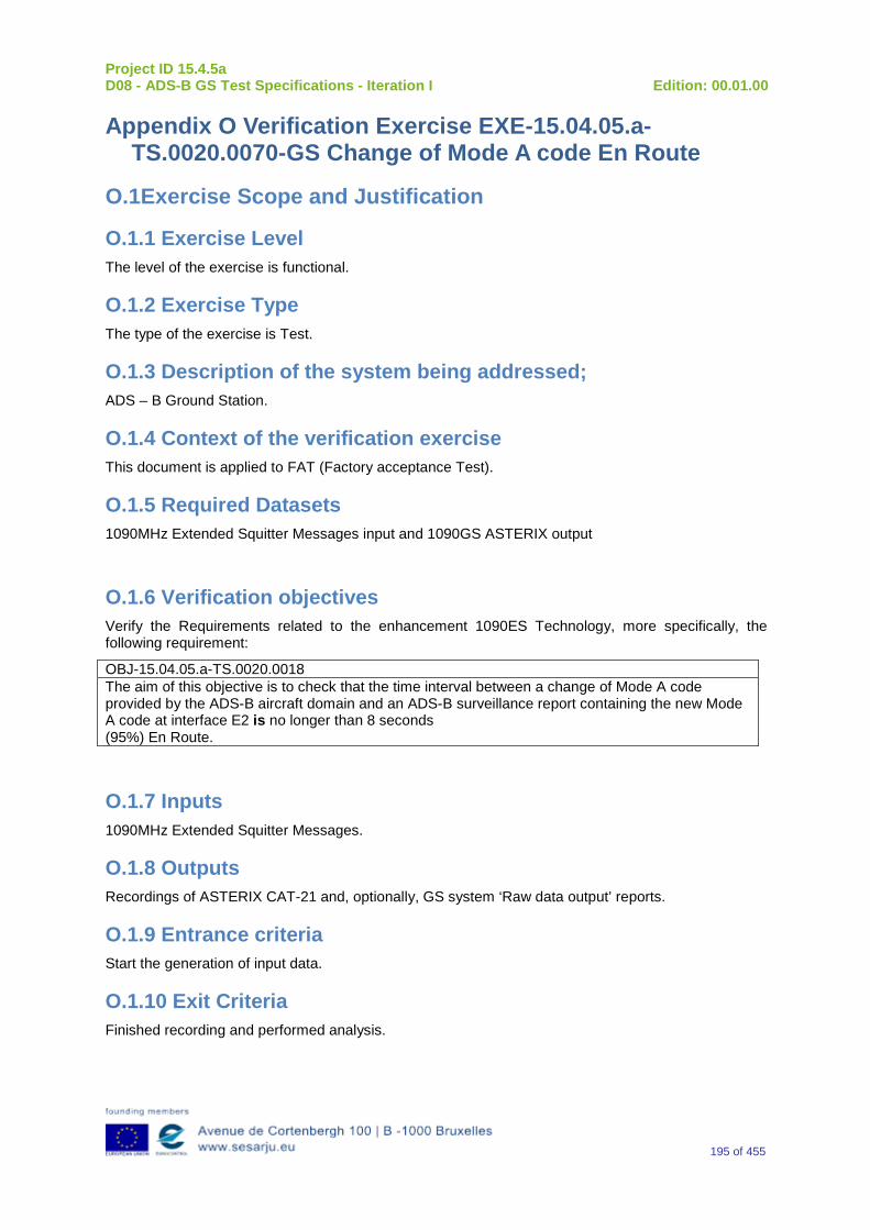
Project ID 15.4.5a D08 - ADS-B GS Test Specifications - Iteration I Edition: 00.01.00
195 of 455
Appendix O Verification Exercise EXE-15.04.05.a-TS.0020.0070-GS Change of Mode A code En Route
O.1Exercise Scope and Justification
O.1.1 Exercise Level The level of the exercise is functional.
O.1.2 Exercise Type The type of the exercise is Test.
O.1.3 Description of the system being addressed; ADS – B Ground Station.
O.1.4 Context of the verification exercise This document is applied to FAT (Factory acceptance Test).
O.1.5 Required Datasets 1090MHz Extended Squitter Messages input and 1090GS ASTERIX output
O.1.6 Verification objectives Verify the Requirements related to the enhancement 1090ES Technology, more specifically, the following requirement:
OBJ-15.04.05.a-TS.0020.0018 The aim of this objective is to check that the time interval between a change of Mode A code provided by the ADS-B aircraft domain and an ADS-B surveillance report containing the new Mode A code at interface E2 is no longer than 8 seconds (95%) En Route.
O.1.7 Inputs 1090MHz Extended Squitter Messages.
O.1.8 Outputs Recordings of ASTERIX CAT-21 and, optionally, GS system ‘Raw data output’ reports.
O.1.9 Entrance criteria Start the generation of input data.
O.1.10 Exit Criteria Finished recording and performed analysis.
Project ID 15.4.5a D08 - ADS-B GS Test Specifications - Iteration I Edition: 00.01.00
196 of 455
O.1.11 Exercise procedure Exercise ID/Title: EXE-15.04.05.a-TS.0020.0070 / Change of Mode A Code Detection Probability for Target in En-Route Airspace
Pass Criteria: This test is passed, when the recorded output has data items and corresponding values as expected.
Exercise Type: Test
Precondition(s): • Test equipment is setup as described above • GS under test is active, and ready for test.
Note(s): N/A
Device(s) in use: SUT is ADS-B GS.
This test procedure verifies that the 1090 ES Ground Station is able to detect a change of Mode A code provided by the ADS-B aircraft and to produce a target report containing updated Mode A data associated with any aircraft in En Route airspace and received from the a/c within the last 8 seconds with a probability of 95%. In order to test the ability to produce a target report, test steps to be done are without FRUIT, with Mode A/C FRUIT overlapping, and with Mode S FRUIT overlapping. Step 1: This test procedure verifies that the 1090 ES Ground Station is able to detect a change of Mode A code provided by the ADS-B aircraft and to produce a target report containing updated Mode A data associated with any aircraft in En Route airspace and received from the a/c within the last 8 seconds in environment without Mode A/C or Mode S FRUIT with a probability of 95%. Connect the Extended Squitter signal source and set the power level at the receiver input equal to the MTL limit required for the UUT equipment class: –84 dBm for A3 equipment class. The scenario shall be done with 100 a/c (100 different Mode S addresses). All a/c shall have 100 different Mode A addresses, which are updated to the new values. ASTERIX output shall be recorded. Compare the output with the known content of the injected input. Any differences that are detected are recorded as an undetected error and that squitter reception is deleted from the count of error free receptions. Additionally compare time of received input with the time when corresponding ASTERIX report was generated. Calculate the measured probability that difference between time of reception and time of output with changed Mode A code is not greater than 8 seconds in 95% cases. Step 2: This test procedure verifies that the 1090 ES Ground Station is able to detect a change of Mode A code provided by the ADS-B aircraft and to produce a target report containing updated Mode A data associated with any aircraft in En Route airspace and received from the a/c within the last 8 seconds in environment with Mode A/C FRUIT with a probability of 95%. Connect the Extended Squitter signal source and set the power level at the receiver input equal to the MTL limit required for the UUT equipment class:
Project ID 15.4.5a D08 - ADS-B GS Test Specifications - Iteration I Edition: 00.01.00
197 of 455
–84 dBm for A3 equipment class. Set the power level of three Mode A/C FRUIT sources at the receiver input to the value corresponding to the UUT equipment class: -76, -72 and –68 dBm for A3 equipment class. Activate the Mode A/C FRUIT source so that the FRUIT is pseudo randomly distributed across the Extended Squitter preamble and data block as specified in §2.4.4.4.2.1 of DO-260B. The scenario shall be done with 100 a/c (100 different Mode S addresses). All a/c shall have 100 different Mode A addresses, which are updated to the new values. ASTERIX output shall be recorded. Compare the output with the known content of the injected input. Any differences that are detected are recorded as an undetected error and that squitter reception is deleted from the count of error free receptions. Additionally compare time of received input with the time when corresponding ASTERIX report was generated. Calculate the measured probability that difference between time of reception and time of output with changed Mode A code is not greater than 8 seconds in 95% cases. Step 3: This test procedure verifies that the 1090 ES Ground Station is able to detect a change of Mode A code provided by the ADS-B aircraft and to produce a target report containing updated Mode A data associated with any aircraft in En Route airspace and received from the a/c within the last 8 seconds in environment with Mode S FRUIT with a probability of 95%. Connect the Extended Squitter signal source and set the power level at the receiver input equal to the MTL limit required for the UUT equipment class plus 12 dB: –72 dBm for A3 equipment class. Set the power level of Mode S FRUIT sources at the receiver input to the value corresponding to the UUT equipment class: -80 dBm for A3 equipment class. Activate the Mode S FRUIT source so that the Mode S FRUIT is pseudo randomly distributed across the data Extended Squitter data block as specified in §2.4.4.4.2.1.2 of DO-260B. The scenario shall be done with 100 a/c (100 different Mode S addresses). All a/c shall have 100 different Mode A addresses, which are updated to the new values. ASTERIX output shall be recorded. Compare the output with the known content of the injected input. Any differences that are detected are recorded as an undetected error and that squitter reception is deleted from the count of error free receptions. Additionally compare time of received input with the time when corresponding ASTERIX report was generated. Calculate the measured probability that difference between time of reception and time of output with changed Mode A code is not greater than 8 seconds in 95% cases.
Exercise Procedure:
Step Action Expected Reaction Pass/Fail Comment
1 Put the GS system under test into the related test configuration.
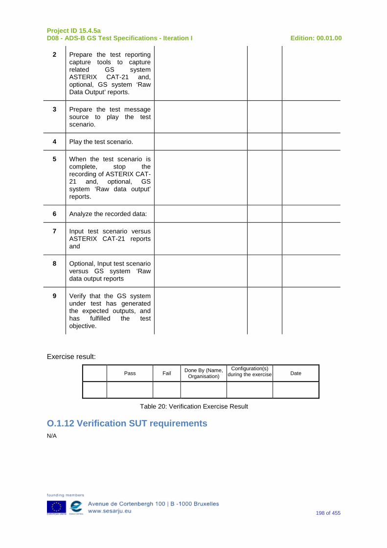
Project ID 15.4.5a D08 - ADS-B GS Test Specifications - Iteration I Edition: 00.01.00
198 of 455
2 Prepare the test reporting capture tools to capture related GS system ASTERIX CAT-21 and, optional, GS system ‘Raw Data Output’ reports.
3 Prepare the test message source to play the test scenario.
4 Play the test scenario.
5 When the test scenario is complete, stop the recording of ASTERIX CAT-21 and, optional, GS system ‘Raw data output’ reports.
6 Analyze the recorded data:
7 Input test scenario versus ASTERIX CAT-21 reports and
8 Optional, Input test scenario versus GS system ‘Raw data output reports
9 Verify that the GS system under test has generated the expected outputs, and has fulfilled the test objective.
Exercise result:
Pass Fail Done By (Name, Organisation)
Configuration(s) during the exercise Date
Table 20: Verification Exercise Result
O.1.12 Verification SUT requirements N/A

Project ID 15.4.5a D08 - ADS-B GS Test Specifications - Iteration I Edition: 00.01.00
199 of 455
O.1.13 Exercise Tool, Verification Technique and/or Platform
ADS-BGround Station
Power
ASTERIX(and Raw Data)
Recording
UTC Time Reference
RF Source(Message Generator)
The Exercise will be verified in a platform with the following foreseen tools/equipment:
-Ground Station ADS–B
-Message Generator
-ASTERIX (and Raw Data) Recording Tool
-Power Source
-UTC time Reference
The Item reported above will be capable to perform the functionalities reported below.
Ground Station ADS-B
The primary function of the 1090 GS is to receive 1090 MHz Mode S Extended Squitter messages, extract the data contained therein, and create appropriated ASTERIX Category 21 and 23 Reports (and optionally, Raw Data).
Message Generator
The Messages Generator will be capable to generate the data coming from the Remote System (ADS–B Ground Station or 1090 Receiver) like:
•Target data stream with inside the information extracted by the ADS–B message (ASTERIX CAT 21 in the case of Ground Station or Raw Data in the case that remote system is a 1090 MHz Receiver).
•Operational Data Stream with inside the Remote System’s Operational Status Information (ASTERIX CAT 23 in the case of Ground Station or Raw Data in the case that remote system is a 1090 MHz Receiver).
UTC Time Reference
The UTC Time reference is the solution adopted in the Test Scenario in order to provide the Synchronization in the Ground Station by UTC Time.
ASTERIX Recording Equipment
The ASTERIX recording equipment will be capable to record all ASTERIX reports sent from the 1090 ES Ground Station.
O.1.14 Verification Platform needs See section 3.5 Verification Platform Needs.
Project ID 15.4.5a D08 - ADS-B GS Test Specifications - Iteration I Edition: 00.01.00
200 of 455
O.1.15 Platform Configuration N/A
O.1.16 Configuration(s) Identification of the Verification Platform N/A
O.1.17 Links to other Verification Exercises N/A
O.1.18 Representatively level/ limitations N/A
O.2 Exercises Planning and management
O.2.1 Activities
O.2.1.1 Preparatory activities Setup the tools/equipment listed in 3.5 and O.1.13 in order to meet the Test Preconditions.
O.2.1.2 Execution activities Play the scenario generating in the input the desired messages and record the relevant ASTERIX (and Raw Data) output.
O.2.1.3 Post execution activities The post execution activities will be mainly focused on the analysis of recorded ASTERIX reports (and Raw Data reports). The analysis shall be done in order to verify the right information propagation as requested in each Test Scenario.
O.2.2 Human Resources. N/A
O.2.3 Responsibilities in the exercise N/A
O.2.4 Training N/A
O.2.5 Time planning N/A
O.2.6 Risks. N/A
O.2.7 Errors and Observation handling N/A

Project ID 15.4.5a D08 - ADS-B GS Test Specifications - Iteration I Edition: 00.01.00
201 of 455
O.3 Analysis Specification
O.3.1 Data collection methods The data collection during the test will be Qualitative. In fact after test execution the analysis of ASTERIX Data will be performed verifying that the values reported in the output are in line with the values generated in the input.
O.3.2 Analysis method N/A
O.3.3 Data logging requirements The data logging requirements for this scenario will foresee at least ASTERIX CAT 21 items.
Project ID 15.4.5a D08 - ADS-B GS Test Specifications - Iteration I Edition: 00.01.00
202 of 455
Appendix P Verification Exercise EXE-15.04.05.a-TS.0020.0080-GS Change of Emergency and SPI Information Detection Probability for Target in En-Route Airspace
P.1Exercise Scope and Justification
P.1.1 Exercise Level The level of the exercise is functional.
P.1.2 Exercise Type The type of the exercise is Test.
P.1.3 Description of the system being addressed; ADS – B Ground Station.
P.1.4 Context of the verification exercise This document is applied to FAT (Factory acceptance Test).
P.1.5 Required Datasets 1090MHz Extended Squitter Messages input and 1090GS ASTERIX output
P.1.6 Verification objectives Verify the Requirements related to the enhancement 1090ES Technology, more specifically, the following requirement:
OBJ-15.04.05.a-TS.0020.0019 The aim of this objective is to check that the time interval between a change of emergency and SPI information provided by the ADS-B aircraft domain and an ADS-B surveillance report containing the new emergency and SPI information at interface E2 is no longer than 8 seconds (95%) En Route.
P.1.7 Inputs 1090MHz Extended Squitter Messages.
P.1.8 Outputs Recordings of ASTERIX CAT-21 and, optionally, GS system ‘Raw data output’ reports.
P.1.9 Entrance criteria Start the generation of input data.
Project ID 15.4.5a D08 - ADS-B GS Test Specifications - Iteration I Edition: 00.01.00
203 of 455
P.1.10 Exit Criteria Finished recording and performed analysis.
P.1.11 Exercise procedure Exercise ID/Title: EXE-15.04.05.a-TS.0020.0080 / Change of Emergency and SPI Information Detection Probability for Target in En-Route Airspace Pass Criteria: This test is passed, when the recorded output has data items and
corresponding values as expected.
Exercise Type: Test
Precondition(s): • Test equipment is setup as described above • GS under test is active, and ready for test.
Note(s): N/A
Device(s) in use: SUT is ADS-B GS.
This test procedure verifies that the 1090 ES Ground Station is able to detect a change of emergency and SPI information provided by the ADS-B aircraft and to produce a target report containing updated emergency and SPI information data associated with any aircraft in En Route airspace and received from the a/c within the last 8 seconds with a probability of 95%. In order to test the ability to produce a target report, test steps to be done are without FRUIT, with Mode A/C FRUIT overlapping, and with Mode S FRUIT overlapping. Step 1: This test procedure verifies that the 1090 ES Ground Station is able to detect a change of emergency and SPI information provided by the ADS-B aircraft and to produce a target report containing updated emergency and SPI information data associated with any aircraft in En Route airspace and received from the a/c within the last 8 seconds in environment without Mode A/C or Mode S FRUIT with a probability of 95%. Connect the Extended Squitter signal source and set the power level at the receiver input equal to the MTL limit required for the UUT equipment class: –84 dBm for A3 equipment class. The scenario shall be done with 100 a/c (100 different Mode S addresses). All a/c shall have initial emergency and SPI information, which are updated to the new values. ASTERIX output shall be recorded. Compare the output with the known content of the injected input. Any differences that are detected are recorded as an undetected error and that squitter reception is deleted from the count of error free receptions. Additionally compare time of received input with the time when corresponding ASTERIX report was generated. Calculate the measured probability that difference between time of receive and time of output with changed emergency and SPI information is not greater than 8 seconds in 95% cases. Step 2:
Project ID 15.4.5a D08 - ADS-B GS Test Specifications - Iteration I Edition: 00.01.00
204 of 455
This test procedure verifies that the 1090 ES Ground Station is able to detect a change of emergency and SPI information provided by the ADS-B aircraft and to produce a target report containing updated emergency and SPI information data associated with any aircraft in En Route airspace and received from the a/c within the last 8 seconds in environment with Mode A/C FRUIT with a probability of 95%. Connect the Extended Squitter signal source and set the power level at the receiver input equal to the MTL limit required for the UUT equipment class: –84 dBm for A3 equipment class. Set the power level of three Mode A/C FRUIT sources at the receiver input to the value corresponding to the UUT equipment class: -76, -72 and –68 dBm for A3 equipment class. Activate the Mode A/C FRUIT source so that the FRUIT is pseudo randomly distributed across the Extended Squitter preamble and data block as specified in §2.4.4.4.2.1 of DO-260B. The scenario shall be done with 100 a/c (100 different Mode S addresses). All a/c shall have initial emergency and SPI information, which are updated to the new values. ASTERIX output shall be recorded. Compare the output with the known content of the injected input. Any differences that are detected are recorded as an undetected error and that squitter reception is deleted from the count of error free receptions. Additionally compare time of received input with the time when corresponding ASTERIX report was generated. Calculate the measured probability that difference between time of receive and time of output with changed emergency and SPI information is not greater than 8 seconds in 95% cases. Step 3: This test procedure verifies that the 1090 ES Ground Station is able to detect a change of emergency and SPI information provided by the ADS-B aircraft and to produce a target report containing updated emergency and SPI information data associated with any aircraft in En Route airspace and received from the a/c within the last 8 seconds in environment with Mode S FRUIT with a probability of 95%. Connect the Extended Squitter signal source and set the power level at the receiver input equal to the MTL limit required for the UUT equipment class plus 12 dB: –72 dBm for A3 equipment class. Set the power level of Mode S FRUIT sources at the receiver input to the value corresponding to the UUT equipment class: -80 dBm for A3 equipment class. Activate the Mode S FRUIT source so that the Mode S FRUIT is pseudo randomly distributed across the data Extended Squitter data block as specified in §2.4.4.4.2.1.2 of DO-260B. The scenario shall be done with 100 a/c (100 different Mode S addresses). All a/c shall have initial emergency and SPI information, which are updated to the new values. ASTERIX output shall be recorded. Compare the output with the known content of the injected input. Any differences that are detected are recorded as an undetected error and that squitter reception is deleted from the count of error free receptions. Additionally compare time of received input with the time when corresponding ASTERIX report was generated. Calculate the measured probability that difference between time of receive and time of output with changed emergency and SPI information is not greater than 8 seconds in 95% cases.
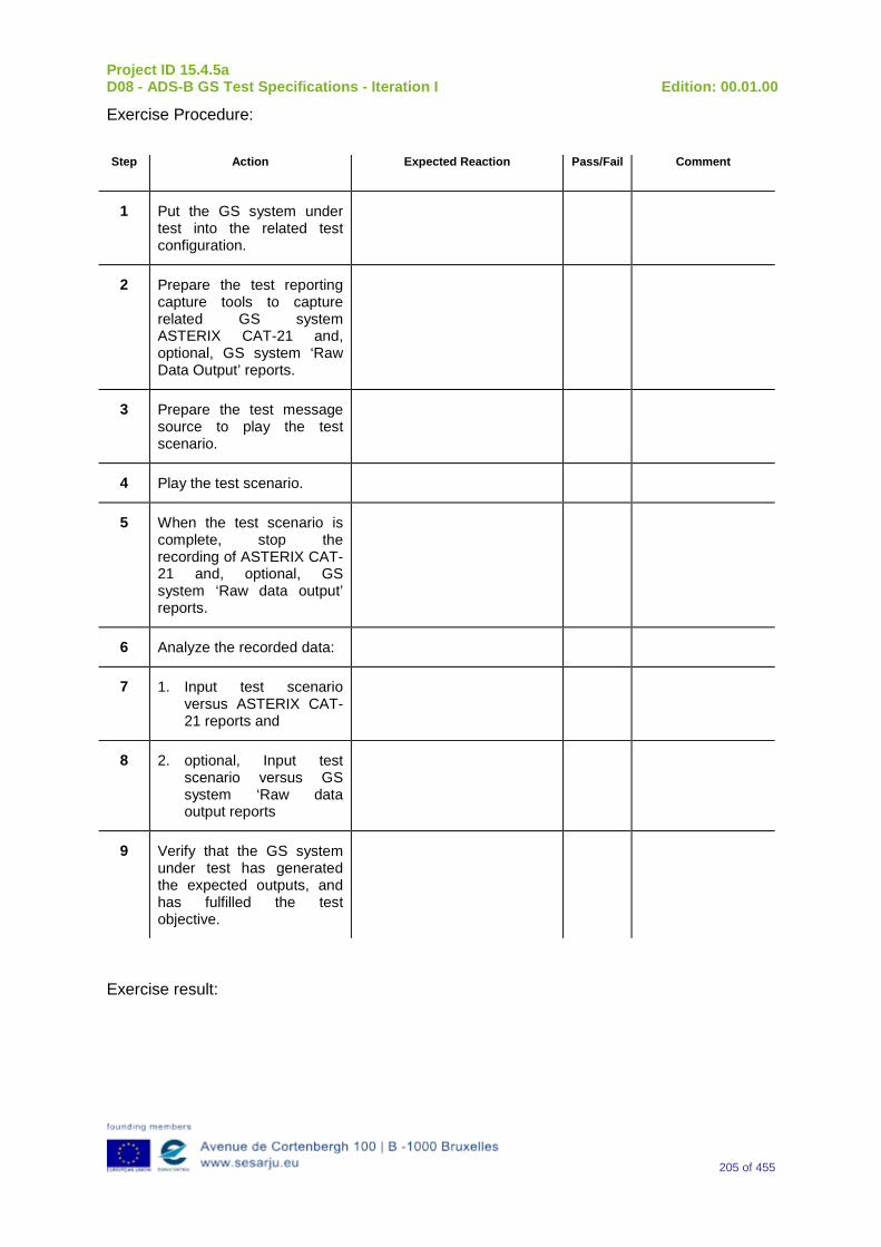
Project ID 15.4.5a D08 - ADS-B GS Test Specifications - Iteration I Edition: 00.01.00
205 of 455
Exercise Procedure:
Step Action Expected Reaction Pass/Fail Comment
1 Put the GS system under test into the related test configuration.
2 Prepare the test reporting capture tools to capture related GS system ASTERIX CAT-21 and, optional, GS system ‘Raw Data Output’ reports.
3 Prepare the test message source to play the test scenario.
4 Play the test scenario.
5 When the test scenario is complete, stop the recording of ASTERIX CAT-21 and, optional, GS system ‘Raw data output’ reports.
6 Analyze the recorded data:
7 1. Input test scenario versus ASTERIX CAT-21 reports and
8 2. optional, Input test scenario versus GS system ‘Raw data output reports
9 Verify that the GS system under test has generated the expected outputs, and has fulfilled the test objective.
Exercise result:
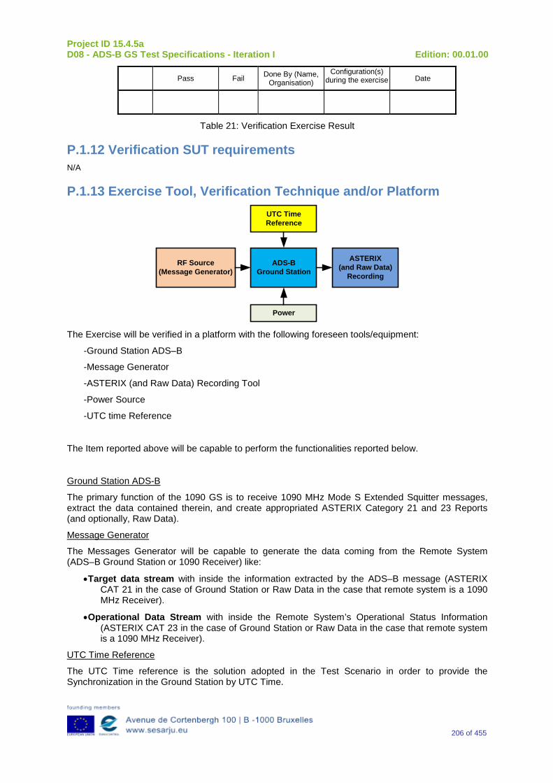
Project ID 15.4.5a D08 - ADS-B GS Test Specifications - Iteration I Edition: 00.01.00
206 of 455
Pass Fail Done By (Name, Organisation)
Configuration(s) during the exercise Date
Table 21: Verification Exercise Result
P.1.12 Verification SUT requirements N/A
P.1.13 Exercise Tool, Verification Technique and/or Platform
ADS-BGround Station
Power
ASTERIX(and Raw Data)
Recording
UTC Time Reference
RF Source(Message Generator)
The Exercise will be verified in a platform with the following foreseen tools/equipment:
-Ground Station ADS–B
-Message Generator
-ASTERIX (and Raw Data) Recording Tool
-Power Source
-UTC time Reference
The Item reported above will be capable to perform the functionalities reported below.
Ground Station ADS-B
The primary function of the 1090 GS is to receive 1090 MHz Mode S Extended Squitter messages, extract the data contained therein, and create appropriated ASTERIX Category 21 and 23 Reports (and optionally, Raw Data).
Message Generator
The Messages Generator will be capable to generate the data coming from the Remote System (ADS–B Ground Station or 1090 Receiver) like:
•Target data stream with inside the information extracted by the ADS–B message (ASTERIX CAT 21 in the case of Ground Station or Raw Data in the case that remote system is a 1090 MHz Receiver).
•Operational Data Stream with inside the Remote System’s Operational Status Information (ASTERIX CAT 23 in the case of Ground Station or Raw Data in the case that remote system is a 1090 MHz Receiver).
UTC Time Reference
The UTC Time reference is the solution adopted in the Test Scenario in order to provide the Synchronization in the Ground Station by UTC Time.
Project ID 15.4.5a D08 - ADS-B GS Test Specifications - Iteration I Edition: 00.01.00
207 of 455
ASTERIX Recording Equipment
The ASTERIX recording equipment will be capable to record all ASTERIX reports sent from the 1090 ES Ground Station.
P.1.14 Verification Platform needs See section 3.5 Verification Platform Needs.
P.1.15 Platform Configuration N/A
P.1.16 Configuration(s) Identification of the Verification Platform N/A
P.1.17 Links to other Verification Exercises N/A
P.1.18 Representatively level/ limitations N/A
P.2 Exercises Planning and management
P.2.1 Activities
P.2.1.1 Preparatory activities Setup the tools/equipment listed in 3.5 and P.1.13 in order to meet the Test Preconditions.
P.2.1.2 Execution activities Play the scenario generating in the input the desired messages and record the relevant ASTERIX (and Raw Data) output.
P.2.1.3 Post execution activities The post execution activities will be mainly focused on the analysis of recorded ASTERIX reports (and Raw Data reports). The analysis shall be done in order to verify the right information propagation as requested in each Test Scenario.
P.2.2 Human Resources. N/A
P.2.3 Responsibilities in the exercise N/A
P.2.4 Training N/A
Project ID 15.4.5a D08 - ADS-B GS Test Specifications - Iteration I Edition: 00.01.00
208 of 455
P.2.5 Time planning N/A
P.2.6 Risks. N/A
P.2.7 Errors and Observation handling N/A
P.3 Analysis Specification
P.3.1 Data collection methods The data collection during the test will be Qualitative. In fact after test execution the analysis of ASTERIX Data will be performed verifying that the values reported in the output are in line with the values generated in the input.
P.3.2 Analysis method N/A
P.3.3 Data logging requirements The data logging requirements for this scenario will foresee at least ASTERIX CAT 21 items.
Project ID 15.4.5a D08 - ADS-B GS Test Specifications - Iteration I Edition: 00.01.00
209 of 455
Appendix Q Verification Exercise EXE-15.04.05.a-TS.0020.0090-GS Report Probability for Target in TMA Airspace
Q.1Exercise Scope and Justification
Q.1.1 Exercise Level The level of the exercise is functional.
Q.1.2 Exercise Type The type of the exercise is Test.
Q.1.3 Description of the system being addressed; ADS – B Ground Station.
Q.1.4 Context of the verification exercise This document is applied to FAT (Factory acceptance Test).
Q.1.5 Required Datasets 1090MHz Extended Squitter Messages input and 1090GS ASTERIX output
Q.1.6 Verification objectives Verify the Requirements related to the enhancement 1090ES Technology, more specifically, the following requirement:
OBJ-15.04.05.a-TS.0020.0021 The aim of this objective is to check that the probability of providing a Surveillance Report containing newly received ADS-B Position data of sufficient quality associated with any aircraft in TMA airspace within 5 seconds is 97%. Notes: 1. Additional requirements are subject to local implementation. Other considerations may apply (see OSA: C.5.1.5 - “Loss of track information”). 2. Data continuity for a single aircraft is inherently encompassed by the requirements for position update, i.e. in terms of the number of consecutive misses of receiving a position update ultimately leading to a track drop. The required position update probability takes account of normal environmental factors that are experienced during this flight phase, such as coverage variations in received signals (including received satellite signals), that affect the production and receipt of ADS-B positions of sufficient quality on a single aircraft basis. Multiple aircraft data continuity is addressed in ASSUMP 24.
Q.1.7 Inputs 1090MHz Extended Squitter Messages.
Project ID 15.4.5a D08 - ADS-B GS Test Specifications - Iteration I Edition: 00.01.00
210 of 455
Q.1.8 Outputs Recordings of ASTERIX CAT-21 and, optionally, GS system ‘Raw data output’ reports.
Q.1.9 Entrance criteria Start the generation of input data.
Q.1.10 Exit Criteria Finished recording and performed analysis.
Q.1.11 Exercise procedure Exercise ID/Title: EXE-15.04.05.a-TS.0020.0090 / Report Probability for Target in TMA Airspace Pass Criteria: This test is passed, when the recorded output has data items and
corresponding values as expected.
Exercise Type: Test
Precondition(s): • Test equipment is setup as described above • GS under test is active, and ready for test.
Note(s): N/A
Device(s) in use: SUT is ADS-B GS.
This test procedure verifies that the 1090 ES Ground Station is able to produce a target report containing ADS-B Position data associated with any aircraft in TMA airspace and received from the a/c within the last 5 seconds with a probability of 97%. In order to test the ability to produce a target report, test steps to be done are without FRUIT, with Mode A/C FRUIT overlapping, and with Mode S FRUIT overlapping. Step 1: This test step verifies that the 1090 ES Ground Station is able to produce a target report containing ADS-B Position data associated with any aircraft in En Route airspace and received from the a/c within the last 5 seconds in environment without Mode A/C or Mode S FRUIT with a probability of 97%. Connect the Extended Squitter signal source and set the power level at the receiver input equal to the MTL limit required for the UUT equipment class: –84 dBm for A3 equipment class. The scenario shall be done with 100 a/c (100 different Mode S addresses). ASTERIX output shall be recorded. Compare the output with the known content of the injected input. Any differences that are detected are recorded as an undetected error and that squitter reception is deleted from the count of error free receptions. Additionally compare time of received input with the time when corresponding ASTERIX report was generated. Calculate the measured probability that difference between time of receive and time of output is not greater than 8 seconds in 97% cases. Step 2:
Project ID 15.4.5a D08 - ADS-B GS Test Specifications - Iteration I Edition: 00.01.00
211 of 455
This test step verifies that the 1090 ES Ground Station is able to produce a target report containing ADS-B Position data associated with any aircraft in En Route airspace and received from the a/c within the last 5 seconds in environment with Mode A/C FRUIT with a probability of 97%. Connect the Extended Squitter signal source and set the power level at the receiver input equal to the MTL limit required for the UUT equipment class: –84 dBm for A3 equipment class. Set the power level of three Mode A/C FRUIT sources at the receiver input to the value corresponding to the UUT equipment class: -76, -72 and –68 dBm for A3 equipment class. Activate the Mode A/C FRUIT source so that the FRUIT is pseudo randomly distributed across the Extended Squitter preamble and data block as specified in §2.4.4.4.2.1 of DO-260B. The scenario shall be done with 100 a/c (100 different Mode S addresses). ASTERIX output shall be recorded. Compare the output with the known content of the injected input. Any differences that are detected are recorded as an undetected error and that squitter reception is deleted from the count of error free receptions. Additionally compare time of received input with the time when corresponding ASTERIX report was generated. Calculate the measured probability that difference between time of receive and time of output is not greater than 8 seconds in 97% cases. Step 3: This test step verifies that the 1090 ES Ground Station is able to produce a target report containing ADS-B Position data associated with any aircraft in En Route airspace and received from the a/c within the last 5 seconds in environment with Mode S FRUIT with a probability of 97%. Connect the Extended Squitter signal source and set the power level at the receiver input equal to the MTL limit required for the UUT equipment class plus 12 dB: –72 dBm for A3 equipment class. Set the power level of Mode S FRUIT sources at the receiver input to the value corresponding to the UUT equipment class: -80 dBm for A3 equipment class. Activate the Mode S FRUIT source so that the Mode S FRUIT is pseudo randomly distributed across the data Extended Squitter data block as specified in §2.4.4.4.2.1.2 of DO-260B. The scenario shall be done with 100 a/c (100 different Mode S addresses). ASTERIX output shall be recorded. Compare the output with the known content of the injected input. Any differences that are detected are recorded as an undetected error and that squitter reception is deleted from the count of error free receptions. Additionally compare time of received input with the time when corresponding ASTERIX report was generated. Calculate the measured probability that difference between time of receive and time of output is not greater than 8 seconds in 97% cases.
Exercise Procedure:
Step Action Expected Reaction Pass/Fail Comment
1 Put the GS system under test into the related test
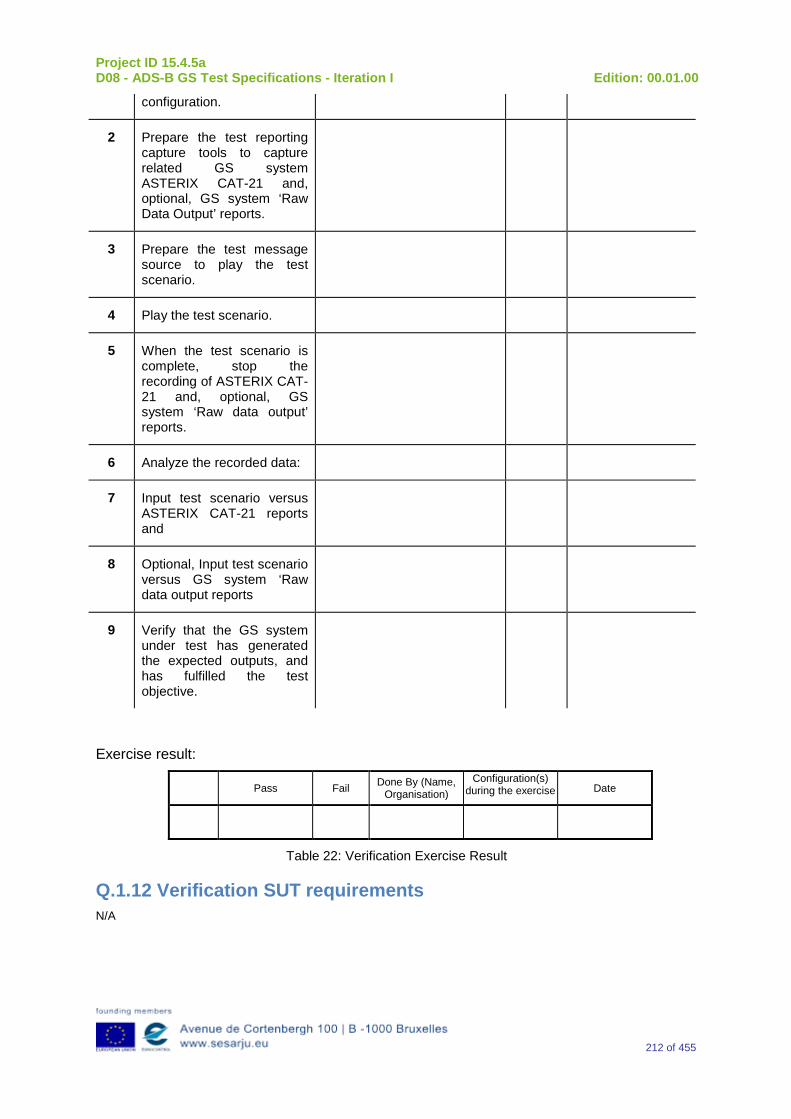
Project ID 15.4.5a D08 - ADS-B GS Test Specifications - Iteration I Edition: 00.01.00
212 of 455
configuration.
2 Prepare the test reporting capture tools to capture related GS system ASTERIX CAT-21 and, optional, GS system ‘Raw Data Output’ reports.
3 Prepare the test message source to play the test scenario.
4 Play the test scenario.
5 When the test scenario is complete, stop the recording of ASTERIX CAT-21 and, optional, GS system ‘Raw data output’ reports.
6 Analyze the recorded data:
7 Input test scenario versus ASTERIX CAT-21 reports and
8 Optional, Input test scenario versus GS system ‘Raw data output reports
9 Verify that the GS system under test has generated the expected outputs, and has fulfilled the test objective.
Exercise result:
Pass Fail Done By (Name, Organisation)
Configuration(s) during the exercise Date
Table 22: Verification Exercise Result
Q.1.12 Verification SUT requirements N/A

Project ID 15.4.5a D08 - ADS-B GS Test Specifications - Iteration I Edition: 00.01.00
213 of 455
Q.1.13 Exercise Tool, Verification Technique and/or Platform
ADS-BGround Station
Power
ASTERIX(and Raw Data)
Recording
UTC Time Reference
RF Source(Message Generator)
The Exercise will be verified in a platform with the following foreseen tools/equipment:
-Ground Station ADS–B
-Message Generator
-ASTERIX (and Raw Data) Recording Tool
-Power Source
-UTC time Reference.
The Item reported above will be capable to perform the functionalities reported below.
Ground Station ADS-B
The primary function of the 1090 GS is to receive 1090 MHz Mode S Extended Squitter messages, extract the data contained therein, and create appropriated ASTERIX Category 21 and 23 Reports (and optionally, Raw Data).
Message Generator
The Messages Generator will be capable to generate the data coming from the Remote System (ADS–B Ground Station or 1090 Receiver) like:
•Target data stream with inside the information extracted by the ADS–B message (ASTERIX CAT 21 in the case of Ground Station or Raw Data in the case that remote system is a 1090 MHz Receiver).
•Operational Data Stream with inside the Remote System’s Operational Status Information (ASTERIX CAT 23 in the case of Ground Station or Raw Data in the case that remote system is a 1090 MHz Receiver).
UTC Time Reference
The UTC Time reference is the solution adopted in the Test Scenario in order to provide the Synchronization in the Ground Station by UTC Time.
ASTERIX Recording Equipment
The ASTERIX recording equipment will be capable to record all ASTERIX reports sent from the 1090 ES Ground Station.
Q.1.14 Verification Platform needs See section 3.5 Verification Platform Needs.
Project ID 15.4.5a D08 - ADS-B GS Test Specifications - Iteration I Edition: 00.01.00
214 of 455
Q.1.15 Platform Configuration N/A
Q.1.16 Configuration(s) Identification of the Verification Platform N/A
Q.1.17 Links to other Verification Exercises N/A
Q.1.18 Representatively level/ limitations N/A
Q.2 Exercises Planning and management
Q.2.1 Activities
Q.2.1.1Preparatory activities Setup the tools/equipment listed in 3.5 and Q.1.13 in order to meet the Test Preconditions.
Q.2.1.2 Execution activities Play the scenario generating in the input the desired messages and record the relevant ASTERIX (and Raw Data) output.
Q.2.1.3 Post execution activities The post execution activities will be mainly focused on the analysis of recorded ASTERIX reports (and Raw Data reports). The analysis shall be done in order to verify the right information propagation as requested in each Test Scenario.
Q.2.2 Human Resources. N/A
Q.2.3 Responsibilities in the exercise N/A
Q.2.4 Training N/A
Q.2.5 Time planning N/A
Q.2.6 Risks. N/A
Q.2.7 Errors and Observation handling N/A

Project ID 15.4.5a D08 - ADS-B GS Test Specifications - Iteration I Edition: 00.01.00
215 of 455
Q.3 Analysis Specification
Q.3.1 Data collection methods The data collection during the test will be Qualitative. In fact after test execution the analysis of ASTERIX Data will be performed verifying that the values reported in the output are in line with the values generated in the input.
Q.3.2 Analysis method N/A
Q.3.3 Data logging requirements The data logging requirements for this scenario will foresee at least ASTERIX CAT 21 items.
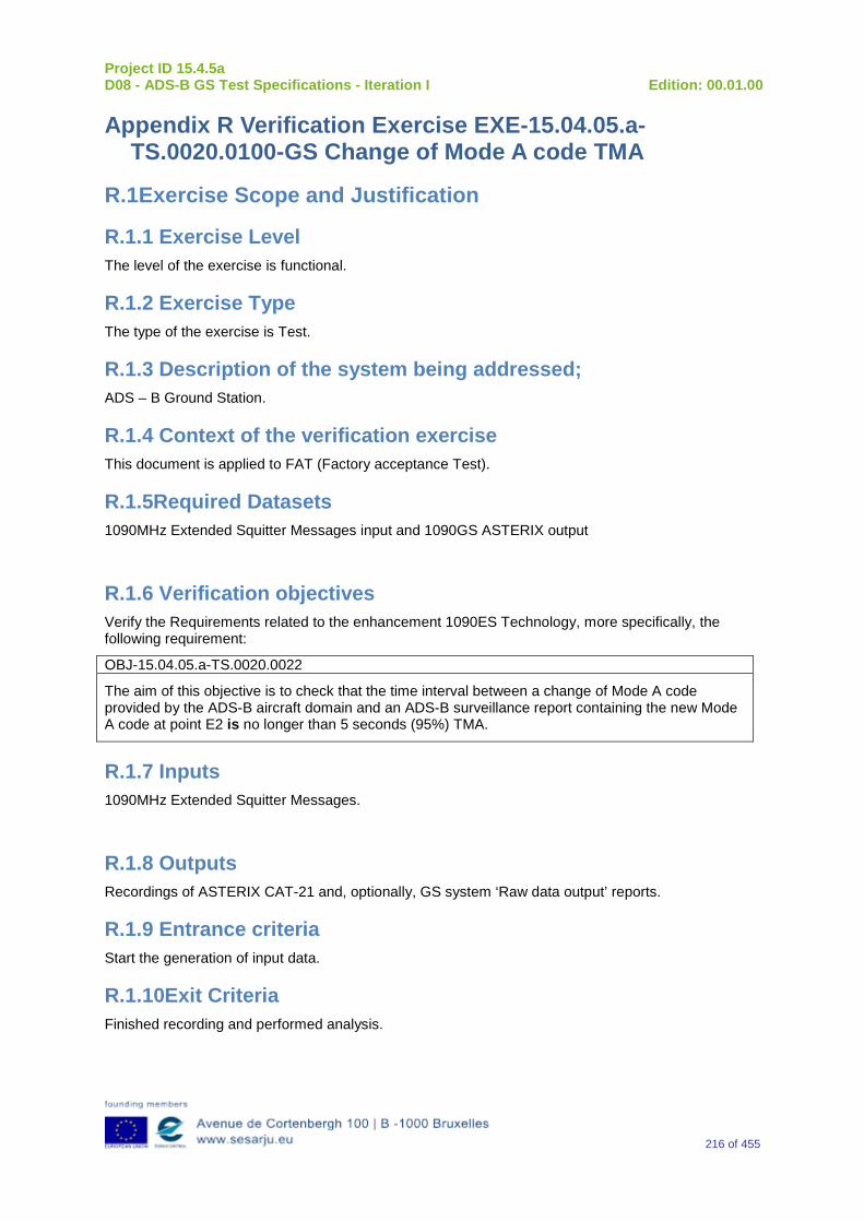
Project ID 15.4.5a D08 - ADS-B GS Test Specifications - Iteration I Edition: 00.01.00
216 of 455
Appendix R Verification Exercise EXE-15.04.05.a-TS.0020.0100-GS Change of Mode A code TMA
R.1Exercise Scope and Justification
R.1.1 Exercise Level The level of the exercise is functional.
R.1.2 Exercise Type The type of the exercise is Test.
R.1.3 Description of the system being addressed; ADS – B Ground Station.
R.1.4 Context of the verification exercise This document is applied to FAT (Factory acceptance Test).
R.1.5Required Datasets 1090MHz Extended Squitter Messages input and 1090GS ASTERIX output
R.1.6 Verification objectives Verify the Requirements related to the enhancement 1090ES Technology, more specifically, the following requirement:
OBJ-15.04.05.a-TS.0020.0022
The aim of this objective is to check that the time interval between a change of Mode A code provided by the ADS-B aircraft domain and an ADS-B surveillance report containing the new Mode A code at point E2 is no longer than 5 seconds (95%) TMA.
R.1.7 Inputs 1090MHz Extended Squitter Messages.
R.1.8 Outputs Recordings of ASTERIX CAT-21 and, optionally, GS system ‘Raw data output’ reports.
R.1.9 Entrance criteria Start the generation of input data.
R.1.10Exit Criteria Finished recording and performed analysis.
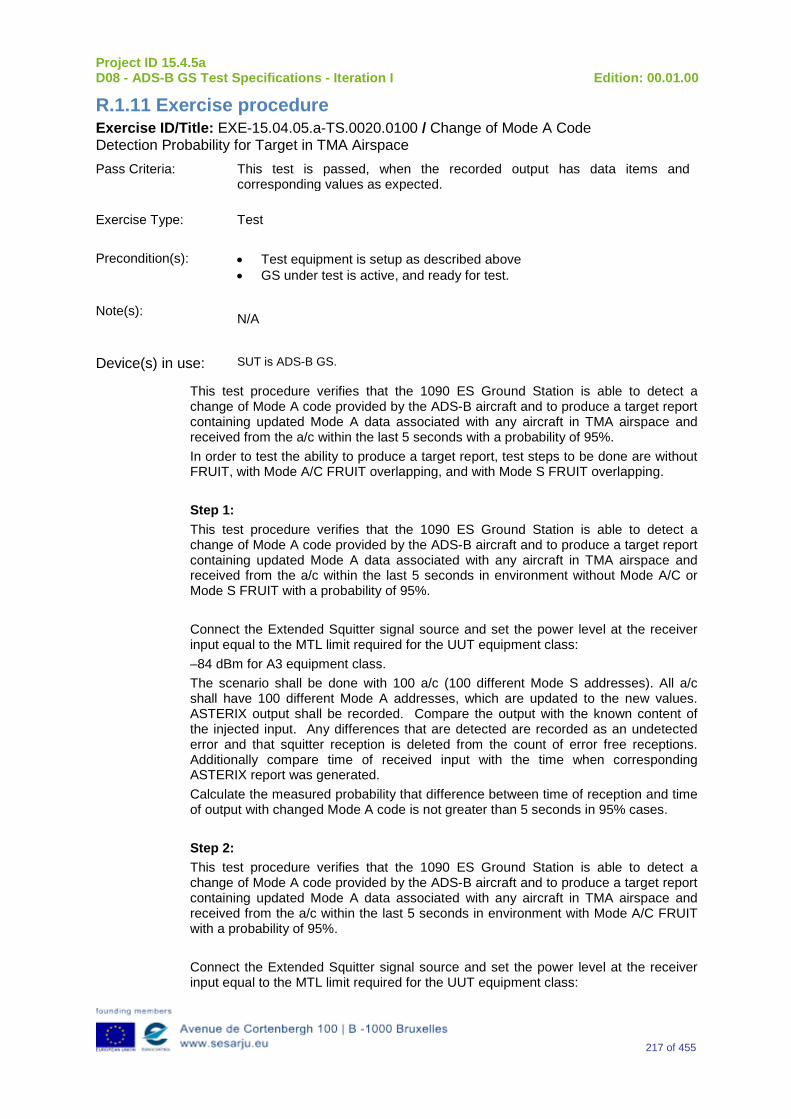
Project ID 15.4.5a D08 - ADS-B GS Test Specifications - Iteration I Edition: 00.01.00
217 of 455
R.1.11 Exercise procedure Exercise ID/Title: EXE-15.04.05.a-TS.0020.0100 / Change of Mode A Code Detection Probability for Target in TMA Airspace Pass Criteria: This test is passed, when the recorded output has data items and
corresponding values as expected.
Exercise Type: Test
Precondition(s): • Test equipment is setup as described above • GS under test is active, and ready for test.
Note(s): N/A
Device(s) in use: SUT is ADS-B GS.
This test procedure verifies that the 1090 ES Ground Station is able to detect a change of Mode A code provided by the ADS-B aircraft and to produce a target report containing updated Mode A data associated with any aircraft in TMA airspace and received from the a/c within the last 5 seconds with a probability of 95%. In order to test the ability to produce a target report, test steps to be done are without FRUIT, with Mode A/C FRUIT overlapping, and with Mode S FRUIT overlapping. Step 1: This test procedure verifies that the 1090 ES Ground Station is able to detect a change of Mode A code provided by the ADS-B aircraft and to produce a target report containing updated Mode A data associated with any aircraft in TMA airspace and received from the a/c within the last 5 seconds in environment without Mode A/C or Mode S FRUIT with a probability of 95%. Connect the Extended Squitter signal source and set the power level at the receiver input equal to the MTL limit required for the UUT equipment class: –84 dBm for A3 equipment class. The scenario shall be done with 100 a/c (100 different Mode S addresses). All a/c shall have 100 different Mode A addresses, which are updated to the new values. ASTERIX output shall be recorded. Compare the output with the known content of the injected input. Any differences that are detected are recorded as an undetected error and that squitter reception is deleted from the count of error free receptions. Additionally compare time of received input with the time when corresponding ASTERIX report was generated. Calculate the measured probability that difference between time of reception and time of output with changed Mode A code is not greater than 5 seconds in 95% cases. Step 2: This test procedure verifies that the 1090 ES Ground Station is able to detect a change of Mode A code provided by the ADS-B aircraft and to produce a target report containing updated Mode A data associated with any aircraft in TMA airspace and received from the a/c within the last 5 seconds in environment with Mode A/C FRUIT with a probability of 95%. Connect the Extended Squitter signal source and set the power level at the receiver input equal to the MTL limit required for the UUT equipment class:
Project ID 15.4.5a D08 - ADS-B GS Test Specifications - Iteration I Edition: 00.01.00
218 of 455
–84 dBm for A3 equipment class. Set the power level of three Mode A/C FRUIT sources at the receiver input to the value corresponding to the UUT equipment class: -76, -72 and –68 dBm for A3 equipment class. Activate the Mode A/C FRUIT source so that the FRUIT is pseudo randomly distributed across the Extended Squitter preamble and data block as specified in §2.4.4.4.2.1 of DO-260B. The scenario shall be done with 100 a/c (100 different Mode S addresses). All a/c shall have 100 different Mode A addresses, which are updated to the new values. ASTERIX output shall be recorded. Compare the output with the known content of the injected input. Any differences that are detected are recorded as an undetected error and that squitter reception is deleted from the count of error free receptions. Additionally compare time of received input with the time when corresponding ASTERIX report was generated. Calculate the measured probability that difference between time of reception and time of output with changed Mode A code is not greater than 5 seconds in 95% cases. Step 3: This test procedure verifies that the 1090 ES Ground Station is able to detect a change of Mode A code provided by the ADS-B aircraft and to produce a target report containing updated Mode A data associated with any aircraft in TMA airspace and received from the a/c within the last 5 seconds in environment with Mode S FRUIT with a probability of 95%. Connect the Extended Squitter signal source and set the power level at the receiver input equal to the MTL limit required for the UUT equipment class plus 12 dB: –72 dBm for A3 equipment class. Set the power level of Mode S FRUIT sources at the receiver input to the value corresponding to the UUT equipment class: -80 dBm for A3 equipment class. Activate the Mode S FRUIT source so that the Mode S FRUIT is pseudo randomly distributed across the data Extended Squitter data block as specified in §2.4.4.4.2.1.2 of DO-260B. The scenario shall be done with 100 a/c (100 different Mode S addresses). All a/c shall have 100 different Mode A addresses, which are updated to the new values. ASTERIX output shall be recorded. Compare the output with the known content of the injected input. Any differences that are detected are recorded as an undetected error and that squitter reception is deleted from the count of error free receptions. Additionally compare time of received input with the time when corresponding ASTERIX report was generated. Calculate the measured probability that difference between time of reception and time of output with changed Mode A code is not greater than 5 seconds in 95% cases.
Exercise Procedure:

Project ID 15.4.5a D08 - ADS-B GS Test Specifications - Iteration I Edition: 00.01.00
219 of 455
Step Action Expected Reaction Pass/Fail Comment
1 Put the GS system under test into the related test configuration.
2 Prepare the test reporting capture tools to capture related GS system ASTERIX CAT-21 and, optional, GS system ‘Raw Data Output’ reports.
3 Prepare the test message source to play the test scenario.
4 Play the test scenario.
5 When the test scenario is complete, stop the recording of ASTERIX CAT-21 and, optional, GS system ‘Raw data output’ reports.
6 Analyze the recorded data:
7 Input test scenario versus ASTERIX CAT-21 reports and
8 Optional, Input test scenario versus GS system ‘Raw data output reports
9 Verify that the GS system under test has generated the expected outputs, and has fulfilled the test objective.
Exercise result:
Pass Fail Done By (Name, Organisation)
Configuration(s) during the exercise Date
Table 23: Verification Exercise Result
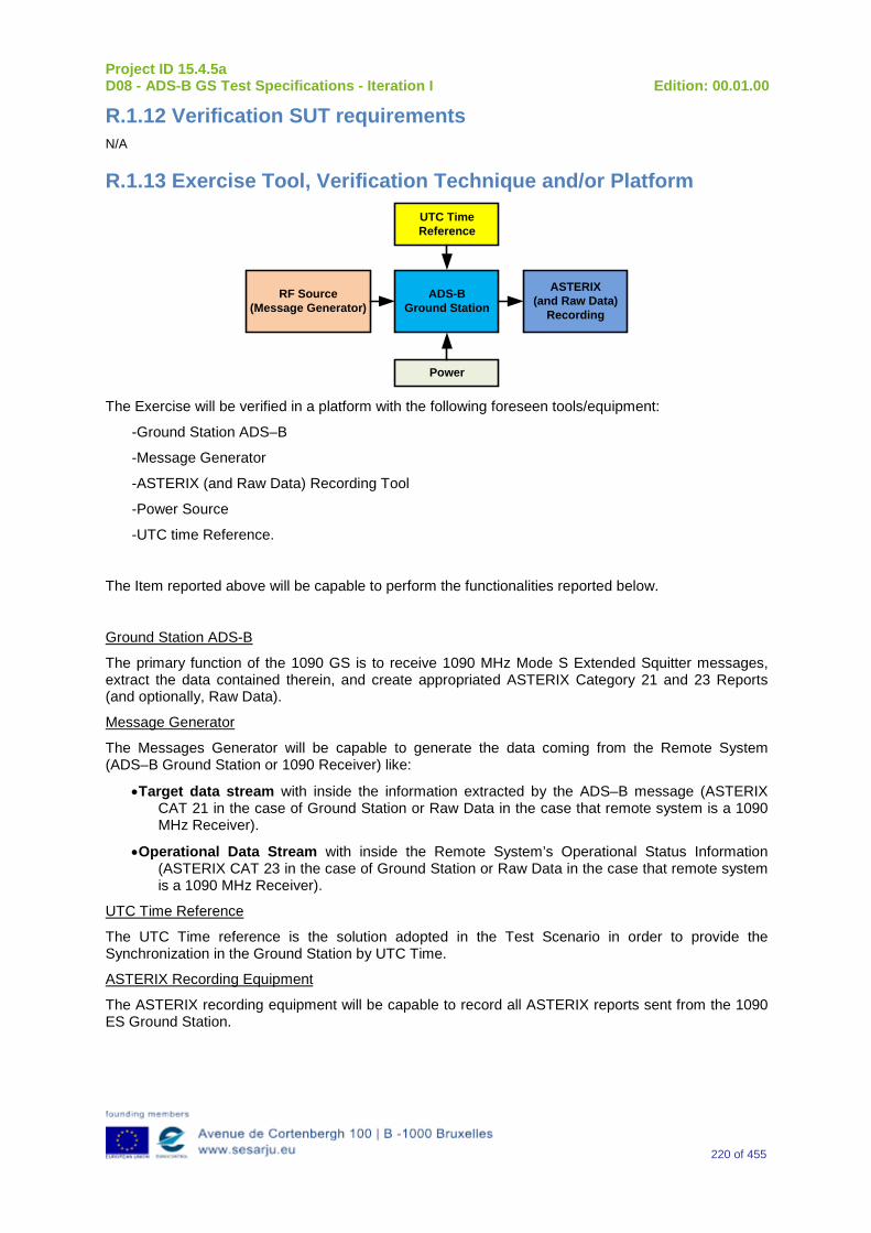
Project ID 15.4.5a D08 - ADS-B GS Test Specifications - Iteration I Edition: 00.01.00
220 of 455
R.1.12 Verification SUT requirements N/A
R.1.13 Exercise Tool, Verification Technique and/or Platform
ADS-BGround Station
Power
ASTERIX(and Raw Data)
Recording
UTC Time Reference
RF Source(Message Generator)
The Exercise will be verified in a platform with the following foreseen tools/equipment:
-Ground Station ADS–B
-Message Generator
-ASTERIX (and Raw Data) Recording Tool
-Power Source
-UTC time Reference.
The Item reported above will be capable to perform the functionalities reported below.
Ground Station ADS-B
The primary function of the 1090 GS is to receive 1090 MHz Mode S Extended Squitter messages, extract the data contained therein, and create appropriated ASTERIX Category 21 and 23 Reports (and optionally, Raw Data).
Message Generator
The Messages Generator will be capable to generate the data coming from the Remote System (ADS–B Ground Station or 1090 Receiver) like:
•Target data stream with inside the information extracted by the ADS–B message (ASTERIX CAT 21 in the case of Ground Station or Raw Data in the case that remote system is a 1090 MHz Receiver).
•Operational Data Stream with inside the Remote System’s Operational Status Information (ASTERIX CAT 23 in the case of Ground Station or Raw Data in the case that remote system is a 1090 MHz Receiver).
UTC Time Reference
The UTC Time reference is the solution adopted in the Test Scenario in order to provide the Synchronization in the Ground Station by UTC Time.
ASTERIX Recording Equipment
The ASTERIX recording equipment will be capable to record all ASTERIX reports sent from the 1090 ES Ground Station.
Project ID 15.4.5a D08 - ADS-B GS Test Specifications - Iteration I Edition: 00.01.00
221 of 455
R.1.14 Verification Platform needs See section 3.5 Verification Platform Needs.
R.1.15 Platform Configuration N/A
R.1.16 Configuration(s) Identification of the Verification Platform N/A
R.1.17 Links to other Verification Exercises N/A
R.1.18 Representatively level/ limitations N/A
R.2 Exercises Planning and management
R.2.1 Activities
R.2.1.1 Preparatory activities Setup the tools/equipment listed in 3.5 and R.1.13 in order to meet the Test Preconditions.
R.2.1.2 Execution activities Play the scenario generating in the input the desired messages and record the relevant ASTERIX (and Raw Data) output.
R.2.1.3 Post execution activities The post execution activities will be mainly focused on the analysis of recorded ASTERIX reports (and Raw Data reports). The analysis shall be done in order to verify the right information propagation as requested in each Test Scenario.
R.2.2 Human Resources. N/A
R.2.3 Responsibilities in the exercise N/A
R.2.4 Training N/A
R.2.5 Time planning N/A
R.2.6 Risks. N/A
Project ID 15.4.5a D08 - ADS-B GS Test Specifications - Iteration I Edition: 00.01.00
222 of 455
R.2.7 Errors and Observation handling N/A
R.3 Analysis Specification
R.3.1 Data collection methods The data collection during the test will be Qualitative. In fact after test execution the analysis of ASTERIX Data will be performed verifying that the values reported in the output are in line with the values generated in the input.
R.3.2 Analysis method N/A
R.3.3 Data logging requirements The data logging requirements for this scenario will foresee at least ASTERIX CAT 21 items.
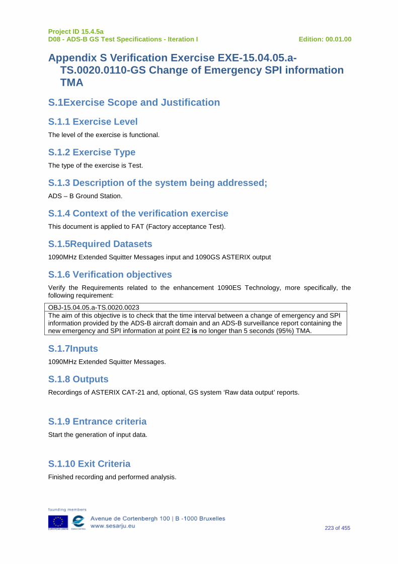
Project ID 15.4.5a D08 - ADS-B GS Test Specifications - Iteration I Edition: 00.01.00
223 of 455
Appendix S Verification Exercise EXE-15.04.05.a-TS.0020.0110-GS Change of Emergency SPI information TMA
S.1Exercise Scope and Justification
S.1.1 Exercise Level The level of the exercise is functional.
S.1.2 Exercise Type The type of the exercise is Test.
S.1.3 Description of the system being addressed; ADS – B Ground Station.
S.1.4 Context of the verification exercise This document is applied to FAT (Factory acceptance Test).
S.1.5Required Datasets 1090MHz Extended Squitter Messages input and 1090GS ASTERIX output
S.1.6 Verification objectives Verify the Requirements related to the enhancement 1090ES Technology, more specifically, the following requirement:
OBJ-15.04.05.a-TS.0020.0023 The aim of this objective is to check that the time interval between a change of emergency and SPI information provided by the ADS-B aircraft domain and an ADS-B surveillance report containing the new emergency and SPI information at point E2 is no longer than 5 seconds (95%) TMA.
S.1.7Inputs 1090MHz Extended Squitter Messages.
S.1.8 Outputs Recordings of ASTERIX CAT-21 and, optional, GS system ‘Raw data output’ reports.
S.1.9 Entrance criteria Start the generation of input data.
S.1.10 Exit Criteria Finished recording and performed analysis.
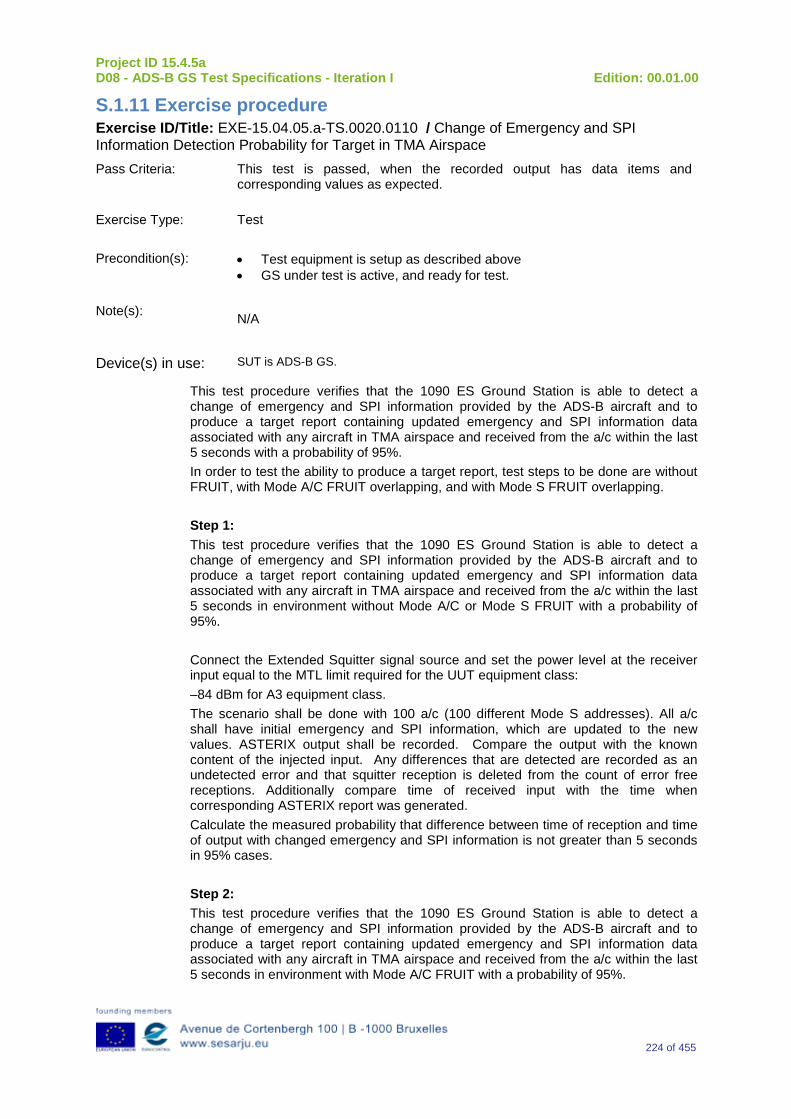
Project ID 15.4.5a D08 - ADS-B GS Test Specifications - Iteration I Edition: 00.01.00
224 of 455
S.1.11 Exercise procedure Exercise ID/Title: EXE-15.04.05.a-TS.0020.0110 / Change of Emergency and SPI Information Detection Probability for Target in TMA Airspace Pass Criteria: This test is passed, when the recorded output has data items and
corresponding values as expected.
Exercise Type: Test
Precondition(s): • Test equipment is setup as described above • GS under test is active, and ready for test.
Note(s): N/A
Device(s) in use: SUT is ADS-B GS.
This test procedure verifies that the 1090 ES Ground Station is able to detect a change of emergency and SPI information provided by the ADS-B aircraft and to produce a target report containing updated emergency and SPI information data associated with any aircraft in TMA airspace and received from the a/c within the last 5 seconds with a probability of 95%. In order to test the ability to produce a target report, test steps to be done are without FRUIT, with Mode A/C FRUIT overlapping, and with Mode S FRUIT overlapping. Step 1: This test procedure verifies that the 1090 ES Ground Station is able to detect a change of emergency and SPI information provided by the ADS-B aircraft and to produce a target report containing updated emergency and SPI information data associated with any aircraft in TMA airspace and received from the a/c within the last 5 seconds in environment without Mode A/C or Mode S FRUIT with a probability of 95%. Connect the Extended Squitter signal source and set the power level at the receiver input equal to the MTL limit required for the UUT equipment class: –84 dBm for A3 equipment class. The scenario shall be done with 100 a/c (100 different Mode S addresses). All a/c shall have initial emergency and SPI information, which are updated to the new values. ASTERIX output shall be recorded. Compare the output with the known content of the injected input. Any differences that are detected are recorded as an undetected error and that squitter reception is deleted from the count of error free receptions. Additionally compare time of received input with the time when corresponding ASTERIX report was generated. Calculate the measured probability that difference between time of reception and time of output with changed emergency and SPI information is not greater than 5 seconds in 95% cases. Step 2: This test procedure verifies that the 1090 ES Ground Station is able to detect a change of emergency and SPI information provided by the ADS-B aircraft and to produce a target report containing updated emergency and SPI information data associated with any aircraft in TMA airspace and received from the a/c within the last 5 seconds in environment with Mode A/C FRUIT with a probability of 95%.
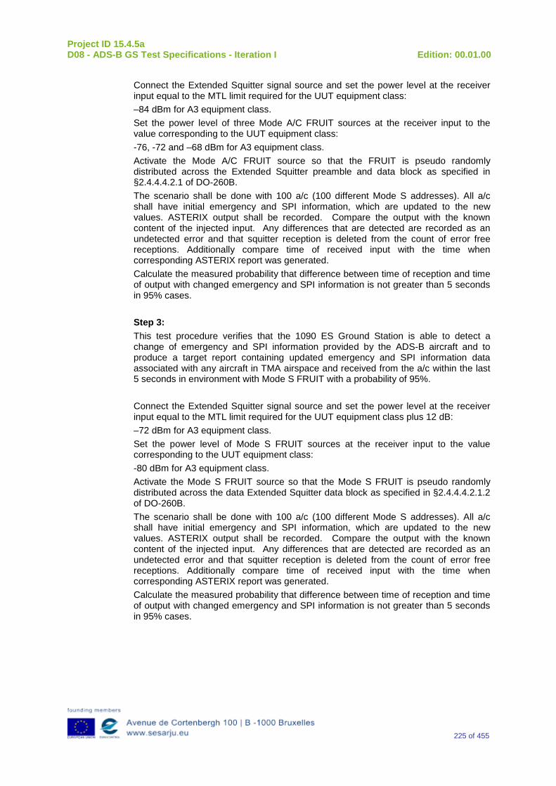
Project ID 15.4.5a D08 - ADS-B GS Test Specifications - Iteration I Edition: 00.01.00
225 of 455
Connect the Extended Squitter signal source and set the power level at the receiver input equal to the MTL limit required for the UUT equipment class: –84 dBm for A3 equipment class. Set the power level of three Mode A/C FRUIT sources at the receiver input to the value corresponding to the UUT equipment class: -76, -72 and –68 dBm for A3 equipment class. Activate the Mode A/C FRUIT source so that the FRUIT is pseudo randomly distributed across the Extended Squitter preamble and data block as specified in §2.4.4.4.2.1 of DO-260B. The scenario shall be done with 100 a/c (100 different Mode S addresses). All a/c shall have initial emergency and SPI information, which are updated to the new values. ASTERIX output shall be recorded. Compare the output with the known content of the injected input. Any differences that are detected are recorded as an undetected error and that squitter reception is deleted from the count of error free receptions. Additionally compare time of received input with the time when corresponding ASTERIX report was generated. Calculate the measured probability that difference between time of reception and time of output with changed emergency and SPI information is not greater than 5 seconds in 95% cases. Step 3: This test procedure verifies that the 1090 ES Ground Station is able to detect a change of emergency and SPI information provided by the ADS-B aircraft and to produce a target report containing updated emergency and SPI information data associated with any aircraft in TMA airspace and received from the a/c within the last 5 seconds in environment with Mode S FRUIT with a probability of 95%. Connect the Extended Squitter signal source and set the power level at the receiver input equal to the MTL limit required for the UUT equipment class plus 12 dB: –72 dBm for A3 equipment class. Set the power level of Mode S FRUIT sources at the receiver input to the value corresponding to the UUT equipment class: -80 dBm for A3 equipment class. Activate the Mode S FRUIT source so that the Mode S FRUIT is pseudo randomly distributed across the data Extended Squitter data block as specified in §2.4.4.4.2.1.2 of DO-260B. The scenario shall be done with 100 a/c (100 different Mode S addresses). All a/c shall have initial emergency and SPI information, which are updated to the new values. ASTERIX output shall be recorded. Compare the output with the known content of the injected input. Any differences that are detected are recorded as an undetected error and that squitter reception is deleted from the count of error free receptions. Additionally compare time of received input with the time when corresponding ASTERIX report was generated. Calculate the measured probability that difference between time of reception and time of output with changed emergency and SPI information is not greater than 5 seconds in 95% cases.
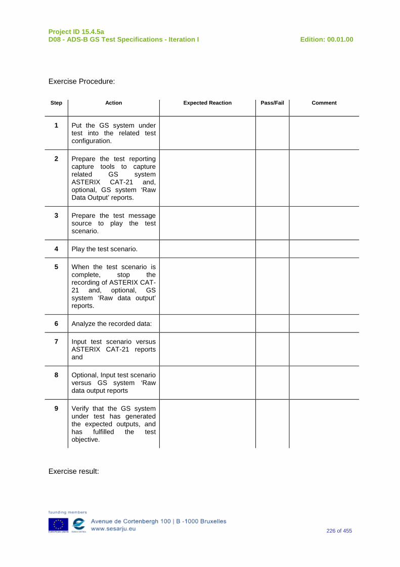
Project ID 15.4.5a D08 - ADS-B GS Test Specifications - Iteration I Edition: 00.01.00
226 of 455
Exercise Procedure:
Step Action Expected Reaction Pass/Fail Comment
1 Put the GS system under test into the related test configuration.
2 Prepare the test reporting capture tools to capture related GS system ASTERIX CAT-21 and, optional, GS system ‘Raw Data Output’ reports.
3 Prepare the test message source to play the test scenario.
4 Play the test scenario.
5 When the test scenario is complete, stop the recording of ASTERIX CAT-21 and, optional, GS system ‘Raw data output’ reports.
6 Analyze the recorded data:
7 Input test scenario versus ASTERIX CAT-21 reports and
8 Optional, Input test scenario versus GS system ‘Raw data output reports
9 Verify that the GS system under test has generated the expected outputs, and has fulfilled the test objective.
Exercise result:

Project ID 15.4.5a D08 - ADS-B GS Test Specifications - Iteration I Edition: 00.01.00
227 of 455
Pass Fail Done By (Name, Organisation)
Configuration(s) during the exercise Date
Table 24: Verification Exercise Result
S.1.12 Verification SUT requirements N/A
S.1.13 Exercise Tool, Verification Technique and/or Platform
ADS-BGround Station
Power
ASTERIX(and Raw Data)
Recording
UTC Time Reference
RF Source(Message Generator)
The Exercise will be verified in a platform with the following foreseen tools/equipment:
-Ground Station ADS–B
-Message Generator
-ASTERIX (and Raw Data) Recording Tool
-Power Source
-UTC time Reference.
The Item reported above will be capable to perform the functionalities reported below.
Ground Station ADS-B
The primary function of the 1090 GS is to receive 1090 MHz Mode S Extended Squitter messages, extract the data contained therein, and create appropriated ASTERIX Category 21 and 23 Reports (and optionally, Raw Data).
Message Generator
The Messages Generator will be capable to generate the data coming from the Remote System (ADS–B Ground Station or 1090 Receiver) like:
•Target data stream with inside the information extracted by the ADS–B message (ASTERIX CAT 21 in the case of Ground Station or Raw Data in the case that remote system is a 1090 MHz Receiver).
•Operational Data Stream with inside the Remote System’s Operational Status Information (ASTERIX CAT 23 in the case of Ground Station or Raw Data in the case that remote system is a 1090 MHz Receiver).
UTC Time Reference
The UTC Time reference is the solution adopted in the Test Scenario in order to provide the Synchronization in the Ground Station by UTC Time.
Project ID 15.4.5a D08 - ADS-B GS Test Specifications - Iteration I Edition: 00.01.00
228 of 455
ASTERIX Recording Equipment
The ASTERIX recording equipment will be capable to record all ASTERIX reports sent from the 1090 ES Ground Station.
S.1.14 Verification Platform needs See section 3.5 Verification Platform Needs.
S.1.15 Platform Configuration N/A
S.1.16 Configuration(s) Identification of the Verification Platform N/A
S.1.17 Links to other Verification Exercises N/A
S.1.18 Representatively level/ limitations N/A
S.2 Exercises Planning and management
S.2.1 Activities
S.2.1.1 Preparatory activities Setup the tools/equipment listed in 3.5 and S.1.13 in order to meet the Test Preconditions.
S.2.1.2 Execution activities Play the scenario generating in the input the desired messages and record the relevant ASTERIX (and Raw Data) output.
S.2.1.3 Post execution activities The post execution activities will be mainly focused on the analysis of recorded ASTERIX reports (and Raw Data reports). The analysis shall be done in order to verify the right information propagation as requested in each Test Scenario.
S.2.2 Human Resources. N/A
S.2.3 Responsibilities in the exercise N/A
S.2.4 Training N/A

Project ID 15.4.5a D08 - ADS-B GS Test Specifications - Iteration I Edition: 00.01.00
229 of 455
S.2.5 Time planning N/A
S.2.6 Risks. N/A
S.2.7 Errors and Observation handling N/A
S.3 Analysis Specification
S.3.1 Data collection methods The data collection during the test will be Qualitative. In fact after test execution the analysis of ASTERIX Data will be performed verifying that the values reported in the output are in line with the values generated in the input.
S.3.2Analysis method N/A
S.3.3 Data logging requirements The data logging requirements for this scenario will foresee at least ASTERIX CAT 21 items.
Project ID 15.4.5a D08 - ADS-B GS Test Specifications - Iteration I Edition: 00.01.00
230 of 455
Appendix T Verification Exercise EXE-15.04.05.a-TS.0030.0 10-GS Integration with WAM
T.1Exercise Scope and Justification
T.1.1 Exercise Level The level of the exercise is functional.
T.1.2 Exercise Type The type of this exercise is Test.
T.1.3 Description of the system being addressed; ADS – B Ground Station.
T.1.4 Context of the verification exercise This document is applied to FAT (Factory Acceptance Test).
T.1.5 Required Datasets The Datasets foreseen for this exercise are:
ADS –B data in the input of the Ground Station.
ASTERIX report CAT20 for the WAM System.
ASTERIX report CAT19 for the WAM System.
T.1.6 Verification objectives Verify the Requirements related to the enhancement of ADS-B/WAM Integration.
OBJ-15.04.05.a-TS.0030.0001 The aim of this objective is to check that the ADS-B Ground Surveillance Domain is capable to receive output from a WAM system in ASTERIX CAT 020 version 1.7.
OBJ-15.04.05.a-TS.0030.0002 The aim of this objective is to check that the ADS-B Ground Surveillance Domain processes and decodes received WAM data in ASTERIX CAT020 version 1.7. The following minimum set of data item should be decoded: • Aircraft Horizontal Position – Latitude and Longitude • Pressure altitude • Aircraft Identity (Mode 3A, Mode-S Address, Aircraft-Id) and Emergency Indicators • Time of Applicability
OBJ-15.04.05.a-TS.0030.0003 The aim of this objective is to check that the ADS-B Ground Surveillance Domain is capable of receive WAM system status messages in ASTERIX CAT 019 version 1.2.
Project ID 15.4.5a D08 - ADS-B GS Test Specifications - Iteration I Edition: 00.01.00
231 of 455
OBJ-15.04.05.a-TS.0030.0004 The aim of this objective is to check that the, ADS-B Ground Surveillance Domain processes and decode received WAM data in ASTERIX CAT019 version 1.2. The following minimum set of data item needs to be decoded: • Time of Applicability • System Status
OBJ-15.04.05.a-TS.0030.0005 The aim of this objective is to check that the ADS-B Ground Surveillance Domain uses the WAM System Status received by ASTERIX CAT019 as a criterion for the enabling of the ADS-B validity check.
OBJ-15.04.05.a-TS.0030.0006 The aim of this objective is to check that the ADS-B Ground Surveillance Domain correlates ADS-B reports received through 1090ES with reports received from a WAM System in ASTERIX CAT020 version 1.7.
OBJ-15.04.05.a-TS.0030.0007 The aim of this objective is to check that the ADS-B Ground Surveillance Domain verifies the validity of ADS-B reports by comparing ADS-B position data with position data of correlated WAM reports.
OBJ-15.04.05.a-TS.0030.0008 The aim of this objective is to check that the validation result (positive/negative) shall be reported in the CAT021 ADS-B report
T.1.7 Inputs The foreseen inputs for this exercise are:
Message in the Ground Station Input.
ASTERIX report CAT20 for the WAM System
ASTERIX report CAT19 for the WAM System.
T.1.8 Outputs ASTERIX Report Recording
T.1.9 Entrance criteria Start the generation of input data.
T.1.10 Exit Criteria The Test will finish after the generation and injection of input data and recording of output data.
T.1.11 Exercise procedure Exercise ID/Title: EXE-15.04.05.a-TS.0030.0 10 / Integration with WAM
Pass Criteria: The test is passed if the conditions described in the different scenarios are
Project ID 15.4.5a D08 - ADS-B GS Test Specifications - Iteration I Edition: 00.01.00
232 of 455
verified.
Exercise Type: Test Precondition(s): The test equipment setup will be in line with that described in Section A.1.13
(see below). The following Scenarios will be simulated: Scenario 1: It will be simulated that the Time Out for ASTERIX CAT 19 reception expires and as long as this condition persists the relevant information are propagated in the output of the Ground Station by means :
•ASTERIX CAT 23
•ASTERIX CAT 21 with the ADS – B report marked as NOT VALIDATED.
In this Scenario it will be simulated the following input:
oADS – B input messages in the Ground Station referring to an aircraft with a specific 24 – bit Address.
oASTERIX CAT20 reports in input of Ground Station referring to an aircraft with the same 24 bits Address used for the ADS – B input messages.
oNo ASTERIX CAT19. The ADS – B messages and ASTERIX CAT20 will be set (e.g. number , Latitude , Longitude, Time of applicability) in order to perform the ADS-B/WAM check. Scenario 2: In this scenario it will be verified that ADS –B /WAM Validity Check is performed only if the field I019/550 ( NOGO) is set to 00. In this Scenario it will be simulated the following input:
oADS – B input messages in the Ground Station referring to an aircraft with a specific 24 – bit Address.
oASTERIX CAT20 reports in input of Ground Station referring to an aircraft with the same 24 bits Address used for the ADS – B input messages.
oASTERIX CAT19 with the following set in the item: I019/550 ( NOGO) is set to 00 or 01.
The ADS – B messages and ASTERIX CAT20 will be set (e.g. number , Latitude , Longitude, Time of applicability) in order to verify that the ADS-B/WAM check is passed with the relevant 1090 GS report marked as VALID in ASTERIX CAT 21 as long as the above test condition persists and to verify that ASTERIX CAT 023 is sent showing that WAM integration Validation is Active.
Project ID 15.4.5a D08 - ADS-B GS Test Specifications - Iteration I Edition: 00.01.00
233 of 455
Scenario 3: In this scenario it will be simulated that the information coming from ASTERIX CAT19 in the field I019/550 ( NOGO) is set to 11 10 or 01 with the ADS –B /WAM Validity Check not performed. In this Scenario it will be simulated the following input:
oADS – B input messages in the Ground Station referring to an aircraft with a specific 24 – bit Address.
oASTERIX CAT 20 reports in input of Ground Station referring to an aircraft with the same 24 bits Address used for the ADS – B input messages.
oASTERIX CAT 19 with the item I019/550 ( NOGO) set to 11 10 or 01.
The ADS – B messages and ASTERIX CAT20 will be set (e.g. number , Latitude , Longitude, Time of applicability) in order to perform the ADS-B/WAM check but the ADS – B report is marked as NOT VALIDATED in ASTERIX CAT 21 due to information coming from ASTERIX CAT19. In this case it will be verified that:
•The test is not performed with the ADS – B report marked as NOT VALIDATED over ASTERIX CAT 21 and WAM integration validation is not active over ASTERIX CAT23
Scenario 4: In This Scenario it will be simulated the following input:
•ADS – B input messages in the Ground Station referring to an aircraft with a specific 24 – bit Address.
•ASTERIX CAT 20 reports in input of Ground Station referring to an aircraft with the same 24 bits Address used for the ADS – B input messages.
•ASTERIX CAT 19 with the item I019/550 ( NOGO) set to 00. The messages ADS – B and ASTERIX CAT 20 will be set (e.g. number , Latitude , Longitude, Time of applicability) in order to verify that the ADS-B/WAM check is NOT passed with the relevant 1090 GS report marked as NOT VALID over ASTERIX CAT 21and to verify that ASTERIX CAT 023 is sent showing that WAM integration Validation is Active.
Note(s): Device(s) in use: Ground Station ADS – B
Project ID 15.4.5a D08 - ADS-B GS Test Specifications - Iteration I Edition: 00.01.00
234 of 455
Message Generator
ASTERIX Recording Tool
Power
UTC time Reference
Exercise Procedure: Step Action Expected Reaction Pass/Fail Comment
1 Put the 1090GS in the default configuration.
2 In the 1090 GS, activate the ADS-B/WAM check.
3 Set the parameter Time Out Parameter for ASTERIX 19 reception = XX seconds
4 Set the parameter ADS-B/WAM Threshold = ZZZ meters.
5 Prepare the report capture tool to capture ASTERIX reports
6 Prepare the message source to play the scenario.
7 For each scenario: Play the scenario. When the scenario is complete, stop recording ASTERIX reports Analyze the recorded data and verify that the conditions described above are met
Exercise result:
Pass Fail Done By (Name, Organisation)
Configuration(s) during the exercise Date
Table 25: Verification Exercise Result
T.1.12 Verification SUT requirements N/A
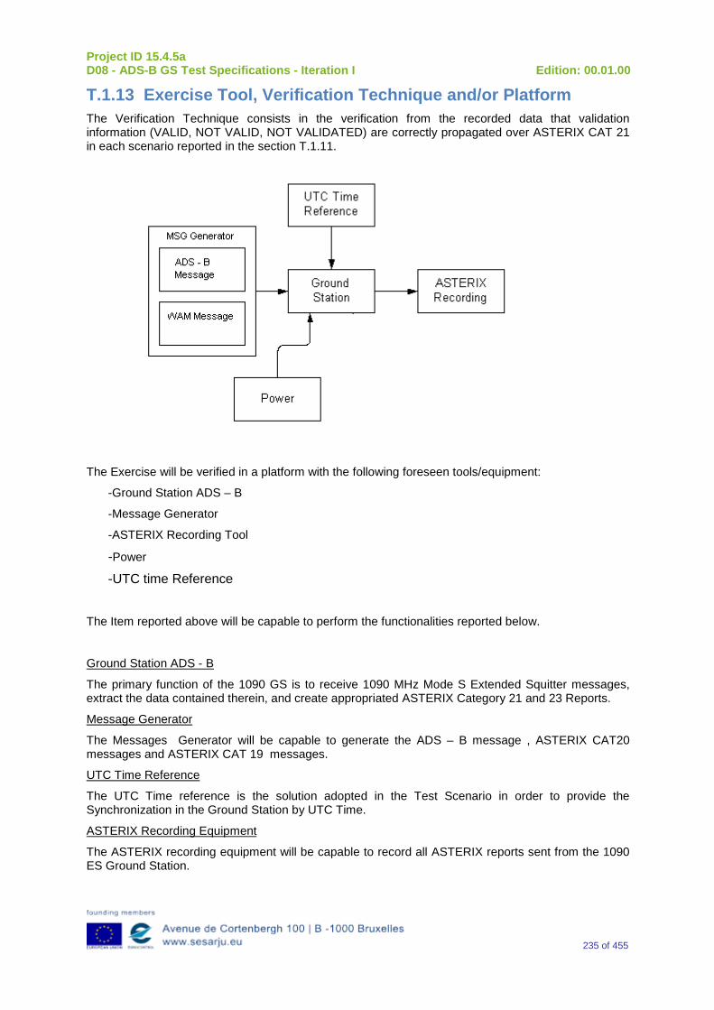
Project ID 15.4.5a D08 - ADS-B GS Test Specifications - Iteration I Edition: 00.01.00
235 of 455
T.1.13 Exercise Tool, Verification Technique and/or Platform The Verification Technique consists in the verification from the recorded data that validation information (VALID, NOT VALID, NOT VALIDATED) are correctly propagated over ASTERIX CAT 21 in each scenario reported in the section T.1.11.
The Exercise will be verified in a platform with the following foreseen tools/equipment:
-Ground Station ADS – B
-Message Generator
-ASTERIX Recording Tool
-Power
-UTC time Reference
The Item reported above will be capable to perform the functionalities reported below.
Ground Station ADS - B
The primary function of the 1090 GS is to receive 1090 MHz Mode S Extended Squitter messages, extract the data contained therein, and create appropriated ASTERIX Category 21 and 23 Reports.
Message Generator
The Messages Generator will be capable to generate the ADS – B message , ASTERIX CAT20 messages and ASTERIX CAT 19 messages.
UTC Time Reference
The UTC Time reference is the solution adopted in the Test Scenario in order to provide the Synchronization in the Ground Station by UTC Time.
ASTERIX Recording Equipment
The ASTERIX recording equipment will be capable to record all ASTERIX reports sent from the 1090 ES Ground Station.
Project ID 15.4.5a D08 - ADS-B GS Test Specifications - Iteration I Edition: 00.01.00
236 of 455
T.1.14 Verification Platform needs See section 3.5 Verification Platform Needs.
T.1.15 Platform Configuration N/A
T.1.16 Configuration(s) Identification of the Verification Platform N/A
T.1.17 Links to other Verification Exercises N/A
T.1.18 Representatively level/ limitations N/A
T.2 Exercises Planning and management
T.2.1 Activities
T.2.1.1 Preparatory activities Setup the tools/equipment listed in 3.5 and T.1.13 in order to meet the Test Preconditions
T.2.1.2 Execution activities Play the scenario generating in the input the Desired messages and record the relevant ASTERIX output.
T.2.1.3 Post execution activities The post execution activities will be mainly focused on the analysis of recorded ASTERIX reports during the application of each Scenario above. The Recorded ASTERIX reports will be analyzed in order to verify the right information propagation as requested in each Test Scenario.
T.2.2 Human Resources. N/A
T.2.3 Responsibilities in the exercise N/A
T.2.4 Training N/A
T.2.5 Time planning N/A
T.2.6 Risks. N/A
Project ID 15.4.5a D08 - ADS-B GS Test Specifications - Iteration I Edition: 00.01.00
237 of 455
T.2.7 Errors and Observation handling N/A
T.3 Analysis Specification
T.3.1 Data collection methods The data’s collection during the test will be Qualitative.
T.3.2 Analysis method N/A
T.3.3 Data logging requirements The data logging requirements for this scenario will foresee at least ASTERIX CAT 21 and ASTERIX CAT 23 item.
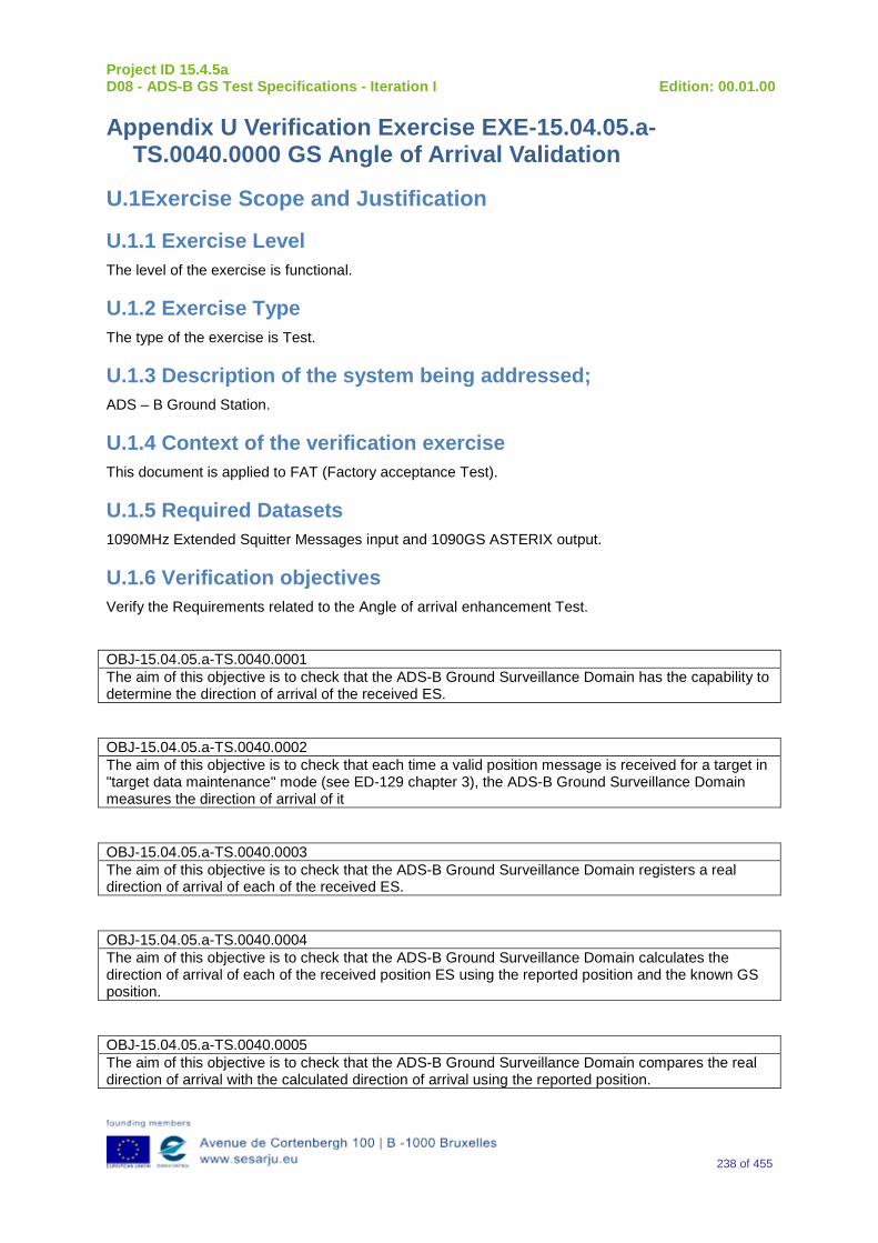
Project ID 15.4.5a D08 - ADS-B GS Test Specifications - Iteration I Edition: 00.01.00
238 of 455
Appendix U Verification Exercise EXE-15.04.05.a-TS.0040.0000 GS Angle of Arrival Validation
U.1Exercise Scope and Justification
U.1.1 Exercise Level The level of the exercise is functional.
U.1.2 Exercise Type The type of the exercise is Test.
U.1.3 Description of the system being addressed; ADS – B Ground Station.
U.1.4 Context of the verification exercise This document is applied to FAT (Factory acceptance Test).
U.1.5 Required Datasets 1090MHz Extended Squitter Messages input and 1090GS ASTERIX output.
U.1.6 Verification objectives Verify the Requirements related to the Angle of arrival enhancement Test.
OBJ-15.04.05.a-TS.0040.0001 The aim of this objective is to check that the ADS-B Ground Surveillance Domain has the capability to determine the direction of arrival of the received ES.
OBJ-15.04.05.a-TS.0040.0002 The aim of this objective is to check that each time a valid position message is received for a target in "target data maintenance" mode (see ED-129 chapter 3), the ADS-B Ground Surveillance Domain measures the direction of arrival of it
OBJ-15.04.05.a-TS.0040.0003 The aim of this objective is to check that the ADS-B Ground Surveillance Domain registers a real direction of arrival of each of the received ES.
OBJ-15.04.05.a-TS.0040.0004 The aim of this objective is to check that the ADS-B Ground Surveillance Domain calculates the direction of arrival of each of the received position ES using the reported position and the known GS position.
OBJ-15.04.05.a-TS.0040.0005 The aim of this objective is to check that the ADS-B Ground Surveillance Domain compares the real direction of arrival with the calculated direction of arrival using the reported position.
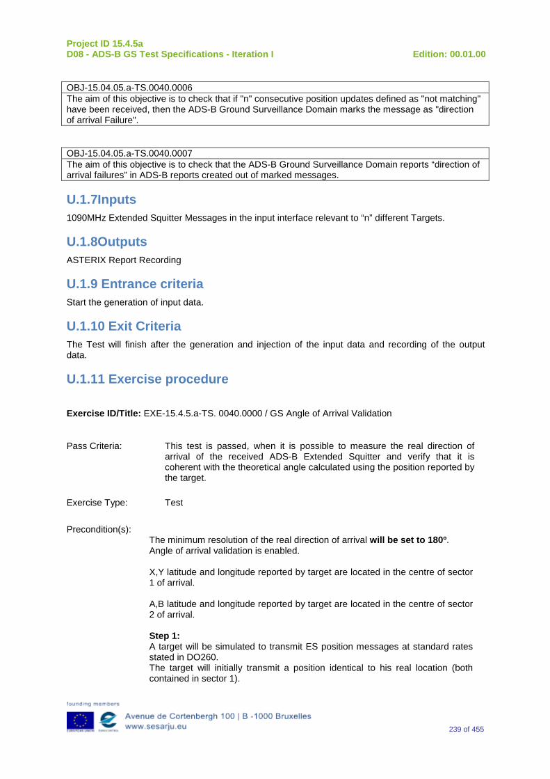
Project ID 15.4.5a D08 - ADS-B GS Test Specifications - Iteration I Edition: 00.01.00
239 of 455
OBJ-15.04.05.a-TS.0040.0006 The aim of this objective is to check that if "n" consecutive position updates defined as "not matching" have been received, then the ADS-B Ground Surveillance Domain marks the message as "direction of arrival Failure".
OBJ-15.04.05.a-TS.0040.0007 The aim of this objective is to check that the ADS-B Ground Surveillance Domain reports “direction of arrival failures” in ADS-B reports created out of marked messages.
U.1.7Inputs 1090MHz Extended Squitter Messages in the input interface relevant to “n” different Targets.
U.1.8Outputs ASTERIX Report Recording
U.1.9 Entrance criteria Start the generation of input data.
U.1.10 Exit Criteria The Test will finish after the generation and injection of the input data and recording of the output data.
U.1.11 Exercise procedure
Exercise ID/Title: EXE-15.4.5.a-TS. 0040.0000 / GS Angle of Arrival Validation
Pass Criteria: This test is passed, when it is possible to measure the real direction of arrival of the received ADS-B Extended Squitter and verify that it is coherent with the theoretical angle calculated using the position reported by the target.
Exercise Type: Test
Precondition(s): The minimum resolution of the real direction of arrival will be set to 180º. Angle of arrival validation is enabled. X,Y latitude and longitude reported by target are located in the centre of sector 1 of arrival. A,B latitude and longitude reported by target are located in the centre of sector 2 of arrival. Step 1: A target will be simulated to transmit ES position messages at standard rates stated in DO260. The target will initially transmit a position identical to his real location (both contained in sector 1).
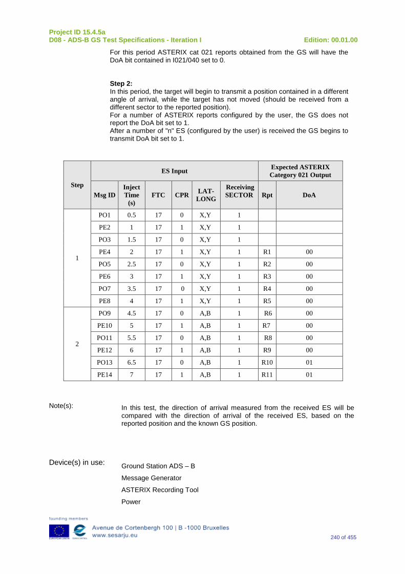
Project ID 15.4.5a D08 - ADS-B GS Test Specifications - Iteration I Edition: 00.01.00
240 of 455
For this period ASTERIX cat 021 reports obtained from the GS will have the DoA bit contained in I021/040 set to 0. Step 2: In this period, the target will begin to transmit a position contained in a different angle of arrival, while the target has not moved (should be received from a different sector to the reported position). For a number of ASTERIX reports configured by the user, the GS does not report the DoA bit set to 1. After a number of "n" ES (configured by the user) is received the GS begins to transmit DoA bit set to 1.
Step
ES Input Expected ASTERIX Category 021 Output
Msg ID Inject Time
(s) FTC CPR LAT-
LONG
Receiving SECTOR Rpt DoA
1
PO1 0.5 17 0 X,Y 1
PE2 1 17 1 X,Y 1
PO3 1.5 17 0 X,Y 1
PE4 2 17 1 X,Y 1 R1 00
PO5 2.5 17 0 X,Y 1 R2 00
PE6 3 17 1 X,Y 1 R3 00
PO7 3.5 17 0 X,Y 1 R4 00
PE8 4 17 1 X,Y 1 R5 00
2
PO9 4.5 17 0 A,B 1 R6 00
PE10 5 17 1 A,B 1 R7 00
PO11 5.5 17 0 A,B 1 R8 00
PE12 6 17 1 A,B 1 R9 00
PO13 6.5 17 0 A,B 1 R10 01
PE14 7 17 1 A,B 1 R11 01
Note(s): In this test, the direction of arrival measured from the received ES will be compared with the direction of arrival of the received ES, based on the reported position and the known GS position.
Device(s) in use: Ground Station ADS – B
Message Generator
ASTERIX Recording Tool
Power
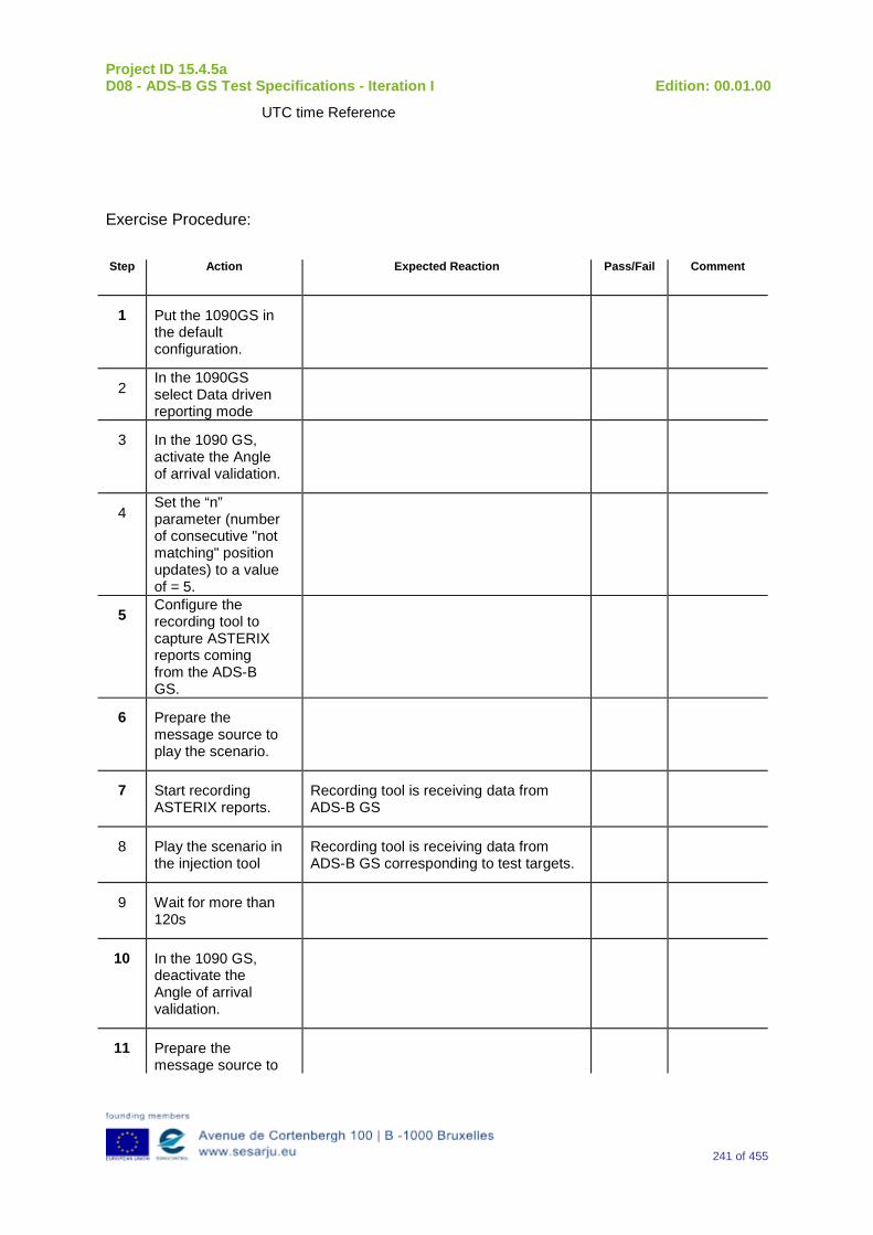
Project ID 15.4.5a D08 - ADS-B GS Test Specifications - Iteration I Edition: 00.01.00
241 of 455
UTC time Reference
Exercise Procedure:
Step Action Expected Reaction Pass/Fail Comment
1 Put the 1090GS in the default configuration.
2 In the 1090GS select Data driven reporting mode
3 In the 1090 GS, activate the Angle of arrival validation.
4 Set the “n” parameter (number of consecutive "not matching" position updates) to a value of = 5.
5 Configure the recording tool to capture ASTERIX reports coming from the ADS-B GS.
6 Prepare the message source to play the scenario.
7 Start recording ASTERIX reports.
Recording tool is receiving data from ADS-B GS
8 Play the scenario in the injection tool
Recording tool is receiving data from ADS-B GS corresponding to test targets.
9 Wait for more than 120s
10 In the 1090 GS, deactivate the Angle of arrival validation.
11 Prepare the message source to
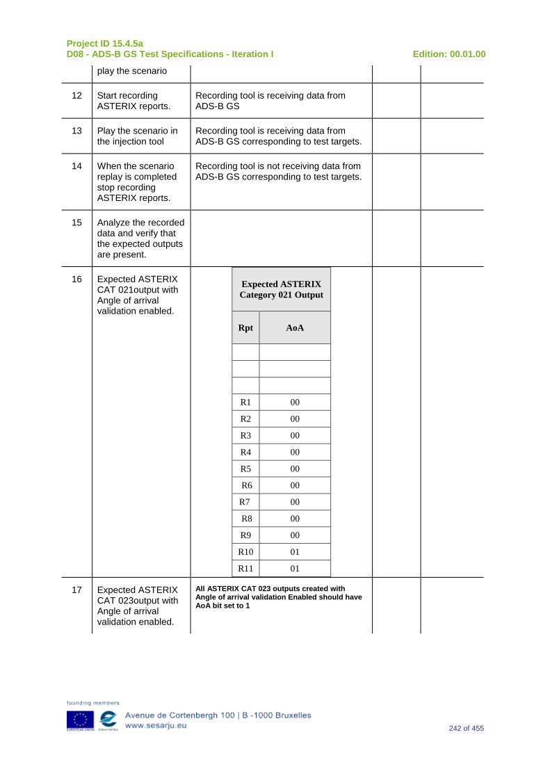
Project ID 15.4.5a D08 - ADS-B GS Test Specifications - Iteration I Edition: 00.01.00
242 of 455
play the scenario
12 Start recording ASTERIX reports.
Recording tool is receiving data from ADS-B GS
13 Play the scenario in the injection tool
Recording tool is receiving data from ADS-B GS corresponding to test targets.
14 When the scenario replay is completed stop recording ASTERIX reports.
Recording tool is not receiving data from ADS-B GS corresponding to test targets.
15 Analyze the recorded data and verify that the expected outputs are present.
16 Expected ASTERIX CAT 021output with Angle of arrival validation enabled.
Expected ASTERIX Category 021 Output
Rpt AoA
R1 00
R2 00
R3 00
R4 00
R5 00
R6 00
R7 00
R8 00
R9 00
R10 01
R11 01
17 Expected ASTERIX CAT 023output with Angle of arrival validation enabled.
All ASTERIX CAT 023 outputs created with Angle of arrival validation Enabled should have AoA bit set to 1
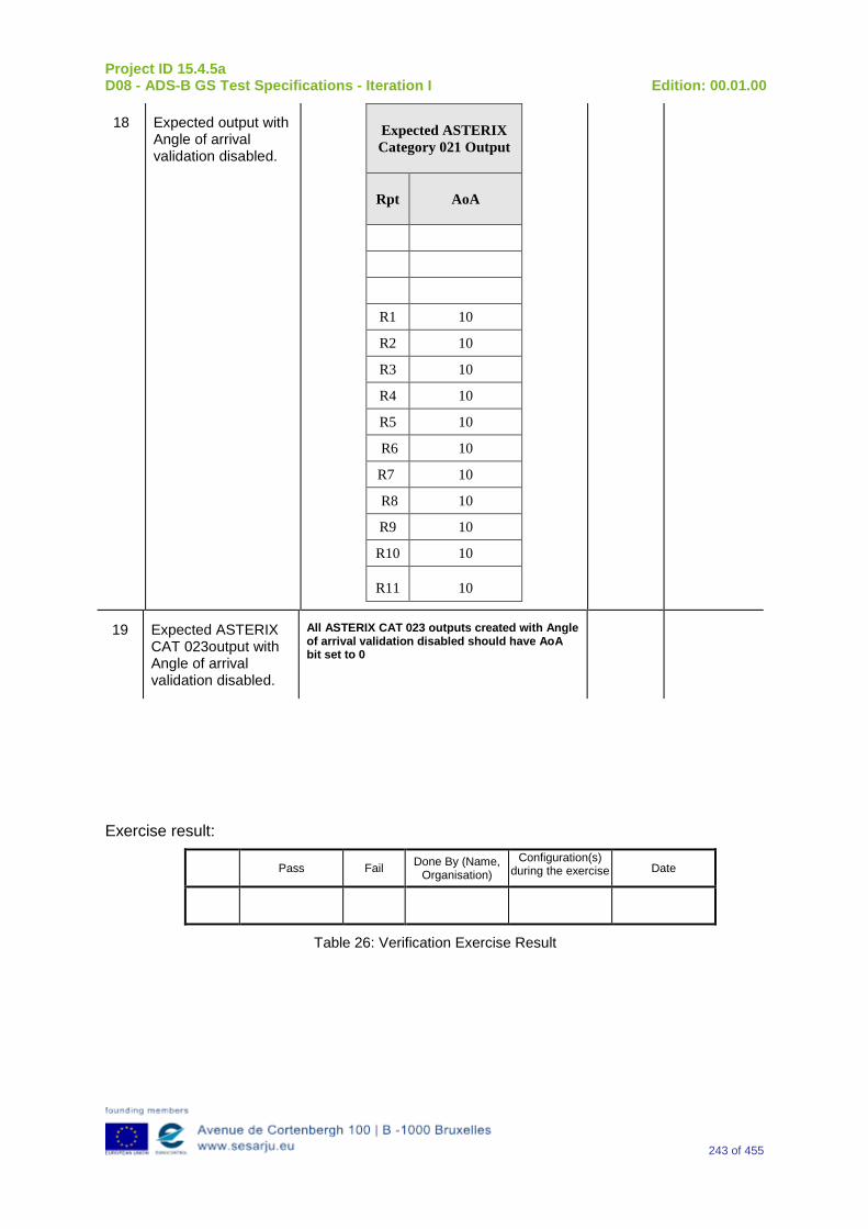
Project ID 15.4.5a D08 - ADS-B GS Test Specifications - Iteration I Edition: 00.01.00
243 of 455
18 Expected output with Angle of arrival validation disabled.
Expected ASTERIX Category 021 Output
Rpt AoA
R1 10
R2 10
R3 10
R4 10
R5 10
R6 10
R7 10
R8 10
R9 10
R10 10
R11 10
19 Expected ASTERIX CAT 023output with Angle of arrival validation disabled.
All ASTERIX CAT 023 outputs created with Angle of arrival validation disabled should have AoA bit set to 0
Exercise result:
Pass Fail Done By (Name, Organisation)
Configuration(s) during the exercise Date
Table 26: Verification Exercise Result
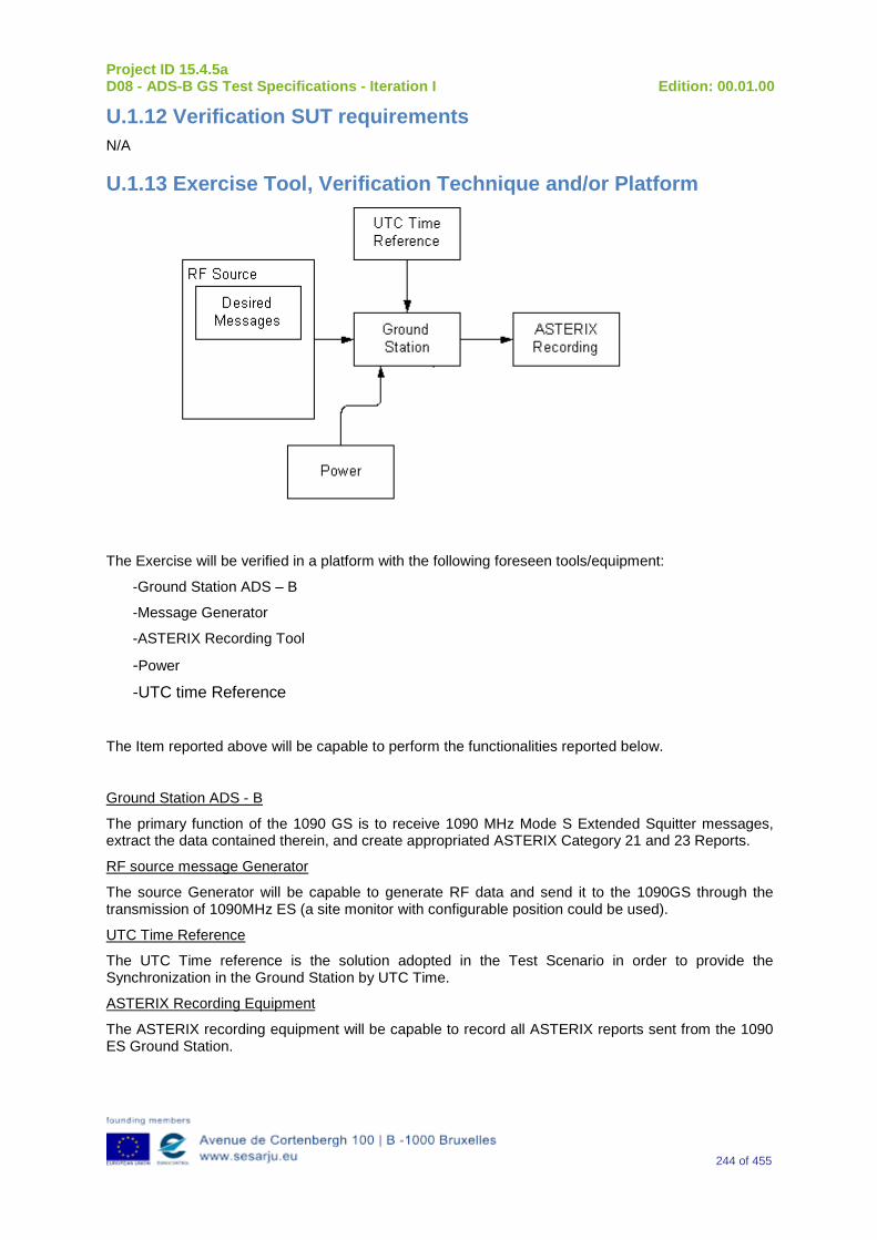
Project ID 15.4.5a D08 - ADS-B GS Test Specifications - Iteration I Edition: 00.01.00
244 of 455
U.1.12 Verification SUT requirements N/A
U.1.13 Exercise Tool, Verification Technique and/or Platform
The Exercise will be verified in a platform with the following foreseen tools/equipment:
-Ground Station ADS – B
-Message Generator
-ASTERIX Recording Tool
-Power -UTC time Reference
The Item reported above will be capable to perform the functionalities reported below.
Ground Station ADS - B
The primary function of the 1090 GS is to receive 1090 MHz Mode S Extended Squitter messages, extract the data contained therein, and create appropriated ASTERIX Category 21 and 23 Reports.
RF source message Generator
The source Generator will be capable to generate RF data and send it to the 1090GS through the transmission of 1090MHz ES (a site monitor with configurable position could be used).
UTC Time Reference
The UTC Time reference is the solution adopted in the Test Scenario in order to provide the Synchronization in the Ground Station by UTC Time.
ASTERIX Recording Equipment
The ASTERIX recording equipment will be capable to record all ASTERIX reports sent from the 1090 ES Ground Station.
Project ID 15.4.5a D08 - ADS-B GS Test Specifications - Iteration I Edition: 00.01.00
245 of 455
U.1.14 Verification Platform needs See section 3.5 Verification Platform Needs.
U.1.15 Platform Configuration N/A
U.1.16 Configuration(s) Identification of the Verification Platform N/A
U.1.17 Links to other Verification Exercises N/A
U.1.18 Representatively level/ limitations N/A
U.2 Exercises Planning and management
U.2.1 Activities N/A
U.2.1.1 Preparatory activities Setup the tools/equipment listed in 3.5 and U.1.13 in order to meet the Test Preconditions
U.2.1.2 Execution activities Play the scenario generating in the input the desired messages and record the relevant ASTERIX output.
U.2.1.3 Post execution activities The post execution activities will be mainly focused on the analysis of recorded ASTERIX report during the application of each Scenario above. The Recorded ASTERIX report will be analyzed in order to verify the right information propagation as requested in each Test Scenario.
U.2.2 Human Resources. N/A
U.2.3 Responsibilities in the exercise N/A
U.2.4 Training N/A
U.2.5 Time planning N/A
Project ID 15.4.5a D08 - ADS-B GS Test Specifications - Iteration I Edition: 00.01.00
246 of 455
U.2.6 Risks N/A
U.2.7 Errors and Observation handling N/A
U.3 Analysis Specification
U.3.1 Data collection methods The data’s collection during the test will be Qualitative.
U.3.2 Analysis method N/A
U.3.3 Data logging requirements The data logging requirements for this scenario will foresee at least ASTERIX CAT 21 and ASTERIX CAT 23 item.
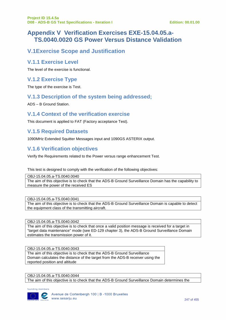
Project ID 15.4.5a D08 - ADS-B GS Test Specifications - Iteration I Edition: 00.01.00
247 of 455
Appendix V Verification Exercises EXE-15.04.05.a-TS.0040.0020 GS Power Versus Distance Validation
V.1Exercise Scope and Justification
V.1.1 Exercise Level The level of the exercise is functional.
V.1.2 Exercise Type The type of the exercise is Test.
V.1.3 Description of the system being addressed; ADS – B Ground Station.
V.1.4 Context of the verification exercise This document is applied to FAT (Factory acceptance Test).
V.1.5 Required Datasets 1090MHz Extended Squitter Messages input and 1090GS ASTERIX output.
V.1.6 Verification objectives Verify the Requirements related to the Power versus range enhancement Test.
This test is designed to comply with the verification of the following objectives:
OBJ-15.04.05.a-TS.0040.0040 The aim of this objective is to check that the ADS-B Ground Surveillance Domain has the capability to measure the power of the received ES
OBJ-15.04.05.a-TS.0040.0041 The aim of this objective is to check that the ADS-B Ground Surveillance Domain is capable to detect the equipment class of the transmitting aircraft.
OBJ-15.04.05.a-TS.0040.0042 The aim of this objective is to check that once a valid position message is received for a target in "target data maintenance" mode (see ED-129 chapter 3), the ADS-B Ground Surveillance Domain estimates the transmission power of it.
OBJ-15.04.05.a-TS.0040.0043 The aim of this objective is to check that the ADS-B Ground Surveillance Domain calculates the distance of the target from the ADS-B receiver using the reported position and altitude
OBJ-15.04.05.a-TS.0040.0044 The aim of this objective is to check that the ADS-B Ground Surveillance Domain determines the
Project ID 15.4.5a D08 - ADS-B GS Test Specifications - Iteration I Edition: 00.01.00
248 of 455
approximate distance of each of the received ES using the measured power and equipment class. (see ED129 appendix F)
OBJ-15.04.05.a-TS.0040.0045 The aim of this objective is to check that the ADS-B Ground Surveillance Domain compares the distance obtained from the received position data with the distance calculated using measured power increments.
OBJ-15.04.05.a-TS.0040.0046 The aim of this objective is to check that "n" consecutive position updates for which the difference between the approximate distance and the reported distance is greater than "x" Nm have been received in "t" seconds, then the ADS-B Ground Surveillance Domain marks the message as "Power/Distance inconsistency".
OBJ-15.04.05.a-TS.0040.0047 The aim of this objective is to check that the ADS-B Ground Surveillance Domain reports “Power/Range inconsistency” in ADS-B reports created out of marked messages.
V.1.7Inputs 1090MHz Extended Squitter Messages in the input interface relevant to “n” different Targets.
V.1.8 Outputs Identify the deliverable generated to test compliance.
ASTERIX Report Recording.
V.1.9 Entrance criteria Start the generation of input data.
V.1.10 Exit Criteria The Test will finish after the generation and injection of the input data and recording of the output data.
V.1.11 Exercise procedure Exercise ID/Title: EXE-15.4.5.a-TS.0040.0020 / GS Power Versus Distance Validation
Pass Criteria: This test is passed, when it is possible to measure the power of the received ADS-B Extended Squitter and verify that it is coherent with the theoretical power calculated using the position reported by the target.
Project ID 15.4.5a D08 - ADS-B GS Test Specifications - Iteration I Edition: 00.01.00
249 of 455
Exercise Type: Test
Precondition(s): The scenario will include the next test targets:
Correct target1: Target 1 “A1” moves respect to sensor (approach or away) and transmits power related with the position reported. The injected power will be according to the distance between the target and the GS.
Incorrect target2: Target 2 “A2” moves respect to sensor (approach or away) and with transmitting power related with the position reported up to time "t1". After a later instant "t2", the target will maintain transmitting power at the value corresponding to "t2" until the end of the test. In the period of time between "t2" and the end of the test, in a certain moment, "t3" the target will be transmitting a constant power which should be marked as power-range failure. Incorrect target3: Target 3 “A3” moves respect to sensor (approach or away) and transmits power related with the position reported. The injected power will be at any moment outside the maximum and minimum values allowed for the different equipment classes according to the distance between the target and the GS.
Note(s):
Device(s) in use: ADSB GS
Exercise Procedure:
Step Action Expected Reaction Pass/Fail Comment
1 Put the 1090GS in the default configuration.
2 In the 1090GS select Data driven reporting mode
3 Configure the recording tool to capture ASTERIX reports coming from the ADS-B GS.
Project ID 15.4.5a D08 - ADS-B GS Test Specifications - Iteration I Edition: 00.01.00
250 of 455
4 Prepare the message source to play the scenario
5 Start recording ASTERIX reports.
Recording tool is receiving data from ADS-B GS
6 In the 1090 GS, activate the power versus range validation.
7 Play the scenario in the injection tool
Recording tool is receiving data from ADS-B GS corresponding to test targets.
8 When the scenario replay is completed stop recording ASTERIX reports.
Recording tool is not receiving data from ADS-B GS corresponding to test targets.
9 Analyze the recorded data and verify that the expected outputs are present.
AST reports for target 1 should have PrV bit set to 00 at any time.
10 Analyze the recorded data and verify that the expected outputs are present.
AST reports for target 2 created before t3 should have PrV bit set to 00.
11 Analyze the recorded data and verify that the expected outputs are present.
AST reports for target 2 created after t3 should have PrV bit set to 01.
12 Analyze the recorded data and verify that the expected outputs are present.
AST reports for target 3 created before t4 should have PrV bit set to 00.
13 Analyze the recorded data and verify that the expected outputs are present.
AST reports for target 3 created after t4 should have PrV bit set to 01.
14 Analyze the recorded data and verify that the expected outputs are present.
All ASTERIX CAT 023 outputs created with Power & range enabled should have PRV bit set to 1
15 Wait for at least 120s.
16 Configure the recording tool to capture ASTERIX reports coming from the ADS-B GS
17 In the 1090 GS, deactivate the power versus range
Project ID 15.4.5a D08 - ADS-B GS Test Specifications - Iteration I Edition: 00.01.00
251 of 455
validation.
18 Prepare the message source to play the scenario
19 Start recording ASTERIX reports.
Recording tool is receiving data from ADS-B GS
20 Play the scenario in the injection tool
Recording tool is receiving data from ADS-B GS corresponding to test targets.
21 When the scenario replay is completed stop recording ASTERIX reports.
Recording tool is not receiving data from ADS-B GS corresponding to test targets.
22 Analyze the recorded data and verify that the expected outputs are present.
AST reports for all targets should have PrV bit set to 10 at any time.
23 Analyze the recorded data and verify that the expected outputs are present.
All ASTERIX CAT 023 outputs created with Power & range disabledenabled should have PRV bit set to 1
Exercise result:
Pass Fail Done By (Name, Organisation)
Configuration(s) during the exercise Date
Table 27: Verification Exercise Result
V.1.12 Verification SUT requirements N/A
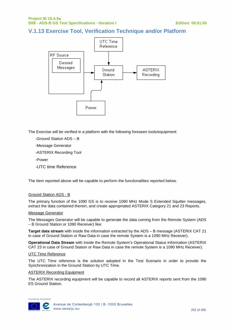
Project ID 15.4.5a D08 - ADS-B GS Test Specifications - Iteration I Edition: 00.01.00
252 of 455
V.1.13 Exercise Tool, Verification Technique and/or Platform
The Exercise will be verified in a platform with the following foreseen tools/equipment:
-Ground Station ADS – B
-Message Generator
-ASTERIX Recording Tool
-Power -UTC time Reference
The Item reported above will be capable to perform the functionalities reported below.
Ground Station ADS - B
The primary function of the 1090 GS is to receive 1090 MHz Mode S Extended Squitter messages, extract the data contained therein, and create appropriated ASTERIX Category 21 and 23 Reports.
Message Generator
The Messages Generator will be capable to generate the data coming from the Remote System (ADS – B Ground Station or 1090 Receiver) like:
Target data stream with inside the information extracted by the ADS – B message (ASTERIX CAT 21 in case of Ground Station or Raw Data in case the remote System is a 1090 MHz Receiver).
Operational Data Stream with inside the Remote System’s Operational Status Information (ASTERIX CAT 23 in case of Ground Station or Raw Data in case the remote System is a 1090 MHz Receiver).
UTC Time Reference
The UTC Time reference is the solution adopted in the Test Scenario in order to provide the Synchronization in the Ground Station by UTC Time.
ASTERIX Recording Equipment
The ASTERIX recording equipment will be capable to record all ASTERIX reports sent from the 1090 ES Ground Station.

Project ID 15.4.5a D08 - ADS-B GS Test Specifications - Iteration I Edition: 00.01.00
253 of 455
V.1.14 Verification Platform needs See section 3.5 Verification Platform Needs.
V.1.15 Platform Configuration N/A
V.1.16 Configuration(s) Identification of the Verification Platform N/A
V.1.17 Links to other Verification Exercises N/A
V.1.18 Representatively level/ limitations N/A
V.2 Exercises Planning and management
V.2.1 Activities N/A
V.2.1.1 Preparatory activities Setup the tools/equipment listed in 3.5 and V.1.13 in order to meet the Test Preconditions
V.2.1.2 Execution activities Play the scenario generating in the input the desired messages and record the relevant ASTERIX output.
V.2.1.3 Post execution activities The post execution activities will be mainly focused on the analysis of recorded ASTERIX report during the application of each Scenario above. The Recorded ASTERIX report will be analyzed in order to verify the right information propagation as requested in each Test Scenario.
V.2.2 Human Resources N/A
V.2.3 Responsibilities in the exercise N/A
V.2.4 Training N/A
V.2.5 Time planning N/A

Project ID 15.4.5a D08 - ADS-B GS Test Specifications - Iteration I Edition: 00.01.00
254 of 455
V.2.6 Risks N/A
V.2.7 Errors and Observation handling N/A
V.3 Analysis Specification
V.3.1 Data collection methods The data’s collection during the test will be Qualitative.
V.3.2 Analysis method N/A
V.3.3 Data logging requirements The data logging requirements for this scenario will foresee at least ASTERIX CAT 21 and ASTERIX CAT 23 item.
Project ID 15.4.5a D08 - ADS-B GS Test Specifications - Iteration I Edition: 00.01.00
255 of 455
Appendix W Verification Exercise EXE-15.04.05.a-TS.0040.0030 GS Time of Arrival versus Distance Validation
W.1Exercise Scope and Justification
W.1.1 Exercise Level The level of the exercise is functional.
W.1.2 Exercise Type The type of the exercise is Test.
W.1.3 Description of the system being addressed; ADS – B Ground Station.
W.1.4 Context of the verification exercise This document is applied to FAT (Factory Acceptance Test).
W.1.5 Required Datasets The Datasets foreseen for this exercise are:
N Target data stream coming from Remote System.
N Operational Status Data Stream coming from Remote System.
W.1.6 Verification objectives Verify the Requirements related to the TOA versus Distance enhancement Test.
OBJ-15.04.05.a-TS.0040.0030 The aim of this objective is to check that the ADS-B Ground Surveillance Domain is capable to determine the distance of a target from an ADS-B receiver by using the received horizontal position data, the received altitude data provided by several ADS-B receivers and the static receiver positions.
OBJ-15.04.05.a-TS.0040.0031 The aim of this objective is to check that the ADS-B Ground Surveillance Domain has a function elaborating the consistency of TOA versus calculated distance from an ADS-B receiver for multiple ADS-B receivers having received the same position squitter.
OBJ-15.04.05.a-TS.0040.0032 The aim of this objective is to check that the If "n" consecutive position updates for which the TOA/distance consistency check yields inconsistent, then the ADS-B Ground Surveillance Domain marks the message as "inconsistent TOA/distance".
Project ID 15.4.5a D08 - ADS-B GS Test Specifications - Iteration I Edition: 00.01.00
256 of 455
OBJ-15.04.05.a-TS.0040.0033 The aim of this objective is to check that the ADS-B Ground Surveillance Domain reports “inconsistent TOA/distance” in ADS-B reports created out of marked messages.
W.1.7 Inputs The Dataset foreseen for this exercise are:
N Target data stream coming from Remote System.
N Operational Status Data Stream coming from Remote System.
W.1.8 Outputs ASTERIX Report Recording
W.1.9 Entrance criteria Start the generation of input data.
W.1.10 Exit Criteria The Test will finish after the generation and injection of the input data and recording of the output data.
W.1.11 Exercise procedure Exercise ID/Title: EXE-15.04.05.a-TS.0040.0030-GS / Time of Arrival versus Distance Validation
Pass Criteria: The test is passed if the conditions described in the different scenarios, reported below, are verified.
Exercise Type: Test
Precondition(s): The following Scenarios will be simulated:
Scenario 1: It will be simulated that the Time Out for Target Data Streams coming from one Remote System expires.
The following inputs will be simulated:
N -1 Target Data Streams coming from Remote Systems
N Operational Status Data Streams coming from Remote Systems
In this case, after time out expiring, it will verify that the relevant information is propagated over ASTERIX CAT 23.
Project ID 15.4.5a D08 - ADS-B GS Test Specifications - Iteration I Edition: 00.01.00
257 of 455
Scenario 2
It will be simulated that the Time Out for System Operational Status Data Streams for one Remote System expires, with the corresponding Target Data Stream excluded by the Validity Check.
The following input will be simulated:
2 Target Data Streams coming from different Remote Systems
1 Operational Status Data Streams coming from one Remote Systems
In this case, it will be verified that:
After Time out expiration the relevant information is propagated over ASTERIX CAT 23.
Until the condition above persists, it is NOT possible to perform the TOA/DISTANCE Check with the 1090 GS report marked as NOT VALIDATED over ATX21 . The test above isn’t performed because the scenario foresees only 2 (two) remote system Target Data Streams and one will be excluded in the computation because the relevant Operational Status Data Stream is not available.
Scenario 3 In this Scenario it will be simulated that the operational status of one Remote System become not healthy and the relevant Target Data Stream will not be used in the TOA/DISTANCE Check.
The following input will be simulated:
2 Target Data Streams coming from remote systems
2 Operational Status Data Streams coming from remote systems with one Operational Data Streams set in order to simulate the transition between Healthy status to Not Healthy status in the Remote System.
Taking into account that we have in configuration only 2 (two) remote system it will be verified that:
Until the Status of both remote system are declared as healthy the TOA/DISTANCE Check will be performed and the 1090 GS report will be marked as in accordance with the setting of Target Data Streams in input.
After that Operational Status of one Remote System become NOT healthy the 1090 GS report is marked as NOT VALIDATED over ATX21. In fact the TOA/Distance Check isn’t performed because the scenario foresees only 2 (two) remote system Target Data Streams and one it will be excluded in the computation because the relevant Operational Status of the relevant Remote Systems become NOT healthily.
Project ID 15.4.5a D08 - ADS-B GS Test Specifications - Iteration I Edition: 00.01.00
258 of 455
Scenario 4
In this scenario it will be simulated the reception in the central Server function of N separate Target Data Streams and N Operational Status Data Streams with the Target Data Streams set in order to verify that the TOA/Distance Check conditions are passed.
The following inputs will be simulated:
N Target Data Streams coming from remote systems
N Operational Data Streams coming from remote systems
In this case, the check will be performed and the 1090 GS report will be marked as VALID over ASTERIX 21.
Scenario 5 In this scenario it will be simulated the reception in the central Server function of N separate Target Data Streams and N Operational Status Data Streams with the Target Data Streams set in order to verify that the TOA/Distance Check conditions are passed. In this case the Target Data Stream coming from Remote System it will be set in order to simulate a Target equidistant by two or more remote System.
The following inputs will be simulated:
N Target Data Streams coming from remote systems
N Operational Data Streams coming from remote systems
In this case, the check will be performed and the 1090 GS report will be marked as VALID over ASTERIX 21.
Scenario 6 In this scenario it will be simulated the reception in the central Server function of N separate Target Data Streams and N Operational Status Data Streams with the Target Data Streams set in order to verify that the TOA/Distance Check conditions are NOT passed.
The following inputs will be simulated:
Project ID 15.4.5a D08 - ADS-B GS Test Specifications - Iteration I Edition: 00.01.00
259 of 455
N Target Data Streams coming from remote systems
N Operational Data Streams coming from remote systems
In this case, the check will be performed and the 1090 GS report will be marked as NOT VALID over ASTERIX 21.
Note(s): In order to Perform the Exercise related to TOA versus Distance Validation are requested the following item in the System:
Central Server Function
n (with n >= 2) Remote Systems.
Each Remote System will be able to generate two different data stream:
Target data stream with inside the information extracted by the ADS – B message (ASTERIX CAT 21 in case of Ground Station or Raw Data in case the remote System is a 1090 MHz Receiver).
Operational Data Stream (ASTERIX CAT 23 in case of Ground Station or Raw Data referring to operational Status in case the remote System is a 1090 MHz Receiver).
Device(s) in use: Ground Station ADS – B
Message Generator
ASTERIX Recording Tool
Power
UTC time Reference.
Exercise Procedure:
Step Action Expected Reaction Pass/Fail Comment
1 Put the 1090GS in the default configuration.
2 In the 1090 GS, activate the TOA versus distance validation.
3 Set the parameter Time Out Parameter for Target Data Stream = XX seconds
4 Set the parameter Time Out
Project ID 15.4.5a D08 - ADS-B GS Test Specifications - Iteration I Edition: 00.01.00
260 of 455
Parameter for Operational Status Data Stream = YY seconds
5 Prepare the report capture tool to capture ASTERIX reports.
6 Prepare the message source to play the scenario
7 For each scenario:
-Play the scenario.
-When the scenario is complete, stop recording ASTERIX reports.
-Analyze the recorded data and verify that the conditions described above are met
Exercise result:
Pass Fail Done By (Name, Organisation)
Configuration(s) during the exercise Date
Table 28: Verification Exercise Result
W.1.12 Verification SUT requirements N/A
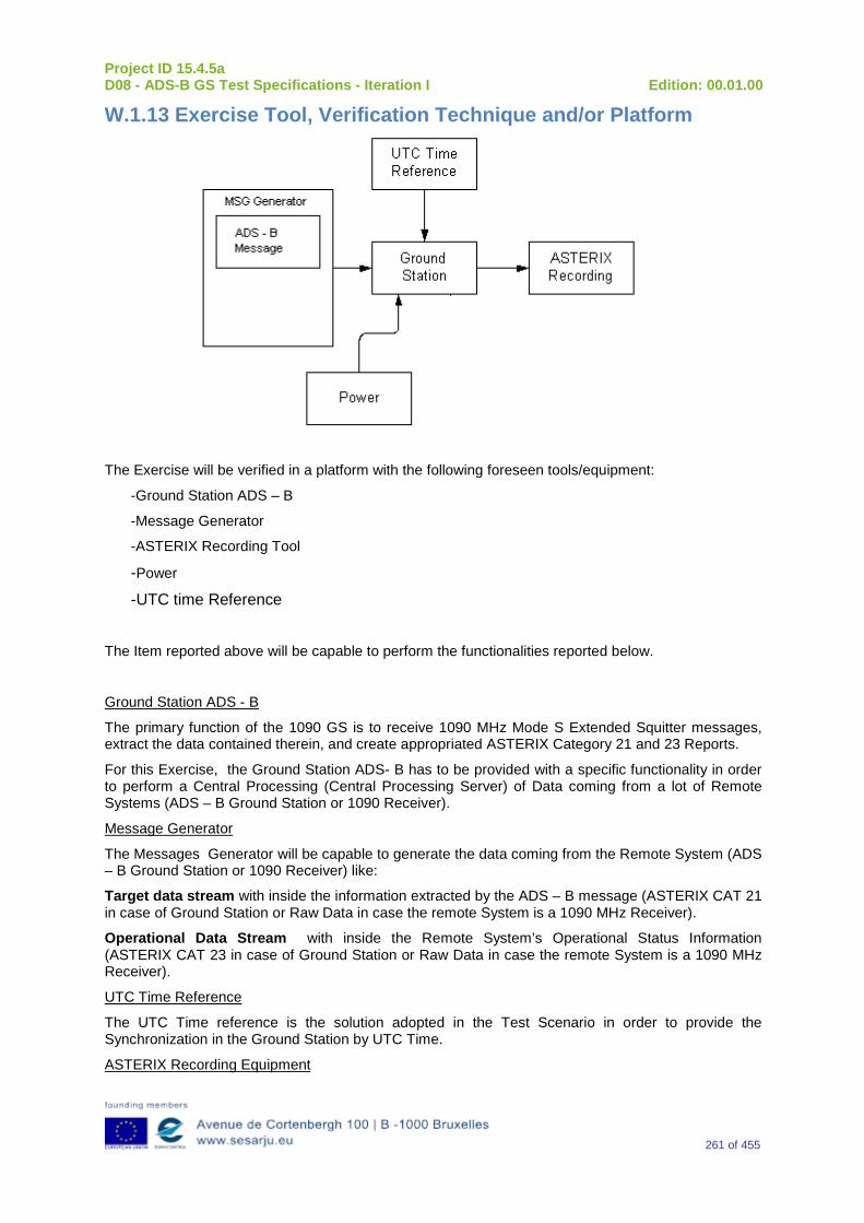
Project ID 15.4.5a D08 - ADS-B GS Test Specifications - Iteration I Edition: 00.01.00
261 of 455
W.1.13 Exercise Tool, Verification Technique and/or Platform
The Exercise will be verified in a platform with the following foreseen tools/equipment:
-Ground Station ADS – B
-Message Generator
-ASTERIX Recording Tool
-Power
-UTC time Reference
The Item reported above will be capable to perform the functionalities reported below.
Ground Station ADS - B
The primary function of the 1090 GS is to receive 1090 MHz Mode S Extended Squitter messages, extract the data contained therein, and create appropriated ASTERIX Category 21 and 23 Reports.
For this Exercise, the Ground Station ADS- B has to be provided with a specific functionality in order to perform a Central Processing (Central Processing Server) of Data coming from a lot of Remote Systems (ADS – B Ground Station or 1090 Receiver).
Message Generator
The Messages Generator will be capable to generate the data coming from the Remote System (ADS – B Ground Station or 1090 Receiver) like:
Target data stream with inside the information extracted by the ADS – B message (ASTERIX CAT 21 in case of Ground Station or Raw Data in case the remote System is a 1090 MHz Receiver).
Operational Data Stream with inside the Remote System’s Operational Status Information (ASTERIX CAT 23 in case of Ground Station or Raw Data in case the remote System is a 1090 MHz Receiver).
UTC Time Reference
The UTC Time reference is the solution adopted in the Test Scenario in order to provide the Synchronization in the Ground Station by UTC Time.
ASTERIX Recording Equipment
Project ID 15.4.5a D08 - ADS-B GS Test Specifications - Iteration I Edition: 00.01.00
262 of 455
The ASTERIX recording equipment will be capable to record all ASTERIX reports sent from the 1090 ES Ground Station.
W.1.14 Verification Platform needs See section 3.5 Verification Platform Needs.
W.1.15 Platform Configuration N/A
W.1.16 Configuration(s) Identification of the Verification Platform N/A
W.1.17 Links to other Verification Exercises N/A
W.1.18 Representatively level/ limitations N/A
W.2 Exercises Planning and management
W.2.1 Activities N/A
W.2.1.1 Preparatory activities Setup the tools/equipment listed in 3.5 and W.1.13 in order to meet the Test Preconditions
W.2.1.2 Execution activities Play the scenario generating in the input the desired messages and record the relevant ASTERIX output.
W.2.1.3 Post execution activities The post execution activities will be mainly focused on the analysis of recorded ASTERIX report during the application of each Scenario above. The Recorded ASTERIX report will be analyzed in order to verify the right information propagation as requested in each Test Scenario.
W.2.2 Human Resources N/A
W.2.3 Responsibilities in the exercise N/A
W.2.4 Training N/A
Project ID 15.4.5a D08 - ADS-B GS Test Specifications - Iteration I Edition: 00.01.00
263 of 455
W.2.5 Time planning N/A
W.2.6 Risks N/A
W.2.7 Errors and Observation handling N/A
W.3 Analysis Specification
W.3.1 Data collection methods The data’s collection during the test will be Qualitative.
W.3.2 Analysis method N/A
W.3.3 Data logging requirements The data logging requirements for this scenario will foresee at least ASTERIX CAT 21 and ASTERIX CAT 23 item.
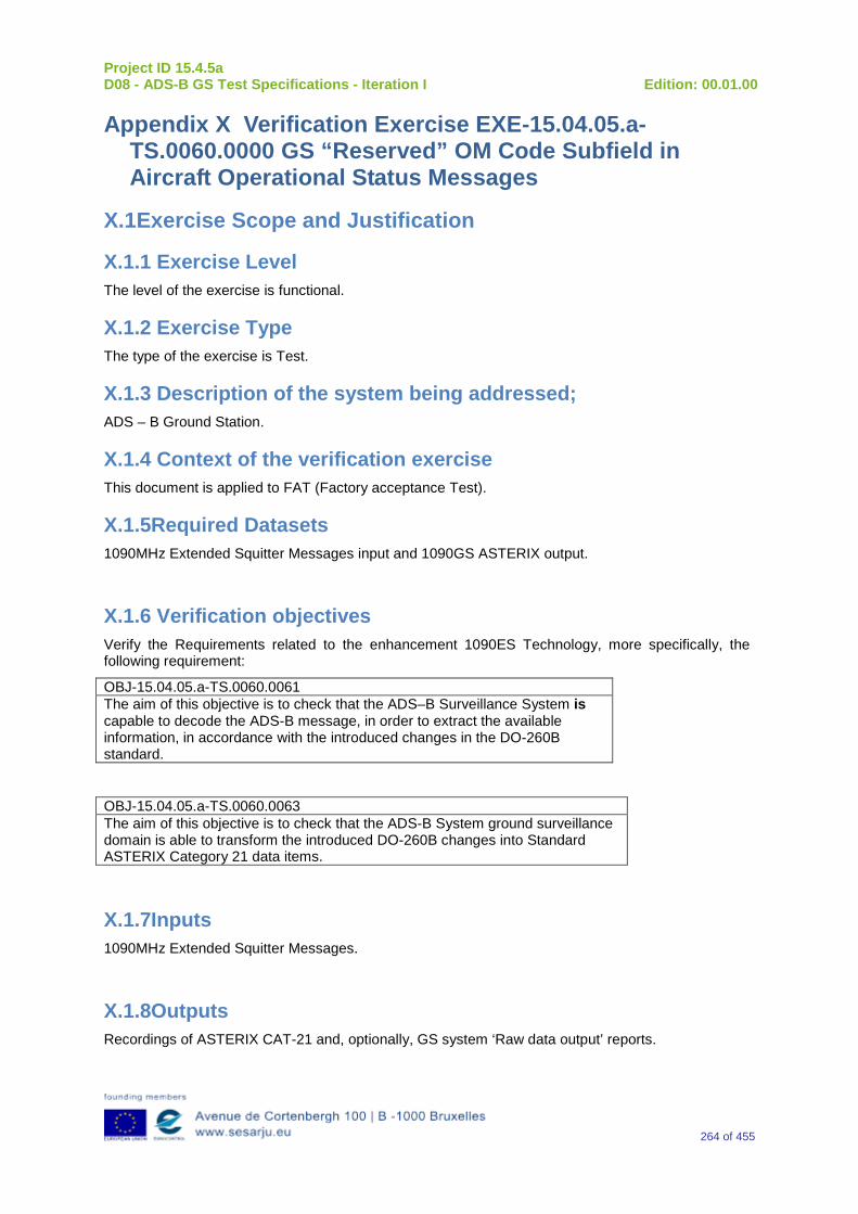
Project ID 15.4.5a D08 - ADS-B GS Test Specifications - Iteration I Edition: 00.01.00
264 of 455
Appendix X Verification Exercise EXE-15.04.05.a-TS.0060.0000 GS “Reserved” OM Code Subfield in Aircraft Operational Status Messages
X.1Exercise Scope and Justification
X.1.1 Exercise Level The level of the exercise is functional.
X.1.2 Exercise Type The type of the exercise is Test.
X.1.3 Description of the system being addressed; ADS – B Ground Station.
X.1.4 Context of the verification exercise This document is applied to FAT (Factory acceptance Test).
X.1.5Required Datasets 1090MHz Extended Squitter Messages input and 1090GS ASTERIX output.
X.1.6 Verification objectives Verify the Requirements related to the enhancement 1090ES Technology, more specifically, the following requirement:
OBJ-15.04.05.a-TS.0060.0061 The aim of this objective is to check that the ADS–B Surveillance System is capable to decode the ADS-B message, in order to extract the available information, in accordance with the introduced changes in the DO-260B standard.
OBJ-15.04.05.a-TS.0060.0063 The aim of this objective is to check that the ADS-B System ground surveillance domain is able to transform the introduced DO-260B changes into Standard ASTERIX Category 21 data items.
X.1.7Inputs 1090MHz Extended Squitter Messages.
X.1.8Outputs Recordings of ASTERIX CAT-21 and, optionally, GS system ‘Raw data output’ reports.
Project ID 15.4.5a D08 - ADS-B GS Test Specifications - Iteration I Edition: 00.01.00
265 of 455
X.1.9 Entrance criteria Start the generation of input data.
X.1.10Exit Criteria Finished recording and performed analysis.
X.1.11 Exercise procedure
Exercise ID/Title: EXE-15.4.5.a-TS.0060.0000 / “Reserved” OM Code Subfield in Aircraft Operational Status Messages
Pass Criteria: This test is passed, when the recorded output has data items and corresponding values as expected.
Exercise Type: Test
Precondition(s): • Test equipment is setup as described above • GS under test is active, and ready for test.
Note(s): N/A
Device(s) in use: SUT is ADS-B GS.
“Reserved” bits, (“ME” bits 33 – 40, Message bits 65 – 72) in the OM Code Subfield of surface format Aircraft Operational Status Messages are reserved for future assignment. Until such future assignment, these bits shall be set to “ZERO” (0). Step 1: Aircraft Operational Status Message Initialization Via the appropriate interface, provide the ADS-B Transmitting Subsystem with appropriate operational status data in order to initialize transmission of Aircraft Operational Status Messages. Step 2: Verification of “Reserved” Bits Verify that Aircraft Operational Status Messages are broadcast with “ME” bits 33 – 40 (Message bits 65 – 72) set to ZERO (0).
Exercise Procedure:
Step Action Expected Reaction Pass/Fail Comment
1 Put the GS system under test into the related test configuration.
Project ID 15.4.5a D08 - ADS-B GS Test Specifications - Iteration I Edition: 00.01.00
266 of 455
2 Prepare the test reporting capture tools to capture related GS system ASTERIX CAT-21 and, optional, GS system ‘Raw Data Output’ reports.
3 Prepare the test message source to play the test scenario.
4 Play the test scenario.
5 When the test scenario is complete, stop the recording of ASTERIX CAT-21 and, optional, GS system ‘Raw data output’ reports.
6 Analyze the recorded data:
7 Input test scenario versus ASTERIX CAT-21 reports and
8 Optional, Input test scenario versus GS system ‘Raw data output reports
9 Verify that the GS system under test has generated the expected outputs, and has fulfilled the test objective.
Exercise result:
Pass Fail Done By (Name, Organisation)
Configuration(s) during the exercise Date
Table 29: Verification Exercise Result
X.1.12 Verification SUT requirements N/A

Project ID 15.4.5a D08 - ADS-B GS Test Specifications - Iteration I Edition: 00.01.00
267 of 455
X.1.13 Exercise Tool, Verification Technique and/or Platform
ADS-BGround Station
Power
ASTERIX(and Raw Data)
Recording
UTC Time Reference
RF Source(Message Generator)
The Exercise will be verified in a platform with the following foreseen tools/equipment:
-Ground Station ADS–B
-Message Generator
-ASTERIX (and Raw Data) Recording Tool
-Power Source
-UTC time Reference
The Item reported above will be capable to perform the functionalities reported below.
Ground Station ADS-B
The primary function of the 1090 GS is to receive 1090 MHz Mode S Extended Squitter messages, extract the data contained therein, and create appropriated ASTERIX Category 21 and 23 Reports (and optionally, Raw Data).
Message Generator
The Messages Generator will be capable to generate the data coming from the Remote System (ADS–B Ground Station or 1090 Receiver) like:
•Target data stream with inside the information extracted by the ADS–B message (ASTERIX CAT 21 in the case of Ground Station or Raw Data in the case that remote system is a 1090 MHz Receiver).
•Operational Data Stream with inside the Remote System’s Operational Status Information (ASTERIX CAT 23 in the case of Ground Station or Raw Data in the case that remote system is a 1090 MHz Receiver).
UTC Time Reference
The UTC Time reference is the solution adopted in the Test Scenario in order to provide the Synchronization in the Ground Station by UTC Time.
ASTERIX Recording Equipment
The ASTERIX recording equipment will be capable to record all ASTERIX reports sent from the 1090 ES Ground Station.
X.1.14 Verification Platform needs See section 3.5 Verification Platform Needs.
Project ID 15.4.5a D08 - ADS-B GS Test Specifications - Iteration I Edition: 00.01.00
268 of 455
X.1.15 Platform Configuration N/A
X.1.16 Configuration(s) Identification of the Verification Platform N/A
X.1.17 Links to other Verification Exercises N/A
X.1.18 Representatively level/ limitations N/A
X.2 Exercises Planning and management
X.2.1 Activities N/A
X.2.1.1 Preparatory activities Setup the tools/equipment listed in 3.5 and X.1.13 in order to meet the Test Preconditions.
X.2.1.2 Execution activities Play the scenario generating in the input the desired messages and record the relevant ASTERIX (and Raw Data) output.
X.2.1.3 Post execution activities The post execution activities will be mainly focused on the analysis of recorded ASTERIX reports (and Raw Data reports). The analysis shall be done in order to verify the right information propagation as requested in each Test Scenario.
X.2.2 Human Resources. N/A
X.2.3Responsibilities in the exercise N/A
X.2.4 Training N/A
X.2.5 Time planning N/A
X.2.6 Risks N/A
Project ID 15.4.5a D08 - ADS-B GS Test Specifications - Iteration I Edition: 00.01.00
269 of 455
X.2.7 Errors and Observation handling N/A
X.3 Analysis Specification
X.3.1 Data collection methods N/A
X.3.2 Analysis method N/A
X.3.3 Data logging requirements N/A
Project ID 15.4.5a D08 - ADS-B GS Test Specifications - Iteration I Edition: 00.01.00
270 of 455
Appendix Y Verification Exercise EXE-15.04.05.a-TS.0060.0010 GS: “Reserved Bit-A” Subfield in Airborne Velocity Messages – Subtype=1
Note: This “Reserved Bit-A” subfield was identified in RTCA DO-260A as the “IFR Capability Flag” subfield, and was required to be set to ONE only for transmitting aircraft that had the capability for applications requiring ADS-B equipage Class “A1” or above. The “IFR Capability Flag” has been eliminated from the ADS-B MASPS (RTCA DO-242B), and so has been removed from these requirements for the 1090ES MOPS.
Y.1Exercise Scope and Justification
Y.1.1 Exercise Level The level of the exercise is functional.
Y.1.2 Exercise Type The type of the exercise is Test.
Y.1.3 Description of the system being addressed; ADS – B Ground Station.
Y.1.4 Context of the verification exercise This document is applied to FAT (Factory acceptance Test).
Y.1.5Required Datasets 1090MHz Extended Squitter Messages input and 1090GS ASTERIX output.
Y.1.6 Verification objectives Verify the Requirements related to the enhancement 1090ES Technology, more specifically, the following requirements:
OBJ-15.04.05.a-TS.0060.0061 The aim of this objective is to check that the ADS–B Surveillance System is capable to decode the ADS-B message, in order to extract the available information, in accordance with the introduced changes in the DO-260B standard.
OBJ-15.04.05.a-TS.0060.0063 The aim of this objective is to check that the ADS-B System ground surveillance domain is able to transform the introduced DO-260B changes into Standard ASTERIX Category 21 data items.
Y.1.7Inputs 1090MHz Extended Squitter Messages.
Project ID 15.4.5a D08 - ADS-B GS Test Specifications - Iteration I Edition: 00.01.00
271 of 455
Y.1.8Outputs Recordings of ASTERIX CAT-21 and, optionally, GS system ‘Raw data output’ reports.
Y.1.9 Entrance criteria Start the generation of the input data.
Y.1.10 Exit Criteria Finished recording and performed analysis.
Y.1.11 Exercise procedure Exercise ID/Title: EXE-15.4.5.a-TS.0060.0010 / “Reserved Bit-A” Subfield in Airborne Velocity Messages – Subtype=1.
Pass Criteria: This test is passed, when the recorded output has data items and
corresponding values as expected.
Exercise Type: Test
Precondition(s): Test equipment is setup as described above GS under test is active, and ready for test.
Note(s): N/A
Device(s) in use: SUT is ADS-B GS.
The “Reserved Bits-A” subfield is a 1-bit (“ME” bit 10, Message bit 42) field that shall be set to ZERO (0) in all ADS-B Transmitting Subsystems that comply with DO-260B. Measurement Procedure: Configure the ADS-B Transmitting Subsystem to broadcast Airborne Velocity Messages – Subtype=1 at the nominal rate. Verify that the “Reserved Bits-A” subfield is set to ZERO (0) in all transmitted messages.
Exercise Procedure:
Step Action Expected Reaction Pass/Fail Comment
1 Put the GS system under test into the related test configuration.
2 Prepare the test reporting capture tools to capture related GS system ASTERIX CAT-21 and,
Project ID 15.4.5a D08 - ADS-B GS Test Specifications - Iteration I Edition: 00.01.00
272 of 455
optional, GS system ‘Raw Data Output’ reports.
3 Prepare the test message source to play the test scenario.
4 Play the test scenario.
5 When the test scenario is complete, stop the recording of ASTERIX CAT-21 and, optional, GS system ‘Raw data output’ reports.
6 Analyze the recorded data:
7 Input test scenario versus ASTERIX CAT-21 reports and
8 Optional, Input test scenario versus GS system ‘Raw data output reports
9 Verify that the GS system under test has generated the expected outputs, and has fulfilled the test objective.
Exercise result:
Pass Fail Done By (Name, Organisation)
Configuration(s) during the exercise Date
Table 30: Verification Exercise Result
Y.1.12 Verification SUT requirements N/A
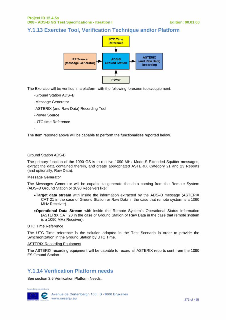
Project ID 15.4.5a D08 - ADS-B GS Test Specifications - Iteration I Edition: 00.01.00
273 of 455
Y.1.13 Exercise Tool, Verification Technique and/or Platform
ADS-BGround Station
Power
ASTERIX(and Raw Data)
Recording
UTC Time Reference
RF Source(Message Generator)
The Exercise will be verified in a platform with the following foreseen tools/equipment:
-Ground Station ADS–B
-Message Generator
-ASTERIX (and Raw Data) Recording Tool
-Power Source
-UTC time Reference
-
The Item reported above will be capable to perform the functionalities reported below.
Ground Station ADS-B
The primary function of the 1090 GS is to receive 1090 MHz Mode S Extended Squitter messages, extract the data contained therein, and create appropriated ASTERIX Category 21 and 23 Reports (and optionally, Raw Data).
Message Generator
The Messages Generator will be capable to generate the data coming from the Remote System (ADS–B Ground Station or 1090 Receiver) like:
•Target data stream with inside the information extracted by the ADS–B message (ASTERIX CAT 21 in the case of Ground Station or Raw Data in the case that remote system is a 1090 MHz Receiver).
•Operational Data Stream with inside the Remote System’s Operational Status Information (ASTERIX CAT 23 in the case of Ground Station or Raw Data in the case that remote system is a 1090 MHz Receiver).
UTC Time Reference
The UTC Time reference is the solution adopted in the Test Scenario in order to provide the Synchronization in the Ground Station by UTC Time.
ASTERIX Recording Equipment
The ASTERIX recording equipment will be capable to record all ASTERIX reports sent from the 1090 ES Ground Station.
Y.1.14 Verification Platform needs See section 3.5 Verification Platform Needs.
Project ID 15.4.5a D08 - ADS-B GS Test Specifications - Iteration I Edition: 00.01.00
274 of 455
Y.1.15 Platform Configuration N/A
Y.1.16 Configuration(s) Identification of the Verification Platform N/A
Y.1.17 Links to other Verification Exercises N/A
Y.1.18 Representatively level/ limitations N/A
Y.2 Exercises Planning and management
Y.2.1 Activities
Y.2.1.1 Preparatory activities Setup the tools/equipment listed in 3.5 and Y.1.13 in order to meet the Test Preconditions.
Y.2.1.2 Execution activities Play the scenario generating in the input the desired messages and record the relevant ASTERIX (and Raw Data) output.
Y.2.1.3 Post execution activities The post execution activities will be mainly focused on the analysis of recorded ASTERIX reports (and Raw Data reports). The analysis shall be done in order to verify the right information propagation as requested in each Test Scenario.
Y.2.2 Human Resources N/A
Y.2.3 Responsibilities in the exercise N/A
Y.2.4 Training N/A
Y.2.5 Time planning N/A
Y.2.6 Risks N/A
Y.2.7 Errors and Observation handling N/A

Project ID 15.4.5a D08 - ADS-B GS Test Specifications - Iteration I Edition: 00.01.00
275 of 455
Y.3 Analysis Specification
Y.3.1 Data collection methods The data collection during the test will be Qualitative. In fact after test execution the analysis of ASTERIX Data will be performed verifying that the values reported in the output are in line with the values generated in the input.
Y.3.2Analysis method N/A
Y.3.3 Data logging requirements The data logging requirements for this scenario will foresee at least ASTERIX CAT 21 items.
Project ID 15.4.5a D08 - ADS-B GS Test Specifications - Iteration I Edition: 00.01.00
276 of 455
Appendix Z Verification Exercise EXE-15.04.05.a-TS.0060.0020-GS “TCAS Operational” Subfield in Target State and Status Messages
Z.1Exercise Scope and Justification
Z.1.1 Exercise Level The level of the exercise is functional.
Z.1.2 Exercise Type The type of the exercise is Test.
Z.1.3 Description of the system being addressed; ADS – B Ground Station.
Z.1.4 Context of the verification exercise This document is applied to FAT (Factory acceptance Test).
Z.1.5Required Datasets 1090MHz Extended Squitter Messages input and 1090GS ASTERIX output.
Z.1.6 Verification objectives Verify the Requirements related to the enhancement 1090ES Technology, more specifically, the following requirements:
OBJ-15.04.05.a-TS.0060.0061 The aim of this objective is to check that the ADS–B Surveillance System is capable to decode the ADS-B message, in order to extract the available information, in accordance with the introduced changes in the DO-260B standard.
OBJ-15.04.05.a-TS.0060.0063 The aim of this objective is to check that the ADS-B System ground surveillance domain is able to transform the introduced DO-260B changes into Standard ASTERIX Category 21 data items.
Z.1.7Inputs 1090MHz Extended Squitter Messages.
Z.1.8Outputs Recordings of ASTERIX CAT-21 and, optional, GS system ‘Raw data output’ reports.
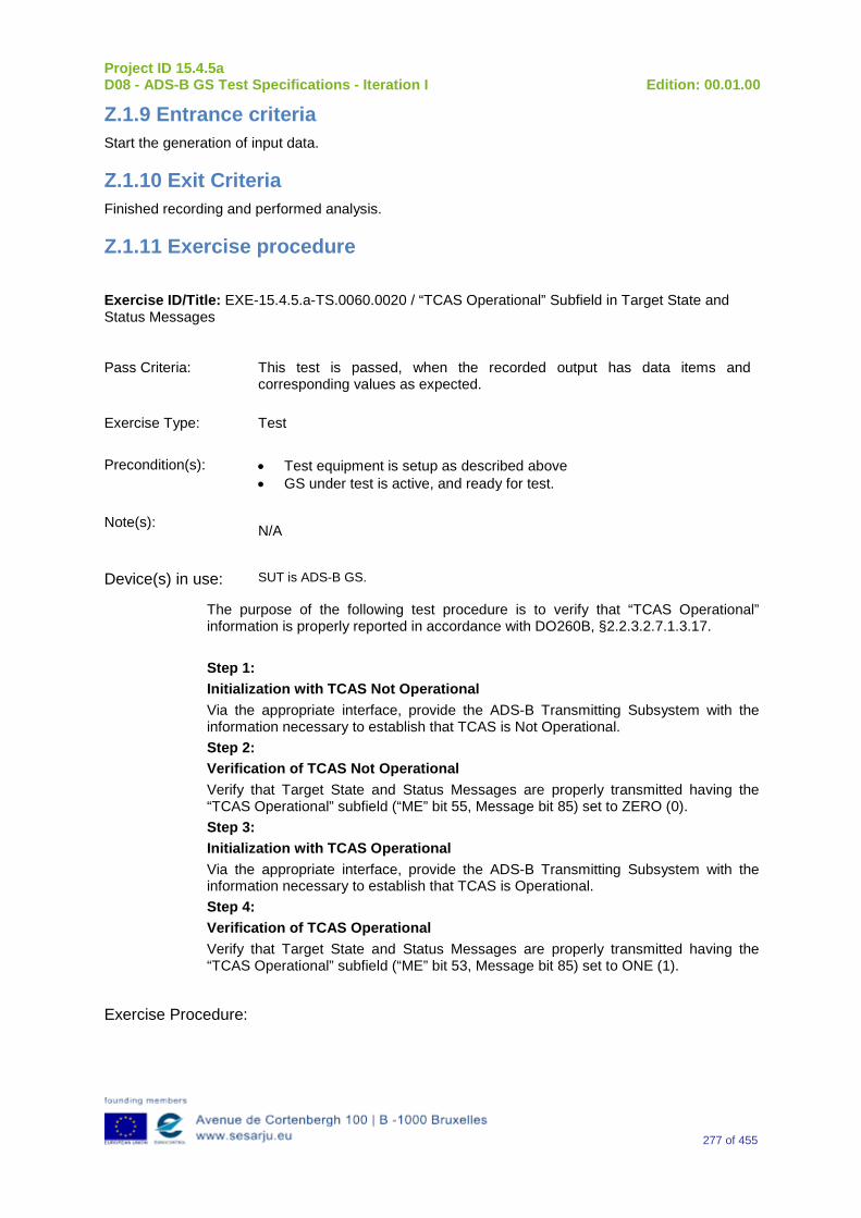
Project ID 15.4.5a D08 - ADS-B GS Test Specifications - Iteration I Edition: 00.01.00
277 of 455
Z.1.9 Entrance criteria Start the generation of input data.
Z.1.10 Exit Criteria Finished recording and performed analysis.
Z.1.11 Exercise procedure
Exercise ID/Title: EXE-15.4.5.a-TS.0060.0020 / “TCAS Operational” Subfield in Target State and Status Messages
Pass Criteria: This test is passed, when the recorded output has data items and corresponding values as expected.
Exercise Type: Test
Precondition(s): • Test equipment is setup as described above • GS under test is active, and ready for test.
Note(s): N/A
Device(s) in use: SUT is ADS-B GS.
The purpose of the following test procedure is to verify that “TCAS Operational” information is properly reported in accordance with DO260B, §2.2.3.2.7.1.3.17. Step 1: Initialization with TCAS Not Operational Via the appropriate interface, provide the ADS-B Transmitting Subsystem with the information necessary to establish that TCAS is Not Operational. Step 2: Verification of TCAS Not Operational Verify that Target State and Status Messages are properly transmitted having the “TCAS Operational” subfield (“ME” bit 55, Message bit 85) set to ZERO (0). Step 3: Initialization with TCAS Operational Via the appropriate interface, provide the ADS-B Transmitting Subsystem with the information necessary to establish that TCAS is Operational. Step 4: Verification of TCAS Operational Verify that Target State and Status Messages are properly transmitted having the “TCAS Operational” subfield (“ME” bit 53, Message bit 85) set to ONE (1).
Exercise Procedure:

Project ID 15.4.5a D08 - ADS-B GS Test Specifications - Iteration I Edition: 00.01.00
278 of 455
Step Action Expected Reaction Pass/Fail Comment
1 Put the GS system under test into the related test configuration.
2 Prepare the test reporting capture tools to capture related GS system ASTERIX CAT-21 and, optional, GS system ‘Raw Data Output’ reports.
3 Prepare the test message source to play the test scenario.
4 Play the test scenario.
5 When the test scenario is complete, stop the recording of ASTERIX CAT-21 and, optional, GS system ‘Raw data output’ reports.
6 Analyze the recorded data:
7 Input test scenario versus ASTERIX CAT-21 reports and
8 Optional, Input test scenario versus GS system ‘Raw data output reports
9 Verify that the GS system under test has generated the expected outputs, and has fulfilled the test objective.
Exercise result:
Pass Fail Done By (Name, Organisation)
Configuration(s) during the exercise Date
Table 31: Verification Exercise Result

Project ID 15.4.5a D08 - ADS-B GS Test Specifications - Iteration I Edition: 00.01.00
279 of 455
Z.1.12 Verification SUT requirements N/A
Z.1.13 Exercise Tool, Verification Technique and/or Platform
ADS-BGround Station
Power
ASTERIX(and Raw Data)
Recording
UTC Time Reference
RF Source(Message Generator)
The Exercise will be verified in a platform with the following foreseen tools/equipment:
-Ground Station ADS–B
-Message Generator
-ASTERIX (and Raw Data) Recording Tool
-Power Source
-UTC time Reference
The Item reported above will be capable to perform the functionalities reported below.
Ground Station ADS-B
The primary function of the 1090 GS is to receive 1090 MHz Mode S Extended Squitter messages, extract the data contained therein, and create appropriated ASTERIX Category 21 and 23 Reports (and optionally, Raw Data).
Message Generator
The Messages Generator will be capable to generate the data coming from the Remote System (ADS–B Ground Station or 1090 Receiver) like:
•Target data stream with inside the information extracted by the ADS–B message (ASTERIX CAT 21 in the case of Ground Station or Raw Data in the case that remote system is a 1090 MHz Receiver).
•Operational Data Stream with inside the Remote System’s Operational Status Information (ASTERIX CAT 23 in the case of Ground Station or Raw Data in the case that remote system is a 1090 MHz Receiver).
UTC Time Reference
The UTC Time reference is the solution adopted in the Test Scenario in order to provide the Synchronization in the Ground Station by UTC Time.
ASTERIX Recording Equipment
The ASTERIX recording equipment will be capable to record all ASTERIX reports sent from the 1090 ES Ground Station.
Project ID 15.4.5a D08 - ADS-B GS Test Specifications - Iteration I Edition: 00.01.00
280 of 455
Z.1.14 Verification Platform needs See section 3.5 Verification Platform Needs
Z.1.15 Platform Configuration N/A
Z.1.16 Configuration(s) Identification of the Verification Platform N/A
Z.1.17 Links to other Verification Exercises N/A
Z.1.18 Representatively level/ limitations N/A
Z.2 Exercises Planning and management
Z.2.1 Activities N/A
Z.2.1.1 Preparatory activities Setup the tools/equipment listed in 3.5 and Z.1.13 in order to meet the Test Preconditions.
Z.2.1.2 Execution activities Play the scenario generating in the input the desired messages and record the relevant ASTERIX (and Raw Data) output.
Z.2.1.3 Post execution activities The post execution activities will be mainly focused on the analysis of recorded ASTERIX reports (and Raw Data reports). The analysis shall be done in order to verify the right information propagation as requested in each Test Scenario.
Z.2.2 Human Resources N/A
Z.2.3 Responsibilities in the exercise N/A
Z.2.4 Training N/A
Z.2.5 Time planning N/A
Project ID 15.4.5a D08 - ADS-B GS Test Specifications - Iteration I Edition: 00.01.00
281 of 455
Z.2.6 Risks N/A
Z.2.7 Errors and Observation handling N/A
Z.3 Analysis Specification
Z.3.1 Data collection methods The data collection during the test will be Qualitative. In fact after test execution the analysis of ASTERIX Data will be performed verifying that the values reported in the output are in line with the values generated in the input.
Z.3.2Analysis method N/A
Z.3.3 Data logging requirements The data logging requirements for this scenario will foresee at least ASTERIX CAT 21 items.
Project ID 15.4.5a D08 - ADS-B GS Test Specifications - Iteration I Edition: 00.01.00
282 of 455
Appendix AA Verification Exercise EXE-15.04.05.a-TS.0060.0030 GS “Geometric Vertical Accuracy (GVA)” Subfield in Aircraft Operational Status Messages
AA.1 Exercise Scope and Justification
AA.1.1 Exercise Level The level of the exercise is functional.
AA.1.2 Exercise Type The type of the exercise is Test.
AA.1.3 Description of the system being addressed; ADS – B Ground Station.
AA.1.4 Context of the verification exercise This document is applied to FAT (Factory acceptance Test).
AA.1.5 Required Datasets 1090MHz Extended Squitter Messages input and 1090GS ASTERIX output.
AA.1.6 Verification objectives Verify the Requirements related to the enhancement 1090ES Technology, more specifically, the following requirements:
OBJ-15.04.05.a-TS.0060.0061 The aim of this objective is to check that the ADS–B Surveillance System is capable to decode the ADS-B message, in order to extract the available information, in accordance with the introduced changes in the DO-260B standard.
OBJ-15.04.05.a-TS.0060.0063 The aim of this objective is to check that the ADS-B System ground surveillance domain is able to transform the introduced DO-260B changes into Standard ASTERIX Category 21 data items.
AA.1.7 Inputs 1090MHz Extended Squitter Messages.
AA.1.8 Outputs Recordings of ASTERIX CAT 21 and, optionally, GS system ‘Raw data output’ reports.
Project ID 15.4.5a D08 - ADS-B GS Test Specifications - Iteration I Edition: 00.01.00
283 of 455
AA.1.9 Entrance criteria Start the generation of the input data.
AA.1.10 Exit Criteria Finished recording and performed analysis.
AA.1.11 Exercise procedure
Exercise ID/Title: EXE-15.4.5.a-TS.0060.0030 / “Geometric Vertical Accuracy (GVA)” Subfield in Aircraft Operational Status Messages
Pass Criteria: This test is passed, when the recorded output has data items and corresponding values as expected.
Exercise Type: Test
Precondition(s): • Test equipment is setup as described above • GS under test is active, and ready for test.
Note(s): N/A
Device(s) in use: SUT is ADS-B GS.
The “Geometric Vertical Accuracy (GVA)” subfield of Subtype=0 Aircraft Operational Status Message is a 2-bit field (“ME” bits 49-50, Message bits 81-82) defined in Table 32. The GVA field is set by using the Vertical Figure of Merit (VFOM) (95%) from the GNSS position source used to encode the geometric altitude field in the Airborne Position Message. Step 1: Verification of GVA Transmission Configure the ADS-B Transmitting Subsystem to transmit Aircraft Operational Status Messages by providing valid operational status information at the nominal update rate. Set the Vertical Figure of Merit (VFOM) field to each of the following values in Table 32 and verify that the corresponding encoding is set in the GVA field of the Aircraft Operational Status Message.
Table 32: Geometric Vertical Accuracy Validation Values
Row VFOM (meters) GVA Encoding
1 Invalid 0 2 30.0 1 3 44.5 1 4 45.5 0 5 327.1 0
Step 2: Verification of GVA – Data Lifetime
Project ID 15.4.5a D08 - ADS-B GS Test Specifications - Iteration I Edition: 00.01.00
284 of 455
Rerun Table 32, Row 2 from Step 1. Remove the data source input for GVA for a period of at least 2 seconds. Verify that the GVA subfield of the Aircraft Operational Status Message is set to ZERO (binary 00).
Exercise Procedure:
Step Action Expected Reaction Pass/Fail Comment
1 Put the GS system under test into the related test configuration.
2 Prepare the test reporting capture tools to capture related GS system ASTERIX CAT-21 and, optional, GS system ‘Raw Data Output’ reports.
3 Prepare the test message source to play the test scenario.
4 Play the test scenario.
5 When the test scenario is complete, stop the recording of ASTERIX CAT-21 and, optional, GS system ‘Raw data output’ reports.
6 Analyze the recorded data:
7 Input test scenario versus ASTERIX CAT-21 reports and
8 Optional, Input test scenario versus GS system ‘Raw data output reports
9 Verify that the GS system under test has generated the expected outputs, and has fulfilled the test objective.
Exercise result:
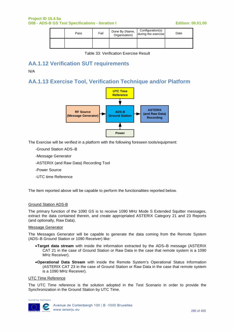
Project ID 15.4.5a D08 - ADS-B GS Test Specifications - Iteration I Edition: 00.01.00
285 of 455
Pass Fail Done By (Name, Organisation)
Configuration(s) during the exercise Date
Table 33: Verification Exercise Result
AA.1.12 Verification SUT requirements N/A
AA.1.13 Exercise Tool, Verification Technique and/or Platform
ADS-BGround Station
Power
ASTERIX(and Raw Data)
Recording
UTC Time Reference
RF Source(Message Generator)
The Exercise will be verified in a platform with the following foreseen tools/equipment:
-Ground Station ADS–B
-Message Generator
-ASTERIX (and Raw Data) Recording Tool
-Power Source
-UTC time Reference
The Item reported above will be capable to perform the functionalities reported below.
Ground Station ADS-B
The primary function of the 1090 GS is to receive 1090 MHz Mode S Extended Squitter messages, extract the data contained therein, and create appropriated ASTERIX Category 21 and 23 Reports (and optionally, Raw Data).
Message Generator
The Messages Generator will be capable to generate the data coming from the Remote System (ADS–B Ground Station or 1090 Receiver) like:
•Target data stream with inside the information extracted by the ADS–B message (ASTERIX CAT 21 in the case of Ground Station or Raw Data in the case that remote system is a 1090 MHz Receiver).
•Operational Data Stream with inside the Remote System’s Operational Status Information (ASTERIX CAT 23 in the case of Ground Station or Raw Data in the case that remote system is a 1090 MHz Receiver).
UTC Time Reference
The UTC Time reference is the solution adopted in the Test Scenario in order to provide the Synchronization in the Ground Station by UTC Time.
Project ID 15.4.5a D08 - ADS-B GS Test Specifications - Iteration I Edition: 00.01.00
286 of 455
ASTERIX Recording Equipment
The ASTERIX recording equipment will be capable to record all ASTERIX reports sent from the 1090 ES Ground Station.
AA.1.14 Verification Platform needs See section 3.5 Verification Platform Needs.
AA.1.15 Platform Configuration N/A
AA.1.16 Configuration(s) Identification of the Verification Platform N/A
AA.1.17 Links to other Verification Exercises N/A
AA.1.18 Representatively level/ limitations N/A
AA.2 Exercises Planning and management
AA.2.1 Activities N/A
AA.2.1.1 Preparatory activities Setup the tools/equipment listed in 3.5 and AA.1.13 in order to meet the Test Preconditions.
AA.2.1.2 Execution activities Play the scenario generating in the input the desired messages and record the relevant ASTERIX (and Raw Data) output.
AA.2.1.3 Post execution activities The post execution activities will be mainly focused on the analysis of recorded ASTERIX reports (and Raw Data reports). The analysis shall be done in order to verify the right information propagation as requested in each Test Scenario.
AA.2.2 Human Resources N/A
AA.2.3 Responsibilities in the exercise N/A
AA.2.4 Training N/A
Project ID 15.4.5a D08 - ADS-B GS Test Specifications - Iteration I Edition: 00.01.00
287 of 455
AA.2.5 Time planning N/A
AA.2.6 Risks N/A
AA.2.7 Errors and Observation handling N/A
AA.3 Analysis Specification
AA.3.1 Data collection methods The data collection during the test will be Qualitative. In fact after the test execution the analysis of ASTERIX Data will be performed verifying that the values reported in the output are in line with the values generated in the input.
AA.3.2 Analysis method N/A
AA.3.3 Data logging requirements The data logging requirements for this scenario will foresee at least ASTERIX CAT 21 items.
Project ID 15.4.5a D08 - ADS-B GS Test Specifications - Iteration I Edition: 00.01.00
288 of 455
Appendix BB Verification Exercise EXE-15.04.05.a-TS.0060.0040-GS “GPS Antenna Offset” OM Code Subfield in Aircraft Operational Status Messages
BB.1 Exercise Scope and Justification
BB.1.1 Exercise Level The level of the exercise is functional.
BB.1.2 Exercise Type The type of the exercise is Test.
BB.1.3 Description of the system being addressed; ADS – B Ground Station.
BB.1.4 Context of the verification exercise This document is applied to FAT (Factory acceptance Test).
BB.1.5Required Datasets 1090MHz Extended Squitter Messages input and 1090GS ASTERIX output.
BB.1.6 Verification objectives Verify the Requirements related to the enhancement 1090ES Technology, more specifically, the following requirements:
OBJ-15.04.05.a-TS.0060.0061 The aim of this objective is to check that the ADS–B Surveillance System is capable to decode the ADS-B message, in order to extract the available information, in accordance with the introduced changes in the DO-260B standard.
OBJ-15.04.05.a-TS.0060.0063 The aim of this objective is to check that the ADS-B System ground surveillance domain is able to transform the introduced DO-260B changes into Standard ASTERIX Category 21 data items.
BB.1.7 Inputs 1090MHz Extended Squitter Messages.
BB.1.8 Outputs Recordings of ASTERIX CAT 21 and, optionally, GS system ‘Raw data output’ reports.
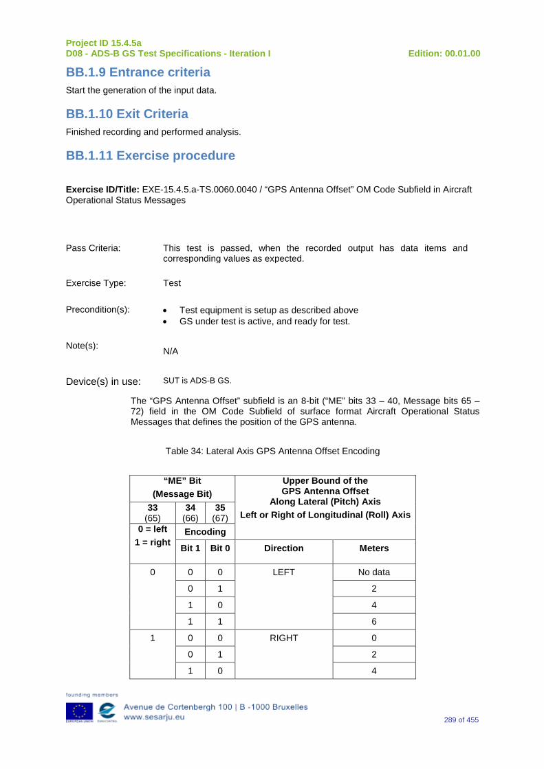
Project ID 15.4.5a D08 - ADS-B GS Test Specifications - Iteration I Edition: 00.01.00
289 of 455
BB.1.9 Entrance criteria Start the generation of the input data.
BB.1.10 Exit Criteria Finished recording and performed analysis.
BB.1.11 Exercise procedure
Exercise ID/Title: EXE-15.4.5.a-TS.0060.0040 / “GPS Antenna Offset” OM Code Subfield in Aircraft Operational Status Messages
Pass Criteria: This test is passed, when the recorded output has data items and corresponding values as expected.
Exercise Type: Test
Precondition(s): • Test equipment is setup as described above • GS under test is active, and ready for test.
Note(s): N/A
Device(s) in use: SUT is ADS-B GS.
The “GPS Antenna Offset” subfield is an 8-bit (“ME” bits 33 – 40, Message bits 65 – 72) field in the OM Code Subfield of surface format Aircraft Operational Status Messages that defines the position of the GPS antenna.
Table 34: Lateral Axis GPS Antenna Offset Encoding
“ME” Bit
(Message Bit) Upper Bound of the GPS Antenna Offset
Along Lateral (Pitch) Axis Left or Right of Longitudinal (Roll) Axis
33 (65)
34 (66)
35 (67)
0 = left 1 = right
Encoding
Bit 1 Bit 0 Direction Meters
0 0 0 LEFT No data
0 1 2
1 0 4
1 1 6
1 0 0 RIGHT 0
0 1 2
1 0 4
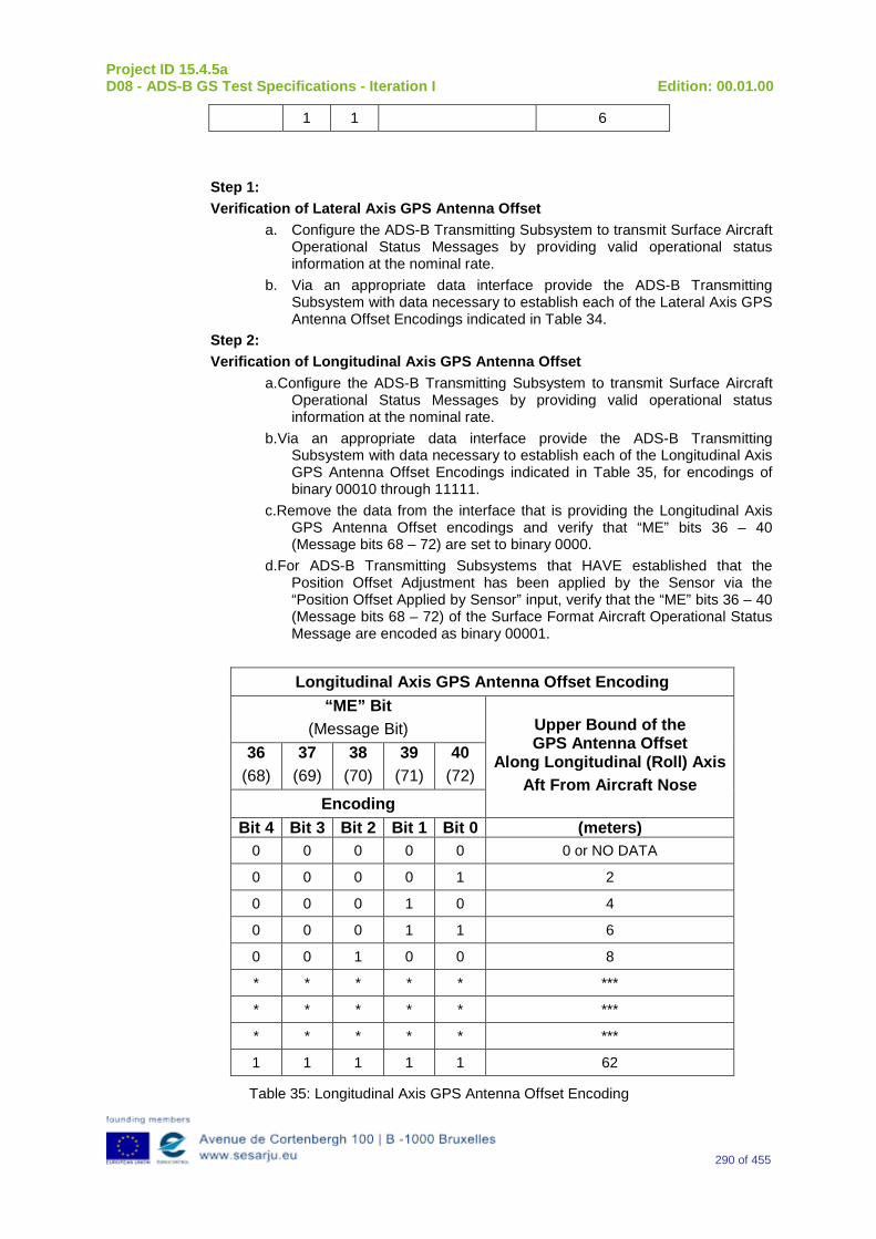
Project ID 15.4.5a D08 - ADS-B GS Test Specifications - Iteration I Edition: 00.01.00
290 of 455
1 1 6
Step 1: Verification of Lateral Axis GPS Antenna Offset
a. Configure the ADS-B Transmitting Subsystem to transmit Surface Aircraft Operational Status Messages by providing valid operational status information at the nominal rate.
b. Via an appropriate data interface provide the ADS-B Transmitting Subsystem with data necessary to establish each of the Lateral Axis GPS Antenna Offset Encodings indicated in Table 34.
Step 2: Verification of Longitudinal Axis GPS Antenna Offset
a. Configure the ADS-B Transmitting Subsystem to transmit Surface Aircraft Operational Status Messages by providing valid operational status information at the nominal rate.
b. Via an appropriate data interface provide the ADS-B Transmitting Subsystem with data necessary to establish each of the Longitudinal Axis GPS Antenna Offset Encodings indicated in Table 35, for encodings of binary 00010 through 11111.
c.Remove the data from the interface that is providing the Longitudinal Axis GPS Antenna Offset encodings and verify that “ME” bits 36 – 40 (Message bits 68 – 72) are set to binary 0000.
d. For ADS-B Transmitting Subsystems that HAVE established that the Position Offset Adjustment has been applied by the Sensor via the “Position Offset Applied by Sensor” input, verify that the “ME” bits 36 – 40 (Message bits 68 – 72) of the Surface Format Aircraft Operational Status Message are encoded as binary 00001.
Longitudinal Axis GPS Antenna Offset Encoding “ME” Bit
(Message Bit) Upper Bound of the GPS Antenna Offset
Along Longitudinal (Roll) Axis Aft From Aircraft Nose
36 (68)
37 (69)
38 (70)
39 (71)
40 (72)
Encoding Bit 4 Bit 3 Bit 2 Bit 1 Bit 0 (meters)
0 0 0 0 0 0 or NO DATA
0 0 0 0 1 2
0 0 0 1 0 4
0 0 0 1 1 6
0 0 1 0 0 8
* * * * * ***
* * * * * ***
* * * * * ***
1 1 1 1 1 62
Table 35: Longitudinal Axis GPS Antenna Offset Encoding
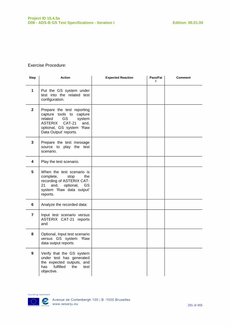
Project ID 15.4.5a D08 - ADS-B GS Test Specifications - Iteration I Edition: 00.01.00
291 of 455
Exercise Procedure:
Step Action Expected Reaction Pass/Fail
Comment
1 Put the GS system under test into the related test configuration.
2 Prepare the test reporting capture tools to capture related GS system ASTERIX CAT-21 and, optional, GS system ‘Raw Data Output’ reports.
3 Prepare the test message source to play the test scenario.
4 Play the test scenario.
5 When the test scenario is complete, stop the recording of ASTERIX CAT-21 and, optional, GS system ‘Raw data output’ reports.
6 Analyze the recorded data:
7 Input test scenario versus ASTERIX CAT-21 reports and
8 Optional, Input test scenario versus GS system ‘Raw data output reports
9 Verify that the GS system under test has generated the expected outputs, and has fulfilled the test objective.
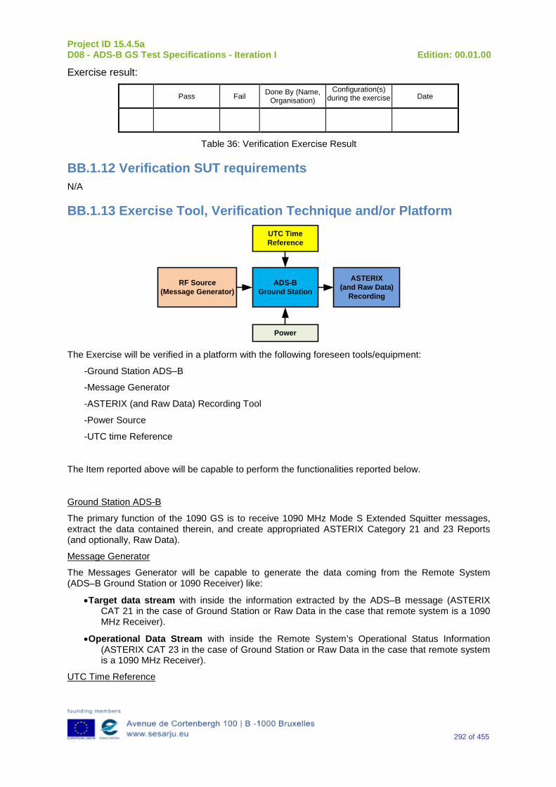
Project ID 15.4.5a D08 - ADS-B GS Test Specifications - Iteration I Edition: 00.01.00
292 of 455
Exercise result:
Pass Fail Done By (Name, Organisation)
Configuration(s) during the exercise Date
Table 36: Verification Exercise Result
BB.1.12 Verification SUT requirements N/A
BB.1.13 Exercise Tool, Verification Technique and/or Platform
ADS-BGround Station
Power
ASTERIX(and Raw Data)
Recording
UTC Time Reference
RF Source(Message Generator)
The Exercise will be verified in a platform with the following foreseen tools/equipment:
-Ground Station ADS–B
-Message Generator
-ASTERIX (and Raw Data) Recording Tool
-Power Source
-UTC time Reference
The Item reported above will be capable to perform the functionalities reported below.
Ground Station ADS-B
The primary function of the 1090 GS is to receive 1090 MHz Mode S Extended Squitter messages, extract the data contained therein, and create appropriated ASTERIX Category 21 and 23 Reports (and optionally, Raw Data).
Message Generator
The Messages Generator will be capable to generate the data coming from the Remote System (ADS–B Ground Station or 1090 Receiver) like:
•Target data stream with inside the information extracted by the ADS–B message (ASTERIX CAT 21 in the case of Ground Station or Raw Data in the case that remote system is a 1090 MHz Receiver).
•Operational Data Stream with inside the Remote System’s Operational Status Information (ASTERIX CAT 23 in the case of Ground Station or Raw Data in the case that remote system is a 1090 MHz Receiver).
UTC Time Reference
Project ID 15.4.5a D08 - ADS-B GS Test Specifications - Iteration I Edition: 00.01.00
293 of 455
The UTC Time reference is the solution adopted in the Test Scenario in order to provide the Synchronization in the Ground Station by UTC Time.
ASTERIX Recording Equipment
The ASTERIX recording equipment will be capable to record all ASTERIX reports sent from the 1090 ES Ground Station.
BB.1.14 Verification Platform needs See section 3.5 Verification Platform Needs.
BB.1.15 Platform Configuration N/A
BB.1.16 Configuration(s) Identification of the Verification Platform N/A
BB.1.17 Links to other Verification Exercises N/A
BB.1.18 Representatively level/ limitations N/A
BB.2 Exercises Planning and management
BB.2.1 Activities N/A
BB.2.1.1 Preparatory activities Setup the tools/equipment listed in 3.5 and BB.1.13 in order to meet the Test Preconditions.
BB.2.1.2 Execution activities Play the scenario generating in the input the desired messages and record the relevant ASTERIX (and Raw Data) output.
BB.2.1.3 Post execution activities The post execution activities will be mainly focused on the analysis of recorded ASTERIX reports (and Raw Data reports). The analysis shall be done in order to verify the right information propagation as requested in each Test Scenario.
BB.2.2 Human Resources N/A
BB.2.3 Responsibilities in the exercise N/A
Project ID 15.4.5a D08 - ADS-B GS Test Specifications - Iteration I Edition: 00.01.00
294 of 455
BB.2.4 Training N/A
BB.2.5 Time planning N/A
BB.2.6 Risks N/A
BB.2.7 Errors and Observation handling N/A
BB.3 Analysis Specification
BB.3.1 Data collection methods The data collection during the test will be Qualitative. In fact after test execution the analysis of ASTERIX Data will be performed verifying that the values reported in the output are in line with the values generated in the input.
BB.3.2 Analysis method N/A
BB.3.3 Data logging requirements The data logging requirements for this scenario will foresee at least ASTERIX CAT 21 items.
Project ID 15.4.5a D08 - ADS-B GS Test Specifications - Iteration I Edition: 00.01.00
295 of 455
Appendix CC Verification Exercise EXE-15.04.05.a-TS.0060.0050 GS: “Source Integrity Level (SIL)” Subfield in Aircraft Operational Status Messages
CC.1 Exercise Scope and Justification
CC.1.1 Exercise Level The level of the exercise is functional.
CC.1.2 Exercise Type The type of the exercise is Test.
CC.1.3 Description of the system being addressed; ADS – B Ground Station.
CC.1.4 Context of the verification exercise This document is applied to FAT (Factory acceptance Test).
CC.1.5Required Datasets 1090MHz Extended Squitter Messages input and 1090GS ASTERIX output.
CC.1.6 Verification objectives Verify the Requirements related to the enhancement 1090ES Technology, more specifically, the following requirements:
OBJ-15.04.05.a-TS.0060.0061 The aim of this objective is to check that the ADS–B Surveillance System is capable to decode the ADS-B message, in order to extract the available information, in accordance with the introduced changes in the DO-260B standard.
OBJ-15.04.05.a-TS.0060.0063 The aim of this objective is to check that the ADS-B System ground surveillance domain is able to transform the introduced DO-260B changes into Standard ASTERIX Category 21 data items.
CC.1.7 Inputs 1090MHz Extended Squitter Messages.
CC.1.8 Outputs Recordings of ASTERIX CAT 21 and, optionally, GS system ‘Raw data output’ reports.
Project ID 15.4.5a D08 - ADS-B GS Test Specifications - Iteration I Edition: 00.01.00
296 of 455
CC.1.9 Entrance criteria Start the generation of the input data.
CC.1.10 Exit Criteria Finished recording and performed analysis.
CC.1.11 Exercise procedure
Exercise ID/Title: EXE-15.4.5.a-TS.0060.0050 / “Source Integrity Level (SIL)” Subfield in Aircraft Operational Status Messages
Pass Criteria: This test is passed, when the recorded output has data items and corresponding values as expected.
Exercise Type: Test
Precondition(s): • Test equipment is setup as described above • GS under test is active, and ready for test.
Note(s): N/A
Device(s) in use: SUT is ADS-B GS.
The Source Integrity Level (SIL) is a 2-bit subfield of “Subtype=0” ADS-B Aircraft Operational Status Messages (“ME” bits 51 and 52, Message bits 83 and 84) that defines the probability of the reported horizontal position exceeding the radius of containment defined by the NIC, without alerting, assuming no avionics faults. Although the SIL assumes there are no unannunciated faults in the avionics system, the SIL must consider the effects of a faulted Signal-in-Space, if a Signal-in-Space is used by the position source. Table 37 defines the meaning of each SIL value. For installations where the SIL value is being dynamically updated, if an update has not been received from an on-board data source for SIL within the past 2 seconds, then the SIL subfield is set to a value of ZERO (0), indicating “Unknown.” Step 1: Verification of SIL Transmission Configure the ADS-B Transmitting Subsystem to transmit Aircraft Operational Status Messages by providing valid operational status information at the nominal update rate. Provide the data externally at the interface to the ADS-B system. Verify that for each “SIL” parameter input condition that is specified by the probability of exceeding the RC Integrity Containment Radius without detection (i.e., the values in Table 37), that the system generates ADS-B Messages with the “SIL” subfield set equal to the corresponding binary coding value shown in Table 37.
Table 37: “SIL” Subfield Encoding
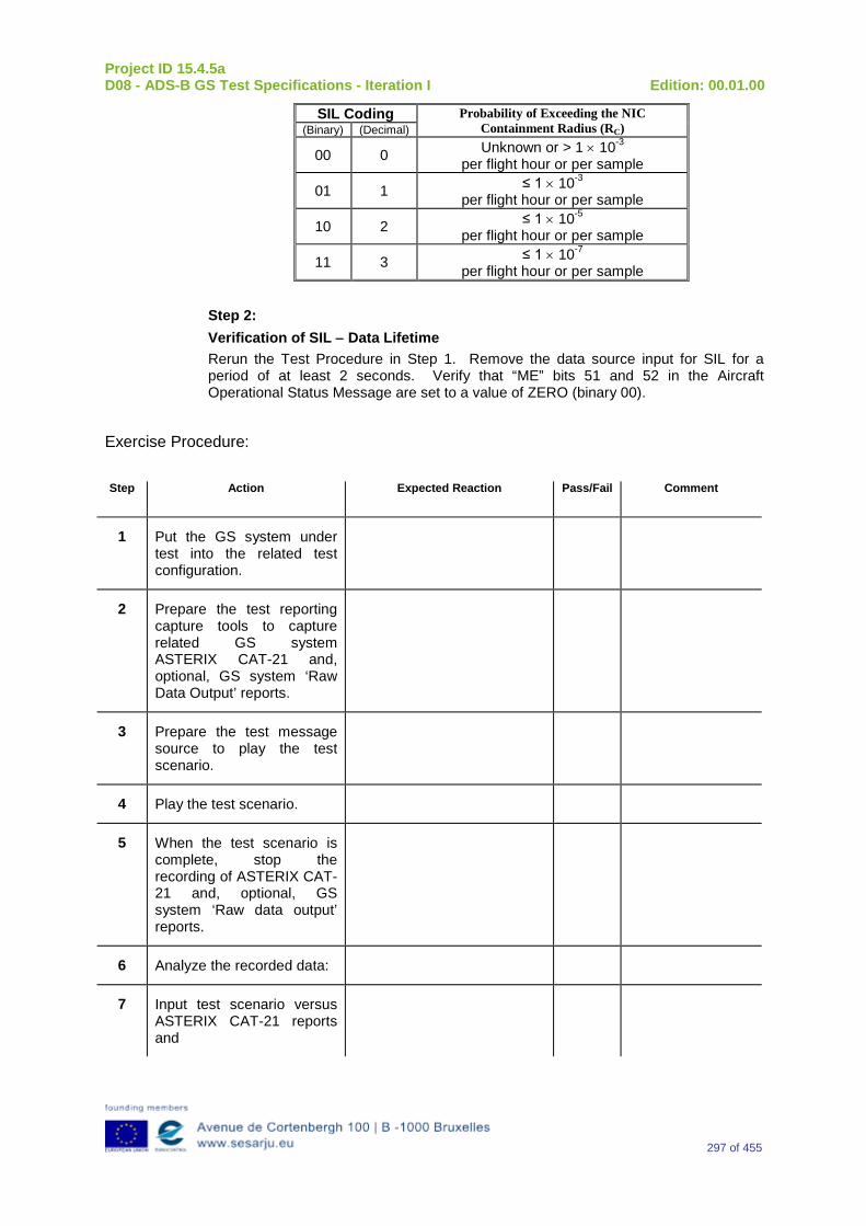
Project ID 15.4.5a D08 - ADS-B GS Test Specifications - Iteration I Edition: 00.01.00
297 of 455
SIL Coding Probability of Exceeding the NIC Containment Radius (RC) (Binary) (Decimal)
00 0 Unknown or > 1 × 10⁻³ per flight hour or per sample
01 1 ≤ 1 × 10⁻³ per flight hour or per sample
10 2 ≤ 1 × 10⁻⁵ per flight hour or per sample
11 3 ≤ 1 × 10⁻⁷ per flight hour or per sample
Step 2: Verification of SIL − Data Lifetime Rerun the Test Procedure in Step 1. Remove the data source input for SIL for a period of at least 2 seconds. Verify that “ME” bits 51 and 52 in the Aircraft Operational Status Message are set to a value of ZERO (binary 00).
Exercise Procedure:
Step Action Expected Reaction Pass/Fail Comment
1 Put the GS system under test into the related test configuration.
2 Prepare the test reporting capture tools to capture related GS system ASTERIX CAT-21 and, optional, GS system ‘Raw Data Output’ reports.
3 Prepare the test message source to play the test scenario.
4 Play the test scenario.
5 When the test scenario is complete, stop the recording of ASTERIX CAT-21 and, optional, GS system ‘Raw data output’ reports.
6 Analyze the recorded data:
7 Input test scenario versus ASTERIX CAT-21 reports and
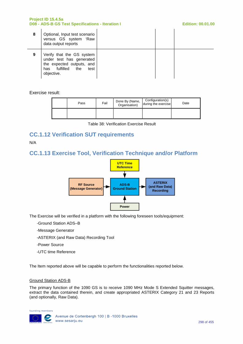
Project ID 15.4.5a D08 - ADS-B GS Test Specifications - Iteration I Edition: 00.01.00
298 of 455
8 Optional, Input test scenario versus GS system ‘Raw data output reports
9 Verify that the GS system under test has generated the expected outputs, and has fulfilled the test objective.
Exercise result:
Pass Fail Done By (Name, Organisation)
Configuration(s) during the exercise Date
Table 38: Verification Exercise Result
CC.1.12 Verification SUT requirements N/A
CC.1.13 Exercise Tool, Verification Technique and/or Platform
ADS-BGround Station
Power
ASTERIX(and Raw Data)
Recording
UTC Time Reference
RF Source(Message Generator)
The Exercise will be verified in a platform with the following foreseen tools/equipment:
-Ground Station ADS–B
-Message Generator
-ASTERIX (and Raw Data) Recording Tool
-Power Source
-UTC time Reference
The Item reported above will be capable to perform the functionalities reported below.
Ground Station ADS-B
The primary function of the 1090 GS is to receive 1090 MHz Mode S Extended Squitter messages, extract the data contained therein, and create appropriated ASTERIX Category 21 and 23 Reports (and optionally, Raw Data).
Project ID 15.4.5a D08 - ADS-B GS Test Specifications - Iteration I Edition: 00.01.00
299 of 455
Message Generator
The Messages Generator will be capable to generate the data coming from the Remote System (ADS–B Ground Station or 1090 Receiver) like:
•Target data stream with inside the information extracted by the ADS–B message (ASTERIX CAT 21 in the case of Ground Station or Raw Data in the case that remote system is a 1090 MHz Receiver).
•Operational Data Stream with inside the Remote System’s Operational Status Information (ASTERIX CAT 23 in the case of Ground Station or Raw Data in the case that remote system is a 1090 MHz Receiver).
UTC Time Reference
The UTC Time reference is the solution adopted in the Test Scenario in order to provide the Synchronization in the Ground Station by UTC Time.
ASTERIX Recording Equipment
The ASTERIX recording equipment will be capable to record all ASTERIX reports sent from the 1090 ES Ground Station.
CC.1.14 Verification Platform needs See section 3.5 Verification Platform Needs.
CC.1.15 Platform Configuration N/A
CC.1.16 Configuration(s) Identification of the Verification Platform N/A
CC.1.17 Links to other Verification Exercises N/A
CC.1.18 Representatively level/ limitations N/A
CC.2 Exercises Planning and management
CC.2.1 Activities N/A
CC.2.1.1 Preparatory activities Setup the tools/equipment listed in 3.5 and CC.1.13 in order to meet the Test Preconditions.
CC.2.1.2 Execution activities Play the scenario generating in the input the desired messages and record the relevant ASTERIX (and Raw Data) output.

Project ID 15.4.5a D08 - ADS-B GS Test Specifications - Iteration I Edition: 00.01.00
300 of 455
CC.2.1.3 Post execution activities The post execution activities will be mainly focused on the analysis of recorded ASTERIX reports (and Raw Data reports). The analysis shall be done in order to verify the right information propagation as requested in each Test Scenario.
CC.2.2 Human Resources N/A
CC.2.3 Responsibilities in the exercise N/A
CC.2.4 Training N/A
CC.2.5 Time planning N/A
CC.2.6 Risks N/A
CC.2.7 Errors and Observation handling N/A
CC.3 Analysis Specification
CC.3.1 Data collection methods The data collection during the test will be Qualitative. In fact after test execution the analysis of ASTERIX Data will be performed verifying that the values reported in the output are in line with the values generated in the input.
CC.3.2 Analysis method N/A
CC.3.3 Data logging requirements The data logging requirements for this scenario will foresee at least ASTERIX CAT 21 items.
Project ID 15.4.5a D08 - ADS-B GS Test Specifications - Iteration I Edition: 00.01.00
301 of 455
Appendix DD Verification Exercise EXE-15.04.05.a-TS.0060.0060 GS: “SIL Supplement” Subfield in Aircraft Operational Status Messages
DD.1Exercise Scope and Justification
DD.1.1 Exercise Level The level of the exercise is functional.
DD.1.2 Exercise Type The type of the exercise is Test.
DD.1.3 Description of the system being addressed ADS – B Ground Station.
DD.1.4 Context of the verification exercise This document is applied to FAT (Factory acceptance Test).
DD.1.5Required Datasets 1090MHz Extended Squitter Messages input and 1090GS ASTERIX output.
DD.1.6 Verification objectives Verify the Requirements related to the enhancement 1090ES Technology, more specifically, the following requirements:
OBJ-15.04.05.a-TS.0060.0061 The aim of this objective is to check that the ADS–B Surveillance System is capable to decode the ADS-B message, in order to extract the available information, in accordance with the introduced changes in the DO-260B standard.
OBJ-15.04.05.a-TS.0060.0063 The aim of this objective is to check that the ADS-B System ground surveillance domain is able to transform the introduced DO-260B changes into Standard ASTERIX Category 21 data items.
DD.1.7 Inputs 1090MHz Extended Squitter Messages.
DD.1.8 Outputs Recordings of ASTERIX CAT-21 and, optionally, GS system ‘Raw data output’ reports.
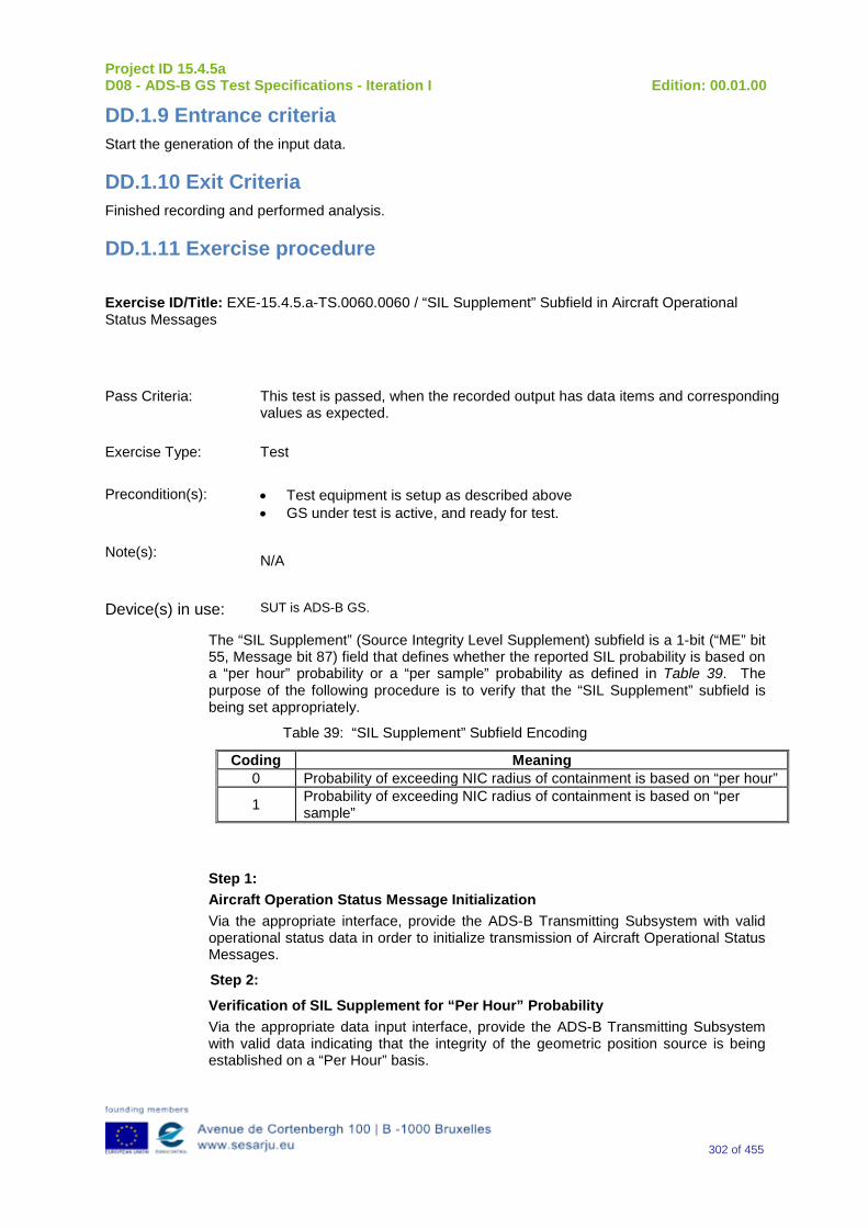
Project ID 15.4.5a D08 - ADS-B GS Test Specifications - Iteration I Edition: 00.01.00
302 of 455
DD.1.9 Entrance criteria Start the generation of the input data.
DD.1.10 Exit Criteria Finished recording and performed analysis.
DD.1.11 Exercise procedure
Exercise ID/Title: EXE-15.4.5.a-TS.0060.0060 / “SIL Supplement” Subfield in Aircraft Operational Status Messages
Pass Criteria: This test is passed, when the recorded output has data items and corresponding values as expected.
Exercise Type: Test
Precondition(s): • Test equipment is setup as described above • GS under test is active, and ready for test.
Note(s): N/A
Device(s) in use: SUT is ADS-B GS.
The “SIL Supplement” (Source Integrity Level Supplement) subfield is a 1-bit (“ME” bit 55, Message bit 87) field that defines whether the reported SIL probability is based on a “per hour” probability or a “per sample” probability as defined in Table 39. The purpose of the following procedure is to verify that the “SIL Supplement” subfield is being set appropriately.
Table 39: “SIL Supplement” Subfield Encoding
Coding Meaning 0 Probability of exceeding NIC radius of containment is based on “per hour”
1 Probability of exceeding NIC radius of containment is based on “per sample”
Step 1: Aircraft Operation Status Message Initialization Via the appropriate interface, provide the ADS-B Transmitting Subsystem with valid operational status data in order to initialize transmission of Aircraft Operational Status Messages.
Step 2:
Verification of SIL Supplement for “Per Hour” Probability Via the appropriate data input interface, provide the ADS-B Transmitting Subsystem with valid data indicating that the integrity of the geometric position source is being established on a “Per Hour” basis.
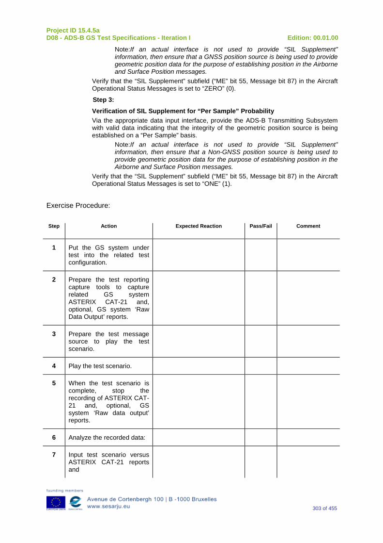
Project ID 15.4.5a D08 - ADS-B GS Test Specifications - Iteration I Edition: 00.01.00
303 of 455
Note:If an actual interface is not used to provide “SIL Supplement” information, then ensure that a GNSS position source is being used to provide geometric position data for the purpose of establishing position in the Airborne and Surface Position messages.
Verify that the “SIL Supplement” subfield (“ME” bit 55, Message bit 87) in the Aircraft Operational Status Messages is set to “ZERO” (0).
Step 3:
Verification of SIL Supplement for “Per Sample” Probability Via the appropriate data input interface, provide the ADS-B Transmitting Subsystem with valid data indicating that the integrity of the geometric position source is being established on a “Per Sample” basis.
Note:If an actual interface is not used to provide “SIL Supplement” information, then ensure that a Non-GNSS position source is being used to provide geometric position data for the purpose of establishing position in the Airborne and Surface Position messages.
Verify that the “SIL Supplement” subfield (“ME” bit 55, Message bit 87) in the Aircraft Operational Status Messages is set to “ONE” (1).
Exercise Procedure:
Step Action Expected Reaction Pass/Fail Comment
1 Put the GS system under test into the related test configuration.
2 Prepare the test reporting capture tools to capture related GS system ASTERIX CAT-21 and, optional, GS system ‘Raw Data Output’ reports.
3 Prepare the test message source to play the test scenario.
4 Play the test scenario.
5 When the test scenario is complete, stop the recording of ASTERIX CAT-21 and, optional, GS system ‘Raw data output’ reports.
6 Analyze the recorded data:
7 Input test scenario versus ASTERIX CAT-21 reports and
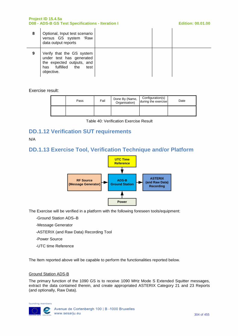
Project ID 15.4.5a D08 - ADS-B GS Test Specifications - Iteration I Edition: 00.01.00
304 of 455
8 Optional, Input test scenario versus GS system ‘Raw data output reports
9 Verify that the GS system under test has generated the expected outputs, and has fulfilled the test objective.
Exercise result:
Pass Fail Done By (Name, Organisation)
Configuration(s) during the exercise Date
Table 40: Verification Exercise Result
DD.1.12 Verification SUT requirements N/A
DD.1.13 Exercise Tool, Verification Technique and/or Platform
ADS-BGround Station
Power
ASTERIX(and Raw Data)
Recording
UTC Time Reference
RF Source(Message Generator)
The Exercise will be verified in a platform with the following foreseen tools/equipment:
-Ground Station ADS–B
-Message Generator
-ASTERIX (and Raw Data) Recording Tool
-Power Source
-UTC time Reference
The Item reported above will be capable to perform the functionalities reported below.
Ground Station ADS-B
The primary function of the 1090 GS is to receive 1090 MHz Mode S Extended Squitter messages, extract the data contained therein, and create appropriated ASTERIX Category 21 and 23 Reports (and optionally, Raw Data).
Project ID 15.4.5a D08 - ADS-B GS Test Specifications - Iteration I Edition: 00.01.00
305 of 455
Message Generator
The Messages Generator will be capable to generate the data coming from the Remote System (ADS–B Ground Station or 1090 Receiver) like:
•Target data stream with inside the information extracted by the ADS–B message (ASTERIX CAT 21 in the case of Ground Station or Raw Data in the case that remote system is a 1090 MHz Receiver).
•Operational Data Stream with inside the Remote System’s Operational Status Information (ASTERIX CAT 23 in the case of Ground Station or Raw Data in the case that remote system is a 1090 MHz Receiver).
UTC Time Reference
The UTC Time reference is the solution adopted in the Test Scenario in order to provide the Synchronization in the Ground Station by UTC Time.
ASTERIX Recording Equipment
The ASTERIX recording equipment will be capable to record all ASTERIX reports sent from the 1090 ES Ground Station.
DD.1.14 Verification Platform needs See section 3.5 Verification Platform Needs.
DD.1.15 Platform Configuration N/A
DD.1.16 Configuration(s) Identification of the Verification Platform N/A
DD.1.17 Links to other Verification Exercises N/A
DD.1.18 Representatively level/ limitations N/A
DD.2 Exercises Planning and management
DD.2.1 Activities N/A
DD.2.1.1 Preparatory activities Setup the tools/equipment listed in 3.5 and DD.1.13 in order to meet the Test Preconditions.
DD.2.1.2 Execution activities Play the scenario generating in the input the desired messages and record the relevant ASTERIX (and Raw Data) output.
Project ID 15.4.5a D08 - ADS-B GS Test Specifications - Iteration I Edition: 00.01.00
306 of 455
DD.2.1.3 Post execution activities The post execution activities will be mainly focused on the analysis of recorded ASTERIX reports (and Raw Data reports). The analysis shall be done in order to verify the right information propagation as requested in each Test Scenario.
DD.2.2 Human Resources N/A
DD.2.3 Responsibilities in the exercise N/A
DD.2.4 Training N/A
DD.2.5 Time planning N/A
DD.2.6 Risks N/A
DD.2.7 Errors and Observation handling N/A
DD.3 Analysis Specification
DD.3.1 Data collection methods The data collection during the test will be Qualitative. In fact after test execution the analysis of ASTERIX Data will be performed verifying that the values reported in the output are in line with the values generated in the input.
DD.3.2 Analysis method N/A
DD.3.3 Data logging requirements The data logging requirements for this scenario will foresee at least ASTERIX CAT 21 items.
Project ID 15.4.5a D08 - ADS-B GS Test Specifications - Iteration I Edition: 00.01.00
307 of 455
Appendix EE Verification Exercise EXE-15.04.05.a-TS.0060.0070 GS: “System Design Assurance” OM Code Subfield in Aircraft Operational Status Messages
EE.1 Exercise Scope and Justification
EE.1.1 Exercise Level The level of the exercise is functional.
EE.1.2 Exercise Type The type of the exercise is Test.
EE.1.3 Description of the system being addressed ADS – B Ground Station.
EE.1.4 Context of the verification exercise This document is applied to FAT (Factory acceptance Test).
EE.1.5 Required Datasets 1090MHz Extended Squitter Messages input and 1090GS ASTERIX output.
EE.1.6 Verification objectives Verify the Requirements related to the enhancement 1090ES Technology, more specifically, the following requirements:
OBJ-15.04.05.a-TS.0060.0061 The aim of this objective is to check that the ADS–B Surveillance System is capable to decode the ADS-B message, in order to extract the available information, in accordance with the introduced changes in the DO-260B standard.
OBJ-15.04.05.a-TS.0060.0063 The aim of this objective is to check that the ADS-B System ground surveillance domain is able to transform the introduced DO-260B changes into Standard ASTERIX Category 21 data items.
EE.1.7 Inputs 1090MHz Extended Squitter Messages.
EE.1.8 Outputs Recordings of ASTERIX CAT-21 and, optionally, GS system ‘Raw data output’ reports.
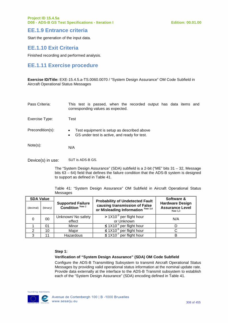
Project ID 15.4.5a D08 - ADS-B GS Test Specifications - Iteration I Edition: 00.01.00
308 of 455
EE.1.9 Entrance criteria Start the generation of the input data.
EE.1.10 Exit Criteria Finished recording and performed analysis.
EE.1.11 Exercise procedure
Exercise ID/Title: EXE-15.4.5.a-TS.0060.0070 / “System Design Assurance” OM Code Subfield in Aircraft Operational Status Messages
Pass Criteria: This test is passed, when the recorded output has data items and corresponding values as expected.
Exercise Type: Test
Precondition(s): • Test equipment is setup as described above • GS under test is active, and ready for test.
Note(s): N/A
Device(s) in use: SUT is ADS-B GS.
The “System Design Assurance” (SDA) subfield is a 2-bit (“ME” bits 31 – 32, Message bits 63 – 64) field that defines the failure condition that the ADS-B system is designed to support as defined in Table 41. Table 41: “System Design Assurance” OM Subfield in Aircraft Operational Status Messages
SDA Value Supported Failure
Condition Note 2
Probability of Undetected Fault causing transmission of False or Misleading Information Note 3,4
Software & Hardware Design Assurance Level
Note 1,3 (decimal) (binary)
0 00 Unknown/ No safety effect
> 1X10⁻³ per flight hour or Unknown N/A
1 01 Minor ≤ 1X10⁻³ per flight hour D 2 10 Major ≤ 1X10⁻⁵ per flight hour C 3 11 Hazardous ≤ 1X10⁻⁷ per flight hour B
Step 1: Verification of “System Design Assurance” (SDA) OM Code Subfield Configure the ADS-B Transmitting Subsystem to transmit Aircraft Operational Status Messages by providing valid operational status information at the nominal update rate. Provide data externally at the interface to the ADS-B Transmit subsystem to establish each of the “System Design Assurance” (SDA) encoding defined in Table 41.
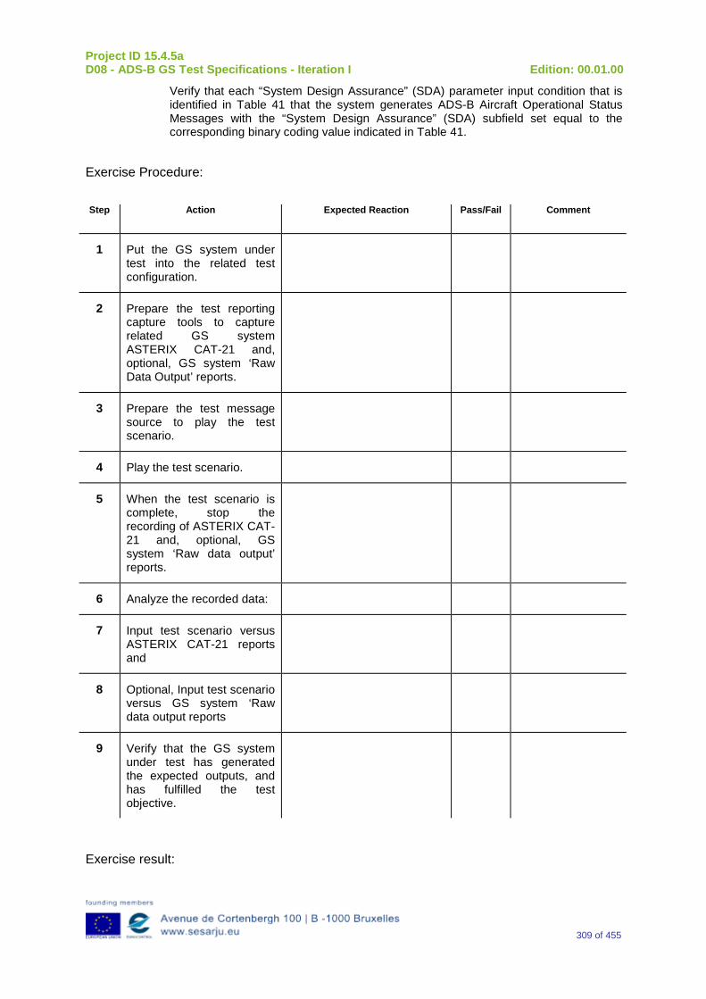
Project ID 15.4.5a D08 - ADS-B GS Test Specifications - Iteration I Edition: 00.01.00
309 of 455
Verify that each “System Design Assurance” (SDA) parameter input condition that is identified in Table 41 that the system generates ADS-B Aircraft Operational Status Messages with the “System Design Assurance” (SDA) subfield set equal to the corresponding binary coding value indicated in Table 41.
Exercise Procedure:
Step Action Expected Reaction Pass/Fail Comment
1 Put the GS system under test into the related test configuration.
2 Prepare the test reporting capture tools to capture related GS system ASTERIX CAT-21 and, optional, GS system ‘Raw Data Output’ reports.
3 Prepare the test message source to play the test scenario.
4 Play the test scenario.
5 When the test scenario is complete, stop the recording of ASTERIX CAT-21 and, optional, GS system ‘Raw data output’ reports.
6 Analyze the recorded data:
7 Input test scenario versus ASTERIX CAT-21 reports and
8 Optional, Input test scenario versus GS system ‘Raw data output reports
9 Verify that the GS system under test has generated the expected outputs, and has fulfilled the test objective.
Exercise result:

Project ID 15.4.5a D08 - ADS-B GS Test Specifications - Iteration I Edition: 00.01.00
310 of 455
Pass Fail Done By (Name, Organisation)
Configuration(s) during the exercise Date
Table 42: Verification Exercise Result
EE.1.12 Verification SUT requirements N/A
EE.1.13 Exercise Tool, Verification Technique and/or Platform
ADS-BGround Station
Power
ASTERIX(and Raw Data)
Recording
UTC Time Reference
RF Source(Message Generator)
The Exercise will be verified in a platform with the following foreseen tools/equipment:
-Ground Station ADS–B
-Message Generator
-ASTERIX (and Raw Data) Recording Tool
-Power Source
-UTC time Reference
The Item reported above will be capable to perform the functionalities reported below.
Ground Station ADS-B
The primary function of the 1090 GS is to receive 1090 MHz Mode S Extended Squitter messages, extract the data contained therein, and create appropriated ASTERIX Category 21 and 23 Reports (and optionally, Raw Data).
Message Generator
The Messages Generator will be capable to generate the data coming from the Remote System (ADS–B Ground Station or 1090 Receiver) like:
•Target data stream with inside the information extracted by the ADS–B message (ASTERIX CAT 21 in the case of Ground Station or Raw Data in the case that remote system is a 1090 MHz Receiver).
•Operational Data Stream with inside the Remote System’s Operational Status Information (ASTERIX CAT 23 in the case of Ground Station or Raw Data in the case that remote system is a 1090 MHz Receiver).
UTC Time Reference
The UTC Time reference is the solution adopted in the Test Scenario in order to provide the Synchronization in the Ground Station by UTC Time.
Project ID 15.4.5a D08 - ADS-B GS Test Specifications - Iteration I Edition: 00.01.00
311 of 455
ASTERIX Recording Equipment
The ASTERIX recording equipment will be capable to record all ASTERIX reports sent from the 1090 ES Ground Station.
EE.1.14 Verification Platform needs See section 3.5 Verification Platform Needs.
EE.1.15 Platform Configuration N/A
EE.1.16 Configuration(s) Identification of the Verification Platform N/A
EE.1.17 Links to other Verification Exercise N/A
EE.1.18 Representatively level/ limitations N/A
EE.2 Exercises Planning and management
EE.2.1 Activities N/A
EE.2.1.1 Preparatory activities Setup the tools/equipment listed in 3.5 and EE.1.13 in order to meet the Test Preconditions.
EE.2.1.2 Execution activities Play the scenario generating in the input the desired messages and record the relevant ASTERIX (and Raw Data) output.
EE.2.1.3 Post execution activities The post execution activities will be mainly focused on the analysis of recorded ASTERIX reports (and Raw Data reports). The analysis shall be done in order to verify the right information propagation as requested in each Test Scenario.
EE.2.2 Human Resources N/A
EE.2.3 Responsibilities in the exercise N/A
EE.2.4 Training N/A
Project ID 15.4.5a D08 - ADS-B GS Test Specifications - Iteration I Edition: 00.01.00
312 of 455
EE.2.5 Time planning N/A
EE.2.6 Risks N/A
EE.2.7 Errors and Observation handling N/A
EE.3 Analysis Specification
EE.3.1 Data collection methods The data collection during the test will be Qualitative. In fact after test execution the analysis of ASTERIX Data will be performed verifying that the values reported in the output are in line with the values generated in the input.
EE.3.2 Analysis method N/A
EE.3.3 Data logging requirements The data logging requirements for this scenario will foresee at least ASTERIX CAT 21 items.

Project ID 15.4.5a D08 - ADS-B GS Test Specifications - Iteration I Edition: 00.01.00
313 of 455
Appendix FF Verification Exercise EXE-15.04.05.a-TS.0060.0080 GS: “1090ES IN” CC Code Subfield in Aircraft Operational Status Messages
FF.1 Exercise Scope and Justification
FF.1.1 Exercise Level The level of the exercise is functional.
FF.1.2 Exercise Type The type of the exercise is Test.
FF.1.3 Description of the system being addressed ADS – B Ground Station.
FF.1.4 Context of the verification exercise This document is applied to FAT (Factory acceptance Test).
FF.1.5 Required Datasets 1090MHz Extended Squitter Messages input and 1090GS ASTERIX output.
FF.1.6 Verification objectives Verify the Requirements related to the enhancement 1090ES Technology, more specifically, the following requirements:
OBJ-15.04.05.a-TS.0060.0061 The aim of this objective is to check that the ADS–B Surveillance System is capable to decode the ADS-B message, in order to extract the available information, in accordance with the introduced changes in the DO-260B standard.
OBJ-15.04.05.a-TS.0060.0063 The aim of this objective is to check that the ADS-B System ground surveillance domain is able to transform the introduced DO-260B changes into Standard ASTERIX Category 21 data items.
FF.1.7 Inputs 1090MHz Extended Squitter Messages.
FF.1.8 Outputs Recordings of ASTERIX CAT-21 and, optionally, GS system ‘Raw data output’ reports.
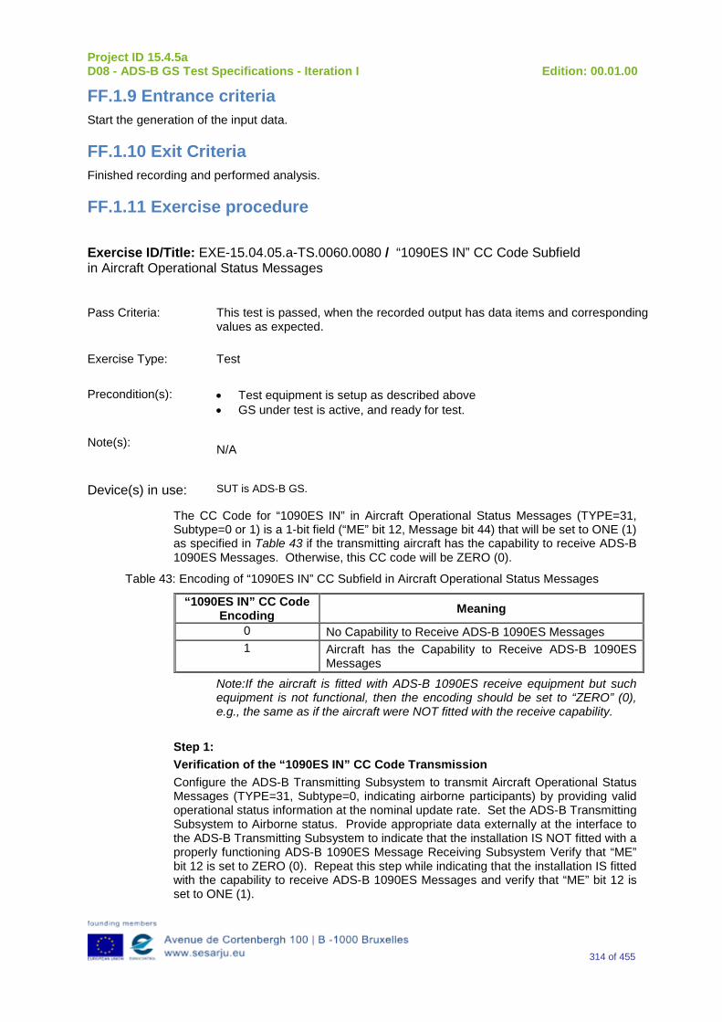
Project ID 15.4.5a D08 - ADS-B GS Test Specifications - Iteration I Edition: 00.01.00
314 of 455
FF.1.9 Entrance criteria Start the generation of the input data.
FF.1.10 Exit Criteria Finished recording and performed analysis.
FF.1.11 Exercise procedure
Exercise ID/Title: EXE-15.04.05.a-TS.0060.0080 / “1090ES IN” CC Code Subfield in Aircraft Operational Status Messages
Pass Criteria: This test is passed, when the recorded output has data items and corresponding
values as expected.
Exercise Type: Test
Precondition(s): • Test equipment is setup as described above • GS under test is active, and ready for test.
Note(s): N/A
Device(s) in use: SUT is ADS-B GS.
The CC Code for “1090ES IN” in Aircraft Operational Status Messages (TYPE=31, Subtype=0 or 1) is a 1-bit field (“ME” bit 12, Message bit 44) that will be set to ONE (1) as specified in Table 43 if the transmitting aircraft has the capability to receive ADS-B 1090ES Messages. Otherwise, this CC code will be ZERO (0).
Table 43: Encoding of “1090ES IN” CC Subfield in Aircraft Operational Status Messages
“1090ES IN” CC Code Encoding Meaning
0 No Capability to Receive ADS-B 1090ES Messages 1 Aircraft has the Capability to Receive ADS-B 1090ES
Messages
Note:If the aircraft is fitted with ADS-B 1090ES receive equipment but such equipment is not functional, then the encoding should be set to “ZERO” (0), e.g., the same as if the aircraft were NOT fitted with the receive capability.
Step 1: Verification of the “1090ES IN” CC Code Transmission Configure the ADS-B Transmitting Subsystem to transmit Aircraft Operational Status Messages (TYPE=31, Subtype=0, indicating airborne participants) by providing valid operational status information at the nominal update rate. Set the ADS-B Transmitting Subsystem to Airborne status. Provide appropriate data externally at the interface to the ADS-B Transmitting Subsystem to indicate that the installation IS NOT fitted with a properly functioning ADS-B 1090ES Message Receiving Subsystem Verify that “ME” bit 12 is set to ZERO (0). Repeat this step while indicating that the installation IS fitted with the capability to receive ADS-B 1090ES Messages and verify that “ME” bit 12 is set to ONE (1).
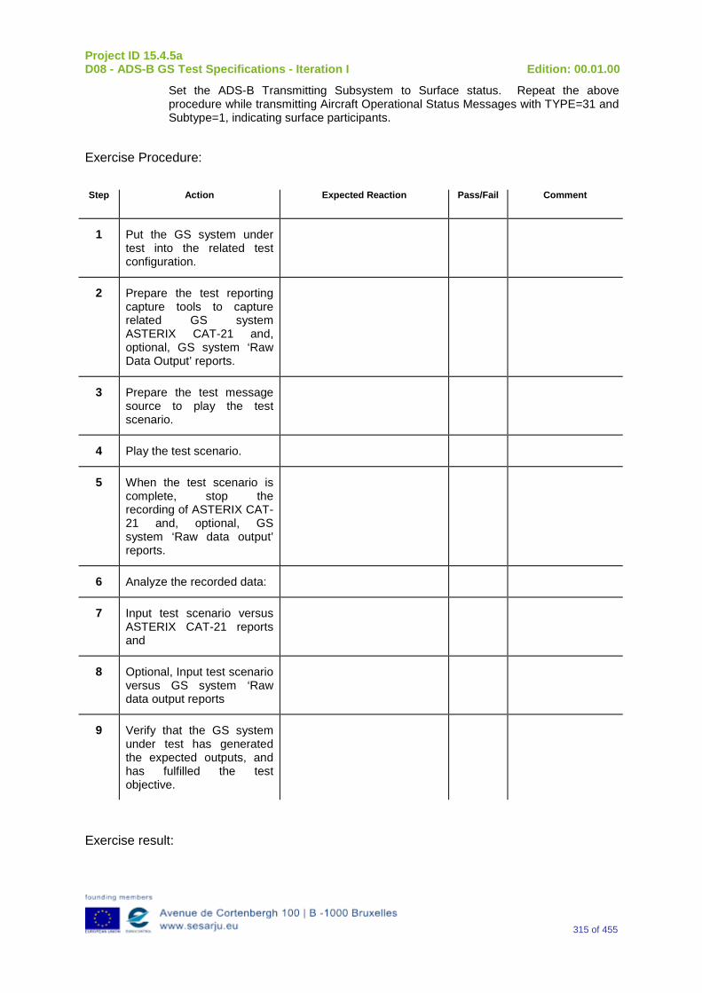
Project ID 15.4.5a D08 - ADS-B GS Test Specifications - Iteration I Edition: 00.01.00
315 of 455
Set the ADS-B Transmitting Subsystem to Surface status. Repeat the above procedure while transmitting Aircraft Operational Status Messages with TYPE=31 and Subtype=1, indicating surface participants.
Exercise Procedure:
Step Action Expected Reaction Pass/Fail Comment
1 Put the GS system under test into the related test configuration.
2 Prepare the test reporting capture tools to capture related GS system ASTERIX CAT-21 and, optional, GS system ‘Raw Data Output’ reports.
3 Prepare the test message source to play the test scenario.
4 Play the test scenario.
5 When the test scenario is complete, stop the recording of ASTERIX CAT-21 and, optional, GS system ‘Raw data output’ reports.
6 Analyze the recorded data:
7 Input test scenario versus ASTERIX CAT-21 reports and
8 Optional, Input test scenario versus GS system ‘Raw data output reports
9 Verify that the GS system under test has generated the expected outputs, and has fulfilled the test objective.
Exercise result:

Project ID 15.4.5a D08 - ADS-B GS Test Specifications - Iteration I Edition: 00.01.00
316 of 455
Pass Fail Done By (Name, Organisation)
Configuration(s) during the exercise Date
Table 44: Verification Exercise Result
FF.1.12 Verification SUT requirements N/A
FF.1.13 Exercise Tool, Verification Technique and/or Platform
ADS-BGround Station
Power
ASTERIX(and Raw Data)
Recording
UTC Time Reference
RF Source(Message Generator)
The Exercise will be verified in a platform with the following foreseen tools/equipment:
-Ground Station ADS–B
-Message Generator
-ASTERIX (and Raw Data) Recording Tool
-Power Source
-UTC time Reference
The Item reported above will be capable to perform the functionalities reported below.
Ground Station ADS-B
The primary function of the 1090 GS is to receive 1090 MHz Mode S Extended Squitter messages, extract the data contained therein, and create appropriated ASTERIX Category 21 and 23 Reports (and optionally, Raw Data).
Message Generator
The Messages Generator will be capable to generate the data coming from the Remote System (ADS–B Ground Station or 1090 Receiver) like:
•Target data stream with inside the information extracted by the ADS–B message (ASTERIX CAT 21 in the case of Ground Station or Raw Data in the case that remote system is a 1090 MHz Receiver).
•Operational Data Stream with inside the Remote System’s Operational Status Information (ASTERIX CAT 23 in the case of Ground Station or Raw Data in the case that remote system is a 1090 MHz Receiver).
UTC Time Reference
Project ID 15.4.5a D08 - ADS-B GS Test Specifications - Iteration I Edition: 00.01.00
317 of 455
The UTC Time reference is the solution adopted in the Test Scenario in order to provide the Synchronization in the Ground Station by UTC Time.
ASTERIX Recording Equipment
The ASTERIX recording equipment will be capable to record all ASTERIX reports sent from the 1090 ES Ground Station.
FF.1.14 Verification Platform needs See section 3.5 Verification Platform Needs.
FF.1.15 Platform Configuration N/A
FF.1.16 Configuration(s) Identification of the Verification Platform N/A
FF.1.17 Links to other Verification Exercises N/A
FF.1.18 Representatively level/ limitations N/A
FF.2 Exercises Planning and management
FF.2.1 Activities N/A
FF.2.1.1 Preparatory activities Setup the tools/equipment listed in 3.5 and FF.1.13 in order to meet the Test Preconditions.
FF.2.1.2 Execution activities Play the scenario generating in the input the desired messages and record the relevant ASTERIX (and Raw Data) output.
FF.2.1.3 Post execution activities The post execution activities will be mainly focused on the analysis of recorded ASTERIX reports (and Raw Data reports). The analysis shall be done in order to verify the right information propagation as requested in each Test Scenario.
FF.2.2 Human Resources N/A
FF.2.3 Responsibilities in the exercise N/A
Project ID 15.4.5a D08 - ADS-B GS Test Specifications - Iteration I Edition: 00.01.00
318 of 455
FF.2.4 Training N/A
FF.2.5 Time planning N/A
FF.2.6 Risks N/A
FF.2.7 Errors and Observation handling N/A
FF.3 Analysis Specification
FF.3.1 Data collection methods The data collection during the test will be Qualitative. In fact after test execution the analysis of ASTERIX Data will be performed verifying that the values reported in the output are in line with the values generated in the input.
FF.3.2 Analysis method N/A
FF.3.3 Data logging requirements The data logging requirements for this scenario will foresee at least ASTERIX CAT 21 items.
Project ID 15.4.5a D08 - ADS-B GS Test Specifications - Iteration I Edition: 00.01.00
319 of 455
Appendix GG Verification Exercise EXE-15.04.05.a-TS.0060.0090 GS: “UAT IN” CC Code Subfield in Aircraft Operational Status Messages
GG.1 Exercise Scope and Justification
GG.1.1 Exercise Level The level of the exercise is functional.
GG.1.2 Exercise Type The type of the exercise is Test.
GG.1.3 Description of the system being addressed ADS – B Ground Station.
GG.1.4 Context of the verification exercise This document is applied to FAT (Factory acceptance Test).
GG.1.5Required Datasets 1090MHz Extended Squitter Messages input and 1090GS ASTERIX output.
GG.1.6 Verification objectives Verify the Requirements related to the enhancement 1090ES Technology, more specifically, the following requirements:
OBJ-15.04.05.a-TS.0060.0061 The aim of this objective is to check that the ADS–B Surveillance System is capable to decode the ADS-B message, in order to extract the available information, in accordance with the introduced changes in the DO-260B standard.
OBJ-15.04.05.a-TS.0060.0063 The aim of this objective is to check that the ADS-B System ground surveillance domain is able to transform the introduced DO-260B changes into Standard ASTERIX Category 21 data items.
GG.1.7 Inputs 1090MHz Extended Squitter Messages.
GG.1.8 Outputs Recordings of ASTERIX CAT-21 and, optionally, GS system ‘Raw data output’ reports.
Project ID 15.4.5a D08 - ADS-B GS Test Specifications - Iteration I Edition: 00.01.00
320 of 455
GG.1.9 Entrance criteria Start the generation of the input data.
GG.1.10 Exit Criteria Finished recording and performed analysis.
GG.1.11 Exercise procedure
Exercise ID/Title: EXE-15.4.5.a-TS.0060.0090 /“UAT IN” CC Code Subfield in Aircraft Operational Status Messages
Pass Criteria: This test is passed, when the recorded output has data items and corresponding values as expected.
Exercise Type: Test
Precondition(s): • Test equipment is setup as described above • GS under test is active, and ready for test.
Note(s): N/A
Device(s) in use: SUT is ADS-B GS.
The “UAT IN” CC Code subfield (“ME” bit 19, Message bit 51, TYPE=31, Subtype=0, for airborne participants AND “ME” Bit 16, Message bit 48, TYPE=31, Subtype=1 for surface participants) in ADS-B Aircraft Operational Status Messages denotes whether the aircraft is equipped with the capability to receive ADS-B UAT Messages. The coding of “UAT IN” CC Code subfield is specified in Table 45. Table 45: Encoding of “UAT IN” CC Subfield in Aircraft Operational Status Messages.
“UAT IN” CC Code Encoding Meaning
0 No Capability to Receive ADS-B UAT Messages 1 Aircraft has the Capability to Receive ADS-B UAT
Messages
Step 1: Verification of “UAT IN” CC Code Transmission
a. Configure the ADS-B Transmitting Subsystem to transmit Aircraft Operational Status Messages by providing valid operational status information at the nominal update rate. Provide appropriate data externally at the interface to the ADS-B Transmitting Subsystem to indicate that the installation IS fitted with a properly functioning ADS-B UAT Receiving Subsystem. Set the ADS-B Transmitting Subsystem to Airborne status. Verify that “ME” bit 19 (Message bit 51) is set to ONE (1).
b. Repeat Step 1.a while indicating that the aircraft has NO UAT IN Receive capability, and verify that “ME” bit 19 (Message bit 51) is set to ZERO (0).
Project ID 15.4.5a D08 - ADS-B GS Test Specifications - Iteration I Edition: 00.01.00
321 of 455
c. Repeat Step 1.a after setting the ADS-B Transmitting Subsystem to Surface status, and verify that “ME” bit 16 (Message bit 48) is set to ONE (1).
d. Repeat Step 1.b after setting the ADS-B Transmitting Subsystem to Surface status and verify the “ME” bit 16 (Message bit 48) is set to ZERO (0).
Exercise Procedure:
Step Action Expected Reaction Pass/Fail Comment
1 Put the GS system under test into the related test configuration.
2 Prepare the test reporting capture tools to capture related GS system ASTERIX CAT-21 and, optional, GS system ‘Raw Data Output’ reports.
3 Prepare the test message source to play the test scenario.
4 Play the test scenario.
5 When the test scenario is complete, stop the recording of ASTERIX CAT-21 and, optional, GS system ‘Raw data output’ reports.
6 Analyze the recorded data:
7 Input test scenario versus ASTERIX CAT-21 reports and
8 Optional, Input test scenario versus GS system ‘Raw data output reports
9 Verify that the GS system under test has generated the expected outputs, and has fulfilled the test objective.
Exercise result:
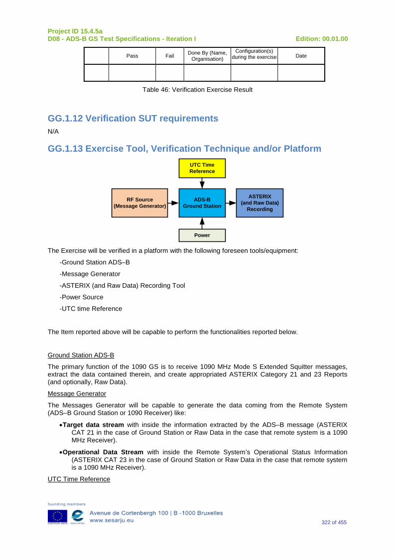
Project ID 15.4.5a D08 - ADS-B GS Test Specifications - Iteration I Edition: 00.01.00
322 of 455
Pass Fail Done By (Name, Organisation)
Configuration(s) during the exercise Date
Table 46: Verification Exercise Result
GG.1.12 Verification SUT requirements N/A
GG.1.13 Exercise Tool, Verification Technique and/or Platform
ADS-BGround Station
Power
ASTERIX(and Raw Data)
Recording
UTC Time Reference
RF Source(Message Generator)
The Exercise will be verified in a platform with the following foreseen tools/equipment:
-Ground Station ADS–B
-Message Generator
-ASTERIX (and Raw Data) Recording Tool
-Power Source
-UTC time Reference
The Item reported above will be capable to perform the functionalities reported below.
Ground Station ADS-B
The primary function of the 1090 GS is to receive 1090 MHz Mode S Extended Squitter messages, extract the data contained therein, and create appropriated ASTERIX Category 21 and 23 Reports (and optionally, Raw Data).
Message Generator
The Messages Generator will be capable to generate the data coming from the Remote System (ADS–B Ground Station or 1090 Receiver) like:
•Target data stream with inside the information extracted by the ADS–B message (ASTERIX CAT 21 in the case of Ground Station or Raw Data in the case that remote system is a 1090 MHz Receiver).
•Operational Data Stream with inside the Remote System’s Operational Status Information (ASTERIX CAT 23 in the case of Ground Station or Raw Data in the case that remote system is a 1090 MHz Receiver).
UTC Time Reference
Project ID 15.4.5a D08 - ADS-B GS Test Specifications - Iteration I Edition: 00.01.00
323 of 455
The UTC Time reference is the solution adopted in the Test Scenario in order to provide the Synchronization in the Ground Station by UTC Time.
ASTERIX Recording Equipment
The ASTERIX recording equipment will be capable to record all ASTERIX reports sent from the 1090 ES Ground Station.
GG.1.14 Verification Platform needs See section 3.5 Verification Platform Needs.
GG.1.15 Platform Configuration N/A
GG.1.16 Configuration(s) Identification of the Verification Platform N/A
GG.1.17 Links to other Verification Exercise N/A
GG.1.18 Representatively level/ limitations N/A
GG.2 Exercises Planning and management
GG.2.1 Activities N/A
GG.2.1.1 Preparatory activities Setup the tools/equipment listed in 3.5 and GG.1.13 in order to meet the Test Preconditions.
GG.2.1.2 Execution activities Play the scenario generating in the input the desired messages and record the relevant ASTERIX (and Raw Data) output.
GG.2.1.3 Post execution activities The post execution activities will be mainly focused on the analysis of recorded ASTERIX reports (and Raw Data reports). The analysis shall be done in order to verify the right information propagation as requested in each Test Scenario.
GG.2.2 Human Resources N/A
GG.2.3 Responsibilities in the exercise N/A
Project ID 15.4.5a D08 - ADS-B GS Test Specifications - Iteration I Edition: 00.01.00
324 of 455
GG.2.4 Training N/A
GG.2.5 Time planning N/A
GG.2.6 Risks N/A
GG.2.7 Errors and Observation handling N/A
GG.3 Analysis Specification
GG.3.1 Data collection methods The data collection during the test will be Qualitative. In fact after test execution the analysis of ASTERIX Data will be performed verifying that the values reported in the output are in line with the values generated in the input.
GG.3.2 Analysis method N/A
GG.3.3 Data logging requirements The data logging requirements for this scenario will foresee at least ASTERIX CAT 21 items.
Project ID 15.4.5a D08 - ADS-B GS Test Specifications - Iteration I Edition: 00.01.00
325 of 455
Appendix HH Verification Exercise EXE-15.04.05.a-TS.0060.0100 GS: “NIC Supplement-B” Subfield in ADS-B Airborne Position Messages
HH.1 Exercise Scope and Justification
HH.1.1 Exercise Level The level of the exercise is functional.
HH.1.2 Exercise Type The type of the exercise is Test.
HH.1.3 Description of the system being addressed ADS – B Ground Station.
HH.1.4 Context of the verification exercise This document is applied to FAT (Factory acceptance Test).
HH.1.5 Required Datasets 1090MHz Extended Squitter Messages input and 1090GS ASTERIX output.
HH.1.6 Verification objectives Verify the Requirements related to the enhancement 1090ES Technology, more specifically, the following requirements:
OBJ-15.04.05.a-TS.0060.0061 The aim of this objective is to check that the ADS–B Surveillance System is capable to decode the ADS-B message, in order to extract the available information, in accordance with the introduced changes in the DO-260B standard.
OBJ-15.04.05.a-TS.0060.0063 The aim of this objective is to check that the ADS-B System ground surveillance domain is able to transform the introduced DO-260B changes into Standard ASTERIX Category 21 data items.
HH.1.7 Inputs 1090MHz Extended Squitter Messages.
HH.1.8 Outputs Recordings of ASTERIX CAT-21 and, optionally, GS system ‘Raw data output’ reports.
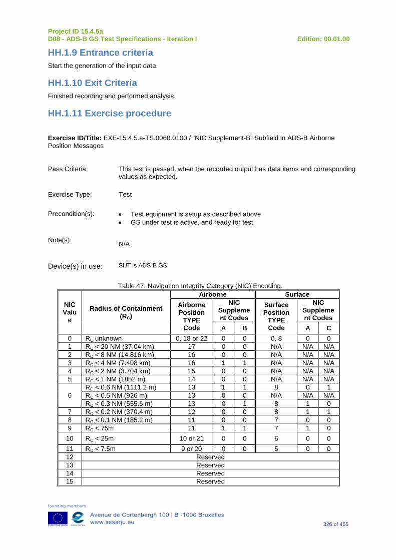
Project ID 15.4.5a D08 - ADS-B GS Test Specifications - Iteration I Edition: 00.01.00
326 of 455
HH.1.9 Entrance criteria Start the generation of the input data.
HH.1.10 Exit Criteria Finished recording and performed analysis.
HH.1.11 Exercise procedure
Exercise ID/Title: EXE-15.4.5.a-TS.0060.0100 / “NIC Supplement-B” Subfield in ADS-B Airborne Position Messages
Pass Criteria: This test is passed, when the recorded output has data items and corresponding values as expected.
Exercise Type: Test
Precondition(s): • Test equipment is setup as described above • GS under test is active, and ready for test.
Note(s): N/A
Device(s) in use: SUT is ADS-B GS.
Table 47: Navigation Integrity Category (NIC) Encoding.
NIC Valu
e Radius of Containment
(RC)
Airborne Surface Airborne Position
TYPE Code
NIC Supplement Codes
Surface Position
TYPE Code
NIC Supplement Codes
A B A C 0 RC unknown 0, 18 or 22 0 0 0, 8 0 0 1 RC < 20 NM (37.04 km) 17 0 0 N/A N/A N/A 2 RC < 8 NM (14.816 km) 16 0 0 N/A N/A N/A 3 RC < 4 NM (7.408 km) 16 1 1 N/A N/A N/A 4 RC < 2 NM (3.704 km) 15 0 0 N/A N/A N/A 5 RC < 1 NM (1852 m) 14 0 0 N/A N/A N/A
6 RC < 0.6 NM (1111.2 m) 13 1 1 8 0 1 RC < 0.5 NM (926 m) 13 0 0 N/A N/A N/A RC < 0.3 NM (555.6 m) 13 0 1 8 1 0
7 RC < 0.2 NM (370.4 m) 12 0 0 8 1 1 8 RC < 0.1 NM (185.2 m) 11 0 0 7 0 0 9 RC < 75m 11 1 1 7 1 0
10 RC < 25m 10 or 21 0 0 6 0 0 11 RC < 7.5m 9 or 20 0 0 5 0 0 12 Reserved 13 Reserved 14 Reserved 15 Reserved
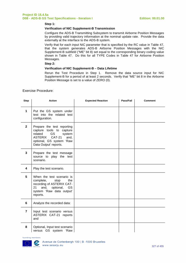
Project ID 15.4.5a D08 - ADS-B GS Test Specifications - Iteration I Edition: 00.01.00
327 of 455
Step 1: Verification of NIC Supplement-B Transmission Configure the ADS-B Transmitting Subsystem to transmit Airborne Position Messages by providing valid trajectory information at the nominal update rate. Provide the data externally at the interface to the ADS-B system. Verify that for each input NIC parameter that is specified by the RC value in Table 47, that the system generates ADS-B Airborne Position Messages with the NIC Supplement-B subfield (“ME” bit 8) set equal to the corresponding binary coding value shown in Table 47. Do this for all TYPE Codes in Table 47 for Airborne Position Messages. Step 2: Verification of NIC Supplement-B − Data Lifetime Rerun the Test Procedure in Step 1. Remove the data source input for NIC Supplement-B for a period of at least 2 seconds. Verify that “ME” bit 8 in the Airborne Position Message is set to a value of ZERO (0).
Exercise Procedure:
Step Action Expected Reaction Pass/Fail Comment
1 Put the GS system under test into the related test configuration.
2 Prepare the test reporting capture tools to capture related GS system ASTERIX CAT-21 and, optional, GS system ‘Raw Data Output’ reports.
3 Prepare the test message source to play the test scenario.
4 Play the test scenario.
5 When the test scenario is complete, stop the recording of ASTERIX CAT-21 and, optional, GS system ‘Raw data output’ reports.
6 Analyze the recorded data:
7 Input test scenario versus ASTERIX CAT-21 reports and
8 Optional, Input test scenario versus GS system ‘Raw

Project ID 15.4.5a D08 - ADS-B GS Test Specifications - Iteration I Edition: 00.01.00
328 of 455
data output reports
9 Verify that the GS system under test has generated the expected outputs, and has fulfilled the test objective.
Exercise result:
Pass Fail Done By (Name, Organisation)
Configuration(s) during the exercise Date
Table 48: Verification Exercise Result
HH.1.12 Verification SUT requirements N/A
HH.1.13 Exercise Tool, Verification Technique and/or Platform
ADS-BGround Station
Power
ASTERIX(and Raw Data)
Recording
UTC Time Reference
RF Source(Message Generator)
The Exercise will be verified in a platform with the following foreseen tools/equipment:
-Ground Station ADS–B
-Message Generator
-ASTERIX (and Raw Data) Recording Tool
-Power Source
-UTC time Reference
The Item reported above will be capable to perform the functionalities reported below.
Ground Station ADS-B
The primary function of the 1090 GS is to receive 1090 MHz Mode S Extended Squitter messages, extract the data contained therein, and create appropriated ASTERIX Category 21 and 23 Reports (and optionally, Raw Data).
Message Generator
The Messages Generator will be capable to generate the data coming from the Remote System (ADS–B Ground Station or 1090 Receiver) like:
Project ID 15.4.5a D08 - ADS-B GS Test Specifications - Iteration I Edition: 00.01.00
329 of 455
•Target data stream with inside the information extracted by the ADS–B message (ASTERIX CAT 21 in the case of Ground Station or Raw Data in the case that remote system is a 1090 MHz Receiver).
•Operational Data Stream with inside the Remote System’s Operational Status Information (ASTERIX CAT 23 in the case of Ground Station or Raw Data in the case that remote system is a 1090 MHz Receiver).
UTC Time Reference
The UTC Time reference is the solution adopted in the Test Scenario in order to provide the Synchronization in the Ground Station by UTC Time.
ASTERIX Recording Equipment
The ASTERIX recording equipment will be capable to record all ASTERIX reports sent from the 1090 ES Ground Station.
HH.1.14 Verification Platform needs See section 3.5 Verification Platform Needs.
HH.1.15 Platform Configuration N/A
HH.1.16 Configuration(s) Identification of the Verification Platform N/A
HH.1.17 Links to other Verification Exercises N/A
HH.1.18 Representatively level/ limitations N/A
HH.2 Exercises Planning and management
HH.2.1 Activities N/A
HH.2.1.1 Preparatory activities Setup the tools/equipment listed in 3.5 and HH.1.13 in order to meet the Test Preconditions.
HH.2.1.2 Execution activities Play the scenario generating in the input the desired messages and record the relevant ASTERIX (and Raw Data) output.
HH.2.1.3 Post execution activities The post execution activities will be mainly focused on the analysis of recorded ASTERIX reports (and Raw Data reports). The analysis shall be done in order to verify the right information propagation as requested in each Test Scenario.

Project ID 15.4.5a D08 - ADS-B GS Test Specifications - Iteration I Edition: 00.01.00
330 of 455
HH.2.2 Human Resources N/A
HH.2.3 Responsibilities in the exercise N/A
HH.2.4 Training N/A
HH.2.5 Time planning N/A
HH.2.6 Risks N/A
HH.2.7 Errors and Observation handling N/A
HH.3 Analysis Specification
HH.3.1 Data collection methods The data collection during the test will be Qualitative. In fact after test execution the analysis of ASTERIX Data will be performed verifying that the values reported in the output are in line with the values generated in the input.
HH.3.2 Analysis method N/A
HH.3.3 Data logging requirements The data logging requirements for this scenario will foresee at least ASTERIX CAT 21 items.
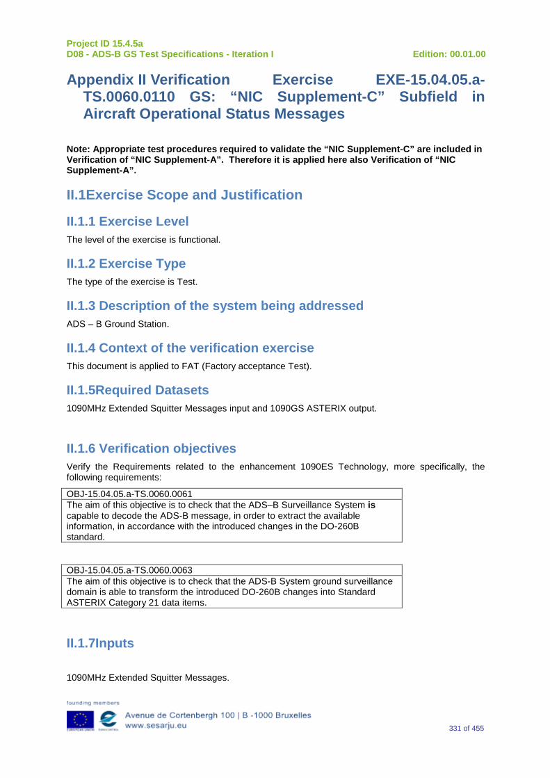
Project ID 15.4.5a D08 - ADS-B GS Test Specifications - Iteration I Edition: 00.01.00
331 of 455
Appendix II Verification Exercise EXE-15.04.05.a-TS.0060.0110 GS: “NIC Supplement-C” Subfield in Aircraft Operational Status Messages
Note: Appropriate test procedures required to validate the “NIC Supplement-C” are included in Verification of “NIC Supplement-A”. Therefore it is applied here also Verification of “NIC Supplement-A”.
II.1Exercise Scope and Justification
II.1.1 Exercise Level The level of the exercise is functional.
II.1.2 Exercise Type The type of the exercise is Test.
II.1.3 Description of the system being addressed ADS – B Ground Station.
II.1.4 Context of the verification exercise This document is applied to FAT (Factory acceptance Test).
II.1.5Required Datasets 1090MHz Extended Squitter Messages input and 1090GS ASTERIX output.
II.1.6 Verification objectives Verify the Requirements related to the enhancement 1090ES Technology, more specifically, the following requirements:
OBJ-15.04.05.a-TS.0060.0061 The aim of this objective is to check that the ADS–B Surveillance System is capable to decode the ADS-B message, in order to extract the available information, in accordance with the introduced changes in the DO-260B standard.
OBJ-15.04.05.a-TS.0060.0063 The aim of this objective is to check that the ADS-B System ground surveillance domain is able to transform the introduced DO-260B changes into Standard ASTERIX Category 21 data items.
II.1.7Inputs
1090MHz Extended Squitter Messages.
Project ID 15.4.5a D08 - ADS-B GS Test Specifications - Iteration I Edition: 00.01.00
332 of 455
II.1.8Outputs Recordings of ASTERIX CAT-21 and, optionally, GS system ‘Raw data output’ reports.
II.1.9 Entrance criteria Start the generation of the input data.
II.1.10 Exit Criteria Finished recording and performed analysis.
II.1.11 Exercise procedure
Exercise ID/Title: EXE-15.4.5.a-TS.0060.0150 / “NIC Supplement-C” Subfield in Aircraft Operational Status Messages Pass Criteria: This test is passed, when the recorded output has data items and corresponding
values as expected.
Exercise Type: Test
Precondition(s): • Test equipment is setup as described above • GS under test is active, and ready for test.
Note(s): N/A
Device(s) in use: SUT is ADS-B GS.
The NIC Supplement-A subfield in the Aircraft Operational Status Message is a 1-bit subfield (“ME” bit 44, Message bit 76) that, together with the TYPE subfield in Airborne Position and Surface Position Messages, is used to encode the Navigation Integrity Category (NIC) of the transmitting ADS-B participant. Table 49 lists the possible NIC codes and the values of the TYPE Code subfield of the Airborne and Surface Position Messages, and the NIC Supplement-A, NIC Supplement-B and NIC Supplement-C subfield values that are used to encode those NIC codes in messages on the 1090 MHz ADS-B data link.
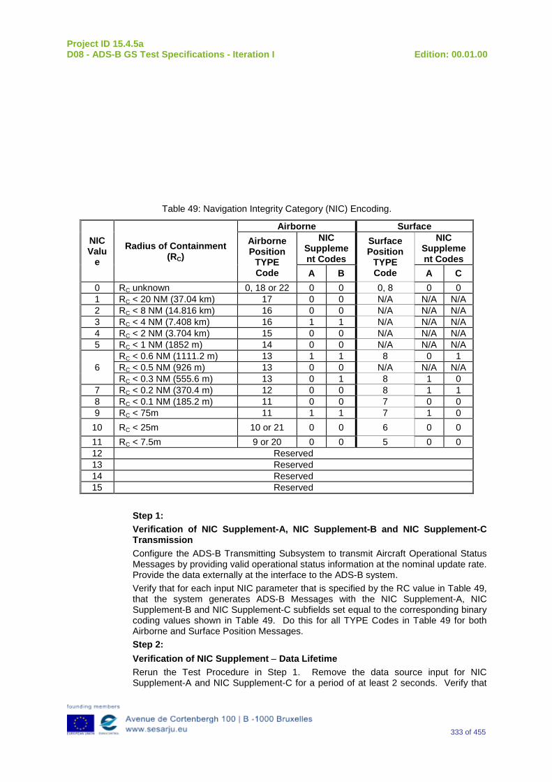
Project ID 15.4.5a D08 - ADS-B GS Test Specifications - Iteration I Edition: 00.01.00
333 of 455
Table 49: Navigation Integrity Category (NIC) Encoding.
NIC Valu
e Radius of Containment
(RC)
Airborne Surface Airborne Position
TYPE Code
NIC Supplement Codes
Surface Position
TYPE Code
NIC Supplement Codes
A B A C 0 RC unknown 0, 18 or 22 0 0 0, 8 0 0 1 RC < 20 NM (37.04 km) 17 0 0 N/A N/A N/A 2 RC < 8 NM (14.816 km) 16 0 0 N/A N/A N/A 3 RC < 4 NM (7.408 km) 16 1 1 N/A N/A N/A 4 RC < 2 NM (3.704 km) 15 0 0 N/A N/A N/A 5 RC < 1 NM (1852 m) 14 0 0 N/A N/A N/A
6 RC < 0.6 NM (1111.2 m) 13 1 1 8 0 1 RC < 0.5 NM (926 m) 13 0 0 N/A N/A N/A RC < 0.3 NM (555.6 m) 13 0 1 8 1 0
7 RC < 0.2 NM (370.4 m) 12 0 0 8 1 1 8 RC < 0.1 NM (185.2 m) 11 0 0 7 0 0 9 RC < 75m 11 1 1 7 1 0
10 RC < 25m 10 or 21 0 0 6 0 0 11 RC < 7.5m 9 or 20 0 0 5 0 0 12 Reserved 13 Reserved 14 Reserved 15 Reserved
Step 1: Verification of NIC Supplement-A, NIC Supplement-B and NIC Supplement-C Transmission Configure the ADS-B Transmitting Subsystem to transmit Aircraft Operational Status Messages by providing valid operational status information at the nominal update rate. Provide the data externally at the interface to the ADS-B system. Verify that for each input NIC parameter that is specified by the RC value in Table 49, that the system generates ADS-B Messages with the NIC Supplement-A, NIC Supplement-B and NIC Supplement-C subfields set equal to the corresponding binary coding values shown in Table 49. Do this for all TYPE Codes in Table 49 for both Airborne and Surface Position Messages. Step 2: Verification of NIC Supplement − Data Lifetime Rerun the Test Procedure in Step 1. Remove the data source input for NIC Supplement-A and NIC Supplement-C for a period of at least 2 seconds. Verify that
Project ID 15.4.5a D08 - ADS-B GS Test Specifications - Iteration I Edition: 00.01.00
334 of 455
the NIC-Supplement-A in the Aircraft Operational Status Message, and the NIC Supplement-B in the Airborne Position Message are set to a value of ZERO (0). Set the system to On-the-Ground condition and repeat this Test Procedure and verify that both the NIC Supplement-A and NIC Supplement-C are set to ZERO (0).
Exercise Procedure:
Step Action Expected Reaction Pass/Fail Comment
1 Put the GS system under test into the related test configuration.
2 Prepare the test reporting capture tools to capture related GS system ASTERIX CAT-21 and, optional, GS system ‘Raw Data Output’ reports.
3 Prepare the test message source to play the test scenario.
4 Play the test scenario.
5 When the test scenario is complete, stop the recording of ASTERIX CAT-21 and, optional, GS system ‘Raw data output’ reports.
6 Analyze the recorded data:
7 Input test scenario versus ASTERIX CAT-21 reports and
8 Optional, Input test scenario versus GS system ‘Raw data output reports
9 Verify that the GS system under test has generated the expected outputs, and has fulfilled the test objective.
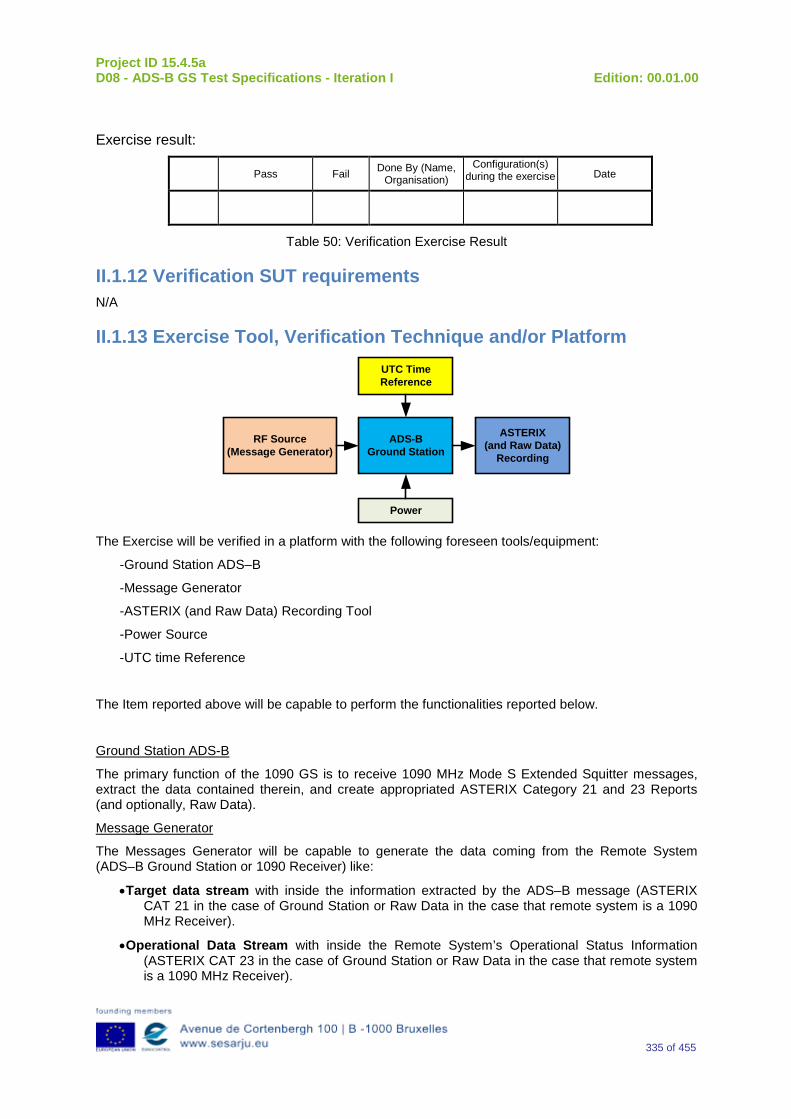
Project ID 15.4.5a D08 - ADS-B GS Test Specifications - Iteration I Edition: 00.01.00
335 of 455
Exercise result:
Pass Fail Done By (Name, Organisation)
Configuration(s) during the exercise Date
Table 50: Verification Exercise Result
II.1.12 Verification SUT requirements N/A
II.1.13 Exercise Tool, Verification Technique and/or Platform
ADS-BGround Station
Power
ASTERIX(and Raw Data)
Recording
UTC Time Reference
RF Source(Message Generator)
The Exercise will be verified in a platform with the following foreseen tools/equipment:
-Ground Station ADS–B
-Message Generator
-ASTERIX (and Raw Data) Recording Tool
-Power Source
-UTC time Reference
The Item reported above will be capable to perform the functionalities reported below.
Ground Station ADS-B
The primary function of the 1090 GS is to receive 1090 MHz Mode S Extended Squitter messages, extract the data contained therein, and create appropriated ASTERIX Category 21 and 23 Reports (and optionally, Raw Data).
Message Generator
The Messages Generator will be capable to generate the data coming from the Remote System (ADS–B Ground Station or 1090 Receiver) like:
•Target data stream with inside the information extracted by the ADS–B message (ASTERIX CAT 21 in the case of Ground Station or Raw Data in the case that remote system is a 1090 MHz Receiver).
•Operational Data Stream with inside the Remote System’s Operational Status Information (ASTERIX CAT 23 in the case of Ground Station or Raw Data in the case that remote system is a 1090 MHz Receiver).
Project ID 15.4.5a D08 - ADS-B GS Test Specifications - Iteration I Edition: 00.01.00
336 of 455
UTC Time Reference
The UTC Time reference is the solution adopted in the Test Scenario in order to provide the Synchronization in the Ground Station by UTC Time.
ASTERIX Recording Equipment
The ASTERIX recording equipment will be capable to record all ASTERIX reports sent from the 1090 ES Ground Station.
II.1.14 Verification Platform needs See section 3.5 Verification Platform Needs.
II.1.15 Platform Configuration N/A
II.1.16 Configuration(s) Identification of the Verification Platform N/A
II.1.17 Links to other Verification Exercise N/A
II.1.18 Representatively level/ limitations N/A
II.2 Exercises Planning and management
II.2.1 Activities N/A
II.2.1.1 Preparatory activities Setup the tools/equipment listed in 3.5 and II.1.13 in order to meet the Test Preconditions.
II.2.1.2 Execution activities Play the scenario generating in the input the desired messages and record the relevant ASTERIX (and Raw Data) output.
II.2.1.3 Post execution activities The post execution activities will be mainly focused on the analysis of recorded ASTERIX reports (and Raw Data reports). The analysis shall be done in order to verify the right information propagation as requested in each Test Scenario.
II.2.2 Human Resources N/A
II.2.3 Responsibilities in the exercise N/A
Project ID 15.4.5a D08 - ADS-B GS Test Specifications - Iteration I Edition: 00.01.00
337 of 455
II.2.4 Training N/A
II.2.5 Time planning N/A
II.2.6 Risks N/A
II.2.7 Errors and Observation handling N/A
II.3 Analysis Specification
II.3.1 Data collection methods The data collection during the test will be Qualitative. In fact after test execution the analysis of ASTERIX Data will be performed verifying that the values reported in the output are in line with the values generated in the input.
II.3.2Analysis method N/A
II.3.3 Data logging requirements The data logging requirements for this scenario will foresee at least ASTERIX CAT 21 items.
Project ID 15.4.5a D08 - ADS-B GS Test Specifications - Iteration I Edition: 00.01.00
338 of 455
Appendix JJ Verification Exercise EXE-15.04.05.a-TS.0060.0120 GS: “Aircraft/Vehicle Length and Width Code” Subfield in Aircraft Operational Status Messages
JJ.1 Exercise Scope and Justification
JJ.1.1 Exercise Level The level of the exercise is functional.
JJ.1.2 Exercise Type The type of the exercise is Test.
JJ.1.3 Description of the system being addressed ADS – B Ground Station.
JJ.1.4 Context of the verification exercise This document is applied to FAT (Factory acceptance Test).
JJ.1.5 Required Datasets 1090MHz Extended Squitter Messages input and 1090GS ASTERIX output.
JJ.1.6 Verification objectives Verify the Requirements related to the enhancement 1090ES Technology, more specifically, the following requirements:
OBJ-15.04.05.a-TS.0060.0061 The aim of this objective is to check that the ADS–B Surveillance System is capable to decode the ADS-B message, in order to extract the available information, in accordance with the introduced changes in the DO-260B standard.
OBJ-15.04.05.a-TS.0060.0063 The aim of this objective is to check that the ADS-B System ground surveillance domain is able to transform the introduced DO-260B changes into Standard ASTERIX Category 21 data items.
JJ.1.7 Inputs 1090MHz Extended Squitter Messages.
JJ.1.8 Outputs Recordings of ASTERIX CAT-21 and, optionally, GS system ‘Raw data output’ reports.
Project ID 15.4.5a D08 - ADS-B GS Test Specifications - Iteration I Edition: 00.01.00
339 of 455
JJ.1.9 Entrance criteria Start the generation of the input data.
JJ.1.10 Exit Criteria Finished recording and performed analysis.
JJ.1.11 Exercise procedure
Exercise ID/Title: EXE-15.4.5.a-TS.0060.0120 / “Aircraft/Vehicle Length and Width Code” Subfield in Aircraft Operational Status Messages
Pass Criteria: This test is passed, when the recorded output has data items and corresponding values as expected.
Exercise Type: Test
Precondition(s): • Test equipment is setup as described above • GS under test is active, and ready for test.
Note(s): N/A
Device(s) in use: SUT is ADS-B GS.
The Aircraft/Vehicle (A/V) Length and Width Code Subfield is a 4-bit field (“ME” bits 21 – 24, Message bits 53 – 56) of the Aircraft Operational Status Messages (Subtype=1, for Surface Participants). This field describes the amount of space that an aircraft or ground vehicle occupies. The A/V Length and Width Code is based on the actual dimensions of the transmitting aircraft or surface vehicle as specified in Table 51. Once the actual Length and Width of the A/V has been determined, each A/V is assigned the smallest A/V Length and Width Code from Table 51for which the actual length is less than or equal to the upper bound length for that Length/Width Code, and for which the actual width is less than or equal to the upper bound width for that Length/Width Code. If the Aircraft or Vehicle is longer than 85 meters, or wider than 90 meters, then decimal Aircraft/Vehicle Length/Width Code 15 shall be used.
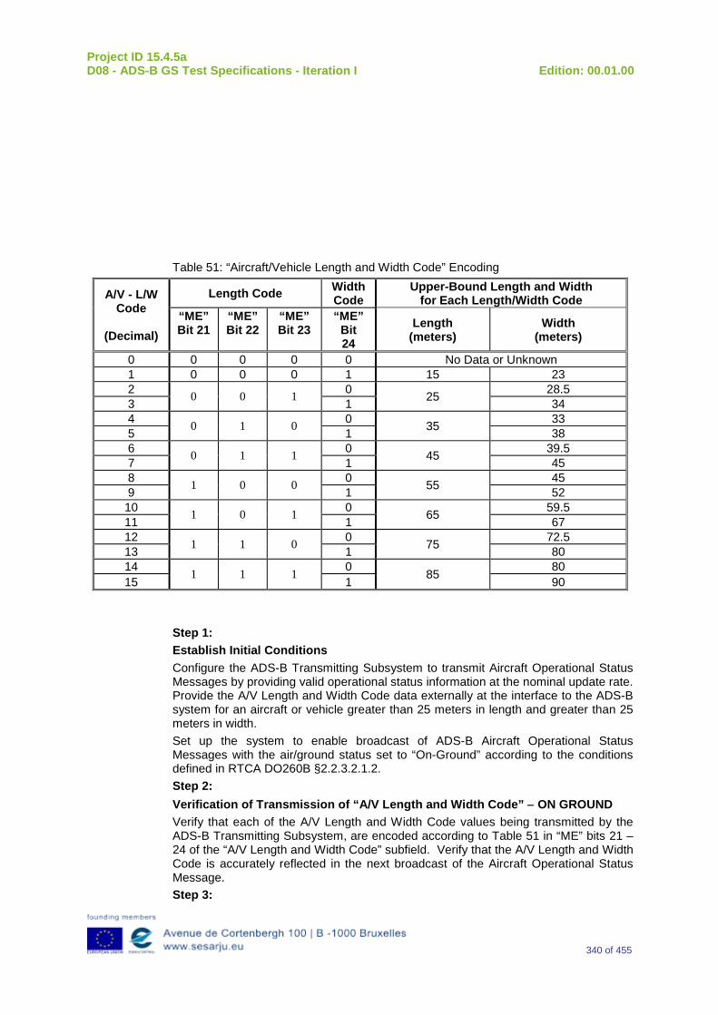
Project ID 15.4.5a D08 - ADS-B GS Test Specifications - Iteration I Edition: 00.01.00
340 of 455
Table 51: “Aircraft/Vehicle Length and Width Code” Encoding
A/V - L/W Code
(Decimal)
Length Code Width Code
Upper-Bound Length and Width for Each Length/Width Code
“ME” Bit 21
“ME” Bit 22
“ME” Bit 23
“ME” Bit 24
Length (meters)
Width (meters)
0 0 0 0 0 No Data or Unknown 1 0 0 0 1 15 23 2 0 0 1 0 25 28.5 3 1 34 4 0 1 0 0 35 33 5 1 38 6 0 1 1 0 45 39.5 7 1 45 8 1 0 0 0 55 45 9 1 52 10 1 0 1 0 65 59.5 11 1 67 12 1 1 0 0 75 72.5 13 1 80 14 1 1 1 0 85 80 15 1 90
Step 1: Establish Initial Conditions Configure the ADS-B Transmitting Subsystem to transmit Aircraft Operational Status Messages by providing valid operational status information at the nominal update rate. Provide the A/V Length and Width Code data externally at the interface to the ADS-B system for an aircraft or vehicle greater than 25 meters in length and greater than 25 meters in width. Set up the system to enable broadcast of ADS-B Aircraft Operational Status Messages with the air/ground status set to “On-Ground” according to the conditions defined in RTCA DO260B §2.2.3.2.1.2. Step 2: Verification of Transmission of “A/V Length and Width Code” − ON GROUND Verify that each of the A/V Length and Width Code values being transmitted by the ADS-B Transmitting Subsystem, are encoded according to Table 51 in “ME” bits 21 –24 of the “A/V Length and Width Code” subfield. Verify that the A/V Length and Width Code is accurately reflected in the next broadcast of the Aircraft Operational Status Message. Step 3:
Project ID 15.4.5a D08 - ADS-B GS Test Specifications - Iteration I Edition: 00.01.00
341 of 455
Verification of No Data Available Set up the ADS-B Transmitting Subsystem as in Step 1 above, and then remove the data input for the A/V Length and Width Codes. Verify that the value being transmitted for the A/V Length and Width Code is set to ALL ZERO (binary 0000) in the next broadcast of the Aircraft Operational Status Message. Step 4: Verification of Transmission of “A/V Length and Width Code” − AIRBORNE Set up the system to enable broadcast of ADS-B Messages with the the air/ground status set to “Airborne” according to the conditions defined in RTCA DO260B §2.2.3.2.1.2. Verify that the Aircraft Operational Status Message is being broadcast with Subtype=0, and that the A/V Length and Width Code is not reflected in the next broadcast of the Aircraft Operational Status Message.
Exercise Procedure:
Step Action Expected Reaction Pass/Fail Comment
1 Put the GS system under test into the related test configuration.
2 Prepare the test reporting capture tools to capture related GS system ASTERIX CAT-21 and, optional, GS system ‘Raw Data Output’ reports.
3 Prepare the test message source to play the test scenario.
4 Play the test scenario.
5 When the test scenario is complete, stop the recording of ASTERIX CAT-21 and, optional, GS system ‘Raw data output’ reports.
6 Analyze the recorded data:
7 Input test scenario versus ASTERIX CAT-21 reports and
8 Optional, Input test scenario versus GS system ‘Raw data output reports
9 Verify that the GS system
Project ID 15.4.5a D08 - ADS-B GS Test Specifications - Iteration I Edition: 00.01.00
342 of 455
under test has generated the expected outputs, and has fulfilled the test objective.
Exercise result:
Pass Fail Done By (Name, Organisation)
Configuration(s) during the exercise Date
Table 52: Verification Exercise Result
JJ.1.12 Verification SUT requirements N/A
JJ.1.13 Exercise Tool, Verification Technique and/or Platform
ADS-BGround Station
Power
ASTERIX(and Raw Data)
Recording
UTC Time Reference
RF Source(Message Generator)
The Exercise will be verified in a platform with the following foreseen tools/equipment:
-Ground Station ADS–B
-Message Generator
-ASTERIX (and Raw Data) Recording Tool
-Power Source
-UTC time Reference
The Item reported above will be capable to perform the functionalities reported below.
Ground Station ADS-B
The primary function of the 1090 GS is to receive 1090 MHz Mode S Extended Squitter messages, extract the data contained therein, and create appropriated ASTERIX Category 21 and 23 Reports (and optionally, Raw Data).
Message Generator
The Messages Generator will be capable to generate the data coming from the Remote System (ADS–B Ground Station or 1090 Receiver) like:
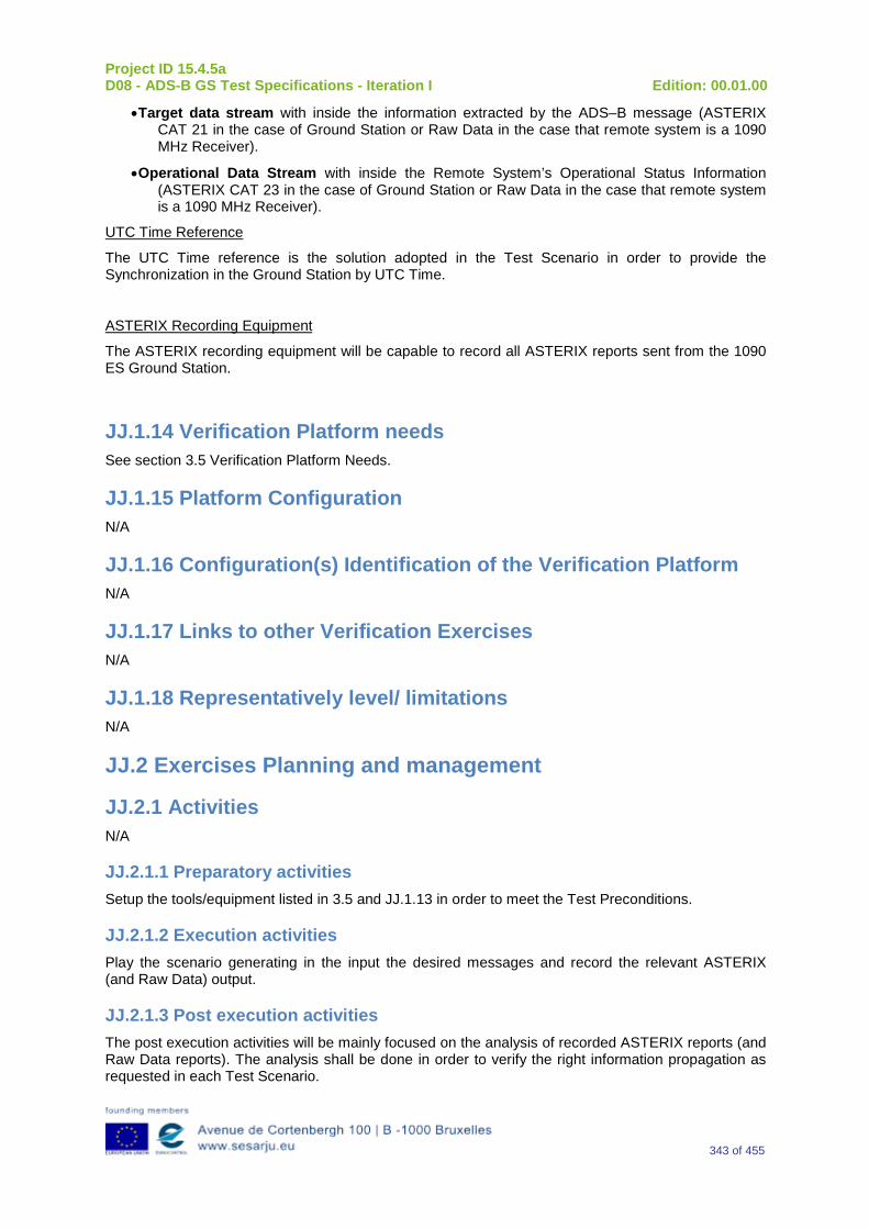
Project ID 15.4.5a D08 - ADS-B GS Test Specifications - Iteration I Edition: 00.01.00
343 of 455
•Target data stream with inside the information extracted by the ADS–B message (ASTERIX CAT 21 in the case of Ground Station or Raw Data in the case that remote system is a 1090 MHz Receiver).
•Operational Data Stream with inside the Remote System’s Operational Status Information (ASTERIX CAT 23 in the case of Ground Station or Raw Data in the case that remote system is a 1090 MHz Receiver).
UTC Time Reference
The UTC Time reference is the solution adopted in the Test Scenario in order to provide the Synchronization in the Ground Station by UTC Time.
ASTERIX Recording Equipment
The ASTERIX recording equipment will be capable to record all ASTERIX reports sent from the 1090 ES Ground Station.
JJ.1.14 Verification Platform needs See section 3.5 Verification Platform Needs.
JJ.1.15 Platform Configuration N/A
JJ.1.16 Configuration(s) Identification of the Verification Platform N/A
JJ.1.17 Links to other Verification Exercises N/A
JJ.1.18 Representatively level/ limitations N/A
JJ.2 Exercises Planning and management
JJ.2.1 Activities N/A
JJ.2.1.1 Preparatory activities Setup the tools/equipment listed in 3.5 and JJ.1.13 in order to meet the Test Preconditions.
JJ.2.1.2 Execution activities Play the scenario generating in the input the desired messages and record the relevant ASTERIX (and Raw Data) output.
JJ.2.1.3 Post execution activities The post execution activities will be mainly focused on the analysis of recorded ASTERIX reports (and Raw Data reports). The analysis shall be done in order to verify the right information propagation as requested in each Test Scenario.
Project ID 15.4.5a D08 - ADS-B GS Test Specifications - Iteration I Edition: 00.01.00
344 of 455
JJ.2.2 Human Resources N/A
JJ.2.3 Responsibilities in the exercise N/A
JJ.2.4 Training N/A
JJ.2.5 Time planning N/A
JJ.2.6 Risks N/A
JJ.2.7 Errors and Observation handling N/A
JJ.3 Analysis Specification
JJ.3.1 Data collection methods The data collection during the test will be Qualitative. In fact after test execution the analysis of ASTERIX Data will be performed verifying that the values reported in the output are in line with the values generated in the input.
JJ.3.2 Analysis method N/A
JJ.3.3 Data logging requirements The data logging requirements for this scenario will foresee at least ASTERIX CAT 21 items.
Project ID 15.4.5a D08 - ADS-B GS Test Specifications - Iteration I Edition: 00.01.00
345 of 455
Appendix KK Verification Exercise EXE-15.04.05.a-TS.0060.0130 GS: Navigation Integrity Code (NIC)
KK.1 Exercise Scope and Justification
KK.1.1 Exercise Level The level of the exercise is functional.
KK.1.2 Exercise Type The type of the exercise is Test.
KK.1.3 Description of the system being addressed ADS – B Ground Station.
KK.1.4 Context of the verification exercise This document is applied to FAT (Factory acceptance Test).
KK.1.5 Required Datasets 1090MHz Extended Squitter Messages input and 1090GS ASTERIX output.
KK.1.6 Verification objectives Verify the Requirements related to the enhancement 1090ES Technology, more specifically, the following requirements:
OBJ-15.04.05.a-TS.0060.0061 The aim of this objective is to check that the ADS–B Surveillance System is capable to decode the ADS-B message, in order to extract the available information, in accordance with the introduced changes in the DO-260B standard.
OBJ-15.04.05.a-TS.0060.0063 The aim of this objective is to check that the ADS-B System ground surveillance domain is able to transform the introduced DO-260B changes into Standard ASTERIX Category 21 data items.
KK.1.7 Inputs 1090MHz Extended Squitter Messages.
KK.1.8 Outputs Recordings of ASTERIX CAT-21 and, optionally, GS system ‘Raw data output’ reports.
Project ID 15.4.5a D08 - ADS-B GS Test Specifications - Iteration I Edition: 00.01.00
346 of 455
KK.1.9 Entrance criteria Start the generation of the input data.
KK.1.10 Exit Criteria Finished recording and performed analysis.
KK.1.11 Exercise procedure
Exercise ID/Title: EXE-15.4.5.a-TS.0060.0130 / Navigation Integrity Code (NIC)
Pass Criteria: This test is passed, when the recorded output has data items and corresponding values as expected.
Exercise Type: Test
Precondition(s): • Test equipment is setup as described above • GS under test is active, and ready for test.
Note(s): N/A
Device(s) in use: SUT is ADS-B GS.
These test procedures verify that the ADS-B Report Assembly Function extracts “TYPE” Code data (RTCA DO260B §2.2.3.2.3.1) and the NIC Supplement-B value (RTCA DO260B §2.2.3.2.3.3) from the ADS-B Airborne Position Message, or the “TYPE” Code data (RTCA DO260B §2.2.3.2.4.1) from the ADS-B Surface Position Message, and the NIC Supplement-A (RTCA DO260B §2.2.3.2.7.2.6) and NIC Supplement-C (RTCA DO260B §2.2.3.2.7.2.3.10) values from the ADS-B Aircraft Operational Status Message, and provides Navigation Integrity Category (NIC) information to the user application in the State Vector Report as specified in Table 53. Table 53: Navigation Integrity Category (NIC) Encoding.
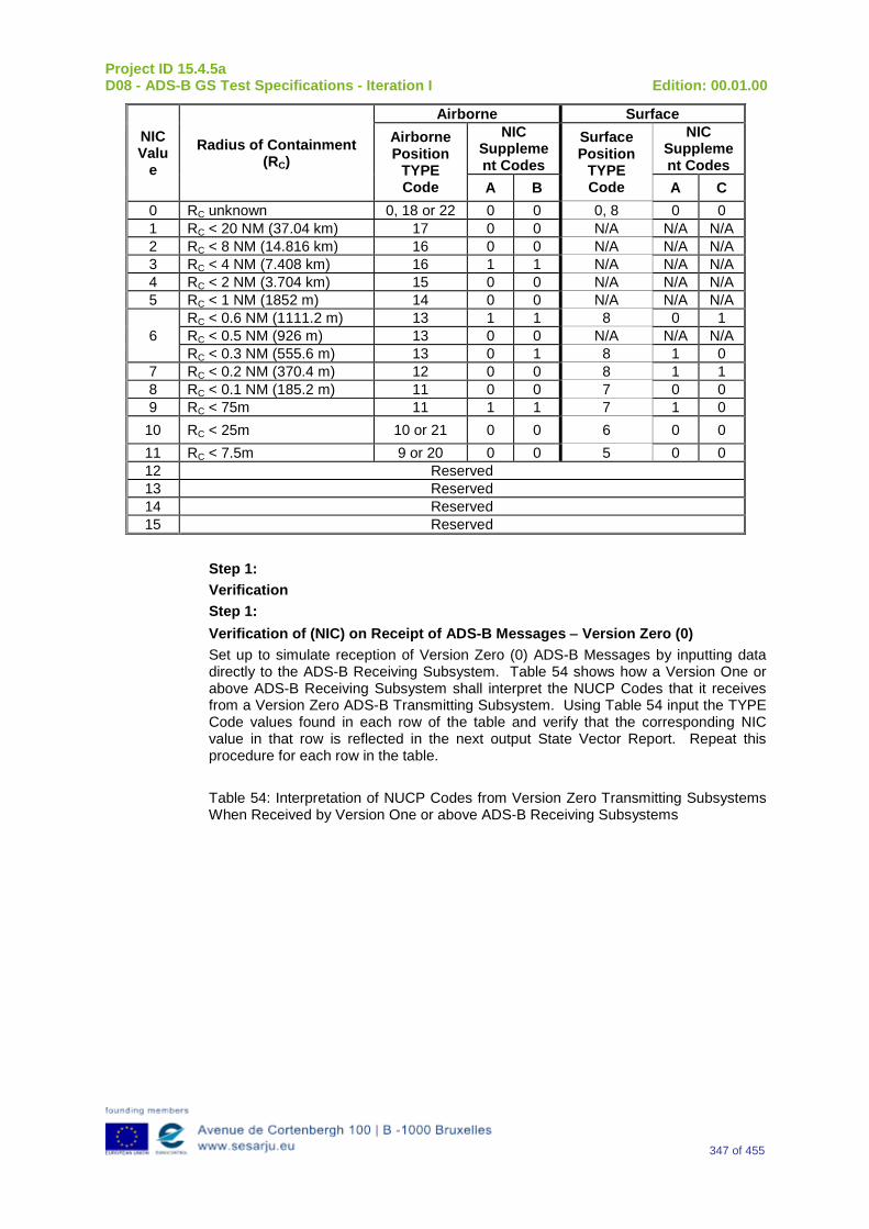
Project ID 15.4.5a D08 - ADS-B GS Test Specifications - Iteration I Edition: 00.01.00
347 of 455
NIC Valu
e Radius of Containment
(RC)
Airborne Surface Airborne Position
TYPE Code
NIC Supplement Codes
Surface Position
TYPE Code
NIC Supplement Codes
A B A C 0 RC unknown 0, 18 or 22 0 0 0, 8 0 0 1 RC < 20 NM (37.04 km) 17 0 0 N/A N/A N/A 2 RC < 8 NM (14.816 km) 16 0 0 N/A N/A N/A 3 RC < 4 NM (7.408 km) 16 1 1 N/A N/A N/A 4 RC < 2 NM (3.704 km) 15 0 0 N/A N/A N/A 5 RC < 1 NM (1852 m) 14 0 0 N/A N/A N/A
6 RC < 0.6 NM (1111.2 m) 13 1 1 8 0 1 RC < 0.5 NM (926 m) 13 0 0 N/A N/A N/A RC < 0.3 NM (555.6 m) 13 0 1 8 1 0
7 RC < 0.2 NM (370.4 m) 12 0 0 8 1 1 8 RC < 0.1 NM (185.2 m) 11 0 0 7 0 0 9 RC < 75m 11 1 1 7 1 0
10 RC < 25m 10 or 21 0 0 6 0 0 11 RC < 7.5m 9 or 20 0 0 5 0 0 12 Reserved 13 Reserved 14 Reserved 15 Reserved
Step 1: Verification Step 1: Verification of (NIC) on Receipt of ADS-B Messages − Version Zero (0) Set up to simulate reception of Version Zero (0) ADS-B Messages by inputting data directly to the ADS-B Receiving Subsystem. Table 54 shows how a Version One or above ADS-B Receiving Subsystem shall interpret the NUCP Codes that it receives from a Version Zero ADS-B Transmitting Subsystem. Using Table 54 input the TYPE Code values found in each row of the table and verify that the corresponding NIC value in that row is reflected in the next output State Vector Report. Repeat this procedure for each row in the table. Table 54: Interpretation of NUCP Codes from Version Zero Transmitting Subsystems When Received by Version One or above ADS-B Receiving Subsystems
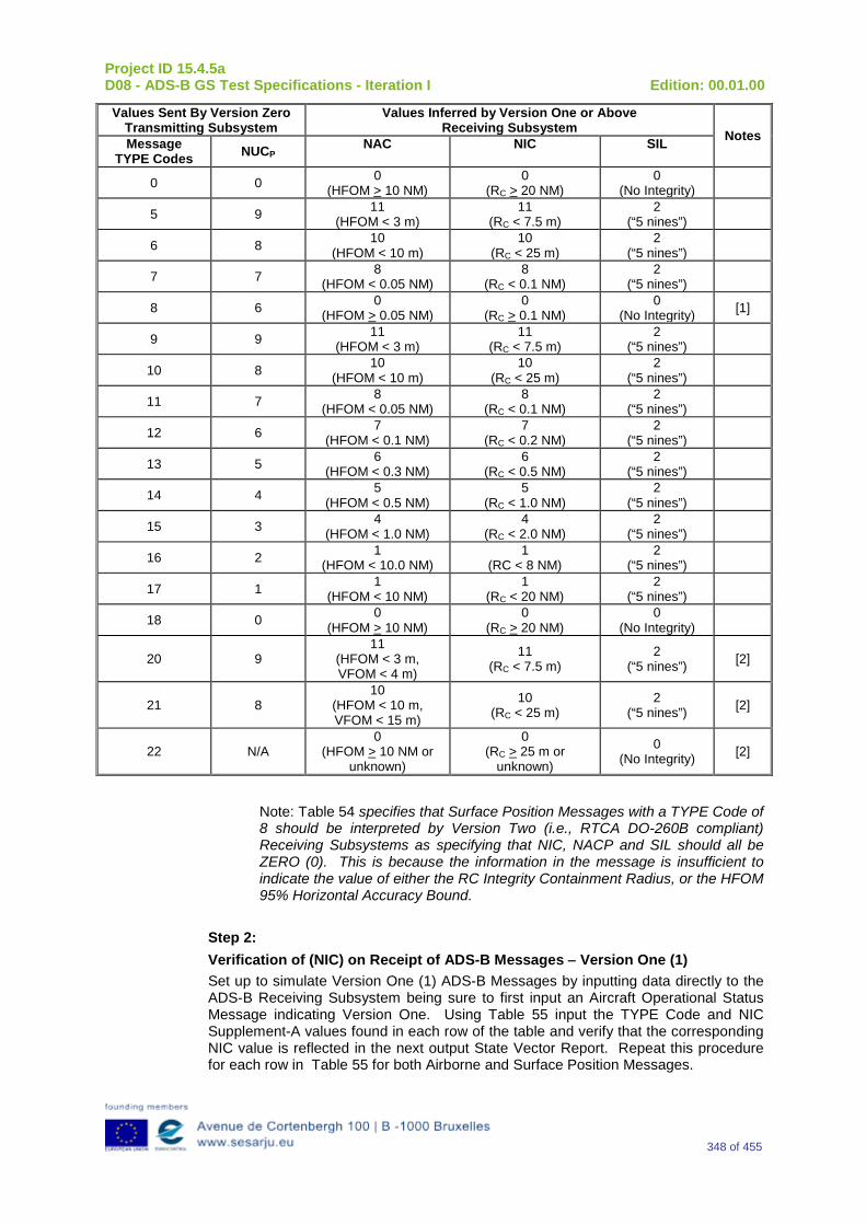
Project ID 15.4.5a D08 - ADS-B GS Test Specifications - Iteration I Edition: 00.01.00
348 of 455
Values Sent By Version Zero Transmitting Subsystem
Values Inferred by Version One or Above Receiving Subsystem Notes Message
TYPE Codes NUCP NAC
NIC
SIL
0 0 0 (HFOM > 10 NM)
0 (RC > 20 NM)
0 (No Integrity)
5 9 11 (HFOM < 3 m)
11 (RC < 7.5 m)
2 (“5 nines”)
6 8 10 (HFOM < 10 m)
10 (RC < 25 m)
2 (“5 nines”)
7 7 8 (HFOM < 0.05 NM)
8 (RC < 0.1 NM)
2 (“5 nines”)
8 6 0 (HFOM > 0.05 NM)
0 (RC > 0.1 NM)
0 (No Integrity) [1]
9 9 11 (HFOM < 3 m)
11 (RC < 7.5 m)
2 (“5 nines”)
10 8 10 (HFOM < 10 m)
10 (RC < 25 m)
2 (“5 nines”)
11 7 8 (HFOM < 0.05 NM)
8 (RC < 0.1 NM)
2 (“5 nines”)
12 6 7 (HFOM < 0.1 NM)
7 (RC < 0.2 NM)
2 (“5 nines”)
13 5 6 (HFOM < 0.3 NM)
6 (RC < 0.5 NM)
2 (“5 nines”)
14 4 5 (HFOM < 0.5 NM)
5 (RC < 1.0 NM)
2 (“5 nines”)
15 3 4 (HFOM < 1.0 NM)
4 (RC < 2.0 NM)
2 (“5 nines”)
16 2 1 (HFOM < 10.0 NM)
1 (RC < 8 NM)
2 (“5 nines”)
17 1 1 (HFOM < 10 NM)
1 (RC < 20 NM)
2 (“5 nines”)
18 0 0 (HFOM > 10 NM)
0 (RC > 20 NM)
0 (No Integrity)
20 9 11
(HFOM < 3 m, VFOM < 4 m)
11 (RC < 7.5 m)
2 (“5 nines”) [2]
21 8 10
(HFOM < 10 m, VFOM < 15 m)
10 (RC < 25 m)
2 (“5 nines”) [2]
22 N/A 0
(HFOM > 10 NM or unknown)
0 (RC > 25 m or
unknown)
0 (No Integrity) [2]
Note: Table 54 specifies that Surface Position Messages with a TYPE Code of 8 should be interpreted by Version Two (i.e., RTCA DO-260B compliant) Receiving Subsystems as specifying that NIC, NACP and SIL should all be ZERO (0). This is because the information in the message is insufficient to indicate the value of either the RC Integrity Containment Radius, or the HFOM 95% Horizontal Accuracy Bound.
Step 2: Verification of (NIC) on Receipt of ADS-B Messages − Version One (1) Set up to simulate Version One (1) ADS-B Messages by inputting data directly to the ADS-B Receiving Subsystem being sure to first input an Aircraft Operational Status Message indicating Version One. Using Table 55 input the TYPE Code and NIC Supplement-A values found in each row of the table and verify that the corresponding NIC value is reflected in the next output State Vector Report. Repeat this procedure for each row in Table 55 for both Airborne and Surface Position Messages.
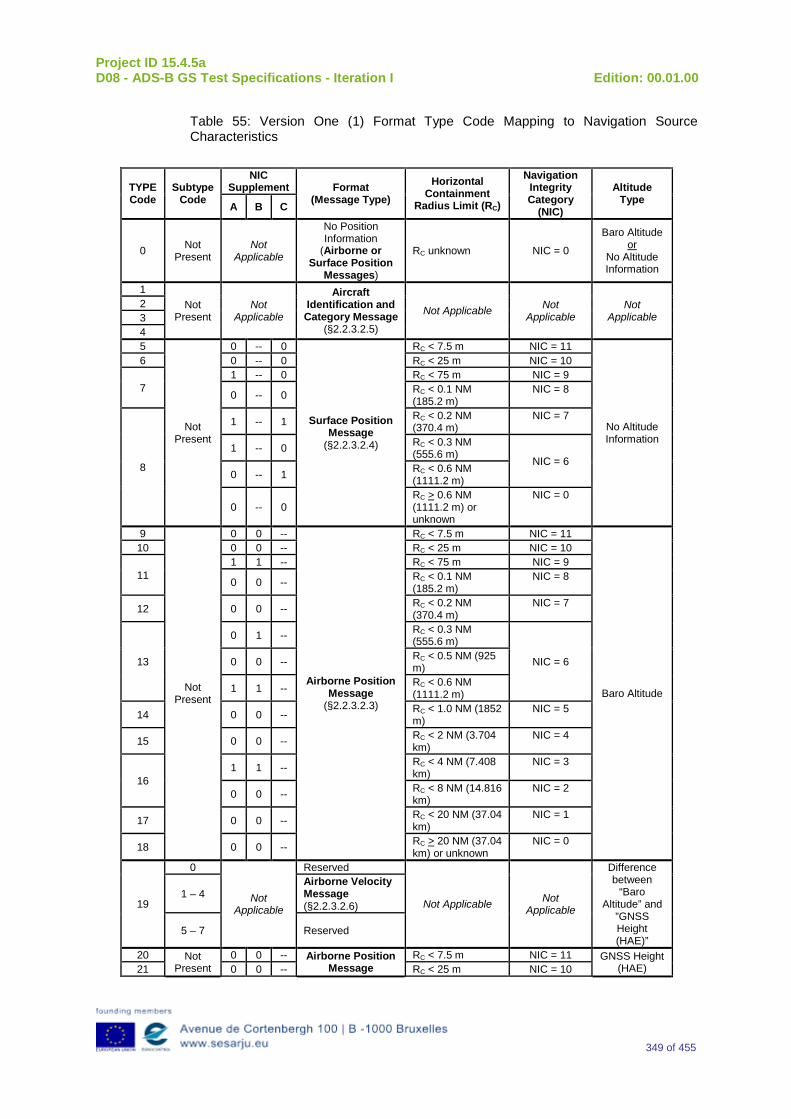
Project ID 15.4.5a D08 - ADS-B GS Test Specifications - Iteration I Edition: 00.01.00
349 of 455
Table 55: Version One (1) Format Type Code Mapping to Navigation Source Characteristics
TYPE Code
Subtype Code
NIC Supplement Format
(Message Type) Horizontal
Containment Radius Limit (RC)
Navigation Integrity Category
(NIC)
Altitude Type A B C
0 Not Present
Not Applicable
No Position Information
(Airborne or Surface Position
Messages)
RC unknown NIC = 0
Baro Altitude or
No Altitude Information
1 Not
Present Not
Applicable
Aircraft Identification and Category Message
(§2.2.3.2.5)
Not Applicable Not Applicable
Not Applicable
2 3 4 5
Not Present
0 -- 0
Surface Position Message
(§2.2.3.2.4)
RC < 7.5 m NIC = 11
No Altitude Information
6 0 -- 0 RC < 25 m NIC = 10
7 1 -- 0 RC < 75 m NIC = 9
0 -- 0 RC < 0.1 NM (185.2 m)
NIC = 8
8
1 -- 1 RC < 0.2 NM (370.4 m)
NIC = 7
1 -- 0 RC < 0.3 NM (555.6 m)
NIC = 6 0 -- 1 RC < 0.6 NM
(1111.2 m)
0 -- 0 RC > 0.6 NM (1111.2 m) or unknown
NIC = 0
9
Not Present
0 0 --
Airborne Position Message
(§2.2.3.2.3)
RC < 7.5 m NIC = 11
Baro Altitude
10 0 0 -- RC < 25 m NIC = 10
11 1 1 -- RC < 75 m NIC = 9
0 0 -- RC < 0.1 NM (185.2 m)
NIC = 8
12 0 0 -- RC < 0.2 NM (370.4 m)
NIC = 7
13
0 1 -- RC < 0.3 NM (555.6 m)
NIC = 6 0 0 -- RC < 0.5 NM (925 m)
1 1 -- RC < 0.6 NM (1111.2 m)
14 0 0 -- RC < 1.0 NM (1852 m)
NIC = 5
15 0 0 -- RC < 2 NM (3.704 km)
NIC = 4
16 1 1 -- RC < 4 NM (7.408
km) NIC = 3
0 0 -- RC < 8 NM (14.816 km)
NIC = 2
17 0 0 -- RC < 20 NM (37.04 km)
NIC = 1
18 0 0 -- RC > 20 NM (37.04 km) or unknown
NIC = 0
19
0
Not Applicable
Reserved
Not Applicable Not Applicable
Difference between
“Baro Altitude” and
”GNSS Height (HAE)”
1 – 4 Airborne Velocity Message (§2.2.3.2.6)
5 – 7 Reserved
20 Not Present
0 0 -- Airborne Position Message
RC < 7.5 m NIC = 11 GNSS Height (HAE) 21 0 0 -- RC < 25 m NIC = 10
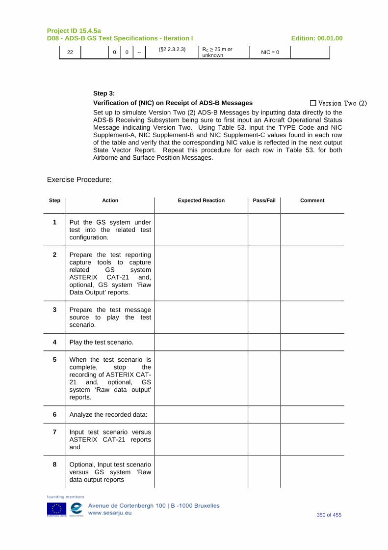
Project ID 15.4.5a D08 - ADS-B GS Test Specifications - Iteration I Edition: 00.01.00
350 of 455
22 0 0 -- (§2.2.3.2.3) RC > 25 m or unknown NIC = 0
Step 3: Verification of (NIC) on Receipt of ADS-B Messages Ve rs io n Two (2) Set up to simulate Version Two (2) ADS-B Messages by inputting data directly to the ADS-B Receiving Subsystem being sure to first input an Aircraft Operational Status Message indicating Version Two. Using Table 53. input the TYPE Code and NIC Supplement-A, NIC Supplement-B and NIC Supplement-C values found in each row of the table and verify that the corresponding NIC value is reflected in the next output State Vector Report. Repeat this procedure for each row in Table 53. for both Airborne and Surface Position Messages.
Exercise Procedure:
Step Action Expected Reaction Pass/Fail Comment
1 Put the GS system under test into the related test configuration.
2 Prepare the test reporting capture tools to capture related GS system ASTERIX CAT-21 and, optional, GS system ‘Raw Data Output’ reports.
3 Prepare the test message source to play the test scenario.
4 Play the test scenario.
5 When the test scenario is complete, stop the recording of ASTERIX CAT-21 and, optional, GS system ‘Raw data output’ reports.
6 Analyze the recorded data:
7 Input test scenario versus ASTERIX CAT-21 reports and
8 Optional, Input test scenario versus GS system ‘Raw data output reports
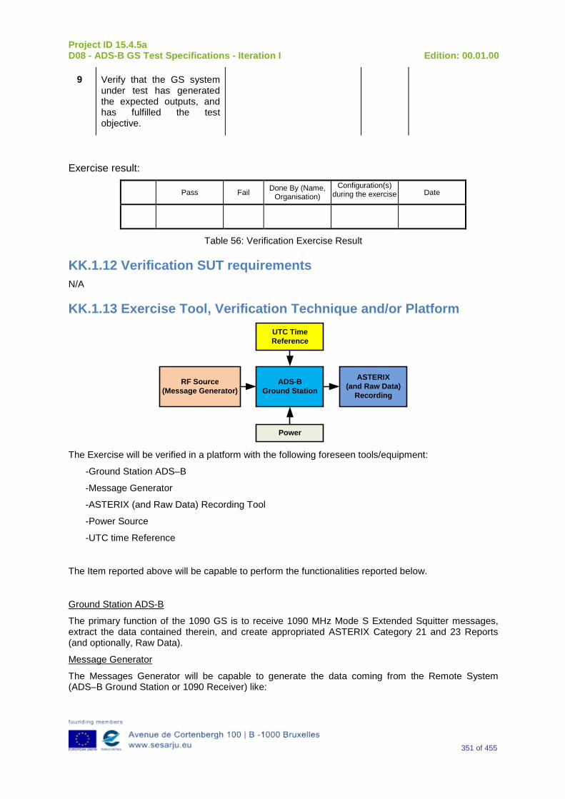
Project ID 15.4.5a D08 - ADS-B GS Test Specifications - Iteration I Edition: 00.01.00
351 of 455
9 Verify that the GS system under test has generated the expected outputs, and has fulfilled the test objective.
Exercise result:
Pass Fail Done By (Name, Organisation)
Configuration(s) during the exercise Date
Table 56: Verification Exercise Result
KK.1.12 Verification SUT requirements N/A
KK.1.13 Exercise Tool, Verification Technique and/or Platform
ADS-BGround Station
Power
ASTERIX(and Raw Data)
Recording
UTC Time Reference
RF Source(Message Generator)
The Exercise will be verified in a platform with the following foreseen tools/equipment:
-Ground Station ADS–B
-Message Generator
-ASTERIX (and Raw Data) Recording Tool
-Power Source
-UTC time Reference
The Item reported above will be capable to perform the functionalities reported below.
Ground Station ADS-B
The primary function of the 1090 GS is to receive 1090 MHz Mode S Extended Squitter messages, extract the data contained therein, and create appropriated ASTERIX Category 21 and 23 Reports (and optionally, Raw Data).
Message Generator
The Messages Generator will be capable to generate the data coming from the Remote System (ADS–B Ground Station or 1090 Receiver) like:

Project ID 15.4.5a D08 - ADS-B GS Test Specifications - Iteration I Edition: 00.01.00
352 of 455
•Target data stream with inside the information extracted by the ADS–B message (ASTERIX CAT 21 in the case of Ground Station or Raw Data in the case that remote system is a 1090 MHz Receiver).
•Operational Data Stream with inside the Remote System’s Operational Status Information (ASTERIX CAT 23 in the case of Ground Station or Raw Data in the case that remote system is a 1090 MHz Receiver).
UTC Time Reference
The UTC Time reference is the solution adopted in the Test Scenario in order to provide the Synchronization in the Ground Station by UTC Time.
ASTERIX Recording Equipment
The ASTERIX recording equipment will be capable to record all ASTERIX reports sent from the 1090 ES Ground Station.
KK.1.14 Verification Platform needs See section 3.5 Verification Platform Needs.
KK.1.15 Platform Configuration N/A
KK.1.16 Configuration(s) Identification of the Verification Platform N/A
KK.1.17 Links to other Verification Exercises N/A
KK.1.18 Representatively level/ limitations N/A
KK.2 Exercises Planning and management
KK.2.1 Activities N/A
KK.2.1.1 Preparatory activities Setup the tools/equipment listed in 3.5 and KK.1.13 in order to meet the Test Preconditions.
KK.2.1.2 Execution activities Play the scenario generating in the input the desired messages and record the relevant ASTERIX (and Raw Data) output.
KK.2.1.3 Post execution activities The post execution activities will be mainly focused on the analysis of recorded ASTERIX reports (and Raw Data reports). The analysis shall be done in order to verify the right information propagation as requested in each Test Scenario.
Project ID 15.4.5a D08 - ADS-B GS Test Specifications - Iteration I Edition: 00.01.00
353 of 455
KK.2.2 Human Resources N/A
KK.2.3 Responsibilities in the exercise N/A
KK.2.4 Training N/A
KK.2.5 Time planning N/A
KK.2.6 Risks N/A
KK.2.7 Errors and Observation handling N/A
KK.3 Analysis Specification
KK.3.1 Data collection methods The data collection during the test will be Qualitative. In fact after test execution the analysis of ASTERIX Data will be performed verifying that the values reported in the output are in line with the values generated in input.
KK.3.2 Analysis method N/A
KK.3.3 Data logging requirements The data logging requirements for this scenario will foresee at least ASTERIX CAT 21 items.
Project ID 15.4.5a D08 - ADS-B GS Test Specifications - Iteration I Edition: 00.01.00
354 of 455
Appendix LL Verification Exercise EXE-15.04.05.a-TS.0060.0140 GS: “NACP” Subfield in Target State and Status Messages
LL.1 Exercise Scope and Justification
LL.1.1 Exercise Level The level of the exercise is functional.
LL.1.2 Exercise Type The type of the exercise is Test.
LL.1.3 Description of the system being addressed ADS – B Ground Station.
LL.1.4 Context of the verification exercise This document is applied to FAT (Factory acceptance Test).
LL.1.5 Required Datasets 1090MHz Extended Squitter Messages input and 1090GS ASTERIX output.
LL.1.6 Verification objectives Verify the Requirements related to the enhancement 1090ES Technology, more specifically, the following requirements:
OBJ-15.04.05.a-TS.0060.0061 The aim of this objective is to check that the ADS–B Surveillance System is capable to decode the ADS-B message, in order to extract the available information, in accordance with the introduced changes in the DO-260B standard.
OBJ-15.04.05.a-TS.0060.0063 The aim of this objective is to check that the ADS-B System ground surveillance domain is able to transform the introduced DO-260B changes into Standard ASTERIX Category 21 data items.
LL.1.7 Inputs 1090MHz Extended Squitter Messages.
LL.1.8 Outputs Recordings of ASTERIX CAT-21 and, optionally, GS system ‘Raw data output’ reports.
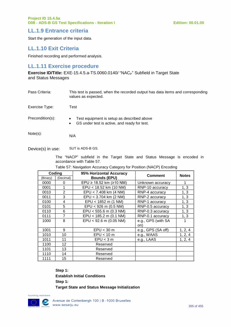
Project ID 15.4.5a D08 - ADS-B GS Test Specifications - Iteration I Edition: 00.01.00
355 of 455
LL.1.9 Entrance criteria Start the generation of the input data.
LL.1.10 Exit Criteria Finished recording and performed analysis.
LL.1.11 Exercise procedure Exercise ID/Title: EXE-15.4.5.a-TS.0060.0140/ “NACP” Subfield in Target State and Status Messages
Pass Criteria: This test is passed, when the recorded output has data items and corresponding
values as expected.
Exercise Type: Test
Precondition(s): • Test equipment is setup as described above • GS under test is active, and ready for test.
Note(s): N/A
Device(s) in use: SUT is ADS-B GS.
The “NACP” subfield in the Target State and Status Message is encoded in accordance with Table 57. Table 57: Navigation Accuracy Category for Position (NACP) Encoding
Coding 95% Horizontal Accuracy Bounds (EPU) Comment Notes
(Binary) (Decimal) 0000 0 EPU ≥ 18.52 km (≥10 NM) Unknown accuracy 1 0001 1 EPU < 18.52 km (10 NM) RNP-10 accuracy 1, 3 0010 2 EPU < 7.408 km (4 NM) RNP-4 accuracy 1, 3 0011 3 EPU < 3.704 km (2 NM) RNP-2 accuracy 1, 3 0100 4 EPU < 1852 m (1 NM) RNP-1 accuracy 1, 3 0101 5 EPU < 926 m (0.5 NM) RNP-0.5 accuracy 1, 3 0110 6 EPU < 555.6 m (0.3 NM) RNP-0.3 accuracy 1, 3 0111 7 EPU < 185.2 m (0.1 NM) RNP-0.1 accuracy 1, 3 1000 8 EPU < 92.6 m (0.05 NM) e.g., GPS (with SA
on) 1
1001 9 EPU < 30 m e.g., GPS (SA off) 1, 2, 4 1010 10 EPU < 10 m e.g., WAAS 1, 2, 4 1011 11 EPU < 3 m e.g., LAAS 1, 2, 4 1100 12 Reserved 1101 13 Reserved 1110 14 Reserved 1111 15 Reserved
Step 1: Establish Initial Conditions Step 1: Target State and Status Message Initialization
Project ID 15.4.5a D08 - ADS-B GS Test Specifications - Iteration I Edition: 00.01.00
356 of 455
Via the appropriate interface, provide the ADS-B Transmitting Subsystem with valid Mode Control Panel Selected Altitude data in order to initialize transmission of Target State and Status Messages. Step 2: Verification of NACP Transmission Via the appropriate interface, provide the ADS-B Transmitting Subsystem with each of the EPU values indicated in Table 57. Verify that for each input NACP parameter that is specified by the EPU value in Table 2-71, that the system generates ADS-B Messages with the NACP subfield set equal to the corresponding binary coding value shown in Table 57. Step 3: Verification of NACP − Data Lifetime Rerun the Test Procedure in Step 1. Remove the data source input for valid trajectory information for a period of at least 2 seconds. Verify that “ME” bits 40 – 43 in the Target State and Status Message are set to a value of ZERO (binary 0000).
Exercise Procedure:
Step Action Expected Reaction Pass/Fail Comment
1 Put the GS system under test into the related test configuration.
2 Prepare the test reporting capture tools to capture related GS system ASTERIX CAT-21 and, optional, GS system ‘Raw Data Output’ reports.
3 Prepare the test message source to play the test scenario.
4 Play the test scenario.
5 When the test scenario is complete, stop the recording of ASTERIX CAT-21 and, optional, GS system ‘Raw data output’ reports.
6 Analyze the recorded data:
7 Input test scenario versus ASTERIX CAT-21 reports and
8 Optional, Input test scenario versus GS system ‘Raw
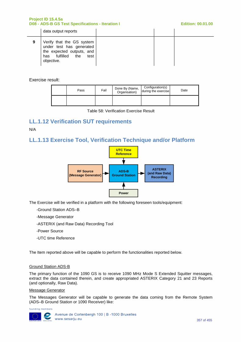
Project ID 15.4.5a D08 - ADS-B GS Test Specifications - Iteration I Edition: 00.01.00
357 of 455
data output reports
9 Verify that the GS system under test has generated the expected outputs, and has fulfilled the test objective.
Exercise result:
Pass Fail Done By (Name, Organisation)
Configuration(s) during the exercise Date
Table 58: Verification Exercise Result
LL.1.12 Verification SUT requirements N/A
LL.1.13 Exercise Tool, Verification Technique and/or Platform
ADS-BGround Station
Power
ASTERIX(and Raw Data)
Recording
UTC Time Reference
RF Source(Message Generator)
The Exercise will be verified in a platform with the following foreseen tools/equipment:
-Ground Station ADS–B
-Message Generator
-ASTERIX (and Raw Data) Recording Tool
-Power Source
-UTC time Reference
The Item reported above will be capable to perform the functionalities reported below.
Ground Station ADS-B
The primary function of the 1090 GS is to receive 1090 MHz Mode S Extended Squitter messages, extract the data contained therein, and create appropriated ASTERIX Category 21 and 23 Reports (and optionally, Raw Data).
Message Generator
The Messages Generator will be capable to generate the data coming from the Remote System (ADS–B Ground Station or 1090 Receiver) like:
Project ID 15.4.5a D08 - ADS-B GS Test Specifications - Iteration I Edition: 00.01.00
358 of 455
•Target data stream with inside the information extracted by the ADS–B message (ASTERIX CAT 21 in the case of Ground Station or Raw Data in the case that remote system is a 1090 MHz Receiver).
•Operational Data Stream with inside the Remote System’s Operational Status Information (ASTERIX CAT 23 in the case of Ground Station or Raw Data in the case that remote system is a 1090 MHz Receiver).
UTC Time Reference
The UTC Time reference is the solution adopted in the Test Scenario in order to provide the Synchronization in the Ground Station by UTC Time.
ASTERIX Recording Equipment
The ASTERIX recording equipment will be capable to record all ASTERIX reports sent from the 1090 ES Ground Station.
LL.1.14 Verification Platform needs See section 3.5 Verification Platform Needs.
LL.1.15 Platform Configuration N/A
LL.1.16 Configuration(s) Identification of the Verification Platform N/A
LL.1.17 Links to other Verification Exercises N/A
LL.1.18 Representatively level/ limitations N/A
LL.2 Exercises Planning and management
LL.2.1 Activities N/A
LL.2.1.1 Preparatory activities Setup the tools/equipment listed in 3.5 and LL.1.13 in order to meet the Test Preconditions.
LL.2.1.2 Execution activities Play the scenario generating in the input the desired messages and record the relevant ASTERIX (and Raw Data) output.
LL.2.1.3 Post execution activities The post execution activities will be mainly focused on the analysis of recorded ASTERIX reports (and Raw Data reports). The analysis shall be done in order to verify the right information propagation as requested in each Test Scenario.
Project ID 15.4.5a D08 - ADS-B GS Test Specifications - Iteration I Edition: 00.01.00
359 of 455
LL.2.2 Human Resources N/A
LL.2.3 Responsibilities in the exercise N/A
LL.2.4 Training N/A
LL.2.5 Time planning N/A
LL.2.6 Risks N/A
LL.2.7 Errors and Observation handling N/A
LL.3 Analysis Specification
LL.3.1 Data collection methods The data collection during the test will be Qualitative. In fact after test execution the analysis of ASTERIX Data will be performed verifying that the values reported in the output are in line with the values generated in the input.
LL.3.2 Analysis method N/A
LL.3.3 Data logging requirements The data logging requirements for this scenario will foresee at least ASTERIX CAT 21 items.
Project ID 15.4.5a D08 - ADS-B GS Test Specifications - Iteration I Edition: 00.01.00
360 of 455
Appendix MM Verification Exercise EXE-15.04.05.a-TS.0060.0150 GS: “NACV” Subfield in Airborne Velocity Messages - Subtype=1
MM.1 Exercise Scope and Justification
MM.1.1 Exercise Level The level of the exercise is functional.
MM.1.2 Exercise Type The type of the exercise is Test.
MM.1.3 Description of the system being addressed ADS – B Ground Station.
MM.1.4 Context of the verification exercise This document is applied to FAT (Factory acceptance Test).
MM.1.5 Required Datasets 1090MHz Extended Squitter Messages input and 1090GS ASTERIX output.
MM.1.6 Verification objectives Verify the Requirements related to the enhancement 1090ES Technology, more specifically, the following requirements:
OBJ-15.04.05.a-TS.0060.0061 The aim of this objective is to check that the ADS–B Surveillance System is capable to decode the ADS-B message, in order to extract the available information, in accordance with the introduced changes in the DO-260B standard.
OBJ-15.04.05.a-TS.0060.0063 The aim of this objective is to check that the ADS-B System ground surveillance domain is able to transform the introduced DO-260B changes into Standard ASTERIX Category 21 data items.
MM.1.7 Inputs 1090MHz Extended Squitter Messages.
MM.1.8 Outputs Recordings of ASTERIX CAT-21 and, optionally, GS system ‘Raw data output’ reports.
Project ID 15.4.5a D08 - ADS-B GS Test Specifications - Iteration I Edition: 00.01.00
361 of 455
MM.1.9 Entrance criteria Start the generation of the input data.
MM.1.10 Exit Criteria Finished recording and performed analysis.
MM.1.11 Exercise procedure
Exercise ID/Title: EXE-15.4.5.a-TS.0060.0150/ “NACV” Subfield in Airborne Velocity Messages - Subtype=1
Pass Criteria: This test is passed, when the recorded output has data items and corresponding values as expected.
Exercise Type: Test
Precondition(s): • Test equipment is setup as described above • GS under test is active, and ready for test.
Note(s): N/A
Device(s) in use: SUT is ADS-B GS.
The “NACV” subfield is used to indicate the Navigation Accuracy Category for Velocity as specified in Table 59 These test procedures are intended for use for Airborne Velocity Messages of all Subtypes. The type and values of the input Velocity data should be set so as to generate Airborne Velocity Messages for all appropriate Subtype fields.
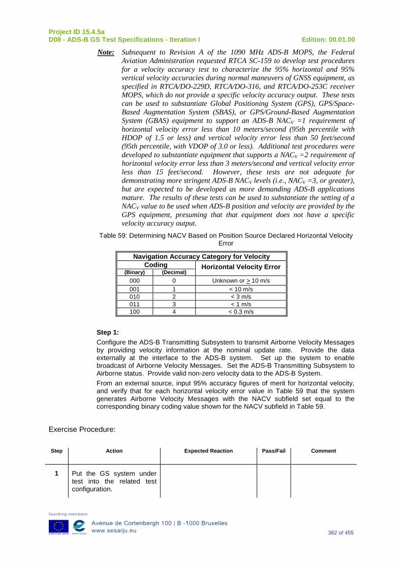
Project ID 15.4.5a D08 - ADS-B GS Test Specifications - Iteration I Edition: 00.01.00
362 of 455
Note: Subsequent to Revision A of the 1090 MHz ADS-B MOPS, the Federal Aviation Administration requested RTCA SC-159 to develop test procedures for a velocity accuracy test to characterize the 95% horizontal and 95% vertical velocity accuracies during normal maneuvers of GNSS equipment, as specified in RTCA/DO-229D, RTCA/DO-316, and RTCA/DO-253C receiver MOPS, which do not provide a specific velocity accuracy output. These tests can be used to substantiate Global Positioning System (GPS), GPS/Space-Based Augmentation System (SBAS), or GPS/Ground-Based Augmentation System (GBAS) equipment to support an ADS-B NACV =1 requirement of horizontal velocity error less than 10 meters/second (95th percentile with HDOP of 1.5 or less) and vertical velocity error less than 50 feet/second (95th percentile, with VDOP of 3.0 or less). Additional test procedures were developed to substantiate equipment that supports a NACV =2 requirement of horizontal velocity error less than 3 meters/second and vertical velocity error less than 15 feet/second. However, these tests are not adequate for demonstrating more stringent ADS-B NACV levels (i.e., NACV =3, or greater), but are expected to be developed as more demanding ADS-B applications mature. The results of these tests can be used to substantiate the setting of a NACV value to be used when ADS-B position and velocity are provided by the GPS equipment, presuming that that equipment does not have a specific velocity accuracy output.
Table 59: Determining NACV Based on Position Source Declared Horizontal Velocity Error
Navigation Accuracy Category for Velocity Coding Horizontal Velocity Error
(Binary) (Decimal) 000 0 Unknown or > 10 m/s 001 1 < 10 m/s 010 2 < 3 m/s 011 3 < 1 m/s 100 4 < 0.3 m/s
Step 1: Configure the ADS-B Transmitting Subsystem to transmit Airborne Velocity Messages by providing velocity information at the nominal update rate. Provide the data externally at the interface to the ADS-B system. Set up the system to enable broadcast of Airborne Velocity Messages. Set the ADS-B Transmitting Subsystem to Airborne status. Provide valid non-zero velocity data to the ADS-B System. From an external source, input 95% accuracy figures of merit for horizontal velocity, and verify that for each horizontal velocity error value in Table 59 that the system generates Airborne Velocity Messages with the NACV subfield set equal to the corresponding binary coding value shown for the NACV subfield in Table 59.
Exercise Procedure:
Step Action Expected Reaction Pass/Fail Comment
1 Put the GS system under test into the related test configuration.
Project ID 15.4.5a D08 - ADS-B GS Test Specifications - Iteration I Edition: 00.01.00
363 of 455
2 Prepare the test reporting capture tools to capture related GS system ASTERIX CAT-21 and, optional, GS system ‘Raw Data Output’ reports.
3 Prepare the test message source to play the test scenario.
4 Play the test scenario.
5 When the test scenario is complete, stop the recording of ASTERIX CAT-21 and, optional, GS system ‘Raw data output’ reports.
6 Analyze the recorded data:
7 Input test scenario versus ASTERIX CAT-21 reports and
8 Optional, Input test scenario versus GS system ‘Raw data output reports
9 Verify that the GS system under test has generated the expected outputs, and has fulfilled the test objective.
Exercise result:
Pass Fail Done By (Name, Organisation)
Configuration(s) during the exercise Date
Table 60: Verification Exercise Result
MM.1.12 Verification SUT requirements N/A

Project ID 15.4.5a D08 - ADS-B GS Test Specifications - Iteration I Edition: 00.01.00
364 of 455
MM.1.13 Exercise Tool, Verification Technique and/or Platform
ADS-BGround Station
Power
ASTERIX(and Raw Data)
Recording
UTC Time Reference
RF Source(Message Generator)
The Exercise will be verified in a platform with the following foreseen tools/equipment:
-Ground Station ADS–B
-Message Generator
-ASTERIX (and Raw Data) Recording Tool
-Power Source
-UTC time Reference
The Item reported above will be capable to perform the functionalities reported below.
Ground Station ADS-B
The primary function of the 1090 GS is to receive 1090 MHz Mode S Extended Squitter messages, extract the data contained therein, and create appropriated ASTERIX Category 21 and 23 Reports (and optionally, Raw Data).
Message Generator
The Messages Generator will be capable to generate the data coming from the Remote System (ADS–B Ground Station or 1090 Receiver) like:
•Target data stream with inside the information extracted by the ADS–B message (ASTERIX CAT 21 in the case of Ground Station or Raw Data in the case that remote system is a 1090 MHz Receiver).
•Operational Data Stream with inside the Remote System’s Operational Status Information (ASTERIX CAT 23 in the case of Ground Station or Raw Data in the case that remote system is a 1090 MHz Receiver).
UTC Time Reference
The UTC Time reference is the solution adopted in the Test Scenario in order to provide the Synchronization in the Ground Station by UTC Time.
ASTERIX Recording Equipment
The ASTERIX recording equipment will be capable to record all ASTERIX reports sent from the 1090 ES Ground Station.
MM.1.14 Verification Platform needs See section 3.5 Verification Platform Needs.
Project ID 15.4.5a D08 - ADS-B GS Test Specifications - Iteration I Edition: 00.01.00
365 of 455
MM.1.15 Platform Configuration N/A
MM.1.16 Configuration(s) Identification of the Verification Platform N/A
MM.1.17 Links to other Verification Exercises N/A
MM.1.18 Representatively level/ limitations N/A
MM.2 Exercises Planning and management
MM.2.1 Activities N/A
MM.2.1.1 Preparatory activities Setup the tools/equipment listed in 3.5 and MM.1.13 in order to meet the Test Preconditions.
MM.2.1.2 Execution activities Play the scenario generating in the input the desired messages and record the relevant ASTERIX (and Raw Data) output.
MM.2.1.3 Post execution activities The post execution activities will be mainly focused on the analysis of recorded ASTERIX reports (and Raw Data reports). The analysis shall be done in order to verify the right information propagation as requested in each Test Scenario.
MM.2.2 Human Resources N/A
MM.2.3 Responsibilities in the exercise N/A
MM.2.4 Training N/A
MM.2.5 Time planning N/A
MM.2.6 Risks N/A
Project ID 15.4.5a D08 - ADS-B GS Test Specifications - Iteration I Edition: 00.01.00
366 of 455
MM.2.7 Errors and Observation handling N/A
MM.3 Analysis Specification
MM.3.1 Data collection methods The data collection during the test will be Qualitative. In fact after test execution the analysis of ASTERIX Data will be performed verifying that the values reported in the output are in line with the values generated in the input.
MM.3.2 Analysis method N/A
MM.3.3 Data logging requirements The data logging requirements for this scenario will foresee at least ASTERIX CAT 21 items.

Project ID 15.4.5a D08 - ADS-B GS Test Specifications - Iteration I Edition: 00.01.00
367 of 455
Appendix NN Verification Exercise EXE-15.04.05.a-TS.0060.0160 GS: “Selected Heading Status”, “Selected Heading Sign”, and “Selected Heading”
NN.1 Exercise Scope and Justification
NN.1.1 Exercise Level The level of the exercise is functional.
NN.1.2 Exercise Type The type of the exercise is Test.
NN.1.3 Description of the system being addressed ADS – B Ground Station.
NN.1.4 Context of the verification exercise This document is applied to FAT (Factory acceptance Test).
NN.1.5 Required Datasets 1090MHz Extended Squitter Messages input and 1090GS ASTERIX output.
NN.1.6 Verification objectives Verify the Requirements related to the enhancement 1090ES Technology, more specifically, the following requirements:
OBJ-15.04.05.a-TS.0060.0061 The aim of this objective is to check that the ADS–B Surveillance System is capable to decode the ADS-B message, in order to extract the available information, in accordance with the introduced changes in the DO-260B standard.
OBJ-15.04.05.a-TS.0060.0063 The aim of this objective is to check that the ADS-B System ground surveillance domain is able to transform the introduced DO-260B changes into Standard ASTERIX Category 21 data items.
NN.1.7 Inputs 1090MHz Extended Squitter Messages.
NN.1.8 Outputs Recordings of ASTERIX CAT-21 and, optionally, GS system ‘Raw data output’ reports.
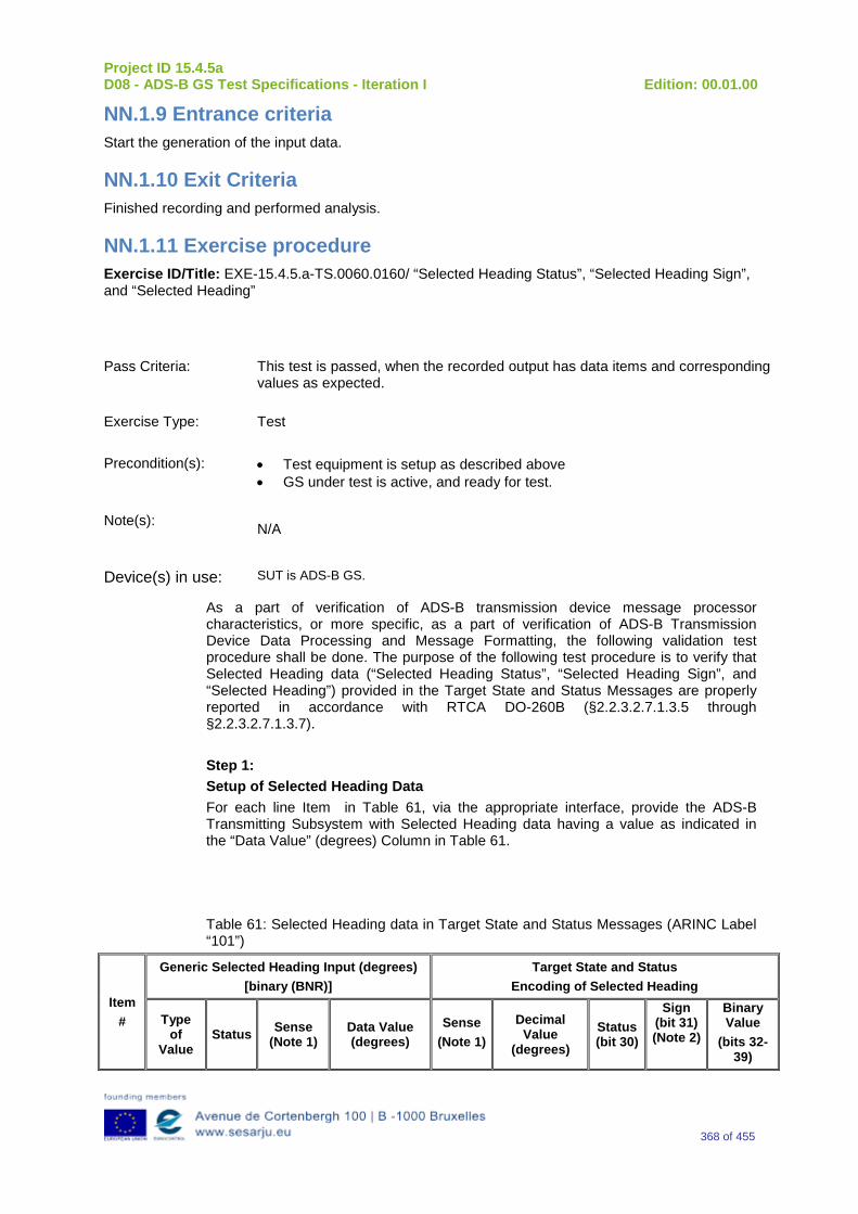
Project ID 15.4.5a D08 - ADS-B GS Test Specifications - Iteration I Edition: 00.01.00
368 of 455
NN.1.9 Entrance criteria Start the generation of the input data.
NN.1.10 Exit Criteria Finished recording and performed analysis.
NN.1.11 Exercise procedure Exercise ID/Title: EXE-15.4.5.a-TS.0060.0160/ “Selected Heading Status”, “Selected Heading Sign”, and “Selected Heading”
Pass Criteria: This test is passed, when the recorded output has data items and corresponding values as expected.
Exercise Type: Test
Precondition(s): • Test equipment is setup as described above • GS under test is active, and ready for test.
Note(s): N/A
Device(s) in use: SUT is ADS-B GS.
As a part of verification of ADS-B transmission device message processor characteristics, or more specific, as a part of verification of ADS-B Transmission Device Data Processing and Message Formatting, the following validation test procedure shall be done. The purpose of the following test procedure is to verify that Selected Heading data (“Selected Heading Status”, “Selected Heading Sign”, and “Selected Heading”) provided in the Target State and Status Messages are properly reported in accordance with RTCA DO-260B (§2.2.3.2.7.1.3.5 through §2.2.3.2.7.1.3.7). Step 1: Setup of Selected Heading Data For each line Item in Table 61, via the appropriate interface, provide the ADS-B Transmitting Subsystem with Selected Heading data having a value as indicated in the “Data Value” (degrees) Column in Table 61. Table 61: Selected Heading data in Target State and Status Messages (ARINC Label “101”)
Item #
Generic Selected Heading Input (degrees) [binary (BNR)]
Target State and Status Encoding of Selected Heading
Type of
Value Status Sense
(Note 1) Data Value (degrees)
Sense (Note 1)
Decimal Value
(degrees) Status (bit 30)
Sign (bit 31) (Note 2)
Binary Value
(bits 32-39)
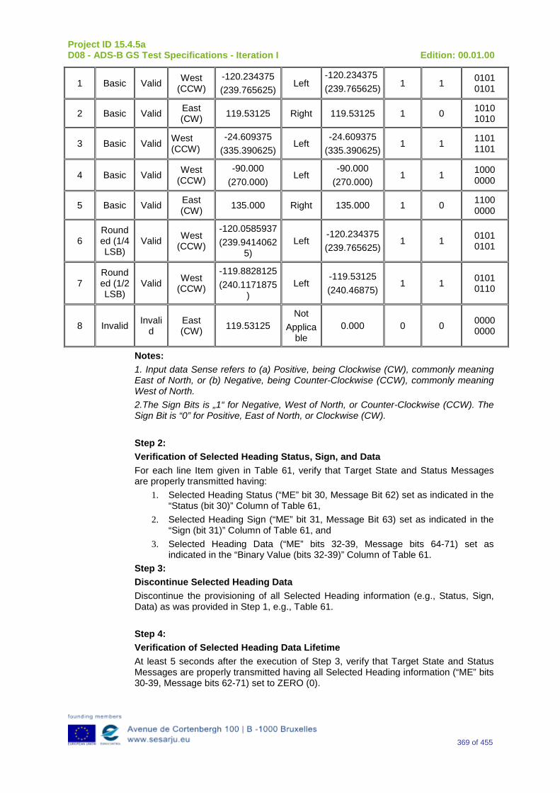
Project ID 15.4.5a D08 - ADS-B GS Test Specifications - Iteration I Edition: 00.01.00
369 of 455
1 Basic Valid West (CCW)
-120.234375 (239.765625)
Left -120.234375 (239.765625) 1 1 0101
0101
2 Basic Valid East (CW) 119.53125 Right 119.53125 1 0 1010
1010
3 Basic Valid West (CCW)
-24.609375 (335.390625)
Left -24.609375
(335.390625) 1 1 1101
1101
4 Basic Valid West (CCW)
-90.000 (270.000)
Left -90.000
(270.000) 1 1 1000
0000
5 Basic Valid East (CW) 135.000 Right 135.000 1 0 1100
0000
6 Rounded (1/4 LSB)
Valid West (CCW)
-120.0585937 (239.9414062
5) Left
-120.234375 (239.765625)
1 1 0101 0101
7 Rounded (1/2 LSB)
Valid West (CCW)
-119.8828125 (240.1171875
) Left
-119.53125 (240.46875)
1 1 0101 0110
8 Invalid Invalid
East (CW) 119.53125
Not Applica
ble 0.000 0 0 0000
0000
Notes: 1. Input data Sense refers to (a) Positive, being Clockwise (CW), commonly meaning East of North, or (b) Negative, being Counter-Clockwise (CCW), commonly meaning West of North. 2.The Sign Bits is „1“ for Negative, West of North, or Counter-Clockwise (CCW). The Sign Bit is “0” for Positive, East of North, or Clockwise (CW). Step 2: Verification of Selected Heading Status, Sign, and Data For each line Item given in Table 61, verify that Target State and Status Messages are properly transmitted having:
1. Selected Heading Status (“ME” bit 30, Message Bit 62) set as indicated in the “Status (bit 30)” Column of Table 61,
2. Selected Heading Sign (“ME” bit 31, Message Bit 63) set as indicated in the “Sign (bit 31)” Column of Table 61, and
3. Selected Heading Data (“ME” bits 32-39, Message bits 64-71) set as indicated in the “Binary Value (bits 32-39)” Column of Table 61.
Step 3: Discontinue Selected Heading Data Discontinue the provisioning of all Selected Heading information (e.g., Status, Sign, Data) as was provided in Step 1, e.g., Table 61. Step 4: Verification of Selected Heading Data Lifetime At least 5 seconds after the execution of Step 3, verify that Target State and Status Messages are properly transmitted having all Selected Heading information (“ME” bits 30-39, Message bits 62-71) set to ZERO (0).
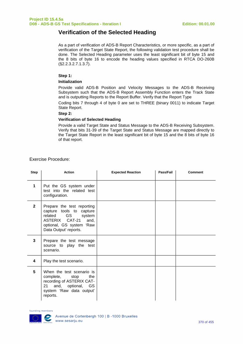
Project ID 15.4.5a D08 - ADS-B GS Test Specifications - Iteration I Edition: 00.01.00
370 of 455
Verification of the Selected Heading As a part of verification of ADS-B Report Characteristics, or more specific, as a part of verification of the Target State Report, the following validation test procedure shall be done. The Selected Heading parameter uses the least significant bit of byte 15 and the 8 bits of byte 16 to encode the heading values specified in RTCA DO-260B (§2.2.3.2.7.1.3.7). Step 1: Initialization Provide valid ADS-B Position and Velocity Messages to the ADS-B Receiving Subsystem such that the ADS-B Report Assembly Function enters the Track State and is outputting Reports to the Report Buffer. Verify that the Report Type Coding bits 7 through 4 of byte 0 are set to THREE (binary 0011) to indicate Target State Report. Step 2: Verification of Selected Heading Provide a valid Target State and Status Message to the ADS-B Receiving Subsystem. Verify that bits 31-39 of the Target State and Status Message are mapped directly to the Target State Report in the least significant bit of byte 15 and the 8 bits of byte 16 of that report.
Exercise Procedure:
Step Action Expected Reaction Pass/Fail Comment
1 Put the GS system under test into the related test configuration.
2 Prepare the test reporting capture tools to capture related GS system ASTERIX CAT-21 and, optional, GS system ‘Raw Data Output’ reports.
3 Prepare the test message source to play the test scenario.
4 Play the test scenario.
5 When the test scenario is complete, stop the recording of ASTERIX CAT-21 and, optional, GS system ‘Raw data output’ reports.
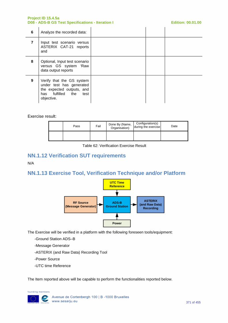
Project ID 15.4.5a D08 - ADS-B GS Test Specifications - Iteration I Edition: 00.01.00
371 of 455
6 Analyze the recorded data:
7 Input test scenario versus ASTERIX CAT-21 reports and
8 Optional, Input test scenario versus GS system ‘Raw data output reports
9 Verify that the GS system under test has generated the expected outputs, and has fulfilled the test objective.
Exercise result:
Pass Fail Done By (Name, Organisation)
Configuration(s) during the exercise Date
Table 62: Verification Exercise Result
NN.1.12 Verification SUT requirements N/A
NN.1.13 Exercise Tool, Verification Technique and/or Platform
ADS-BGround Station
Power
ASTERIX(and Raw Data)
Recording
UTC Time Reference
RF Source(Message Generator)
The Exercise will be verified in a platform with the following foreseen tools/equipment:
-Ground Station ADS–B
-Message Generator
-ASTERIX (and Raw Data) Recording Tool
-Power Source
-UTC time Reference
The Item reported above will be capable to perform the functionalities reported below.
Project ID 15.4.5a D08 - ADS-B GS Test Specifications - Iteration I Edition: 00.01.00
372 of 455
Ground Station ADS-B
The primary function of the 1090 GS is to receive 1090 MHz Mode S Extended Squitter messages, extract the data contained therein, and create appropriated ASTERIX Category 21 and 23 Reports (and optionally, Raw Data).
Message Generator
The Messages Generator will be capable to generate the data coming from the Remote System (ADS–B Ground Station or 1090 Receiver) like:
•Target data stream with inside the information extracted by the ADS–B message (ASTERIX CAT 21 in the case of Ground Station or Raw Data in the case that remote system is a 1090 MHz Receiver).
•Operational Data Stream with inside the Remote System’s Operational Status Information (ASTERIX CAT 23 in the case of Ground Station or Raw Data in the case that remote system is a 1090 MHz Receiver).
UTC Time Reference
The UTC Time reference is the solution adopted in the Test Scenario in order to provide the Synchronization in the Ground Station by UTC Time.
ASTERIX Recording Equipment
The ASTERIX recording equipment will be capable to record all ASTERIX reports sent from the 1090 ES Ground Station.
NN.1.14 Verification Platform needs See section 3.5 Verification Platform Needs.
NN.1.15 Platform Configuration N/A
NN.1.16 Configuration(s) Identification of the Verification Platform N/A
NN.1.17 Links to other Verification Exercises N/A
NN.1.18 Representatively level/ limitations N/A
NN.2 Exercises Planning and management
NN.2.1 Activities N/A
NN.2.1.1 Preparatory activities Setup the tools/equipment listed in 3.5 and NN.1.13 in order to meet the Test Preconditions.
Project ID 15.4.5a D08 - ADS-B GS Test Specifications - Iteration I Edition: 00.01.00
373 of 455
NN.2.1.2 Execution activities Play the scenario generating in the input the desired messages and record the relevant ASTERIX (and Raw Data) output.
NN.2.1.3 Post execution activities The post execution activities will be mainly focused on the analysis of recorded ASTERIX reports (and Raw Data reports). The analysis shall be done in order to verify the right information propagation as requested in each Test Scenario.
NN.2.2 Human Resources N/A
NN.2.3 Responsibilities in the exercise N/A
NN.2.4 Training N/A
NN.2.5 Time planning N/A
NN.2.6 Risks N/A
NN.2.7 Errors and Observation handling N/A
NN.3 Analysis Specification
NN.3.1 Data collection methods The data collection during the test will be Qualitative. In fact after test execution the analysis of ASTERIX Data will be performed verifying that the values reported in the output are in line with the values generated in the input.
NN.3.2 Analysis method N/A
NN.3.3 Data logging requirements The data logging requirements for this scenario will foresee at least ASTERIX CAT 21 items.

Project ID 15.4.5a D08 - ADS-B GS Test Specifications - Iteration I Edition: 00.01.00
374 of 455
Appendix OO Verification Exercise EXE-15.04.05.a-TS.0060.0170 GS: “MCP/FCU Selected Altitude or FMS Selected Altitude” Subfield in Target State and Status Messages
OO.1 Exercise Scope and Justification
OO.1.1 Exercise Level The level of the exercise is functional.
OO.1.2 Exercise Type The type of the exercise is Test.
OO.1.3 Description of the system being addressed ADS – B Ground Station.
OO.1.4 Context of the verification exercise This document is applied to FAT (Factory acceptance Test).
OO.1.5 Required Datasets 1090MHz Extended Squitter Messages input and 1090GS ASTERIX output.
OO.1.6 Verification objectives Verify the Requirements related to the enhancement 1090ES Technology, more specifically, the following requirements:
OBJ-15.04.05.a-TS.0060.0061 The aim of this objective is to check that the ADS–B Surveillance System is capable to decode the ADS-B message, in order to extract the available information, in accordance with the introduced changes in the DO-260B standard.
OBJ-15.04.05.a-TS.0060.0063 The aim of this objective is to check that the ADS-B System ground surveillance domain is able to transform the introduced DO-260B changes into Standard ASTERIX Category 21 data items.
OO.1.7 Inputs 1090MHz Extended Squitter Messages.
OO.1.8 Outputs Recordings of ASTERIX CAT-21 and, optionally, GS system ‘Raw data output’ reports.
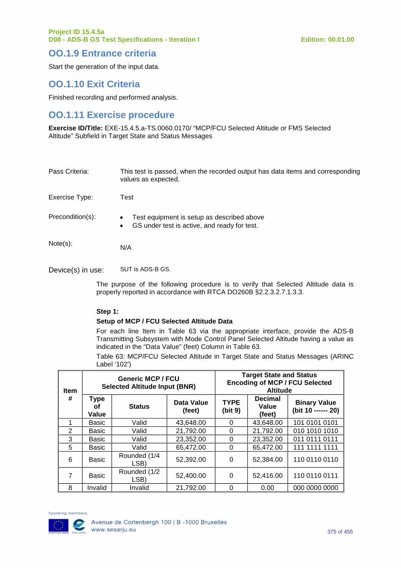
Project ID 15.4.5a D08 - ADS-B GS Test Specifications - Iteration I Edition: 00.01.00
375 of 455
OO.1.9 Entrance criteria Start the generation of the input data.
OO.1.10 Exit Criteria Finished recording and performed analysis.
OO.1.11 Exercise procedure Exercise ID/Title: EXE-15.4.5.a-TS.0060.0170/ “MCP/FCU Selected Altitude or FMS Selected Altitude” Subfield in Target State and Status Messages
Pass Criteria: This test is passed, when the recorded output has data items and corresponding values as expected.
Exercise Type: Test
Precondition(s): • Test equipment is setup as described above • GS under test is active, and ready for test.
Note(s): N/A
Device(s) in use: SUT is ADS-B GS.
The purpose of the following procedure is to verify that Selected Altitude data is properly reported in accordance with RTCA DO260B §2.2.3.2.7.1.3.3. Step 1: Setup of MCP / FCU Selected Altitude Data For each line Item in Table 63 via the appropriate interface, provide the ADS-B Transmitting Subsystem with Mode Control Panel Selected Altitude having a value as indicated in the “Data Value” (feet) Column in Table 63. Table 63: MCP/FCU Selected Altitude in Target State and Status Messages (ARINC Label ‘102’)
Item #
Generic MCP / FCU Selected Altitude Input (BNR)
Target State and Status Encoding of MCP / FCU Selected
Altitude Type
of Value
Status Data Value (feet)
TYPE (bit 9)
Decimal Value (feet)
Binary Value (bit 10 ------ 20)
1 Basic Valid 43,648.00 0 43,648.00 101 0101 0101 2 Basic Valid 21,792.00 0 21,792.00 010 1010 1010 3 Basic Valid 23,352.00 0 23,352.00 011 0111 0111 5 Basic Valid 65,472.00 0 65,472.00 111 1111 1111
6 Basic Rounded (1/4 LSB) 52,392.00 0 52,384.00 110 0110 0110
7 Basic Rounded (1/2 LSB) 52,400.00 0 52,416.00 110 0110 0111
8 Invalid Invalid 21,792.00 0 0.00 000 0000 0000
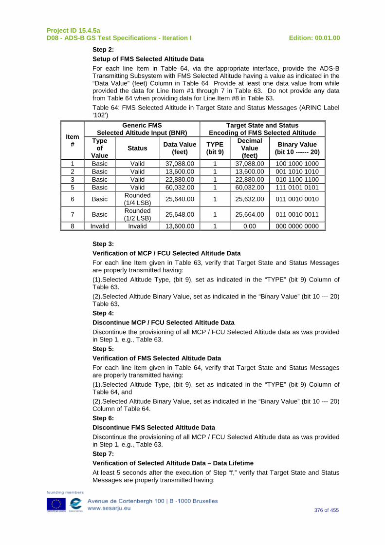
Project ID 15.4.5a D08 - ADS-B GS Test Specifications - Iteration I Edition: 00.01.00
376 of 455
Step 2: Setup of FMS Selected Altitude Data For each line Item in Table 64, via the appropriate interface, provide the ADS-B Transmitting Subsystem with FMS Selected Altitude having a value as indicated in the “Data Value” (feet) Column in Table 64 Provide at least one data value from while provided the data for Line Item #1 through 7 in Table 63. Do not provide any data from Table 64 when providing data for Line Item #8 in Table 63. Table 64: FMS Selected Altitude in Target State and Status Messages (ARINC Label ‘102’)
Item #
Generic FMS Selected Altitude Input (BNR)
Target State and Status Encoding of FMS Selected Altitude
Type of
Value Status Data Value
(feet) TYPE (bit 9)
Decimal Value (feet)
Binary Value (bit 10 ------ 20)
1 Basic Valid 37,088.00 1 37,088.00 100 1000 1000 2 Basic Valid 13,600.00 1 13,600.00 001 1010 1010 3 Basic Valid 22,880.00 1 22,880.00 010 1100 1100 5 Basic Valid 60,032.00 1 60,032.00 111 0101 0101
6 Basic Rounded (1/4 LSB) 25,640.00 1 25,632.00 011 0010 0010
7 Basic Rounded (1/2 LSB) 25,648.00 1 25,664.00 011 0010 0011
8 Invalid Invalid 13,600.00 1 0.00 000 0000 0000
Step 3: Verification of MCP / FCU Selected Altitude Data For each line Item given in Table 63, verify that Target State and Status Messages are properly transmitted having: (1).Selected Altitude Type, (bit 9), set as indicated in the “TYPE” (bit 9) Column of Table 63. (2).Selected Altitude Binary Value, set as indicated in the “Binary Value” (bit 10 --- 20) Table 63. Step 4: Discontinue MCP / FCU Selected Altitude Data Discontinue the provisioning of all MCP / FCU Selected Altitude data as was provided in Step 1, e.g., Table 63. Step 5: Verification of FMS Selected Altitude Data For each line Item given in Table 64, verify that Target State and Status Messages are properly transmitted having: (1).Selected Altitude Type, (bit 9), set as indicated in the “TYPE” (bit 9) Column of Table 64, and (2).Selected Altitude Binary Value, set as indicated in the “Binary Value” (bit 10 --- 20) Column of Table 64. Step 6: Discontinue FMS Selected Altitude Data Discontinue the provisioning of all MCP / FCU Selected Altitude data as was provided in Step 1, e.g., Table 63. Step 7: Verification of Selected Altitude Data – Data Lifetime At least 5 seconds after the execution of Step “f,” verify that Target State and Status Messages are properly transmitted having:
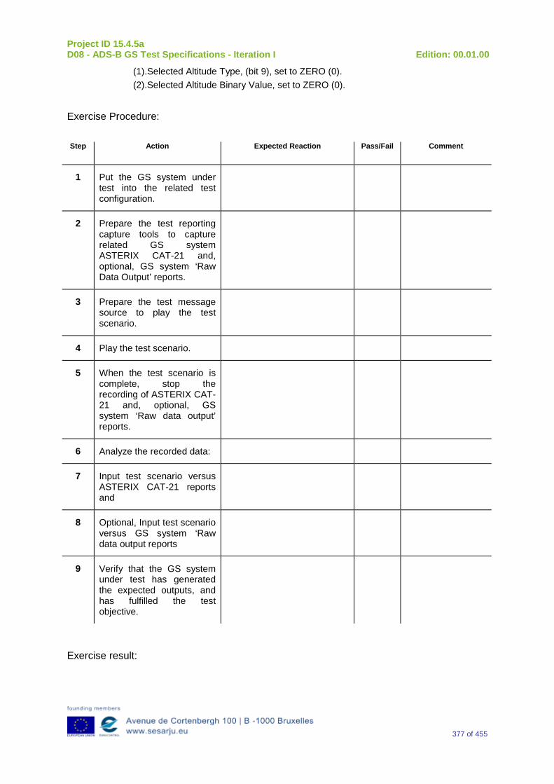
Project ID 15.4.5a D08 - ADS-B GS Test Specifications - Iteration I Edition: 00.01.00
377 of 455
(1).Selected Altitude Type, (bit 9), set to ZERO (0). (2).Selected Altitude Binary Value, set to ZERO (0).
Exercise Procedure:
Step Action Expected Reaction Pass/Fail Comment
1 Put the GS system under test into the related test configuration.
2 Prepare the test reporting capture tools to capture related GS system ASTERIX CAT-21 and, optional, GS system ‘Raw Data Output’ reports.
3 Prepare the test message source to play the test scenario.
4 Play the test scenario.
5 When the test scenario is complete, stop the recording of ASTERIX CAT-21 and, optional, GS system ‘Raw data output’ reports.
6 Analyze the recorded data:
7 Input test scenario versus ASTERIX CAT-21 reports and
8 Optional, Input test scenario versus GS system ‘Raw data output reports
9 Verify that the GS system under test has generated the expected outputs, and has fulfilled the test objective.
Exercise result:

Project ID 15.4.5a D08 - ADS-B GS Test Specifications - Iteration I Edition: 00.01.00
378 of 455
Pass Fail Done By (Name, Organisation)
Configuration(s) during the exercise Date
Table 65: Verification Exercise Result
OO.1.12 Verification SUT requirements N/A
OO.1.13 Exercise Tool, Verification Technique and/or Platform
ADS-BGround Station
Power
ASTERIX(and Raw Data)
Recording
UTC Time Reference
RF Source(Message Generator)
The Exercise will be verified in a platform with the following foreseen tools/equipment:
-Ground Station ADS–B
-Message Generator
-ASTERIX (and Raw Data) Recording Tool
-Power Source
-UTC time Reference
The Item reported above will be capable to perform the functionalities reported below.
Ground Station ADS-B
The primary function of the 1090 GS is to receive 1090 MHz Mode S Extended Squitter messages, extract the data contained therein, and create appropriated ASTERIX Category 21 and 23 Reports (and optionally, Raw Data).
Message Generator
The Messages Generator will be capable to generate the data coming from the Remote System (ADS–B Ground Station or 1090 Receiver) like:
•Target data stream with inside the information extracted by the ADS–B message (ASTERIX CAT 21 in the case of Ground Station or Raw Data in the case that remote system is a 1090 MHz Receiver).
•Operational Data Stream with inside the Remote System’s Operational Status Information (ASTERIX CAT 23 in the case of Ground Station or Raw Data in the case that remote system is a 1090 MHz Receiver).
UTC Time Reference
The UTC Time reference is the solution adopted in the Test Scenario in order to provide the Synchronization in the Ground Station by UTC Time.

Project ID 15.4.5a D08 - ADS-B GS Test Specifications - Iteration I Edition: 00.01.00
379 of 455
ASTERIX Recording Equipment
The ASTERIX recording equipment will be capable to record all ASTERIX reports sent from the 1090 ES Ground Station.
OO.1.14 Verification Platform needs See section 3.5 Verification Platform Needs.
OO.1.15 Platform Configuration N/A
OO.1.16 Configuration(s) Identification of the Verification Platform N/A
OO.1.17 Links to other Verification Exercises N/A
OO.1.18 Representatively level/ limitations N/A
OO.2 Exercises Planning and management
OO.2.1 Activities N/A
OO.2.1.1 Preparatory activities Setup the tools/equipment listed in 3.5 and OO.1.13 in order to meet the Test Preconditions.
OO.2.1.2 Execution activities Play the scenario generating in the input the desired messages and record the relevant ASTERIX (and Raw Data) output.
OO.2.1.3 Post execution activities The post execution activities will be mainly focused on the analysis of recorded ASTERIX reports (and Raw Data reports). The analysis shall be done in order to verify the right information propagation as requested in each Test Scenario.
OO.2.2 Human Resources N/A
OO.2.3 Responsibilities in the exercise N/A
OO.2.4 Training N/A

Project ID 15.4.5a D08 - ADS-B GS Test Specifications - Iteration I Edition: 00.01.00
380 of 455
OO.2.5 Time planning N/A
OO.2.6 Risks N/A
OO.2.7 Errors and Observation handling N/A
OO.3 Analysis Specification
OO.3.1 Data collection methods The data collection during the test will be Qualitative. In fact after test execution the analysis of ASTERIX Data will be performed verifying that the values reported in the output are in line with the values generated in the input.
OO.3.2 Analysis method N/A
OO.3.3 Data logging requirements The data logging requirements for this scenario will foresee at least ASTERIX CAT 21 items.
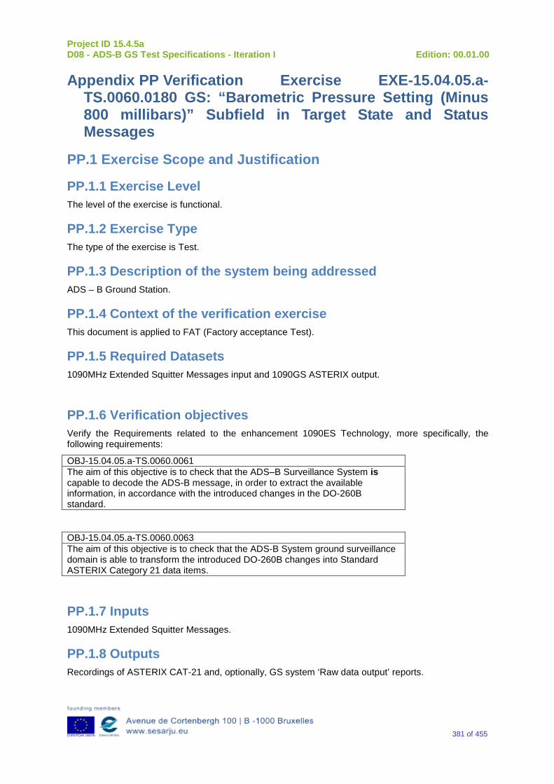
Project ID 15.4.5a D08 - ADS-B GS Test Specifications - Iteration I Edition: 00.01.00
381 of 455
Appendix PP Verification Exercise EXE-15.04.05.a-TS.0060.0180 GS: “Barometric Pressure Setting (Minus 800 millibars)” Subfield in Target State and Status Messages
PP.1 Exercise Scope and Justification
PP.1.1 Exercise Level The level of the exercise is functional.
PP.1.2 Exercise Type The type of the exercise is Test.
PP.1.3 Description of the system being addressed ADS – B Ground Station.
PP.1.4 Context of the verification exercise This document is applied to FAT (Factory acceptance Test).
PP.1.5 Required Datasets 1090MHz Extended Squitter Messages input and 1090GS ASTERIX output.
PP.1.6 Verification objectives Verify the Requirements related to the enhancement 1090ES Technology, more specifically, the following requirements:
OBJ-15.04.05.a-TS.0060.0061 The aim of this objective is to check that the ADS–B Surveillance System is capable to decode the ADS-B message, in order to extract the available information, in accordance with the introduced changes in the DO-260B standard.
OBJ-15.04.05.a-TS.0060.0063 The aim of this objective is to check that the ADS-B System ground surveillance domain is able to transform the introduced DO-260B changes into Standard ASTERIX Category 21 data items.
PP.1.7 Inputs 1090MHz Extended Squitter Messages.
PP.1.8 Outputs Recordings of ASTERIX CAT-21 and, optionally, GS system ‘Raw data output’ reports.
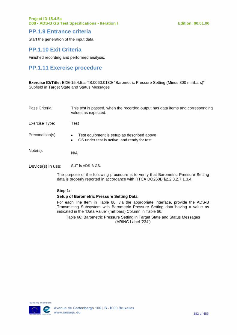
Project ID 15.4.5a D08 - ADS-B GS Test Specifications - Iteration I Edition: 00.01.00
382 of 455
PP.1.9 Entrance criteria Start the generation of the input data.
PP.1.10 Exit Criteria Finished recording and performed analysis.
PP.1.11 Exercise procedure
Exercise ID/Title: EXE-15.4.5.a-TS.0060.0180/ “Barometric Pressure Setting (Minus 800 millibars)” Subfield in Target State and Status Messages
Pass Criteria: This test is passed, when the recorded output has data items and corresponding values as expected.
Exercise Type: Test
Precondition(s): • Test equipment is setup as described above • GS under test is active, and ready for test.
Note(s): N/A
Device(s) in use: SUT is ADS-B GS.
The purpose of the following procedure is to verify that Barometric Pressure Setting data is properly reported in accordance with RTCA DO260B §2.2.3.2.7.1.3.4. Step 1: Setup of Barometric Pressure Setting Data For each line Item in Table 66, via the appropriate interface, provide the ADS-B Transmitting Subsystem with Barometric Pressure Setting data having a value as indicated in the “Data Value” (millibars) Column in Table 66.
Table 66: Barometric Pressure Setting in Target State and Status Messages (ARINC Label ‘234’)
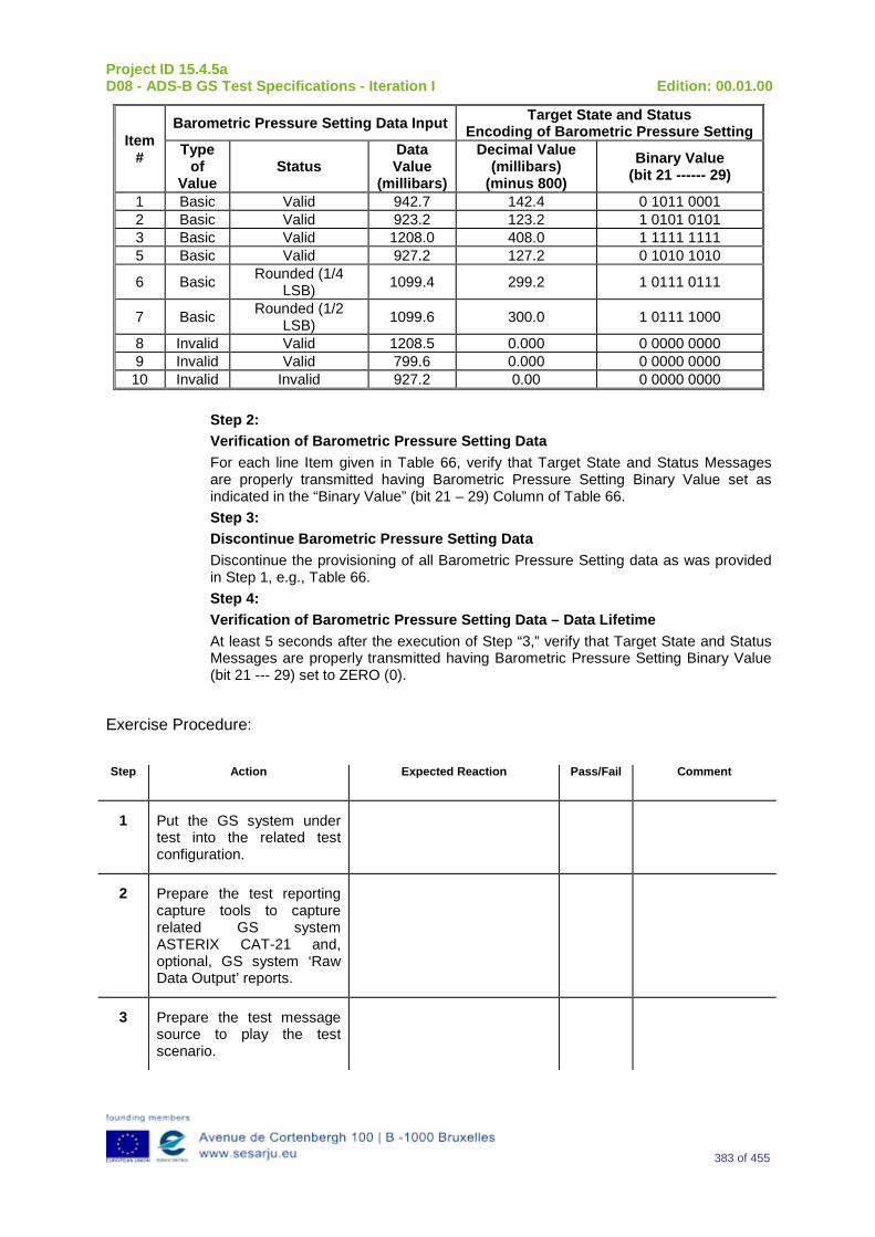
Project ID 15.4.5a D08 - ADS-B GS Test Specifications - Iteration I Edition: 00.01.00
383 of 455
Item #
Barometric Pressure Setting Data Input Target State and Status Encoding of Barometric Pressure Setting
Type of
Value Status
Data Value
(millibars)
Decimal Value (millibars)
(minus 800) Binary Value
(bit 21 ------ 29)
1 Basic Valid 942.7 142.4 0 1011 0001 2 Basic Valid 923.2 123.2 1 0101 0101 3 Basic Valid 1208.0 408.0 1 1111 1111 5 Basic Valid 927.2 127.2 0 1010 1010
6 Basic Rounded (1/4 LSB) 1099.4 299.2 1 0111 0111
7 Basic Rounded (1/2 LSB) 1099.6 300.0 1 0111 1000
8 Invalid Valid 1208.5 0.000 0 0000 0000 9 Invalid Valid 799.6 0.000 0 0000 0000 10 Invalid Invalid 927.2 0.00 0 0000 0000
Step 2: Verification of Barometric Pressure Setting Data For each line Item given in Table 66, verify that Target State and Status Messages are properly transmitted having Barometric Pressure Setting Binary Value set as indicated in the “Binary Value” (bit 21 – 29) Column of Table 66. Step 3: Discontinue Barometric Pressure Setting Data Discontinue the provisioning of all Barometric Pressure Setting data as was provided in Step 1, e.g., Table 66. Step 4: Verification of Barometric Pressure Setting Data – Data Lifetime At least 5 seconds after the execution of Step “3,” verify that Target State and Status Messages are properly transmitted having Barometric Pressure Setting Binary Value (bit 21 --- 29) set to ZERO (0).
Exercise Procedure:
Step Action Expected Reaction Pass/Fail Comment
1 Put the GS system under test into the related test configuration.
2 Prepare the test reporting capture tools to capture related GS system ASTERIX CAT-21 and, optional, GS system ‘Raw Data Output’ reports.
3 Prepare the test message source to play the test scenario.
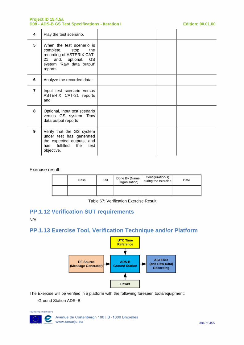
Project ID 15.4.5a D08 - ADS-B GS Test Specifications - Iteration I Edition: 00.01.00
384 of 455
4 Play the test scenario.
5 When the test scenario is complete, stop the recording of ASTERIX CAT-21 and, optional, GS system ‘Raw data output’ reports.
6 Analyze the recorded data:
7 Input test scenario versus ASTERIX CAT-21 reports and
8 Optional, Input test scenario versus GS system ‘Raw data output reports
9 Verify that the GS system under test has generated the expected outputs, and has fulfilled the test objective.
Exercise result:
Pass Fail Done By (Name, Organisation)
Configuration(s) during the exercise Date
Table 67: Verification Exercise Result
PP.1.12 Verification SUT requirements N/A
PP.1.13 Exercise Tool, Verification Technique and/or Platform
ADS-BGround Station
Power
ASTERIX(and Raw Data)
Recording
UTC Time Reference
RF Source(Message Generator)
The Exercise will be verified in a platform with the following foreseen tools/equipment:
-Ground Station ADS–B
Project ID 15.4.5a D08 - ADS-B GS Test Specifications - Iteration I Edition: 00.01.00
385 of 455
-Message Generator
-ASTERIX (and Raw Data) Recording Tool
-Power Source
-UTC time Reference
The Item reported above will be capable to perform the functionalities reported below.
Ground Station ADS-B
The primary function of the 1090 GS is to receive 1090 MHz Mode S Extended Squitter messages, extract the data contained therein, and create appropriated ASTERIX Category 21 and 23 Reports (and optionally, Raw Data).
Message Generator
The Messages Generator will be capable to generate the data coming from the Remote System (ADS–B Ground Station or 1090 Receiver) like:
•Target data stream with inside the information extracted by the ADS–B message (ASTERIX CAT 21 in the case of Ground Station or Raw Data in the case that remote system is a 1090 MHz Receiver).
•Operational Data Stream with inside the Remote System’s Operational Status Information (ASTERIX CAT 23 in the case of Ground Station or Raw Data in the case that remote system is a 1090 MHz Receiver).
UTC Time Reference
The UTC Time reference is the solution adopted in the Test Scenario in order to provide the Synchronization in the Ground Station by UTC Time.
ASTERIX Recording Equipment
The ASTERIX recording equipment will be capable to record all ASTERIX reports sent from the 1090 ES Ground Station.
PP.1.14 Verification Platform needs See section 3.5 Verification Platform Needs.
PP.1.15 Platform Configuration N/A
PP.1.16 Configuration(s) Identification of the Verification Platform N/A
PP.1.17 Links to other Verification Exercises N/A
PP.1.18 Representatively level/ limitations N/A
Project ID 15.4.5a D08 - ADS-B GS Test Specifications - Iteration I Edition: 00.01.00
386 of 455
PP.2 Exercises Planning and management
PP.2.1 Activities N/A
PP.2.1.1 Preparatory activities Setup the tools/equipment listed in 3.5 and PP.1.13 in order to meet the Test Preconditions.
PP.2.1.2 Execution activities Play the scenario generating in the input the desired messages and record the relevant ASTERIX (and Raw Data) output.
PP.2.1.3 Post execution activities The post execution activities will be mainly focused on the analysis of recorded ASTERIX reports (and Raw Data reports). The analysis shall be done in order to verify the right information propagation as requested in each Test Scenario.
PP.2.2 Human Resources N/A
PP.2.3 Responsibilities in the exercise N/A
PP.2.4 Training N/A
PP.2.5 Time planning N/A
PP.2.6 Risks N/A
PP.2.7 Errors and Observation handling N/A
PP.3 Analysis Specification
PP.3.1 Data collection methods The data collection during the test will be Qualitative. In fact after test execution the analysis of ASTERIX Data will be performed verifying that the values reported in the output are in line with the values generated in the input.
PP.3.2 Analysis method N/A

Project ID 15.4.5a D08 - ADS-B GS Test Specifications - Iteration I Edition: 00.01.00
387 of 455
PP.3.3 Data logging requirements The data logging requirements for this scenario will foresee at least ASTERIX CAT 21 items.
Project ID 15.4.5a D08 - ADS-B GS Test Specifications - Iteration I Edition: 00.01.00
388 of 455
Appendix QQ Verification Exercise EXE-15.04.05.a-TS.0060.0190 GS: “Status of MCP/FCU Mode Bits” Subfield in Target State and Status Messages
QQ.1Exercise Scope and Justification
QQ.1.1 Exercise Level The level of the exercise is functional.
QQ.1.2 Exercise Type The type of the exercise is Test.
QQ.1.3 Description of the system being addressed ADS – B Ground Station.
QQ.1.4 Context of the verification exercise This document is applied to FAT (Factory acceptance Test).
QQ.1.5 Required Datasets 1090MHz Extended Squitter Messages input and 1090GS ASTERIX output.
QQ.1.6 Verification objectives Verify the Requirements related to the enhancement 1090ES Technology, more specifically, the following requirements:
OBJ-15.04.05.a-TS.0060.0061 The aim of this objective is to check that the ADS–B Surveillance System is capable to decode the ADS-B message, in order to extract the available information, in accordance with the introduced changes in the DO-260B standard.
OBJ-15.04.05.a-TS.0060.0063 The aim of this objective is to check that the ADS-B System ground surveillance domain is able to transform the introduced DO-260B changes into Standard ASTERIX Category 21 data items.
QQ.1.7 Inputs 1090MHz Extended Squitter Messages.
QQ.1.8 Outputs Recordings of ASTERIX CAT-21 and, optionally, GS system ‘Raw data output’ reports.
Project ID 15.4.5a D08 - ADS-B GS Test Specifications - Iteration I Edition: 00.01.00
389 of 455
QQ.1.9 Entrance criteria Start the generation of the input data.
QQ.1.10 Exit Criteria Finished recording and performed analysis.
QQ.1.11 Exercise procedure
Exercise ID/Title: EXE-15.4.5.a-TS.0060.0190/ “Status of MCP/FCU Mode Bits” Subfield in Target State and Status Messages
Pass Criteria: This test is passed, when the recorded output has data items and corresponding values as expected.
Exercise Type: Test
Precondition(s): • Test equipment is setup as described above • GS under test is active, and ready for test.
Note(s): N/A
Device(s) in use: SUT is ADS-B GS.
The purpose of the following test procedure is to verify that “Status of MCP / FCU Mode Bits” information is properly reported in accordance with RTCA DO260B §2.2.3.2.7.1.3.11. Step 1: Initialization with NO Status Ensure that No information is being provided to the ADS-B Transmitting Subsystem that would indicate the status of Autopilot Engaged, VNAV Mode Engaged, Altitude Hold Mode, Approach Mode or LNAV Mode Engaged. Step 2: Verification of NO Status Verify that Target State and Status Messages are properly transmitted having the “Status of MCP / FCU Mode Bits” subfield (“ME” bit 47, Message bit 79) set to ZERO (0). Step 3: Initialization with Status Via the appropriate interface(s), provide the ADS-B Transmit Subsystem with the status of Autopilot Engaged, VNAV Mode Engaged, Altitude Hold Mode Approach Mode and LNAV Mode Engaged, with the status indicating “Not Engaged” for each of the status parameters. Step 4: Verification of Provided Status
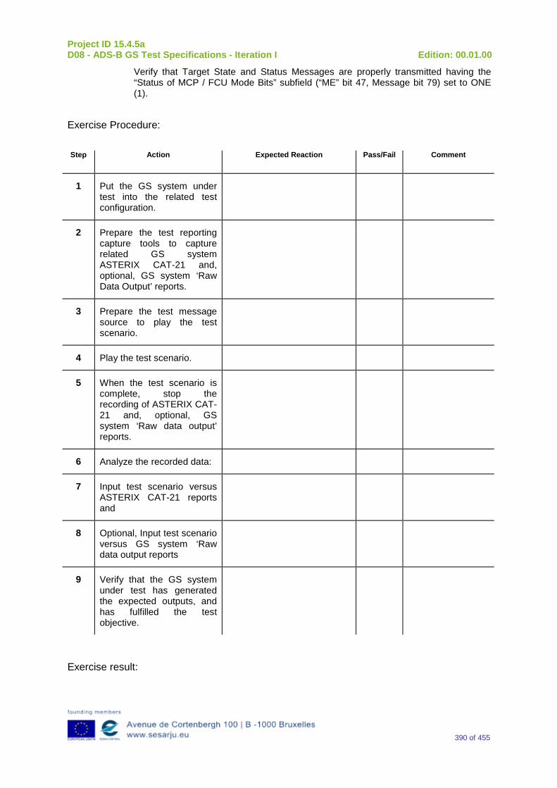
Project ID 15.4.5a D08 - ADS-B GS Test Specifications - Iteration I Edition: 00.01.00
390 of 455
Verify that Target State and Status Messages are properly transmitted having the “Status of MCP / FCU Mode Bits” subfield (“ME” bit 47, Message bit 79) set to ONE (1).
Exercise Procedure:
Step Action Expected Reaction Pass/Fail Comment
1 Put the GS system under test into the related test configuration.
2 Prepare the test reporting capture tools to capture related GS system ASTERIX CAT-21 and, optional, GS system ‘Raw Data Output’ reports.
3 Prepare the test message source to play the test scenario.
4 Play the test scenario.
5 When the test scenario is complete, stop the recording of ASTERIX CAT-21 and, optional, GS system ‘Raw data output’ reports.
6 Analyze the recorded data:
7 Input test scenario versus ASTERIX CAT-21 reports and
8 Optional, Input test scenario versus GS system ‘Raw data output reports
9 Verify that the GS system under test has generated the expected outputs, and has fulfilled the test objective.
Exercise result:
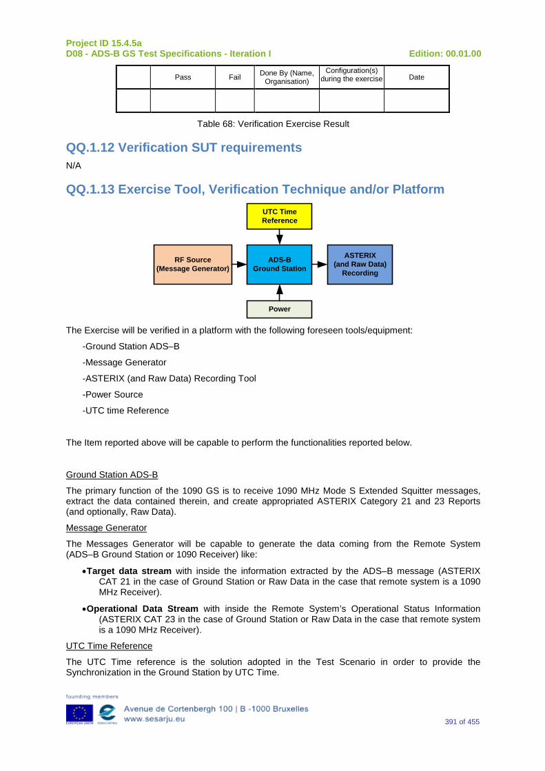
Project ID 15.4.5a D08 - ADS-B GS Test Specifications - Iteration I Edition: 00.01.00
391 of 455
Pass Fail Done By (Name, Organisation)
Configuration(s) during the exercise Date
Table 68: Verification Exercise Result
QQ.1.12 Verification SUT requirements N/A
QQ.1.13 Exercise Tool, Verification Technique and/or Platform
ADS-BGround Station
Power
ASTERIX(and Raw Data)
Recording
UTC Time Reference
RF Source(Message Generator)
The Exercise will be verified in a platform with the following foreseen tools/equipment:
-Ground Station ADS–B
-Message Generator
-ASTERIX (and Raw Data) Recording Tool
-Power Source
-UTC time Reference
The Item reported above will be capable to perform the functionalities reported below.
Ground Station ADS-B
The primary function of the 1090 GS is to receive 1090 MHz Mode S Extended Squitter messages, extract the data contained therein, and create appropriated ASTERIX Category 21 and 23 Reports (and optionally, Raw Data).
Message Generator
The Messages Generator will be capable to generate the data coming from the Remote System (ADS–B Ground Station or 1090 Receiver) like:
•Target data stream with inside the information extracted by the ADS–B message (ASTERIX CAT 21 in the case of Ground Station or Raw Data in the case that remote system is a 1090 MHz Receiver).
•Operational Data Stream with inside the Remote System’s Operational Status Information (ASTERIX CAT 23 in the case of Ground Station or Raw Data in the case that remote system is a 1090 MHz Receiver).
UTC Time Reference
The UTC Time reference is the solution adopted in the Test Scenario in order to provide the Synchronization in the Ground Station by UTC Time.

Project ID 15.4.5a D08 - ADS-B GS Test Specifications - Iteration I Edition: 00.01.00
392 of 455
ASTERIX Recording Equipment
The ASTERIX recording equipment will be capable to record all ASTERIX reports sent from the 1090 ES Ground Station.
QQ.1.14 Verification Platform needs See section 3.5 Verification Platform Needs.
QQ.1.15 Platform Configuration N/A
QQ.1.16 Configuration(s) Identification of the Verification Platform N/A
QQ.1.17 Links to other Verification Exercises N/A
QQ.1.18 Representatively level/ limitations N/A
QQ.2 Exercises Planning and management
QQ.2.1 Activities N/A
QQ.2.1.1 Preparatory activities Setup the tools/equipment listed in 3.5 and QQ.1.13 in order to meet the Test Preconditions.
QQ.2.1.2 Execution activities Play the scenario generating in the input the desired messages and record the relevant ASTERIX (and Raw Data) output.
QQ.2.1.3 Post execution activities The post execution activities will be mainly focused on the analysis of recorded ASTERIX reports (and Raw Data reports). The analysis shall be done in order to verify the right information propagation as requested in each Test Scenario.
QQ.2.2 Human Resources N/A
QQ.2.3 Responsibilities in the exercise N/A
QQ.2.4 Training N/A
Project ID 15.4.5a D08 - ADS-B GS Test Specifications - Iteration I Edition: 00.01.00
393 of 455
QQ.2.5 Time planning N/A
QQ.2.6 Risks N/A
QQ.2.7 Errors and Observation handling N/A
QQ.3 Analysis Specification
QQ.3.1 Data collection methods The data collection during the test will be Qualitative. In fact after test execution the analysis of ASTERIX Data will be performed verifying that the values reported in the output are in line with the values generated in the input.
QQ.3.2 Analysis method N/A
QQ.3.3 Data logging requirements The data logging requirements for this scenario will foresee at least ASTERIX CAT 21 items.
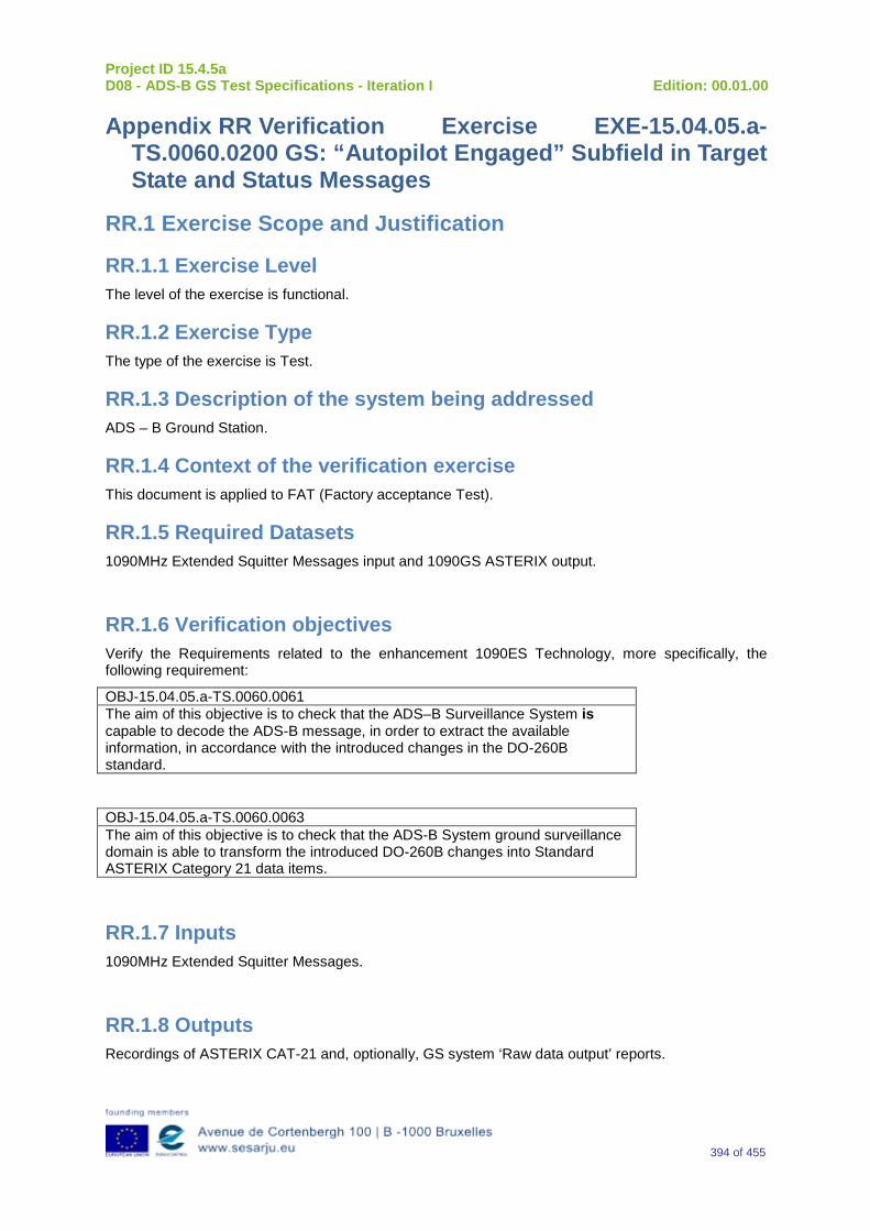
Project ID 15.4.5a D08 - ADS-B GS Test Specifications - Iteration I Edition: 00.01.00
394 of 455
Appendix RR Verification Exercise EXE-15.04.05.a-TS.0060.0200 GS: “Autopilot Engaged” Subfield in Target State and Status Messages
RR.1 Exercise Scope and Justification
RR.1.1 Exercise Level The level of the exercise is functional.
RR.1.2 Exercise Type The type of the exercise is Test.
RR.1.3 Description of the system being addressed ADS – B Ground Station.
RR.1.4 Context of the verification exercise This document is applied to FAT (Factory acceptance Test).
RR.1.5 Required Datasets 1090MHz Extended Squitter Messages input and 1090GS ASTERIX output.
RR.1.6 Verification objectives Verify the Requirements related to the enhancement 1090ES Technology, more specifically, the following requirement:
OBJ-15.04.05.a-TS.0060.0061 The aim of this objective is to check that the ADS–B Surveillance System is capable to decode the ADS-B message, in order to extract the available information, in accordance with the introduced changes in the DO-260B standard.
OBJ-15.04.05.a-TS.0060.0063 The aim of this objective is to check that the ADS-B System ground surveillance domain is able to transform the introduced DO-260B changes into Standard ASTERIX Category 21 data items.
RR.1.7 Inputs 1090MHz Extended Squitter Messages.
RR.1.8 Outputs Recordings of ASTERIX CAT-21 and, optionally, GS system ‘Raw data output’ reports.
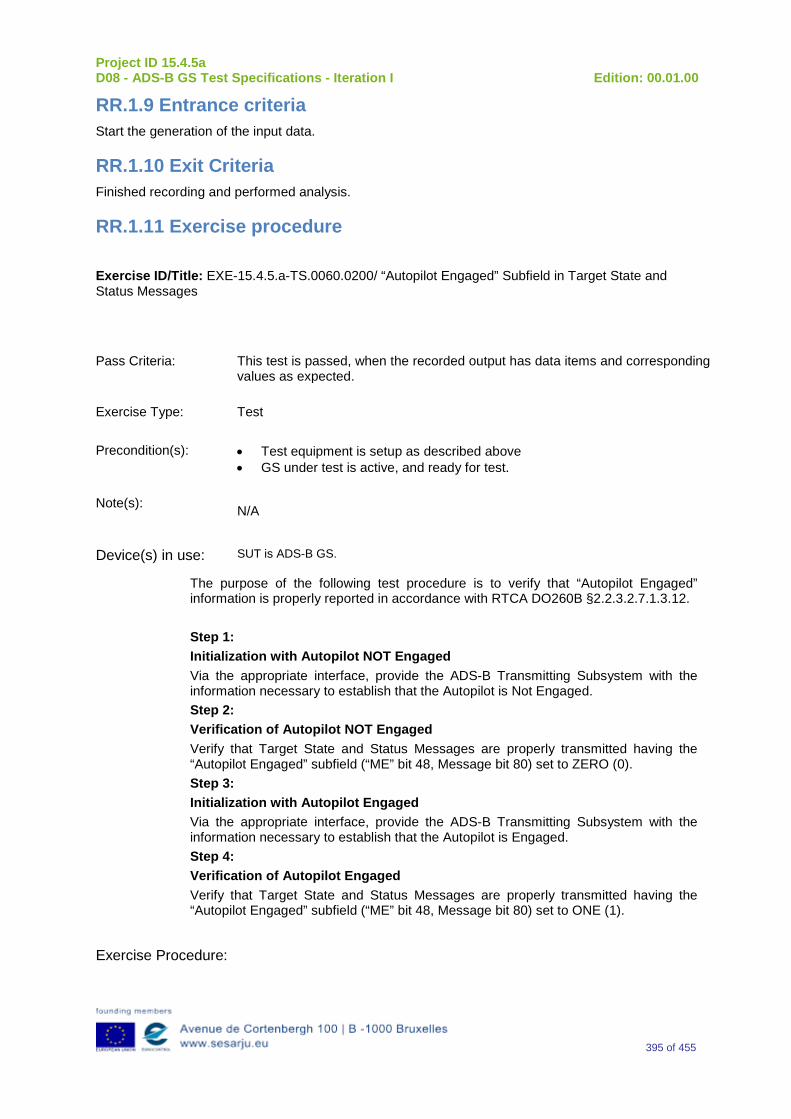
Project ID 15.4.5a D08 - ADS-B GS Test Specifications - Iteration I Edition: 00.01.00
395 of 455
RR.1.9 Entrance criteria Start the generation of the input data.
RR.1.10 Exit Criteria Finished recording and performed analysis.
RR.1.11 Exercise procedure
Exercise ID/Title: EXE-15.4.5.a-TS.0060.0200/ “Autopilot Engaged” Subfield in Target State and Status Messages
Pass Criteria: This test is passed, when the recorded output has data items and corresponding values as expected.
Exercise Type: Test
Precondition(s): • Test equipment is setup as described above • GS under test is active, and ready for test.
Note(s): N/A
Device(s) in use: SUT is ADS-B GS.
The purpose of the following test procedure is to verify that “Autopilot Engaged” information is properly reported in accordance with RTCA DO260B §2.2.3.2.7.1.3.12. Step 1: Initialization with Autopilot NOT Engaged Via the appropriate interface, provide the ADS-B Transmitting Subsystem with the information necessary to establish that the Autopilot is Not Engaged. Step 2: Verification of Autopilot NOT Engaged Verify that Target State and Status Messages are properly transmitted having the “Autopilot Engaged” subfield (“ME” bit 48, Message bit 80) set to ZERO (0). Step 3: Initialization with Autopilot Engaged Via the appropriate interface, provide the ADS-B Transmitting Subsystem with the information necessary to establish that the Autopilot is Engaged. Step 4: Verification of Autopilot Engaged Verify that Target State and Status Messages are properly transmitted having the “Autopilot Engaged” subfield (“ME” bit 48, Message bit 80) set to ONE (1).
Exercise Procedure:

Project ID 15.4.5a D08 - ADS-B GS Test Specifications - Iteration I Edition: 00.01.00
396 of 455
Step Action Expected Reaction Pass/Fail Comment
1 Put the GS system under test into the related test configuration.
2 Prepare the test reporting capture tools to capture related GS system ASTERIX CAT-21 and, optional, GS system ‘Raw Data Output’ reports.
3 Prepare the test message source to play the test scenario.
4 Play the test scenario.
5 When the test scenario is complete, stop the recording of ASTERIX CAT-21 and, optional, GS system ‘Raw data output’ reports.
6 Analyze the recorded data:
7 Input test scenario versus ASTERIX CAT-21 reports and
8 Optional, Input test scenario versus GS system ‘Raw data output reports
9 Verify that the GS system under test has generated the expected outputs, and has fulfilled the test objective.
Exercise result:
Pass Fail Done By (Name, Organisation)
Configuration(s) during the exercise Date
Table 69: Verification Exercise Result

Project ID 15.4.5a D08 - ADS-B GS Test Specifications - Iteration I Edition: 00.01.00
397 of 455
RR.1.12 Verification SUT requirements N/A
RR.1.13 Exercise Tool, Verification Technique and/or Platform
ADS-BGround Station
Power
ASTERIX(and Raw Data)
Recording
UTC Time Reference
RF Source(Message Generator)
The Exercise will be verified in a platform with the following foreseen tools/equipment:
-Ground Station ADS–B
-Message Generator
-ASTERIX (and Raw Data) Recording Tool
-Power Source
-UTC time Reference
The Item reported above will be capable to perform the functionalities reported below.
Ground Station ADS-B
The primary function of the 1090 GS is to receive 1090 MHz Mode S Extended Squitter messages, extract the data contained therein, and create appropriated ASTERIX Category 21 and 23 Reports (and optionally, Raw Data).
Message Generator
The Messages Generator will be capable to generate the data coming from the Remote System (ADS–B Ground Station or 1090 Receiver) like:
•Target data stream with inside the information extracted by the ADS–B message (ASTERIX CAT 21 in the case of Ground Station or Raw Data in the case that remote system is a 1090 MHz Receiver).
•Operational Data Stream with inside the Remote System’s Operational Status Information (ASTERIX CAT 23 in the case of Ground Station or Raw Data in the case that remote system is a 1090 MHz Receiver).
UTC Time Reference
The UTC Time reference is the solution adopted in the Test Scenario in order to provide the Synchronization in the Ground Station by UTC Time.
ASTERIX Recording Equipment
The ASTERIX recording equipment will be capable to record all ASTERIX reports sent from the 1090 ES Ground Station.

Project ID 15.4.5a D08 - ADS-B GS Test Specifications - Iteration I Edition: 00.01.00
398 of 455
RR.1.14 Verification Platform needs See section 3.5 Verification Platform Needs.
RR.1.15 Platform Configuration N/A
RR.1.16 Configuration(s) Identification of the Verification Platform N/A
RR.1.17 Links to other Verification Exercises N/A
RR.1.18 Representatively level/ limitations N/A
RR.2 Exercises Planning and management
RR.2.1 Activities N/A
RR.2.1.1 Preparatory activities Setup the tools/equipment listed in 3.5 and RR.1.13 in order to meet the Test Preconditions.
RR.2.1.2 Execution activities Play the scenario generating in the input the desired messages and record the relevant ASTERIX (and Raw Data) output.
RR.2.1.3 Post execution activities The post execution activities will be mainly focused on the analysis of recorded ASTERIX reports (and Raw Data reports). The analysis shall be done in order to verify the right information propagation as requested in each Test Scenario.
RR.2.2 Human Resources N/A
RR.2.3 Responsibilities in the exercise N/A
RR.2.4 Training N/A
RR.2.5 Time planning N/A
Project ID 15.4.5a D08 - ADS-B GS Test Specifications - Iteration I Edition: 00.01.00
399 of 455
RR.2.6 Risks N/A
RR.2.7 Errors and Observation handling N/A
RR.3 Analysis Specification
RR.3.1 Data collection methods The data collection during the test will be Qualitative. In fact after test execution the analysis of ASTERIX Data will be performed verifying that the values reported in the output are in line with the values generated in the input.
RR.3.2 Analysis method N/A
RR.3.3 Data logging requirements The data logging requirements for this scenario will foresee at least ASTERIX CAT 21 items.

Project ID 15.4.5a D08 - ADS-B GS Test Specifications - Iteration I Edition: 00.01.00
400 of 455
Appendix SS Verification Exercise EXE-15.04.05.a-TS.0060.0210 GS: “VNAV Mode Engaged” Subfield in Target State and Status Messages
SS.1 Exercise Scope and Justification
SS.1.1 Exercise Level The level of the exercise is functional.
SS.1.2 Exercise Type The type of the exercise is Test.
SS.1.3 Description of the system being addressed ADS – B Ground Station.
SS.1.4 Context of the verification exercise This document is applied to FAT (Factory acceptance Test).
SS.1.5 Required Datasets 1090MHz Extended Squitter Messages input and 1090GS ASTERIX output.
SS.1.6 Verification objectives Verify the Requirements related to the enhancement 1090ES Technology, more specifically, the following requirement:
OBJ-15.04.05.a-TS.0060.0061 The aim of this objective is to check that the ADS–B Surveillance System is capable to decode the ADS-B message, in order to extract the available information, in accordance with the introduced changes in the DO-260B standard.
OBJ-15.04.05.a-TS.0060.0063 The aim of this objective is to check that the ADS-B System ground surveillance domain is able to transform the introduced DO-260B changes into Standard ASTERIX Category 21 data items.
SS.1.7 Inputs 1090MHz Extended Squitter Messages.
SS.1.8 Outputs Recordings of ASTERIX CAT-21 and, optionally, GS system ‘Raw data output’ reports.
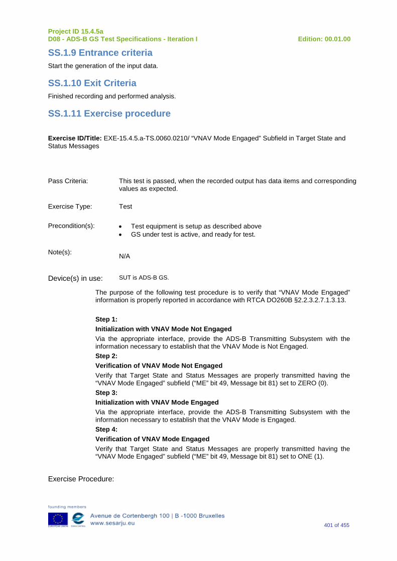
Project ID 15.4.5a D08 - ADS-B GS Test Specifications - Iteration I Edition: 00.01.00
401 of 455
SS.1.9 Entrance criteria Start the generation of the input data.
SS.1.10 Exit Criteria Finished recording and performed analysis.
SS.1.11 Exercise procedure
Exercise ID/Title: EXE-15.4.5.a-TS.0060.0210/ “VNAV Mode Engaged” Subfield in Target State and Status Messages
Pass Criteria: This test is passed, when the recorded output has data items and corresponding values as expected.
Exercise Type: Test
Precondition(s): • Test equipment is setup as described above • GS under test is active, and ready for test.
Note(s): N/A
Device(s) in use: SUT is ADS-B GS.
The purpose of the following test procedure is to verify that “VNAV Mode Engaged” information is properly reported in accordance with RTCA DO260B §2.2.3.2.7.1.3.13. Step 1: Initialization with VNAV Mode Not Engaged Via the appropriate interface, provide the ADS-B Transmitting Subsystem with the information necessary to establish that the VNAV Mode is Not Engaged. Step 2: Verification of VNAV Mode Not Engaged Verify that Target State and Status Messages are properly transmitted having the “VNAV Mode Engaged” subfield (“ME” bit 49, Message bit 81) set to ZERO (0). Step 3: Initialization with VNAV Mode Engaged Via the appropriate interface, provide the ADS-B Transmitting Subsystem with the information necessary to establish that the VNAV Mode is Engaged. Step 4: Verification of VNAV Mode Engaged Verify that Target State and Status Messages are properly transmitted having the “VNAV Mode Engaged” subfield (“ME” bit 49, Message bit 81) set to ONE (1).
Exercise Procedure:

Project ID 15.4.5a D08 - ADS-B GS Test Specifications - Iteration I Edition: 00.01.00
402 of 455
Step Action Expected Reaction Pass/Fail Comment
1 Put the GS system under test into the related test configuration.
2 Prepare the test reporting capture tools to capture related GS system ASTERIX CAT-21 and, optional, GS system ‘Raw Data Output’ reports.
3 Prepare the test message source to play the test scenario.
4 Play the test scenario.
5 When the test scenario is complete, stop the recording of ASTERIX CAT-21 and, optional, GS system ‘Raw data output’ reports.
6 Analyze the recorded data:
7 Input test scenario versus ASTERIX CAT-21 reports and
8 Optional, Input test scenario versus GS system ‘Raw data output reports
9 Verify that the GS system under test has generated the expected outputs, and has fulfilled the test objective.
Exercise result:
Pass Fail Done By (Name, Organisation)
Configuration(s) during the exercise Date
Table 70: Verification Exercise Result

Project ID 15.4.5a D08 - ADS-B GS Test Specifications - Iteration I Edition: 00.01.00
403 of 455
SS.1.12 Verification SUT requirements N/A
SS.1.13 Exercise Tool, Verification Technique and/or Platform
ADS-BGround Station
Power
ASTERIX(and Raw Data)
Recording
UTC Time Reference
RF Source(Message Generator)
The Exercise will be verified in a platform with the following foreseen tools/equipment:
-Ground Station ADS–B
-Message Generator
-ASTERIX (and Raw Data) Recording Tool
-Power Source
-UTC time Reference
The Item reported above will be capable to perform the functionalities reported below.
Ground Station ADS-B
The primary function of the 1090 GS is to receive 1090 MHz Mode S Extended Squitter messages, extract the data contained therein, and create appropriated ASTERIX Category 21 and 23 Reports (and optionally, Raw Data).
Message Generator
The Messages Generator will be capable to generate the data coming from the Remote System (ADS–B Ground Station or 1090 Receiver) like:
•Target data stream with inside the information extracted by the ADS–B message (ASTERIX CAT 21 in the case of Ground Station or Raw Data in the case that remote system is a 1090 MHz Receiver).
•Operational Data Stream with inside the Remote System’s Operational Status Information (ASTERIX CAT 23 in the case of Ground Station or Raw Data in the case that remote system is a 1090 MHz Receiver).
UTC Time Reference
The UTC Time reference is the solution adopted in the Test Scenario in order to provide the Synchronization in the Ground Station by UTC Time.
ASTERIX Recording Equipment
The ASTERIX recording equipment will be capable to record all ASTERIX reports sent from the 1090 ES Ground Station.

Project ID 15.4.5a D08 - ADS-B GS Test Specifications - Iteration I Edition: 00.01.00
404 of 455
SS.1.14 Verification Platform needs See section 3.5 Verification Platform Needs.
SS.1.15 Platform Configuration N/A
SS.1.16 Configuration(s) Identification of the Verification Platform N/A
SS.1.17 Links to other Verification Exercises N/A
SS.1.18 Representatively level/ limitations N/A
SS.2 Exercises Planning and management
SS.2.1 Activities N/A
SS.2.1.1 Preparatory activities Setup the tools/equipment listed in 3.5 and SS.1.13 in order to meet the Test Preconditions.
SS.2.1.2 Execution activities Play the scenario generating in the input the desired messages and record the relevant ASTERIX (and Raw Data) output.
SS.2.1.3 Post execution activities The post execution activities will be mainly focused on the analysis of recorded ASTERIX reports (and Raw Data reports). The analysis shall be done in order to verify the right information propagation as requested in each Test Scenario.
SS.2.2 Human Resources N/A
SS.2.3 Responsibilities in the exercise N/A
SS.2.4 Training N/A
SS.2.5 Time planning N/A

Project ID 15.4.5a D08 - ADS-B GS Test Specifications - Iteration I Edition: 00.01.00
405 of 455
SS.2.6 Risks N/A
SS.2.7 Errors and Observation handling N/A
SS.3 Analysis Specification
SS.3.1 Data collection methods The data collection during the test will be Qualitative. In fact after test execution the analysis of ASTERIX Data will be performed verifying that the values reported in the output are in line with the values generated in the input.
SS.3.2 Analysis method N/A
SS.3.3 Data logging requirements The data logging requirements for this scenario will foresee at least ASTERIX CAT 21 items.
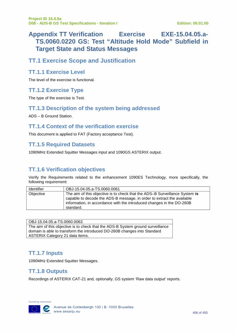
Project ID 15.4.5a D08 - ADS-B GS Test Specifications - Iteration I Edition: 00.01.00
406 of 455
Appendix TT Verification Exercise EXE-15.04.05.a-TS.0060.0220 GS: Test “Altitude Hold Mode” Subfield in Target State and Status Messages
TT.1 Exercise Scope and Justification
TT.1.1 Exercise Level The level of the exercise is functional.
TT.1.2 Exercise Type The type of the exercise is Test.
TT.1.3 Description of the system being addressed ADS – B Ground Station.
TT.1.4 Context of the verification exercise This document is applied to FAT (Factory acceptance Test).
TT.1.5 Required Datasets 1090MHz Extended Squitter Messages input and 1090GS ASTERIX output.
TT.1.6 Verification objectives Verify the Requirements related to the enhancement 1090ES Technology, more specifically, the following requirement:
Identifier OBJ-15.04.05.a-TS.0060.0061 Objective The aim of this objective is to check that the ADS–B Surveillance System is
capable to decode the ADS-B message, in order to extract the available information, in accordance with the introduced changes in the DO-260B standard.
OBJ-15.04.05.a-TS.0060.0063 The aim of this objective is to check that the ADS-B System ground surveillance domain is able to transform the introduced DO-260B changes into Standard ASTERIX Category 21 data items.
TT.1.7 Inputs 1090MHz Extended Squitter Messages.
TT.1.8 Outputs Recordings of ASTERIX CAT-21 and, optionally, GS system ‘Raw data output’ reports.
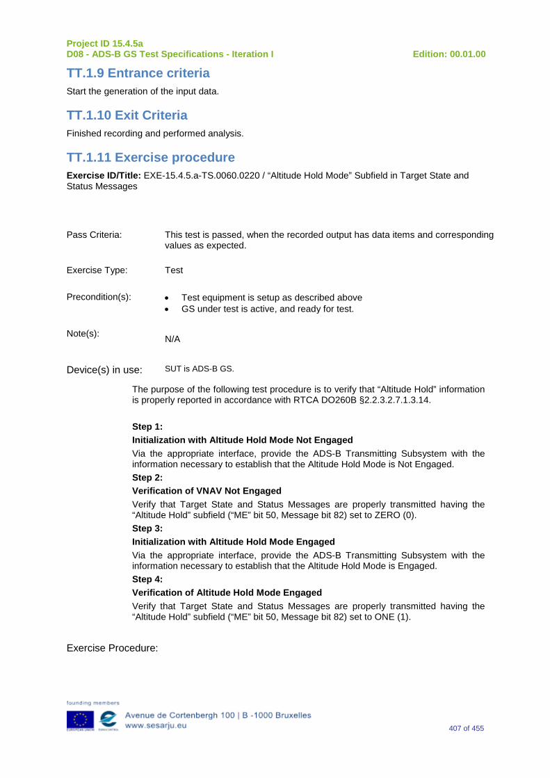
Project ID 15.4.5a D08 - ADS-B GS Test Specifications - Iteration I Edition: 00.01.00
407 of 455
TT.1.9 Entrance criteria Start the generation of the input data.
TT.1.10 Exit Criteria Finished recording and performed analysis.
TT.1.11 Exercise procedure Exercise ID/Title: EXE-15.4.5.a-TS.0060.0220 / “Altitude Hold Mode” Subfield in Target State and Status Messages
Pass Criteria: This test is passed, when the recorded output has data items and corresponding values as expected.
Exercise Type: Test
Precondition(s): • Test equipment is setup as described above • GS under test is active, and ready for test.
Note(s): N/A
Device(s) in use: SUT is ADS-B GS.
The purpose of the following test procedure is to verify that “Altitude Hold” information is properly reported in accordance with RTCA DO260B §2.2.3.2.7.1.3.14. Step 1: Initialization with Altitude Hold Mode Not Engaged Via the appropriate interface, provide the ADS-B Transmitting Subsystem with the information necessary to establish that the Altitude Hold Mode is Not Engaged. Step 2: Verification of VNAV Not Engaged Verify that Target State and Status Messages are properly transmitted having the “Altitude Hold” subfield (“ME” bit 50, Message bit 82) set to ZERO (0). Step 3: Initialization with Altitude Hold Mode Engaged Via the appropriate interface, provide the ADS-B Transmitting Subsystem with the information necessary to establish that the Altitude Hold Mode is Engaged. Step 4: Verification of Altitude Hold Mode Engaged Verify that Target State and Status Messages are properly transmitted having the “Altitude Hold” subfield (“ME” bit 50, Message bit 82) set to ONE (1).
Exercise Procedure:

Project ID 15.4.5a D08 - ADS-B GS Test Specifications - Iteration I Edition: 00.01.00
408 of 455
Step Action Expected Reaction Pass/Fail Comment
1 Put the GS system under test into the related test configuration.
2 Prepare the test reporting capture tools to capture related GS system ASTERIX CAT-21 and, optional, GS system ‘Raw Data Output’ reports.
3 Prepare the test message source to play the test scenario.
4 Play the test scenario.
5 When the test scenario is complete, stop the recording of ASTERIX CAT-21 and, optional, GS system ‘Raw data output’ reports.
6 Analyze the recorded data:
7 Input test scenario versus ASTERIX CAT-21 reports and
8 Optional, Input test scenario versus GS system ‘Raw data output reports
9 Verify that the GS system under test has generated the expected outputs, and has fulfilled the test objective.
Exercise result:
Pass Fail Done By (Name, Organisation)
Configuration(s) during the exercise Date
Table 71: Verification Exercise Result

Project ID 15.4.5a D08 - ADS-B GS Test Specifications - Iteration I Edition: 00.01.00
409 of 455
TT.1.12 Verification SUT requirements N/A
TT.1.13 Exercise Tool, Verification Technique and/or Platform
ADS-BGround Station
Power
ASTERIX(and Raw Data)
Recording
UTC Time Reference
RF Source(Message Generator)
The Exercise will be verified in a platform with the following foreseen tools/equipment:
-Ground Station ADS–B
-Message Generator
-ASTERIX (and Raw Data) Recording Tool
-Power Source
-UTC time Reference
The Item reported above will be capable to perform the functionalities reported below.
Ground Station ADS-B
The primary function of the 1090 GS is to receive 1090 MHz Mode S Extended Squitter messages, extract the data contained therein, and create appropriated ASTERIX Category 21 and 23 Reports (and optionally, Raw Data).
Message Generator
The Messages Generator will be capable to generate the data coming from the Remote System (ADS–B Ground Station or 1090 Receiver) like:
•Target data stream with inside the information extracted by the ADS–B message (ASTERIX CAT 21 in the case of Ground Station or Raw Data in the case that remote system is a 1090 MHz Receiver).
•Operational Data Stream with inside the Remote System’s Operational Status Information (ASTERIX CAT 23 in the case of Ground Station or Raw Data in the case that remote system is a 1090 MHz Receiver).
UTC Time Reference
The UTC Time reference is the solution adopted in the Test Scenario in order to provide the Synchronization in the Ground Station by UTC Time.
ASTERIX Recording Equipment
The ASTERIX recording equipment will be capable to record all ASTERIX reports sent from the 1090 ES Ground Station.

Project ID 15.4.5a D08 - ADS-B GS Test Specifications - Iteration I Edition: 00.01.00
410 of 455
TT.1.14 Verification Platform needs See section 3.5 Verification Platform Needs.
TT.1.15 Platform Configuration N/A
TT.1.16 Configuration(s) Identification of the Verification Platform N/A
TT.1.17 Links to other Verification Exercises N/A
TT.1.18 Representatively level/ limitations N/A
TT.2 Exercises Planning and management
TT.2.1 Activities N/A
TT.2.1.1 Preparatory activities Setup the tools/equipment listed in 3.5 and TT.1.13 in order to meet the Test Preconditions.
TT.2.1.2 Execution activities Play the scenario generating in the input the desired messages and record the relevant ASTERIX (and Raw Data) output.
TT.2.1.3 Post execution activities The post execution activities will be mainly focused on the analysis of recorded ASTERIX reports (and Raw Data reports). The analysis shall be done in order to verify the right information propagation as requested in each Test Scenario.
TT.2.2 Human Resources N/A
TT.2.3 Responsibilities in the exercise N/A
TT.2.4 Training N/A
TT.2.5 Time planning N/A
Project ID 15.4.5a D08 - ADS-B GS Test Specifications - Iteration I Edition: 00.01.00
411 of 455
TT.2.6 Risks N/A
TT.2.7 Errors and Observation handling N/A
TT.3 Analysis Specification
TT.3.1 Data collection methods The data collection during the test will be Qualitative. In fact after test execution the analysis of ASTERIX Data will be performed verifying that the values reported in the output are in line with the values generated in the input.
TT.3.2 Analysis method N/A
TT.3.3 Data logging requirements The data logging requirements for this scenario will foresee at least ASTERIX CAT 21 items.
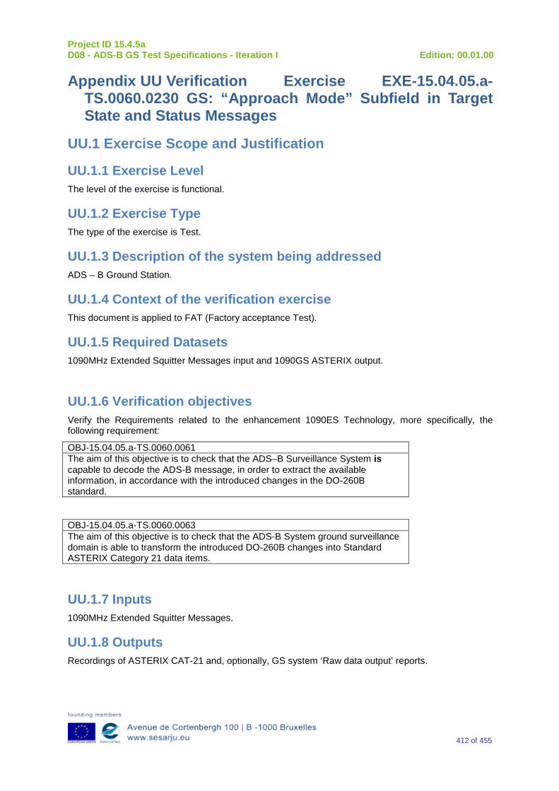
Project ID 15.4.5a D08 - ADS-B GS Test Specifications - Iteration I Edition: 00.01.00
412 of 455
Appendix UU Verification Exercise EXE-15.04.05.a-TS.0060.0230 GS: “Approach Mode” Subfield in Target State and Status Messages
UU.1 Exercise Scope and Justification
UU.1.1 Exercise Level The level of the exercise is functional.
UU.1.2 Exercise Type The type of the exercise is Test.
UU.1.3 Description of the system being addressed ADS – B Ground Station.
UU.1.4 Context of the verification exercise This document is applied to FAT (Factory acceptance Test).
UU.1.5 Required Datasets 1090MHz Extended Squitter Messages input and 1090GS ASTERIX output.
UU.1.6 Verification objectives Verify the Requirements related to the enhancement 1090ES Technology, more specifically, the following requirement:
OBJ-15.04.05.a-TS.0060.0061 The aim of this objective is to check that the ADS–B Surveillance System is capable to decode the ADS-B message, in order to extract the available information, in accordance with the introduced changes in the DO-260B standard.
OBJ-15.04.05.a-TS.0060.0063 The aim of this objective is to check that the ADS-B System ground surveillance domain is able to transform the introduced DO-260B changes into Standard ASTERIX Category 21 data items.
UU.1.7 Inputs 1090MHz Extended Squitter Messages.
UU.1.8 Outputs Recordings of ASTERIX CAT-21 and, optionally, GS system ‘Raw data output’ reports.
Project ID 15.4.5a D08 - ADS-B GS Test Specifications - Iteration I Edition: 00.01.00
413 of 455
UU.1.9 Entrance criteria Start the generation of the input data.
UU.1.10 Exit Criteria Finished recording and performed analysis.
UU.1.11 Exercise procedure Exercise ID/Title: EXE-15.4.5.a-TS.0060.0230 / “Approach Mode” Subfield in Target State and Status Messages
Pass Criteria: This test is passed, when the recorded output has data items and corresponding values as expected.
Exercise Type: Test
Precondition(s): • Test equipment is setup as described above • GS under test is active, and ready for test.
Note(s): N/A
Device(s) in use: SUT is ADS-B GS.
The purpose of the following test procedure is to verify that “Approach Mode” information is properly reported in accordance with RTCA DO260B §2.2.3.2.7.1.3.16. Step 1: Initialization with Approach Mode Not Engaged Via the appropriate interface, provide the ADS-B Transmitting Subsystem with the information necessary to establish that the Approach Mode is Not Engaged. Step 2: Verification of Approach Mode Not Engaged Verify that Target State and Status Messages are properly transmitted having the “Approach Mode” subfield (“ME” bit 52, Message bit 84) set to ZERO (0). Step 3: Initialization with Approach Mode Engaged Via the appropriate interface, provide the ADS-B Transmitting Subsystem with the information necessary to establish that the Approach Mode is Engaged. Step 4: Verification of Approach Mode Engaged Verify that Target State and Status Messages are properly transmitted having the “Approach Mode” subfield (“ME” bit 52, Message bit 84) set to ONE (1).
Exercise Procedure:
Project ID 15.4.5a D08 - ADS-B GS Test Specifications - Iteration I Edition: 00.01.00
414 of 455
Step Action Expected Reaction Pass/Fail Comment
1 Put the GS system under test into the related test configuration.
2 Prepare the test reporting capture tools to capture related GS system ASTERIX CAT-21 and, optional, GS system ‘Raw Data Output’ reports.
3 Prepare the test message source to play the test scenario.
4 Play the test scenario.
5 When the test scenario is complete, stop the recording of ASTERIX CAT-21 and, optional, GS system ‘Raw data output’ reports.
6 Analyze the recorded data:
7 Input test scenario versus ASTERIX CAT-21 reports and
8 Optional, Input test scenario versus GS system ‘Raw data output reports
9 Verify that the GS system under test has generated the expected outputs, and has fulfilled the test objective.
Exercise result:
Pass Fail Done By (Name, Organisation)
Configuration(s) during the exercise Date
Table 72: Verification Exercise Result
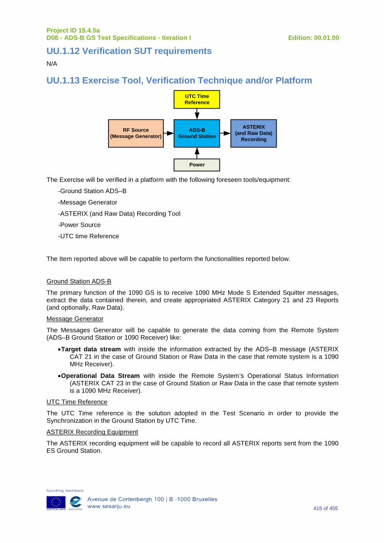
Project ID 15.4.5a D08 - ADS-B GS Test Specifications - Iteration I Edition: 00.01.00
415 of 455
UU.1.12 Verification SUT requirements N/A
UU.1.13 Exercise Tool, Verification Technique and/or Platform
ADS-BGround Station
Power
ASTERIX(and Raw Data)
Recording
UTC Time Reference
RF Source(Message Generator)
The Exercise will be verified in a platform with the following foreseen tools/equipment:
-Ground Station ADS–B
-Message Generator
-ASTERIX (and Raw Data) Recording Tool
-Power Source
-UTC time Reference
The Item reported above will be capable to perform the functionalities reported below.
Ground Station ADS-B
The primary function of the 1090 GS is to receive 1090 MHz Mode S Extended Squitter messages, extract the data contained therein, and create appropriated ASTERIX Category 21 and 23 Reports (and optionally, Raw Data).
Message Generator
The Messages Generator will be capable to generate the data coming from the Remote System (ADS–B Ground Station or 1090 Receiver) like:
•Target data stream with inside the information extracted by the ADS–B message (ASTERIX CAT 21 in the case of Ground Station or Raw Data in the case that remote system is a 1090 MHz Receiver).
•Operational Data Stream with inside the Remote System’s Operational Status Information (ASTERIX CAT 23 in the case of Ground Station or Raw Data in the case that remote system is a 1090 MHz Receiver).
UTC Time Reference
The UTC Time reference is the solution adopted in the Test Scenario in order to provide the Synchronization in the Ground Station by UTC Time.
ASTERIX Recording Equipment
The ASTERIX recording equipment will be capable to record all ASTERIX reports sent from the 1090 ES Ground Station.

Project ID 15.4.5a D08 - ADS-B GS Test Specifications - Iteration I Edition: 00.01.00
416 of 455
UU.1.14 Verification Platform needs See section 3.5 Verification Platform Needs.
UU.1.15 Platform Configuration N/A
UU.1.16 Configuration(s) Identification of the Verification Platform N/A
UU.1.17 Links to other Verification Exercises N/A
UU.1.18 Representatively level/ limitations N/A
UU.2 Exercises Planning and management
UU.2.1 Activities N/A
UU.2.1.1 Preparatory activities Setup the tools/equipment listed in 3.5 and UU.1.13 in order to meet the Test Preconditions.
UU.2.1.2 Execution activities Play the scenario generating in the input the desired messages and record the relevant ASTERIX (and Raw Data) output.
UU.2.1.3 Post execution activities The post execution activities will be mainly focused on the analysis of recorded ASTERIX reports (and Raw Data reports). The analysis shall be done in order to verify the right information propagation as requested in each Test Scenario.
UU.2.2 Human Resources N/A
UU.2.3 Responsibilities in the exercise N/A
UU.2.4 Training N/A
UU.2.5 Time planning N/A
Project ID 15.4.5a D08 - ADS-B GS Test Specifications - Iteration I Edition: 00.01.00
417 of 455
UU.2.6 Risks N/A
UU.2.7 Errors and Observation handling N/A
UU.3 Analysis Specification
UU.3.1 Data collection methods The data collection during the test will be Qualitative. In fact after test execution the analysis of ASTERIX Data will be performed verifying that the values reported in the output are in line with the values generated in the input.
UU.3.2 Analysis method N/A
UU.3.3 Data logging requirements The data logging requirements for this scenario will foresee at least ASTERIX CAT 21 items.

Project ID 15.4.5a D08 - ADS-B GS Test Specifications - Iteration I Edition: 00.01.00
418 of 455
Appendix VV Verification Exercise EXE-15.04.05.a-TS.0060.0240 GS: “LNAV Mode Engaged” Subfield in Target State and Status Messages
VV.1 Exercise Scope and Justification
VV.1.1 Exercise Level The level of the exercise is functional.
VV.1.2 Exercise Type The type of the exercise is Test.
VV.1.3 Description of the system being addressed ADS – B Ground Station.
VV.1.4 Context of the verification exercise This document is applied to FAT (Factory acceptance Test).
VV.1.5 Required Datasets 1090MHz Extended Squitter Messages input and 1090GS ASTERIX output.
VV.1.6 Verification objectives Verify the Requirements related to the enhancement 1090ES Technology, more specifically, the following requirement:
OBJ-15.04.05.a-TS.0060.0061 The aim of this objective is to check that the ADS–B Surveillance System is capable to decode the ADS-B message, in order to extract the available information, in accordance with the introduced changes in the DO-260B standard.
OBJ-15.04.05.a-TS.0060.0063 The aim of this objective is to check that the ADS-B System ground surveillance domain is able to transform the introduced DO-260B changes into Standard ASTERIX Category 21 data items.
VV.1.7 Inputs 1090MHz Extended Squitter Messages.
VV.1.8 Outputs Recordings of ASTERIX CAT-21 and, optionally, GS system ‘Raw data output’ reports.
Project ID 15.4.5a D08 - ADS-B GS Test Specifications - Iteration I Edition: 00.01.00
419 of 455
VV.1.9 Entrance criteria Start the generation of the input data.
VV.1.10 Exit Criteria Finished recording and performed analysis.
VV.1.11 Exercise procedure Exercise ID/Title: EXE-15.4.5.a-TS.0060.0240 / “LNAV Mode Engaged” Subfield in Target State and Status Messages
Pass Criteria: This test is passed, when the recorded output has data items and corresponding values as expected.
Exercise Type: Test
Precondition(s): • Test equipment is setup as described above • GS under test is active, and ready for test.
Note(s): N/A
Device(s) in use: SUT is ADS-B GS.
The purpose of the following test procedure is to verify that “LNAV Mode Engaged” information is properly reported in accordance with RTCA DO260B §2.2.3.2.7.1.3.18. Step 1: Initialization with LNAV Mode Not Engaged Via the appropriate interface, provide the ADS-B Transmitting Subsystem with the information necessary to establish that the LNAV Mode is Not Engaged. Step 2: Verification of LNAV Mode Not Engaged Verify that Target State and Status Messages are properly transmitted having the “LNAV Mode Engaged” subfield (“ME” bit 54, Message bit 86) set to ZERO (0). Step 3: Initialization with LNAV Mode Engaged Via the appropriate interface, provide the ADS-B Transmitting Subsystem with the information necessary to establish that the LNAV Mode is Engaged. Step 4: Verification of LNAV Mode Engaged Verify that Target State and Status Messages are properly transmitted having the “LNAV Mode Engaged” subfield (“ME” bit 54, Message bit 86) set to ONE (1).
Exercise Procedure:

Project ID 15.4.5a D08 - ADS-B GS Test Specifications - Iteration I Edition: 00.01.00
420 of 455
Step Action Expected Reaction Pass/Fail Comment
1 Put the GS system under test into the related test configuration.
2 Prepare the test reporting capture tools to capture related GS system ASTERIX CAT-21 and, optional, GS system ‘Raw Data Output’ reports.
3 Prepare the test message source to play the test scenario.
4 Play the test scenario.
5 When the test scenario is complete, stop the recording of ASTERIX CAT-21 and, optional, GS system ‘Raw data output’ reports.
6 Analyze the recorded data:
7 Input test scenario versus ASTERIX CAT-21 reports and
8 Optional, Input test scenario versus GS system ‘Raw data output reports
9 Verify that the GS system under test has generated the expected outputs, and has fulfilled the test objective.
Exercise result:
Pass Fail Done By (Name, Organisation)
Configuration(s) during the exercise Date
Table 73: Verification Exercise Result

Project ID 15.4.5a D08 - ADS-B GS Test Specifications - Iteration I Edition: 00.01.00
421 of 455
VV.1.12 Verification SUT requirements N/A
VV.1.13 Exercise Tool, Verification Technique and/or Platform
ADS-BGround Station
Power
ASTERIX(and Raw Data)
Recording
UTC Time Reference
RF Source(Message Generator)
The Exercise will be verified in a platform with the following foreseen tools/equipment:
-Ground Station ADS–B
-Message Generator
-ASTERIX (and Raw Data) Recording Tool
-Power Source
-UTC time Reference
The Item reported above will be capable to perform the functionalities reported below.
Ground Station ADS-B
The primary function of the 1090 GS is to receive 1090 MHz Mode S Extended Squitter messages, extract the data contained therein, and create appropriated ASTERIX Category 21 and 23 Reports (and optionally, Raw Data).
Message Generator
The Messages Generator will be capable to generate the data coming from the Remote System (ADS–B Ground Station or 1090 Receiver) like:
•Target data stream with inside the information extracted by the ADS–B message (ASTERIX CAT 21 in the case of Ground Station or Raw Data in the case that remote system is a 1090 MHz Receiver).
•Operational Data Stream with inside the Remote System’s Operational Status Information (ASTERIX CAT 23 in the case of Ground Station or Raw Data in the case that remote system is a 1090 MHz Receiver).
UTC Time Reference
The UTC Time reference is the solution adopted in the Test Scenario in order to provide the Synchronization in the Ground Station by UTC Time.
ASTERIX Recording Equipment
The ASTERIX recording equipment will be capable to record all ASTERIX reports sent from the 1090 ES Ground Station.
Project ID 15.4.5a D08 - ADS-B GS Test Specifications - Iteration I Edition: 00.01.00
422 of 455
VV.1.14 Verification Platform needs See section 3.5 Verification Platform Needs.
VV.1.15 Platform Configuration N/A
VV.1.16 Configuration(s) Identification of the Verification Platform N/A
VV.1.17 Links to other Verification Exercises N/A
VV.1.18 Representatively level/ limitations N/A
VV.2 Exercises Planning and management
VV.2.1 Activities N/A
VV.2.1.1 Preparatory activities Setup the tools/equipment listed in 3.5 and VV.1.13 in order to meet the Test Preconditions.
VV.2.1.2 Execution activities Play the scenario generating in the input the desired messages and record the relevant ASTERIX (and Raw Data) output.
VV.2.1.3 Post execution activities The post execution activities will be mainly focused on the analysis of recorded ASTERIX reports (and Raw Data reports). The analysis shall be done in order to verify the right information propagation as requested in each Test Scenario.
VV.2.2 Human Resources N/A
VV.2.3 Responsibilities in the exercise N/A
VV.2.4 Training N/A
VV.2.5 Time planning N/A

Project ID 15.4.5a D08 - ADS-B GS Test Specifications - Iteration I Edition: 00.01.00
423 of 455
VV.2.6 Risks N/A
VV.2.7 Errors and Observation handling N/A
VV.3 Analysis Specification
VV.3.1 Data collection methods The data collection during the test will be Qualitative. In fact after the test execution the analysis of ASTERIX Data will be performed verifying that the values reported in the output are in line with the values generated in the input.
VV.3.2 Analysis method N/A
VV.3.3 Data logging requirements The data logging requirements for this scenario will foresee at least ASTERIX CAT 21 items.
Project ID 15.4.5a D08 - ADS-B GS Test Specifications - Iteration I Edition: 00.01.00
424 of 455
Appendix WW Verification Exercise EXE-15.04.05.a-TS.0060.0250 GS: “Mode A (4096) Code” Subfield in Aircraft Status Messages
WW.1 Exercise Scope and Justification
WW.1.1 Exercise Level The level of the exercise is functional.
WW.1.2 Exercise Type The type of the exercise is Test.
WW.1.3 Description of the system being addressed ADS – B Ground Station.
WW.1.4 Context of the verification exercise This document is applied to FAT (Factory acceptance Test).
WW.1.5 Required Datasets 1090MHz Extended Squitter Messages input and 1090GS ASTERIX output.
WW.1.6 Verification objectives Verify the Requirements related to the enhancement 1090ES Technology, more specifically, the following requirement:
OBJ-15.04.05.a-TS.0060.0061 The aim of this objective is to check that the ADS–B Surveillance System is capable to decode the ADS-B message, in order to extract the available information, in accordance with the introduced changes in the DO-260B standard.
OBJ-15.04.05.a-TS.0060.0063 The aim of this objective is to check that the ADS-B System ground surveillance domain is able to transform the introduced DO-260B changes into Standard ASTERIX Category 21 data items.
WW.1.7 Inputs 1090MHz Extended Squitter Messages.
WW.1.8 Outputs Recordings of ASTERIX CAT-21 and, optionally, GS system ‘Raw data output’ reports.
Project ID 15.4.5a D08 - ADS-B GS Test Specifications - Iteration I Edition: 00.01.00
425 of 455
WW.1.9 Entrance criteria Start the generation of the input data.
WW.1.10 Exit Criteria Finished recording and performed analysis.
WW.1.11 Exercise procedure Exercise ID/Title: EXE-15.4.5.a-TS.0060.0250 / “Mode A (4096) Code” Subfield in Aircraft Status Messages
Pass Criteria: This test is passed, when the recorded output has data items and corresponding values as expected.
Exercise Type: Test
Precondition(s): • Test equipment is setup as described above • GS under test is active, and ready for test.
Note(s): N/A
Device(s) in use: SUT is ADS-B GS.
The ADS-B Transmitting Subsystem will broadcast the Mode A (4096) Code setting in the Extended Squitter Aircraft Status Message (TYPE=28, Subtype=1). Step 1: Configure the ADS-B Transmitting Subsystem to transmit Airborne Position Messages. Set the ADS-B Transmitting Subsystem to Airborne status. Produce valid Airborne Position Messages at the nominal rate with valid position and altitude data. Verify that the ADS-B Transmitting Subsystem begins to transmit Extended Squitter Aircraft Status Messages at the nominal rate with the TYPE Subfield set to 28 (binary 1 1100) and the Subtype Subfield set to ONE (binary 001). Verify that the Mode A Code being broadcast is the one set by the pilot.
Exercise Procedure:
Step Action Expected Reaction Pass/Fail Comment
1 Put the GS system under test into the related test configuration.
2 Prepare the test reporting capture tools to capture related GS system ASTERIX CAT-21 and, optional, GS system ‘Raw Data Output’ reports.
Project ID 15.4.5a D08 - ADS-B GS Test Specifications - Iteration I Edition: 00.01.00
426 of 455
3 Prepare the test message source to play the test scenario.
4 Play the test scenario.
5 When the test scenario is complete, stop the recording of ASTERIX CAT-21 and, optional, GS system ‘Raw data output’ reports.
6 Analyze the recorded data:
7 Input test scenario versus ASTERIX CAT-21 reports and
8 Optional, Input test scenario versus GS system ‘Raw data output reports
9 Verify that the GS system under test has generated the expected outputs, and has fulfilled the test objective.
Exercise result:
Pass Fail Done By (Name, Organisation)
Configuration(s) during the exercise Date
Table 74: Verification Exercise Result
WW.1.12 Verification SUT requirements N/A
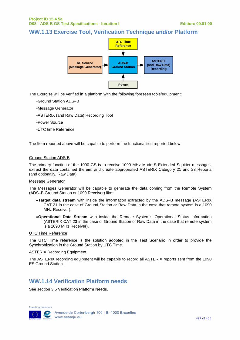
Project ID 15.4.5a D08 - ADS-B GS Test Specifications - Iteration I Edition: 00.01.00
427 of 455
WW.1.13 Exercise Tool, Verification Technique and/or Platform
ADS-BGround Station
Power
ASTERIX(and Raw Data)
Recording
UTC Time Reference
RF Source(Message Generator)
The Exercise will be verified in a platform with the following foreseen tools/equipment:
-Ground Station ADS–B
-Message Generator
-ASTERIX (and Raw Data) Recording Tool
-Power Source
-UTC time Reference
The Item reported above will be capable to perform the functionalities reported below.
Ground Station ADS-B
The primary function of the 1090 GS is to receive 1090 MHz Mode S Extended Squitter messages, extract the data contained therein, and create appropriated ASTERIX Category 21 and 23 Reports (and optionally, Raw Data).
Message Generator
The Messages Generator will be capable to generate the data coming from the Remote System (ADS–B Ground Station or 1090 Receiver) like:
•Target data stream with inside the information extracted by the ADS–B message (ASTERIX CAT 21 in the case of Ground Station or Raw Data in the case that remote system is a 1090 MHz Receiver).
•Operational Data Stream with inside the Remote System’s Operational Status Information (ASTERIX CAT 23 in the case of Ground Station or Raw Data in the case that remote system is a 1090 MHz Receiver).
UTC Time Reference
The UTC Time reference is the solution adopted in the Test Scenario in order to provide the Synchronization in the Ground Station by UTC Time.
ASTERIX Recording Equipment
The ASTERIX recording equipment will be capable to record all ASTERIX reports sent from the 1090 ES Ground Station.
WW.1.14 Verification Platform needs See section 3.5 Verification Platform Needs.
Project ID 15.4.5a D08 - ADS-B GS Test Specifications - Iteration I Edition: 00.01.00
428 of 455
WW.1.15 Platform Configuration N/A
WW.1.16 Configuration(s) Identification of the Verification Platform N/A
WW.1.17 Links to other Verification Exercises N/A
WW.1.18 Representatively level/ limitations N/A
WW.2 Exercises Planning and management
WW.2.1 Activities N/A
WW.2.1.1 Preparatory activities Setup the tools/equipment listed in 3.5 and WW.1.13 in order to meet the Test Preconditions.
WW.2.1.2 Execution activities Play the scenario generating in the input the desired messages and record the relevant ASTERIX (and Raw Data) output.
WW.2.1.3 Post execution activities The post execution activities will be mainly focused on the analysis of recorded ASTERIX reports (and Raw Data reports). The analysis shall be done in order to verify the right information propagation as requested in each Test Scenario.
WW.2.2 Human Resources N/A
WW.2.3 Responsibilities in the exercise N/A
WW.2.4 Training N/A
WW.2.5 Time planning N/A
WW.2.6 Risks N/A
Project ID 15.4.5a D08 - ADS-B GS Test Specifications - Iteration I Edition: 00.01.00
429 of 455
WW.2.7 Errors and Observation handling N/A
WW.3 Analysis Specification
WW.3.1 Data collection methods The data collection during the test will be Qualitative. In fact after test execution the analysis of ASTERIX Data will be performed verifying that the values reported in the output are in line with the values generated in the input.
WW.3.2 Analysis method N/A
WW.3.3 Data logging requirements The data logging requirements for this scenario will foresee at least ASTERIX CAT 21 items.
Project ID 15.4.5a D08 - ADS-B GS Test Specifications - Iteration I Edition: 00.01.00
430 of 455
Appendix XX Verification Exercise EXE-15.04.05.a-TS.0060.0260 GS: “Movement” Subfield in ADS-B Surface Position Messages
XX.1 Exercise Scope and Justification
XX.1.1 Exercise Level The level of the exercise is functional.
XX.1.2 Exercise Type The type of the exercise is Test.
XX.1.3 Description of the system being addressed ADS – B Ground Station.
XX.1.4 Context of the verification exercise This document is applied to FAT (Factory acceptance Test).
XX.1.5 Required Datasets 1090MHz Extended Squitter Messages input and 1090GS ASTERIX output.
XX.1.6 Verification objectives Verify the Requirements related to the enhancement 1090ES Technology, more specifically, the following requirement:
OBJ-15.04.05.a-TS.0060.0061 The aim of this objective is to check that the ADS–B Surveillance System is capable to decode the ADS-B message, in order to extract the available information, in accordance with the introduced changes in the DO-260B standard.
OBJ-15.04.05.a-TS.0060.0063 The aim of this objective is to check that the ADS-B System ground surveillance domain is able to transform the introduced DO-260B changes into Standard ASTERIX Category 21 data items.
XX.1.7 Inputs 1090MHz Extended Squitter Messages.
XX.1.8 Outputs Recordings of ASTERIX CAT-21 and, optionally, GS system ‘Raw data output’ reports.
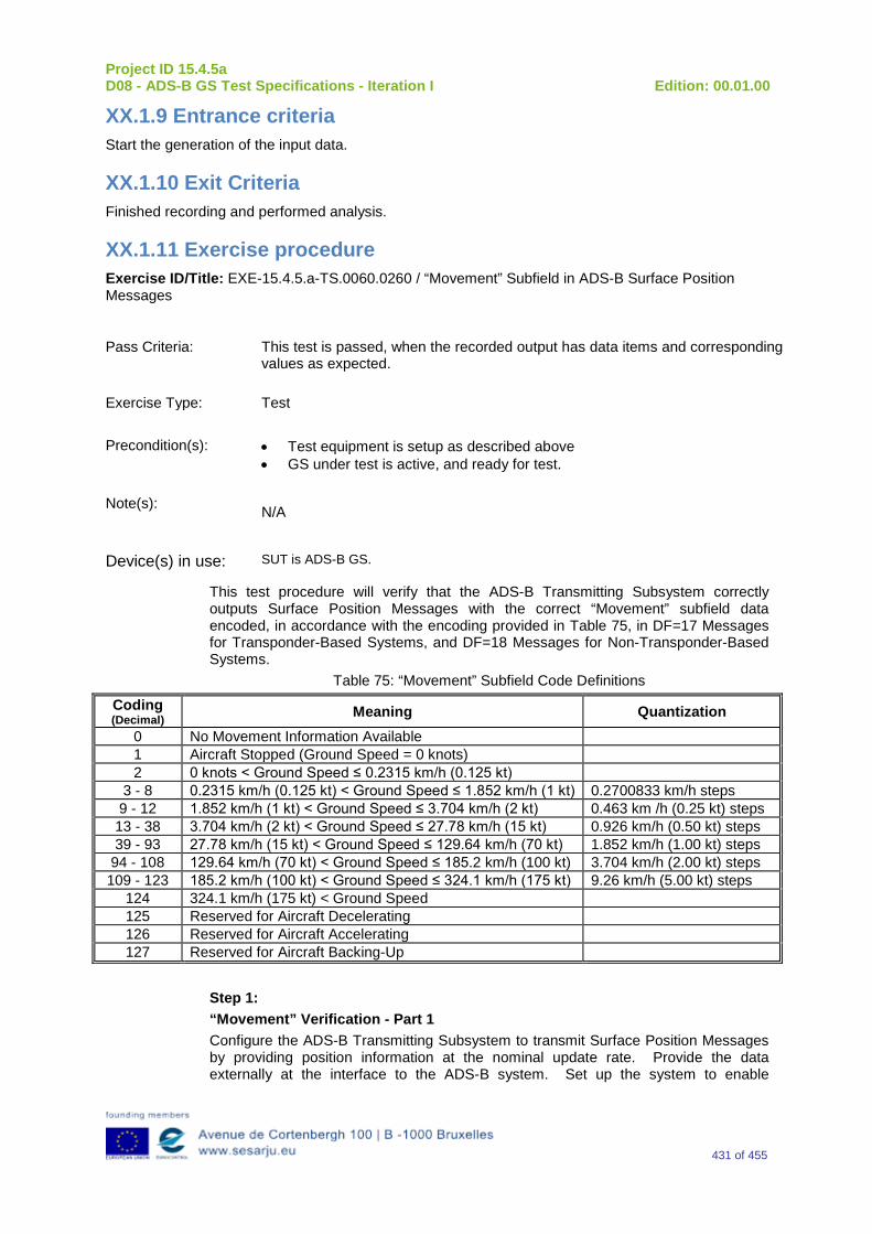
Project ID 15.4.5a D08 - ADS-B GS Test Specifications - Iteration I Edition: 00.01.00
431 of 455
XX.1.9 Entrance criteria Start the generation of the input data.
XX.1.10 Exit Criteria Finished recording and performed analysis.
XX.1.11 Exercise procedure Exercise ID/Title: EXE-15.4.5.a-TS.0060.0260 / “Movement” Subfield in ADS-B Surface Position Messages
Pass Criteria: This test is passed, when the recorded output has data items and corresponding values as expected.
Exercise Type: Test
Precondition(s): • Test equipment is setup as described above • GS under test is active, and ready for test.
Note(s): N/A
Device(s) in use: SUT is ADS-B GS.
This test procedure will verify that the ADS-B Transmitting Subsystem correctly outputs Surface Position Messages with the correct “Movement” subfield data encoded, in accordance with the encoding provided in Table 75, in DF=17 Messages for Transponder-Based Systems, and DF=18 Messages for Non-Transponder-Based Systems.
Table 75: “Movement” Subfield Code Definitions
Coding (Decimal) Meaning Quantization
0 No Movement Information Available 1 Aircraft Stopped (Ground Speed = 0 knots) 2 0 knots < Ground Speed ≤ 0.2315 km/h (0.125 kt)
3 - 8 0.2315 km/h (0.125 kt) < Ground Speed ≤ 1.852 km/h (1 kt) 0.2700833 km/h steps 9 - 12 1.852 km/h (1 kt) < Ground Speed ≤ 3.704 km/h (2 kt) 0.463 km /h (0.25 kt) steps 13 - 38 3.704 km/h (2 kt) < Ground Speed ≤ 27.78 km/h (15 kt) 0.926 km/h (0.50 kt) steps 39 - 93 27.78 km/h (15 kt) < Ground Speed ≤ 129.64 km/h (70 kt) 1.852 km/h (1.00 kt) steps
94 - 108 129.64 km/h (70 kt) < Ground Speed ≤ 185.2 km/h (100 kt) 3.704 km/h (2.00 kt) steps 109 - 123 185.2 km/h (100 kt) < Ground Speed ≤ 324.1 km/h (175 kt) 9.26 km/h (5.00 kt) steps
124 324.1 km/h (175 kt) < Ground Speed 125 Reserved for Aircraft Decelerating 126 Reserved for Aircraft Accelerating 127 Reserved for Aircraft Backing-Up
Step 1: “Movement” Verification - Part 1 Configure the ADS-B Transmitting Subsystem to transmit Surface Position Messages by providing position information at the nominal update rate. Provide the data externally at the interface to the ADS-B system. Set up the system to enable
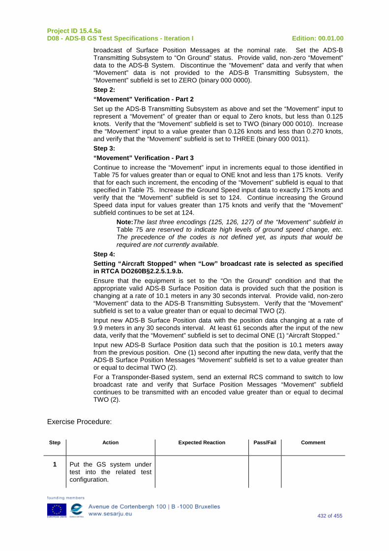
Project ID 15.4.5a D08 - ADS-B GS Test Specifications - Iteration I Edition: 00.01.00
432 of 455
broadcast of Surface Position Messages at the nominal rate. Set the ADS-B Transmitting Subsystem to “On Ground” status. Provide valid, non-zero “Movement” data to the ADS-B System. Discontinue the “Movement” data and verify that when “Movement” data is not provided to the ADS-B Transmitting Subsystem, the “Movement” subfield is set to ZERO (binary 000 0000). Step 2: “Movement” Verification - Part 2 Set up the ADS-B Transmitting Subsystem as above and set the “Movement” input to represent a “Movement” of greater than or equal to Zero knots, but less than 0.125 knots. Verify that the “Movement” subfield is set to TWO (binary 000 0010). Increase the “Movement” input to a value greater than 0.126 knots and less than 0.270 knots, and verify that the “Movement” subfield is set to THREE (binary 000 0011). Step 3: “Movement” Verification - Part 3 Continue to increase the “Movement” input in increments equal to those identified in Table 75 for values greater than or equal to ONE knot and less than 175 knots. Verify that for each such increment, the encoding of the “Movement” subfield is equal to that specified in Table 75. Increase the Ground Speed input data to exactly 175 knots and verify that the “Movement” subfield is set to 124. Continue increasing the Ground Speed data input for values greater than 175 knots and verify that the “Movement” subfield continues to be set at 124.
Note:The last three encodings (125, 126, 127) of the “Movement” subfield in Table 75 are reserved to indicate high levels of ground speed change, etc. The precedence of the codes is not defined yet, as inputs that would be required are not currently available.
Step 4: Setting “Aircraft Stopped” when “Low” broadcast rate is selected as specified in RTCA DO260B§2.2.5.1.9.b. Ensure that the equipment is set to the “On the Ground” condition and that the appropriate valid ADS-B Surface Position data is provided such that the position is changing at a rate of 10.1 meters in any 30 seconds interval. Provide valid, non-zero “Movement” data to the ADS-B Transmitting Subsystem. Verify that the “Movement” subfield is set to a value greater than or equal to decimal TWO (2). Input new ADS-B Surface Position data with the position data changing at a rate of 9.9 meters in any 30 seconds interval. At least 61 seconds after the input of the new data, verify that the “Movement” subfield is set to decimal ONE (1) “Aircraft Stopped.” Input new ADS-B Surface Position data such that the position is 10.1 meters away from the previous position. One (1) second after inputting the new data, verify that the ADS-B Surface Position Messages “Movement” subfield is set to a value greater than or equal to decimal TWO (2). For a Transponder-Based system, send an external RCS command to switch to low broadcast rate and verify that Surface Position Messages “Movement” subfield continues to be transmitted with an encoded value greater than or equal to decimal TWO (2).
Exercise Procedure:
Step Action Expected Reaction Pass/Fail Comment
1 Put the GS system under test into the related test configuration.
Project ID 15.4.5a D08 - ADS-B GS Test Specifications - Iteration I Edition: 00.01.00
433 of 455
2 Prepare the test reporting capture tools to capture related GS system ASTERIX CAT-21 and, optional, GS system ‘Raw Data Output’ reports.
3 Prepare the test message source to play the test scenario.
4 Play the test scenario.
5 When the test scenario is complete, stop the recording of ASTERIX CAT-21 and, optional, GS system ‘Raw data output’ reports.
6 Analyze the recorded data:
7 Input test scenario versus ASTERIX CAT-21 reports and
8 Optional, Input test scenario versus GS system ‘Raw data output reports
9 Verify that the GS system under test has generated the expected outputs, and has fulfilled the test objective.
Exercise result:
Pass Fail Done By (Name, Organisation)
Configuration(s) during the exercise Date
Table 76: Verification Exercise Result
XX.1.12 Verification SUT requirements N/A

Project ID 15.4.5a D08 - ADS-B GS Test Specifications - Iteration I Edition: 00.01.00
434 of 455
XX.1.13 Exercise Tool, Verification Technique and/or Platform
ADS-BGround Station
Power
ASTERIX(and Raw Data)
Recording
UTC Time Reference
RF Source(Message Generator)
The Exercise will be verified in a platform with the following foreseen tools/equipment:
-Ground Station ADS–B
-Message Generator
-ASTERIX (and Raw Data) Recording Tool
-Power Source
-UTC time Reference
The Item reported above will be capable to perform the functionalities reported below.
Ground Station ADS-B
The primary function of the 1090 GS is to receive 1090 MHz Mode S Extended Squitter messages, extract the data contained therein, and create appropriated ASTERIX Category 21 and 23 Reports (and optionally, Raw Data).
Message Generator
The Messages Generator will be capable to generate the data coming from the Remote System (ADS–B Ground Station or 1090 Receiver) like:
•Target data stream with inside the information extracted by the ADS–B message (ASTERIX CAT 21 in the case of Ground Station or Raw Data in the case that remote system is a 1090 MHz Receiver).
•Operational Data Stream with inside the Remote System’s Operational Status Information (ASTERIX CAT 23 in the case of Ground Station or Raw Data in the case that remote system is a 1090 MHz Receiver).
UTC Time Reference
The UTC Time reference is the solution adopted in the Test Scenario in order to provide the Synchronization in the Ground Station by UTC Time.
ASTERIX Recording Equipment
The ASTERIX recording equipment will be capable to record all ASTERIX reports sent from the 1090 ES Ground Station.
XX.1.14 Verification Platform needs See section 3.5 Verification Platform Needs.
Project ID 15.4.5a D08 - ADS-B GS Test Specifications - Iteration I Edition: 00.01.00
435 of 455
XX.1.15 Platform Configuration N/A
XX.1.16 Configuration(s) Identification of the Verification Platform N/A
XX.1.17 Links to other Verification Exercises N/A
XX.1.18 Representatively level/ limitations N/A
XX.2 Exercises Planning and management
XX.2.1 Activities N/A
XX.2.1.1 Preparatory activities Setup the tools/equipment listed in 3.5 and XX.1.13 in order to meet the Test Preconditions.
XX.2.1.2 Execution activities Play the scenario generating in the input the desired messages and record the relevant ASTERIX (and Raw Data) output.
XX.2.1.3 Post execution activities The post execution activities will be mainly focused on the analysis of recorded ASTERIX reports (and Raw Data reports). The analysis shall be done in order to verify the right information propagation as requested in each Test Scenario.
XX.2.2 Human Resources N/A
XX.2.3 Responsibilities in the exercise N/A
XX.2.4 Training N/A
XX.2.5 Time planning N/A
XX.2.6 Risks N/A
Project ID 15.4.5a D08 - ADS-B GS Test Specifications - Iteration I Edition: 00.01.00
436 of 455
XX.2.7 Errors and Observation handling N/A
XX.3 Analysis Specification
XX.3.1 Data collection methods The data collection during the test will be Qualitative. In fact after test execution the analysis of ASTERIX Data will be performed verifying that the values reported in the output are in line with the values generated in the input.
XX.3.2 Analysis method N/A
XX.3.3 Data logging requirements The data logging requirements for this scenario will foresee at least ASTERIX CAT 21 items.
Project ID 15.4.5a D08 - ADS-B GS Test Specifications - Iteration I Edition: 00.01.00
437 of 455
Appendix YY Verification Exercise EXE-15.04.05.a-TS.0060.0270 GS: “SUBTYPE” Code Subfield in Surface System Status Messages
YY.1 Exercise Scope and Justification
YY.1.1 Exercise Level The level of the exercise is functional.
YY.1.2 Exercise Type The type of the exercise is Analysis.
YY.1.3 Description of the system being addressed ADS – B Ground Station.
YY.1.4 Context of the verification exercise This document is applied to FAT (Factory acceptance Test).
YY.1.5 Required Datasets 1090MHz Extended Squitter Messages input and 1090GS ASTERIX output.
YY.1.6 Verification objectives Verify the Requirements related to the enhancement 1090ES Technology, more specifically, the following requirement:
OBJ-15.04.05.a-TS.0060.0061 The aim of this objective is to check that the ADS–B Surveillance System is capable to decode the ADS-B message, in order to extract the available information, in accordance with the introduced changes in the DO-260B standard.
OBJ-15.04.05.a-TS.0060.0063 The aim of this objective is to check that the ADS-B System ground surveillance domain is able to transform the introduced DO-260B changes into Standard ASTERIX Category 21 data items.
YY.1.7 Inputs Design documentation.
YY.1.8 Outputs N/A
YY.1.9 Entrance criteria N/A
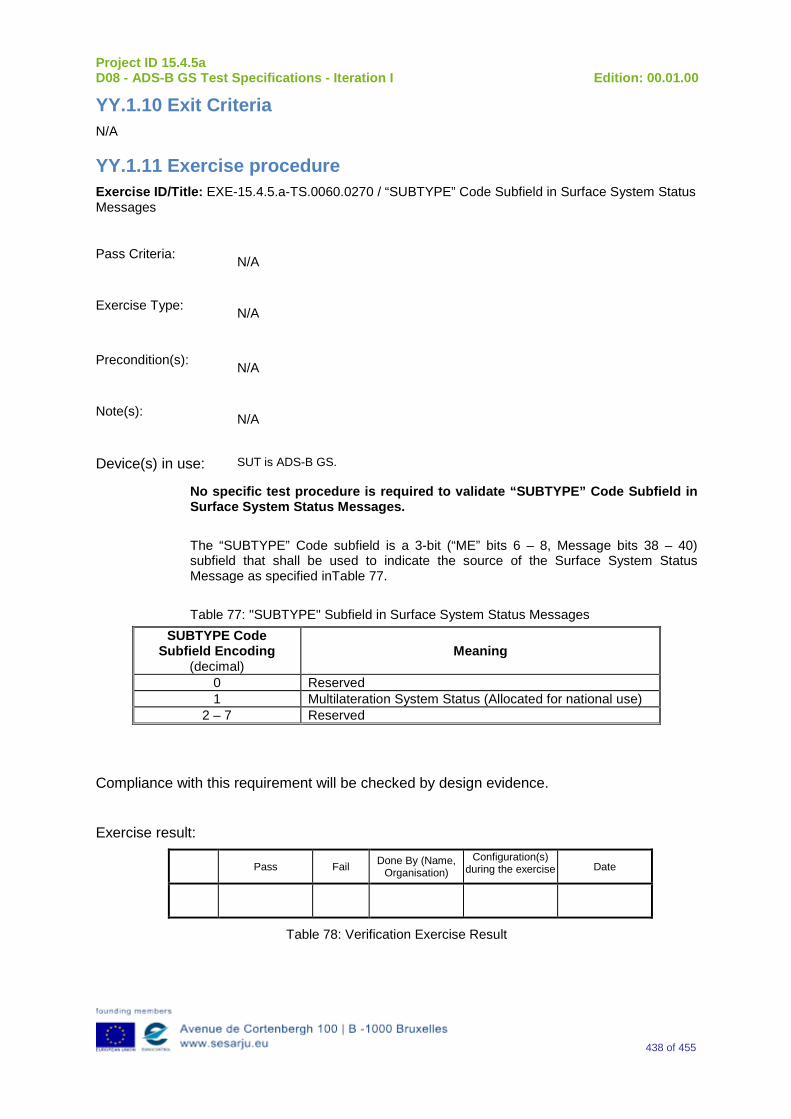
Project ID 15.4.5a D08 - ADS-B GS Test Specifications - Iteration I Edition: 00.01.00
438 of 455
YY.1.10 Exit Criteria N/A
YY.1.11 Exercise procedure Exercise ID/Title: EXE-15.4.5.a-TS.0060.0270 / “SUBTYPE” Code Subfield in Surface System Status Messages
Pass Criteria: N/A
Exercise Type: N/A
Precondition(s): N/A
Note(s): N/A
Device(s) in use: SUT is ADS-B GS.
No specific test procedure is required to validate “SUBTYPE” Code Subfield in Surface System Status Messages. The “SUBTYPE” Code subfield is a 3-bit (“ME” bits 6 – 8, Message bits 38 – 40) subfield that shall be used to indicate the source of the Surface System Status Message as specified inTable 77. Table 77: "SUBTYPE" Subfield in Surface System Status Messages
SUBTYPE Code Subfield Encoding
(decimal) Meaning
0 Reserved 1 Multilateration System Status (Allocated for national use)
2 – 7 Reserved
Compliance with this requirement will be checked by design evidence.
Exercise result:
Pass Fail Done By (Name, Organisation)
Configuration(s) during the exercise Date
Table 78: Verification Exercise Result
Project ID 15.4.5a D08 - ADS-B GS Test Specifications - Iteration I Edition: 00.01.00
439 of 455
YY.1.12 Verification SUT requirements N/A
YY.1.13 Exercise Tool, Verification Technique and/or Platform N/A
YY.1.14 Verification Platform needs N/A
YY.1.15 Platform Configuration N/A
YY.1.16 Configuration(s) Identification of the Verification Platform N/A
YY.1.17 Links to other Verification Exercises N/A
YY.1.18 Representatively level/ limitations N/A
YY.2 Exercises Planning and management
YY.2.1 Activities N/A
YY.2.1.1 Preparatory activities NA
YY.2.1.2 Execution activities N/A
YY.2.1.3 Post execution activities N/A
YY.2.2 Human Resources N/A
YY.2.3 Responsibilities in the exercise N/A
YY.2.4 Training N/A
Project ID 15.4.5a D08 - ADS-B GS Test Specifications - Iteration I Edition: 00.01.00
440 of 455
YY.2.5 Time planning N/A
YY.2.6 Risks N/A
YY.2.7 Errors and Observation handling N/A
YY.3 Analysis Specification
YY.3.1 Data collection methods N/A
YY.3.2 Analysis method In the 15.4.5b project the Analysis Method will be defined according to Internal Industry Procedures.
YY.3.3 Data logging requirements The data logging requirements for this scenario will foresee at least ASTERIX CAT 21 items.
Project ID 15.4.5a D08 - ADS-B GS Test Specifications - Iteration I Edition: 00.01.00
441 of 455
Appendix ZZ Verification Exercises EXE-15.04.05.a-TS.0060.0280 GS: “Reserved for ADS-R Flag” Subfield in Target State and Status Messages
ZZ.1 Exercise Scope and Justification
ZZ.1.1 Exercise Level The level of the exercise is functional.
ZZ.1.2 Exercise Type The type of the exercise is Test.
ZZ.1.3 Description of the system being addressed ADS – B Ground Station.
ZZ.1.4 Context of the verification exercise This document is applied to FAT (Factory acceptance Test).
ZZ.1.5 Required Datasets 1090MHz Extended Squitter Messages input and 1090GS ASTERIX output.
ZZ.1.6 Verification objectives Verify the Requirements related to the enhancement 1090ES Technology, more specifically, the following requirement:
OBJ-15.04.05.a-TS.0060.0061 The aim of this objective is to check that the ADS–B Surveillance System is capable to decode the ADS-B message, in order to extract the available information, in accordance with the introduced changes in the DO-260B standard.
OBJ-15.04.05.a-TS.0060.0063 The aim of this objective is to check that the ADS-B System ground surveillance domain is able to transform the introduced DO-260B changes into Standard ASTERIX Category 21 data items.
ZZ.1.7 Inputs 1090MHz Extended Squitter Messages.
ZZ.1.8 Outputs Recordings of ASTERIX CAT-21 and, optionally, GS system ‘Raw data output’ reports.
Project ID 15.4.5a D08 - ADS-B GS Test Specifications - Iteration I Edition: 00.01.00
442 of 455
ZZ.1.9 Entrance criteria Start the generation of the input data.
ZZ.1.10 Exit Criteria Finished recording and performed analysis.
ZZ.1.11 Exercise procedure Exercise ID/Title: EXE-15.4.5.a-TS.0060.0280 / “Reserved for ADS-R Flag” Subfield in Target State and Status Messages Pass Criteria: This test is passed, when the recorded output has data items and corresponding
values as expected.
Exercise Type: Test
Precondition(s): • Test equipment is setup as described above • GS under test is active, and ready for test.
Note(s): N/A
Device(s) in use: SUT is ADS-B GS.
ADS-B 1090ES Rebroadcast Messages are transmitted from a 1090ES ADS-B Ground Station as a rebroadcast of an ADS-B Message that was received by that Ground Station on an alternate ADS-B Data Link. The Airborne ADS-B Transmitting Subsystem will always transmit a ZERO (0) in “ME” bit 51 of the Target State and Status Message. These test procedures verify that “ME” bit 51 of the transmitted DF=17 Target State and Status Message from an Airborne ADS-B Transmitting Subsystem is always ZERO (0). Step 1: Target State and Status Message Initialization Via the appropriate interface, provide the ADS-B Transmitting Subsystem with valid Mode Control Panel Selected Altitude data in order to initialize transmission of Target State and Status Messages. Step 2: Verification of ADS-R Flag Set the ADS-B Transmitting Subsystem to Airborne status. Verify that Target State and Status Messages are broadcast with the “ME” bit 51 (Message bit 83) set to ZERO (0).
Exercise Procedure:
Step Action Expected Reaction Pass/Fail Comment
1 Put the GS system under test into the related test
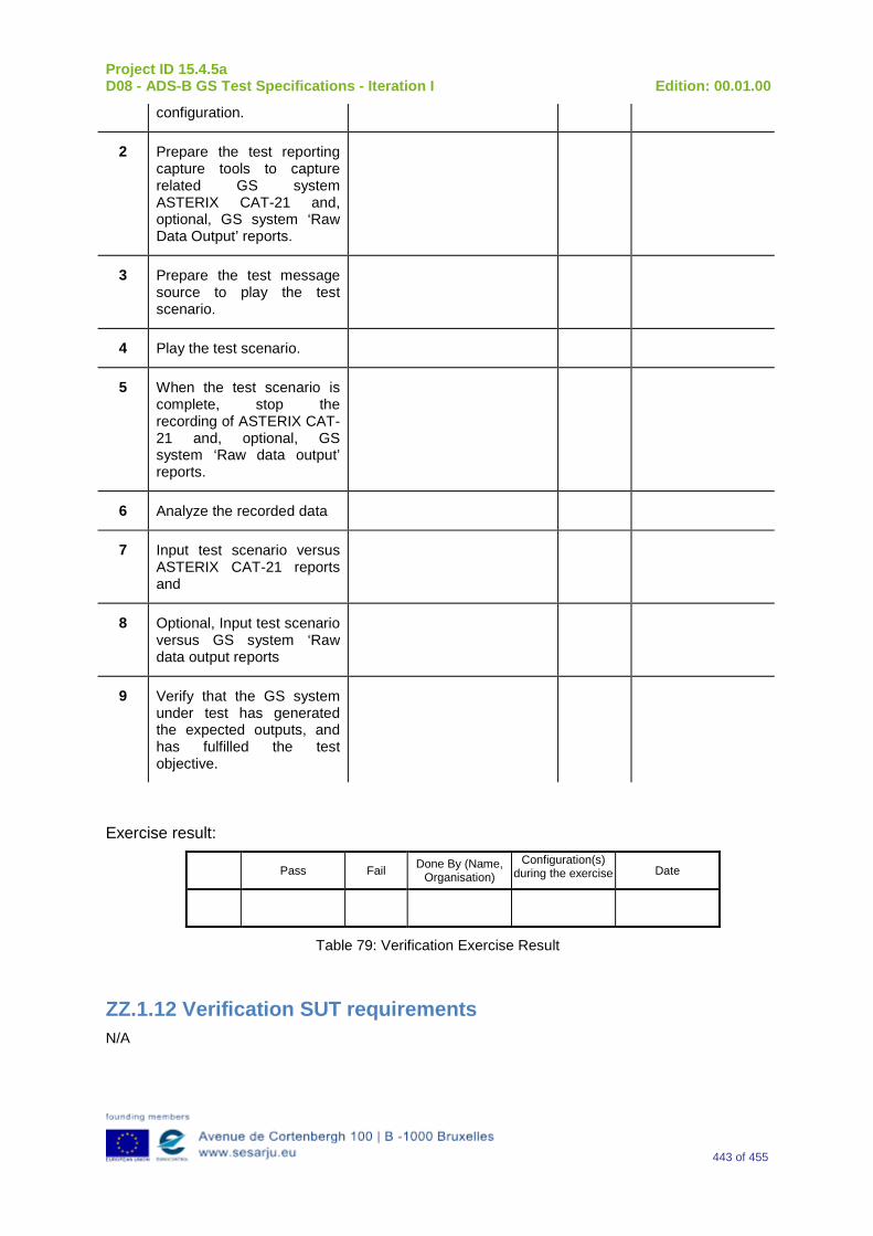
Project ID 15.4.5a D08 - ADS-B GS Test Specifications - Iteration I Edition: 00.01.00
443 of 455
configuration.
2 Prepare the test reporting capture tools to capture related GS system ASTERIX CAT-21 and, optional, GS system ‘Raw Data Output’ reports.
3 Prepare the test message source to play the test scenario.
4 Play the test scenario.
5 When the test scenario is complete, stop the recording of ASTERIX CAT-21 and, optional, GS system ‘Raw data output’ reports.
6 Analyze the recorded data
7 Input test scenario versus ASTERIX CAT-21 reports and
8 Optional, Input test scenario versus GS system ‘Raw data output reports
9 Verify that the GS system under test has generated the expected outputs, and has fulfilled the test objective.
Exercise result:
Pass Fail Done By (Name, Organisation)
Configuration(s) during the exercise Date
Table 79: Verification Exercise Result
ZZ.1.12 Verification SUT requirements N/A

Project ID 15.4.5a D08 - ADS-B GS Test Specifications - Iteration I Edition: 00.01.00
444 of 455
ZZ.1.13 Exercise Tool, Verification Technique and/or Platform
ADS-BGround Station
Power
ASTERIX(and Raw Data)
Recording
UTC Time Reference
RF Source(Message Generator)
The Exercise will be verified in a platform with the following foreseen tools/equipment:
-Ground Station ADS–B
-Message Generator
-ASTERIX (and Raw Data) Recording Tool
-Power Source
-UTC time Reference
The Item reported above will be capable to perform the functionalities reported below.
Ground Station ADS-B
The primary function of the 1090 GS is to receive 1090 MHz Mode S Extended Squitter messages, extract the data contained therein, and create appropriated ASTERIX Category 21 and 23 Reports (and optionally, Raw Data).
Message Generator
The Messages Generator will be capable to generate the data coming from the Remote System (ADS–B Ground Station or 1090 Receiver) like:
•Target data stream with inside the information extracted by the ADS–B message (ASTERIX CAT 21 in the case of Ground Station or Raw Data in the case that remote system is a 1090 MHz Receiver).
•Operational Data Stream with inside the Remote System’s Operational Status Information (ASTERIX CAT 23 in the case of Ground Station or Raw Data in the case that remote system is a 1090 MHz Receiver).
UTC Time Reference
The UTC Time reference is the solution adopted in the Test Scenario in order to provide the Synchronization in the Ground Station by UTC Time.
ASTERIX Recording Equipment
The ASTERIX recording equipment will be capable to record all ASTERIX reports sent from the 1090 ES Ground Station.
ZZ.1.14 Verification Platform needs See section 3.5 Verification Platform Needs.

Project ID 15.4.5a D08 - ADS-B GS Test Specifications - Iteration I Edition: 00.01.00
445 of 455
ZZ.1.15 Platform Configuration N/A
ZZ.1.16 Configuration(s) Identification of the Verification Platform N/A
ZZ.1.17 Links to other Verification Exercises N/A
ZZ.1.18 Representatively level/ limitations N/A
ZZ.2 Exercises Planning and management
ZZ.2.1 Activities N/A
ZZ.2.1.1 Preparatory activities Setup the tools/equipment listed in 3.5 and ZZ.1.13 in order to meet the Test Preconditions.
ZZ.2.1.2 Execution activities Play the scenario generating in the input the desired messages and record the relevant ASTERIX (and Raw Data) output.
ZZ.2.1.3 Post execution activities The post execution activities will be mainly focused on the analysis of recorded ASTERIX reports (and Raw Data reports). The analysis shall be done in order to verify the right information propagation as requested in each Test Scenario.
ZZ.2.2 Human Resources N/A
ZZ.2.3 Responsibilities in the exercise N/A
ZZ.2.4 Training N/A
ZZ.2.5 Time planning N/A
ZZ.2.6 Risks N/A
Project ID 15.4.5a D08 - ADS-B GS Test Specifications - Iteration I Edition: 00.01.00
446 of 455
ZZ.2.7 Errors and Observation handling N/A
ZZ.3 Analysis Specification
ZZ.3.1 Data collection methods The data collection during the test will be Qualitative. In fact after the test execution the analysis of ASTERIX Data will be performed verifying that the values reported in the output are in line with the values generated in the input.
ZZ.3.2 Analysis method N/A
ZZ.3.3 Data logging requirements The data logging requirements for this scenario will foresee at least ASTERIX CAT 21 items.
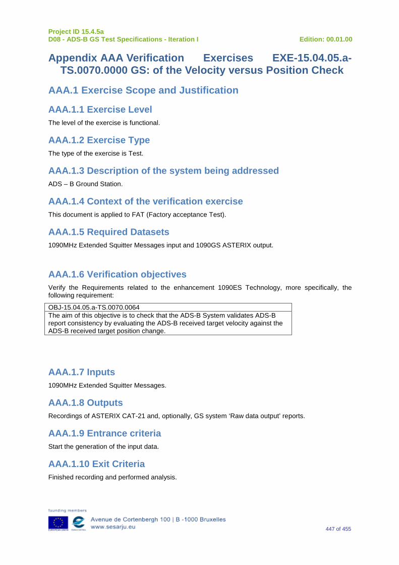
Project ID 15.4.5a D08 - ADS-B GS Test Specifications - Iteration I Edition: 00.01.00
447 of 455
Appendix AAA Verification Exercises EXE-15.04.05.a-TS.0070.0000 GS: of the Velocity versus Position Check
AAA.1 Exercise Scope and Justification
AAA.1.1 Exercise Level The level of the exercise is functional.
AAA.1.2 Exercise Type The type of the exercise is Test.
AAA.1.3 Description of the system being addressed ADS – B Ground Station.
AAA.1.4 Context of the verification exercise This document is applied to FAT (Factory acceptance Test).
AAA.1.5 Required Datasets 1090MHz Extended Squitter Messages input and 1090GS ASTERIX output.
AAA.1.6 Verification objectives Verify the Requirements related to the enhancement 1090ES Technology, more specifically, the following requirement:
OBJ-15.04.05.a-TS.0070.0064 The aim of this objective is to check that the ADS-B System validates ADS-B report consistency by evaluating the ADS-B received target velocity against the ADS-B received target position change.
AAA.1.7 Inputs 1090MHz Extended Squitter Messages.
AAA.1.8 Outputs Recordings of ASTERIX CAT-21 and, optionally, GS system ‘Raw data output’ reports.
AAA.1.9 Entrance criteria Start the generation of the input data.
AAA.1.10 Exit Criteria Finished recording and performed analysis.
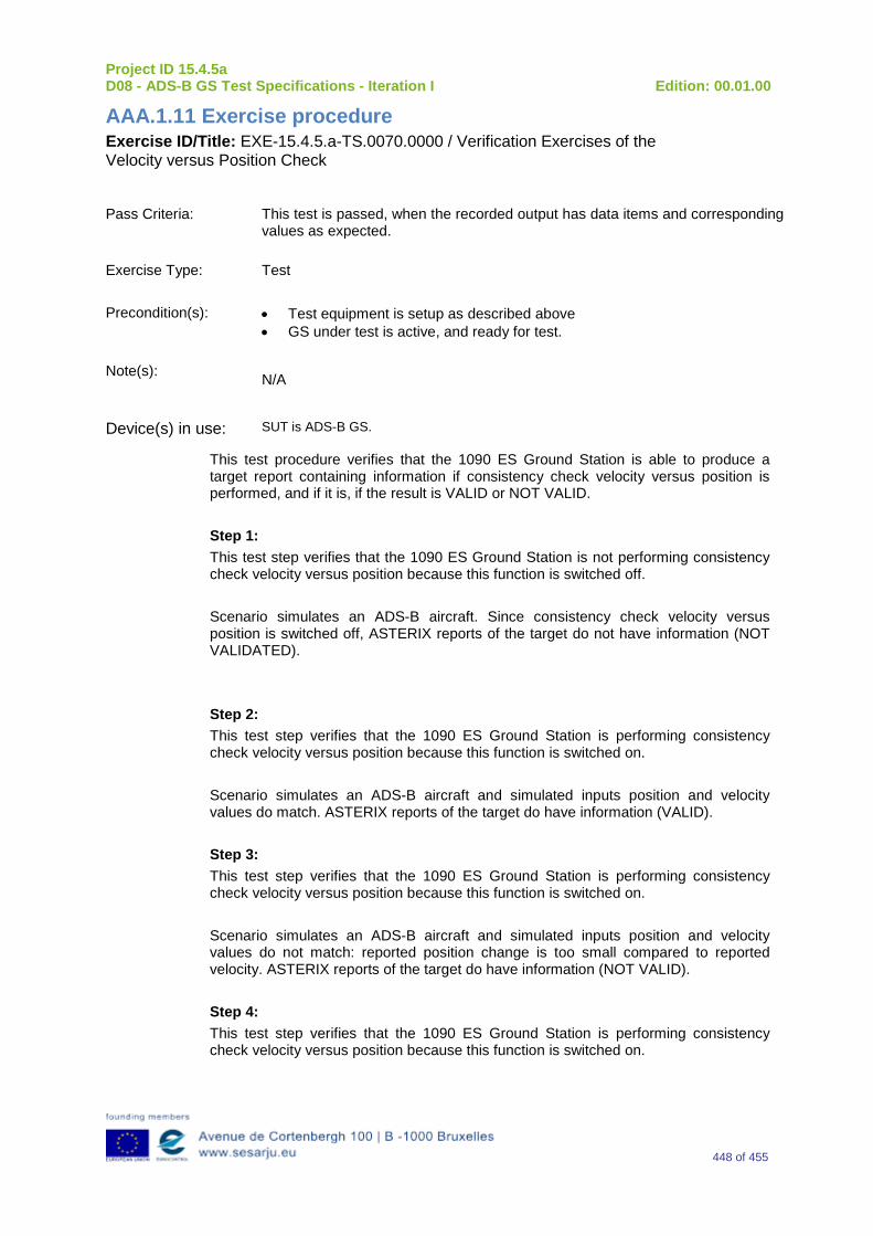
Project ID 15.4.5a D08 - ADS-B GS Test Specifications - Iteration I Edition: 00.01.00
448 of 455
AAA.1.11 Exercise procedure Exercise ID/Title: EXE-15.4.5.a-TS.0070.0000 / Verification Exercises of the Velocity versus Position Check
Pass Criteria: This test is passed, when the recorded output has data items and corresponding
values as expected.
Exercise Type: Test
Precondition(s): • Test equipment is setup as described above • GS under test is active, and ready for test.
Note(s): N/A
Device(s) in use: SUT is ADS-B GS.
This test procedure verifies that the 1090 ES Ground Station is able to produce a target report containing information if consistency check velocity versus position is performed, and if it is, if the result is VALID or NOT VALID. Step 1: This test step verifies that the 1090 ES Ground Station is not performing consistency check velocity versus position because this function is switched off. Scenario simulates an ADS-B aircraft. Since consistency check velocity versus position is switched off, ASTERIX reports of the target do not have information (NOT VALIDATED). Step 2: This test step verifies that the 1090 ES Ground Station is performing consistency check velocity versus position because this function is switched on. Scenario simulates an ADS-B aircraft and simulated inputs position and velocity values do match. ASTERIX reports of the target do have information (VALID). Step 3: This test step verifies that the 1090 ES Ground Station is performing consistency check velocity versus position because this function is switched on. Scenario simulates an ADS-B aircraft and simulated inputs position and velocity values do not match: reported position change is too small compared to reported velocity. ASTERIX reports of the target do have information (NOT VALID). Step 4: This test step verifies that the 1090 ES Ground Station is performing consistency check velocity versus position because this function is switched on.
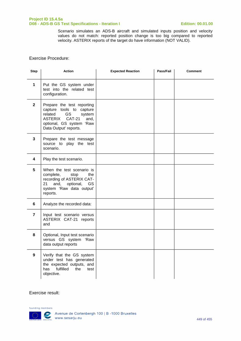
Project ID 15.4.5a D08 - ADS-B GS Test Specifications - Iteration I Edition: 00.01.00
449 of 455
Scenario simulates an ADS-B aircraft and simulated inputs position and velocity values do not match: reported position change is too big compared to reported velocity. ASTERIX reports of the target do have information (NOT VALID).
Exercise Procedure:
Step Action Expected Reaction Pass/Fail Comment
1 Put the GS system under test into the related test configuration.
2 Prepare the test reporting capture tools to capture related GS system ASTERIX CAT-21 and, optional, GS system ‘Raw Data Output’ reports.
3 Prepare the test message source to play the test scenario.
4 Play the test scenario.
5 When the test scenario is complete, stop the recording of ASTERIX CAT-21 and, optional, GS system ‘Raw data output’ reports.
6 Analyze the recorded data:
7 Input test scenario versus ASTERIX CAT-21 reports and
8 Optional, Input test scenario versus GS system ‘Raw data output reports
9 Verify that the GS system under test has generated the expected outputs, and has fulfilled the test objective.
Exercise result:
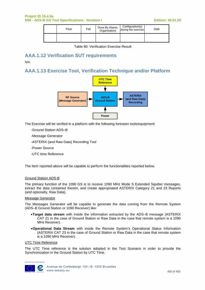
Project ID 15.4.5a D08 - ADS-B GS Test Specifications - Iteration I Edition: 00.01.00
450 of 455
Pass Fail Done By (Name, Organisation)
Configuration(s) during the exercise Date
Table 80: Verification Exercise Result
AAA.1.12 Verification SUT requirements N/A
AAA.1.13 Exercise Tool, Verification Technique and/or Platform
ADS-BGround Station
Power
ASTERIX(and Raw Data)
Recording
UTC Time Reference
RF Source(Message Generator)
The Exercise will be verified in a platform with the following foreseen tools/equipment:
-Ground Station ADS–B
-Message Generator
-ASTERIX (and Raw Data) Recording Tool
-Power Source
-UTC time Reference
The Item reported above will be capable to perform the functionalities reported below.
Ground Station ADS-B
The primary function of the 1090 GS is to receive 1090 MHz Mode S Extended Squitter messages, extract the data contained therein, and create appropriated ASTERIX Category 21 and 23 Reports (and optionally, Raw Data).
Message Generator
The Messages Generator will be capable to generate the data coming from the Remote System (ADS–B Ground Station or 1090 Receiver) like:
•Target data stream with inside the information extracted by the ADS–B message (ASTERIX CAT 21 in the case of Ground Station or Raw Data in the case that remote system is a 1090 MHz Receiver).
•Operational Data Stream with inside the Remote System’s Operational Status Information (ASTERIX CAT 23 in the case of Ground Station or Raw Data in the case that remote system is a 1090 MHz Receiver).
UTC Time Reference
The UTC Time reference is the solution adopted in the Test Scenario in order to provide the Synchronization in the Ground Station by UTC Time.
Project ID 15.4.5a D08 - ADS-B GS Test Specifications - Iteration I Edition: 00.01.00
451 of 455
ASTERIX Recording Equipment
The ASTERIX recording equipment will be capable to record all ASTERIX reports sent from the 1090 ES Ground Station.
AAA.1.14 Verification Platform needs See section 3.5 Verification Platform Needs.
AAA.1.15 Platform Configuration N/A
AAA.1.16 Configuration(s) Identification of the Verification Platform N/A
AAA.1.17 Links to other Verification Exercises N/A
AAA.1.18 Representatively level/ limitations N/A
AAA.2 Exercises Planning and management
AAA.2.1 Activities N/A
AAA.2.1.1 Preparatory activities Set up the tools/equipment listed in 3.5 and AAA.1.13 in order to meet the Test Preconditions.
AAA.2.1.2 Execution activities Play the scenario generating in the input the desired messages and record the relevant ASTERIX (and Raw Data) output.
AAA.2.1.3 Post execution activities The post execution activities will be mainly focused on the analysis of recorded ASTERIX reports (and Raw Data reports). The analysis shall be done in order to verify the right information propagation as requested in each Test Scenario.
AAA.2.2 Human Resources N/A
AAA.2.3 Responsibilities in the exercise N/A
AAA.2.4 Training N/A
Project ID 15.4.5a D08 - ADS-B GS Test Specifications - Iteration I Edition: 00.01.00
452 of 455
AAA.2.5 Time planning N/A
AAA.2.6 Risks N/A
AAA.2.7 Errors and Observation handling N/A
AAA.3 Analysis Specification
AAA.3.1 Data collection methods The data collection during the test will be Qualitative. In fact after the test execution the analysis of ASTERIX Data will be performed verifying that the values reported in the output are in line with the values generated in the input.
AAA.3.2 Analysis method N/A
AAA.3.3 Data logging requirements The data logging requirements for this scenario will foresee at least ASTERIX CAT 21 items.
Project ID 15.4.5a D08 - ADS-B GS Test Specifications - Iteration I Edition: 00.01.00
453 of 455
Appendix BBB Preliminary Coverage Matrix
The project intends to import all requirements defined in this document (Verification Method, associated Verification Objectives and Verification Exercise in which these Verification Objectives are embedded) as well as the lower level derived requirements as specified in Deliverables D5 and D18, into a requirements management tool (like DOORS).
Such a tool will then generate an overall traceability matrix which could be included in this document at a later stage (i.e. in one of the forthcoming iterations).

Project ID 15.4.5a D08 - ADS-B GS Test Specifications - Iteration I Edition: 00.01.00
454 of 455
-END OF DOCUMENT -


![T-76.4115 Iteration Demo BaseByters [I1] Iteration 04.12.2005](https://img.pdfslide.us/doc/110x75/56649cff5503460f949d053f/t-764115-iteration-demo-basebyters-i1-iteration-04122005.jpg)