Embed Size (px)
Citation preview
2496 IEEE TRANSACTIONS ON VISUALIZATION AND COMPUTER GRAPHICS, VOL. 20, NO. 12, DECEMBER 2014
1077-2626 © 2014 IEEE. Personal use is permitted, but republication/redistribution requires IEEE permission.See http://www.ieee.org/publications_standards/publications/rights/index.html for more information.
ADR - Anatomy-Driven Reformation
Jan Kretschmer, Grzegorz Soza, Christian Tietjen, Michael Suehling, Bernhard Preim, and Marc Stamminger
Fig. 1. Several results generated with our Anatomy-Driven Reformation approach (ADR). By taking the individual shape of an anatom-ical structure into account, our method allows generating flat reformations that provide comprehensive overviews. From left to right:pelvis ADR, rib cage ADR and feet ADR.
Abstract—Dedicated visualization methods are among the most important tools of modern computer-aided medical applications.Reformation methods such as Multiplanar Reformation or Curved Planar Reformation have evolved as useful tools that facilitatediagnostic and therapeutic work. In this paper, we present a novel approach that can be seen as a generalization of MultiplanarReformation to curved surfaces. The main concept is to generate reformatted medical volumes driven by the individual anatomicalgeometry of a specific patient. This process generates flat views of anatomical structures that facilitate many tasks such as diagnosis,navigation and annotation. Our reformation framework is based on a non-linear as-rigid-as-possible volumetric deformation schemethat uses generic triangular surface meshes as input. To manage inevitable distortions during reformation, we introduce importancemaps which allow controlling the error distribution and improving the overall visual quality in areas of elevated interest. Our methodseamlessly integrates with well-established concepts such as the slice-based inspection of medical datasets and we believe it canimprove the overall efficiency of many medical workflows. To demonstrate this, we additionally present an integrated visualizationsystem and discuss several use cases that substantiate its benefits.
Index Terms—Medical Visualization, Volume Reformation, Viewing Algorithms
1 INTRODUCTION
Computer-generated visualizations play an important role in modernclinical practice since they enable a very flexible and efficient inspec-tion of radiological data. The importance and the positive impact ofcomputer-aided workflows on the overall efficiency of today’s radi-ological practice is well documented by extensive studies [31, 32].Moreover, some studies already predict an alarming shortage in diag-nostic radiologists over a 30 year horizon [3]. Thus, one key objec-tive of medical visualization is to improve the efficiency of radiologi-cal work in an increasingly demanding environment. This means thattasks have to be facilitated for faster processing without sacrificing anyaccuracy or completeness.
• Jan Kretschmer is with the Department of Computer Graphics, FAUErlangen, and Siemens Healthcare Computed Tomography, Forchheim,Germany. E-mail: [email protected].
• Grzegorz Soza is with Siemens Healthcare Computed Tomography,Forchheim, Germany. E-mail: [email protected].
• Christian Tietjen is with Siemens Healthcare Computed Tomography,Forchheim, Germany. E-mail: [email protected].
• Michael Suehling is with Siemens Healthcare Computed Tomography,Forchheim, Germany. E-mail: [email protected].
• Bernhard Preim is with the Department of Simulation and Graphics,Otto-von-Guericke University of Magdeburg, Germany. E-mail:[email protected].
• Marc Stamminger is with the Department of Computer Graphics, FAUErlangen, Germany. E-mail: [email protected].
Not only in the oncological and the trauma-related field, reconstruc-tions from Computed Tomography (CT) are often the basis for bothinitial diagnosis and ongoing treatment. Down to the present day, thegold standard in diagnostic radiological practice is a slice-wise inspec-tion of standard orthogonal views. This direct inspection of recon-structed slices is not ideal for many tasks since anatomical structuresare generally not aligned with the CT coordinate system and may ex-hibit complex shapes. The detection of rib metastases or fractures,for instance, usually involves the inspection of hundreds of slices ina CT scan. Since standard orthogonal reformations (i.e. axial, sagit-tal, coronal) provide oblique cuts through ribs, it is a tedious and errorprone task to reliably track longitudinal changes as needed for diagno-sis [7]. Once detected, metastases have to be documented. This meansthey have to be tracked back to the corresponding vertebra to allowfor a proper anatomical labeling. Using slice-based navigation, thisbecomes a tedious task since the cross-sections of a rib bone usuallyexpose a high drift between slices. Recent segmentation and visual-ization methods have started to pick up on this by proposing solutionsthat provide centerline-driven normalized views to radiologists [43].
Similarly, pelvic bone lesions can exhibit a large variety of appear-ances making their detection and classification a tedious task [13]. Thecomplex anatomy of the pelvic bone further complicates the assess-ment of lesion geometry (i.e. size and shape) and anatomical locationwhen using standard orthogonal reformations of the CT data set.
The detection and classification of fractures of the skull and theskull base is an important task when dealing with traumatic head in-juries. A user study showed that anatomy-aligned curved projectionscan increase the fracture detection rate compared to traversal views[34]. In addition, the authors show that detection can be performedabout four times faster compared to standard views.
In this paper, we present a generic reformation framework that al-
For information on obtaining reprints of this article, please sende-mail to: [email protected].
Manuscript received 31 Mar. 2014; accepted 1 Aug. 2014 ate ofpublication 2014; date of current version 2014.11 Aug. 9 Nov.
D.
Digital Object Identifier 10.1109/TVCG.2014.2346405

2497KRETSCHMER ET AL.: ADR - ANATOMY-DRIVEN REFORMATION
lows to generate Anatomy-Driven Reformations (ADRs) of complexanatomical structures. The reformatted volumes have a highly nor-malized character since they map patient-specific curved structures toa consistent flat setting. ADRs do not aim at replacing original recon-structions but rather at facilitating common tasks like navigation or an-notation. For instance, linking ADR views with standard orthogonalreconstructions, enables more efficient workflows for common onco-logical and trauma injury-related tasks without sacrificing any imagefidelity. In Section 7 we provide more detailed examples for clinicallymotivated applications that directly benefit from precomputed ADRs.
2 RELATED WORK
The end-to-end reformation framework, we present in this paper,touches many fields of medical visualization and computer graphics.Hence, in this section we will give a brief overview over the most rel-evant related work and point to summary articles for further reading.
2.1 Anatomy-Aware Visualization of Medical Data
The generation of meaningful and diagnostically relevant visualiza-tions of medical datasets is a challenging tasks. Due to the highgeometrical complexity of the human body, major problems includemutual occlusions, self-occlusions and general visual clutter. Sincethe inter-patient variation of anatomical geometry is usually relativelysmall, an immense variety of visualization algorithms has been devel-oped, many of which explicitly take advantage of the shape of particu-lar anatomical structures. In the following, we give an overview on thefield of anatomically motivated projection and reformation techniques.We then discuss some previously proposed end-to-end approaches.
2.1.1 Projection Methods
Projection-based visualization techniques constitute a common way toenhance raw medical data and they have been proposed in many dif-ferent flavors and for broadly varying tasks. A common approach is toapproximate organs or other anatomical structures by geometric primi-tives like spheres [19], cylinders [28] or even planes [25] that allow fora straight-forward projection of surrounding tissue. These methods areusually tweaked for specific applications and often focus on dedicatedtransfer function designs. Typical applications include projections ofcardiac areas or tumors [33]. With simplicity and intuitiveness beingtheir strength, closed-form primitives often fail to sufficiently capturethe geometry of the anatomical structure being projected, leading todistortions and occlusions.
2.1.2 Surface Reformation Methods
To allow for a more flexible inspection of medical datasets, Multipla-nar Reformation (MPR) [15] was proposed to resample reconstructedCT volumes in arbitrarily oriented planes. Curved Planar Reformation(CPR) [17] and its derivatives [1, 18, 26] provide even more flexiblecuts through datasets that are driven by single geometric centerlines orcomplex centerline graphs. CPRs are a common tool in vessel visual-ization since they generate cuts that allow for a thorough inspection ofvessel lumen and that include valuable anatomical context. In contrastto MPRs, CPRs are driven by patient-specific anatomical informationwhich ultimately allows condensing more information into a single ro-tatable 2D view. Saroul et al. present similar reformation results forcurved cut surfaces [37]. Their mapping algorithm also allows to pre-serve distances in fixed directions [36] but is generally limited to cutsurfaces. The main problem with current reformation-like approachesis that they usually resort to some kind of projection. Moreover, theyusually do not provide an explicit handling for the distortions that ariseand only parameterize single cuts instead of volumetric regions.
2.1.3 Visualization Frameworks
Dedicated visualization frameworks have been proposed for severalanatomical structures. Colon flattening methods [2, 14, 42] for in-stance, constitute a prominent example for efforts to improve a te-dious and error-prone diagnostic task of modern cancer prevention.
Because of their complex shape and size, colons are extremely chal-lenging to visualize. To preserve the distinct shape of important fea-tures like polyps in an expressive manner, colon unfolding methodsare usually particularly concerned with paremeterization and occlu-sion issues. To speed up the task of detecting and labeling rib bonelesions, a centerline-driven viewing approach was presented in [43].The method provides a rotatable CPR for each rib and arranges allCPRs in an atlas-like view. To provide cranial unfoldings, a dedicatedmethod for trauma-related readings was developed in [34]. The al-gorithm basically drops an elastic grid over the head of a patient towrap and parameterize the skull bone. Subsequently, the grid is usedto compute projections which, as the article confirms in a study, leadto an improved sensitivity for the detection of skull fractures. For thediagnosis of coronary artery diseases, Termeer et al. present the volu-metric bulls eye plot [41] as an extension to the well established bullseye plot method. Their method generates a continuous thick parame-terization of the myocardium that allows for different unfoldings.
2.2 Conformal Mappings and Volumetric DeformationProviding some kind of normalized or flattened view of an originallymore articulated structure generally introduces inevitable distortions.There are two related fields, one dealing with mappings between man-ifolds and one dealing with mappings between volumes. We willrefer to these as surface parameterization and volume parameteriza-tion respectively. The general problem of finding low-distortion map-pings between objects of different shape is a well known problemin computer graphics. It appears in texture mapping [22], ambientspace warping and surface-based mesh deformation [40] and volumet-ric mesh deformation [46].
Conformal mappings preserve angles, which is an important prop-erty when trying to preserve similarity during mapping. The confor-mality of a mapping plays an important role in image registration tasksin computer vision [24, 44] and medical image registration [10, 47].As discussed in [23], however, conformal surface parameterizationsstill allow for local or global scaling to occur. This leads to a blow-up or a shrinkage of certain regions. To overcome this, the authorsof [23] borrow from the As-Rigid-As-Possible (ARAP) deformationparadigm introduced by Sorkine et al. [40] and propose a surfaceparameterization framework that allows to optimize for a trade-offbetween local conformity (preservation of angles) and local rigidity(preservation of angles and lengths).
Due to this local rigidity preservation and its efficient nature, theARAP approach has been adopted for volume-aware interactive defor-mation methods based on grids [11, 46] and skeletons [45]. Becauseof the high computational burden, volumetric deformations methodsoften employ coarse-to-fine proxy grids that use different deforma-tion methods in each level (i.e. higher quality on coarser levels to fastapproximations in fine levels) [11]. In [21], volumetric deformationmethod based on interior radial basis functions (IRBFs) is proposed.The key idea is to use shape-interior distances instead of Euclidean dis-tances which allows deformations to adhere to the interior of a shape.By this, close-by thin structures like limbs can be deformed separately,whereas they would influence eachother in classical ambient space de-formation based on Euclidean distance metrics.
2.3 Model-Based Medical SegmentationMedical image segmentation is a very common task that has givenrise to a large variety of different approaches. Since the method wepropose is based on surfaces that preferably run through the centerof anatomical structures, from our perspective segmentation is a pre-processing step. Model-based image segmentation is particularly wellsuited for our application since usually the approximate shape of ananatomical structure and its medial surface is known beforehand. Thebasic strategy of model-based methods such as Active Shape Mod-els [6] or Active Appearance Models [5] is to exploit this geometricand intensity-based knowledge to achieve segmentations with inher-ent plausibility. Usually, parametric models are based on observationsdrawn from a statistical data base [4, 38]. For segmentation, mod-els are often initialized with the statistical mean of the parameter set.

2498 IEEE TRANSACTIONS ON VISUALIZATION AND COMPUTER GRAPHICS, VOL. 20, NO. 12, DECEMBER 2014
This parameter set is then optimized until similarity metrics betweenthe appearance of the model and the target dataset reach a minimum.Annotating the statistical model with a center surface, for example us-ing vertex skinning or similar techniques, allows for the simultaneousgeneration of a center surface fit during segmentation.
Medical image registration [24, 44, 47] produces deformation fieldsthat enable warping between a reference dataset and a target dataset.Using this deformation field, annotations in the reference dataset, likecenter surfaces can be mapped to the patient-specific setting. Medialsurfaces [8, 20] can also serve as a starting point to generate meshesthat approximately run through the center of a structure.
3 CONTRIBUTION AND OVERVIEW
Current anatomy-aware reformation and visualization methods tend tofocus on one specific anatomical structure [1, 18, 34, 43] and thus lackgeneral applicability. While some methods do enable slicing by mov-ing curved surfaces [36, 37] they do not provide a global minimizationof distortion artifacts between slices. Volumetric deformation meth-ods, on the other hand, are usually designed for generality and providea powerful basis to create low-distortion mappings between structures.Current applications to medical visualization [11], however, lack adap-tation to the clinical scenarios that motivated our work, i.e. the creationof anatomy-aligned thick reformations (see Section 7.1).
We propose an extension of the ARAP surface parameterizationscheme proposed in [23] to a thick volumetric region around a surfacemesh. It allows users to reformat (i.e. flatten) the surrounding of cutsurfaces through medical datasets and can be viewed as an extensionof standard Multiplanar Reformation to curved surfaces. Our methoddescribes a hybrid approach between a single cut surfaces [23] andvolumetric deformation [11, 46]. Similar to conventional MPRs ourmethod creates reformations based on a surface. However, since weallow surfaces to be curved, distortions in the deformed region need tobe managed during flattening. This is where we draw from the fieldvolumetric deformation to globally minimize distortions.
As a key contribution, our method generates reformations that arealigned with the patient-specific geometry of an anatomical structure.This allows us to create Anatomy-Driven Reformations (ADR) tai-lored to a large variety of entirely different anatomical structures.Our formulation thus provides a means to integrate many differentapplications into a single pipeline. We demonstrate this by propos-ing a reformation-based application that enables a fast exploration ofcomplex bone structures. In addition, our formulation includes animportance-based optimization scheme to manage distortions and toincrease the overall visual quality.
The basic input for our method is an ADR surface, represented asa triangulated mesh in world space that runs through an anatomicalstructure of interest. The ADR surface should usually be located inthe center of the structure since its surrounding to both sides will beparameterized by the reformation pipeline. The output of our methodconsists of flat reformatted medical volumes that can be inspected withwell known approaches like slicing. To allow for this kind of unfoldedanatomy-aligned slicing, the ADR surface needs to be open.
Figure 2 illustrates our basic pipeline and the most important struc-tures involved. Our framework consists of three main steps:
1. Offset surface computation: In the first step we compute copiesof the surface mesh with negative and positive displacements.The region between the resulting three layers defines the thick-ness and the content of the final reformation.
2. Deformation: We then compute a flat embedding of the threesurfaces in three flat stacked layers. The mapping that corre-sponds to a volume parameterization explicitly minimizes intra-layer distortions and shearing errors between layers.
3. Reformation: After the ADR layers are optimized, we use thestacked setting to resample a reformatted volume. The corre-spondence to world space can be used for atlas-like navigationand annotation.
1.2.
3.
ADR Surface Offset Surfaces ADR Layers
Fig. 2. Basic outline and terminology of our reformation pipeline usingthe example of a skull reformation (renderings are clipped for clearer vis-ibility). Offset surfaces need to be computed for the initial ADR surfaceto parameterize its surrounding volume (1). By deforming the resultingmesh to a flat layered setting, a mapping is induced (2). Resampling theoriginal dataset results in a reformatted flat volume (3).
4 ANATOMY-DRIVEN REFORMATION (ADR)
The key concept of our visualization method is to generate reformat-ted views of medical datasets based on a given 2D ADR surface em-bedded in 3D space. In this section we will first lay out the pipelinefor a surface-based reformation framework which corresponds to theparameterization method described in [23]. We will then extend themethod to a volumetric approach that generates a paremeterization forthe surrounding area of the ADR surface.
4.1 Input Data
The ADR surface mesh M is described by a list of vertices V withcoordinates vi ∈ R3, i = 0 . . .n− 1, a list of triangles T and a list ofhalf edges HE. To be able to generate flattened versions of 3D meshes,one restriction we impose is that the meshes are not closed, i.e. thatthey have at least one border so they can be flattened. In practice, thisrestriction does not pose significant problems, since closed meshes canbe cut open interactively or automatically beforehand [39].
4.2 Surface-Based ADR
When reformatting a medical volume, the goal is to map M to a flatrepresentation M′ with vertices v′i ∈ R2. This introduces distortionswhich should be minimized to provide a reformation that preservesthe anatomical geometry as much as possible. For this, we extend themesh parameterization method described in [23]. In this approach, thesurface mesh is viewed as a set of connected cells. Each cell corre-sponds to a triangle of the mesh. This means each cell can be em-bedded in a plane trivially since triangles by definition only span a 2Dsubspace. When computing the mapping from the mesh embedded inR3 to the planar embedding in R2, the key idea is to keep every in-dividual cell as rigid as possible while at the same time forcing theshared vertices of the cells (i.e. the triangle corners) to coincide.
To achieve this, we start off with an initial flat embedding M′0 of
M and use an iterative non-linear optimization scheme that uses twophases per iteration, as proposed in [23]. In the first (local) optimiza-tion phase, for every triangle a 2D rotation Rt needs to be computedthat best rotates the original undeformed triangle to the current solu-tion. The second (global) phase takes care of stitching the individuallyrotated triangles tt to a mesh with globally consistent vertex positions.This is necessary since the optimal rotations are computed per triangleand are thus not consistent across the mesh.
4.2.1 Initial Flat Triangulation
The iterative optimization scheme needs an initial flat embedding ofthe mesh in 2D. As stated in [23] there are several interchangeableways to compute this initial solution for the vertex positions v′i. Be-cause of its simplicity we use an approach that computes an initialharmonic triangulation, similar to the one proposed by Floater [12].For this we collect all boundary vertices of the mesh and distributethem in consecutive order along the circumcircle of a disc. We thenuse these outer vertices as boundary conditions and solve the following

2499KRETSCHMER ET AL.: ADR - ANATOMY-DRIVEN REFORMATION
discretized linear Poisson system for all free vertices v′i, i /∈ Ω .
#V (i)v′i − ∑j∈V (i)∩Ω
v′j = ∑j∈V (i)∩Ω
v′j ,∀i /∈ Ω (1)
Here, V (i) denotes the set of direct neighbors of a vertex vi and #V (i)is the size of the set (i.e. the valence of the vertex). Ω is the set of con-strained boundary vertices which are on the right-hand side of Equa-tion 1 and which are known. Because of the Laplacian mean valueproperty, the resulting vertex positions lead to a flat mesh that doesnot fold and thus constitutes a well-behaved initial solution for thesubsequent iterative optimization scheme. The initialization process isillustrated in Figure 3.
boundary
Fig. 3. Left: 3D ADR Surface for a pelvis reformation with some bound-ary vertices marked. Center: Initial flat triangulation. Boundary verticesare distributed onto a circle and serve as boundary conditions for har-monic vertex positions based on the connectivity of the mesh. Right:Final flat triangulation after 20 iterations.
4.2.2 Local Phase - Computing Triangle RotationsFollowing [23], the purpose of the local phase is to explicitly computea 2D similarity transformation or a rigid transformation Rt : R2 →R2.The purpose of Rt is to align the original, undeformed triangle to thegeometry of the current solution. To prevent scaling-induced distor-tions from creeping into our final mapping, we only allow rotations.This means Rt constitutes an isometric mapping that preserves the areaand the angles of each original triangle. To compute rotations, we firstneed to find a shape-preserving 2D embedding of all original triangles.For this we create an orthonormal basis matrix aligned with each tri-angle. We then transpose (i.e. invert) it and drop the superfluous thirdcomponent to get a mapping to the triangle tangent space Nt :R3 →R2
Nt(x) =(vb −va
‖vb −va‖n× (vb −va)
‖n× (vb −va)‖)T (x− 1
3(va +vb +vc)),
n =(vc −va)× (vb −va)
‖(vc −va)× (vb −va)‖
(2)
where a,b and c denote the vertex indices of triangle tt . For everytriangle tt we can use the mapping Nt to create an arbitrarily rotated2D embedding t0
t . To find the optimal rotation between this originaltriangle (v0
a,v0b,v
0c)t = (Nt(va),Nt(vb),Nt(vc)) and the deformed tri-
angle in the current solution (v′a,v′b,v′c)t we use Kabsch’s algorithm
[16]. For this we need to compute the singular value decompositionA =V SW T of the covariance matrix A of the centroid-aligned trianglevertices.
A = v0a(v
′a − c)T +v0
b(v′b − c)T +v0
c(v′c − c)T
where c = 13 (v
′a +v′b +v′c) is the centroid of the current triangle. The
rotation is then defined as
Rt =W(
1 00 sign(det(WV T ))
)V T
4.2.3 Global Phase - Solving for Vertex PositionsTo find consistent vertex positions for the current set of rotations R,we minimize the following energy functional taken from [23]
EARAP(v′i,R) =12 ∑(i, j)∈HE
cot(Θi, j)‖(v′i−v′j)−Rt(i, j)(v0i −v0
j)‖2 (3)
where cot(Θi, j) are cotangent weights as presented in [30], HE is theset of half edges in the mesh, Rt(i, j) is the rotation for the triangle as-sociated with half edge (i, j), v0
i ∈ R2 are the vertex positions of theoriginal triangle embeddings and v′i ∈ R2 are the target vertex posi-tions. By fixing the rotations to the ones computed in the local phase,EARAP becomes linear. The global phase thus boils down to taking theaverage rotation of the adjacent triangles of an edge, rotating the edgesof the original embedding in 2D and finding vertices v′i whose edgesminimize the deviation from these (prescribed) edges in a least squaressense. Setting the gradient of the energy in Equation 3 with respect tov′i to zero results in the following set of linear equations
∑j∈V (i)
(cot(Θi, j)+ cot(Θ j,i))(v′i −v′j)
= ∑j∈V (i)
(cot(Θi, j)Rt(i, j) + cot(Θ j,i)Rt( j,i))(v0i −v0
j)
∀i = 1 . . .n−1
(4)
Repeatedly computing rotations and then solving the correspondinglinear system for the vertex positions v′i results in a consistent 2D meshwhere every triangle is as close to its original shape as possible.
uxuy
Fig. 4. Top: Volume rendering of a pelvic CT scan and the ADR surfacemesh in 3D. Bottom: The flat parameterization of the surface mesh inADR image space. For sampling, the marked triangle was enlisted atall highlighted pixels. The green points are the pixels that are actuallyincluded in the triangle. They are mapped to the 3D setting to sampledraw intensity samples from the original dataset.
4.2.4 Resampling
Once the final 2D vertex positions v′i are computed, in conjunctionwith the original mesh embedded in 3D, they allow for a piece-wiselinear mapping between the domain of the dataset and the 2D domain.To generate an ADR image of a certain target resolution ADRresx ×ADRresy, we compute axis-aligned bounds v′min and v′max for the 2Dembedding of the mesh and map the coordinates to the ADR imagespace
ui =
(uixuiy
)=
(v′ix −v′minx)
ADRresxv′maxx−v′minx
(v′iy −v′miny)ADRresy
v′maxy−v′miny
. (5)
To determine the intensity (or color) value of a pixel in the ADRimage, we first need to find the triangle of the flattened mesh that cov-ers the respective pixel. After this we compute the barycenteric coor-dinates of the pixel center to transform it to the 3D domain using theoriginal mesh coordinates vi. Sampling the volume at the resulting po-sition gives the intensity value for the corresponding pixel in the ADRimage. To speed up the search task of finding the triangle that covers aparticular pixel, we compute a lookup table. For this we take the axis-aligned bounds of every triangle and enlist the triangle in a per-pixellist of every pixel covered by the bounds. Using the per-pixel list dur-ing sampling, barycentric coordinates only have to be computed for asmall local subset of the triangles. Figure 4 illustrates the ADR imagesampling process.

2500 IEEE TRANSACTIONS ON VISUALIZATION AND COMPUTER GRAPHICS, VOL. 20, NO. 12, DECEMBER 2014
4.3 Volumetric ReformationCreating an ADR image as described in the previous section only gen-erates a reformatted 2D image of a singular cut surface. When in-specting volumetric medical datasets, a common task is to examinethe surroundings of a particular site by viewing several adjacent slicesof the reconstructed image. This is commonly referred to as slicing.To provide a flexible visualization system, that is not limited to a sin-gle surface in 3D we extend our method to parameterize not only theADR surface, but also the surrounding volume.
4.3.1 Normal-Based Volume ParameterizationOne way to parameterize the surrounding is to compute offset sur-faces. Computing offset surfaces is a common task in computer graph-ics [29, 35]. The most obvious way to generate offset surfaces is todisplace the mesh vertices in the direction of the normal. To generatea volume parameterization for the surrounding of the ADR surface, wecompute two displaced copies of the original mesh, one with an offsetin negative and one in positive direction of the normal v− = v−dn andv+ = v+dn. Here, d denotes the offset distance which corresponds tothe maximum distance that can be inspected in the final reformation.To generate reformations with consistent thickness, we assume d tobe constant across the whole ADR surface which results in a stack ofthree layered meshes as illustrated in Figure 5.
A straight-forward way to extend the surface-based reformation ap-proach (see Section 4.2) to a volumetric approach, is to flatten thecenter ADR layer only and to apply the same flat geometry to the off-set surfaces. This keeps the reformatted triangle shapes constant in thelayer offset dimension and leads to a stack of extruded triangles as il-lustrated in Figure 5. Analogously to the sampling strategy presentedin Section 4.2.4, this setup creates a mapping between the reformattedspace and original 3D space which is, however, volumetric.
One problem with this approach is that global and local self-intersections frequently occur when computing the displaced offsetmeshes. To reduce self-intersections, we apply several iterations ofa Laplacian smoothing kernel [27] to the displaced vertex positions.The mean-value property of the Laplacian usually resolves local self-intersections and leads to generally smoother offset meshes. However,the displaced vertices will no longer lie on the normal-rays of the ver-tices of the ADR surface, which will lead to distortions when using aconstant stacked reformation approach as depicted in Figure 5.
4.3.2 As-Rigid-As-Possible Volume ParameterizationSince ADR surfaces are usually not planar, the size of displaced tri-angles in the 3D setting differs from the size of their original counter-parts (see Figure 6, left). The amount of shrinkage or growth dependson the local curvature of the ADR surface and thus varies across themesh. This means that using the same flat geometry for all ADR lay-ers as described in the previous section will introduce a volumetricdistortion and thus violate the local rigidity property (see Section 4.2)of our reformation (see Figure 6). To explicitly account for the size ofthe triangles of the offset surfaces, we extend the layered mesh M′ toinclude vertices for all three layers
V′ ← [ v′0 . . .v′n−1
layer−, v′n . . .v
′2n−1
center layer
, v′2n . . .v′3n−1
layer+]
Fig. 5. Left: ADR surface (blue) and the positive (green) and nega-tive (red) offset meshes. Right: The reformatted setting for volumetricreformation with three ADR layers corresponding to the offset meshes.
and extend the topological information (i.e. T′ and HE′) accordingly.This triples the number of unknowns of the resulting linear system(Equation 4) and results in three flat layered triangulations with iden-tical connectivity.
The individual triangulations are flattened with a minimized devia-tion from rigidity per triangle. This means the positive layer, the centerlayer and the negative layer provide a distortion-minimizing mappingfrom ADR image space to the respective surfaces in the 3D volume.Because of the shrinkage and growth of the offset surfaces, however,exclusively minimizing intra-layer rigidity leads to shearing aritfactsas illustrated in Figure 6, right.
intra-layer rigidityintra-layer rigidity
orig. 2 3
angle preservationangle preservation
1
angle preservationangle preservationangle preservationangle preservationangle preservationangle preservationangle preservationangle preservationangle preservationangle preservationangle preservationangle preservationangle preservationangle preservationangle preservationangle preservationangle preservationangle preservationangle preservationangle preservationangle preservationangle preservation
Fig. 6. 2D Illustration of layered volumetric reformation. The originalsetting is displayed on the left. Using the same flat geometry for all lay-ers leads to good preservation of angles (1) but changes the size of thecells. Explicit ARAP flattening of the individual layers preserves the sizeof cells, but leads to angular distortion between layers (i.e. shearing)(3). Our method allows for a controllable trade-off between angular andrigidity error in a reformation (2).
To alleviate shearing, we introduce an additional shearing term inthe energy functional (recall Equation 3) by adding constraints that re-late the individual layers with prescribed vertex offsets. Their purposeis to keep the vertices of the displaced layers and the center layer insimilar relative locations with respect to the local tangent space. Forthis, we use the tangent space transform Nt to transform the offsetvertices v−i and v+i to the tangent space of the ADR surface at the cor-responding vertices vi. Since Nt is defined for triangles and there areusually several triangles incident to a vertex, we average the offsetscontributed by the individual triangles to receive mean vertex offsetso−i and o+i .
o−i =1
#T (i) ∑t∈T (i)
Rt( Nt(v−i )−Nt(vi) )
o+i =1
#T (i) ∑t∈T (i)
Rt( Nt(v+i )−Nt(vi) )
∀i = 0 · · ·n−1 (6)
Here, T (i) is the set of triangles incident at vertex i of the center layer.The highlighted expressions only depend on the geometry of the inputADR surface and are thus constant during optimization.
Introducing the shearing term ESH yields the following energy func-tional
Eα (v′i,R) = EARAP(v′i,R)+αESH(v′i,R) (7)
where
ESH(v′i,R) = ∑i=0...n−1
‖(v′i+n −v′i)−o−i ‖2 +‖(v′i+n −v′i+2n)−o+i ‖
2.
(8)
Here, the weight α > 0 allows increasing the influence of the shearingterm. Equation 8 essentially constrains the vertices of the displacedlayers to expose offsets to their center vertex which are similar to theones in the undeformed setting with respect to the local tangent space.Thus, for a large α , the reformatted volume will expose less shearing
2501KRETSCHMER ET AL.: ADR - ANATOMY-DRIVEN REFORMATION
world space 1 2 3
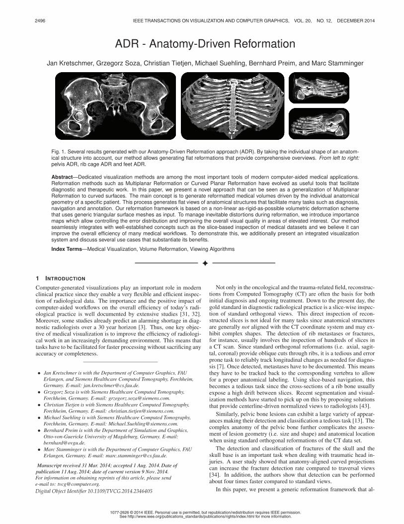
Fig. 7. Reformation results for different weights α for the shearing term ESH . The left shows the original synthetic volume with a sphericalcheckerboard-like pattern, an ADR surface (blue) and the offset surfaces (green and red). The ADR surface was generated by clipping thesurface of a sphere with a cube. Reformation with 0 << α results in a good preservation of angles, but the volume of the upper/lower regions isdecreased/increased which means rigidity is not preserved (1). This is equivalent to parameterizing the surrounding of the ADR surface along thenormals. Removing the weight of the shearing energy (i.e. 0 α) results in a high intra-layer-rigidity but increases shearing (3). Intermediate valuesfor α allow for a reasonable trade-off between intra-layer-rigidity and angular preservation. Setting α = 0.1 usually leads to reasonable results (2).
but intra-layer-rigidity decreases. Figure 7 shows the effect of differ-ent values for α when reformatting a synthetic volume with a cleanspherical checker board parameterization.
Since we assume the layer offset in world space to be constant,as described in Section 4.3.1, Eα does not account for the distancebetween the reformatted layers, but operates on 2D offsets. This meansthe vertex ranges v′i=0...n−1 and v′i=2n...3n−1, that correspond to thepositive and negative layer of the solution, need to be displaced aftersolving by (0,0,d) and (0,0,−d) to span a volumetric slab.
Since the geometry now varies for the different layers, a slight mod-ification to the sampling strategy (see Section 4.2.4) and the mappingbetween ADR space and world space is required. Before computingbarycentric coordinates for the current triangle, it needs to be inter-polated since it is now dependent on the z position in the ADR image.This interpolation can be carried out with linear blending. The triangleat a certain height in the layered ADR stack is thus defined as follows
T (z) = u(v′a−n,v′b−n,v
′c−n)+ v(v′a,v
′b,v
′c)+w(v′a+n,v
′b+n,v
′c+n),
z ∈ [0,2d]
(u,v,w) =
(1− z
d ,zd ,0) 0 < z < d
(0,1− z−dd , z−d
d ) d < z < 2d(9)
where (v′a−n,v′b−n,v′c−n), (v′a,v′b,v
′c) and (v′a+n,v′b+n,v
′c+n) are the
instances of a triangle in the negative, center and positive ADR layersrespectively. Since triangles may now span different pixels dependingon z, we merge the axis-aligned bounding boxes of a triangle in alllayers when enlisting them for sampling as described in Section 4.2.4.
5 IMPORTANCE MAPS FOR ANATOMY-DRIVEN REFORMATION
As laid out in Sections 4.2 and 4.3 the reformation process (surface-based or volumetric) introduces inevitable distortions if the ADR sur-face is not coincidentally developable. Since usually certain parts ofthe ADR surface run through areas of higher interest than others, it isdesirable to account for this during reformation. For this, we introduceimportance maps to control the distribution of the error during refor-mation. The idea is to reduce the error in areas of high importance byadmitting higher distortions in areas of low importance.
To represent importance maps, we allow the vertices of the ADRlayers to be annotated with an additional weight wi that corresponds tothe importance of the area surrounding to the vertex. This can be donemanually by annotating an ADR template mesh beforehand, or inter-actively by reassigning (i.e. painting) weights in the reformatted viewand restarting the reformation process. In applications like bone refor-mations based on CT images, approximate bone masks can easily begenerated automatically by thresholding and post-processing the inputimage. These masks can directly be used to assign importance weightsto the vertices of an ADR surface to distortions at bone regions.
0.1
1
0
1.5
importance
error
Fig. 8. Two reformations based on the same ADR surface with ho-mogeneous importance (left) and an importance map that emphasizesribs (right). The importance map in the right reformation allows a higherdistortion in the area of the sternum and the cartilage connecting it tothe ribs. This results in an overall reduction of the unweighted error inarea of the ribs (bottom row). The average weighted error is 7.40% inthe constant importance reformation and 6.49% in the importance-drivenreformation which corresponds to an error reduction of ≈ 12%. The uni-form error of the high-importance area drops from 7.90% to 5.69% whichcorresponds to an error reduction of ≈ 28% in that area (see Table 1).
To incorporate importance maps, we weight every term in the sumof Equation 3 by the importance of the respective half edge w(i, j)which we take as the average of its end vertex weights w(i, j) =
0.5 · (wi + w j). The final system of equations for the global phasethat includes shearing and importance energy is thus defined as
∑j∈V (i)
w(i, j)(cot(Θi, j)+ cot(Θ j,i))(v′i −v′j)+Ai
= ∑j∈V (i)
w(i, j)(cot(Θi, j)Rt(i, j) + cot(Θ j,i)Rt( j,i))(v0i −v0
j)+Bi
∀i = 0 . . .3n−1
(10)
Here Ai and Bi originate from the shearing term and connect the layers.

2502 IEEE TRANSACTIONS ON VISUALIZATION AND COMPUTER GRAPHICS, VOL. 20, NO. 12, DECEMBER 2014
(Ai,Bi) =
(v′i −v′n+i,−o−i ) i < n(2v′i −v′i−n −v′i+n,o
−i−n +o+i−n) n < i < 2n
(v′i −v′i−n,−o+i−2n) 2n < i < 3n(11)
The left hand side of Equation 10 is static and the corresponding linearsystem is sparse and symmetric. This means it can be factored onceper reformation and can be reused during iterations. The right handside has to be recomputed after each iteration since the rotations Rtdepend on the geometry of the current solution.
6 RESULTS
The versatility of our approach allows for the creation of reformationsfor a large variety of anatomical structures. Figure 9 shows severalanatomical structures with the corresponding ADR surface and the fi-nal reformation results. It features reformations for feet, a pelvis, askull and a rib cage. To place the ADR surfaces into anatomical struc-tures, we initialize and fit a morphable statistical model similar to Seimet al. [38]. We defined the ADR surface in the coordinate system of themean shape of the statistical model and deformed the surface duringmodel fitting using standard linear vertex skinning.
The use of the as-rigid-as-possible deformation framework resultsin low distortions (i.e. deviations from local rigidity) for reformattedvolumes. To quantify the error of a reformation, we take the relativeerrors Error(i, j) of all individual edges and compute the average overthe whole mesh
Error(i, j) =abs(‖v′i −v′j‖−‖vi −v j‖)
‖vi −v j‖
Error =∑(i, j)∈HE w(i, j)Error(i, j)
∑(i, j)∈HE w(i, j).
(12)
By weighting edge errors according to the importance weights of thecorresponding edge w(i, j) as proposed in Equation 12, we get a total er-ror that penalizes distortions in important areas and allows for higherdistortions in unimportant areas. Setting w(i, j) = 1 when computingthe error gives an unbiased error. Figure 8 shows that by supplying im-portance maps, the average error of a reformation can be significantlyreduced. In the example, an error reduction of ≈ 12% is achievedand the errors in the spinal area and the rib area are visibly pushed tothe boundary regions of the reformation. An error of 10% means thatwhen measuring lengths of 4 cm in the reformatted volume, the actuallength in the curved world space setting is 4 mm off on average. Sincewe chose the reformation thickness to enclose the bone structures, theoffset layers are mostly situated in surrounding soft tissue. For this, weset the importance weights based on the center layer only and copiedthem to the corresponding vertices in the offset layers, since otherwisethese layers would receive low importance and higher error. This ishowever due to our application and not a general restriction.
Noticeable errors occur when distortions simply cannot be avoidedentirely during flattening. This behavior is visible in the vicinity ofthe upper spine in Figure 8 (right, center). Table 1 lists error totalsfor the examples presented in Figure 9 and timings for the whole ref-ormation process. It shows that in general the error is low and thatimportance maps help to significantly reduce distortions during refor-mation. We list the errors for constant weights and for automaticallyderived bone importance weights (see Section 5) averaged over thewhole mesh. Here, bone regions were assigned importance weight 1.0and non bone regions were assigned 0.1. In addition, we computedseparate non-weighted error averages over the none bone regions (−)and the bone regions (+). Table 1 shows how importance maps al-low to distribute the error from important regions to unimportant ones.For all examples except the skull, the total weighted error was reducedby importance maps this is because the entire ADR surface is situatedinside of the bone and thus all edges receive the same weight. For im-portance driven reformations, the uniform error measure, drops in (+)at the expense of higher errors in (−). Since our ADR surfaces are in
Table 1. Errors and timings for the reformations shown in Figure 9.Based on bone masks, all ADR surfaces were split in none bone (−)and bone regions (+). The average error for the whole mesh wascomputed on reformations with constant importance maps (Etotal
const ) andimage-based importance maps (Etotal
weighted ). In the latter case, the impor-tance weight was set to 0.1 for none bone and to 1.0 for bone regions.For both settings (constant importance and varying importance) we ad-ditionally computed errors with constant weights for both regions (i.e.E−
const and E+const ). The error of the skull reformation does not decrease
since the entire ADR surface is inside the skull bone (− is empty). Thehigh error for the skull reformation is due to its sphere-like geometry re-sulting in higher distortions for flat embeddings. 100 ARAP iterationswere performed for each dataset. The total reformation time Ttotal andthe times for optimization T opt and resampling T sampl are listed sepa-rately (taken on an Intel Core i7 with 4 cores @2.30 GHz and 8GB RAM).
Dataset Etotalconst (%) Etotal
weighted (%) Ttotal (s)(# Vertices) E−
const E+const E−
const E+const T opt T sampl
Feet 3.19 1.55 7.50(1489) 3.62 2.51 4.68 1.01 4.03 3.467Pelvis 3.93 3.16 14.54(1977) 4.21 3.76 6.40 2.89 5.85 8.69Head 11.07 11.07 15.07(1182) 0 11.07 0 11.07 4.72 10.35Rib Cage 7.40 6.49 11.76(1568) 6.86 7.90 11.40 5.69 4.10 7.66
Fig. 10. Different projections of an alternative ADR for a pelvic bone(compare to Figure 9 that includes the sacrum). Left: no projection.Center: mean intensity projection. Right: maximum intensity projection.Intensity windowing functions were adjusted for consistent brightness.
general well adjusted to the anatomical geometry, the bone regions areusually larger than the non bone regions. This explains, why the totalerrors are more similar to the error of the bone regions than to the errorof the non bone regions.
For most anatomical structures, multiple possibilities exist for theshape of a reasonable ADR surface. When reformatting a pelvic bonefor instance, the sacrum might not be of interest or when examining afracture, a reformation of the left or the right side of the pelvis mightbe sufficient. Figure 10 shows an alternative reformation of a pelviswith an increased focus on the ilium and the pubis and that detachesthe pelvis at the sacrum rather than at the pubis (compare Figure 9).
7 APPLICATIONS FOR ANATOMY-DRIVEN REFORMATIONS
For an efficient use of Anatomy-Driven Reformations, it is crucial toembed the reformatted volume into an adequate medical visualizationenvironment. In this section, we will first discuss several use-casesthat in large parts motivated the development of the presented method.Based on these applications, we will then lay out a proposal for a ref-ormation platform designed to speed up the corresponding diagnosticand navigational tasks.
7.1 Clinical Use-Cases
Upon the detection of malignant primary tumors, it is usually manda-tory for radiologists to examine the skeleton of a patient for secondarymetastases [7]. This is a time-consuming task that has to be performedin regular intervals. Similarly, the presence of trauma injuries requiresa thorough inspection of the respective affected structure.
2503KRETSCHMER ET AL.: ADR - ANATOMY-DRIVEN REFORMATION
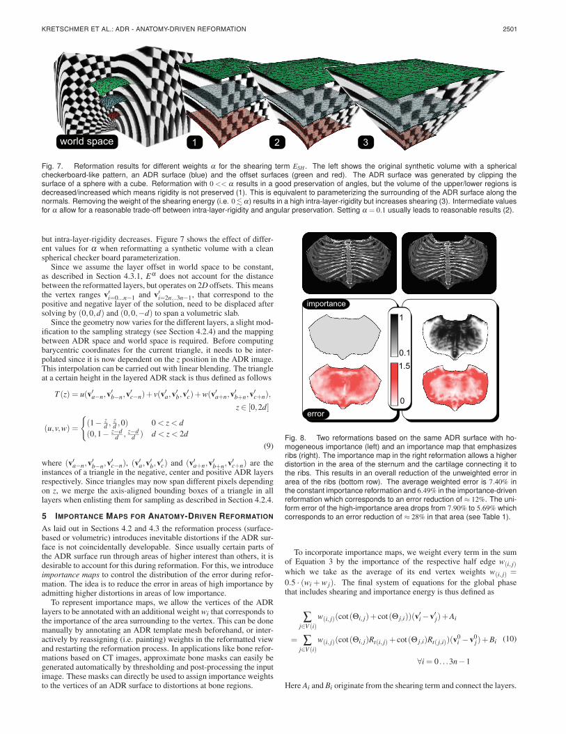
Fig. 9. Several examples for volumetric anatomy-driven bone reformations, where each column is associated with one anatomical structure. Thetop image of each column shows a volume rendering of the anatomical structure in its original shape and context. The center shows a slice fromthe reformatted volume. The bottom shows several renderings of the reformatted volumes that illustrate the normalizing character of our method.
Rib Bone Lesions In case of pathologies in the rib cage, clinicaldocumentation usually requires findings to be assigned to the corre-sponding anatomical rib number (T1-T12). When working in standardorthogonal views, this can be a tedious and error prone task, sinceany detection in a rib needs to be tracked back to the correspondingvertebra. After this, the spine needs to be examined to determine thevertebra number. The same task has to be performed in the presenceof rib fractures.
Pelvic Bone Lesions As in the rib bone scenario, the assessmentof metastases in the pelvic bone is generally aggravated by its curvedgeometry. Depending on the type and progression of a tumor, it can beenclosed entirely by the bone making its geometry depending on thecurvature of the Pelvis.
Skull fractures The detection and assessment of skull fracturesis an important task in trauma imaging since they can lead to severecomplications like cerebrospinal fluid leakage or delayed complica-tions even if no instant hematoma is present [34]. Here, the goal isto detect fractures and to scan their surroundings for abnormalities.Planar cuts do not allow to capture larger regions of the skull surfacereducing the visibility of clear large-scale crack patterns. This compli-cates the detection of thin fractures which is already inherently errorprone [34]. Moreover, the curved shape of the skull complicates lengthmeasurements which are helpful in fracture classification.
For the tasks listed above, ADRs are particularly well suited sincethey enable an inspection of a whole anatomical structure in signifi-cantly fewer 2D images as compared to standard slicing. This is be-cause the thickness of an ADR (and thus the number of slices to beinvestigated) is determined by the thickness of the structure under in-spection and not by the extents of its axis-aligned bounds in voxelcoordinates. In case of the rib cage reformation shown in Figure 9, for
instance, the structure covers ≈ 350mm in height which correspondsto 700 axial slices for the present voxel spacing of ∆x,= ∆y = ∆z =0.5mm. The ADR volume we present, in contrast, has a thickness of≈ 100mm. When using the same voxel spacing as in the original imagethe reformation has 200 slices. To avoid sampling artifacts we usuallyslightly oversample the original image. Even though the individualslices contain more voxels (their resolution can be derived from thevoxels coverd by the ADR surface in world space) the overall amountof image data to be inspected and thus the time needed for examinationare reduced since unimportant areas of the volume are not reformatted.
The condensed anatomical information of ADR images additionallyallows users to exploit symmetries that are common in many anatomi-cal structures. This helps to increase the sensitivity for anomalies thatmight be pathological (see ribs and pelvis in Figure 11). Morover,ADRs facilitate annotation tasks like the determination of the anatom-ical label for a rib, or a vertebra as well as measurement tasks insidean anatomical structure.
7.2 Embedding Anatomy-Driven Reformations
To alleviate the tasks listed in the previous Section, we propose an inte-grated visualization framework enhanced by ADR views. Our frame-work aims to allow radiologists to detect and assess anomalies fasterwhile reducing the risk of missing important pathologies.
The most widely practiced way to explore medical datasets is to in-spect slices from standard orthogonal viewing directions (axial, coro-nal, sagittal) since these provide a genuinely unaltered view of theoriginal reconstruction. For this reason, our overall concept is touse the ADR volume as an additional view for navigation and a fastoverview of the structure of interest. This means we do not proposeto replace original reconstructions by the ADR view, but to combine

2504 IEEE TRANSACTIONS ON VISUALIZATION AND COMPUTER GRAPHICS, VOL. 20, NO. 12, DECEMBER 2014
Fig. 11. Three example applications for ADR; Left to right: a rib cage with tumors, a pelvic bone with tumors and a potential skull fracture. Theupper row shows orthogonal Reformations (axial, sagittal and coronal) and the lower row shows the center slice of the ADR volume. The lesionsmarked by solid boxes are shown in both reformations, whereas the dotted frames indicate additional pathologies instantly visible in the ADR view.Compared to orthogonal views, the ADR view provides a more condensed overview and it allows for an easier assessment of lesion geometry andlocation with respect to the anatomical structure. In case of the potential skull fracture, neither the standard views, nor the ADR is conclusive. Adetail volume rendering of the inside of the reformatted skull area, however, reveals that the abnormality is in fact an emissary vein. For applications,we propose using a combination of the ADR view (detection,navigation) and original reconstructions (ultimate diagnosis).
the advantages of both: The image fidelity of the original reconstruc-tion and the fast access and aggregated character of the ADR. Basedon this approach, we propose a window layout as depicted in Figure12 which consists of the ADR view, three linked standard views andan additional side view with a context-dependent variety of tools. Forexample, to perform measurements on fractures, a measurement toolcan be provided to draw curves in the ADR view. After transformingthe curve back to world space, very precise length measurements, thatfollow the anatomical geometry can be performed. As an additionaltool, curves drawn in the ADR view could also be used to create CPRvisualizations of rib bones or spine regions. The condensed ADR viewallows doing this with fewer interactions and less slicing as comparedto standard views. When inspecting ADRs, it might furthermore beadvantageous to integrate information over a certain depth, similar asproposed in [34] or in [9]. All common projection algorithms such asMaximum-, Minimum-, and Mean Intensity Projections can be com-bined with our reformation as illustrated in Figure 10.
ADR VIEW
LINKED VIEWaxial
LINKED VIEWcoronal
LINKED VIEWsagittal
MULTI VIEW
Fig. 12. Our proposal for embedding ADR in medical applications. TheADR VIEW shows the reformatted volume, supports slicing and differ-ent projections and acts as an anatomical atlas. The current viewingposition and the zoom of the LINKED VIEWs is synchronized with theADR view. The MULTI VIEW panel shows a contextual volume render-ing which can be replaced by dynamic context-dependent tools.
8 CONCLUSION
We present ADR as a novel deformation-based approach to medicalimage reformation. The anatomy-awareness of ADR helps to facilitatemany time-consuming tasks like diagnosis, navigation or annotation
and integrates seamlessly with existing visualization concepts. By ex-plicitly minimizing deviations from local rigidity during deformation,our reformations expose very low distortions which we confirm in adiverse set of examples. To provide further control over the distribu-tion of errors, we introduce a weighting scheme that allows increasingthe faithfulness of reformations in areas of elevated importance. Todemonstrate the usefulness of our method, we present several clinicalapplications and tasks that can increase their efficiency by introducingADRs.
ADR is based on surface meshes that are usually placed in the cen-ter of the anatomical structure subject to investigation. This meansthat the quality of the final reformation depends on the precision andreliability of that surface. Since, however, our volumetric approachparameterizes a thick surrounding of the ADR surface, it is less sen-sitive to small errors of the input data than current cut surface-basedmethods. One issue is that for some shapes of ADR surfaces, the off-set surfaces may expose local or global self-intersections. In Section4.3.1 we propose a strategy that usually removes local artifacts but forvery thick and curved reformations global self-intersections cannot becompletely avoided. In the variety of examples we presented in thispaper, however, self-intersections were not an issue. Moreover, evenif they occur, the mapping between world space and ADR space sim-ply looses bijectivity but the approach does not break.
A limitation of the presented method is that it currently only explic-itly models and minimizes the intra-layer distortion for 3 discrete lay-ers. For current applications, however, three layers are sufficient sincethe corresponding anatomical structures can be parameterized by thesurrounding of a surface. One way to extend the presented methodwould be to allow an arbitrary number of layers.
Current applications (see Section 7.1) focus on bone structures. Weare, however, currently exploring different applications for our methodlike colon unfolding or the reformation of organs like kidneys or theheart. A restriction of our reformation approach, relevant in this re-spect is, that the structure the ADR surface is limited to open surfaces.This restriction is however necessary for the existence of a continu-ous flat embedding of a structure and does not pose problems for theproposed application to bones.
Our approach has shown promising results for oncological andtrauma-related bone reading tasks and we see great potential for otherapplications like whole-body atlases or side-by-side comparisons. Weare currently exploring semi-automatic variations of our method forad hoc ADRs based on user sketches. Future work will focus on fur-ther developing and quantitatively evaluating our prototype applicationwith respect to the efficiency gain for specific clinical tasks.

2505KRETSCHMER ET AL.: ADR - ANATOMY-DRIVEN REFORMATION
REFERENCES
[1] T. Auzinger, G. Mistelbauer, I. Baclija, R. Schernthaner, A. Kochl,M. Wimmer, E. Groller, and S. Bruckner. Vessel visualization usingcurved surface reformation. IEEE Transactions on Visualization andComputer Graphics, 19(12):2858–2867, 2013.
[2] A. V. Bartrolı, R. Wegenkittl, A. Konig, and E. Groller. Nonlinear virtualcolon unfolding. In Proc. of IEEE Visualization, pages 411–420, 2001.
[3] M. Bhargavan, J. H. Sunshine, and B. Schepps. Too few radiologists?American Journal of Roentgenology, 178(5):1075–1082, 2002.
[4] G. Chintalapani, L. M. Ellingsen, O. Sadowsky, J. L. Prince, and R. H.Taylor. Statistical atlases of bone anatomy: construction, iterative im-provement and validation. In Medical Image Computing and Computer-Assisted Intervention (MICCAI), pages 499–506. Springer, 2007.
[5] T. F. Cootes, G. J. Edwards, C. J. Taylor, et al. Active appearance mod-els. IEEE Transactions on pattern analysis and machine intelligence,23(6):681–685, 2001.
[6] T. F. Cootes and C. J. Taylor. Active shape modelssmart snakes. InBMVC92, pages 266–275. 1992.
[7] M. De Maeseneer, J. De Mey, L. Lenchik, H. Everaert, and M. Osteaux.Helical ct of rib lesions: a pattern-based approach. American Journal ofRoentgenology, 182(1):173–179, 2004.
[8] T. Delame, C. Roudet, and D. Faudot. From a medial surface to a mesh.In Computer Graphics Forum, volume 31, pages 1637–1646, 2012.
[9] V. Dicken, B. Wein, H. Schubert, J.-M. Kuhnigk, S. Kra, and H.-O. Peit-gen. Novel projection views for simplified reading of thorax CT scanswith multiple pulmonary nodules. Proc. of CARS, 1256(0):59 – 64, 2003.
[10] A. du Bois dAische, M. De Craene, S. Haker, N. Weisenfeld, C. Tempany,B. Macq, and S. K. Warfield. Improved non-rigid registration of prostateMRI. In Medical Image Computing and Computer-Assisted Intervention(MICCAI), pages 845–852. Springer, 2004.
[11] N. Faraj, J.-M. Thiery, I. Bloch, N. Varsier, J. Wiart, and T. Boubekeur.Robust and scalable interactive freeform modeling of high definitionmedical images. In Mesh Processing in Medical Image Analysis 2012,pages 1–11. Springer, 2012.
[12] M. S. Floater. Parametrization and smooth approximation of surface tri-angulations. Computer aided geometric design, 14(3):231–250, 1997.
[13] G. Girish, K. Finlay, D. Fessell, D. Pai, Q. Dong, and D. Jamadar. Imag-ing review of skeletal tumors of the pelvis malignant tumors and tumormimics. The Scientific World Journal, 2012, 2012.
[14] W. Hong, X. Gu, F. Qiu, M. Jin, and A. Kaufman. Conformal virtualcolon flattening. In Proc. of the 2006 ACM symposium on Solid andphysical modeling, pages 85–93. ACM, 2006.
[15] D. K. Jeong, K. H. Lee, B. H. Kim, K. J. Kim, Y. H. Kim, V. Bajpai,and Y. G. Shin. On-the-fly generation of multiplanar reformation imagesindependent of CT scanner type. Journal of digital imaging, 21(3):306–311, 2008.
[16] W. Kabsch. A solution for the best rotation to relate two sets of vectors.Acta Crystallographica Section A, 32(5):922–923, 1976.
[17] A. Kanitsar, D. Fleischmann, R. Wegenkittl, P. Felkel, and E. Groller.CPR - curved planar reformation. In Proc. of IEEE Visualization, pages37–44, 2002.
[18] A. Kanitsar, R. Wegenkittl, D. Fleischmann, and E. Groller. AdvancedCurved Planar Reformation: Flattening of Vascular Structures. In Proc.of IEEE Visualization, pages 43–50, 2003.
[19] G. A. Lavi. Mapping the coronary arteries on a sphere in CT angiogra-phy. In Medical Imaging 2004, pages 285–293. International Society forOptics and Photonics, 2004.
[20] T.-C. Lee, R. L. Kashyap, and C.-N. Chu. Building skeleton models via3-d medial surface axis thinning algorithms. CVGIP: Graphical Modelsand Image Processing, 56(6):462–478, 1994.
[21] Z. Levi and D. Levin. Shape deformation via interior RBF. IEEE Trans-actions on Visualization and Computer Graphics, 20(7):1062–1075, July2014.
[22] B. Levy, S. Petitjean, N. Ray, and J. Maillot. Least squares conformalmaps for automatic texture atlas generation. In ACM Transactions onGraphics (TOG), volume 21, pages 362–371. ACM, 2002.
[23] L. Liu, L. Zhang, Y. Xu, C. Gotsman, and S. J. Gortler. A local/globalapproach to mesh parameterization. In Computer Graphics Forum, vol-ume 27, pages 1495–1504, 2008.
[24] S. Makram-Ebeid and O. Somphone. Non-rigid image registration usinga hierarchical partition of unity finite element method. In Proc. of IEEEComputer Vision, pages 1–8. IEEE, 2007.
[25] L. S. Medina. Three-dimensional CT maximum intensity projections ofthe calvaria: a new approach for diagnosis of craniosynostosis and frac-tures. American journal of neuroradiology, 21(10):1951–1954, 2000.
[26] G. Mistelbauer, A. Varchola, H. Bouzari, J. Starinsky, A. Kochl, R. Sch-ernthaner, D. Fleischmann, M. E. Groller, and M. Sramek. Centerlinereformations of complex vascular structures. In IEEE PacificVis, pages233–240, 2012.
[27] A. Nealen, T. Igarashi, O. Sorkine, and M. Alexa. Laplacian mesh opti-mization. In Proc. of GRAPHITE, pages 381–389. ACM, 2006.
[28] D. S. Paik, C. F. Beaulieu, R. B. Jeffrey Jr, C. A. Karadi, and S. Napel.Visualization modes for CT colonography using cylindrical and planarmap projections. Journal of computer assisted tomography, 24(2):179–188, 2000.
[29] D. Pavic and L. Kobbelt. High-resolution volumetric computation of off-set surfaces with feature preservation. In Computer Graphics Forum,volume 27, pages 165–174, 2008.
[30] U. Pinkall and K. Polthier. Computing discrete minimal surfaces and theirconjugates. Experimental mathematics, 2(1):15–36, 1993.
[31] B. Reiner. Automating radiologist workflow, part 2: hands-free naviga-tion. Journal of the American College of Radiology, 5(11):1137–1141,2008.
[32] B. I. Reiner, E. L. Siegel, F. J. Hooper, S. Pomerantz, A. Dahlke, andD. Rallis. Radiologists’ productivity in the interpretation of CT scans:a comparison of pacs with conventional film. American Journal ofRoentgenology, 176(4):861–864, 2001.
[33] C. Rieder, A. Weihusen, C. Schumann, S. Zidowitz, and H.-O. Peitgen.Visual support for interactive post-interventional assessment of radiofre-quency ablation therapy. 29(3):1093–1102, 2010.
[34] H. Ringl, R. E. Schernthaner, G. Schueller, C. Balassy, D. Kienzl,A. Botosaneanu, M. Weber, C. Czerny, S. Hajdu, T. Mang, et al. Theskull unfolded: a cranial CT visualization algorithm for fast and easy de-tection of skull fractures. Radiology, 255(2):553, 2010.
[35] J. R. Rossignac and A. A. Requicha. Offsetting operations in solid mod-elling. Computer Aided Geometric Design, 3(2):129–148, 1986.
[36] L. Saroul, O. Figueiredo, and R.-D. Hersch. Distance preserving flatten-ing of surface sections. IEEE Transactions on Visualization and Com-puter Graphics, 12(1):26–35, Jan 2006.
[37] L. Saroul, S. Gerlach, and R. D. Hersch. Exploring curved anatomicstructures with surface sections. In Proc. of the IEEE Visualization, pages5–12, 2003.
[38] H. Seim, D. Kainmueller, M. Heller, H. Lamecker, S. Zachow, and H.-C.Hege. Automatic segmentation of the pelvic bones from CT data basedon a statistical shape model. In EG Workshop on Visual Computing inBiology and Medicine, pages 93–100, 2008.
[39] A. Shamir. A survey on mesh segmentation techniques. Computer Graph-ics Forum, 27(6):1539–1556, 2008.
[40] O. Sorkine and M. Alexa. As-rigid-as-possible surface modeling. InSymposium on Geometry processing, volume 4, pages 109–116, 2007.
[41] M. Termeer, J. Bescos, M. Breeuwer, A. Vilanova, F. Gerritsen, andE. Groller. Covicad: Comprehensive visualization of coronary arterydisease. IEEE Transactions on Visualization and Computer Graphics,13(6):1632–1639, Nov 2007.
[42] D. Williams, S. Grimm, E. Coto, A. Roudsari, and H. Hatzakis. Volumet-ric curved planar reformation for virtual endoscopy. IEEE Transactionson Visualization and Computer Graphics, 14(1):109–119, Jan 2008.
[43] D. Wu, D. Liu, Z. Puskas, C. Lu, A. Wimmer, C. Tietjen, G. Soza, andS. K. Zhou. A learning based deformable template matching method forautomatic rib centerline extraction and labeling in CT images. In IEEEConference on Computer Vision and Pattern Recognition (CVPR), pages980–987, 2012.
[44] W. Zeng, Y. Zeng, Y. Wang, X. Yin, X. Gu, and D. Samaras. 3d non-rigidsurface matching and registration based on holomorphic differentials. InComputer Vision–ECCV 2008, pages 1–14. Springer, 2008.
[45] S. Zhang, A. Nealen, and D. Metaxas. Skeleton based as-rigid-as-possiblevolume modeling. In Eurographics 2010-Short Papers, pages 21–24,2010.
[46] M. Zollhofer, E. Sert, G. Greiner, and J. Sußmuth. GPU based arap de-formation using volumetric lattices. In Eurographics 2012-Short Papers,pages 85–88. The Eurographics Association, 2012.
[47] G. Zou, J. Hua, and O. Muzik. Non-rigid surface registration usingspherical thin-plate splines. In Medical Image Computing and Computer-Assisted Intervention (MICCAI), pages 367–374. 2007.


![Vortex Cores of Inertial Particlesvis.cs.ucdavis.edu/vis2014papers/TVCG/papers/2535...chines. A number of formal vortex definitions exist in the literature [10, 12, 13, 21], and several](https://img.pdfslide.us/doc/110x75/6119782f702aee4bec3e39cf/vortex-cores-of-inertial-chines-a-number-of-formal-vortex-deinitions-exist.jpg)