Embed Size (px)
Citation preview

Administration
• Fire procedure
• Toilets
• Breaks
• Mobile telephones – please turn off

Agenda
• Technology development
• ECM logic
• Terminology
• Ignition system analysis
• Engine management systems
• Sensor identification and testing
• Closed loop fuelling
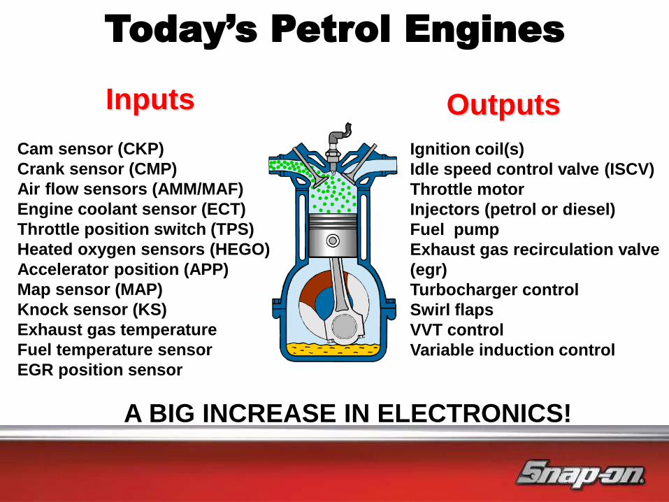
Today’s Petrol Engines
Cam sensor (CKP)
Crank sensor (CMP)
Air flow sensors (AMM/MAF)
Engine coolant sensor (ECT)
Throttle position switch (TPS)
Heated oxygen sensors (HEGO)
Accelerator position (APP)
Map sensor (MAP)
Knock sensor (KS)
Exhaust gas temperature
Fuel temperature sensor
EGR position sensor
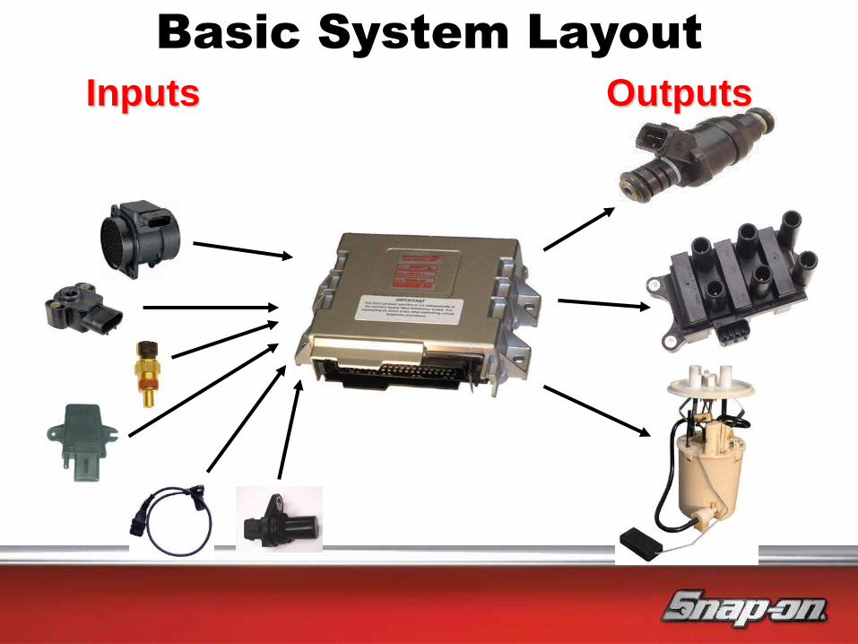
Inputs
Ignition coil(s)
Idle speed control valve (ISCV)
Throttle motor
Injectors (petrol or diesel)
Fuel pump
Exhaust gas recirculation valve
(egr)
Turbocharger control
Swirl flaps
VVT control
Variable induction control
Outputs
A BIG INCREASE IN ELECTRONICS!

Today’s Diesel Engines
Inputs Cam sensor
Crank sensor
Air mass meter
Map sensor
Rail pressure sensor
Throttle position
Fuel temperature
EGT
EGR position
DPFE sensor
Outputs Electronic injectors
EGR valves
Additive systems
Inlet metering valves
Pressure regulator
Swirl flaps
Glow plugs

Petrols and Diesels
All controlled by a computer!
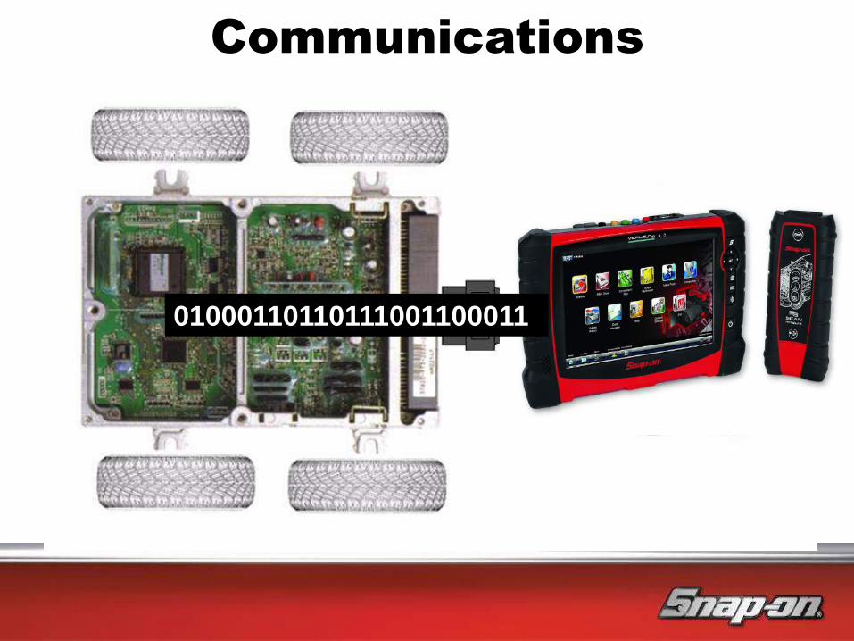
Communications
01000110110111001100011
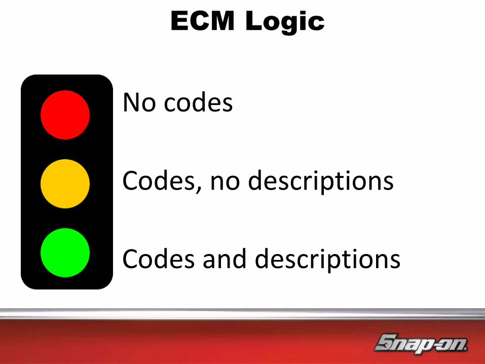
No codes
Codes, no descriptions
Codes and descriptions
ECM Logic
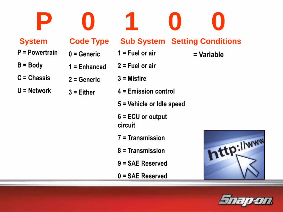
P 0 1 0 0 Setting Conditions System
P = Powertrain
B = Body
C = Chassis
U = Network
Code Type
0 = Generic
1 = Enhanced
2 = Generic
3 = Either
Sub System
1 = Fuel or air
2 = Fuel or air
3 = Misfire
4 = Emission control
5 = Vehicle or Idle speed
6 = ECU or output
circuit
7 = Transmission
8 = Transmission
9 = SAE Reserved
0 = SAE Reserved
= Variable

Electrical
Fundamentals,
Sensors and Testing
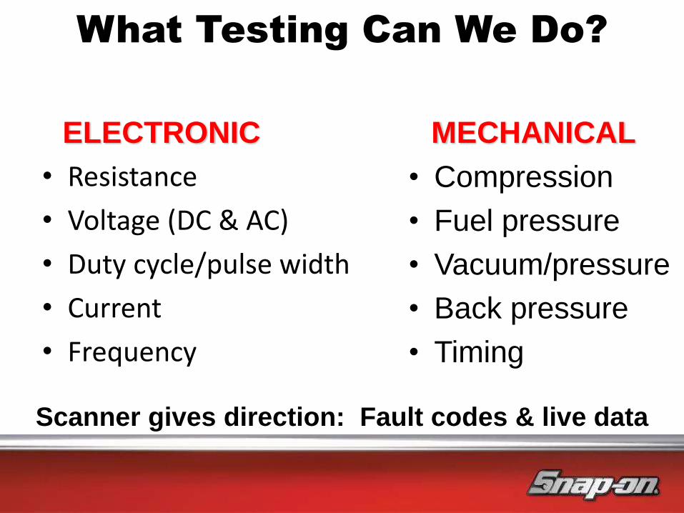
• Resistance
• Voltage (DC & AC)
• Duty cycle/pulse width
• Current
• Frequency
What Testing Can We Do?
• Compression
• Fuel pressure
• Vacuum/pressure
• Back pressure
• Timing
ELECTRONIC MECHANICAL
Scanner gives direction: Fault codes & live data

The physical
pathway for current
flow is called an
electrical circuit
Electrical Fundamentals
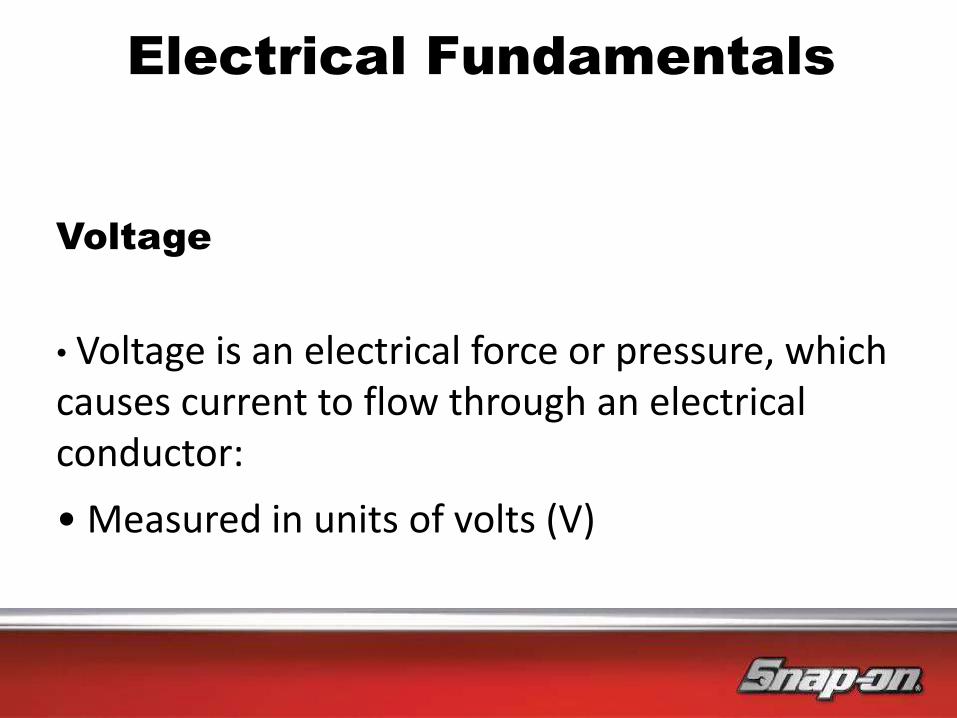
Voltage
• Voltage is an electrical force or pressure, which causes current to flow through an electrical conductor:
• Measured in units of volts (V)
Electrical Fundamentals

Current
• Current is the flow of electrons through a conductor
• Measured in units of amperes or "amps" (A)
Electrical Fundamentals
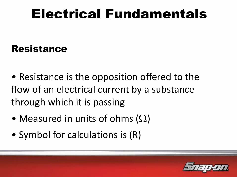
Resistance
• Resistance is the opposition offered to the flow of an electrical current by a substance through which it is passing
• Measured in units of ohms ()
• Symbol for calculations is (R)
Electrical Fundamentals

• Resistance testing requires the component to be taken out of circuit
• Resistance varies with temperature
• Resistance testing is not “live testing” in a normal operating environment
Resistance Is Futile!

• Resistance has limited use
• Use volt drop
• Use current
How Do We Test Circuits?
V
A

Current with a constant voltage = Higher resistance - lower amps Lower resistance - higher amps
Ohms Law
• A relationship exists between the
voltage, current and resistance within
the circuit, and this relationship is
called Ohms Law
• Ohms law states:
– “That one Volt is required to pass one Amp through a one Ohm resistance, providing that the temperature remains constant”
• An easy way to calculate Ohms law,
within a circuit, is to use the diagram
to the side
V
A R X
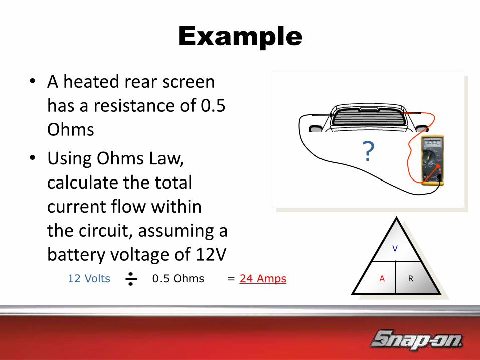
Example
• A heated rear screen has a resistance of 0.5 Ohms
• Using Ohms Law, calculate the total current flow within the circuit, assuming a battery voltage of 12V
V
A R
?
12 Volts 0.5 Ohms = 24 Amps
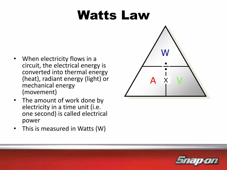
Watts Law
• When electricity flows in a circuit, the electrical energy is converted into thermal energy (heat), radiant energy (light) or mechanical energy (movement)
• The amount of work done by electricity in a time unit (i.e. one second) is called electrical power
• This is measured in Watts (W)
V
A R
W
A V X

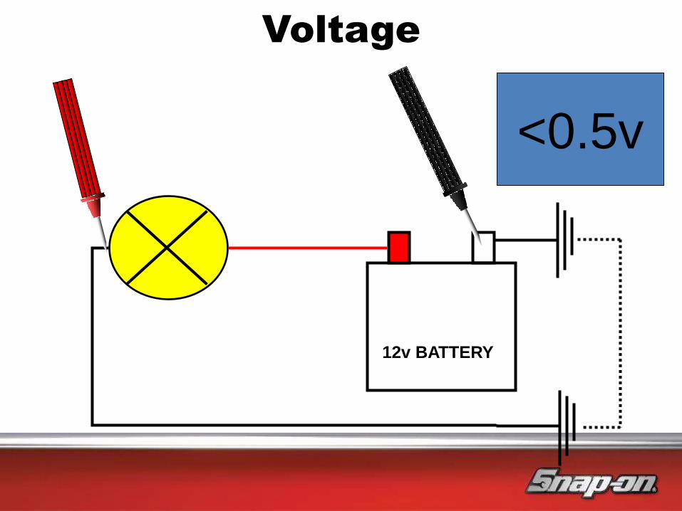
Voltage
12v BATTERY
12v
Voltage
12v BATTERY
<0.5v
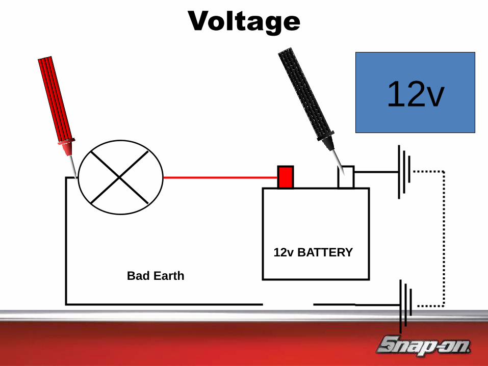
Voltage
12v BATTERY
12v
Bad Earth
0.5v
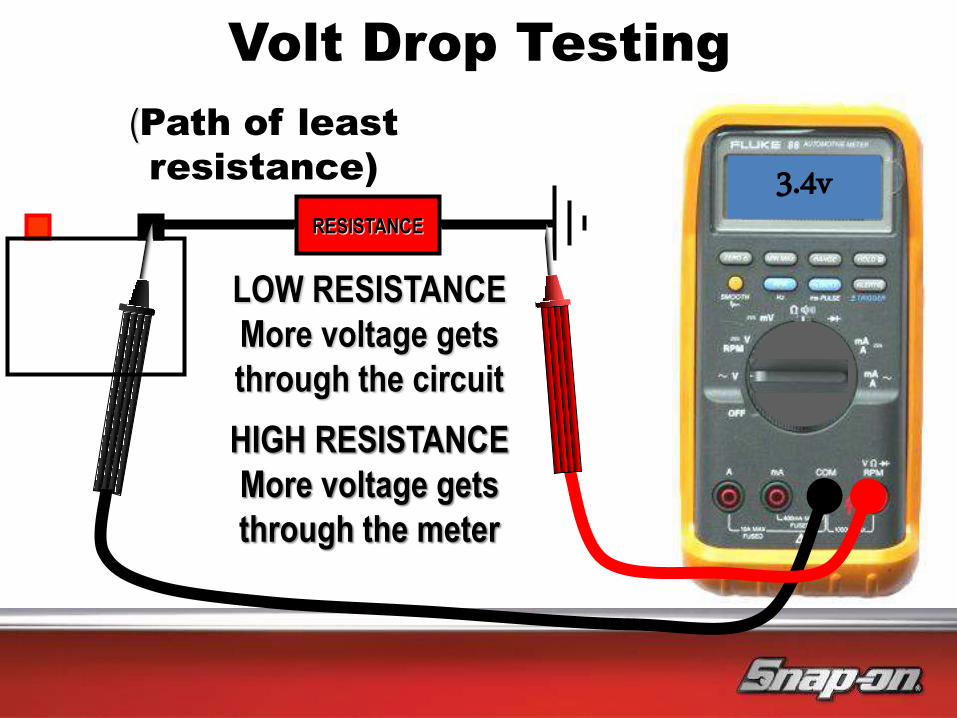
Volt Drop Testing
LOW RESISTANCE
More voltage gets
through the circuit
RESISTANCE
3.4v
HIGH RESISTANCE
More voltage gets
through the meter
(Path of least
resistance)
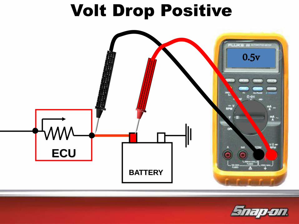
Volt Drop Positive
ECU
BATTERY
0.5v
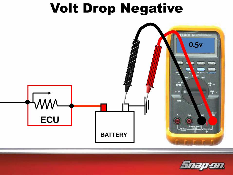
Volt Drop Negative
ECU
BATTERY
0.5v
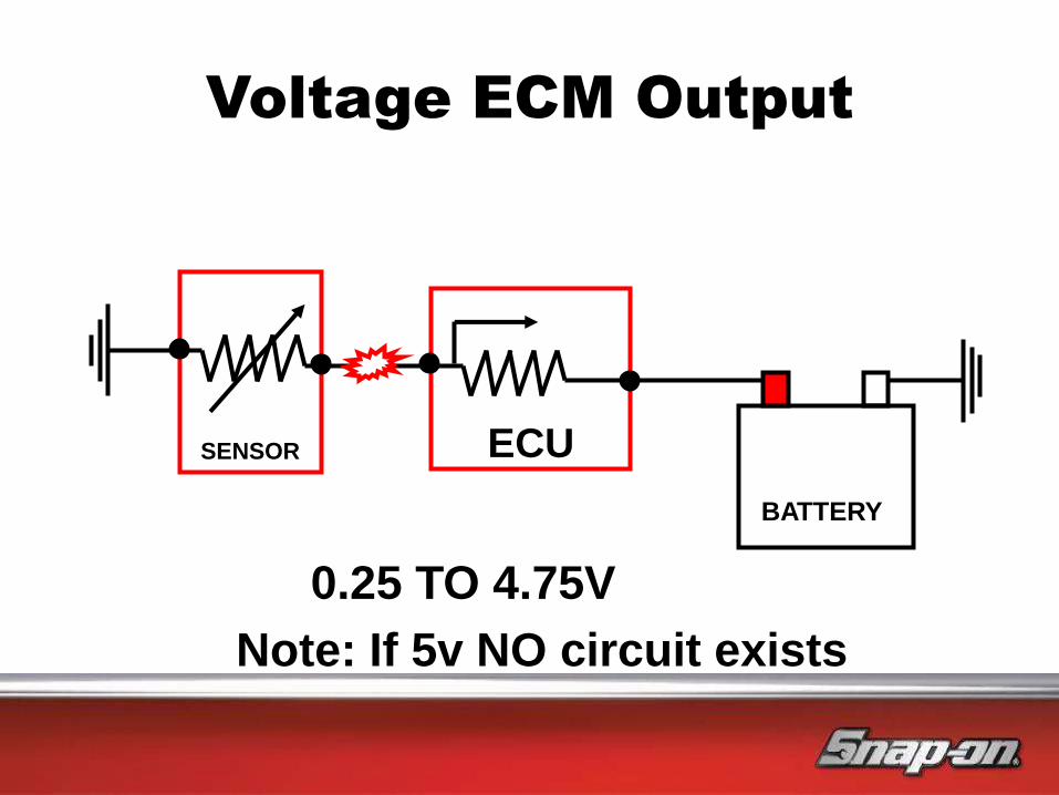
Voltage ECM Output
SENSOR ECU
BATTERY
0.25 TO 4.75V
Note: If 5v NO circuit exists

SENSOR ECU
BATTERY
Typical sensor cicuit
+ve
Measuring Point
Inside ECU
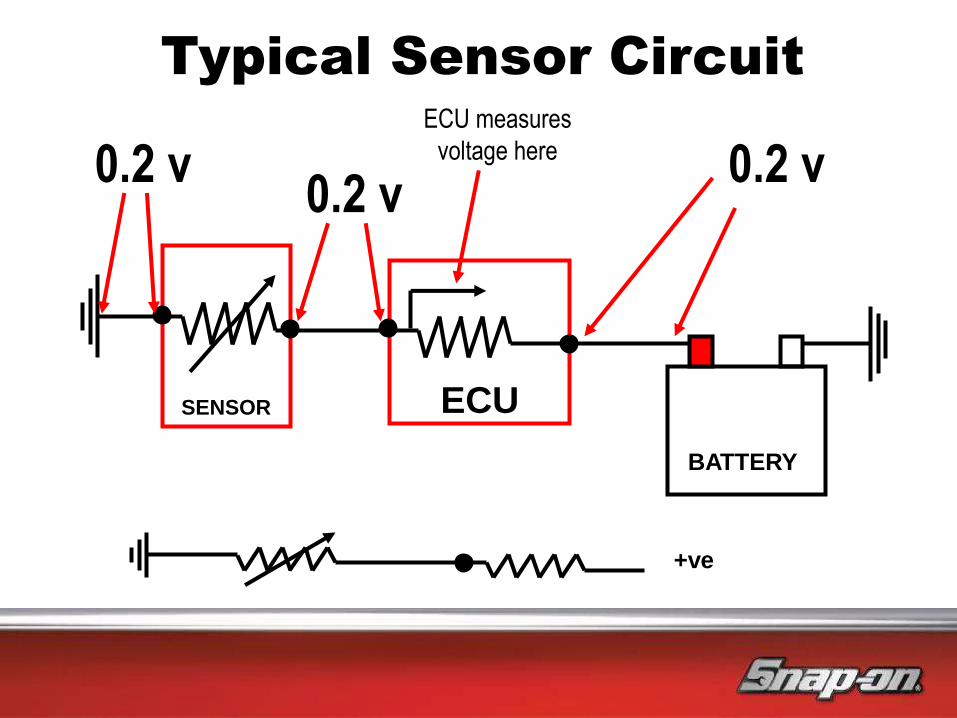
SENSOR ECU
BATTERY
Typical Sensor Circuit
+ve
0.2 v 0.2 v
0.2 v ECU measures
voltage here
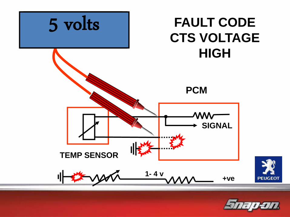
TEMP SENSOR
SIGNAL
PCM
1.5 volts FAULT CODE
CTS VOLTAGE
HIGH
0 volts 5 volts
1- 4 v +ve

Current can tell us:
• There is a circuit…current can only flow if there is a circuit
• How much current is flowing
• What work is being done by the component
Current ramping is an advanced technique used with oscilloscopes
Current Testing

• Analogue (AC wave form output)
• Digital (square wave form output)
• Frequency
• Pulse width (Modulated)
• Duty cycle (Modulated)
Jargon Busting
The ECM uses all of these signals to control and monitor
sensors and actuators
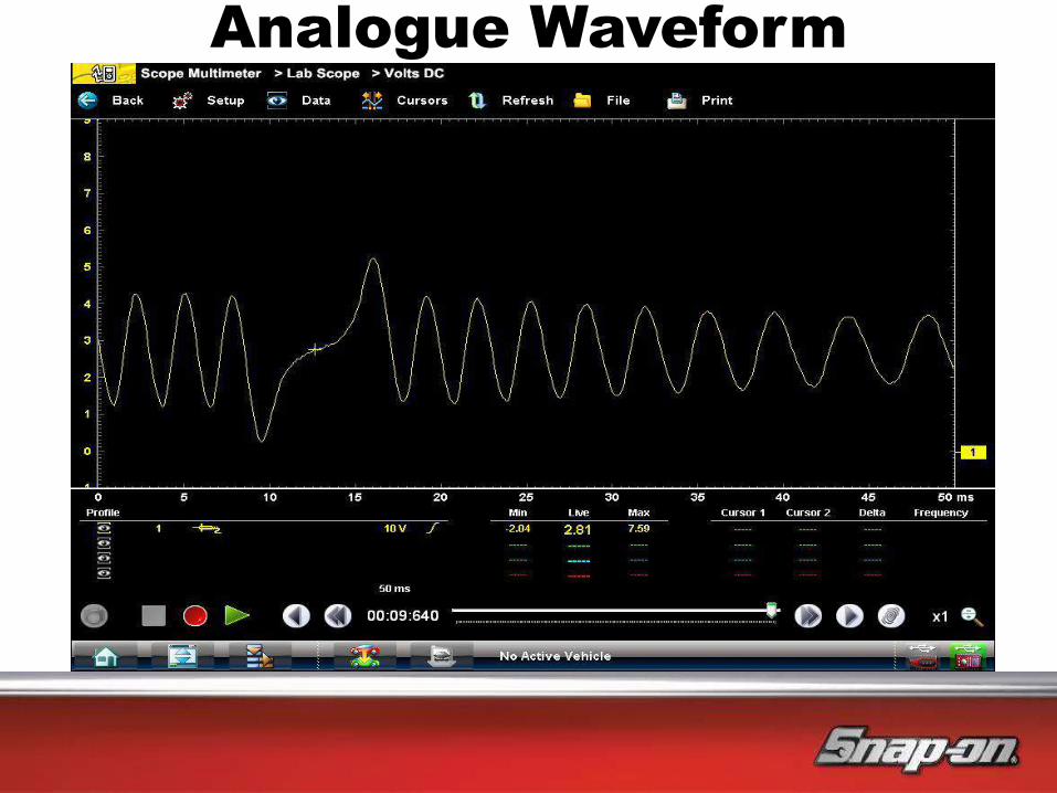
Analogue Waveform

Digital Waveform

Digital Square Waveform
Frequency
1 sec
period
Voltage does not change due to frequency increase
Voltage must peak to input voltage and switch to 0v for ECU to acknowledge an
on/ off signal
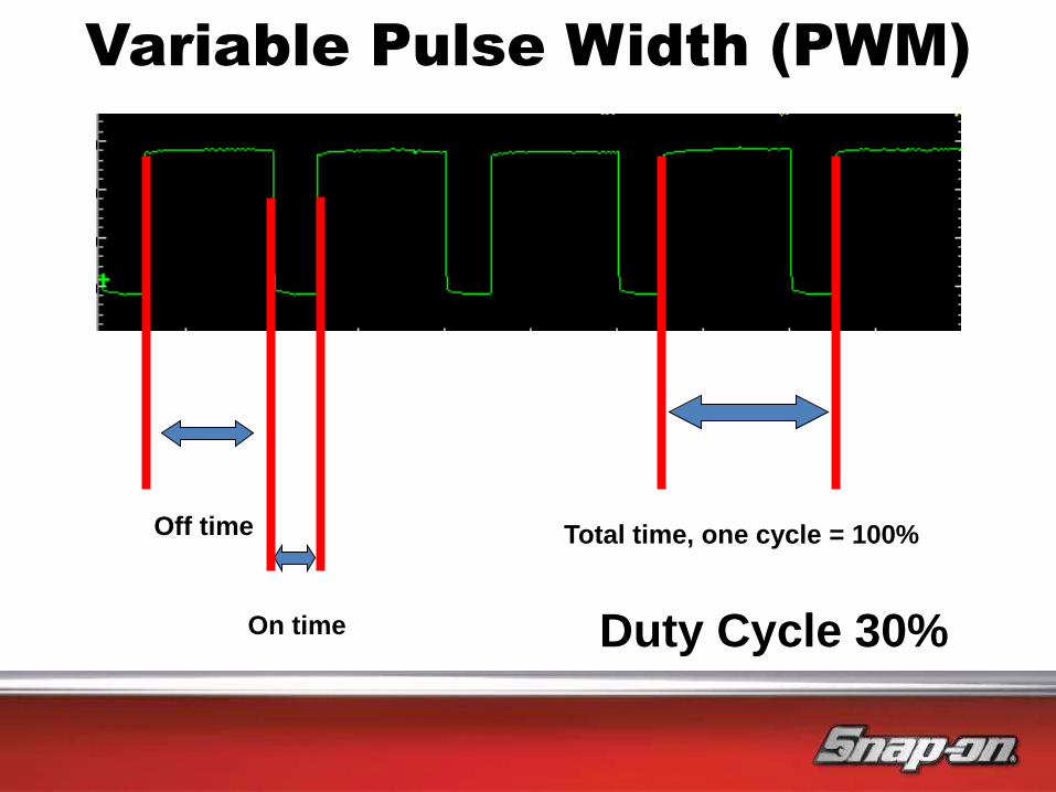
On time
Off time Total time, one cycle = 100%
Variable Pulse Width (PWM)
Duty Cycle 30%
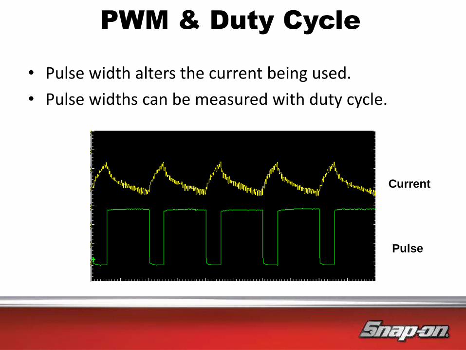
• Pulse width alters the current being used.
• Pulse widths can be measured with duty cycle.
PWM & Duty Cycle
Current
Pulse
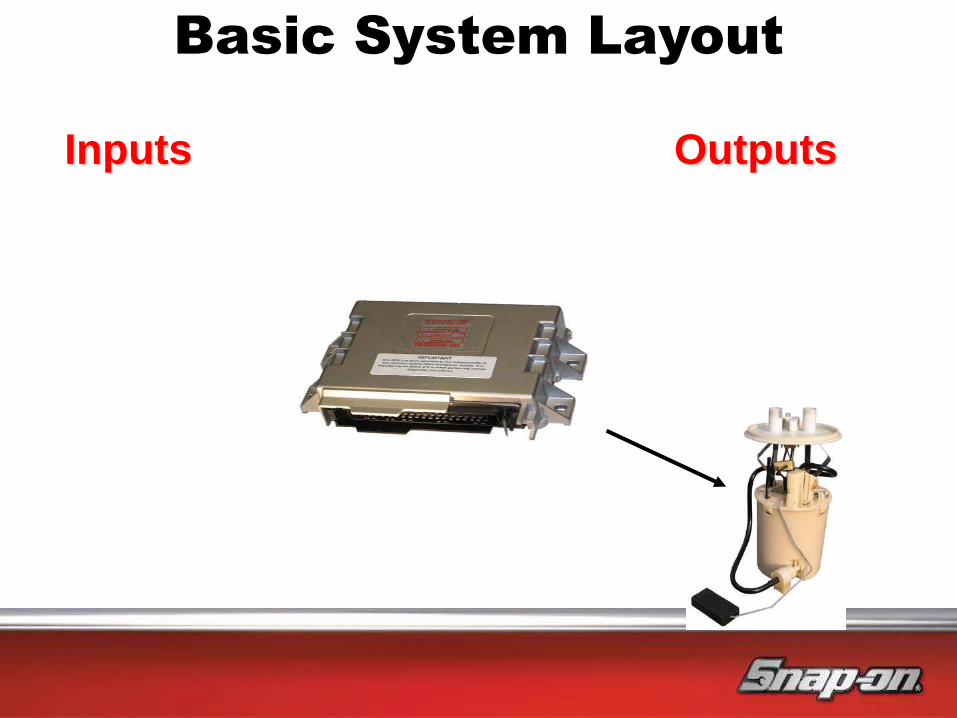
Inputs Outputs
Basic System Layout
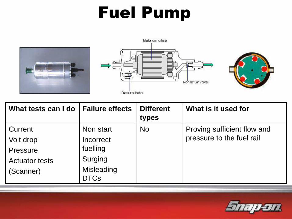
Fuel Pump
What tests can I do Failure effects Different
types
What is it used for
Current
Volt drop
Pressure
Actuator tests
(Scanner)
Non start
Incorrect
fuelling
Surging
Misleading
DTCs
No Proving sufficient flow and
pressure to the fuel rail
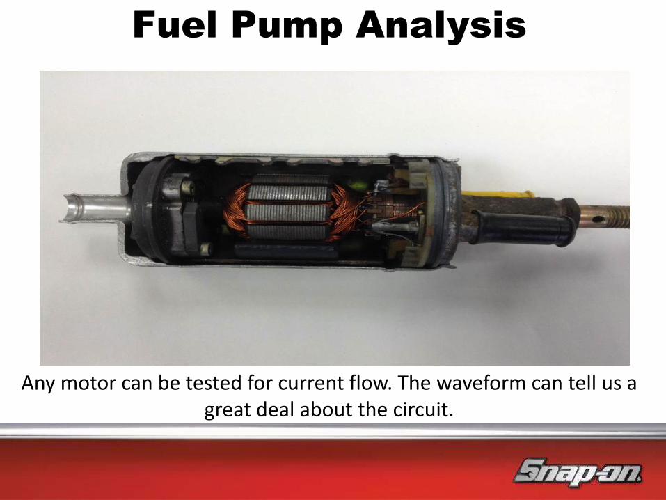
Fuel Pump Analysis
Any motor can be tested for current flow. The waveform can tell us a great deal about the circuit.

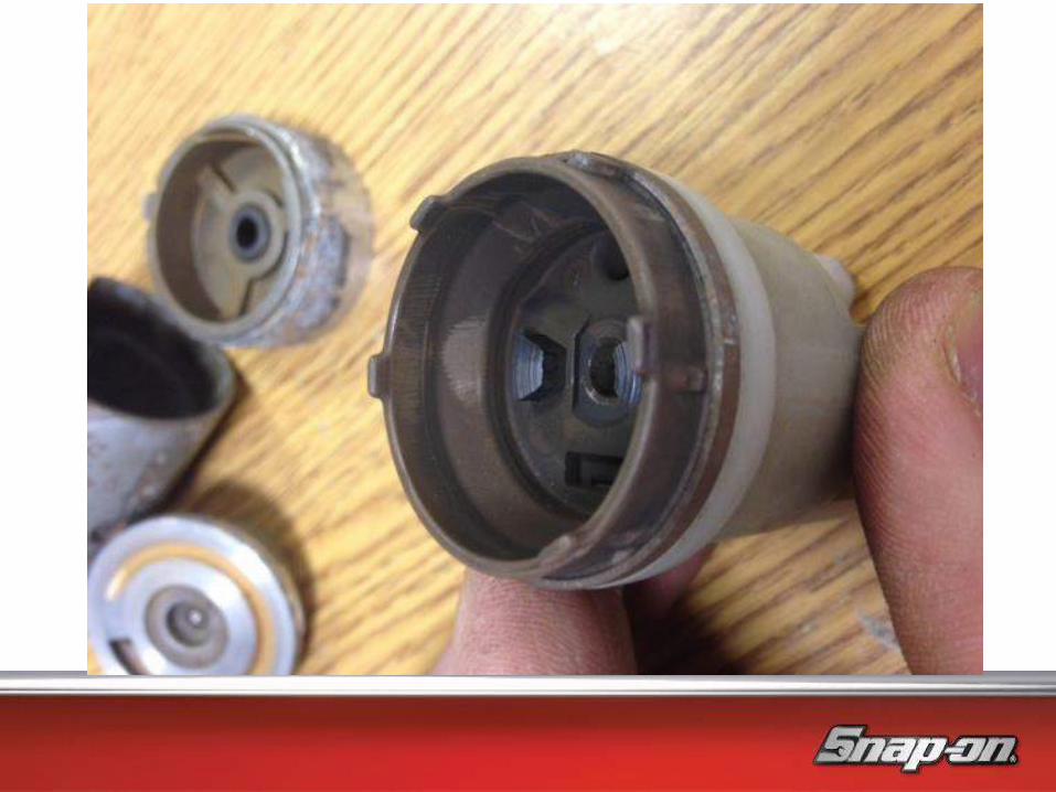

Fuel Pump Analysis
Find a convenient point in the circuit and simply
clamp one of the wires.

Inbuilt Tuition

Fuel Pump Testing
Fuel pump speed analysis
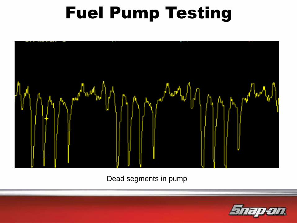
Dead segments in pump
Fuel Pump Testing

Inputs Outputs
Basic System Layout
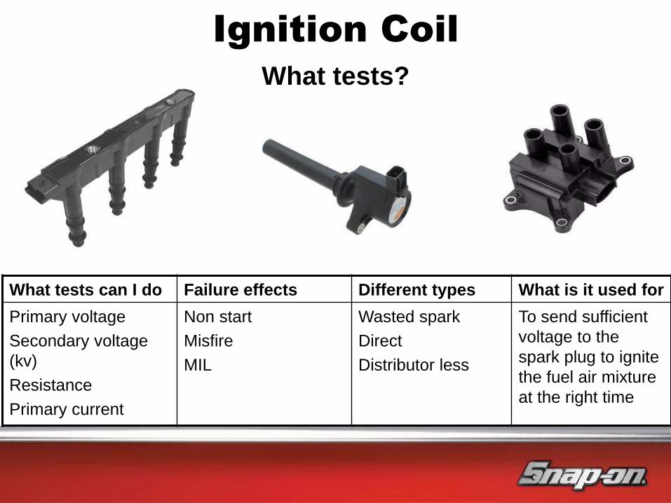
Ignition Coil
What tests can I do Failure effects Different types What is it used for
Primary voltage
Secondary voltage
(kv)
Resistance
Primary current
Non start
Misfire
MIL
Wasted spark
Direct
Distributor less
To send sufficient
voltage to the
spark plug to ignite
the fuel air mixture
at the right time
What tests?
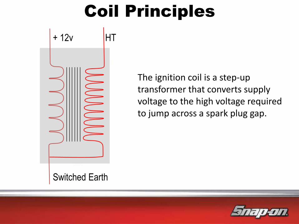
Coil Principles
The ignition coil is a step-up transformer that converts supply voltage to the high voltage required to jump across a spark plug gap.
+ 12v
Switched Earth
HT

Conventional System
Terminal 15
Ignition Supply
Terminal 1
Coil Control
ECU/ Ignition AMP
Removing the points and
condenser
Primary
Secondary
Direct connection to
plug COP System
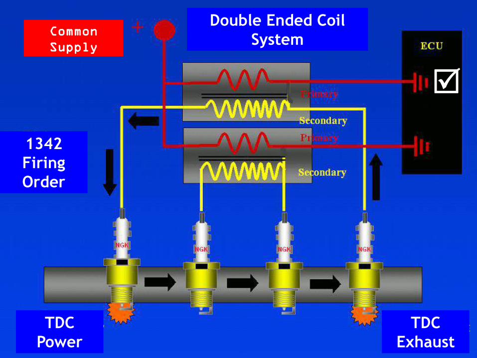
1342
Firing
Order
TDC
Power
TDC
Exhaust
Double Ended Coil
System
Common
Supply

1342
Firing
Order
Double Ended Coil
System
TDC
Power
TDC
Exhaust
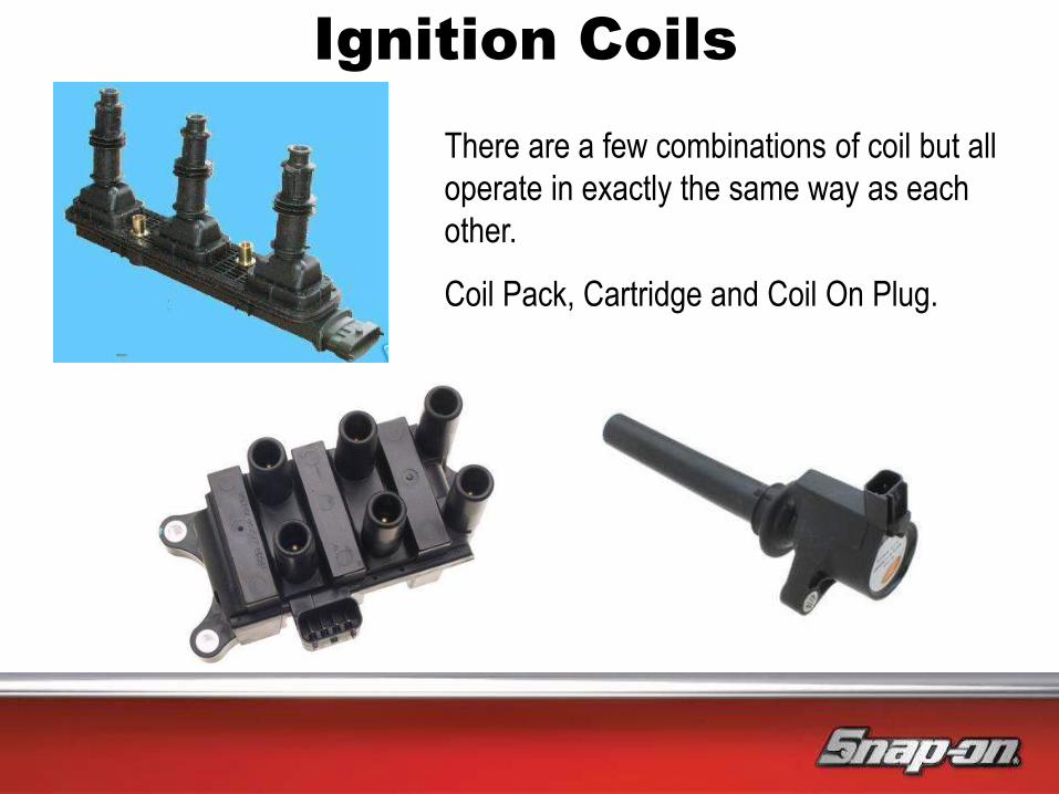
There are a few combinations of coil but all
operate in exactly the same way as each
other.
Coil Pack, Cartridge and Coil On Plug.
Ignition Coils
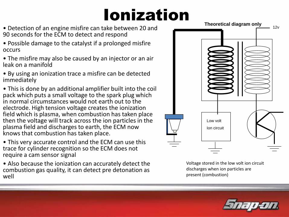
Ionization
• Detection of an engine misfire can take between 20 and 90 seconds for the ECM to detect and respond
• Possible damage to the catalyst if a prolonged misfire occurs
• The misfire may also be caused by an injector or an air leak on a manifold
• By using an ionization trace a misfire can be detected immediately
• This is done by an additional amplifier built into the coil pack which puts a small voltage to the spark plug which in normal circumstances would not earth out to the electrode. High tension voltage creates the ionization field which is plasma, when combustion has taken place then the voltage will track across the ion particles in the plasma field and discharges to earth, the ECM now knows that combustion has taken place.
• This very accurate control and the ECM can use this trace for cylinder recognition so the ECM does not require a cam sensor signal
• Also because the ionization can accurately detect the combustion gas quality, it can detect pre detonation as well
Low volt
Ion circuit
12v Theoretical diagram only
Voltage stored in the low volt ion circuit discharges when ion particles are present (combustion)
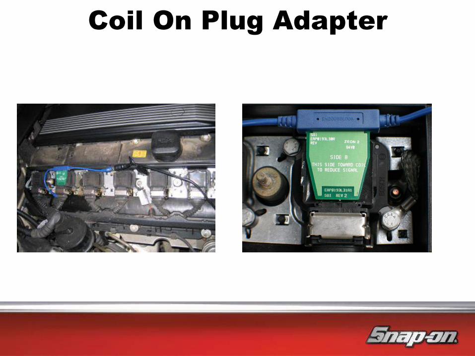
Coil On Plug Adapter
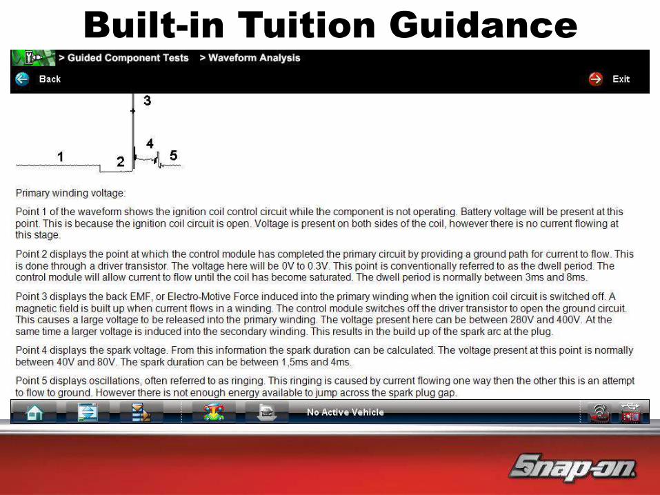
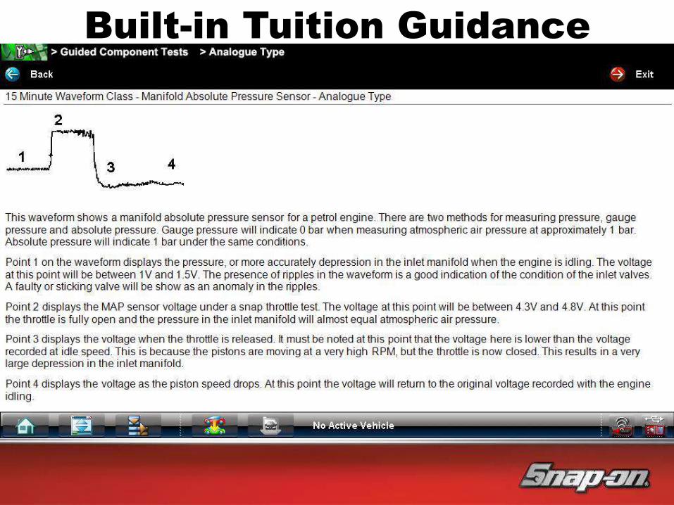
Built-in Tuition Guidance

Ignition Coil Signal

Inputs Outputs
Basic System Layout
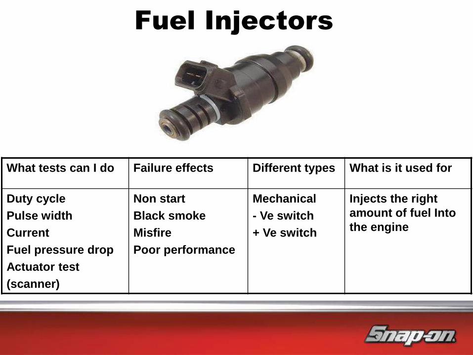
Fuel Injectors
What tests can I do Failure effects Different types What is it used for
Duty cycle
Pulse width
Current
Fuel pressure drop
Actuator test
(scanner)
Non start
Black smoke
Misfire
Poor performance
Mechanical
- Ve switch
+ Ve switch
Injects the right
amount of fuel Into
the engine
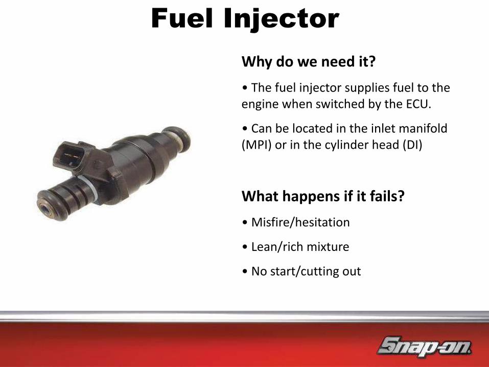
Fuel Injector
Why do we need it?
• The fuel injector supplies fuel to the engine when switched by the ECU.
• Can be located in the inlet manifold (MPI) or in the cylinder head (DI)
What happens if it fails?
• Misfire/hesitation
• Lean/rich mixture
• No start/cutting out
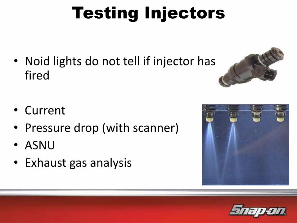
• Noid lights do not tell if injector has fired
• Current
• Pressure drop (with scanner)
• ASNU
• Exhaust gas analysis
Testing Injectors
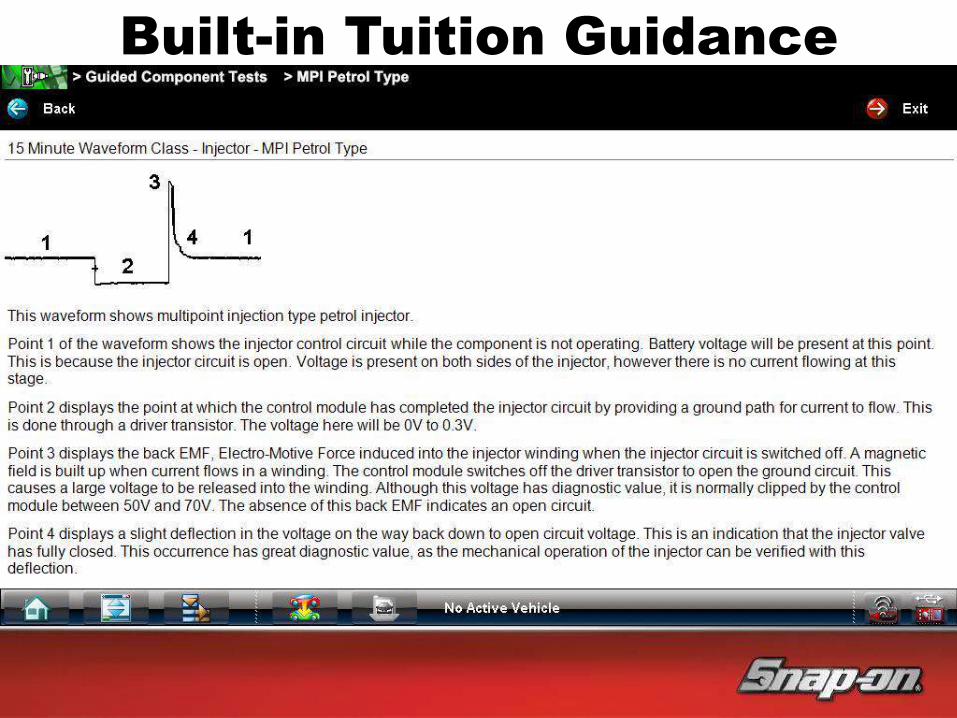
Built-in Tuition Guidance
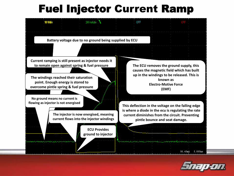
Fuel Injector Current Ramp
Battery voltage due to no ground being supplied by ECU
No ground means no current is flowing as injector is not energised
ECU Provides ground to injector
The injector is now energised, meaning current flows into the injector windings
The windings reached their saturation point. Enough energy is stored to
overcome pintle spring & fuel pressure
Current ramping is still present as injector needs it to remain open against spring & fuel pressure The ECU removes the ground supply, this
causes the magnetic field which has built up in the windings to be released. This is
known as Electro-Motive Force
(EMF)
This deflection in the voltage on the falling edge is where a diode in the ecu is regulating the rate current diminishes from the circuit. Preventing
pintle bounce and seat damage.

Injector Voltage (Request)
Injector (Amps)
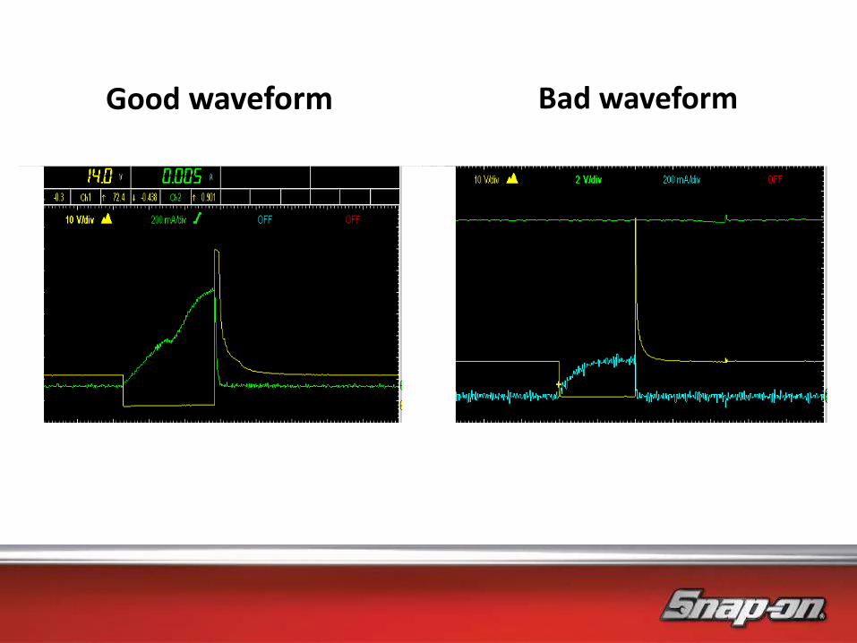
Good waveform Bad waveform

Piezo Injector Driver Signal
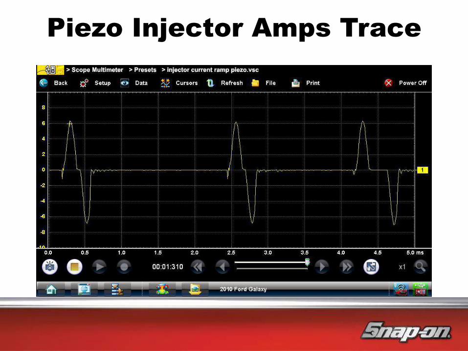
Piezo Injector Amps Trace

Inputs Outputs
Basic System Layout

Crankshaft Sensor
What tests can I do Failure effects Different types What is it used for?
AC voltage
Resistance
Oscilloscope
Scanner
(engine speed)
Non start
Misfire
Hall effect
Ac generator
Magnetic
Engine speed
TDC reverence
Misfire detection
What is it used for?

CKP Crank Position Sensor
Crankshaft position sensor (what's it for)
• Engine position (ref cylinder 1 TDC)
• Engine speed
• Used for misfire detection
• Accurate engine timing in conjunction with cam sensor
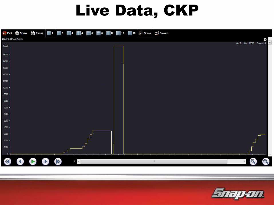
Live Data, CKP

Built-in Tuition Guidance
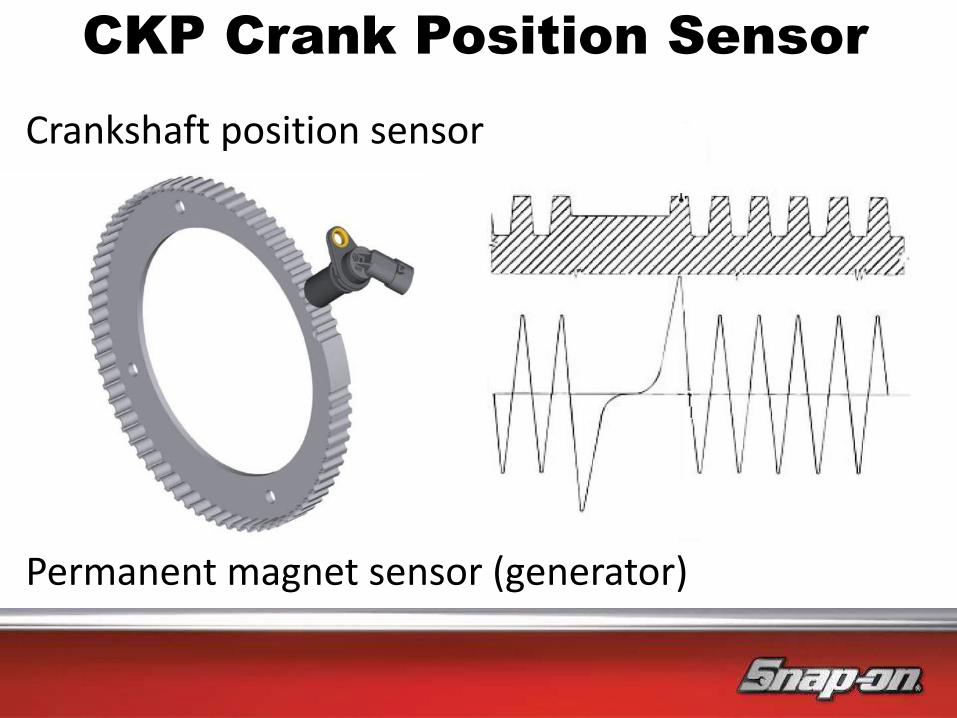
CKP Crank Position Sensor
Crankshaft position sensor
Permanent magnet sensor (generator)
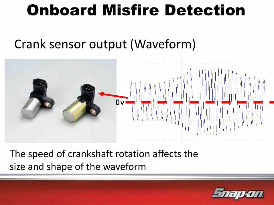
Crank sensor output (Waveform)
The speed of crankshaft rotation affects the size and shape of the waveform
0v
Onboard Misfire Detection

…the crank slows for compression
and accelerates on power…
Slow Fast
Onboard Misfire Detection

…so when a misfire occurs
the crank does not accelerate as expected…
Slow Fast Slow Fast Slow Slow Fast
Misfire Event
Onboard Misfire Detection

Case Study

Outputs
Basic System Layout
Inputs

Cam Position Sensor
What tests can I do Failure effects Different types What is it used for?
AC volts
Resistance
(inductive only)
DC volts
Oscilloscope
Non start
Misfire
Hall effect
Frequency
Inductive (AC)
Cylinder reference
Misfire detection
Engine position
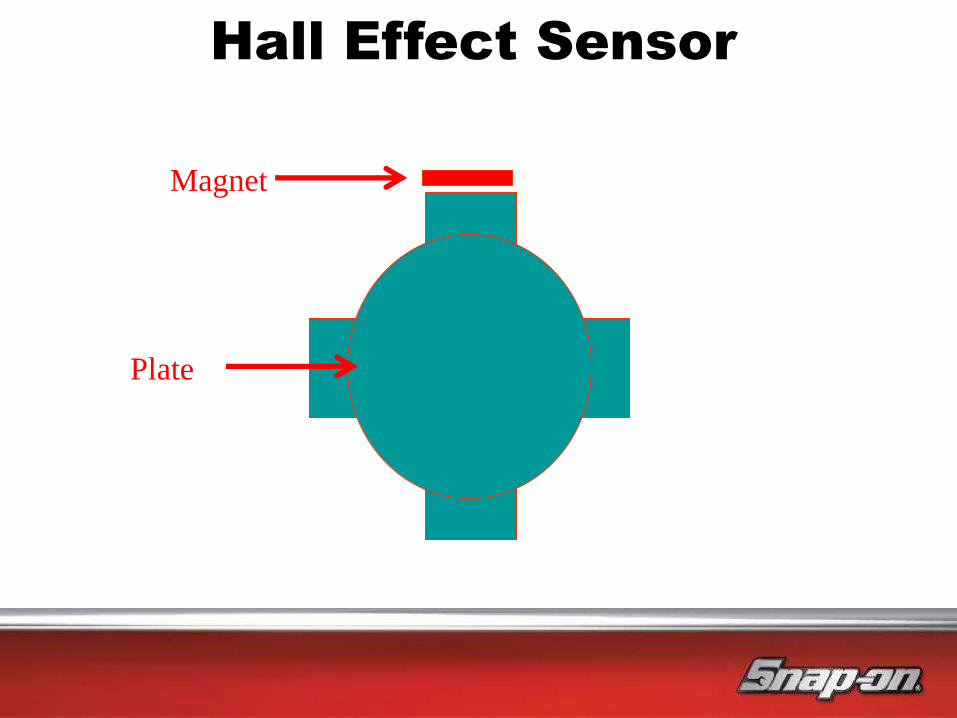
Hall Effect Sensor
Magnet
Plate

Digital Cam Sensor Testing

Analogue CMP Sensor Testing

Built-in Tuition Guidance

Inputs Outputs
Basic System Layout

Manifold Pressure Sensor
What tests can I do Failure effects Different types What is it used for
Volts
Frequency
Vacuum
No idle
Erratic Idle
Poor performance
Black smoke
Analogue
Digital
Sense engine load
Turbo control
Built-in Tuition Guidance

Map Sensor Signal
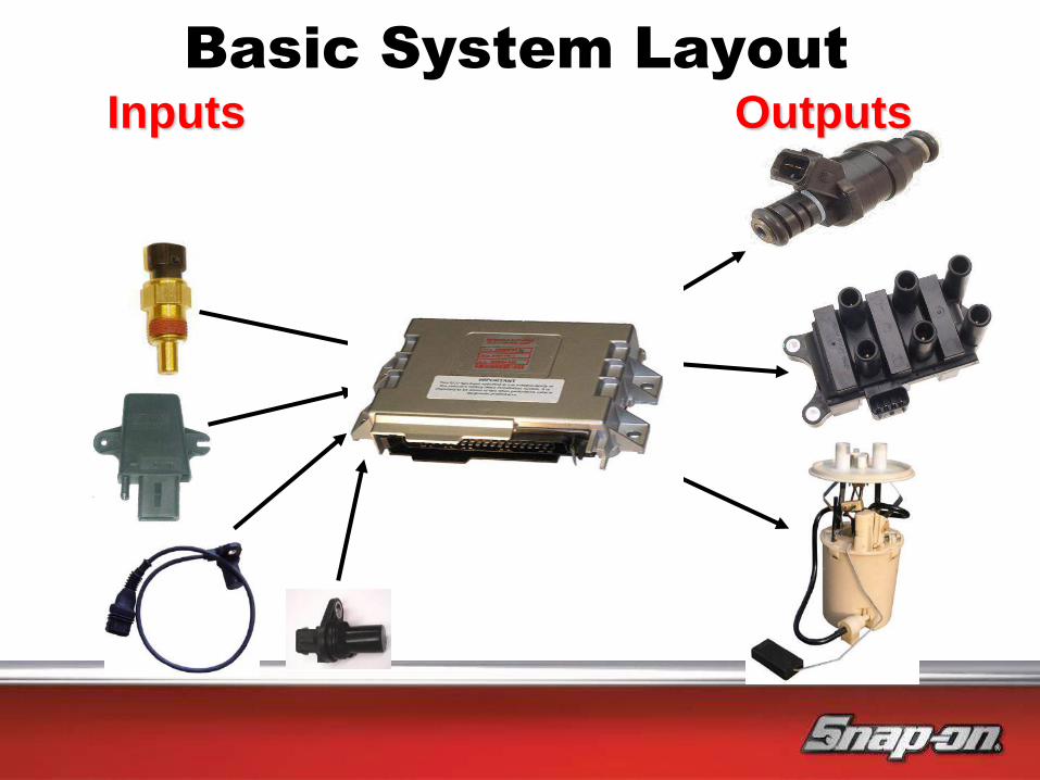
Inputs Outputs
Basic System Layout
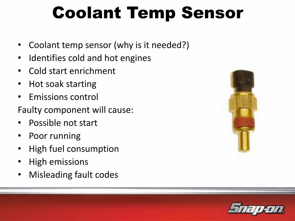
• Coolant temp sensor (why is it needed?)
• Identifies cold and hot engines
• Cold start enrichment
• Hot soak starting
• Emissions control
Faulty component will cause:
• Possible not start
• Poor running
• High fuel consumption
• High emissions
• Misleading fault codes
Coolant Temp Sensor

Outputs
Basic System Layout
Inputs

Throttle Position Sensor
What tests can I do Failure effects Different types What is it used for
Voltage
Frequency
Scanner
MIL on?
Analogue
Digital
Acceleration enrichment
Over-run fuel cut off
Auto box kick-down

5v +
0v -
Signal Return
0.25V 4.5V
TPS Sensor
TPS

TPS

TPS Signals
Outputs
Basic System Layout
Inputs
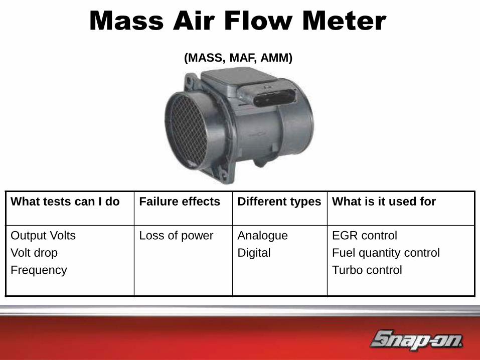
Mass Air Flow Meter
What tests can I do Failure effects Different types What is it used for
Output Volts
Volt drop
Frequency
Loss of power
Analogue
Digital
EGR control
Fuel quantity control
Turbo control
(MASS, MAF, AMM)

Live Data, AMM
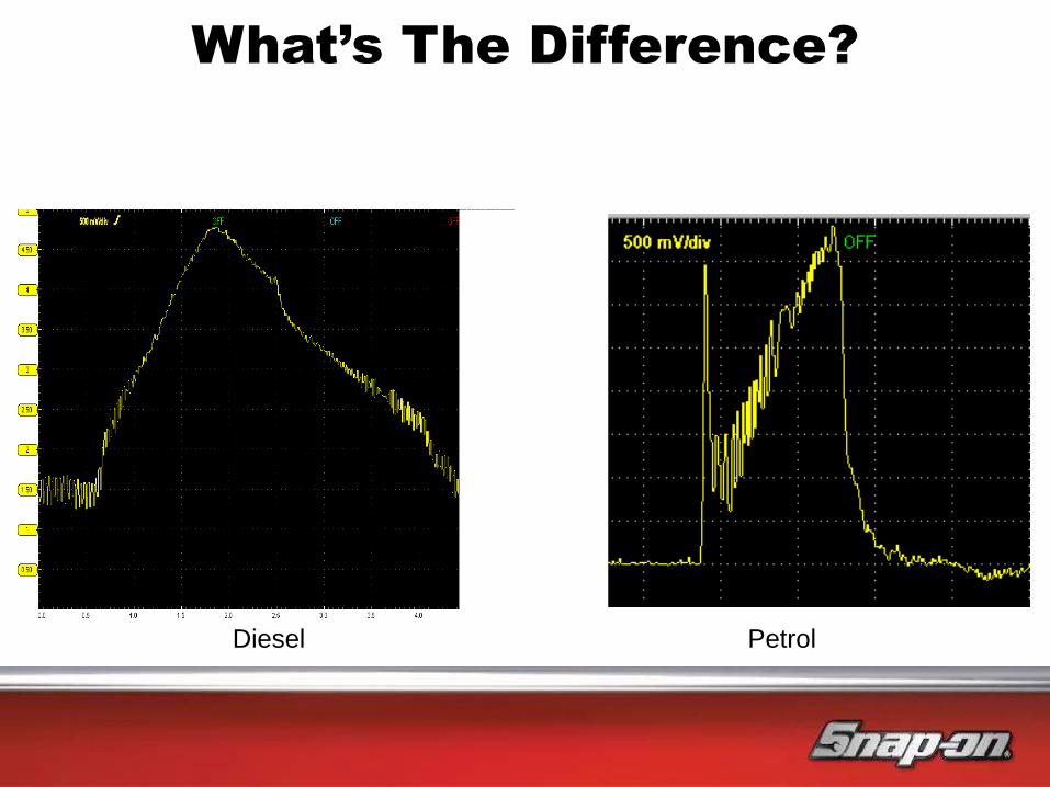
What’s The Difference?
Diesel Petrol

Built-in Tuition Guidance

Digital AMM

MAF Sensor Testing
Digital sensors give a square waveform which can be checked with an oscilloscope
This is a variable frequency signal that can be measured with a graphing meter

Outputs
Basic System Layout
Inputs
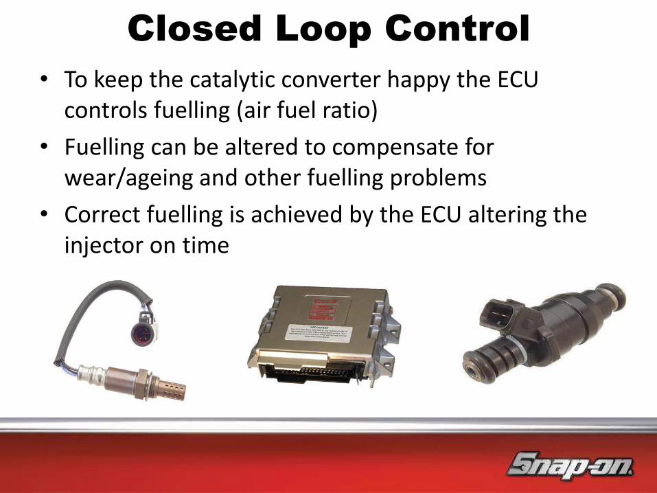
• To keep the catalytic converter happy the ECU controls fuelling (air fuel ratio)
• Fuelling can be altered to compensate for wear/ageing and other fuelling problems
• Correct fuelling is achieved by the ECU altering the injector on time
Closed Loop Control

Heater Oxygen Sensor
What tests can
I do
Failure
effects
Different types What is it used for
Voltage
Current
Frequency
Incorrect
fuelling
Surging at
cruise
Zirconia
Titania
Wideband
Fuel control
Catalytic converter testing
B1S1, Pre catalytic converter
B1S2, Post catalytic converter

Built-in Tuition Guidance

By increasing and reducing the Injector Pulse Width, the PCM can satisfy two important functions:
1. Send measurements to the PCM so that it can maintain the A/F at a desired 14.7:1 ratio (stoichiometric)
2. Maintain an efficient Catalytic Converter.
O2 Sensor Closed Loop

Zirconia Sensor
1 Hertz
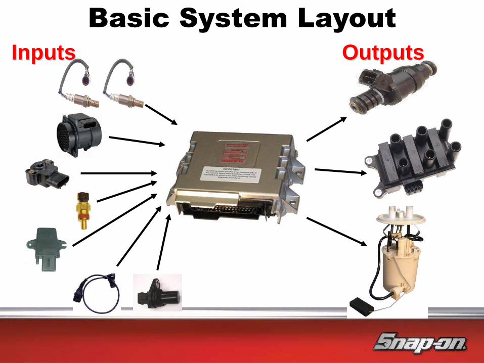
Outputs
Basic System Layout
Inputs

Pre Cat Sensor
Upstream
Post Cat Sensor
Downstream
Post Cat Oxygen Sensor
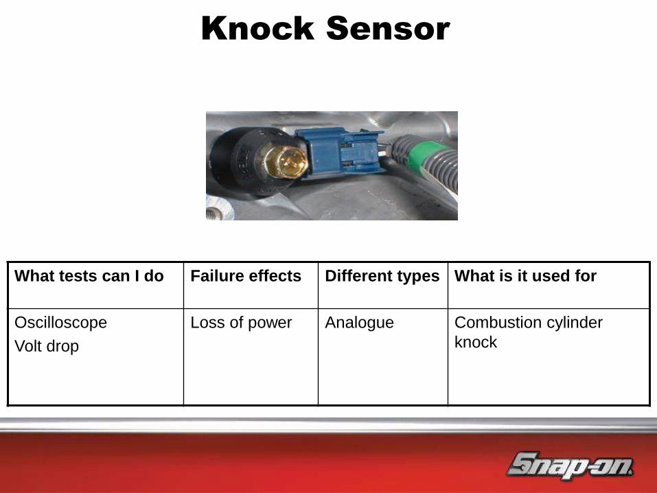
Knock Sensor
What tests can I do Failure effects Different types What is it used for
Oscilloscope
Volt drop
Loss of power
Analogue Combustion cylinder
knock
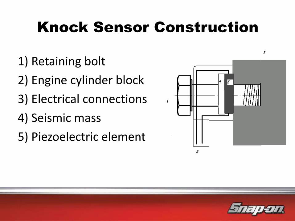
Knock Sensor Construction
1) Retaining bolt
2) Engine cylinder block
3) Electrical connections
4) Seismic mass
5) Piezoelectric element
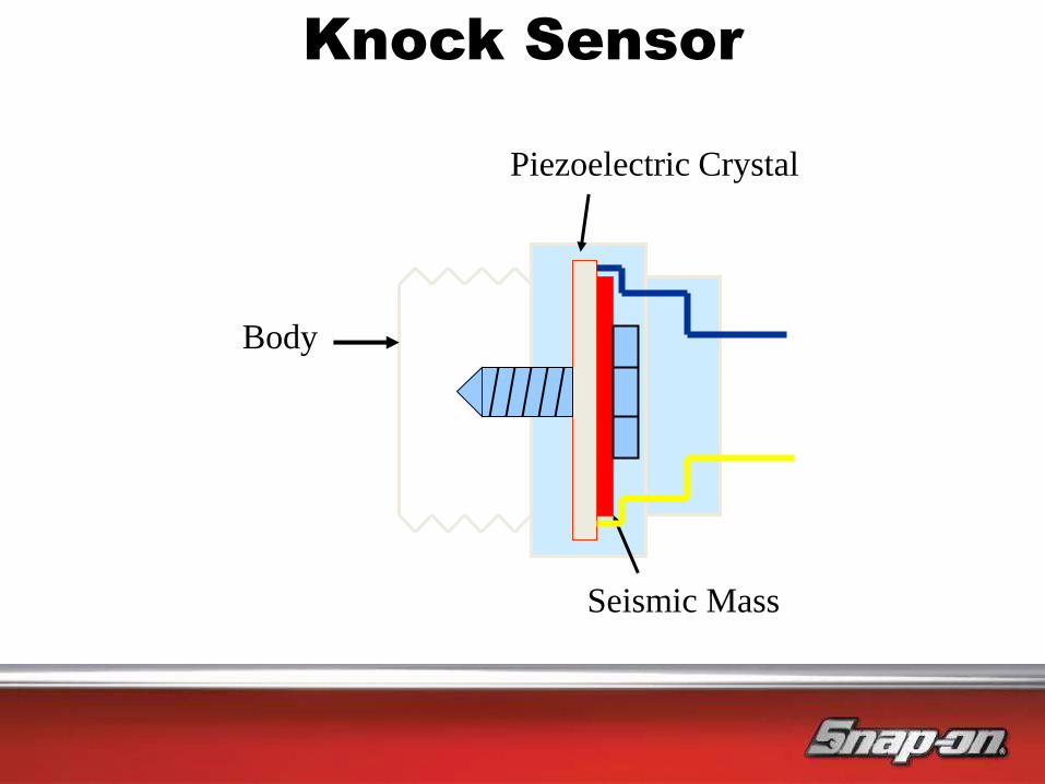
Body
Piezoelectric Crystal
Seismic Mass
Knock Sensor
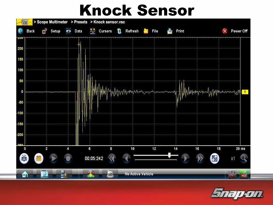
Knock Sensor
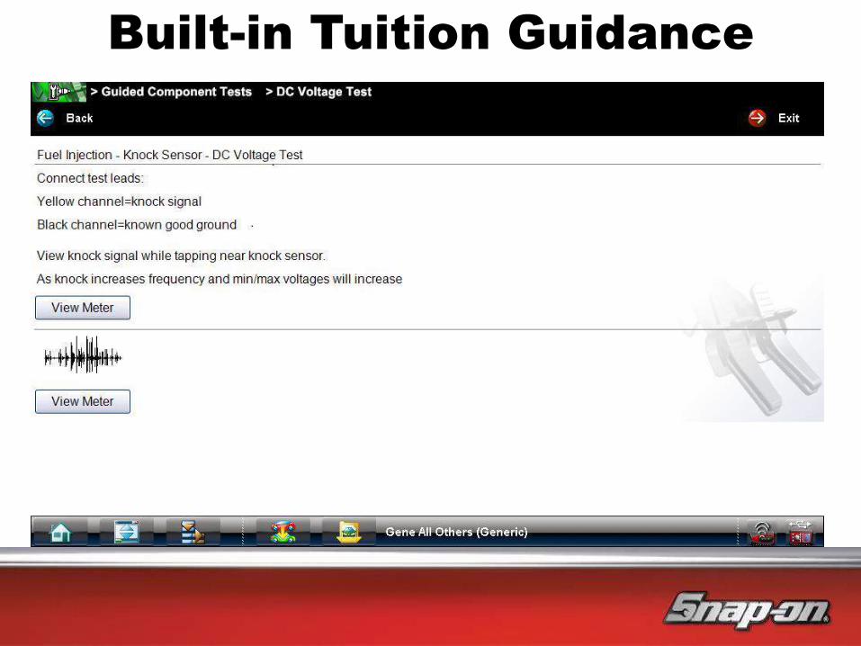
Built-in Tuition Guidance

QUICK BREAK

Live VERUS Pro Demo

MODERN DAY DIAGNOSTICS
What is the key to profitable
vehicle diagnostics?

MODERN DAY DIAGNOSTICS
What is the key to profitable vehicle
diagnostics?
Can we still apply the same “tried and
true” diagnostics methods from before?

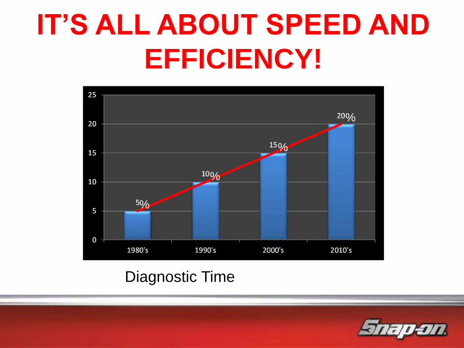
IT’S ALL ABOUT SPEED AND
EFFICIENCY!
Average diagnostic charge is £20 per hook up
Average charge per healthcheck is £10
The more you do the more money you
make
%
%
%
%
IT’S ALL ABOUT SPEED AND
EFFICIENCY!
Diagnostic Time

Diagnostic Tool Return on Investment
Input in blue coloured cells:
How long will you, or have you had your tool? 24 Mth
How many times do you hook up per week? 5
What is your diagnostic charge? £25
How many Health Checks per week? 5
What is your Health Check charge? £25
Total you have spent on subscription? £1889.76
How much did you pay for your tool ? £2911.92
Income generated since you bought the tool £26,000
Total Profit for the 24 Months £21,198
RETURN ON INVESTMENT

RETURN ON INVESTMENT

VERUS PRO BENEFITS
1. JOB CARD: A permanent time, dated recorded history of the vehicle (with
DTCs and additional notes or attachments)
2. KNOWN GOOD VALUES: History of scope comparisons
3. COMPONENT TEST METER: Shows you where and how to connect, tells
you what the results should be and the possible causes
4. INFORMATION: Component locations and wiring diagrams
5. INTERNET ENABLED: For diagnostic forums and information

RETURN ON INVESTMENT

We hope tonight’s presentation has been of interest to you, and that we have been able to answer some of those questions you
always wanted to ask.
Thank You
![Introduction of Advanced Measutal (Model : CDG-0004)220]20071120173728.pdf · 1 Crank Throw Measuring Point Purpose of measuring the crankshaft deflection Checking the rectilinearity](https://img.pdfslide.us/doc/110x75/5ab6cfe67f8b9a2f438e131c/introduction-of-advanced-measutal-model-cdg-0004-22020071120173728pdf1-crank.jpg)


![DESIGN AND STRESS ANALYSIS OF CRANKSHAFT · PDF filethe exact amount of crankshaft deflection (front } U Z v vP]v [ Ço]v running behind those in the front. Depending](https://img.pdfslide.us/doc/110x75/5ab6cfe67f8b9a2f438e134a/design-and-stress-analysis-of-crankshaft-exact-amount-of-crankshaft-deflection.jpg)