Embed Size (px)
Citation preview
ADM X3®Mobile Bearing Hip™ System
Surgical Protocol
For Use With Restoration ADMCups and Inserts
Available with X3 AdvancedBearing Technology
Warnings and Precautions . . . . . . . . . . . . . . . . . . . . . . . . . . . . . . . . . . . . . . . . . . . . . . . . . . 1Introduction . . . . . . . . . . . . . . . . . . . . . . . . . . . . . . . . . . . . . . . . . . . . . . . . . . . . . . . . . . . . . . . 2Design Rationale . . . . . . . . . . . . . . . . . . . . . . . . . . . . . . . . . . . . . . . . . . . . . . . . . . . . . . . . . . . 2Step 1 . . . . . . . . . . . . . . . . . . . . . . . . . . . . . . . . . . . . . . . . . . . . . . . . . . . . . . . . . . . . . . . . . . . . . 4Pre-operative Planning and X-ray Evaluation . . . . . . . . . . . . . . . . . . . . . . . . . . . . . . .4
Step 2 . . . . . . . . . . . . . . . . . . . . . . . . . . . . . . . . . . . . . . . . . . . . . . . . . . . . . . . . . . . . . . . . . . . . . 4Acetabular Preparation . . . . . . . . . . . . . . . . . . . . . . . . . . . . . . . . . . . . . . . . . . . . . . . . . .4
Step 3 . . . . . . . . . . . . . . . . . . . . . . . . . . . . . . . . . . . . . . . . . . . . . . . . . . . . . . . . . . . . . . . . . . . . . 4Spherical Reaming . . . . . . . . . . . . . . . . . . . . . . . . . . . . . . . . . . . . . . . . . . . . . . . . . . . . .4
Step 4 . . . . . . . . . . . . . . . . . . . . . . . . . . . . . . . . . . . . . . . . . . . . . . . . . . . . . . . . . . . . . . . . . . . . . 6Trial Evaluation of the Restoration ADM Cup . . . . . . . . . . . . . . . . . . . . . . . . . . . . . .6
Step 5 . . . . . . . . . . . . . . . . . . . . . . . . . . . . . . . . . . . . . . . . . . . . . . . . . . . . . . . . . . . . . . . . . . . . . 7Restoration ADM Cup Implantation . . . . . . . . . . . . . . . . . . . . . . . . . . . . . . . . . . . . . .7
Step 6 . . . . . . . . . . . . . . . . . . . . . . . . . . . . . . . . . . . . . . . . . . . . . . . . . . . . . . . . . . . . . . . . . . . . . .9Insert/Head Trial Reduction . . . . . . . . . . . . . . . . . . . . . . . . . . . . . . . . . . . . . . . . . . . . .9
Step 7 . . . . . . . . . . . . . . . . . . . . . . . . . . . . . . . . . . . . . . . . . . . . . . . . . . . . . . . . . . . . . . . . . . . . .10Insert/Head Implantation . . . . . . . . . . . . . . . . . . . . . . . . . . . . . . . . . . . . . . . . . . . . . .10
Step 8 . . . . . . . . . . . . . . . . . . . . . . . . . . . . . . . . . . . . . . . . . . . . . . . . . . . . . . . . . . . . . . . . . . . . .10Reduction and Closure . . . . . . . . . . . . . . . . . . . . . . . . . . . . . . . . . . . . . . . . . . . . . . . . .10Removal of Cup . . . . . . . . . . . . . . . . . . . . . . . . . . . . . . . . . . . . . . . . . . . . . . . . . . . . . .11Removal of Insert and Head Unit . . . . . . . . . . . . . . . . . . . . . . . . . . . . . . . . . . . . . . . .11
Catalog Information . . . . . . . . . . . . . . . . . . . . . . . . . . . . . . . . . . . . . . . . . . . . . . . . . . . . . . 14Restoration ADM General Instrument Tray . . . . . . . . . . . . . . . . . . . . . . . . . . . . . . .14Femoral Head Trials . . . . . . . . . . . . . . . . . . . . . . . . . . . . . . . . . . . . . . . . . . . . . . . . . . .14Restoration ADM Right Cup Instruments Tray . . . . . . . . . . . . . . . . . . . . . . . . . . . . .15Restoration ADM Left Cup Instruments Tray . . . . . . . . . . . . . . . . . . . . . . . . . . . . . .15Restoration ADM Impaction Instruments Tray . . . . . . . . . . . . . . . . . . . . . . . . . . . .16CuttingEdge Acetabular Reamers . . . . . . . . . . . . . . . . . . . . . . . . . . . . . . . . . . . . . . . .16Restoration ADM Cup Implants . . . . . . . . . . . . . . . . . . . . . . . . . . . . . . . . . . . . . . . . .17Restoration ADM Insert Implants . . . . . . . . . . . . . . . . . . . . . . . . . . . . . . . . . . . . . . .17Restoration ADM X-ray Templates . . . . . . . . . . . . . . . . . . . . . . . . . . . . . . . . . . . . . . .17
ADM X3Mobile Bearing Hip System
Surgical Protocol
Indications
The indications for use of total hipreplacement prostheses include:
• Non-inflammatory degenerative joint disease including osteoarthritis and avascular necrosis
• Rheumatoid arthritis• Correction of functional deformity• Revision procedures where other treatments or devices have failed
• Treatment of non-union, femoral neck and trochanteric fractures of the proximal femur with head involvement that are unmanageable using other techniques
• Dislocation risks
This acetabular cup is intended for cementlessuse only.
Contraindications
• Overt infection• Distant foci of infections (which may cause hematogenous spread to the implant site)
• Rapid disease progression as manifested by joint destruction or bone resorption apparent on roentgenogram
• Skeletally immature patients• Cases where there is a loss of abductor musculature, poor bone stock, or poor skin coverage around the hip joint which wouldmake the procedure unjustifiable
Conditions presenting increasedrisk of failure include:
• Uncooperative patient or patient with neurologic disorders, incapable of followinginstructions
• Osteoporosis• Metabolic disorders which may impair bone formation
• Osteomalacia• Obesity
Warnings and Precautions
See package insert for warnings, precautions,adverse effects and other essential productinformation.
The Restoration ADM cup is intended foruse with the Restoration ADM insert only. It is not intended for use as a metal-on-metalarticulation. No testing has been conductedto determine that this bearing coupleproduces favorable mechanical outcomes.Only Stryker 28mm femoral heads shouldbe inserted into the ADM inserts. Further,Stryker strongly advises against the use ofanother manufacturer’s component withRestoration ADM. Any such use willnegate the responsibility of Stryker forthe performance of the resulting mixedcomponent implant.
Before using Restoration ADMinstrumentation, verify:• Instruments have been properly dis-assembled prior to cleaning and sterilization
• Instruments have been properly assembledpost-sterilization
• Instruments have maintained design integrity
• Proper size configurations are available• Restoration ADM instruments areonly compatible with RestorationADM implants
ADM X3Mobile Bearing Hip System
Surgical Protocol
1
Introduction
This surgical protocol is a guide to preparing the acetabulum for the RestorationADM acetabular implants utilizing Restoration ADM acetabular instruments andCuttingEdge acetabular reamers.
The Restoration ADM acetabular system is a two-piece component design that is assembled intra-operatively. Restoration ADM acetabular cups have a peripheralself-locking (PSL) build-up at the rim that provides a 1.5mm press-fit. Reaming isperformed line-to-line with the press-fit incorporated into the final implant (e.g.,52mm cup = 53.5mm periphery at the rim of the cup). Restoration ADM cups areavailable in left and right configurations ranging in sizes 46mm – 64mm OD, whichare coupled with polyethylene inserts ranging in sizes 40mm – 58mm OD. Thereis a 6mm difference between the cup and insert. Inserts are available in 0°, 28mm ID only.
Note: The Restoration ADM acetabular system must be utilized with CuttingEdgeacetabular reamers. Preparation of the acetabulum is required and spherical reaming is necessary to implant Restoration ADM cups.
Design Rationale
The Restoration ADM design is derived from a dual mobility cup concept whichhas over 30 years of successful clinical history. These results have shown decreaseddislocations and increased implant stability.1
Restoration ADM features an anatomic cup design that incorporates a notch atthe anterior portion of the cup to help avoid contact with the iliopsoas tendon.This anterior notch reduces the risk of cup and iliopsoas tendon impingementwhich helps to eliminate the occurrence of pain. Pain has been experienced inmal-positioned/protrusive hemispherical cups.4 Restoration ADM may also offer thepotential for reducing the incidence of femoral neck impingement which may leadto metallosis and potential construct failure.2
The Restoration ADM cup incorporates the following dual points of articulation:• 28mm femoral head and • Large polyethylene insert that mimicks a femoral head.
This insert provides increased range of motion and greater stability.3 The polyethyleneinsert, also referred to as the “effective head”, is available in large sizes that provideincreased jump distance in an effort to minimize hip dislocation.
This publication sets forth detailed recommended procedures for using Stryker Orthopaedics devices andinstruments. It offers guidance that you should heed, but, as with any such technical guide, each surgeonmust consider the particular needs of each patient and make appropriate adjustments when and as required.2
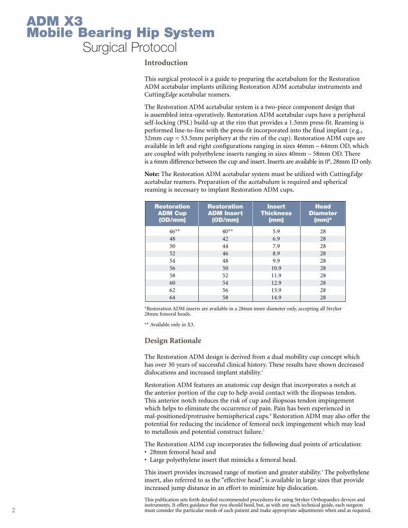
Restoration Restoration Insert HeadADM Cup ADM Insert Thickness Diameter(OD/mm) (OD/mm) (mm) (mm)*
46** 40** 5.9 2848 42 6.9 2850 44 7.9 2852 46 8.9 2854 48 9.9 2856 50 10.9 2858 52 11.9 2860 54 12.9 2862 56 13.9 2864 58 14.9 28
*Restoration ADM inserts are available in a 28mm inner diameter only, accepting all Stryker28mm femoral heads.
** Available only in X3.
ADM X3Mobile Bearing Hip System
Surgical Protocol

Surgical Protocol
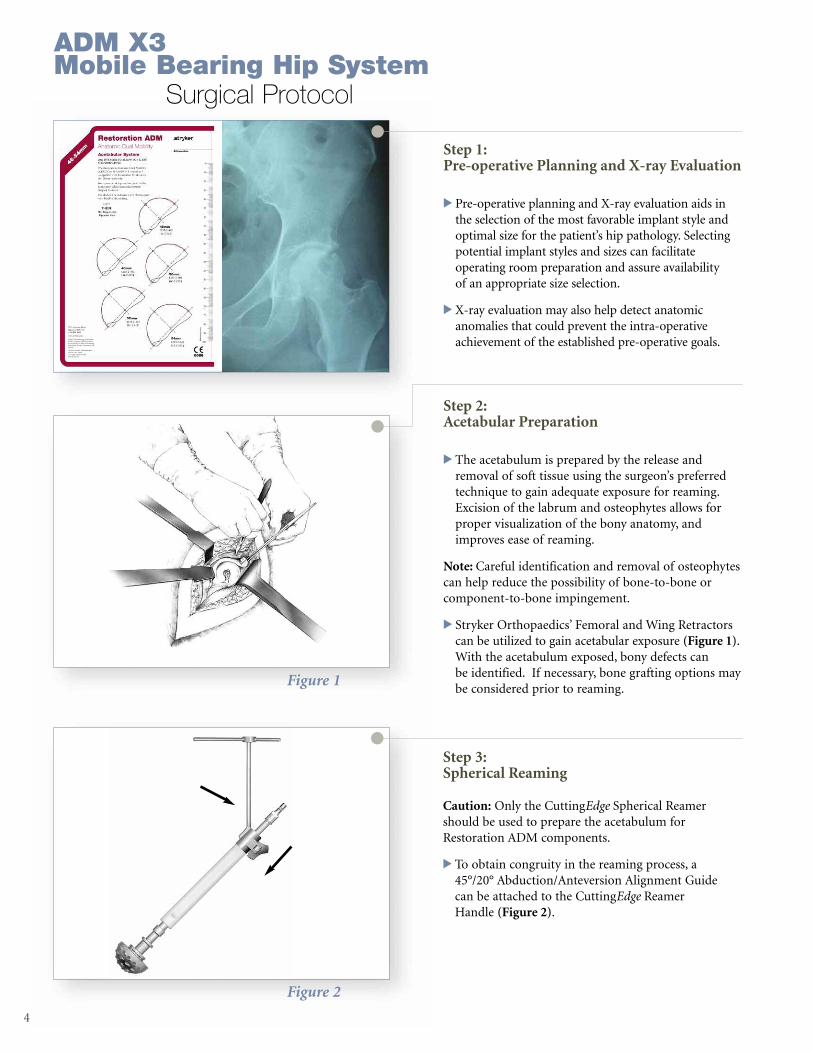
Figure 1
Figure 2
Step 1: Pre-operative Planning and X-ray Evaluation
> Pre-operative planning and X-ray evaluation aids in the selection of the most favorable implant style andoptimal size for the patient’s hip pathology. Selectingpotential implant styles and sizes can facilitate operating room preparation and assure availability of an appropriate size selection.
> X-ray evaluation may also help detect anatomic anomalies that could prevent the intra-operativeachievement of the established pre-operative goals.
4
Step 3: Spherical Reaming
Caution: Only the CuttingEdge Spherical Reamershould be used to prepare the acetabulum forRestoration ADM components.
> To obtain congruity in the reaming process, a 45°/20° Abduction/Anteversion Alignment Guide can be attached to the CuttingEdge Reamer Handle (Figure 2).
Step 2: Acetabular Preparation
> The acetabulum is prepared by the release andremoval of soft tissue using the surgeon’s preferredtechnique to gain adequate exposure for reaming.Excision of the labrum and osteophytes allows forproper visualization of the bony anatomy, andimproves ease of reaming.
Note: Careful identification and removal of osteophytescan help reduce the possibility of bone-to-bone orcomponent-to-bone impingement.
> Stryker Orthopaedics’ Femoral and Wing Retractorscan be utilized to gain acetabular exposure (Figure 1).With the acetabulum exposed, bony defects can be identified. If necessary, bone grafting options maybe considered prior to reaming.
ADM X3Mobile Bearing Hip System
Surgical Protocol
5
Figure 3
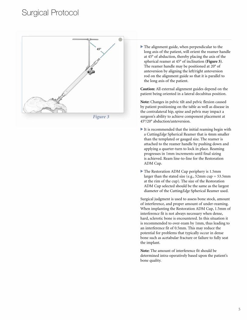
> The alignment guide, when perpendicular to the long axis of the patient, will orient the reamer handleat 45° of abduction, thereby placing the axis of thespherical reamer at 45° of inclination (Figure 3). The reamer handle may be positioned at 20° ofanteversion by aligning the left/right anteversion rod on the alignment guide so that it is parallel to the long axis of the patient.
Caution: All external alignment guides depend on thepatient being oriented in a lateral decubitus position.
Note: Changes in pelvic tilt and pelvic flexion caused by patient positioning on the table as well as disease inthe contralateral hip, spine and pelvis may impact asurgeon’s ability to achieve component placement at45°/20° abduction/anteversion.
> It is recommended that the initial reaming begin witha CuttingEdge Spherical Reamer that is 4mm smallerthan the templated or gauged size. The reamer isattached to the reamer handle by pushing down andapplying a quarter-turn to lock in place. Reaming progresses in 1mm increments until final sizing is achieved. Ream line-to-line for the RestorationADM Cup.
> The Restoration ADM Cup periphery is 1.5mm larger than the stated size (e.g., 52mm cup = 53.5mmat the rim of the cup). The size of the RestorationADM Cup selected should be the same as the largestdiameter of the CuttingEdge Spherical Reamer used.
Surgical judgment is used to assess bone stock, amountof interference, and proper amount of under-reaming.When implanting the Restoration ADM Cup, 1.5mm ofinterference fit is not always necessary when dense,hard, sclerotic bone is encountered. In this situation itis recommended to over-ream by 1mm, thus leading toan interference fit of 0.5mm. This may reduce thepotential for problems that typically occur in densebone such as acetabular fracture or failure to fully seatthe implant.
Note: The amount of interference fit should be determined intra-operatively based upon the patient’sbone quality.
45°
Surgical Protocol
Locking Sleeve
Figure 4
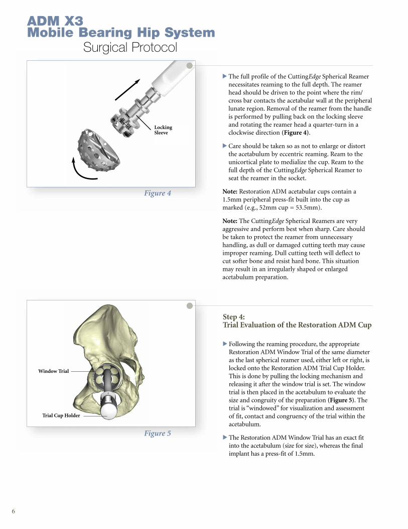
> The full profile of the CuttingEdge Spherical Reamernecessitates reaming to the full depth. The reamerhead should be driven to the point where the rim/cross bar contacts the acetabular wall at the peripherallunate region. Removal of the reamer from the handleis performed by pulling back on the locking sleeveand rotating the reamer head a quarter-turn in aclockwise direction (Figure 4).
> Care should be taken so as not to enlarge or distortthe acetabulum by eccentric reaming. Ream to the unicortical plate to medialize the cup. Ream to thefull depth of the CuttingEdge Spherical Reamer toseat the reamer in the socket.
Note: Restoration ADM acetabular cups contain a1.5mm peripheral press-fit built into the cup asmarked (e.g., 52mm cup = 53.5mm).
Note: The CuttingEdge Spherical Reamers are veryaggressive and perform best when sharp. Care shouldbe taken to protect the reamer from unnecessaryhandling, as dull or damaged cutting teeth may causeimproper reaming. Dull cutting teeth will deflect tocut softer bone and resist hard bone. This situationmay result in an irregularly shaped or enlargedacetabulum preparation.
6
Figure 5
Step 4: Trial Evaluation of the Restoration ADM Cup
> Following the reaming procedure, the appropriateRestoration ADM Window Trial of the same diameteras the last spherical reamer used, either left or right, islocked onto the Restoration ADM Trial Cup Holder.This is done by pulling the locking mechanism andreleasing it after the window trial is set. The windowtrial is then placed in the acetabulum to evaluate thesize and congruity of the preparation (Figure 5). Thetrial is “windowed” for visualization and assessmentof fit, contact and congruency of the trial within theacetabulum.
> The Restoration ADM Window Trial has an exact fitinto the acetabulum (size for size), whereas the finalimplant has a press-fit of 1.5mm.
Window Trial
Trial Cup Holder
ADM X3Mobile Bearing Hip System
Surgical Protocol
Cup HolderRod
Cup HolderHandle
7
Figure 7
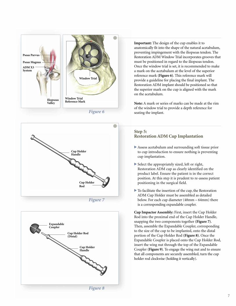
Important: The design of the cup enables it toanatomically fit into the shape of the natural acetabulum,preventing impingement with the iliopsoas tendon. TheRestoration ADM Window Trial incorporates grooves thatmust be positioned in regard to the iliopsoas tendon.Once the window trial is set, it is recommended to makea mark on the acetabulum at the level of the superiorreference mark (Figure 6). This reference mark willprovide a guideline for placing the final implant. TheRestoration ADM implant should be positioned so thatthe superior mark on the cup is aligned with the markon the acetabulum.
Note: A mark or series of marks can be made at the rimof the window trial to provide a depth reference forseating the implant.
Step 5: Restoration ADM Cup Implantation
> Assess acetabulum and surrounding soft tissue priorto cup introduction to ensure nothing is preventingcup implantation.
> Select the appropriately sized, left or right,Restoration ADM cup as clearly identified on theproduct label. Ensure the patient is in the correctposition. At this step it is prudent to re-assess patientpositioning in the surgical field.
> To facilitate the insertion of the cup, the RestorationADM Cup Holder must be assembled as detailedbelow. For each cup diameter (48mm – 64mm) thereis a corresponding expandable coupler.
Cup Impactor Assembly: First, insert the Cup HolderRod into the proximal end of the Cup Holder Handle,snapping the two components together (Figure 7).Then, assemble the Expandable Coupler, correspondingto the size of the cup to be implanted, onto the distalportion of the Cup Holder Rod (Figure 8). Once theExpandable Coupler is placed onto the Cup Holder Rod,insert the wing nut through the top of the ExpandableCoupler (Figure 9). To engage the wing nut and to ensurethat all components are securely assembled, turn the cupholder rod clockwise (holding it vertically).
Window Trial
Window TrialReference Mark
Figure 6
Figure 5
ExpandableCoupler
Cup Holder Rod(Distal)
Cup HolderHandle
Figure 8
Psoas Parvus
Psoas Magnus
ADM X3System
IliopsoasValley
8
Step 5: Restoration ADM Cup Implantation (Continued)
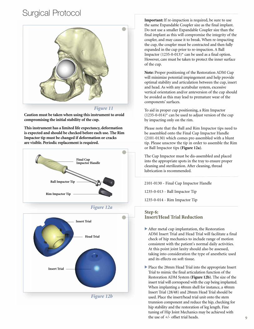
Note:When securing all components, be sure to onlyturn the Cup Holder Rod several turns–just enough tolock all components together. Turning the Cup HolderRod too much or until tightened will expand the coupler prematurely, preventing it from properly fittingonto the implant when preparing for implantation.
Notice that the Expandable Coupler has a reference mark (that lines up with the axis of the handle) thatcorresponds to the superior reference mark on theimplant. The gray stripes engraved on either side of thereference mark on the Expandable Coupler indicate theposition of the cup notch (right or left) for the iliopsoastendon (Figure 10).
>While the implant is still in the packaging, place theCup Holder vertically into it, making certain to alignthe cup and the Expandable Coupler reference marksfor proper Cup Holder/implant orientation and fit(Figure 10). While maintaining the position of thecup, turn the Cup Holder handle to tighten the cuponto the end of the Cup Holder and prepare it forplacement into the acetabulum.
Note: The Expandable Coupler must be fully seated within the implant before tightening. Fully seating theExpandable Coupler can be achieved by pressing it vertically into the cup, while placed on a table. When fullyseated, begin tightening the Expandable Coupler onto thecup for a secure fit. Following these instructions will helpreduce the risk of the cup and Expandable Coupler/CupHolder from disengaging during impaction.
>Cup Placement: Locate the reference mark made previously on the acetabulum. Position the cupaccording to the preset reference mark. Positioningthe cup according to the preset reference markwill ensure proper anatomic cup placement. Impactthe cup into the acetabulum (Figure 11). Once thecup is securely impacted, remove the cup holderfrom the cup by turning the cup holder rod counter-clockwise and pulling the cup holder backwards withminimal force.
Figure 9
Figure 10
Wing Nut
ExpandableCoupler
Cup HolderHandle
Cup HolderRod
Gray Stripe
ImplantSuperiorPolarReferenceMark
Gray Stripe
ExpandableCouplerReferenceMark
ADM X3Mobile Bearing Hip System
Surgical Protocol
9
Surgical Protocol Important: If re-impaction is required, be sure to use the same Expandable Coupler size as the final implant.Do not use a smaller Expandable Coupler size than thefinal implant as this will compromise the integrity of the coupler, and may cause it to break. When re-impactingthe cup, the coupler must be contracted and then fullyexpanded in the cup prior to re-impaction. A BallImpactor (1235-0-013)* can be used as a final option.However, care must be taken to protect the inner surfaceof the cup.
Note: Proper positioning of the Restoration ADM Cupwill minimize potential impingement and help provide optimal stability and articulation between the cup, insertand head. As with any acetabular system, excessive vertical orientation and/or anteversion of the cup shouldbe avoided as this may lead to premature wear of thecomponents’ surfaces.
To aid in proper cup positioning, a Rim Impactor (1235-0-014)* can be used to adjust version of the cupby impacting only on the rim.
Please note that the Ball and Rim Impactor tips need tobe assembled onto the Final Cup Impactor Handle(2101-0130) which comes pre-assembled with a blunttip. Please unscrew the tip in order to assemble the Rimor Ball Impactor tips (Figure 12a).
The Cup Impactor must be dis-assembled and placedinto the appropriate spots in the tray to ensure propercleaning and sterilization. After cleaning, threadlubrication is recommended.
Figure 11
Figure 12b
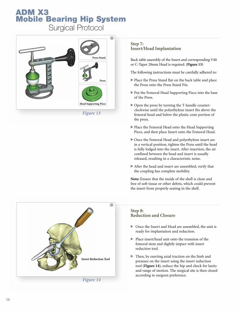
Step 6: Insert/Head Trial Reduction
> After metal cup implantation, the Restoration ADM Insert Trial and Head Trial will facilitate a finalcheck of hip mechanics to include range of motionconsistent with the patient's normal daily activities.At this point joint laxity should also be assessed,taking into consideration the type of anesthetic usedand its effects on soft tissue.
> Place the 28mm Head Trial into the appropriate Insert Trial to mimic the final articulation function of the Restoration ADM System (Figure 12b). The size of the insert trial will correspond with the cup being implanted. When implanting a 48mm shell for instance, a 48mm Insert Trial (28/48) and 28mm Head Trial should be used. Place the insert/head trial unit onto the stem trunnion component and reduce the hip, checking for hip stability and the restoration of leg length. Finetuning of Hip Joint Mechanics may be achieved with the use of +/- offset trial heads.
Insert Trial
Head Trial
Insert Trial
Figure 12a
2101-0130 - Final Cup Impactor Handle
1235-0-013 - Ball Impactor Tip
1235-0-014 - Rim Impactor Tip
Ball Impactor Tip
Rim Impactor Tip
Final CupImpactor Handle
Caution must be taken when using this instrument to avoidcompromising the initial stability of the cup.
This instrument has a limited life expectancy, deformationis expected and should be checked before each use. The RimImpactor tip must be changed if deformation or cracksare visible. Periodic replacement is required.
10
Figure 13
Figure 14
Step 8: Reduction and Closure
> Once the Insert and Head are assembled, the unit is ready for implantation and reduction.
> Place insert/head unit onto the trunnion of the femoral stem and slightly impact with insert reduction tool.
> Then, by exerting axial traction on the limb and pressure on the insert using the insert reduction tool (Figure 14), reduce the hip and check for laxity and range of motion. The surgical site is then closed according to surgeon preference.
Step 7: Insert/Head Implantation
Back table assembly of the Insert and corresponding V40or C-Taper 28mm Head is required. (Figure 13)
The following instructions must be carefully adhered to:
> Place the Press Stand flat on the back table and placethe Press onto the Press Stand Pin.
> Put the Femoral Head Supporting Piece into the baseof the Press.
>Open the press by turning the T-handle counter-clockwise until the polyethylene insert fits above thefemoral head and below the plastic cone portion ofthe press.
> Place the Femoral Head onto the Head SupportingPiece, and then place Insert onto the Femoral Head.
>Once the Femoral Head and polyethylene insert arein a vertical position, tighten the Press until the headis fully lodged into the insert. After insertion, the air confined between the head and insert is usuallyreleased, resulting in a characteristic noise.
> After the head and insert are assembled, verify thatthe coupling has complete mobility.
Note: Ensure that the inside of the shell is clean andfree of soft tissue or other debris, which could preventthe insert from properly seating in the shell.
Press Stand
Press
Head Supporting Piece
Insert Reduction Tool
ADM X3Mobile Bearing Hip System
Surgical Protocol
11
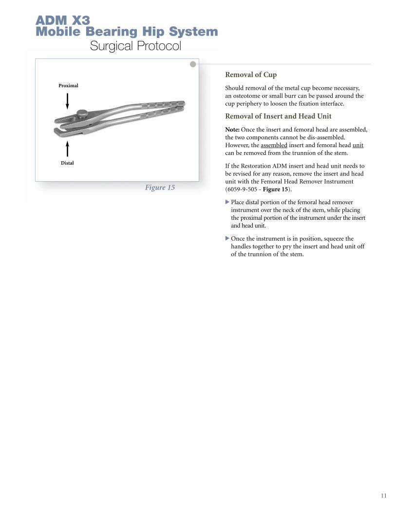
Removal of Cup
Should removal of the metal cup become necessary,an osteotome or small burr can be passed around thecup periphery to loosen the fixation interface.
Removal of Insert and Head Unit
Note: Once the insert and femoral head are assembled,the two components cannot be dis-assembled.However, the assembled insert and femoral head unitcan be removed from the trunnion of the stem.
If the Restoration ADM insert and head unit needs tobe revised for any reason, remove the insert and headunit with the Femoral Head Remover Instrument(6059-9-505 - Figure 15).
> Place distal portion of the femoral head removerinstrument over the neck of the stem, while placing the proximal portion of the instrument under the insertand head unit.
>Once the instrument is in position, squeeze the handles together to pry the insert and head unit offof the trunnion of the stem.
Figure 15
Proximal
Distal
ADM X3Mobile Bearing Hip System
Surgical Protocol

12

13
Catalog Information
14
Catalog Information
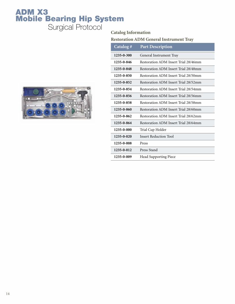
Restoration ADM General Instrument Tray
1235-0-300 General Instrument Tray
1235-0-846 Restoration ADM Insert Trial 28/46mm
1235-0-848 Restoration ADM Insert Trial 28/48mm
1235-0-850 Restoration ADM Insert Trial 28/50mm
1235-0-852 Restoration ADM Insert Trial 28/52mm
1235-0-854 Restoration ADM Insert Trial 28/54mm
1235-0-856 Restoration ADM Insert Trial 28/56mm
1235-0-858 Restoration ADM Insert Trial 28/58mm
1235-0-860 Restoration ADM Insert Trial 28/60mm
1235-0-862 Restoration ADM Insert Trial 28/62mm
1235-0-864 Restoration ADM Insert Trial 28/64mm
1235-0-000 Trial Cup Holder
1235-0-020 Insert Reduction Tool
1235-0-008 Press
1235-0-012 Press Stand
1235-0-009 Head Supporting Piece
Catalog # Part Description
ADM X3Mobile Bearing Hip System
Surgical Protocol
15
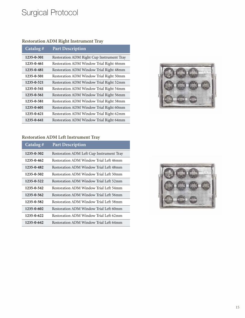
Restoration ADM Left Instrument Tray
1235-0-302 Restoration ADM Left Cup Instrument Tray
1235-0-462 Restoration ADM Window Trial Left 46mm
1235-0-482 Restoration ADM Window Trial Left 48mm
1235-0-502 Restoration ADM Window Trial Left 50mm
1235-0-522 Restoration ADM Window Trial Left 52mm
1235-0-542 Restoration ADM Window Trial Left 54mm
1235-0-562 Restoration ADM Window Trial Left 56mm
1235-0-582 Restoration ADM Window Trial Left 58mm
1235-0-602 Restoration ADM Window Trial Left 60mm
1235-0-622 Restoration ADM Window Trial Left 62mm
1235-0-642 Restoration ADM Window Trial Left 64mm
Catalog # Part Description
Surgical Protocol
Restoration ADM Right Instrument Tray
Catalog # Part Description
1235-0-301 Restoration ADM Right Cup Instrument Tray
1235-0-461 Restoration ADM Window Trial Right 46mm
1235-0-481 Restoration ADM Window Trial Right 48mm
1235-0-501 Restoration ADM Window Trial Right 50mm
1235-0-521 Restoration ADM Window Trial Right 52mm
1235-0-541 Restoration ADM Window Trial Right 54mm
1235-0-561 Restoration ADM Window Trial Right 56mm
1235-0-581 Restoration ADM Window Trial Right 58mm
1235-0-601 Restoration ADM Window Trial Right 60mm
1235-0-621 Restoration ADM Window Trial Right 62mm
1235-0-641 Restoration ADM Window Trial Right 64mm
16
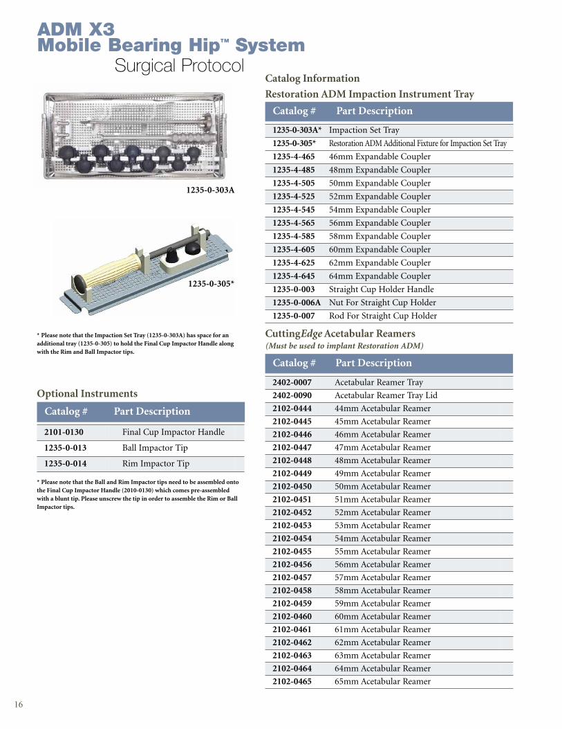
Catalog # Part Description
1235-0-303A* Impaction Set Tray
1235-0-305* Restoration ADM Additional Fixture for Impaction Set Tray
1235-4-465 46mm Expandable Coupler
1235-4-485 48mm Expandable Coupler
1235-4-505 50mm Expandable Coupler
1235-4-525 52mm Expandable Coupler
1235-4-545 54mm Expandable Coupler
1235-4-565 56mm Expandable Coupler
1235-4-585 58mm Expandable Coupler
1235-4-605 60mm Expandable Coupler
1235-4-625 62mm Expandable Coupler
1235-4-645 64mm Expandable Coupler
1235-0-003 Straight Cup Holder Handle
1235-0-006A Nut For Straight Cup Holder
1235-0-007 Rod For Straight Cup Holder
Catalog Information
Restoration ADM Impaction Instrument Tray
CuttingEdge Acetabular Reamers(Must be used to implant Restoration ADM)
Catalog # Part Description
2402-0007 Acetabular Reamer Tray
2402-0090 Acetabular Reamer Tray Lid
2102-0444 44mm Acetabular Reamer
2102-0445 45mm Acetabular Reamer
2102-0446 46mm Acetabular Reamer
2102-0447 47mm Acetabular Reamer
2102-0448 48mm Acetabular Reamer
2102-0449 49mm Acetabular Reamer
2102-0450 50mm Acetabular Reamer
2102-0451 51mm Acetabular Reamer
2102-0452 52mm Acetabular Reamer
2102-0453 53mm Acetabular Reamer
2102-0454 54mm Acetabular Reamer
2102-0455 55mm Acetabular Reamer
2102-0456 56mm Acetabular Reamer
2102-0457 57mm Acetabular Reamer
2102-0458 58mm Acetabular Reamer
2102-0459 59mm Acetabular Reamer
2102-0460 60mm Acetabular Reamer
2102-0461 61mm Acetabular Reamer
2102-0462 62mm Acetabular Reamer
2102-0463 63mm Acetabular Reamer
2102-0464 64mm Acetabular Reamer
2102-0465 65mm Acetabular Reamer
Optional Instruments
2101-0130 Final Cup Impactor Handle
1235-0-013 Ball Impactor Tip
1235-0-014 Rim Impactor Tip
Catalog # Part Description
* Please note that the Ball and Rim Impactor tips need to be assembled ontothe Final Cup Impactor Handle (2010-0130) which comes pre-assembledwith a blunt tip. Please unscrew the tip in order to assemble the Rim or BallImpactor tips.
* Please note that the Impaction Set Tray (1235-0-303A) has space for anadditional tray (1235-0-305) to hold the Final Cup Impactor Handle alongwith the Rim and Ball Impactor tips.
1235-0-303A
1235-0-305*
ADM X3Mobile Bearing Hip™ System
Surgical Protocol
17
Surgical Protocol
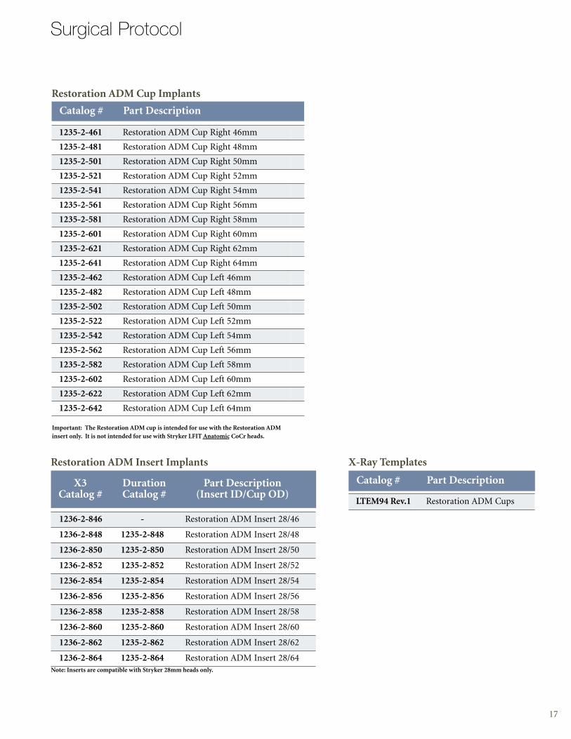
Restoration ADM Cup Implants
Catalog # Part Description
1235-2-461 Restoration ADM Cup Right 46mm
1235-2-481 Restoration ADM Cup Right 48mm
1235-2-501 Restoration ADM Cup Right 50mm
1235-2-521 Restoration ADM Cup Right 52mm
1235-2-541 Restoration ADM Cup Right 54mm
1235-2-561 Restoration ADM Cup Right 56mm
1235-2-581 Restoration ADM Cup Right 58mm
1235-2-601 Restoration ADM Cup Right 60mm
1235-2-621 Restoration ADM Cup Right 62mm
1235-2-641 Restoration ADM Cup Right 64mm
1235-2-462 Restoration ADM Cup Left 46mm
1235-2-482 Restoration ADM Cup Left 48mm
1235-2-502 Restoration ADM Cup Left 50mm
1235-2-522 Restoration ADM Cup Left 52mm
1235-2-542 Restoration ADM Cup Left 54mm
1235-2-562 Restoration ADM Cup Left 56mm
1235-2-582 Restoration ADM Cup Left 58mm
1235-2-602 Restoration ADM Cup Left 60mm
1235-2-622 Restoration ADM Cup Left 62mm
1235-2-642 Restoration ADM Cup Left 64mm
Important: The Restoration ADM cup is intended for use with the Restoration ADM insert only. It is not intended for use with Stryker LFIT Anatomic CoCr heads.
Note: Inserts are compatible with Stryker 28mm heads only.
Restoration ADM Insert Implants
1236-2-846 - Restoration ADM Insert 28/46
1236-2-848 1235-2-848 Restoration ADM Insert 28/48
1236-2-850 1235-2-850 Restoration ADM Insert 28/50
1236-2-852 1235-2-852 Restoration ADM Insert 28/52
1236-2-854 1235-2-854 Restoration ADM Insert 28/54
1236-2-856 1235-2-856 Restoration ADM Insert 28/56
1236-2-858 1235-2-858 Restoration ADM Insert 28/58
1236-2-860 1235-2-860 Restoration ADM Insert 28/60
1236-2-862 1235-2-862 Restoration ADM Insert 28/62
1236-2-864 1235-2-864 Restoration ADM Insert 28/64
X3 Duration Part DescriptionCatalog # Catalog # (Insert ID/Cup OD)
X-Ray Templates
LTEM94 Rev.1 Restoration ADM Cups
Catalog # Part Description

325 Corporate DriveMahwah, NJ 07430t: 201 831 5000
www.stryker.com
References:
1. Fessy M.H., “Dual Mobility: A Stéphanois Concept (St. Etienne Area, France),” Maitrise Orthopedique,March 2006.
2. Tracol P., Vandenbussche E., Deloge N., et. al., “Navigation Acetabular Anatomic Study Application in the Development of a New Implant,” EFORT Poster, May 2007.
3. Stryker Test Report: RD-06-078.
4. Vandenbussche E., Saffarini M., Deloge N., et al.,“Hemispheric Cups Do Not Reproduce Acetabular Rim Morphology”, Acta Orthopaedica 2007. 78 (3), 327-332.
A surgeon must always rely on his or her own professional clinical judgment when deciding whether to use aparticular product when treating a particular patient. Stryker does not dispense medical advice and recommendsthat surgeons be trained in the use of any particular product before using it in surgery.
The information presented is intended to demonstrate the breadth of Stryker product offerings. A surgeon mustalways refer to the package insert, product label and/or instructions for use before using any Stryker product.Products may not be available in all markets because product availability is subject to the regulatory and/ormedical practices in individual markets. Please contact your Stryker representative if you have questions about the availability of Stryker products in your area.
Stryker Corporation or its divisions or other corporate affiliated entities own, use or have applied for thefollowing trademarks or service marks: CuttingEdge, Mobile Bearing Hip, PSL, Restoration, Stryker, X3.All other trademarks are trademarks of their respective owners or holders.
Literature Number: LSP64 Rev. 2MS/GS 07/10
Copyright © 2010 StrykerPrinted in USA


![1 x Detection 10038 [P > 0.5 BAR] - Elfab · 2019. 1. 28. · 10038 [P > 0.5 BAR] 5 8 9 X3 Min X3 Min X3 Min X3 Min X3 X3 Ф T P Ф T T T T 1 x Detection 2 x Detection 6 7 Torque](https://img.pdfslide.us/doc/110x75/60ba177fcbcf900a842f11be/1-x-detection-10038-p-05-bar-elfab-2019-1-28-10038-p-05-bar.jpg)