Embed Size (px)
Citation preview
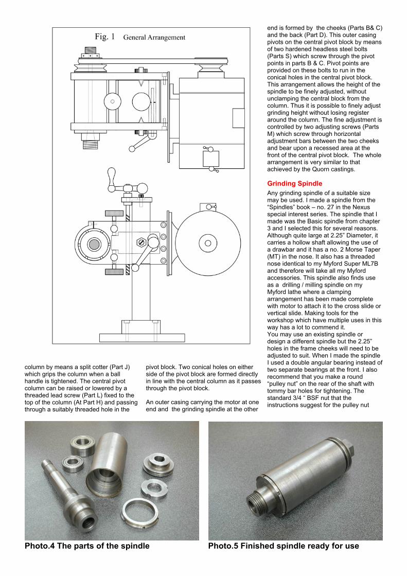
Carbide lapping machineA few years ago I purchased a Tiplap toollapping machine by Boremasters for areasonable price at a machinery auctionPhoto. 2. The machine had many of thefeatures of a Quorn tool and cuttergrinder, but the motor was fixed heightand had a fixed grinding wheel, limitingthe versatility of the machine. I set aboutmaking a bolt on column with anadjustable grinding head, capable of
using interchangeable grinding wheelsand I also added some other Quornfeatures to make it equal in every respectto the Quorn. The finished unit isillustrated in Photo. 3
Recently, several readers of MEW haveexpressed a wish to add an adjustablegrinding head behind a Worden tool andcutter grinder and also to build a Stenttype without castings. This unit can be
attached to any kind of tool grinder oreven be clamped to a lathe cross slide, soI thought it may have a wider appeal tomany readers.The designThe general Layout is shown in Fig 1. Abase plate (Part E in Fig.2) supports aColumn (Part G) via a steel mountingbush (Part F). The baseplate is clampedto the cutter grinder itself via two sliderails (Part I) which when the mountingsetscrews are loosened, allows thebaseplate to be slid from side to sidevarying the position of the column. Youwill see from Photo. 3 that in the case ofthe Tiplap machine, I found it best tomount the rails on an intermediate plate inorder to set the unit back a little and allowmore working space for the workhead tomove. If you create long rails, it will allowyou to rotate the head through 90 Deg., touse the circumference of the grindstoneand then slide the whole unit to the left toleave the grindstone still presented to thework.
Moving HeadOn the column is fixed a central pivotblock (Part A) and this is clamped to the
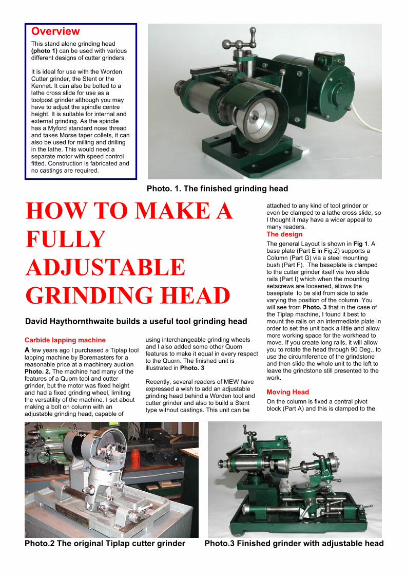
OverviewThis stand alone grinding head(photo 1) can be used with variousdifferent designs of cutter grinders.
It is ideal for use with the WordenCutter grinder, the Stent or theKennet. It can also be bolted to alathe cross slide for use as atoolpost grinder although you mayhave to adjust the spindle centreheight. It is suitable for internal andexternal grinding. As the spindlehas a Myford standard nose threadand takes Morse taper collets, it canalso be used for milling and drillingin the lathe. This would need aseparate motor with speed controlfitted. Construction is fabricated andno castings are required.
HOW TO MAKE AFULLYADJUSTABLEGRINDING HEADDavid Haythornthwaite builds a useful tool grinding head
Photo. 1. The finished grinding head
Photo.2 The original Tiplap cutter grinder Photo.3 Finished grinder with adjustable head
column by means a split cotter (Part J)which grips the column when a ballhandle is tightened. The central pivotcolumn can be raised or lowered by athreaded lead screw (Part L) fixed to thetop of the column (At Part H) and passingthrough a suitably threaded hole in the
pivot block. Two conical holes on eitherside of the pivot block are formed directlyin line with the central column as it passesthrough the pivot block.
An outer casing carrying the motor at oneend and the grinding spindle at the other
end is formed by the cheeks (Parts B& C)and the back (Part D). This outer casingpivots on the central pivot block by meansof two hardened headless steel bolts(Parts S) which screw through the pivotpoints in parts B & C. Pivot points areprovided on these bolts to run in theconical holes in the central pivot block.This arrangement allows the height of thespindle to be finely adjusted, withoutunclamping the central block from thecolumn. Thus it is possible to finely adjustgrinding height without losing registeraround the column. The fine adjustment iscontrolled by two adjusting screws (PartsM) which screw through horizontaladjustment bars between the two cheeksand bear upon a recessed area at thefront of the central pivot block. The wholearrangement is very similar to thatachieved by the Quorn castings.
Grinding SpindleAny grinding spindle of a suitable sizemay be used. I made a spindle from the“Spindles” book – no. 27 in the Nexusspecial interest series. The spindle that Imade was the Basic spindle from chapter3 and I selected this for several reasons.Although quite large at 2.25” Diameter, itcarries a hollow shaft allowing the use ofa drawbar and it has a no. 2 Morse Taper(MT) in the nose. It also has a threadednose identical to my Myford Super ML7Band therefore will take all my Myfordaccessories. This spindle also finds useas a drilling / milling spindle on myMyford lathe where a clampingarrangement has been made completewith motor to attach it to the cross slide orvertical slide. Making tools for theworkshop which have multiple uses in thisway has a lot to commend it.You may use an existing spindle ordesign a different spindle but the 2.25”holes in the frame cheeks will need to beadjusted to suit. When I made the spindleI used a double angular bearing instead oftwo separate bearings at the front. I alsorecommend that you make a round“pulley nut” on the rear of the shaft withtommy bar holes for tightening. Thestandard 3/4 “ BSF nut that theinstructions suggest for the pulley nut
Photo.4 The parts of the spindle Photo.5 Finished spindle ready for use
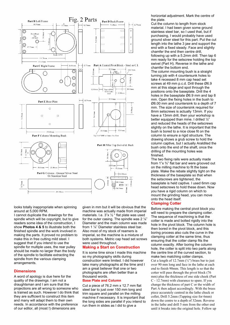
looks totally inappropriate when spinningaround at 5,000 RPM.I cannot duplicate the drawings for thespindle which will be copyright, but to givereaders some idea of the construction, Ishow Photos 4 & 5 to illustrate both thefinished spindle and the work involved inmaking the parts. It proved no problem tomake this in free cutting mild steel. Isuggest that if you intend to use thespindle for multiple uses, the rear pulleyshould be made no larger than the bodyof the spindle to facilitate extracting thespindle from the various clampingarrangements.
DimensionsA word of apology is due here for thequality of the drawings. I am not adraughtsman and I am sure that theprojections are all wrong to someone whois trained as such. However I do think thatthey are sufficient to construct this itemand many will adapt them to their ownneeds. In accordance with the preferenceof our editor, all (most !) dimensions are
given in mm but it will be obvious that themachine was actually made from imperialmaterials. I.e. 3”x ½ “ flat plate was usedfor the outer casing. The spindle was 2 ¼”Diameter and the main column was madefrom 1 ¼” Diameter stainless steel bar.Also most of my stock of reamers isimperial, so the machine is a mixture ofboth systems. Metric cap head set screwswere used throughout.Making a Start on ConstructionIt is some time since I made this machineso my photography skills duringconstruction were limited. I did howevertake many photographs at the time and Iam a great believer that one or twophotographs are often better than athousand words.Base Plate and ColumnCut a piece of 76.2 mm x 12.7 mm flatsteel bar to just over 150 mm long andtrim square and parallel on the millingmachine if necessary. It is important thatthe long sides are parallel if you intend torun them in slides as I did to give a
horizontal adjustment. Mark the centre ofthe plate.Cut the column to length from stockmaterial. I had been given some groundstainless steel bar, so I used that, but ifpurchasing, I would probably have usedground silver steel for this part. Put the cutlength into the lathe 3 jaw and support theend with a fixed steady. Face and slightlychamfer the end then centre drill,following up with a 5.2mm drill. Then tap 6mm ready for the setscrew holding the topswivel (Part H). Reverse in the lathe andchamfer the bottom end.The column mounting bush is a straightturning job with 4 countersunk holes totake 4 recessed 8 mm cap head setscrews at 49 mm p.c.d. Drill these Ø6.9mm at this stage and spot through thepositions onto the baseplate. Drill the 4holes in the baseplate Ø6.9 mm and tap 8mm. Open the fixing holes in the bush toØ8.00 mm and countersink to a depth of 7mm. The size of countersink required for8mm setscrews is actually 13mm. If youhave a 13mm drill, then your workshop isbetter equipped than mine. I drilled ½”and reduced the heads of the setscrewsslightly on the lathe. It is important that thebush is bored to a nice close fit on thecolumn to ensure a rigid structure. Thedrawing shows a grub screw to hold thecolumn captive, but I actually Araldited thebush onto the end of the shaft, once thedrilling of the mounting holes wasfinished.The two fixing rails were actually madefrom 1”x ¾” flat bar and were grooved outon the milling machine to fit the baseplate. Make the rebate slightly tight on thethickness of the baseplate so that whenthe setscrews are tightened, thebaseplate is held captive. I used 6mm caphead setscrews to hold these down. Nowyou have a rigid column on which tomount the grinding head, you can moveonto the head itself.Clamping CotterBefore making the central pivot block youwill need to prepare the clamping cotter.The sequence of machining is that thecotter is made and bolted rigidly into thehole in the pivot block. The column hole isthen bored in the pivot block, and thisboring process also cuts the curve in theclamping cotter at the same time, thusensuring that the cotter clamp fits thecolumn exactly. After boring the columnhole, the cotter is split into two parts alongthe centre line of the curved section, tomake two matching cotter clamps.Cut a length of 12.7mm (½”) brass bar to justover 90 mm long and face in the lathe at eachend to finish 90mm. This length is so that thecotter will pass through the pivot block (76mm) plus the thickness of one side cheek (PartC - 12.7mm) with clearance to spare. If youchange the thickness of part C or the width ofPart A then adjust accordingly. With the brasspiece accurately centred in the lathe chuck orcollet, Drill 5.2mm (Tapping size for 6mm)down the centre to a depth of 32mm. Reversein the lathe and drill 5 mm from the other enduntil it breaks into the original hole. Follow up
by drilling or reaming 6mm from this end to adepth of 58mm to give clearance for a 6mmbolt. Fit a large, strong, washer to the threadedend by means of a 6mm set screw whicheffectively puts a temporary “head” onto the
brass cotter. Put on one side until it can beinserted into the pivot block.
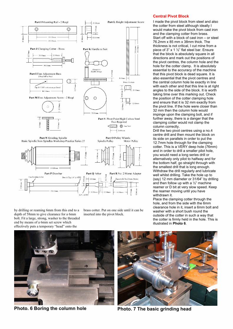
Central Pivot BlockI made the pivot block from steel and alsothe cotter from steel although ideally Iwould make the pivot block from cast ironand the clamping cotter from brass.Start off with a block of cast iron – or steel76.2mm x 85 mm x 38mm thick. Thethickness is not critical, I cut mine from apiece of 3” x 1 ½” flat steel bar. Ensurethat the block is absolutely square in alldirections and mark out the positions ofthe pivot centres, the column hole and thehole for the cotter clamp. It is absolutelyessential to the accuracy of the machinethat this pivot block is dead square. It isalso essential that the pivot centres andthe central column hole lie exactly in linewith each other and that this line is at rightangles to the side of the block. It is worthtaking time over this marking out. Checkthe position of the cotter clamping holeand ensure that it is 32 mm exactly fromthe pivot line. If the hole were closer than32 mm then the column hole wouldimpinge upon the clamping bolt, and iffurther away, there is a danger that theclamping cotter would not clamp thecolumn correctly.Drill the two pivot centres using a no.4centre drill and then mount the block onits side on parallels in order to put the12.7mm hole through for the clampingcotter. This is a VERY deep hole (76mm)and in order to drill a smaller pilot hole,you would need a long series drill oralternatively only pilot to halfway and forthe bottom half, go straight through withthe smallest drill that is long enough.Withdraw the drill regularly and lubricatewell whilst drilling. Take the hole up to(say) 12 mm diameter or 31/64” by drillingand then follow up with a ½” machinereamer or D bit at very slow speed. Keepthe reamer moving until you havewithdrawn it.Place the clamping cotter through thehole, and from the side with the 6mmclearance hole in it, insert a 6mm bolt andwasher with a short bush round theoutside of the cotter in such a way thatthe cotter is firmly held in the hole. This isillustrated in Photo 6.
Photo. 6 Boring the column hole Photo. 7 The basic grinding head
Place the block in the machine vice – orclamp to the milling machine table –tapping securely down on parallels as inPhoto 6. Start by drilling the column holethrough the block, using first a centre drilland then successively larger drills untilyou have reached either your largest drillor the capacity of your milling machine.Bore out until the hole is a nice CLOSE fiton the column. As you approach thefinished size, do take several passes atthe same setting to ensure that all thespring in the tool has been eliminated. Asthe work progresses, you will be able tosee, and indeed hear the change in noteas the boring operation cuts into the brasscotter. You can just see this in the photo,although my cotter was steel. If the boringoperation breaks into the central hole inthe cotter and touches the bolt, then youhave got your measurements wrong orone of the holes is not at right angles.Once you have finished this hole, youmay, at this point, also drill and tap thehole through the block which will act as anut on the main head raising lead screw(Part L). Move the table 23mm (to the leftin the photo) and drill through the block atthe tapping size for the thread of the headraising screw. I used 5/16 “ BSF for thisand drilled 6.9 mm, but fully metricengineers will probably prefer to use an 8mm x 1.25 thread and drill 6.9 mm. Thethread is unimportant, but a fairly finethread gives a nice slow adjustment of thehead on the column.Finally mill the rebate on the block, turnover and mill the rebate on the other side.The dimensions of these are notparticularly critical, so long as the fineadjustment screws can eventually bear onthe central portion. To see the basiclayout, see Photo.12. In this photo youcan see the two fine adjustment bars withthe rebated part of the block visiblebetween them.In use, there is not much clearancebetween the back of this block and theback of the outer casing pivoting round it(Part D). This can mean that the back ofthe block can foul the back of the pivotingcasing when substantially raising orlowering the grinding head using the fine
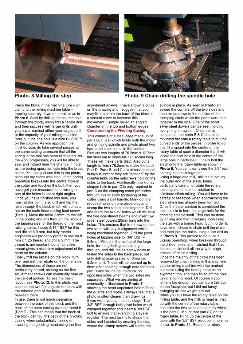
adjustment screws. I have shown a curveon the drawing and I suggest that youmay like to curve the back of the block ina vertical curve to increase thismovement. I simply milled an angledchamfer on the top and bottom edges.Constructing the Pivoting CasingThis consists of a steel cage made up ofparts B, C & D which holds both the motorand grinding spindle and pivots about twohardened steel points in the centre.First cut two lengths of 76.2mm x 12.7mmflat steel bar to finish full 171.45mm long.These will make parts B&C. Also cut alength to finish 76.2mm to make the backPart D. Parts B and C are almost identicalin layout, except they are “handed” by thecountersinks on the setscrews holding thesides to the back. Additionally, the kidneyshaped hole in part C is only required inpart C as the clamping cotter protrudesthrough this to allow tightening of thecotter using a ball handle. Mark out therequired holes on one piece only andclamp the two side pieces together. Drilland ream the two ½” holes which will holdthe fine adjustment beams and insert twosilver steel dowels 20mm long into theholes. This ensures that from now on thetwo sides will stay in alignment whilstbeing machined together. Drill the pivotholes at tapping size for 3/8” BSF –8.4mm. Pilot drill the centre of the largehole, for the grinding spindle, rightthrough, and drill the setscrew holes tofasten the sides to the back piece, butonly drill at tapping size for 6mm i.e.5.2mm drill. These will be opened up to6mm after spotting through onto the backpart D and will be countersunk onopposing sides when the two sides areseparated. What we are aiming ateventually is illustrated in Photo 7showing the head unpainted before fittingthe guards and motor. I always feel that aphoto is often clearer than drawings.If you wish, you can, at this stage, Tap3/8” BSF through both pivot holes whilstclamped together and insert a 3/8 BSFbolt to ensure that everything stays inregister. The next task is to shape thesides and I started by creating the stepwhere the clamp screws will clamp the
spindle in place. As seen in Photo 8 Isawed the corners off the two sides andthen milled down to the outside of theclamping circle whilst the parts were heldtogether in the vice. One of the shortsilver steel dowels can be seen holdingeverything in register. Once this iscompleted, the parts B & C should bemounted flat onto a rotary table to cut thecurved ends of the pieces. In order to dothis, fit a spigot into the centre of therotary table of such a diameter that it willlocate the pilot hole in the centre of thelarge hole in parts B&C. Finally bolt thestack onto the rotary table as shown inPhoto 9. You can clearly see the 3/8” boltholding the stack together.Using a large end mill, mill the curve onthe outer end of the stack, beingparticularly careful to rotate the rotarytable against the cutter rotation toeliminate climb milling. You will have to becareful or set stops when approaching thestep which has already been formed.Once the outer contour is completed thenext task is to bore the large hole for thegrinding spindle itself. This can be doneby drilling and then gradually increasingthe size with a boring head, but in order tosave time I chose to chain drill the circleand then join the holes using a slot drill asin Photo 9. This proved to be quite avicious operation, when breaking throughthe drilled holes, and I wished that I hadchosen to slot drill all the way through,instead of chain drilling.Once the majority of the circle has beenremoved by chain drilling in this way, lineup the milling machine with the markedout circle using the boring head as analignment tool and then finish off the holeusing a boring head. Of course if yourlathe is big enough you can bore this outon the faceplate, but I did not fancyswinging all that weight around.While you still have the rotary table on themilling table, and the milling head is linedup with the centre of the rotary table,separate the two sides and identify whichis the part C. Mount that part (C) on therotary table, lining up the centre of thetable with the 3/8” BSF pivot point hole, asshown in Photo 11. Rotate the rotary
Photo. 8 Milling the step Photo. 9 Chain drilling the spindle hole
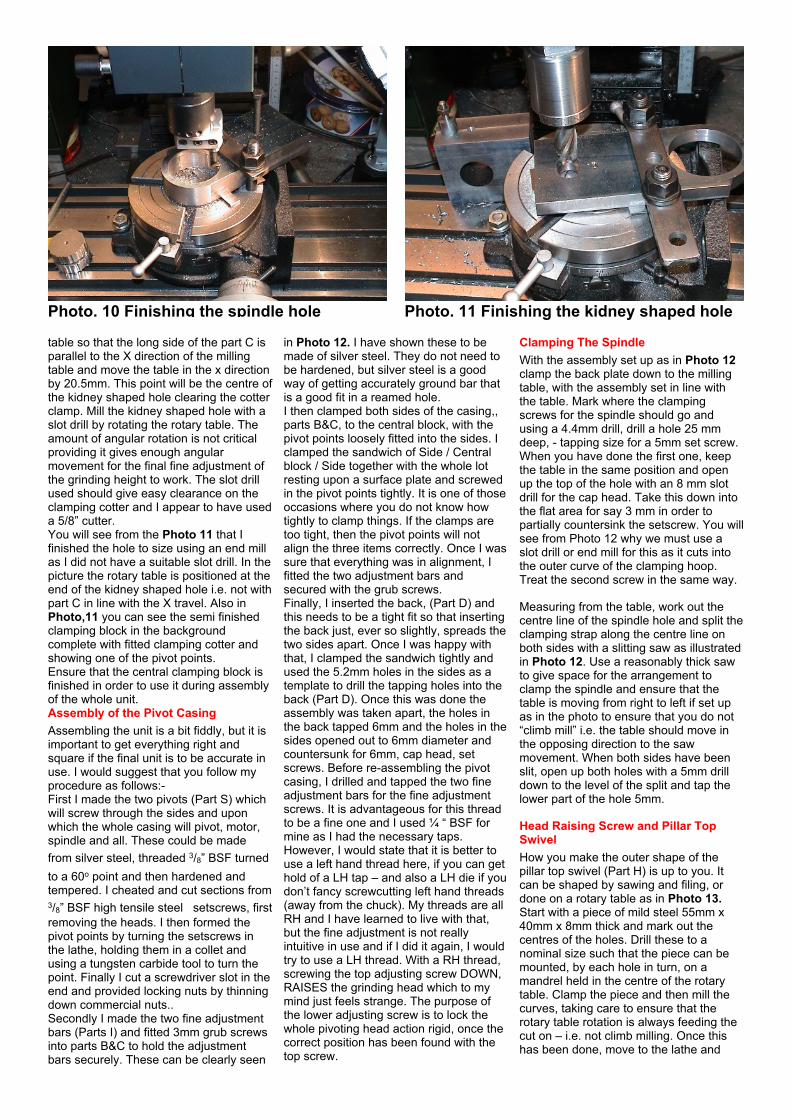
table so that the long side of the part C isparallel to the X direction of the millingtable and move the table in the x directionby 20.5mm. This point will be the centre ofthe kidney shaped hole clearing the cotterclamp. Mill the kidney shaped hole with aslot drill by rotating the rotary table. Theamount of angular rotation is not criticalproviding it gives enough angularmovement for the final fine adjustment ofthe grinding height to work. The slot drillused should give easy clearance on theclamping cotter and I appear to have useda 5/8” cutter.You will see from the Photo 11 that Ifinished the hole to size using an end millas I did not have a suitable slot drill. In thepicture the rotary table is positioned at theend of the kidney shaped hole i.e. not withpart C in line with the X travel. Also inPhoto,11 you can see the semi finishedclamping block in the backgroundcomplete with fitted clamping cotter andshowing one of the pivot points.Ensure that the central clamping block isfinished in order to use it during assemblyof the whole unit.Assembly of the Pivot CasingAssembling the unit is a bit fiddly, but it isimportant to get everything right andsquare if the final unit is to be accurate inuse. I would suggest that you follow myprocedure as follows:-First I made the two pivots (Part S) whichwill screw through the sides and uponwhich the whole casing will pivot, motor,spindle and all. These could be madefrom silver steel, threaded 3/8” BSF turnedto a 60o point and then hardened andtempered. I cheated and cut sections from3/8” BSF high tensile steel setscrews, firstremoving the heads. I then formed thepivot points by turning the setscrews inthe lathe, holding them in a collet andusing a tungsten carbide tool to turn thepoint. Finally I cut a screwdriver slot in theend and provided locking nuts by thinningdown commercial nuts..Secondly I made the two fine adjustmentbars (Parts I) and fitted 3mm grub screwsinto parts B&C to hold the adjustmentbars securely. These can be clearly seen
in Photo 12. I have shown these to bemade of silver steel. They do not need tobe hardened, but silver steel is a goodway of getting accurately ground bar thatis a good fit in a reamed hole.I then clamped both sides of the casing,,parts B&C, to the central block, with thepivot points loosely fitted into the sides. Iclamped the sandwich of Side / Centralblock / Side together with the whole lotresting upon a surface plate and screwedin the pivot points tightly. It is one of thoseoccasions where you do not know howtightly to clamp things. If the clamps aretoo tight, then the pivot points will notalign the three items correctly. Once I wassure that everything was in alignment, Ifitted the two adjustment bars andsecured with the grub screws.Finally, I inserted the back, (Part D) andthis needs to be a tight fit so that insertingthe back just, ever so slightly, spreads thetwo sides apart. Once I was happy withthat, I clamped the sandwich tightly andused the 5.2mm holes in the sides as atemplate to drill the tapping holes into theback (Part D). Once this was done theassembly was taken apart, the holes inthe back tapped 6mm and the holes in thesides opened out to 6mm diameter andcountersunk for 6mm, cap head, setscrews. Before re-assembling the pivotcasing, I drilled and tapped the two fineadjustment bars for the fine adjustmentscrews. It is advantageous for this threadto be a fine one and I used ¼ “ BSF formine as I had the necessary taps.However, I would state that it is better touse a left hand thread here, if you can gethold of a LH tap – and also a LH die if youdon’t fancy screwcutting left hand threads(away from the chuck). My threads are allRH and I have learned to live with that,but the fine adjustment is not reallyintuitive in use and if I did it again, I wouldtry to use a LH thread. With a RH thread,screwing the top adjusting screw DOWN,RAISES the grinding head which to mymind just feels strange. The purpose ofthe lower adjusting screw is to lock thewhole pivoting head action rigid, once thecorrect position has been found with thetop screw.
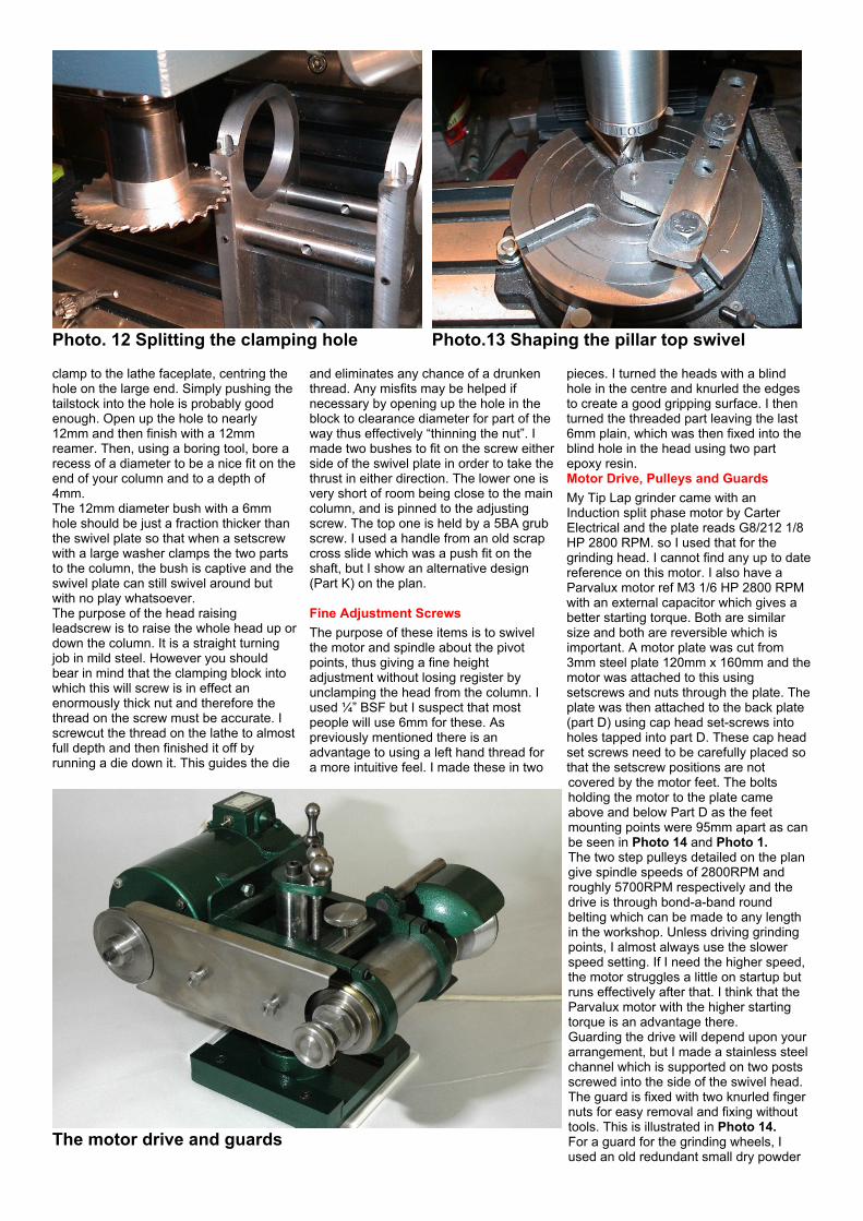
Clamping The SpindleWith the assembly set up as in Photo 12clamp the back plate down to the millingtable, with the assembly set in line withthe table. Mark where the clampingscrews for the spindle should go andusing a 4.4mm drill, drill a hole 25 mmdeep, - tapping size for a 5mm set screw.When you have done the first one, keepthe table in the same position and openup the top of the hole with an 8 mm slotdrill for the cap head. Take this down intothe flat area for say 3 mm in order topartially countersink the setscrew. You willsee from Photo 12 why we must use aslot drill or end mill for this as it cuts intothe outer curve of the clamping hoop.Treat the second screw in the same way.
Measuring from the table, work out thecentre line of the spindle hole and split theclamping strap along the centre line onboth sides with a slitting saw as illustratedin Photo 12. Use a reasonably thick sawto give space for the arrangement toclamp the spindle and ensure that thetable is moving from right to left if set upas in the photo to ensure that you do not“climb mill” i.e. the table should move inthe opposing direction to the sawmovement. When both sides have beenslit, open up both holes with a 5mm drilldown to the level of the split and tap thelower part of the hole 5mm.
Head Raising Screw and Pillar TopSwivelHow you make the outer shape of thepillar top swivel (Part H) is up to you. Itcan be shaped by sawing and filing, ordone on a rotary table as in Photo 13.Start with a piece of mild steel 55mm x40mm x 8mm thick and mark out thecentres of the holes. Drill these to anominal size such that the piece can bemounted, by each hole in turn, on amandrel held in the centre of the rotarytable. Clamp the piece and then mill thecurves, taking care to ensure that therotary table rotation is always feeding thecut on – i.e. not climb milling. Once thishas been done, move to the lathe and
Photo. 10 Finishing the spindle hole Photo. 11 Finishing the kidney shaped hole
clamp to the lathe faceplate, centring thehole on the large end. Simply pushing thetailstock into the hole is probably goodenough. Open up the hole to nearly12mm and then finish with a 12mmreamer. Then, using a boring tool, bore arecess of a diameter to be a nice fit on theend of your column and to a depth of4mm.The 12mm diameter bush with a 6mmhole should be just a fraction thicker thanthe swivel plate so that when a setscrewwith a large washer clamps the two partsto the column, the bush is captive and theswivel plate can still swivel around butwith no play whatsoever.The purpose of the head raisingleadscrew is to raise the whole head up ordown the column. It is a straight turningjob in mild steel. However you shouldbear in mind that the clamping block intowhich this will screw is in effect anenormously thick nut and therefore thethread on the screw must be accurate. Iscrewcut the thread on the lathe to almostfull depth and then finished it off byrunning a die down it. This guides the die
and eliminates any chance of a drunkenthread. Any misfits may be helped ifnecessary by opening up the hole in theblock to clearance diameter for part of theway thus effectively “thinning the nut”. Imade two bushes to fit on the screw eitherside of the swivel plate in order to take thethrust in either direction. The lower one isvery short of room being close to the maincolumn, and is pinned to the adjustingscrew. The top one is held by a 5BA grubscrew. I used a handle from an old scrapcross slide which was a push fit on theshaft, but I show an alternative design(Part K) on the plan.
Fine Adjustment ScrewsThe purpose of these items is to swivelthe motor and spindle about the pivotpoints, thus giving a fine heightadjustment without losing register byunclamping the head from the column. Iused ¼” BSF but I suspect that mostpeople will use 6mm for these. Aspreviously mentioned there is anadvantage to using a left hand thread fora more intuitive feel. I made these in two
pieces. I turned the heads with a blindhole in the centre and knurled the edgesto create a good gripping surface. I thenturned the threaded part leaving the last6mm plain, which was then fixed into theblind hole in the head using two partepoxy resin.Motor Drive, Pulleys and GuardsMy Tip Lap grinder came with anInduction split phase motor by CarterElectrical and the plate reads G8/212 1/8HP 2800 RPM. so I used that for thegrinding head. I cannot find any up to datereference on this motor. I also have aParvalux motor ref M3 1/6 HP 2800 RPMwith an external capacitor which gives abetter starting torque. Both are similarsize and both are reversible which isimportant. A motor plate was cut from3mm steel plate 120mm x 160mm and themotor was attached to this usingsetscrews and nuts through the plate. Theplate was then attached to the back plate(part D) using cap head set-screws intoholes tapped into part D. These cap headset screws need to be carefully placed sothat the setscrew positions are notcovered by the motor feet. The boltsholding the motor to the plate cameabove and below Part D as the feetmounting points were 95mm apart as canbe seen in Photo 14 and Photo 1.The two step pulleys detailed on the plangive spindle speeds of 2800RPM androughly 5700RPM respectively and thedrive is through bond-a-band roundbelting which can be made to any lengthin the workshop. Unless driving grindingpoints, I almost always use the slowerspeed setting. If I need the higher speed,the motor struggles a little on startup butruns effectively after that. I think that theParvalux motor with the higher startingtorque is an advantage there.Guarding the drive will depend upon yourarrangement, but I made a stainless steelchannel which is supported on two postsscrewed into the side of the swivel head.The guard is fixed with two knurled fingernuts for easy removal and fixing withouttools. This is illustrated in Photo 14.For a guard for the grinding wheels, Iused an old redundant small dry powder
Photo. 12 Splitting the clamping hole Photo.13 Shaping the pillar top swivel
The motor drive and guards
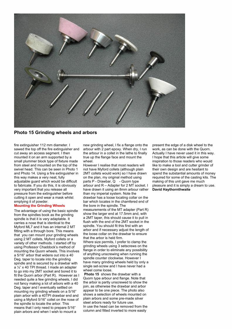
fire extinguisher 112 mm diameter. Isawed the top off the fire extinguisher andcut away an access segment. I thenmounted it on an arm supported by asmall plummer block type of fixture madefrom steel and mounted on the top of theswivel head. This can be seen in Photo 1and Photo 14. Using a fire extinguisher inthis way makes a very neat, fullyadjustable guard which would be difficultto fabricate. If you do this, it is obviouslyvery important that you release allpressure from the extinguisher beforecutting it open and wear a mask whilstemptying it of powder.Mounting the Grinding WheelsThe advantage of using the basic spindlefrom the spindles book as the grindingspindle is that it is very adaptable. Itcarries a nose that is identical to theMyford ML7 and it has an internal 2 MTfitting with a through bore. This meansthat you can mount your grinding wheelsusing 2 MT collets, Myford collets or avariety of other methods. I started off byusing Professor Chaddock’s method ofmounting the Quorn wheels. This involvesa 5/16” arbor that widens out into a 40Deg. taper to locate into the grindingspindle and is secured by a drawbar witha ¼” x 40 TPI thread. I made an adapterto go into my 2MT socket and bored it tofit the Quorn arbor (Part R). However as Ineeded quite a few grinding wheels, I didnot fancy making a lot of arbors with a 40Deg. taper and I eventually settled onmounting my grinding wheels on a 5/16”plain arbor with a 40TPI drawbar end andusing a Myford 5/16” collet on the nose ofthe spindle to locate the arbor. Thismeans that I only need to prepare 5/16”plain arbors and when I wish to mount a
new grinding wheel, I fix a flange onto thearbour with 2 part epoxy. When dry, I runthe arbour in a collet in the lathe to finallytrue up the flange face and mount thewheel.However I realise that most readers willnot have Myford collets (although plain2MT collets would work) so I have drawnon the plan, my original method usingparts P - Drawbar, Q - Quorn typearbour and R – Adapter for 2 MT socket. Ihave drawn it using an 8mm arbour ratherthan my imperial system. Note thedrawbar has a loose locating collar on thebar which locates in the chamfered end ofthe bore in the spindle. Themeasurements of the MT adapter (Part R)show the larger end at 17.5mm and, witha 2MT taper, this should cause it to pull inflush with the end of the 2MT socket in thespindle. You should fit this first with anarbor and if necessary adjust the length ofthe loose collar on the drawbar to ensurethat the arbor is held firm.Where size permits, I prefer to clamp thegrinding wheels using 3 setscrews on theflange in order to eliminate any possibilityof anything unscrewing when running thespindle counter clockwise. However Ihave many grinding wheels held by only asingle set-screw and I have never had awheel come loose.Photo 15 shows the drawbar with aQuorn type arbour and flange. Note thatthe arbor is partly unscrewed to show thejoin, as otherwise the drawbar and arborappear to be one piece. The photo alsoshows a selection of wheels mounted onplain arbors and some pre-made silversteel arbors ready for future use.In use the head can be removed from thecolumn and fitted inverted to more easily
present the edge of a disk wheel to thework, as can be done with the Quorn.Actually I have never used it in this way.I hope that this article will give someinspiration to those readers who wouldlike to make a tool and cutter grinder oftheir own design and are hesitant tospend the substantial amounts of moneyrequired for some of the casting kits. Themaking of this unit gave me muchpleasure and it is simply a dream to use.David Haythornthwaite
Photo 15 Grinding wheels and arbors


![H-1030 TUB GRINDER - Haybuster · H-1030 TUB GRINDER [ PTO tub grinder ] The latest tub grinder from the hay grinding experts. Haybuster has been in the Hay Grinding business for](https://img.pdfslide.us/doc/110x75/5c0c779309d3f252498c3035/h-1030-tub-grinder-h-1030-tub-grinder-pto-tub-grinder-the-latest-tub-grinder.jpg)