Embed Size (px)
Citation preview
1
This book consists of two manuals:
The OPERATORS MANUAL which contains all theinformation on operating and doing routine dailymaintenance on this equipment.
The ASSEMBLY and SERVICE MANUAL which isused by the maintainence department to install theequipment and to do all maintenance except routinedaily maintenance.
Setting the Standard With theWorld's Most Valued Grinders.
ACCU-PR0 632SPIN RELIEF
GRINDER

2
WWWWWe are are are are are committed to:e committed to:e committed to:e committed to:e committed to:
Providing superior customer support, training,and service.
Manufacturing the highest quality products at anunequaled value.
Setting the industry standard by investing intechnological product innovation.
Manufacturing products specifically designed tomaintain original equipment manufacturers'specifications.
Interacting with and supporting all originalequipment manufacturers.
Setting the Standard With the World's Most Valued Grinders.
3
ACCU-PR0 632SPIN RELIEF
GRINDER
OPERATORSMANUAL
6327953 (11-05)
4
The Caution Symbol identifies special in-structions or procedures which, if notstrictly observed, could result in damageto or destruction of equipment.
The Warning Symbol identifiesspecial instructions or procedureswhich, if not correctly followed,could result in personal injury.
Safety Awareness Symbols are insertedinto this manual to alert you to possibleSafety Hazards. Whenever you see thesesymbols, follow their instructions.
1. KEEP GUARDS IN PLACE and in workingorder.
2. REMOVE WRENCHES AND OTHERTOOLS.
3. KEEP WORK AREA CLEAN.
4. DON'T USE IN DANGEROUS ENVIRONMENT.Don't use Grinder in damp or wet locations.
Machine is for indoor use only. Keep work areawell lit.
5. KEEP ALL VISITORS AWAY. All visitorsshould be kept a safe distance from work area.
6. MAKE WORK AREA CHILD-PROOF withpadlocks or master switches.
7. DON'T FORCE THE GRINDER. It will do the jobbetter and safer if used as specified in thismanual.
8. USE THE RIGHT TOOL. Don't force the grinderor an attachment to do a job for which it was notdesigned.
9. WEAR PROPER APPAREL. Wear no loose clothing, gloves, neckties, or jewelry which mayget caught in moving parts. Nonslip footwear isrecommended. Wear protective hair covering tocontain long hair.
10. ALWAYS USE SAFETY GLASSES.
11. SECURE YOUR WORK. Make certain that thecutting unit is securely fastened with the clampsprovided before operating.
12. DON'T OVERREACH. Keep proper footing andbalance at all times.
13. MAINTAIN GRINDER WITH CARE. Followinstructions in Service Manual for lubrication andpreventive maintenance.
14. DISCONNECT POWER BEFORE SERVICING,or when changing the grinding wheel.
15. REDUCE THE RISK OF UNINTENTIONALSTARTING. Make sure the switch is OFF beforeplugging in the grinder.
16. USE RECOMMENDED ACCESSORIES. Consultthe manual for recommended accessories. Usingimproper accessories may cause risk of personalinjury.
17. CHECK DAMAGED PARTS. A guard or otherpart that is damaged or will not perform itsintended function should be properly repaired orreplaced.
18. KNOW YOUR EQUIPMENT. Read this manualcarefully. Learn its application and limitations aswell as specific potential hazards.
19. KEEP ALL SAFETY DECALS CLEAN ANDLEGIBLE. If safety decals become damaged orillegible for any reason, replace immediately.Refer to replacement parts illustrations in ServiceManual for the proper location and part numbersof safety decals.
20. DO NOT OPERATE THE GRINDER WHENUNDER THE INFLUENCE OF DRUGS,ALCOHOL, OR MEDICATION.
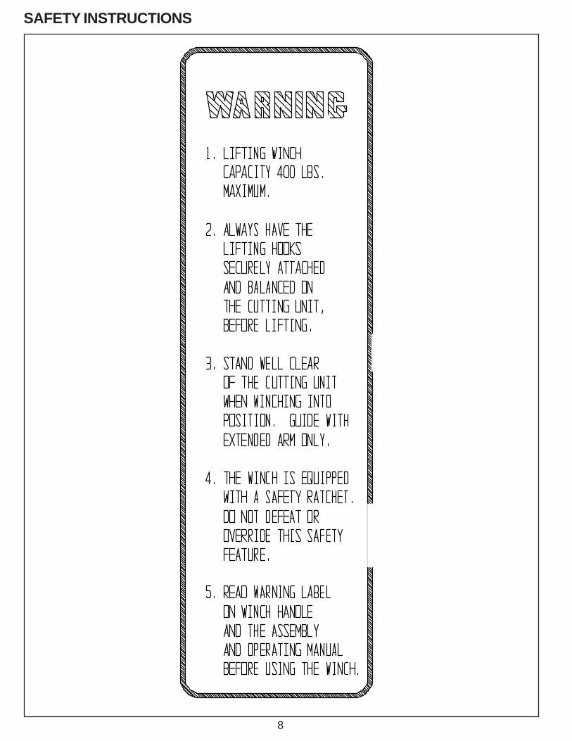
SAFETY INSTRUCTIONS
5
SAFETY INSTRUCTIONS
IMPROPER USE OF GRINDING WHEEL MAY CAUSEBREAKAGE AND SERIOUS INJURY.
Grinding is a safe operation if the few basic rules listed below are followed. These rules are based on materialcontained in the ANSI B7.1 Safety Code for "Use, Care and Protection of Abrasive Wheels". For your safety,we suggest you benefit from the experience of others and follow these rules.
DO
1. DO always HANDLE AND STOREwheels in a careful manner.
2. DO VISUALLY INSPECT all wheels beforemounting for possible damage.
3. DO CHECK MACHINE SPEED against theestablished maximum safe operating speedmarked on wheel.
4. DO CHECK MOUNTING FLANGES for equaland correct diameter.
5. DO USE MOUNTING BLOTTERS when suppliedwith wheels.
6. DO be sure WORK REST is properlyadjusted.
7. DO always USE A SAFETY GUARD COVERINGat least one-half of the grinding wheel.
8. DO allow NEWLY MOUNTED WHEELS to run atoperating speed, with guard in place, for at leastone minute before grinding.
9. DO always WEAR SAFETY GLASSES or sometype of eye protection when grinding.
DON'T
1. DON'T use a cracked wheel or one that HAS BEENDROPPED or has become damaged.
2. DON'T FORCE a wheel onto the machine ORALTER the size of the mounting hole--if wheel won'tfit the machine, get one that will.
3. DON'T ever EXCEED MAXIMUM OPERATINGSPEED established for the wheel.
4. DON'T use mounting flanges on which the bearingsurfaces ARE NOT CLEAN, FLAT AND FREE OFBURRS.
5. DON'T TIGHTEN the mounting nut EXCESSIVELY.
6. DON'T grind on the SIDE OF THE WHEEL (seeSafety Code B7.2 for exception).
7. DON'T start the machine until the WHEEL GUARDIS IN PLACE.
8. DON'T JAM work into the wheel.
9. DON'T STAND DIRECTLY IN FRONT of agrinding wheel whenever a grinder is started.
10. DON'T FORCE GRINDING so that motor slowsnoticeably or work gets hot.
AVOID INHALATION OF DUST generated by grinding and cutting operations. Exposureto dust may cause respiratory ailments. Use approved NIOSH or MSHA respirators, safetyglasses or face shields, and protective clothing. Provide adequate ventilation to eliminatedust, or to maintain dust level below the Threshold Limit Value for nuisance dust asclassified by OSHA.
6
TABLE OF CONTENTS
This machine is intended for grinding the reel of reel type mower unitsONLY. Any use other than this may cause personal injury and void thewarranty.
To assure the quality and safety of your machine and to maintain thewarranty, you MUST use original equipment manufactures replacementparts and have any repair work done by a qualified professional.
ALL operators of this equipment must be thoroughly trained BEFOREoperating the equipment.
Do not use compressed air to clean grinding dust from the machine. Thisdust can cause personal injury as well as damage to the grinder. Machineis for indoor use only. Do not use a power washer to clean the machine.
CONTENTSDaily Maintenance ..................................................................................................................... Page 6Safety Warnings ........................................................................................................................ Page 4-8Specifications ............................................................................................................................ Page 9Getting to Know Your Grinder .................................................................................................... Page 10-16Operating Instructions ............................................................................................................... Page 17-30Reel Setup Chart ....................................................................................................................... Page 32
DAILY MAINTENANCE BY THE OPERATOROn a daily basis, clean the machine by wiping it off.On a daily basis, remove all grinding grit from the grinding head and bellows area.On a daily basis, inspect the machine for loose fasteners or components.Contact your company's Maintenance Department if damaged or defective parts are found.
DO NOT USE COMPRESSED AIR TO CLEANGRINDING DUST FROM GRINDER.
The grinder is equipped with a low voltage relay whichis factory preset at 100 VAC. If the power supply linedoes not deliver 100 VAC power under load, the relaywill open and trip out the starter. If this occurs, yourpower supply line is inadequate and must be correctbefore proceeding further with the grinder.
Low Voltage Relay
7
SAFETY INSTRUCTIONS
PLEASE TAKE SPECIAL NOTE OF THE FOLLOWING WARNING DECALSLOCATED ON THE FRONT OF THE GRINDER, THE WINCH BOOM OR LIFTAND THE FRONT TOOLING BAR OF THE ACCU-Pro 632
Symbol to keep exposed gasolineor flammables away from thegrinder because it operates with alarge amount of sparks.
Symbol for maximum weightcapacity for winch/Lift
Symbol for Read operatorsmanual, wear safetyglasses and disconnectpower before servicing.
Symbol for caution relating to RPMof the motor and minimum saferated RPM of the grinding wheel.
Symbol to keep visitors a safedistance away from the grinder.
Symbol for hot surface which couldcause burns.
Symbol identifying a panel, cover,or area as having live electricalcomponents within.
Symbol for sharp object which willcause serious injury.
Symbol that operators and peoplein the close proximity must wearrespirators or have adequateventilation systems.
Symbol for hearingprotection required whenoperating this machine
8
SAFETY INSTRUCTIONS
9
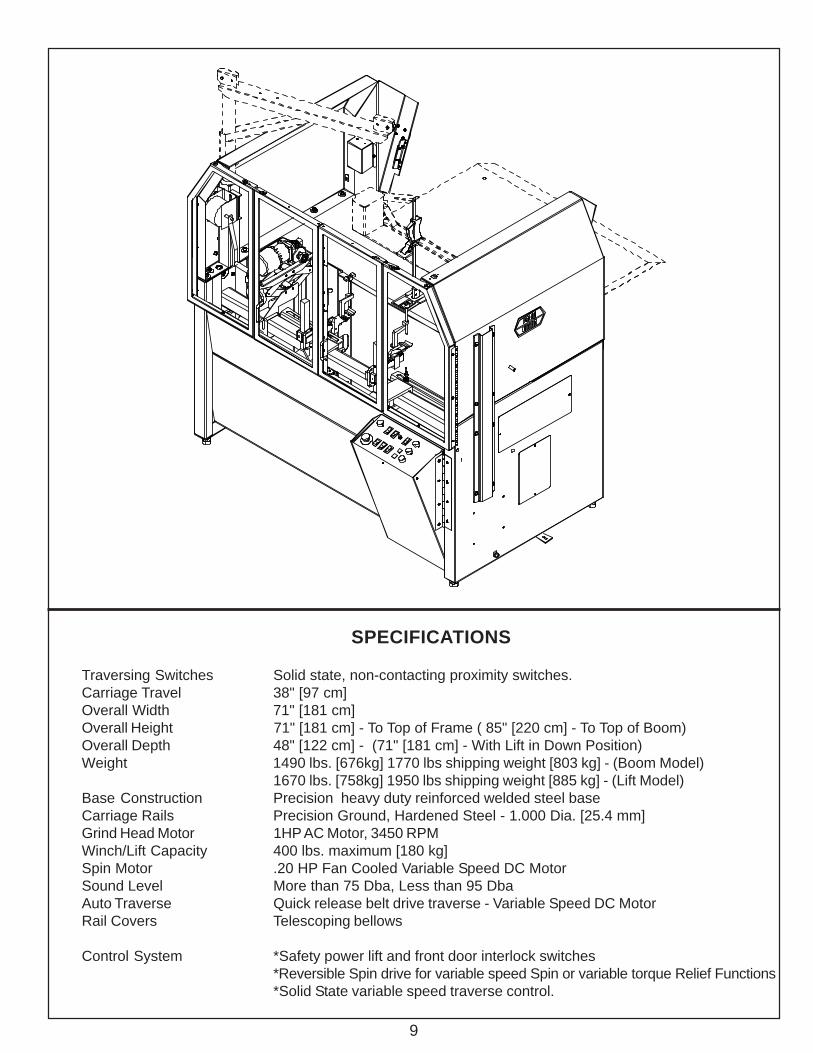
SPECIFICATIONS
Traversing Switches Solid state, non-contacting proximity switches.Carriage Travel 38" [97 cm]Overall Width 71" [181 cm]Overall Height 71" [181 cm] - To Top of Frame ( 85" [220 cm] - To Top of Boom)Overall Depth 48" [122 cm] - (71" [181 cm] - With Lift in Down Position)Weight 1490 lbs. [676kg] 1770 lbs shipping weight [803 kg] - (Boom Model)
1670 lbs. [758kg] 1950 lbs shipping weight [885 kg] - (Lift Model)Base Construction Precision heavy duty reinforced welded steel baseCarriage Rails Precision Ground, Hardened Steel - 1.000 Dia. [25.4 mm]Grind Head Motor 1HP AC Motor, 3450 RPMWinch/Lift Capacity 400 lbs. maximum [180 kg]Spin Motor .20 HP Fan Cooled Variable Speed DC MotorSound Level More than 75 Dba, Less than 95 DbaAuto Traverse Quick release belt drive traverse - Variable Speed DC MotorRail Covers Telescoping bellows
Control System *Safety power lift and front door interlock switches*Reversible Spin drive for variable speed Spin or variable torque Relief Functions*Solid State variable speed traverse control.
10
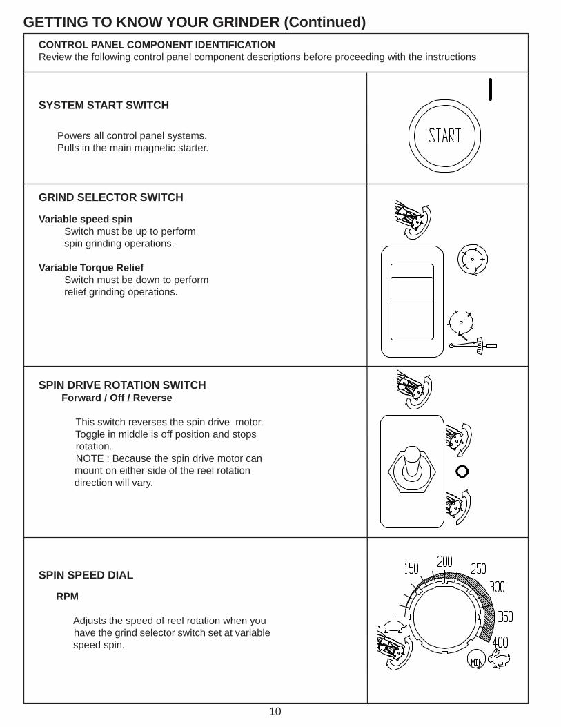
GETTING TO KNOW YOUR GRINDER (Continued)
RPM
Adjusts the speed of reel rotation when you have the grind selector switch set at variable speed spin.
SPIN SPEED DIAL
SPIN DRIVE ROTATION SWITCH Forward / Off / Reverse
This switch reverses the spin drive motor. Toggle in middle is off position and stops rotation. NOTE : Because the spin drive motor can
mount on either side of the reel rotation direction will vary.
GRIND SELECTOR SWITCH
Variable speed spin Switch must be up to perform spin grinding operations.
Variable Torque Relief Switch must be down to perform relief grinding operations.
Powers all control panel systems.Pulls in the main magnetic starter.
SYSTEM START SWITCH
CONTROL PANEL COMPONENT IDENTIFICATIONReview the following control panel component descriptions before proceeding with the instructions
11
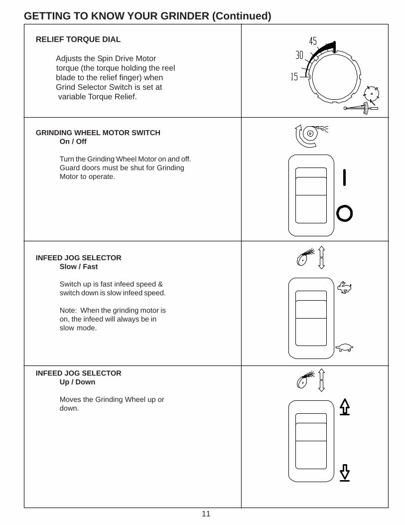
GETTING TO KNOW YOUR GRINDER (Continued)
RELIEF TORQUE DIAL
Adjusts the Spin Drive Motor torque (the torque holding the reel blade to the relief finger) when Grind Selector Switch is set at
variable Torque Relief.
GRINDING WHEEL MOTOR SWITCHOn / Off
Turn the Grinding Wheel Motor on and off.Guard doors must be shut for GrindingMotor to operate.
INFEED JOG SELECTORSlow / Fast
Switch up is fast infeed speed &switch down is slow infeed speed.
Note: When the grinding motor ison, the infeed will always be inslow mode.
INFEED JOG SELECTORUp / Down
Moves the Grinding Wheel up ordown.
12
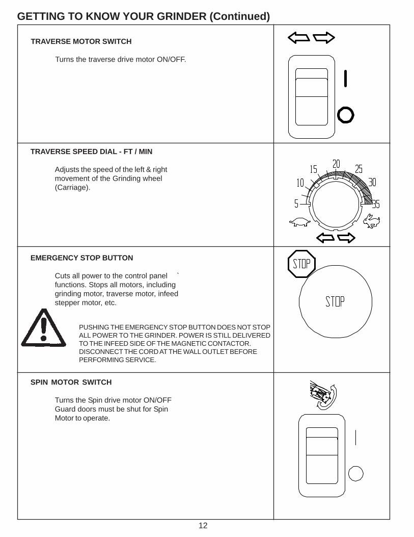
GETTING TO KNOW YOUR GRINDER (Continued)
TRAVERSE MOTOR SWITCH
Turns the traverse drive motor ON/OFF.
TRAVERSE SPEED DIAL - FT / MIN
Adjusts the speed of the left & rightmovement of the Grinding wheel(Carriage).
EMERGENCY STOP BUTTON
Cuts all power to the control panel `functions. Stops all motors, includinggrinding motor, traverse motor, infeedstepper motor, etc.
PUSHING THE EMERGENCY STOP BUTTON DOES NOT STOPALL POWER TO THE GRINDER. POWER IS STILL DELIVEREDTO THE INFEED SIDE OF THE MAGNETIC CONTACTOR.DISCONNECT THE CORD AT THE WALL OUTLET BEFOREPERFORMING SERVICE.
SPIN MOTOR SWITCH
Turns the Spin drive motor ON/OFFGuard doors must be shut for SpinMotor to operate.
13
GETTING TO KNOW YOUR GRINDER (Continued)
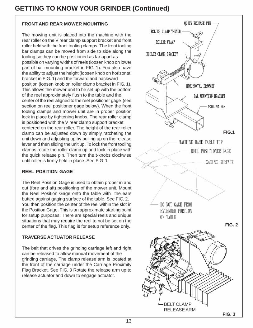
FRONT AND REAR MOWER MOUNTING
The mowing unit is placed into the machine with therear roller on the V rear clamp support bracket and frontroller held with the front tooling clamps. The front toolingbar clamps can be moved from side to side along thetooling so they can be positioned as far apart aspossible on varying widths of reels (loosen knob on lowerpart of bar mounting bracket in FIG. 1). You also havethe ability to adjust the height (loosen knob on horizontalbracket in FIG. 1) and the forward and backwardposition (loosen knob on roller clamp bracket in FIG. 1).This allows the mower unit to be set up with the bottomof the reel approximately flush to the table and thecenter of the reel aligned to the reel positioner gage (seesection on reel positioner gage below). When the fronttooling clamps and mower unit are in proper positionlock in place by tightening knobs. The rear roller clampis positioned with the V rear clamp support bracketcentered on the rear roller. The height of the rear rollerclamp can be adjusted down by simply ratcheting theunit down and adjusting up by pulling up on the releaselever and then sliding the unit up. To lock the front toolingclamps rotate the roller clamp up and lock in place withthe quick release pin. Then turn the t-knobs clockwiseuntil roller is firmly held in place. See FIG. 1.
REEL POSITION GAGE
The Reel Position Gage is used to obtain proper in andout (fore and aft) positioning of the mower unit. Mountthe Reel Position Gage onto the table with the earsbutted against gaging surface of the table. See FIG. 2.You then position the center of the reel within the slot inthe Position Gage. This is an approximate starting pointfor setup purposes. There are special reels and uniquesituations that may require the reel to not be set on thecenter of the flag. This flag is for setup reference only.
TRAVERSE ACTUATOR RELEASE
The belt that drives the grinding carriage left and rightcan be released to allow manual movement of thegrinding carriage. The clamp release arm is located atthe front of the carriage under the Carriage ProximityFlag Bracket. See FIG. 3 Rotate the release arm up torelease actuator and down to engage actuator.
FIG. 3
FIG.1
FIG. 2
BELT CLAMPRELEASE ARM
14
GETTING TO KNOW YOUR GRINDER (Continued)
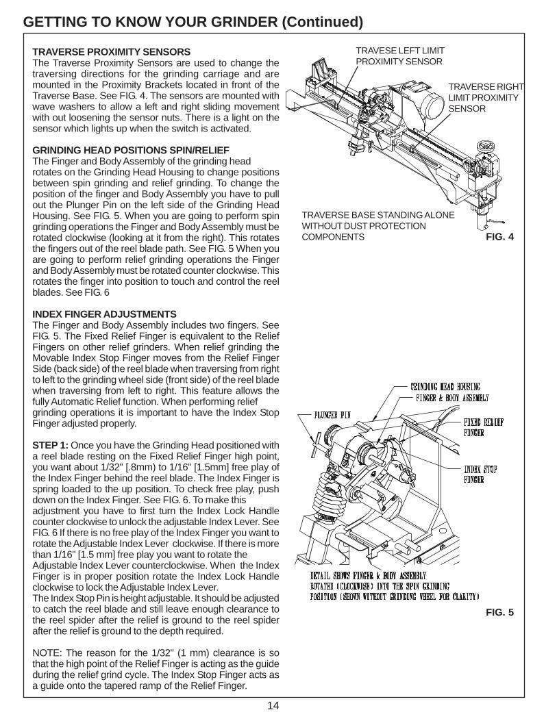
TRAVERSE PROXIMITY SENSORSThe Traverse Proximity Sensors are used to change thetraversing directions for the grinding carriage and aremounted in the Proximity Brackets located in front of theTraverse Base. See FIG. 4. The sensors are mounted withwave washers to allow a left and right sliding movementwith out loosening the sensor nuts. There is a light on thesensor which lights up when the switch is activated.
GRINDING HEAD POSITIONS SPIN/RELIEFThe Finger and Body Assembly of the grinding headrotates on the Grinding Head Housing to change positionsbetween spin grinding and relief grinding. To change theposition of the finger and Body Assembly you have to pullout the Plunger Pin on the left side of the Grinding HeadHousing. See FIG. 5. When you are going to perform spingrinding operations the Finger and Body Assembly must berotated clockwise (looking at it from the right). This rotatesthe fingers out of the reel blade path. See FIG. 5 When youare going to perform relief grinding operations the Fingerand Body Assembly must be rotated counter clockwise. Thisrotates the finger into position to touch and control the reelblades. See FIG. 6
INDEX FINGER ADJUSTMENTSThe Finger and Body Assembly includes two fingers. SeeFIG. 5. The Fixed Relief Finger is equivalent to the ReliefFingers on other relief grinders. When relief grinding theMovable Index Stop Finger moves from the Relief FingerSide (back side) of the reel blade when traversing from rightto left to the grinding wheel side (front side) of the reel bladewhen traversing from left to right. This feature allows thefully Automatic Relief function. When performing reliefgrinding operations it is important to have the Index StopFinger adjusted properly.
STEP 1: Once you have the Grinding Head positioned witha reel blade resting on the Fixed Relief Finger high point,you want about 1/32" [.8mm) to 1/16" [1.5mm] free play ofthe Index Finger behind the reel blade. The Index Finger isspring loaded to the up position. To check free play, pushdown on the Index Finger. See FIG. 6. To make thisadjustment you have to first turn the Index Lock Handlecounter clockwise to unlock the adjustable Index Lever. SeeFIG. 6 If there is no free play of the Index Finger you want torotate the Adjustable Index Lever clockwise. If there is morethan 1/16" [1.5 mm] free play you want to rotate theAdjustable Index Lever counterclockwise. When the IndexFinger is in proper position rotate the Index Lock Handleclockwise to lock the Adjustable Index Lever.The Index Stop Pin is height adjustable. It should be adjustedto catch the reel blade and still leave enough clearance tothe reel spider after the relief is ground to the reel spiderafter the relief is ground to the depth required.
NOTE: The reason for the 1/32" (1 mm) clearance is sothat the high point of the Relief Finger is acting as the guideduring the relief grind cycle. The Index Stop Finger acts asa guide onto the tapered ramp of the Relief Finger.
FIG. 5
FIG. 4
TRAVESE LEFT LIMITPROXIMITY SENSOR
TRAVERSE RIGHTLIMIT PROXIMITYSENSOR
TRAVERSE BASE STANDING ALONEWITHOUT DUST PROTECTIONCOMPONENTS

15
STEP 2: With the down limit of the Index Fingerproperly set you may have to adjust the up limit of theIndex Finger for 5" (127 mm) diameter reels withreverse helix blades.The up travel limit is restricted to keep the IndexFinger in the reel blade index path. This is done toproperly catch the next blade when indexing or toallow clearance between the back side of the IndexFinger and the front side of the blade when thegrinding carriage is making its return trip to the homeposition. If the Index Finger has problems catchingthe next blade turn the Index Finger T-knobcounterclockwise. If there isn't enough clearancebetween the back side of the Index Finger and thefront side of the reel blade turn the Index FingerT-Knob clockwise. See FIG. 6. Adjust the T-knob inby 1/8" (3mm) into the hole opening so the up travelis restricted. Check the up and down swing of theIndex Finger for clearance on both sides of the reelblade for the relief grind.
NOTE: This adjustment is factory set for maximumup travel of the index finger for 1/4" (6mm) reel bladethickness. This adjustment should only be neededfor small diameter reels, such as 5" [127 mm]diameter reels with reverse helix blades.This adjustment is functional only on cutting units withthin blades on small reels.
ALIGNMENT GAGE
A properly ground reel should be cylindrical. All tapermust be ground out of the reel. To ensure the reel willbe ground correctly it MUST be aligned precisely priorto grinding. The digital alignment gage is used foraccurate reel setup. The same gage is used forsetting both the horizontal and vertical alignmentwithin thousands of an inch. The digital gage allowsyou to measure one end of the reel by extending theslide rail until you make contact with the center hubof the reel . See FIG. 7. You then reset the gage tozero, retract the slide rail and measure the other endof the reel. The reading on the digital scale tells youexactly how far the reel is out of alignment.
NOTE: The digital gage is capable of readingalignment to four decimal places (.0000). For reelalignment this accuracy is not required and will greatlyextend alignment time. Alignment should be done tothree decimal places (.000).
NOTE: Gage can be set for both inch and metric read-out.
GETTING TO KNOW YOUR GRINDER (Continued)
FIG. 6
FIG. 7
16
GETTING TO KNOW YOUR GRINDER (Continued)
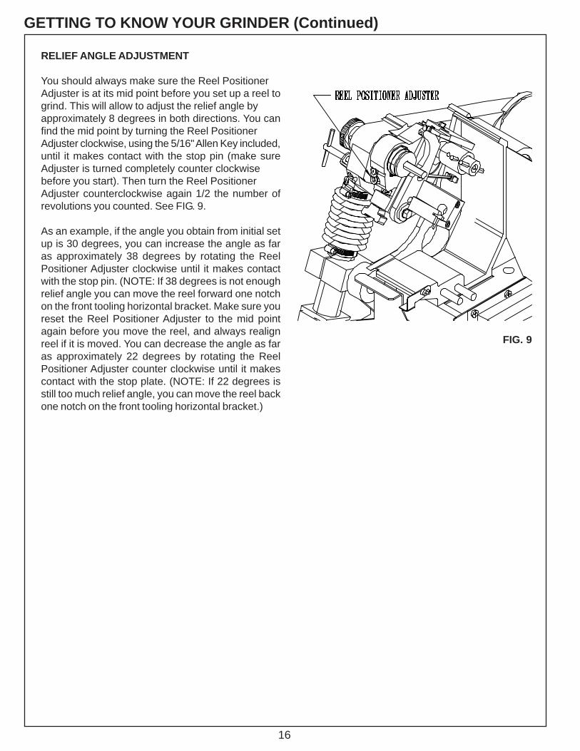
RELIEF ANGLE ADJUSTMENT
You should always make sure the Reel PositionerAdjuster is at its mid point before you set up a reel togrind. This will allow to adjust the relief angle byapproximately 8 degrees in both directions. You canfind the mid point by turning the Reel PositionerAdjuster clockwise, using the 5/16" Allen Key included,until it makes contact with the stop pin (make sureAdjuster is turned completely counter clockwisebefore you start). Then turn the Reel PositionerAdjuster counterclockwise again 1/2 the number ofrevolutions you counted. See FIG. 9.
As an example, if the angle you obtain from initial setup is 30 degrees, you can increase the angle as faras approximately 38 degrees by rotating the ReelPositioner Adjuster clockwise until it makes contactwith the stop pin. (NOTE: If 38 degrees is not enoughrelief angle you can move the reel forward one notchon the front tooling horizontal bracket. Make sure youreset the Reel Positioner Adjuster to the mid pointagain before you move the reel, and always realignreel if it is moved. You can decrease the angle as faras approximately 22 degrees by rotating the ReelPositioner Adjuster counter clockwise until it makescontact with the stop plate. (NOTE: If 22 degrees isstill too much relief angle, you can move the reel backone notch on the front tooling horizontal bracket.)
FIG. 9
17
OPERATING INSTRUCTIONSPREPARE MOWING UNIT FOR SHARPENING
When preparing a cutting unit for sharpening, followthe cutting unit manufacturers recommendations forproper maintenance. It is recommended that the reelto be sharpened is thoroughly cleaned. Remove wheelsand bed bar, if possible, from the reel. All bedknivesmust be ground when reels are sharpened. Inspect,adjust and/or replace any worn or damaged bearings.Make sure reel bearings are adjusted properly so thereel turns easily by hand.
Because this grinder mounts the reel using the rearroller, and front roller if applicable, the bearings mustbe in good repair with no freeplay. The front and rearrollers must be properly aligned parallel to the reelprior to grinding.
REELS WITH EXCESS TENSION ONTHE BEARINGS WILL BE EXTREMELYDIFFICULT TO SPIN GRIND AND COULDCAUSE DAMAGE TO THE REEL OR THESPIN DRIVE MECHANISM ON YOURGRINDER. NO MORE THAN 25. IN. LBSMAXIMUM TORQUE LOAD TO ROTATETHE REEL IS ALLOWED OR DAMAGE TOTHE SPIN DRIVE COULD OCCUR.
LIFTING REEL INTO POSITION
Boom ModelPosition the reel in front of the grinder on the floor sothe front of the mower faces towards the front of themachine. See FIG. 10 Hook the winch spreader baronto the reel. The clamps on the bar should be spacedevenly along the mower, so they do not slide as themower is being raised.
Rear Lift ModelLift or roll the reel onto the rear ramp so the front of themower faces towards the front of the machine. SeeFIG. 12. Raise the lift until even with table. Move reelonto grinder table and close the rear ramp.
THE OPERATOR SHOULD BEPOSITIONED AWAY FROM THEREEL. DO NOT STANDUNDERNEATH THE REEL AS IT ISBEING RAISED. GUIDE REEL ATARMS LENGTH.
FIG. 10
FIG. 11
FIG. 12

18
INSTALL REEL
Move the reel to the approximate position, having therear roller on the rear clamp support bracket, and frontroller on front roller clamps. See FIG. 11.
MAKE SURE GRINDING WHEEL IS LOWENOUGH TO CLEAR THE REEL. YOUCAN LOWER THE GRINDING WHEEL BYDEPRESSING THE INFEED JOG BUTTONDOWN.
Position front roller clamps as far out as possible to theends of the front roller, and center on the machine. SeeFIG. 11.
Set the vertical height of the clamps so the bottom ofthe reel is flush to 3/8" (10 mm) above the tablesurface. See FIG. 13.
Set the fore and aft position of the front clamps withthe reel Position Gage. Place the reel position gageagainst gaging surface. See FIG. 14. You want to alignthe center of the reel within the slot of the position gage.
THE HORIZONTAL SCALES AND VERTICALTOOLING SCALES MUST MATCH (LEFT ANDRIGHT) FOR PROPER ALIGNMENT.
For greensmower reels, the 3 1/2" (8 mm) diametergrinding wheel must clear the front roller V-bracket byapproximately 1/4" (6mm).
Make certain the reel is parallel to the front edge of thetable. Lock down with front clamps and rear clamp. SeeFIG. 15 & 16.
FIRMLY TIGHTEN ALL LOCKINGKNOBS BEFORE GRINDING.ANY LOOSENESS WILL AD-VERSELY AFFECT GRINDINGQUALITY.
OPERATING INSTRUCTIONS (Continued)
FIG. 13
FIG. 14
FIG. 16
FIG. 15
19
OPERATING INSTRUCTIONS (Continued)ALIGN THE REELNOTE: When measuring to the reel center shaft alwaysmake sure you are contacting an area free of dirt and grass.
HORIZONTAL ALIGNMENTInstall the horizontal extension bracket onto the carriage frontdowel pin and lock in place with knob. See FIG. 17.
Install the digital alignment gage onto the horizontalextension bracket pointing at the center of the reel shaft andlock into place with knob. See FIG. 18.
NOTE: The horizontal extension bracket is verticallyadjustable so the digital gage can be positioned to avoid reelframe members, etc. The mounting of the vertical slide tothe horizontal weldment has two additional mounting holesso the vertical slide can be tipped forward or back, again toavoid reel frame members, etc. See FIG. 17.
Loosen the two locking handles on the pivot assembly onthe right side of the traverse base, so that it can be adjustedin both the vertical and horizontal plane. See FIG. 19.
First, measure the left side of the reel as far to the left aspossible with the digital alignment gages, making sure the tipof the gage is centered on the reel center shaft. Set the gageto zero, then move the gage and measure the right side atthe same distance from reel centerline as the left side. Donot rotate the reel shaft except for a minimum amount toclear the gage when taking measurements. Adjust theorange horizontal handwheel. See FIG. 19. First note theamount the reel is out of alignment. Then, with the digitalgage still on the right side of the reel, turn the orangehorizontal handwheel in the direction required until the gagereads zero. Now continue turning the handwheel until thegage reads the then full amount of the offset again. Repeatthe process until alignment is within .002" (.05 mm). Lockthe orange horizontal locking handle when done.
Example: If the reel center shaft is off .085 left to right, turnthe handwheel from .085 to zero and then continue to turnuntil it reads .085 additional on the other sideof zero.
The reason for this is that the traverse framepivots on the left end and is adjusted onthe right end. Anytime the adjusting endis moved to change the right sidedimension, the left side dimension is alsochanged at a ratio to the right side. By overcompensating at the adjusting end you will compensatefor this movement and get the reel aligned much faster.
Aligning the reel to a value less than .002 (.05 mm) will notimprove the quality of the reel grind and will extend thealignment time. DO NOT ALIGN THE REEL ANYCLOSER THAN .002 (.05 mm).
Remove the gage. Remove the horizontal extension bracketand store it on the mount located on the outside of the rightside grinder leg.
FIG. 18
FIG. 17
FIG. 19
FORWARD & BACKWARDMOUNTING HOLES
HORIZONTAL EXTENSIONBRACKET FRONT
DOWEL PIN
LOCK KNOB
GREY VERTICALLOCKING HANDLE
ORANGE HORIZONTALHANDWHEEL
GREY VERTICALHANDWHEEL
ORANGE HORIZONTALLOCKING HANDLE
TRAVERSE BASE STANDING ALONEWITHOUT DUST PROTECTIONCOMPONENTS
20
OPERATING INSTRUCTIONS (Continued)
VERTICAL ALIGNMENT
Install the digital alignment gage vertically on thecarriage front dowel pin and pointing at the center ofthe reel shaft. Lock into place with knob. See FIG. 20
First, measure the left side of the reel as far to theleft as possible, set the gage to zero, then measurethe right side, at the same distance from reelcenterline as the left side. See FIG. 21. Do not rotatethe reel shaft except for a minimum amount to clearthe gage when taking measurements. Adjust thegrey vertical handwheel. See FIG. 19. First note theamount the reel is out of alignment. Then, with thedigital gage still on the right side of the reel, turn theorange horizontal handwheel in the direction requireduntil the gage reads zero. Now continue turning thehandwheel until the gage reads the then full amount ofthe offset again. Repeat until alignment is within .002"(.05 mm).
Example: If the reel center shaft is off .085 left to right,turn the handwheel from .085 to zero and thencontinue to turn until it reads .085 additional on the otherside of zero.
The reason for this is that the traverse frame pivots onthe left end and is adjusted on the right end. Anytimethe adjusting end is moved to change the right sidedimension, the left side dimension is also changed ata ratio to the right side. By over compensating at theadjusting end you will compensate for this movementand get the reel aligned much faster.
Aligning the reel to a value less than .002 (.05 mm) willnot improve the quality of the reel grind and will extendthe alignment time. DO NOT ALIGN THE REEL ANYCLOSER THAN .002 (.05 mm).
Lock the grey vertical locking handle when done.Remove and store the gage on the mount located onthe outside of the right side of the grinder.
FIG. 21
FIG. 20
LOCK KNOB
ALIGNMENT GAGE
21
OPERATING INSTRUCTIONS (Continued)ATTACHING THE VARIABLE SPEED SPIN DRIVEUNIT TO THE REEL
The spin drive unit attaches to the end of the reel shaftor a drive system component. Consult the cutting unitmanufacturer for proper spin drive placement andattachment. Determine which side to mount the spindrive. This will generally be the same drive systemcomponent used for backlapping. See FIG. 22.
Attach the spin drive unit onto the appropriate side.
When spin grinding, the reel should turn in the samedirection as the grinding wheel. See FIG. 23.
Before positioning the spin unit you should familiarizeyourselves with the available adjustments and coupler/drive assemblies. See FIG. 24.
KNOB A--Adjust the scissor bar to move the unit up and down.
KNOB B--(2 each)Allows the spin unit to be loosened and moved in andout.
KNOB C & D--Allow the spin assembly to be loosened from thesupport bar frame and moved side to side.
When positioning the spin unit it will be necessary tocomplete several of the above adjustments to properlyalign the spin unit to the reel.
FIG. 22
FIG.23
FIG. 24
22
The following procedures will make setting up the spin drive uniteasier.
1.
2.
3.
4.
5.
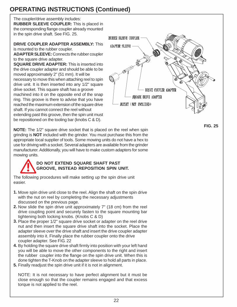
OPERATING INSTRUCTIONS (Continued)The coupler/drive assembly includes:RUBBER SLEEVE COUPLER: This is placed inthe corresponding flange coupler already mountedin the spin drive shaft. See FIG. 25.
DRIVE COUPLER ADAPTER ASSEMBLY: Thisis mounted to the rubber coupler.ADAPTER SLEEVE: Connects the rubber couplerto the square drive adapter.SQUARE DRIVE ADAPTER: This is inserted intothe drive coupler adapter and should be able to bemoved approximately 2" (51 mm). It will benecessary to move this when attaching reel to spindrive unit. It is then inserted into any 1/2" squaredrive socket. This square shaft has a groovemachined into it on the opposite end of the snapring. This groove is there to advise that you havereached the maximum extension of the square driveshaft. If you cannot connect the reel withoutextending past this groove, then the spin unit mustbe repositioned on the tooling bar (knobs C & D).
NOTE: The 1/2" square drive socket that is placed on the reel when spingrinding is NOT included with the grinder. You must purchase this from theappropriate local supplier of tools. Some mowing units do not have a hex touse for driving with a socket. Several adapters are available from the grindermanufacturer. Additionally, you will have to make custom adapters for somemowing units.
FIG. 25
DO NOT EXTEND SQUARE SHAFT PASTGROOVE, INSTEAD REPOSITION SPIN UNIT.
Move spin drive unit close to the reel. Align the shaft on the spin drivewith the nut on reel by completing the necessary adjustmentsdiscussed on the previous page.Now slide the spin drive unit approximately 7" (18 cm) from the reeldrive coupling point and securely fasten to the square mounting bartightening both locking knobs. (Knobs C & D)Place the proper 1/2" square drive socket or adapter on the reel drivenut and then insert the square drive shaft into the socket. Place theadapter sleeve over the drive shaft and insert the drive coupler adapterassembly into it. Finally place the rubber coupler onto the drivecoupler adapter. See FIG. 22By holding the square drive shaft firmly into position with your left handyou will be able to move the other components to the right and insertthe rubber coupler into the flange on the spin drive unit. When this isdone tighten the T-Knob on the adapter sleeve to hold all parts in place.Finally readjust the spin drive unit if it is not in alignment.
NOTE: It is not necessary to have perfect alignment but it must beclose enough so that the coupler remains engaged and that excesstorque is not applied to the reel.
23
OPERATING INSTRUCTIONS (Continued)SETUP PROCEDURE FOR SPIN DRIVERPM VERSUS TRANSVERSE SPEED
SPIN DRIVE RPM
SPIN DRIVE RPM IS VERY IMPORTANT IN ACHIEVINGA QUALITY GRIND. USE CARE IN ESTABLISHING THESPIN DRIVE RPM, PER THE INSTRUCTIONS BELOW.
Generally, the Spin Drive RPM will be between 180 RPM(45%) and 380 RPM (100%). The speed required to spin aspecific reel is dependant on reel diameter, the number ofreel blades, and reel hardness. For all reels, there is anoptimum Spin Speed where there is an AGGRESSIVE, yetsmooth grind as you spin grind the reel. Your objective is tospin grind the reel as aggressively and as fast as possiblewhile maintaining top quality.
It is recommended to start grinding each reel at a SpinSpeed of 200 RPM (50%) and evaluate the RPM byadjusting higher and lower to optimize the Spin Speed forthat reel. If the Spin Speed is incorrectly set, you canexperience two problems, grinding wheel dressing orgrinding wheel resonance. Each of these problems isexplained below.
On some reels, especially small diameter high blade countreels if the Spin Speed RPM is set to high, the reel can actas a dresser to the grinding wheel. There can develop whatappears to be a very aggressive grind (as if the infeed hasself infed) and then a sudden stop of grinding with nogrinding wheel to reel contact. If this occurs, your Spin Speedwas set to high and you effectively dressed your grindingwheel.
Some reels have a resonant RPM where the reel goes intoharmonics with the grinding wheel and the resonancevibrates the grinder and results in a very bad grind. Bychanging the Spin Speed to a higher or lower RPM you willmove out of the resonant range.
After determining the best Spin Speed RPM for a reel, notethe RPM on the "Set-up Chart" in the "NOTES" section.See page 33. By noting the correct RPM, you will avoidevaluating the Spin Speed the next time you grind the reel.
TRAVERSE DRIVE RPMThe Traverse Speed potentiometer is adjustable fromapproximately 5 feet per minute [1.5 meters per minute] to35 feet per minute [10 meters per minute]. It isrecommended to grind between 15 and 20 feet per minute[4 and 6 meters per minute].
24
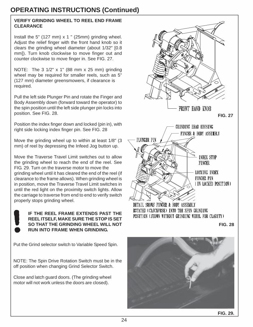
OPERATING INSTRUCTIONS (Continued)VERIFY GRINDING WHEEL TO REEL END FRAMECLEARANCE
Install the 5" (127 mm) x 1 " (25mm) grinding wheel.Adjust the relief finger with the front hand knob so itclears the grinding wheel diameter (about 1/32" [0.8mm]). Turn knob clockwise to move finger out andcounter clockwise to move finger in. See FIG. 27.
NOTE: The 3 1/2" x 1" (88 mm x 25 mm) grindingwheel may be required for smaller reels, such as 5"(127 mm) diameter greensmowers, if clearance isrequired.
Pull the left side Plunger Pin and rotate the Finger andBody Assembly down (forward toward the operator) tothe spin position until the left side plunger pin locks intoposition. See FIG. 28.
Position the index finger down and locked (pin in), withright side locking index finger pin. See FIG. 28
Move the grinding wheel up to within at least 1/8" (3mm) of reel by depressing the Infeed Jog button up.
Move the Traverse Travel Limit switches out to allowthe grinding wheel to reach the end of the reel. SeeFIG. 29. Turn on the traverse motor to move thegrinding wheel until it has cleared the end of the reel (ifclearance to the frame allows). When grinding wheel isin position, move the Traverse Travel Limit switches inuntil the red light on the proximity switch lights. Allowthe carriage to traverse from end to end to verify switchproperly stops grinding wheel.
Put the Grind selector switch to Variable Speed Spin.
NOTE: The Spin Drive Rotation Switch must be in theoff position when changing Grind Selector Switch.
Close and latch guard doors. (The grinding wheelmotor will not work unless the doors are closed).
IF THE REEL FRAME EXTENDS PAST THEREEL ITSELF, MAKE SURE THE STOP IS SETSO THAT THE GRINDING WHEEL WILL NOTRUN INTO FRAME WHEN GRINDING.
FIG. 29.
FIG. 27
FIG. 28
25
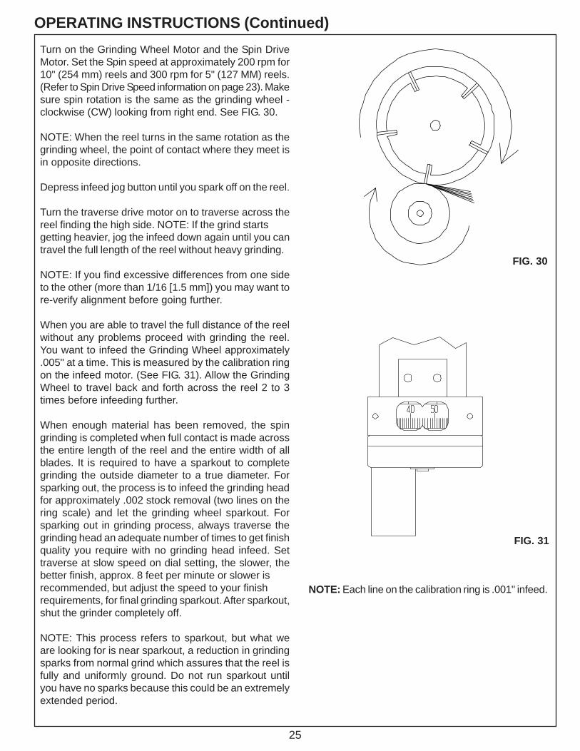
OPERATING INSTRUCTIONS (Continued)Turn on the Grinding Wheel Motor and the Spin DriveMotor. Set the Spin speed at approximately 200 rpm for10" (254 mm) reels and 300 rpm for 5" (127 MM) reels.(Refer to Spin Drive Speed information on page 23). Makesure spin rotation is the same as the grinding wheel -clockwise (CW) looking from right end. See FIG. 30.
NOTE: When the reel turns in the same rotation as thegrinding wheel, the point of contact where they meet isin opposite directions.
Depress infeed jog button until you spark off on the reel.
Turn the traverse drive motor on to traverse across thereel finding the high side. NOTE: If the grind startsgetting heavier, jog the infeed down again until you cantravel the full length of the reel without heavy grinding.
NOTE: If you find excessive differences from one sideto the other (more than 1/16 [1.5 mm]) you may want tore-verify alignment before going further.
When you are able to travel the full distance of the reelwithout any problems proceed with grinding the reel.You want to infeed the Grinding Wheel approximately.005" at a time. This is measured by the calibration ringon the infeed motor. (See FIG. 31). Allow the GrindingWheel to travel back and forth across the reel 2 to 3times before infeeding further.
When enough material has been removed, the spingrinding is completed when full contact is made acrossthe entire length of the reel and the entire width of allblades. It is required to have a sparkout to completegrinding the outside diameter to a true diameter. Forsparking out, the process is to infeed the grinding headfor approximately .002 stock removal (two lines on thering scale) and let the grinding wheel sparkout. Forsparking out in grinding process, always traverse thegrinding head an adequate number of times to get finishquality you require with no grinding head infeed. Settraverse at slow speed on dial setting, the slower, thebetter finish, approx. 8 feet per minute or slower isrecommended, but adjust the speed to your finishrequirements, for final grinding sparkout. After sparkout,shut the grinder completely off.
NOTE: This process refers to sparkout, but what weare looking for is near sparkout, a reduction in grindingsparks from normal grind which assures that the reel isfully and uniformly ground. Do not run sparkout untilyou have no sparks because this could be an extremelyextended period.
FIG. 30
FIG. 31
NOTE: Each line on the calibration ring is .001" infeed.
26
OPERATING INSTRUCTIONS (Continued)RELIEF GRIND
Replace the grinding wheel with the appropriate wheelfor relief grinding. Generally a 5" (127 mm) Dia. x 3/8"(10 mm) wide, will be used. As the reel diameter getssmaller and the number of blades increases the reliefgrinding wheel diameter must get smaller. That is whya 5" Dia. (127 mm) x 3/8" (10mm) wide and a 3 1/2"Dia. (88 mm) x 3/8" (10mm) wide wheel are furnishedwith the grinder. As a general rule, use the largestgrinding wheel practical to relief grind. NOTE: 5" (127MM) diameter greensmower reels with 11 bladesrequire a 3.5" (89 mm) diameter or smaller grindingwheel. Adjust the relief guide finger with the front handknob so it slightly misses the smaller grinding wheeldiameter (about 1/32" [1 mm]).
REEL SPIRAL
Check to see if your mowing unit is normal or reversehelix.NOTE: As you look into the guide finger on PAGE 29,
IT SHOWS THE NORMAL REEL HELIX. Thehigh point of the relief finger is on the right handside of the grinding wheel.
As you look into the guide finger on PAGE 30,IT SHOWS THE REVERSE REEL HELIX. Thehigh point of the relief finger is on the right handside of the grinding wheel.
Most mowing units are normal helix.
THE HIGH POINT OF THE RELIEF FINGERMUST ALWAYS BE AT THE CORNER OFTHE GRINDING WHEEL THAT IS MAKINGCONTACT WITH THE REEL. ON THISGRINDER THAT IS ALWAYS THE RIGHTHAND SIDE OF THE GRINDING WHEEL.SEE PAGES 29 AND 30.
27
OPERATING INSTRUCTIONS (Continued)
NO
RM
AL
HEL
IX
For a
NO
RM
AL
HE
LIX
reel
, the
grin
ding
whe
elsh
ould
wea
r to
mat
ch th
e an
gle
of th
e re
el b
lade
.
NO
TE: T
he s
quar
e fa
ced
grin
ding
whe
el a
s fro
mth
e fa
ctor
y ca
n be
use
d fo
r nor
mal
hel
ix re
els
and
will
wea
r to
mat
ch th
e re
el b
lade
hel
ix.
Pre
fere
d D
ress
ing
New
Stra
ight
Whe
el
Rig
ht S
ide
of W
heel
Mus
t Con
tact
Firs
t
Mat
chin
g An
gle
Act
ual G
rindi
ng W
heel
Con
tact
Poi
nt
28
OPERATING INSTRUCTIONS (Continued)
For a
REV
ERSE
HEL
IX re
el, t
he g
rindi
ng w
heel
shou
ld b
e dr
esse
d to
mat
ch th
e an
gle
of th
e re
elbl
ade.
It i
s re
com
men
ded
that
a s
light
ly la
rger
angl
e is
dre
ssed
on
the
whe
el s
o th
e rig
ht s
ide
of th
e w
heel
is c
onta
ctin
g th
e bl
ade
prio
r to
the
left
side
as
show
n. T
he g
rindi
ng w
heel
will
then
wea
r to
a m
atch
.
If yo
u do
not
dre
ss th
e gr
indi
ng w
heel
so
the
right
side
con
tact
s fir
st y
ou m
ay n
ot re
lief g
rind
part
ofth
e la
st 3
/8" [
10 m
m] o
f the
bla
de.
REV
ERSE
HEL
IX
NO
TE: A
whe
el th
at h
as b
een
wor
n to
mat
ch a
nor
mal
helix
can
gen
eral
ly b
e re
mov
ed a
nd re
vers
ed to
grin
der
reve
rse
helix
reel
s.
29
OPERATING INSTRUCTIONS (Continued)
Reset the Traverse Limit Proximity Switch so the grindingwheel clears the reel at both ends by approximately 1/16"(1.5 mm).
Pull the left side plunger pin and rotate the Finger andBody Assembly up (back, away from the operator) intothe relief position until the left side plunger pin locks intoposition. See FIG. 32.
Pull the right side locking index finger pin to release theindex finger and rotate the handle into the retractedposition. See FIG. 32.
Set Grind Selector to variable torque relief. (NOTE: TheSpin Drive Rotation switch must be in the OFF positionwhen changing Grind Selector switch.) Set Spin DriveRotation switch to rotate the reel into the stop finger,counterclockwise (CCW) when looking at the right side.NOTE: Relief torque reel rotation is always opposite spinrotation.
With the traverse in home position, jog the grinding headup while manually rotating the reel until the index fingertouches the blade.
NOTE: The Index Finger position must be set to stop thereel blade and allow traversing to the left without the bladehitting the side of the relief finger. This position must alsoallow approximately 1/32" (1 mm) free play of the indexfinger when the blade is resting on the high point of therelief finger. See FIG. 32.
Turn the traverse speed pot to zero, then turn the traversedrive motor on. Using the speed pot to slowly move andstop the grinding wheel, jog left until the reel blade is onthe relief finger. Adjust the index finger positioning byloosening the Index Lock Handle and rotating the indexadjust lever on the right side of the grinding head*. SeeFIG. 32. When this is completed, lock it into position bytightening the index lock handle. Continue to jog thegrinding head up until there is minimal clearance betweenthe reel blade and the grinding wheel.
FIG. 32
30
OPERATING INSTRUCTIONS (Continued)
Turn the Spin Drive motor on.
NOTE: The spin drive will apply torque load againstthe fingers.
Set the Relief Torque Potentiometer at approximately15. NOTE: Free turning reels may need a lower valuethan 15. Stiff reels or reels with a drive train may needa higher torque than 15. Do not exceed 45 on therelief torque potentiometer setting.
Jog the traverse all the way to the left watching forproper clearance between the grinding wheel and theblade. Check for proper clearance between the indexfinger (after releasing from blade at far left position)and the front side of the blade on the return trip to thehome position. Also verify clearance to the reel bladesupport spiders.
Stop the traverse in home position and check for aproper blade index. The traverse drive control isfactory set with a two second dwell time before itreverses the carriage travel. This is to allow time forthe reel to rotate and the index finger to catch the nextblade. If necessary the dwell time can be adjusted(refer to Control Board Potentiometer Adjustmentssection on Pages 22-24 in the Assembly and ServiceManual).
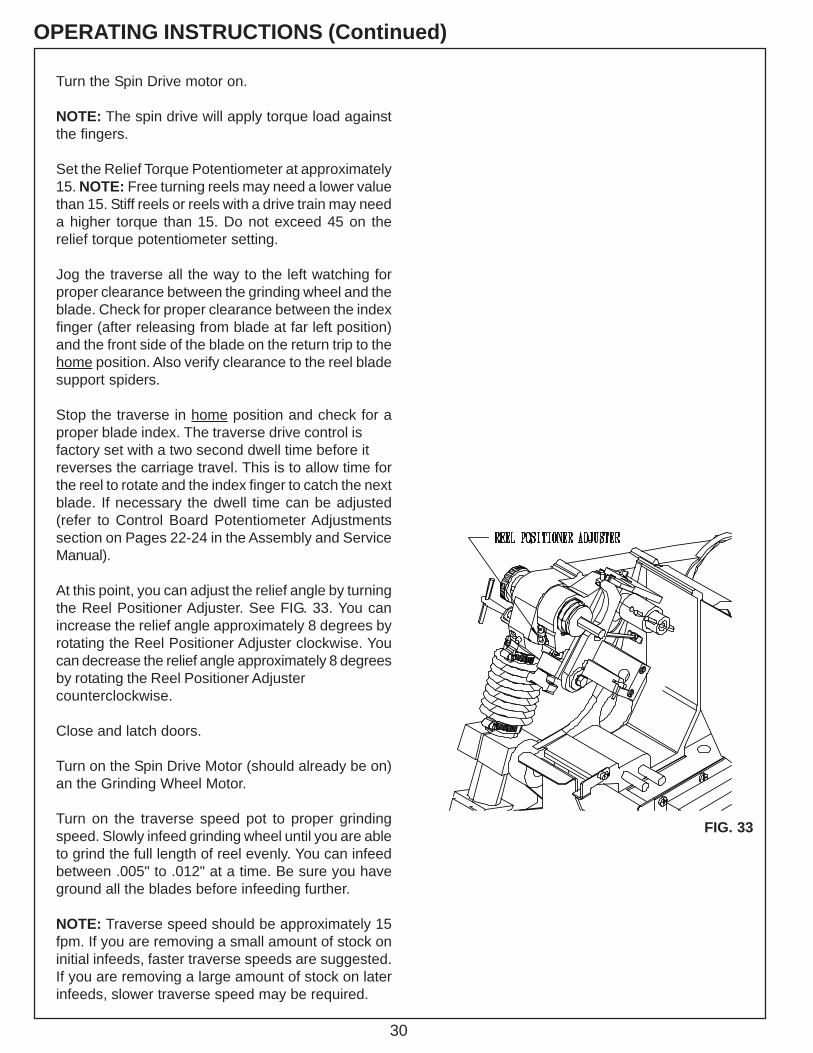
At this point, you can adjust the relief angle by turningthe Reel Positioner Adjuster. See FIG. 33. You canincrease the relief angle approximately 8 degrees byrotating the Reel Positioner Adjuster clockwise. Youcan decrease the relief angle approximately 8 degreesby rotating the Reel Positioner Adjustercounterclockwise.
Close and latch doors.
Turn on the Spin Drive Motor (should already be on)an the Grinding Wheel Motor.
Turn on the traverse speed pot to proper grindingspeed. Slowly infeed grinding wheel until you are ableto grind the full length of reel evenly. You can infeedbetween .005" to .012" at a time. Be sure you haveground all the blades before infeeding further.
NOTE: Traverse speed should be approximately 15fpm. If you are removing a small amount of stock oninitial infeeds, faster traverse speeds are suggested.If you are removing a large amount of stock on laterinfeeds, slower traverse speed may be required.
FIG. 33

31
--This page intentionally left blank for note taking purposes.--

32
REEL SETUP CHART N
ote:
Thes
e di
men
sion
s w
ill va
ry d
ue to
reel
pos
ition
infra
me,
reel
dia
., he
ight
of c
ut, r
olle
r pos
ition
, etc
.U
se th
ese
valu
es a
s a
guid
e on
ly.R
EEL
MA
KE,
MO
DEL
&H
EIG
HT
OF
CU
T
PRO
GR
AM
NA
ME
TOO
LIN
GVE
RTIC
ALSC
ALE
TOO
LIN
GD
ISTA
NC
EAP
ART
SPIN
DR
IVE
MO
UN
TIN
GSI
DE
R o
r L
GR
IND
ING
WH
EEL
DIA.
REE
L SE
TUP
CH
AR
TTO
OLI
NG
HORI
ZONT
ALSC
ALE
SPIN
TOR
QU
ESE
TTIN
G
TRAV
ERSE
SPEE
DSE
TTIN
G
NO
TES
SPIN
SPEE
DSE
TTIN
G