Embed Size (px)
Citation preview
adex-HC
Please refer to adex.ca for the latest version of this document, specifications (PDF + Word), technical drawings, product technical sheets, warranties, maintenance guide....and much more.
DescriptionThe adex-HC system is a “hard-coat” system wich incorporates the use of a rigid fibre-reinforced basecoat and an extruded polystyrene insulation (xPS). The result is a system that provides increased thermal and impact resistance.
Benefits• Provides a monolithic blanket of insulation; reduces energy use• Seals the building envelope and ensures seamless protection of the
substrate• Allows for the drainage of incidental moisture• Durable and flexible• Architectural design flexibility• Resists dirt, fading and abrasion
Features• Seamless substrate protection• Non-combustible basecoat• Unlimited colour selection
1 EIFS TAPE & PRIMER
2 hyDRoFLEx STD MEMBRANE
3 ADEx BASECoAT
4 ExTRUDED PoLySTyRENE
5 hC MESh
6 NIVELEx BASECoAT
7 PRIMEx PRIMER
8 FINISh CoAT
10/2012
System Specification adex-HC
This document contains information made available to specialised designers, architects, engineers or other professionals, as a guide only, to help them prepare a technical specification. Specialised designers, architects, engineers or other professionals bear the complete responsibility of evaluating usability, conformity and relevance of the information in view of the particular project and they commit to verify all technical data in the present document in order to assess their suitability in the project. When such use is done by specialised designers, architects, engineers or other professionals, they take full responsibility for the information as if it were their own. Use by a non-specialised person is strongly advised against.
PART 4 GENERAL
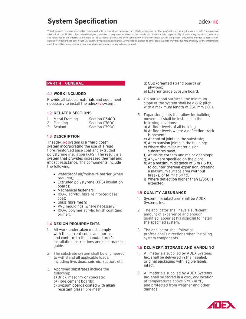
4.1 WoRk INCLudEd
Provide all labour, materials and equipment necessary to install the adex-HC system.
1.2 RELATEd SECTIoNS
1. Metal Framing Section 054002. Flashing Section 076003. Sealant Section 07900
1.3 dESCRIPTIoN
Theadex-HC system is a “hard-coat” system incorporating the use of a rigid fibre-reinforced base coat and extruded polystyrene insulation (XPS). The result is a system that provides increased thermal and impact resistance. The components include the following:
Waterproof air/moisture barrier (when required);
Extruded polystyrene (XPS) insulation boards;
Mechanical fasteners; 100% acrylic, fibre-reinforced base
coat; Glass fibre mesh; PVC mouldings (where necessary); 100% polymer acrylic finish coat (and
primer).
1.4 dESIGN REquIREmENTS
1. All work undertaken must comply with the current codes and norms, and conform to the manufacturer’s installation instructions and best practice guide.
2. The substrate system shall be engineered to withstand all applicable loads, including live, dead, seismic, suction, etc.
3. Approved substrates include the following:
a) Brick, masonry or concrete; b) Fibre cement boards; c) Gypsum boards coated with alkali-
resistant glass fibre mesh;
d) OSB (oriented strand board) or plywood;
e) Exterior grade gypsum board.
4. On horizontal surfaces, the minimum slope of the system shall be a 6:12 pitch with a maximum length of 250 mm (10”).
5. Expansion joints that allow for building movement shall be installed in the following locations:
a) At floor levels of all buildings; b) At floor levels where a deflection track
is present; c) At control joints in the substrate; d) At expansion joints in the building; e) Where dissimilar materials or
substrates meet; f) At inside corners and major openings; g) Anywhere specified on the plans; h) At a maximum distance of 5 m (16 ft),
to counter thermal expansion, creating a maximum surface area (without breaks) of 14 m2 (150 ft2);
i) Where deflection higher than L/360 is expected.
1.5 quALITy ASSuRANCE
1. System manufacturer shall be ADEX Systems Inc.
2. The applicator shall have a sufficient amount of experience and enough qualified labour at his disposal to install the specified system.
3. The applicator shall follow all professional’s directions when installing system components.
1.6 dELIvERy, SToRAGE ANd HANdLING
1. All materials supplied by ADEX Systems Inc. shall be delivered in their sealed, original packaging with legible labels intact.
2. All materials supplied by ADEX Systems Inc. shall be stored in a cool, dry location at temperatures above 5 ºC (41 ºF) and protected from weather and other damage.
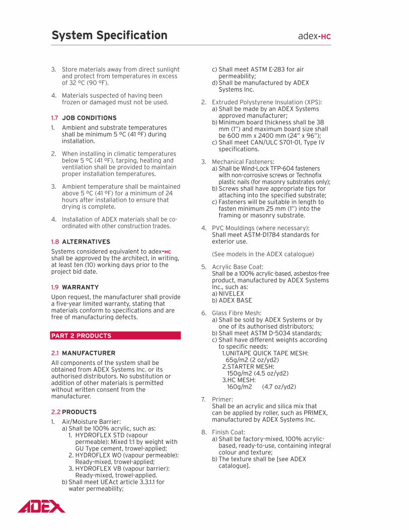
3. Store materials away from direct sunlight and protect from temperatures in excess of 32 ºC (90 ºF).
4. Materials suspected of having been frozen or damaged must not be used.
1.7 Job CoNdITIoNS
1. Ambient and substrate temperatures shall be minimum 5 ºC (41 ºF) during installation.
2. When installing in climatic temperatures below 5 ºC (41 ºF), tarping, heating and ventilation shall be provided to maintain proper installation temperatures.
3. Ambient temperature shall be maintained above 5 ºC (41 ºF) for a minimum of 24 hours after installation to ensure that drying is complete.
4. Installation of ADEX materials shall be co-ordinated with other construction trades.
1.8 ALTERNATIvES
Systems considered equivalent to adex-HC
shall be approved by the architect, in writing, at least ten (10) working days prior to the project bid date.
1.9 WARRANTy
Upon request, the manufacturer shall provide a five-year limited warranty, stating that materials conform to specifications and are free of manufacturing defects.
PART 2 PRoduCTS
2.1 mANufACTuRER
All components of the system shall be obtained from ADEX Systems Inc. or its authorised distributors. No substitution or addition of other materials is permitted without written consent from the manufacturer.
2.2 PRoduCTS
1. Air/Moisture Barrier: a) Shall be 100% acrylic, such as: 1. HYDROFLEX STD (vapour
permeable): Mixed 1:1 by weight with GU Type cement, trowel-applied;
2. HYDROFLEX WO (vapour permeable): Ready-mixed, trowel-applied;
3. HYDROFLEX VB (vapour barrier): Ready-mixed, trowel-applied.
b) Shall meet UEAct article 3.3.1.1 for water permeability;
c) Shall meet ASTM E-283 for air permeability;
d) Shall be manufactured by ADEX Systems Inc.
2. Extruded Polystyrene Insulation (XPS): a) Shall be made by an ADEX Systems
approved manufacturer; b) Minimum board thickness shall be 38
mm (1”) and maximum board size shall be 600 mm x 2400 mm (24” x 96”);
c) Shall meet CAN/ULC S701-01, Type IV specifications.
3. Mechanical Fasteners: a) Shall be Wind-Lock TFP-604 fasteners
with non-corrosive screws or Technofix plastic nails (for masonry substrates only);
b) Screws shall have appropriate tips for attaching into the specified substrate;
c) Fasteners will be suitable in length to fasten minimum 25 mm (1”) into the framing or masonry substrate.
4. PVC Mouldings (where necessary): Shall meet ASTM-D1784 standards for
exterior use.
(See models in the ADEX catalogue)
5. Acrylic Base Coat: Shall be a 100% acrylic-based, asbestos-free
product, manufactured by ADEX Systems Inc., such as:
a) NIVELEX b) ADEX BASE
6. Glass Fibre Mesh: a) Shall be sold by ADEX Systems or by
one of its authorised distributors; b) Shall meet ASTM D-5034 standards; c) Shall have different weights according
to specific needs:1. UNITAPE QUICK TAPE MESH:
65g/m2 (2 oz/yd2)2. STARTER MESH:
150g/m2 (4.5 oz/yd2)3. HC MESH:
160g/m2 (4.7 oz/yd2)
7. Primer: Shall be an acrylic and silica mix that
can be applied by roller, such as PRIMEX, manufactured by ADEX Systems Inc.
8. Finish Coat: a) Shall be factory-mixed, 100% acrylic-
based, ready-to-use, containing integral colour and texture;
b) The texture shall be [see ADEX catalogue].
System Specification adex-HC
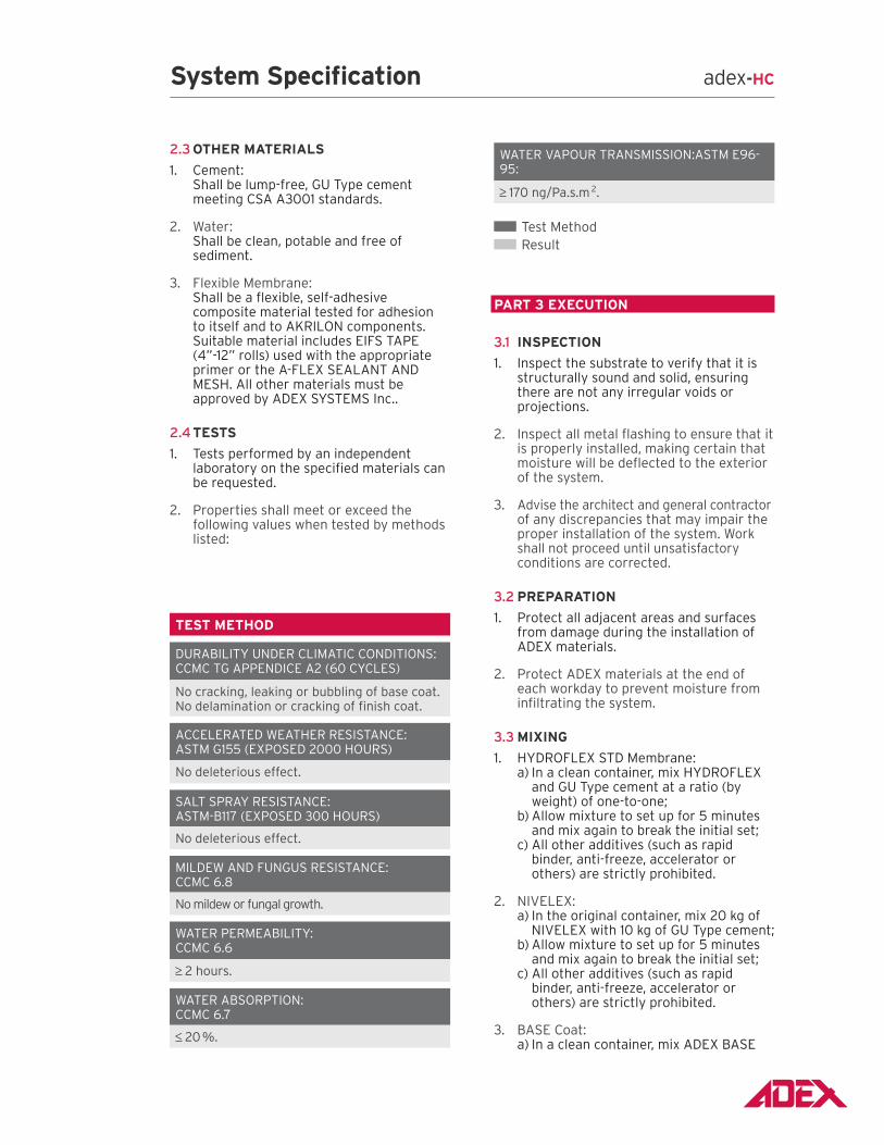
2.3 oTHER mATERIALS
1. Cement: Shall be lump-free, GU Type cement
meeting CSA A3001 standards.
2. Water: Shall be clean, potable and free of
sediment.
3. Flexible Membrane: Shall be a flexible, self-adhesive
composite material tested for adhesion to itself and to AKRILON components. Suitable material includes EIFS TAPE (4”-12” rolls) used with the appropriate primer or the A-FLEX SEALANT AND MESH. All other materials must be approved by ADEX SYSTEMS Inc..
2.4 TESTS
1. Tests performed by an independent laboratory on the specified materials can be requested.
2. Properties shall meet or exceed the following values when tested by methods listed:
TEST mETHod
DURABILITY UNDER CLIMATIC CONDITIONS: CCMC TG APPENDICE A2 (60 CYCLES)
No cracking, leaking or bubbling of base coat. No delamination or cracking of finish coat.
ACCELERATED WEATHER RESISTANCE: ASTM G155 (EXPOSED 2000 HOURS)
No deleterious effect.
SALT SPRAY RESISTANCE: ASTM-B117 (EXPOSED 300 HOURS)
No deleterious effect.
MILDEW AND FUNGUS RESISTANCE: CCMC 6.8
No mildew or fungal growth.
WATER PERMEABILITY: CCMC 6.6
2 hours.
WATER ABSORPTION: CCMC 6.7
20 %.
WATER VAPOUR TRANSMISSION:ASTM E96-95:
170 ng/Pa.s.m 2.
Test Method Result
PART 3 EXECuTIoN
3.1 INSPECTIoN
1. Inspect the substrate to verify that it is structurally sound and solid, ensuring there are not any irregular voids or projections.
2. Inspect all metal flashing to ensure that it is properly installed, making certain that moisture will be deflected to the exterior of the system.
3. Advise the architect and general contractor of any discrepancies that may impair the proper installation of the system. Work shall not proceed until unsatisfactory conditions are corrected.
3.2 PREPARATIoN
1. Protect all adjacent areas and surfaces from damage during the installation of ADEX materials.
2. Protect ADEX materials at the end of each workday to prevent moisture from infiltrating the system.
3.3 mIXING
1. HYDROFLEX STD Membrane: a) In a clean container, mix HYDROFLEX
and GU Type cement at a ratio (by weight) of one-to-one;
b) Allow mixture to set up for 5 minutes and mix again to break the initial set;
c) All other additives (such as rapid binder, anti-freeze, accelerator or others) are strictly prohibited.
2. NIVELEX: a) In the original container, mix 20 kg of
NIVELEX with 10 kg of GU Type cement; b) Allow mixture to set up for 5 minutes
and mix again to break the initial set; c) All other additives (such as rapid
binder, anti-freeze, accelerator or others) are strictly prohibited.
3. BASE Coat: a) In a clean container, mix ADEX BASE
System Specification adex-HC
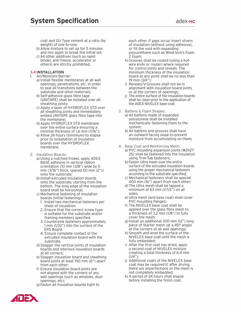
coat and GU Type cement at a ratio (by weight) of one-to-one;
b) Allow mixture to set up for 5 minutes and mix again to break the initial set;
c) All other additives (such as rapid binder, anti-freeze, accelerator or others) are strictly prohibited.
3.4 INSTALLATIoN 1. Air/Moisture Barrier: a) Install flexible membranes at all wall
openings, penetrations, etc. in order to seal all transitions between the substrate and other materials;
b) Self-adhesive glass fibre tape (UNITAPE) shall be installed over all sheathing joints;
c) Apply a layer of HYDROFLEX STD over all sheathing joints and immediately embed UNITAPE glass fibre tape into the membrane;
d) Apply HYDROFLEX STD membrane over the entire surface ensuring a minimal thickness of 1.6 mm (1/16”);
e) Allow 24 hours (minimum) to elapse prior to installation of insulation boards over the HYDROFLEX membrane.
2. Insulation Boards: a) Using a notched trowel, apply ADEX
BASE adhesive in vertical ribbon orientation (10 mm (3/8”) wide by 5 mm (3/16”) thick, spaced 50 mm (2”)) onto the substrate;
b) Install extruded insulation boards onto the substrate, starting from the bottom. The long edge of the insulation board shall be horizontal;
c) Mechanical fastening of insulation boards (initial fastening):
1. Install two mechanical fasteners per sheet of insulation.
2. Ensure that the correct screw type is suitable for the substrate and/or framing members specified.
3. Countersink fasteners approximately 1 mm (1/32”) into the surface of the EPS Board.
4. Ensure complete contact of the extruded insulation board with the substrate.
d) Stagger the vertical joints of insulation boards and interlock insulation boards at all corners;
e) Stagger insulation board and sheathing board joints at least 150 mm (6”) apart from each other;
f) Ensure insulation board joints are not aligned with the corners of any wall openings (such as windows, door openings, etc);
g) Fasten all insulation boards tight to
each other. If gaps occur, insert slivers of insulation (without using adhesive), or fill the void with expanding polyurethane such as Wind-lock’s Foam 2 Foam;
h) Grooves shall be routed (using a hot-wire knife or router) where required for control joints and reveals. The minimum thickness of the insulation board at any point shall be no less than 19 mm (3/4”);
i) Reveals/V-Grooves shall not be in alignment with insulation board joints or at the corners of openings;
j) The entire surface of the insulation boards shall be clean prior to the application of the ADEX NIVELEX base coat.
3. Battens & Foam Shapes: a) All battens made of expanded
polystyrene shall be installed mechanically fastening them to the system;
b) All battens and grooves shall have an outward-facing slope to prevent moisture from accumulating on them;
4. Base Coat and Reinforcing Mesh: a) PVC moulding expansion joints (#2027-
25) shall be fastened into the insulation using Trim-Tab fasteners;
b) Fasten Ultra mesh over the entire surface of the extruded insulation boards using the proper mechanical fasteners according to the substrate specified;
c) Mechanical fasteners shall be spaced 400 mm (16”) apart from each other;
d) The Ultra mesh shall be lapped a minimum of 63 mm (2-1/2”) on all sides;
e) Ultra mesh (and base coat) shall cover PVC moulding flanges;
f) The NIVELEX base coat shall be applied over the glass fibre mesh to a thickness of 3.2 mm (1/8”) to fully cover the mesh;
g) Install an additional 300 mm (12”) long piece of Starter mesh (at a 45º angle) at the corners of all wall openings;
h) Smooth and level the surface of the NIVELEX base coat until the mesh is fully embedded;
i) After the first coat has dried, apply a second coat of NIVELEX mixture creating a total thickness of 6.4 mm (1/4”);
j) Additional coats of the NIVELEX base coat may be required if, after drying, there are imperfections or the mesh is not completely embedded;
k) A period of 24 hours shall elapse before installing the finish coat.
System Specification adex-HC
5. Finish Coat: a) With a roller, apply an even coat of
ADEX PRIMEX primer (same colour as the finish coat) prior to installing the finish coat;
b) Trowel-apply a tight coat of ADEX Finish, texture [see ADEX catalogue] to a thickness not greater than the largest aggregate. Apply the finish coat in a continuous fashion, maintaining a wet edge. Levelling and texturing shall take place in one operation to give the ADEX Finish a uniform appearance;
c) Avoid applications in direct sunlight; d) Avoid applying finish coat at locations
where caulking will be installed; e) Ensure all PVC moulding connections
are properly sealed.
3.5 CLEAN-uP
1. Remove waste and left over materials (used in this section) from the job site.
2. Clean all adjacent materials and surfaces, and repair any defects caused to this application or any other work.
3.6 PRoTECTIoN
1. Ensure that the general contractor protects all work against moisture infiltration and other damages by installing the necessary flashing and caulking in a timely manner.
2. Provide protection against dirt, moisture, high humidity, and freezing temperatures until materials are fully dry.
System Specification adex-HC
Information in this document contains the current recommendations for the installation of the adex-HC system. It is only provided as a guide and is subject to modifications at any time without notice. ADEX Systems Inc. reserves the right to make any modification according to technological progress. Specialised designers, architects, engineers or other professionals that choose to make any use of this information bear the complete responsibility, whatever it be, direct or indirect, that could follow from such use. ADEX Systems Inc. does not bear any responsibility that could give way to damages, defaults, defects, deficiencies, prejudices, loss or decrease of profit, be they direct or indirect, resulting from such use of this information by specialised designers, architects, engineers or other professionals. Please refer to www.adex.ca for the latest version of this document.
CoRPoRATE SALES CENTER 7911, Marco Polo Montreal (Quebec) Canada H1E 1N8 www.adex.caP 514-648-1213 | f 514-648-9597
September 2012
Technical drawings adex-HC
Information in this document contains the current recommendations for the installation of the adex-HC system. It is only provided as a guide and is subject to modifications at any time without notice. ADEX Systems Inc. reserves the right to make any modification according to technological progress. Specialised designers, architects, engineers or other professionals that choose to make any use of this information bear the complete responsibility, whatever it be, direct or indirect, that could follow from such use. ADEX Systems Inc. does not bear any responsibility that could give way to damages, defaults, defects, deficiencies, prejudices, loss or decrease of profit, be they direct or indirect, resulting from such use of this information by specialised designers, architects, engineers or other professionals. Please refer to www.adex.ca for the latest version of this document.
adex-HC
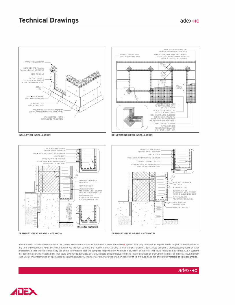
INSuLATIoN INSTALLATIoN REINfoRCING mESH INSTALLATIoN
TERmINATIoN AT GRAdE - mETHod A TERmINATIoN AT GRAdE - mETHod b
Technical drawings adex-HC
Information in this document contains the current recommendations for the installation of the adex-HC system. It is only provided as a guide and is subject to modifications at any time without notice. ADEX Systems Inc. reserves the right to make any modification according to technological progress. Specialised designers, architects, engineers or other professionals that choose to make any use of this information bear the complete responsibility, whatever it be, direct or indirect, that could follow from such use. ADEX Systems Inc. does not bear any responsibility that could give way to damages, defaults, defects, deficiencies, prejudices, loss or decrease of profit, be they direct or indirect, resulting from such use of this information by specialised designers, architects, engineers or other professionals. Please refer to www.adex.ca for the latest version of this document.
adex-HC
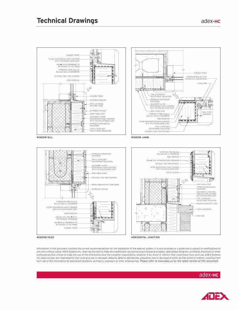
WINdoW SILL WINdoW JAmb
WINdoW HEAd HoRIzoNTAL JuNCTIoN
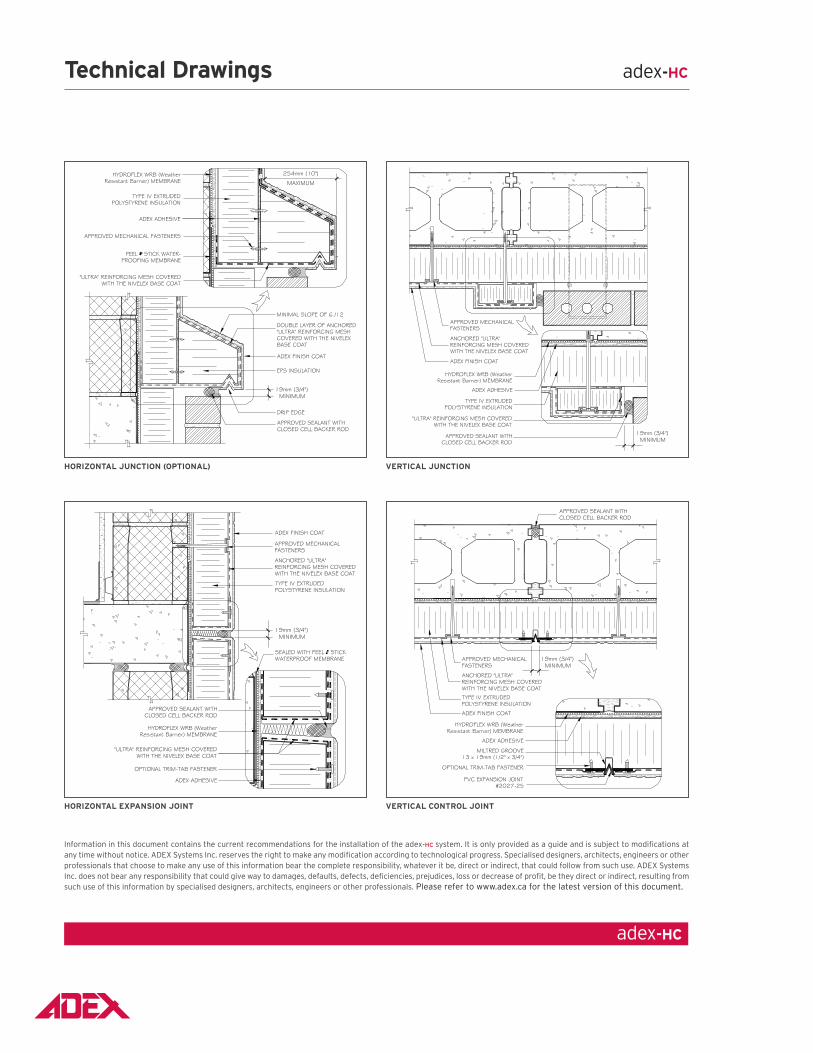
HoRIzoNTAL JuNCTIoN (oPTIoNAL) vERTICAL JuNCTIoN
HoRIzoNTAL EXPANSIoN JoINT vERTICAL CoNTRoL JoINT
Technical drawings adex-HC
adex-HC
Information in this document contains the current recommendations for the installation of the adex-HC system. It is only provided as a guide and is subject to modifications at any time without notice. ADEX Systems Inc. reserves the right to make any modification according to technological progress. Specialised designers, architects, engineers or other professionals that choose to make any use of this information bear the complete responsibility, whatever it be, direct or indirect, that could follow from such use. ADEX Systems Inc. does not bear any responsibility that could give way to damages, defaults, defects, deficiencies, prejudices, loss or decrease of profit, be they direct or indirect, resulting from such use of this information by specialised designers, architects, engineers or other professionals. Please refer to www.adex.ca for the latest version of this document.
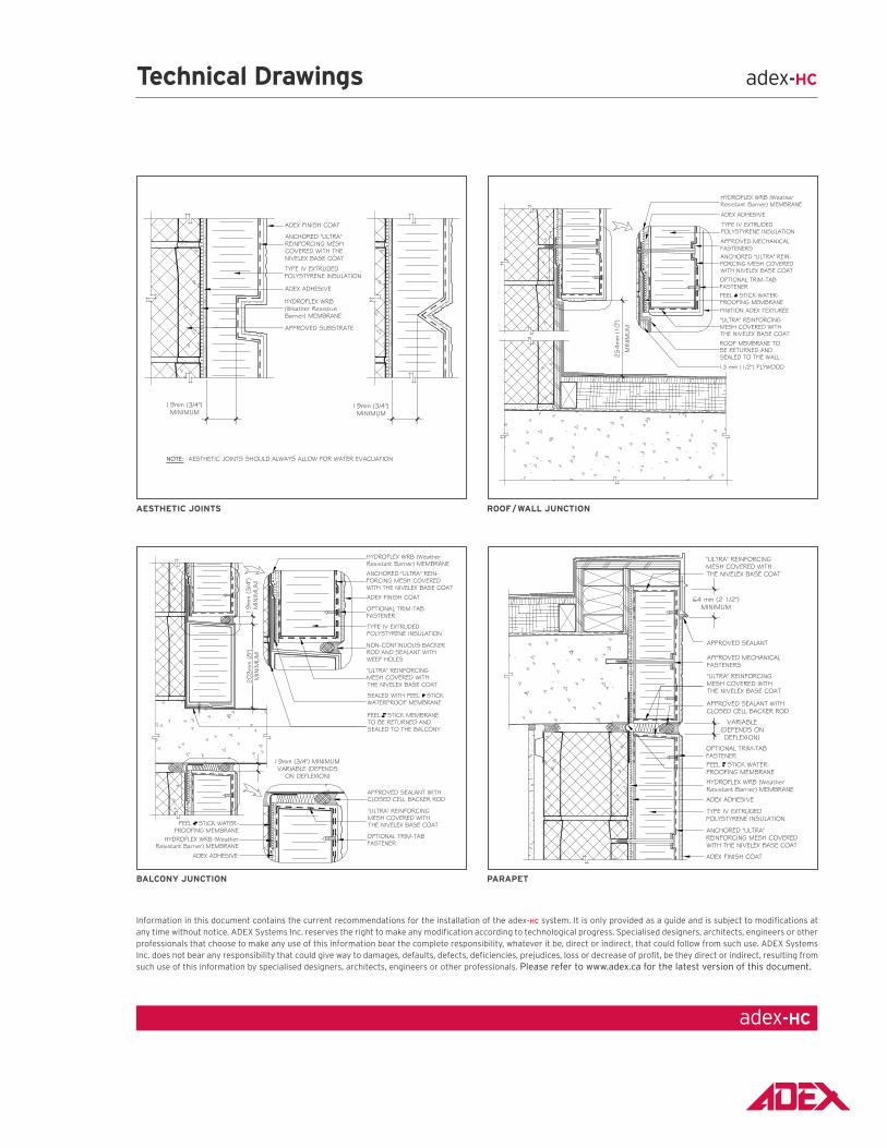
AESTHETIC JoINTS Roof / WALL JuNCTIoN
bALCoNy JuNCTIoN PARAPET
Technical drawings adex-HC
adex-HC
Information in this document contains the current recommendations for the installation of the adex-HC system. It is only provided as a guide and is subject to modifications at any time without notice. ADEX Systems Inc. reserves the right to make any modification according to technological progress. Specialised designers, architects, engineers or other professionals that choose to make any use of this information bear the complete responsibility, whatever it be, direct or indirect, that could follow from such use. ADEX Systems Inc. does not bear any responsibility that could give way to damages, defaults, defects, deficiencies, prejudices, loss or decrease of profit, be they direct or indirect, resulting from such use of this information by specialised designers, architects, engineers or other professionals. Please refer to www.adex.ca for the latest version of this document.
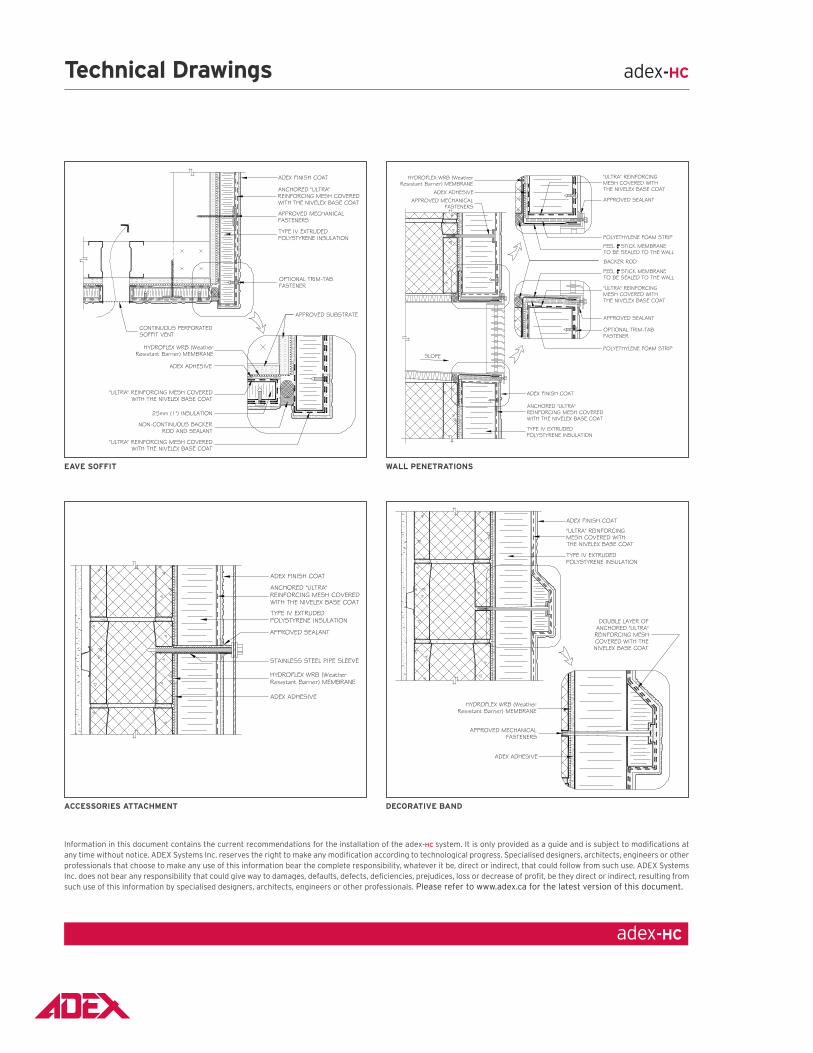
EAvE SoffIT WALL PENETRATIoNS
ACCESSoRIES ATTACHmENT dECoRATIvE bANd
Technical drawings adex-HC
adex-HC
Information in this document contains the current recommendations for the installation of the adex-HC system. It is only provided as a guide and is subject to modifications at any time without notice. ADEX Systems Inc. reserves the right to make any modification according to technological progress. Specialised designers, architects, engineers or other professionals that choose to make any use of this information bear the complete responsibility, whatever it be, direct or indirect, that could follow from such use. ADEX Systems Inc. does not bear any responsibility that could give way to damages, defaults, defects, deficiencies, prejudices, loss or decrease of profit, be they direct or indirect, resulting from such use of this information by specialised designers, architects, engineers or other professionals. Please refer to www.adex.ca for the latest version of this document.
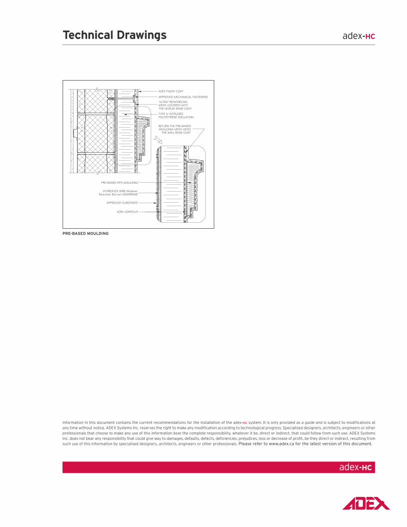
PRE-bASEd mouLdING
Technical drawings adex-HC
adex-HC
Information in this document contains the current recommendations for the installation of the adex-HC system. It is only provided as a guide and is subject to modifications at any time without notice. ADEX Systems Inc. reserves the right to make any modification according to technological progress. Specialised designers, architects, engineers or other professionals that choose to make any use of this information bear the complete responsibility, whatever it be, direct or indirect, that could follow from such use. ADEX Systems Inc. does not bear any responsibility that could give way to damages, defaults, defects, deficiencies, prejudices, loss or decrease of profit, be they direct or indirect, resulting from such use of this information by specialised designers, architects, engineers or other professionals. Please refer to www.adex.ca for the latest version of this document.