Embed Size (px)
Citation preview

Adel M. Sharaf
Behnam Khaki

Rising Cost /Depleting resources of fossil
fuels
Unreliable /Unproven Oil/NG Reserves
Climate change/Global warming and CO2
emissions
Feeder Congestion and additional Costs of Energy Transmission and need to reduce transmission Losses

Utilization and Interfacing of Green Energy of Renewable Sources
What is the challenge?
Robust Interface-Decoupling and need to Enhance Power Quality, Energy Utilization and Dynamic
Voltage Stability

New Flexible AC Transmission System (FACTS) Device-Including Hybrid Modulated Filter-C Type-Capacitor Compensator (MFCCC)
What Does it Include?
1. Capacitor Banks
2. C Type Filter
3. IGBT/MOSFET Power Electronic Switches

1. Designing Modulated Filter –compensation
Schemes
2. Devising A Controller Handling On-Off
Sequences in IGBT/MOSFET Switches
3. Testing The Effects of MFCCC in a Grid (by use
of MATLAB- Simulink Software Environment)

One series and Two shunt 3-phas switched capacitor banks connected in DELTA shape
C Type Filters following the Delta-Capacitor connection
Uncontrolled 3-arm rectifier
IGBT/MOSFET switch S1 on DC side of the rectifier
S2 in parallel with series capacitor
NOT LOGIC Command arbitrates between S1 and S2
S1 controls reactive power, reduces harmonic pollution, and improve power factor
S2 compensate line impedance and limits fault currents
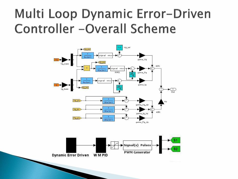

Comprising two blocks whose outputs are indicated by e(A) and e(b):
1. Dynamic Tracking Regulator:
Voltage error between instantaneous and reference voltage
Stabilizer current excursion loop
Limiting generator power excursion loop
2. Minimal Ripple Regulator:
Minimizing ripple and abrupt change in generator voltage
Minimizing ripple and abrupt change in generator current
Minimizing ripple and abrupt change in generator power

Weighted Modified PID Controller including an error sequential activation supplementary loop to ensure fast dynamic response in large-load-excursion circumstances

AC grid- Our Case Study
AC load

RMS Voltage- Generator
Normal Conditions
Simulation Results (Using MATLAB/SIMULINK)
0 0.2 0.4 0.6 0.8 10
0.5
1
1.5
Time (sec)
RM
S V
olt
ag
e (
pu
)
Basic Scheme Proposed Scheme
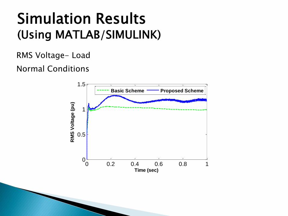
Simulation Results (Using MATLAB/SIMULINK)
RMS Voltage- Load
Normal Conditions
0 0.2 0.4 0.6 0.8 10
0.5
1
1.5
Time (sec)
RM
S V
olt
ag
e (
pu
)
Basic Scheme Proposed Scheme

Simulation Results (Using MATLAB/SIMULINK)
RMS Voltage- Infinite Bus
Normal Conditions
0 0.2 0.4 0.6 0.8 10
0.5
1
1.5
Time (sec)
RM
S V
olt
ag
e (
pu
)
Basic Scheme Proposed Scheme
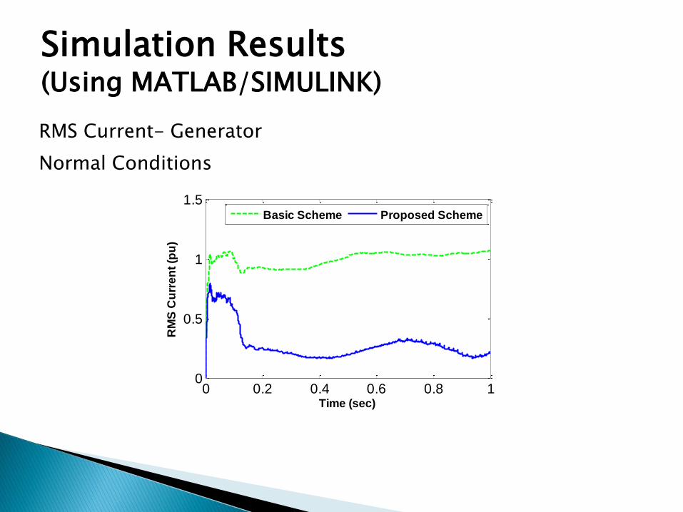
Simulation Results (Using MATLAB/SIMULINK)
RMS Current- Generator
Normal Conditions
0 0.2 0.4 0.6 0.8 10
0.5
1
1.5
Time (sec)
RM
S C
urr
en
t (p
u)
Basic Scheme Proposed Scheme

Simulation Results (Using MATLAB/SIMULINK)
RMS Current- Load
Normal Conditions
0 0.2 0.4 0.6 0.8 10
0.2
0.4
0.6
0.8
1
Time (sec)
RM
S C
urr
en
t (p
u)
Basic Scheme Proposed Scheme

Simulation Results (Using MATLAB/SIMULINK)
RMS Current- Infinite Bus
Normal Conditions
0 0.2 0.4 0.6 0.8 10
0.5
1
1.5
Time (sec)
RM
S C
urr
en
t (p
u)
Basic Scheme Proposed Scheme

Simulation Results (Using MATLAB/SIMULINK)
Active Power- Generator
Normal Conditions
0 0.2 0.4 0.6 0.8 1-0.5
0
0.5
1
1.5
2
Time (sec)
Ac
tiv
e P
ow
er
(pu
)
Basic Scheme Proposed Scheme

Simulation Results (Using MATLAB/SIMULINK)
Active Power- Load
Normal Conditions
0 0.2 0.4 0.6 0.8 1-0.2
0
0.2
0.4
0.6
Time (sec)
Ac
tiv
e P
ow
er
(pu
)
Basic Scheme Proposed Scheme

Simulation Results (Using MATLAB/SIMULINK)
Active Power- Infinite Bus
Normal Conditions
0 0.2 0.4 0.6 0.8 1
-1
-0.5
0
0.5
1
Time (sec)
Ac
tiv
e P
ow
er
(pu
)
Basic Scheme Proposed Scheme

Simulation Results (Using MATLAB/SIMULINK)
Reactive Power- Generator
Normal Conditions
0 0.2 0.4 0.6 0.8 1-0.5
0
0.5
1
1.5
Time (sec)
Re
ac
tiv
e P
ow
er
(pu
)
Basic Scheme Proposed Scheme

Simulation Results (Using MATLAB/SIMULINK)
Reactive Power- Load
Normal Conditions
0 0.2 0.4 0.6 0.8 1-0.5
0
0.5
1
1.5
Time (sec)
Re
ac
tiv
e P
ow
er
(pu
)
Basic Scheme Proposed Scheme

Simulation Results (Using MATLAB/SIMULINK)
Reactive Power- Infinite Bus
Normal Conditions
0 0.2 0.4 0.6 0.8 1-1.5
-1
-0.5
0
0.5
Time (sec)
Re
ac
tiv
e P
ow
er
(pu
)
Basic Scheme Proposed Scheme

Simulation Results (Using MATLAB/SIMULINK)
Power Factor- Generator
Normal Conditions
0 0.2 0.4 0.6 0.8 1-0.5
0
0.5
1
1.5
Time (sec)
Po
we
r F
ac
tor
Basic Scheme Proposed Scheme
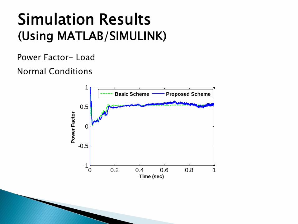
Simulation Results (Using MATLAB/SIMULINK)
Power Factor- Load
Normal Conditions
0 0.2 0.4 0.6 0.8 1-1
-0.5
0
0.5
1
Time (sec)
Po
we
r F
ac
tor
Basic Scheme Proposed Scheme

Simulation Results (Using MATLAB/SIMULINK)
Power Factor- Infinite Bus
Normal Conditions
0 0.2 0.4 0.6 0.8 1-1
-0.5
0
0.5
1
Time (sec)
Po
we
r F
ac
tor
Basic Scheme Proposed Scheme

Simulation Results (Using MATLAB/SIMULINK)
THD- Voltage- Generator
Normal Conditions
2 3 4 5 6 7 8 9 10 11 12 13 14 150
2
4
6
8
Harmonic Order
Basic Scheme THD=7.94
Proposed Scheme THD=6.95

Simulation Results (Using MATLAB/SIMULINK)
THD- Voltage- Load
Normal Conditions
2 3 4 5 6 7 8 9 10 11 12 13 14 150
2
4
6
8
Harmonic Order
Basic Scheme THD=7.94
Proposed Scheme THD=6.95

Simulation Results (Using MATLAB/SIMULINK)
THD- Current- Generator
Normal Conditions
2 3 4 5 6 7 8 9 10 11 12 13 14 150
5
10
15
20
Harmonic Order
Basic Scheme THD=29.82
Proposed Scheme THD=10.64
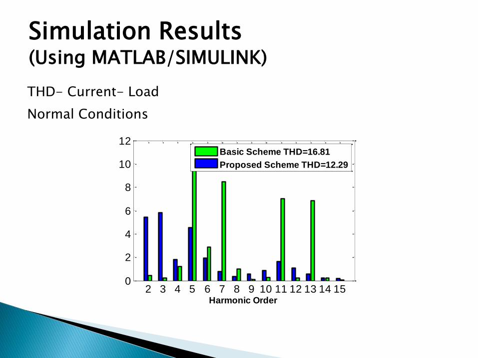
Simulation Results (Using MATLAB/SIMULINK)
THD- Current- Load
Normal Conditions
2 3 4 5 6 7 8 9 10 11 12 13 14 150
2
4
6
8
10
12
Harmonic Order
Basic Scheme THD=16.81
Proposed Scheme THD=12.29

Simulation Results (Using MATLAB/SIMULINK)
THD- Current- Infinite Bus
Normal Conditions
2 3 4 5 6 7 8 9 10 11 12 13 14 150
5
10
15
20
25
Harmonic Order
Basic Scheme THD=25.12
Proposed Scheme THD=2.82

Simulation Results (Using
MATLAB/SIMULINK)
Fault Conditions
A 3-Phase Short Circuit occurs in VB1 Busbar at 0.2 sec and would be cleared after 0.1 sec

Simulation Results (Using MATLAB/SIMULINK)
RMS Voltage- Generator
Fault Conditions
0 0.2 0.4 0.60
0.5
1
1.5
Time (sec)
RM
S V
olt
ag
e (
pu
)
Basic Scheme Proposed Scheme

Simulation Results (Using MATLAB/SIMULINK)
RMS Voltage- Load
Fault Conditions
0 0.2 0.4 0.60
0.5
1
1.5
Time (sec)
RM
S V
olt
ag
e (
pu
)
Basic Scheme Proposed Scheme

Simulation Results (Using MATLAB/SIMULINK)
RMS Current- Generator
Fault Conditions
0 0.2 0.4 0.60
2
4
6
8
Time (sec)
RM
S C
urr
en
t (p
u)
Basic Scheme Proposed Scheme

Simulation Results (Using MATLAB/SIMULINK)
RMS Current- Load
Fault Conditions
0 0.2 0.4 0.60
0.2
0.4
0.6
0.8
1
Time (sec)
RM
S C
urr
en
t (p
u)
Basic Scheme Proposed Scheme

Simulation Results (Using MATLAB/SIMULINK)
RMS Current- Infinite Bus
Fault Conditions
0 0.2 0.4 0.60
2
4
6
8
Time (sec)
RM
S C
urr
en
t (p
u)
Basic Scheme Proposed Scheme

Simulation Results (Using
MATLAB/SIMULINK)
Hybrid-Load Excursion Conditions
At 0.1 sec, linear load is disconnected and reconnected after 0.05 sec. At 0.2 sec, nonlinear load is disconnected and reconnected after 0.05 sec. At 0.3 sec, load motor torque is decreased by 50% for duration of 0.05 sec. At 0.4 sec, load motor torque is increased by 50% for duration of 0.05 sec.

Simulation Results (Using MATLAB/SIMULINK)
RMS Voltage- Generator
Load Excursion- Conditions
0 0.2 0.4 0.60
0.5
1
1.5
Time (sec)
RM
S V
olt
ag
e (
pu
)
Basic Scheme Proposed Scheme

Simulation Results (Using MATLAB/SIMULINK)
RMS Voltage- Load
Load Excursion- Conditions
0 0.2 0.4 0.60
0.5
1
1.5
Time (sec)
RM
S V
olt
ag
e (
pu
)
Basic Scheme Proposed Scheme

Simulation Results (Using MATLAB/SIMULINK)
RMS Voltage- Infinite Bus
Load Excursion- Conditions
0 0.2 0.4 0.60
0.5
1
1.5
Time (sec)
RM
S V
olt
ag
e (
pu
)
Basic Scheme Proposed Scheme

Simulation Results (Using MATLAB/SIMULINK)
RMS Current- Generator
Load Excursion- Conditions
0 0.2 0.4 0.60
0.5
1
1.5
Time (sec)
RM
S C
urr
en
t (p
u)
Basic Scheme Proposed Scheme

Simulation Results (Using MATLAB/SIMULINK)
RMS Current- Load
Load Excursion- Conditions
0 0.2 0.4 0.60
0.2
0.4
0.6
0.8
1
Time (sec)
RM
S C
urr
en
t (p
u)
Basic Scheme Proposed Scheme
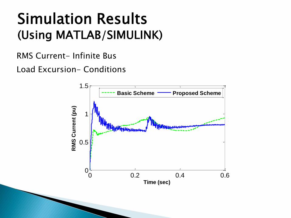
Simulation Results (Using MATLAB/SIMULINK)
RMS Current- Infinite Bus
Load Excursion- Conditions
0 0.2 0.4 0.60
0.5
1
1.5
Time (sec)
RM
S C
urr
en
t (p
u)
Basic Scheme Proposed Scheme

A novel FACTS-based device, Modulated Filter Compensation Scheme
Dynamic multi-loop error driven controller for effective Pulsing of Solid State switched
The Switched Filter-Compensation Scheme is effective in Voltage Stabilization, Loss Reduction on Feeder, Efficient Energy Utilization and Power Factor improvement under:
1. Normal Operation
2. Fault Conditions
3. Hybrid- Load Excursions

Any Question?