Embed Size (px)
Citation preview
Addressing Modes and Assembly Language
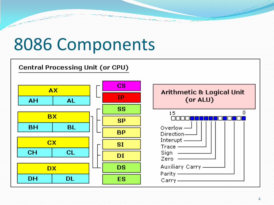
8086 Components
2
Introduction Efficient software development for the microprocessor
requires a complete familiarity with the addressing modes employed by each instruction.
3
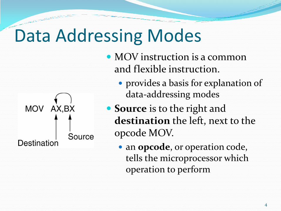
Data Addressing Modes MOV instruction is a common
and flexible instruction.
provides a basis for explanation of data-addressing modes
Source is to the right and destination the left, next to the opcode MOV.
an opcode, or operation code, tells the microprocessor which operation to perform
4
5
Addressing Mode An addressing mode specifies how to calculate the
effective memory address of an operand by using information held in registers and/or constants contained within a machine instruction or elsewhere.
6
1. Register Addressing In this mode the source operand, destination operand
or both are to be contained in the 8086 register.
MOV DX, CX
MOV CL, DL
8-bit registers: AH, AL, BH, BL, CH, CL, DH, and DL.
16-bit registers: AX, BX, CX, DX, SP, BP, SI, and DI.
never mix an 8-bit \with a 16-bit register.
7
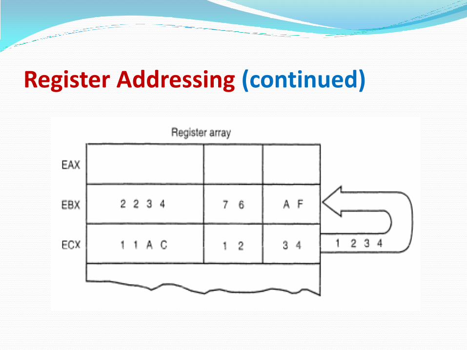
Register Addressing (continued)
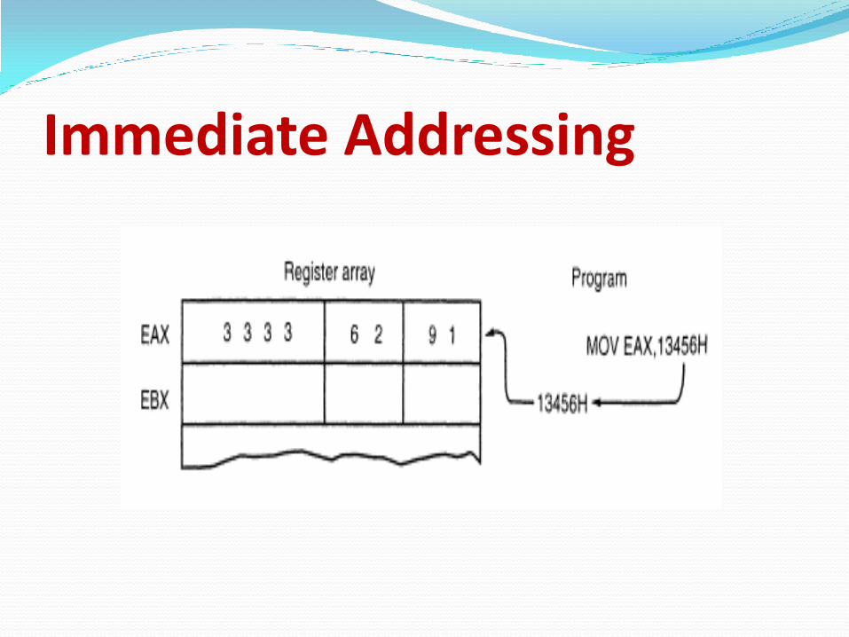
2. Immediate Addressing Transfers the source-immediate byte or word of data
into the destination register or memory location.
MOV CL, 03H
MOV DX, 0502H
Term immediate implies that data immediately follow the hexadecimal opcode in the memory.
immediate data are constant data
data transferred from a register or memory location are variable data
9
Immediate Addressing
Immediate Addressing (continued) The letter H appends hexadecimal data.
If hexadecimal data begin with a letter, the assembler requires the data start with a 0.
to represent a hexadecimal F2, 0F2H is used in assembly language
Decimal data are represented as is and require no special codes or adjustments.
an example is the 100 decimal in the MOV AL,100 instruction
11

An Assembly Program DATA1 DB 23H ;define DATA1 as a byte of 23H
DATA2 DW 1000H ;define DATA2 as a word of 1000H
START: MOV AL,BL ;copy BL into AL
MOV BH,AL ;copy AL into BH
MOV CX,200 ;copy 200 decimal into CX
12
Assembly Programs Each statement in an assembly language program
consists of four parts or fields.
The leftmost field is called the label. used to store a symbolic name for the memory location
it represents
All labels must begin with a letter or one of the following special characters: @, $, -, or ?.
a label may any length from 1 to 35 characters
The label appears in a program to identify the name of a memory location for storing data and for other purposes.
13
Assembly Language (continued) The next field to the right is the opcode field.
designed to hold the instruction, or opcode
the MOV part of the move data instruction is an example of an opcode
Right of the opcode field is the operand field. contains information used by the opcode
the MOV AL,BL instruction has the opcode MOV and operands AL and BL
The comment field, the final field, contains a comment about the instruction(s). comments always begin with a semicolon (;)
14
3. Direct Addressing Moves a byte or word between a memory location and
a register. The instruction set does not support a memory-to-memory transfer, except for the MOVS instruction.
Examples:
MOV CX,START
MOV START,BL
START can be defined as an address by using the assembler DB(Define Byte) or DW(Define Word) pseudo instructions.
15
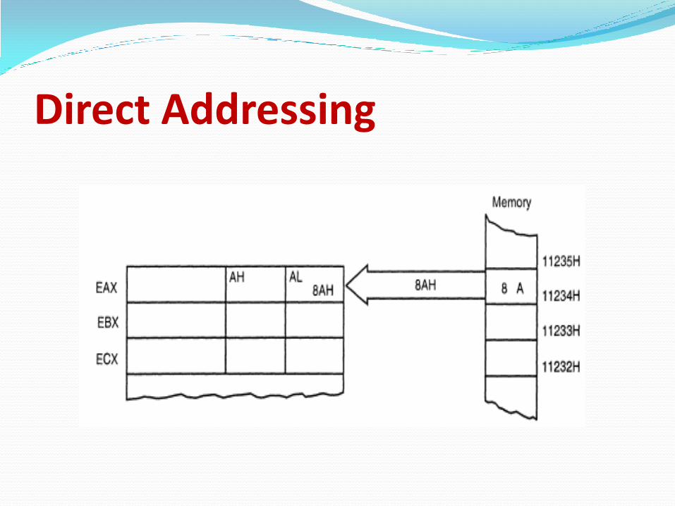
Direct Addressing
4. Register Indirect Addressing Transfers a byte or word between a register and a
memory location addressed by an index or base register. The index and base registers are BP, BX, DI, and SI.
Example: MOV AX,[BX] instruction copies the word-sized data from the data segment offset address indexed by BX into register AX.
17
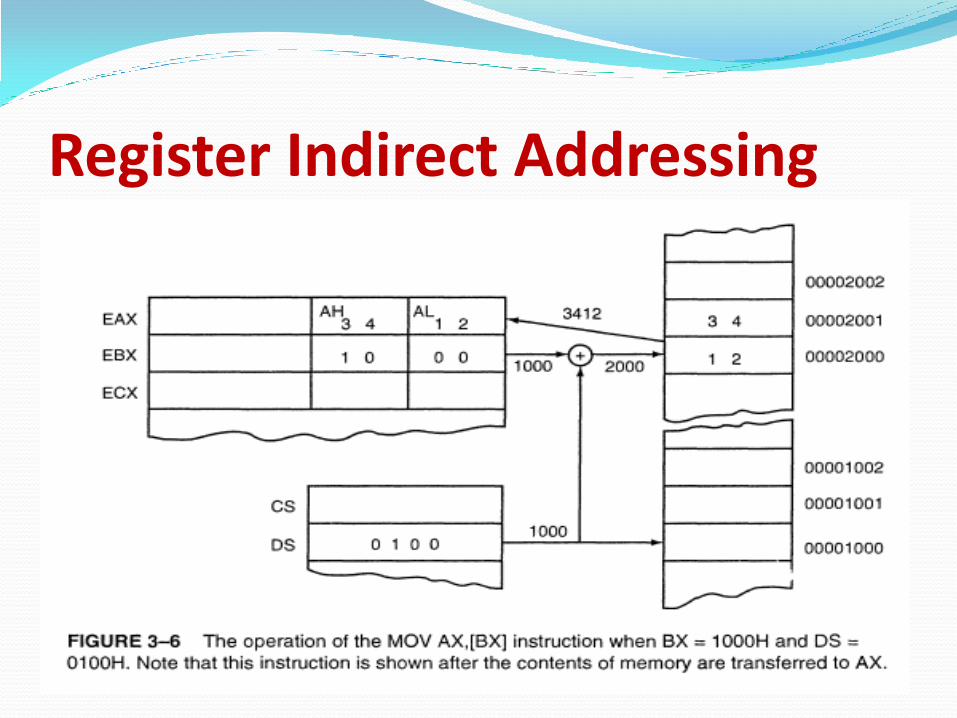
Register Indirect Addressing

Register Indirect Addressing
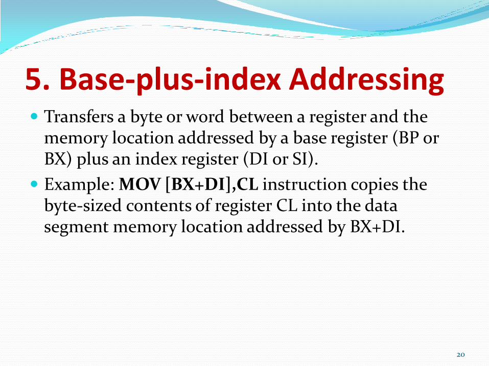
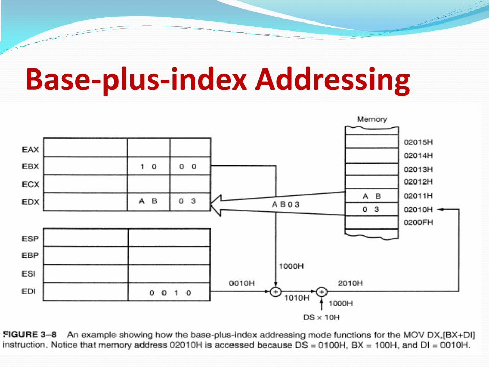
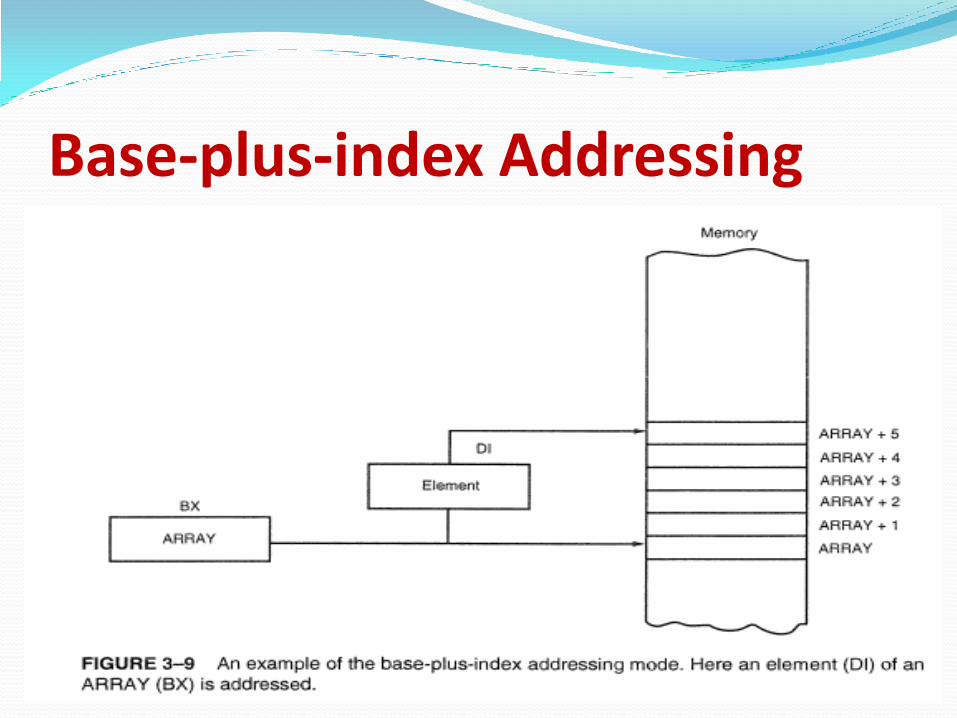
5. Base-plus-index Addressing Transfers a byte or word between a register and the
memory location addressed by a base register (BP or BX) plus an index register (DI or SI).
Example: MOV [BX+DI],CL instruction copies the byte-sized contents of register CL into the data segment memory location addressed by BX+DI.
20
Base-plus-index Addressing
Base-plus-index Addressing
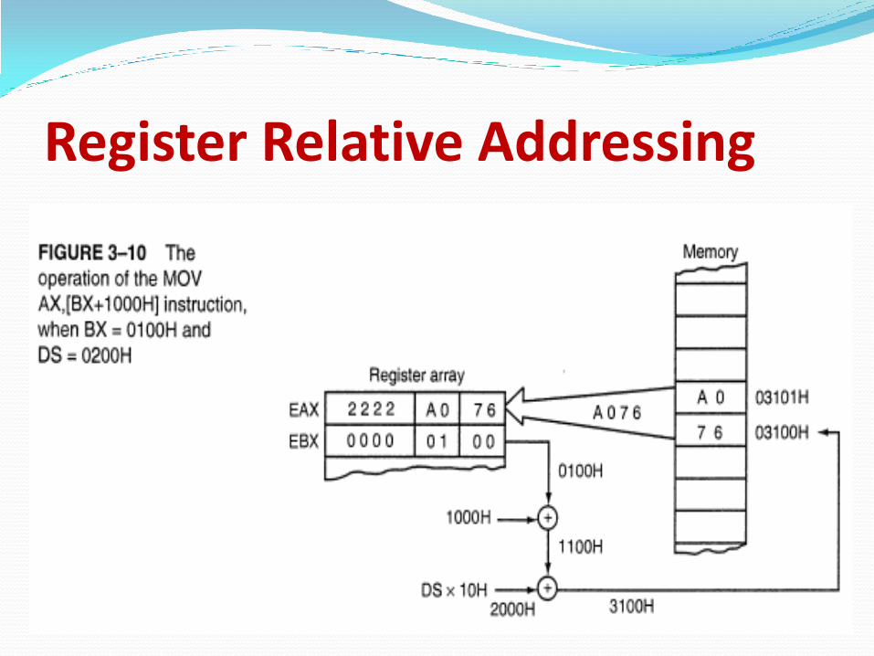
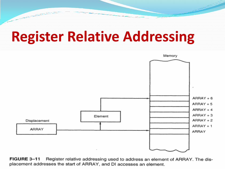
6. Register Relative Addressing Moves a byte or word between a register and the
memory location addressed by an index or base register plus a displacement.
Examples:
MOV AX,[BX+4]
MOV AX,ARRAY[BX]
23
Register Relative Addressing
Register Relative Addressing

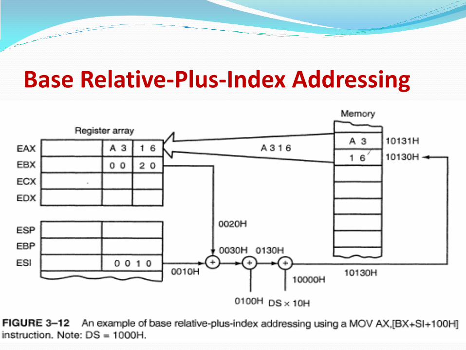
7. Base Relative-Plus-Index Addressing Transfers a byte or word between a register and the
memory location addressed by a base and an index register plus a displacement.
Examples:
MOV AX,ARRAY[BX+DI]
MOV AX,[BX+DI+4]
26
Base Relative-Plus-Index Addressing

Base Relative-Plus-Index Addressing
8. Relative Addressing In this mode, the operand is specified as a signed 8 bit
displacement, relative to PC (Program Counter).
Example: JMP START
PC is loaded with current PC contents plus the 8 bit signed value of START, otherwise the next instruction is executed.
29
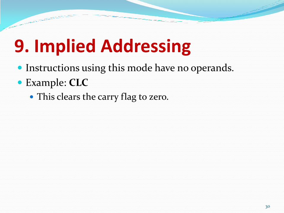
9. Implied Addressing Instructions using this mode have no operands.
Example: CLC
This clears the carry flag to zero.
30
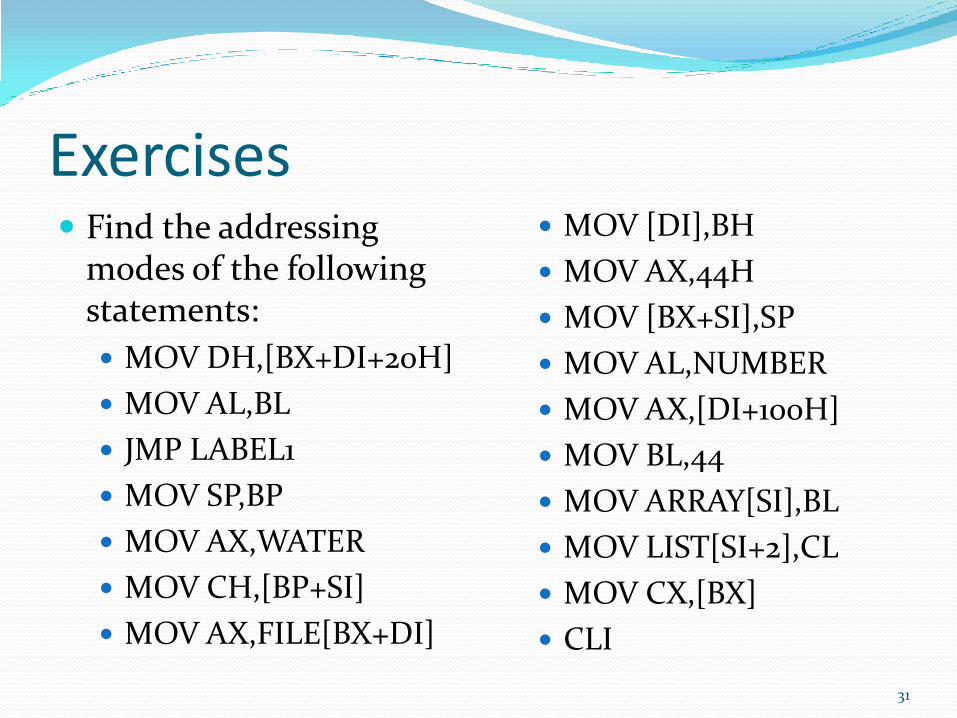
Exercises Find the addressing
modes of the following statements:
MOV DH,[BX+DI+20H]
MOV AL,BL
JMP LABEL1
MOV SP,BP
MOV AX,WATER
MOV CH,[BP+SI]
MOV AX,FILE[BX+DI]
MOV [DI],BH
MOV AX,44H
MOV [BX+SI],SP
MOV AL,NUMBER
MOV AX,[DI+100H]
MOV BL,44
MOV ARRAY[SI],BL
MOV LIST[SI+2],CL
MOV CX,[BX]
CLI
31
PUSH POP Instructions The PUSH POP instructions are important
instructions that store and retrive the data from a LIFO (Last In First Out) stack memory
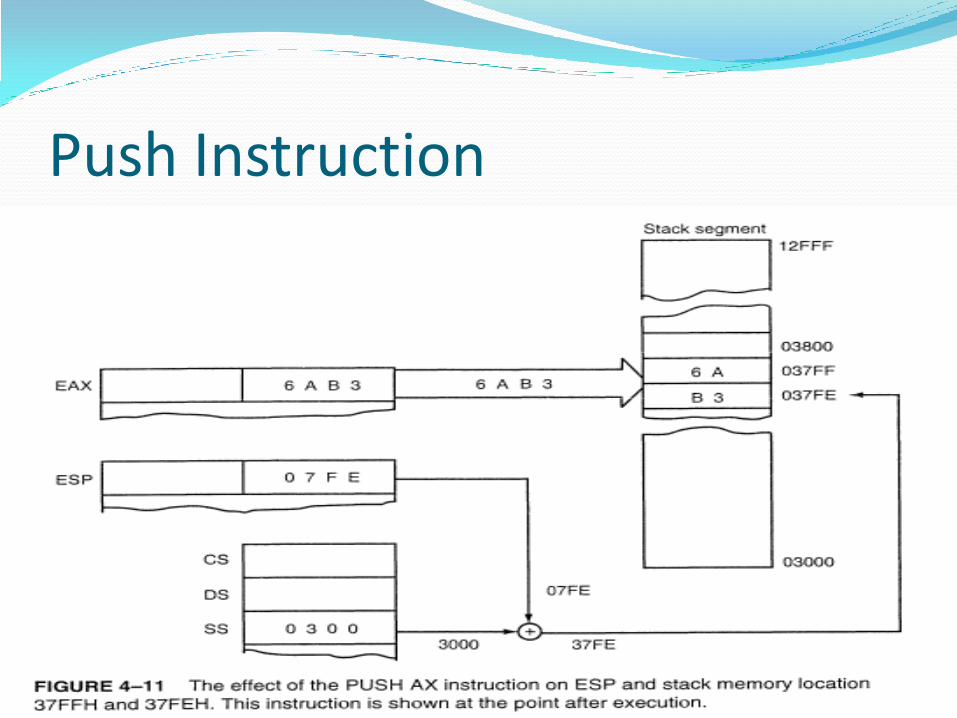
Push Instruction
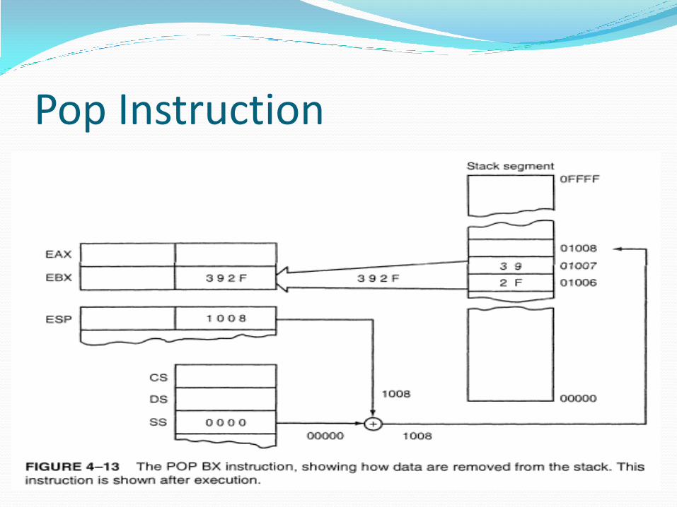
Pop Instruction
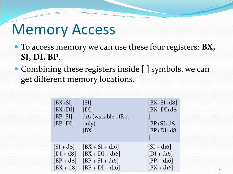
Memory Access To access memory we can use these four registers: BX,
SI, DI, BP.
Combining these registers inside [ ] symbols, we can get different memory locations.
35
[BX+SI] [BX+DI] [BP+SI] [BP+DI]
[SI] [DI] d16 (variable offset only) [BX]
[BX+SI+d8] [BX+DI+d8] [BP+SI+d8] [BP+DI+d8]
[SI + d8] [DI + d8] [BP + d8] [BX + d8]
[BX + SI + d16] [BX + DI + d16] [BP + SI + d16] [BP + DI + d16]
[SI + d16] [DI + d16] [BP + d16] [BX + d16]
Displacements • d8 - stays for 8 bit signed immediate displacement (for
example: 22, 55h, -1, etc...) • d16 - stays for 16 bit signed immediate displacement (for
example: 300, 5517h, -259, etc...). • Displacement can be an immediate value or offset of a
variable, or even both (If there are several values, assembler evaluates all values and calculates a single immediate value).
• Displacement can be inside or outside of the [ ] symbols, assembler generates the same machine code for both ways.
• Displacement is a signed value, so it can be both positive or negative.
• Generally the compiler takes care about difference between d8 and d16, and generates the required machine code.
36
Example Let's assume that DS = 100, BX = 30, SI = 70.
[BX + SI] + 25 is calculated by processor to this physical address: 100 * 16 + 30 + 70 + 25 = 1725.
(note that all addresses are in decimal form, not hexadecimal, so DS is multiplied by 16=10H)
37
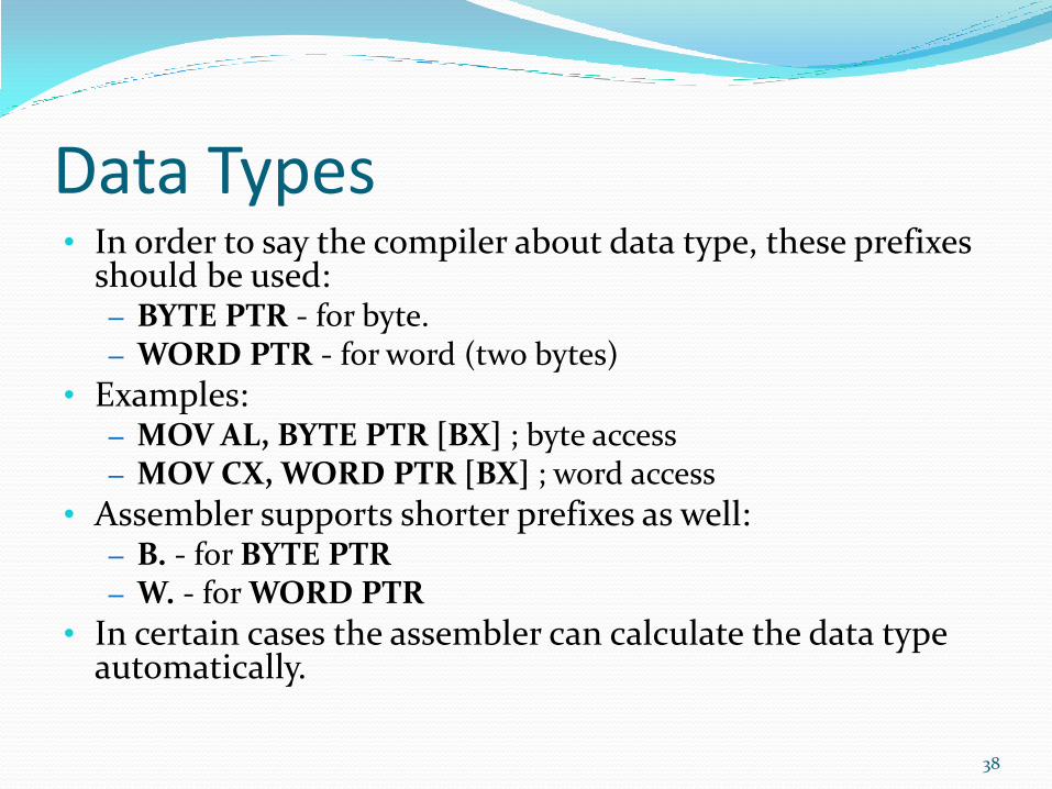
Data Types • In order to say the compiler about data type, these prefixes
should be used: – BYTE PTR - for byte. – WORD PTR - for word (two bytes)
• Examples: – MOV AL, BYTE PTR [BX] ; byte access – MOV CX, WORD PTR [BX] ; word access
• Assembler supports shorter prefixes as well: – B. - for BYTE PTR – W. - for WORD PTR
• In certain cases the assembler can calculate the data type automatically.
38
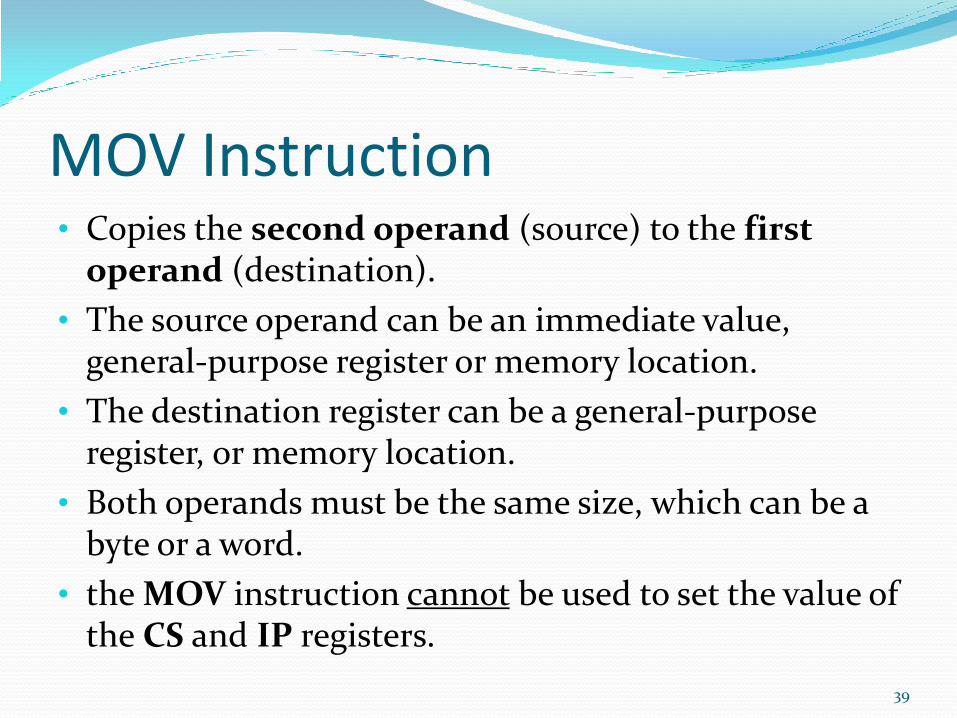
MOV Instruction • Copies the second operand (source) to the first
operand (destination).
• The source operand can be an immediate value, general-purpose register or memory location.
• The destination register can be a general-purpose register, or memory location.
• Both operands must be the same size, which can be a byte or a word.
• the MOV instruction cannot be used to set the value of the CS and IP registers.
39
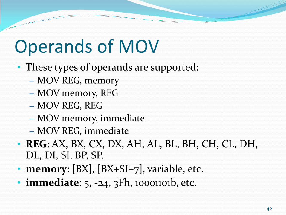
Operands of MOV • These types of operands are supported:
– MOV REG, memory
– MOV memory, REG
– MOV REG, REG
– MOV memory, immediate
– MOV REG, immediate
• REG: AX, BX, CX, DX, AH, AL, BL, BH, CH, CL, DH, DL, DI, SI, BP, SP.
• memory: [BX], [BX+SI+7], variable, etc.
• immediate: 5, -24, 3Fh, 10001101b, etc.
40
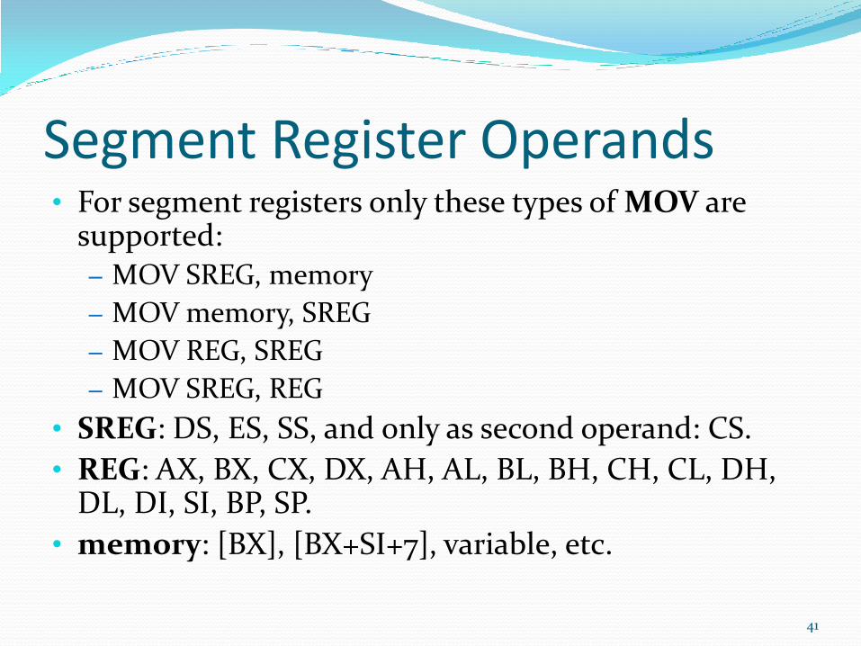
Segment Register Operands • For segment registers only these types of MOV are
supported: – MOV SREG, memory
– MOV memory, SREG
– MOV REG, SREG
– MOV SREG, REG
• SREG: DS, ES, SS, and only as second operand: CS.
• REG: AX, BX, CX, DX, AH, AL, BL, BH, CH, CL, DH, DL, DI, SI, BP, SP.
• memory: [BX], [BX+SI+7], variable, etc.
41
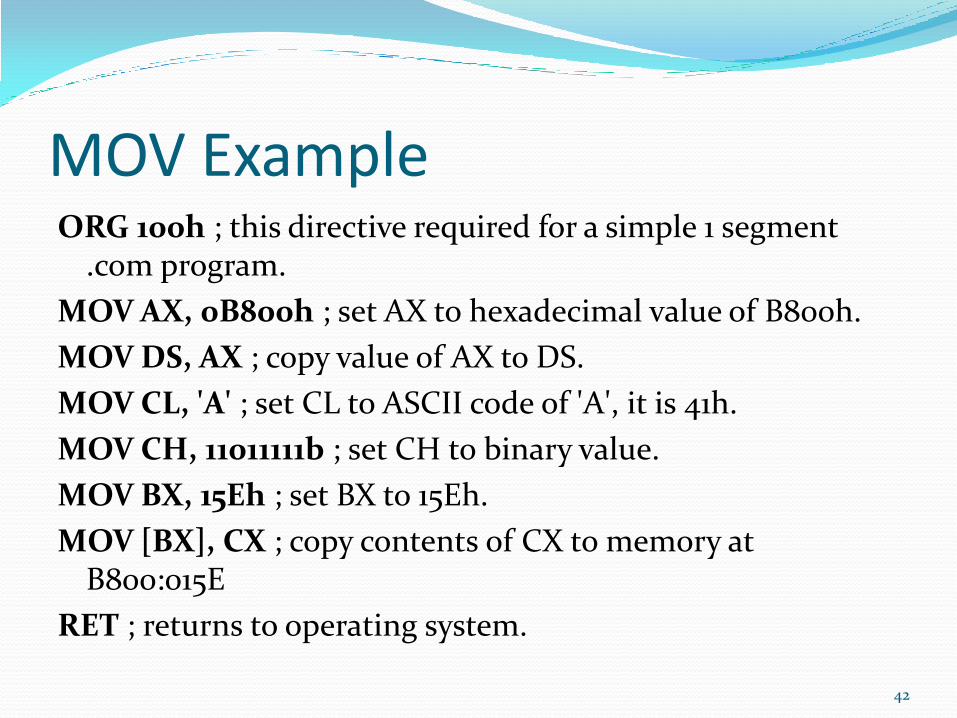
MOV Example ORG 100h ; this directive required for a simple 1 segment
.com program.
MOV AX, 0B800h ; set AX to hexadecimal value of B800h.
MOV DS, AX ; copy value of AX to DS.
MOV CL, 'A' ; set CL to ASCII code of 'A', it is 41h.
MOV CH, 11011111b ; set CH to binary value.
MOV BX, 15Eh ; set BX to 15Eh.
MOV [BX], CX ; copy contents of CX to memory at B800:015E
RET ; returns to operating system.
42
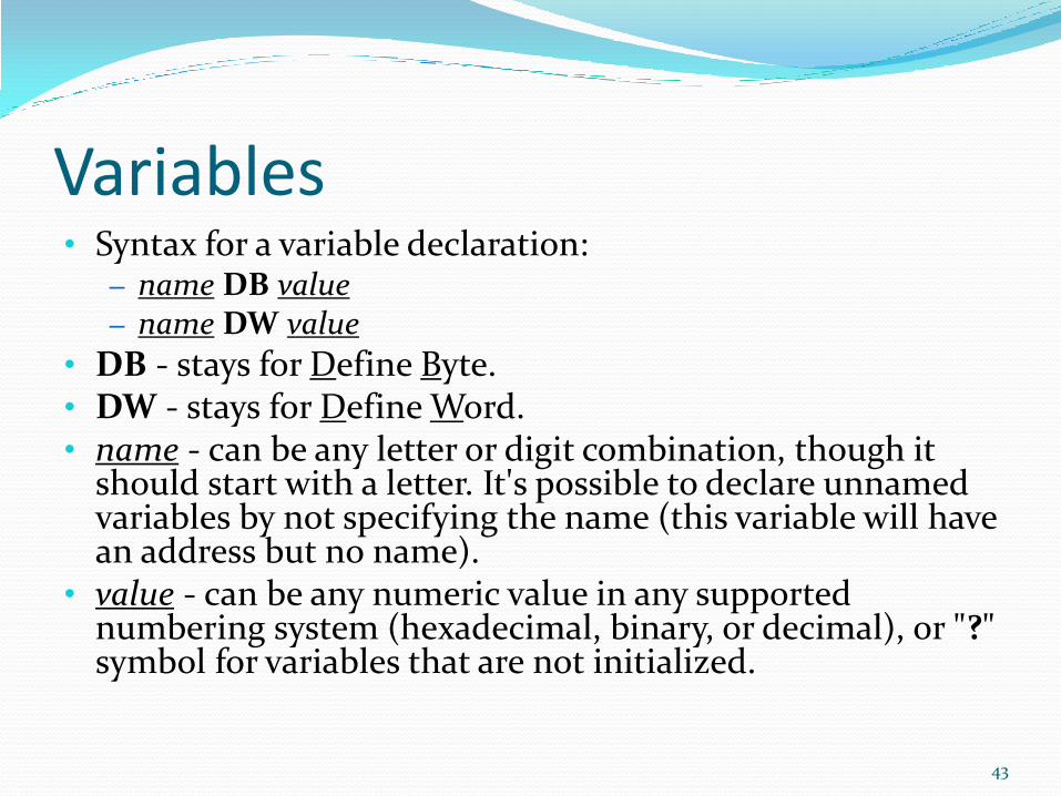
Variables • Syntax for a variable declaration:
– name DB value – name DW value
• DB - stays for Define Byte. • DW - stays for Define Word. • name - can be any letter or digit combination, though it
should start with a letter. It's possible to declare unnamed variables by not specifying the name (this variable will have an address but no name).
• value - can be any numeric value in any supported numbering system (hexadecimal, binary, or decimal), or "?" symbol for variables that are not initialized.
43
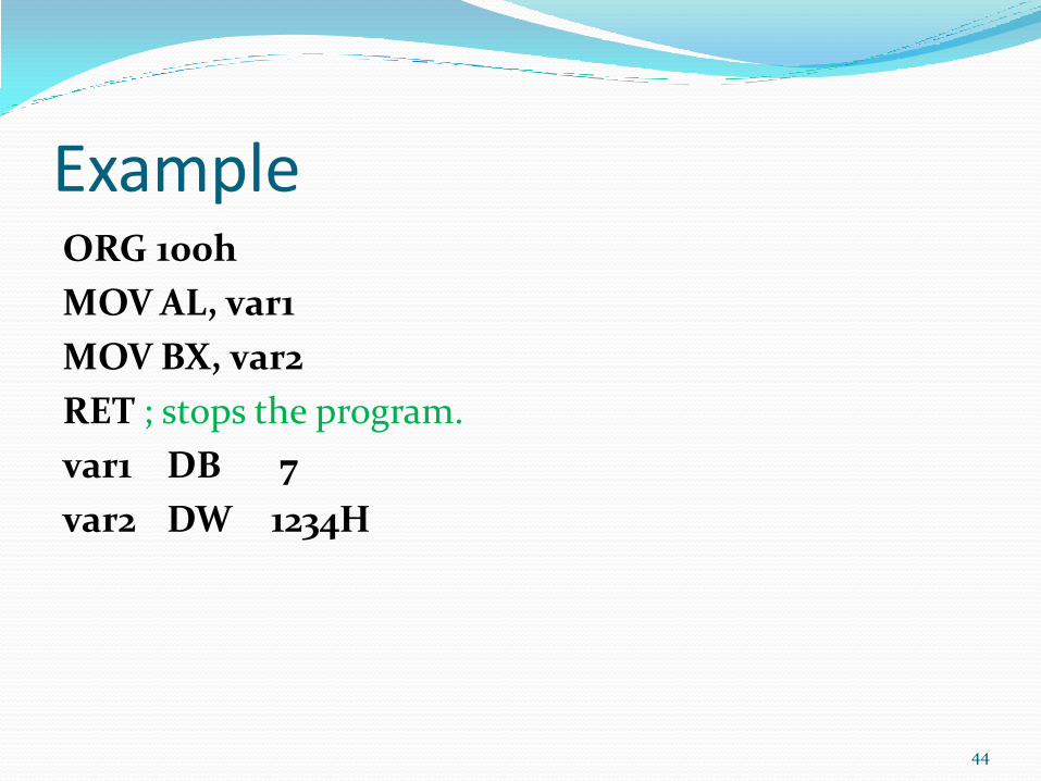
Example ORG 100h
MOV AL, var1
MOV BX, var2
RET ; stops the program.
var1 DB 7
var2 DW 1234H
44
ORG Directive • ORG 100h is a compiler directive (it tells compiler how
to handle the source code).
• It tells compiler that the executable file will be loaded at the offset of 100h (256 bytes), so compiler should calculate the correct address for all variables when it replaces the variable names with their offsets.
• Directives are never converted to any real machine code.
• Operating system keeps some data about the program in the first 256 bytes of the CS (code segment), such as command line parameters and etc.
45
Arrays Arrays can be seen as chains of variables.
A text string is an example of a byte array, each character is presented as an ASCII code value (0..255).
Examples:
a DB 48h, 65h, 6Ch, 6Ch, 6Fh, 00h
b DB 'Hello', 0
b is an exact copy of the a array, when compiler sees a string inside quotes it automatically converts it to set of bytes.
46

Accessing Array Elements
You can access the value of any element in array using square brackets, for example:
MOV AL, a[3]
You can also use any of the memory index registers BX, SI, DI, BP, for example:
MOV SI, 3
MOV AL, a[SI] 47
Declaring Large Arrays If you need to declare a large array you can
use DUP operator.
The syntax for DUP:
number DUP ( value(s) )
number - number of duplicate to make (any constant value).
value - expression that DUP will duplicate.
Example:
c DB 5 DUP(9)
is an alternative way of declaring:
c DB 9, 9, 9, 9, 9
48
Declaring Large Arrays One more example:
d DB 5 DUP(1, 2)
is an alternative way of declaring:
d DB 1, 2, 1, 2, 1, 2, 1, 2, 1, 2
49
Getting the Address of a Variable
The LEA instruction and the OFFSET operator can be used to get the offset address of a variable.
LEA is more powerful because it also allows you to get the address of an indexed variables.
Getting the address of the variable can be very useful in some situations, for example when you need to pass parameters to a procedure.
50
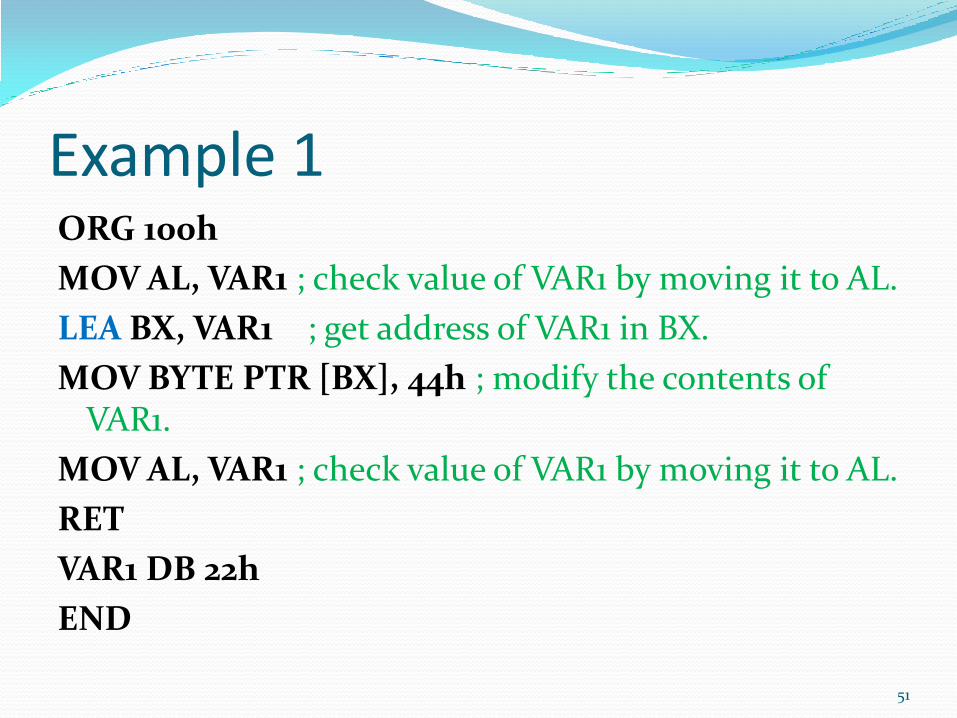
Example 1 ORG 100h
MOV AL, VAR1 ; check value of VAR1 by moving it to AL.
LEA BX, VAR1 ; get address of VAR1 in BX.
MOV BYTE PTR [BX], 44h ; modify the contents of VAR1.
MOV AL, VAR1 ; check value of VAR1 by moving it to AL.
RET
VAR1 DB 22h
END
51

Example 2 ORG 100h
MOV AL, VAR1 ; check value of VAR1 by moving it to AL.
MOV BX, OFFSET VAR1 ; get address of VAR1 in BX.
MOV BYTE PTR [BX], 44h ; modify the contents of VAR1.
MOV AL, VAR1 ; check value of VAR1 by moving it to AL.
RET
VAR1 DB 22h
END
52
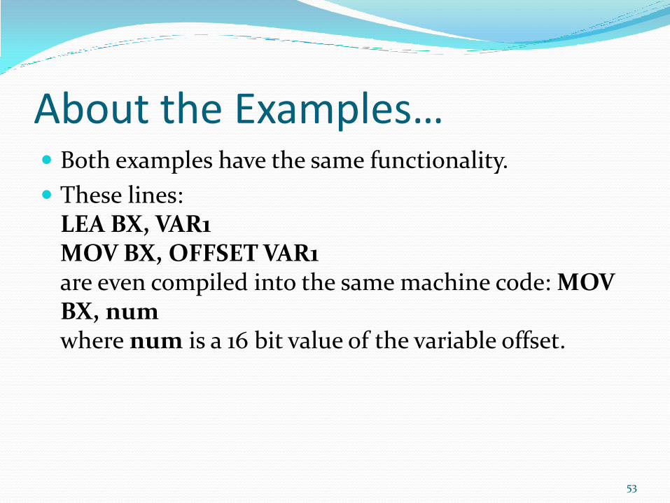
About the Examples… Both examples have the same functionality.
These lines: LEA BX, VAR1 MOV BX, OFFSET VAR1 are even compiled into the same machine code: MOV BX, num where num is a 16 bit value of the variable offset.
53

Constants Constants are just like variables, but they exist only until
your program is compiled (assembled).
After definition of a constant its value cannot be changed.
To define constants EQU directive is used:
name EQU < any expression >
Example:
k EQU 5
MOV AX, k
The above example is functionally identical to code:
MOV AX, 5
54
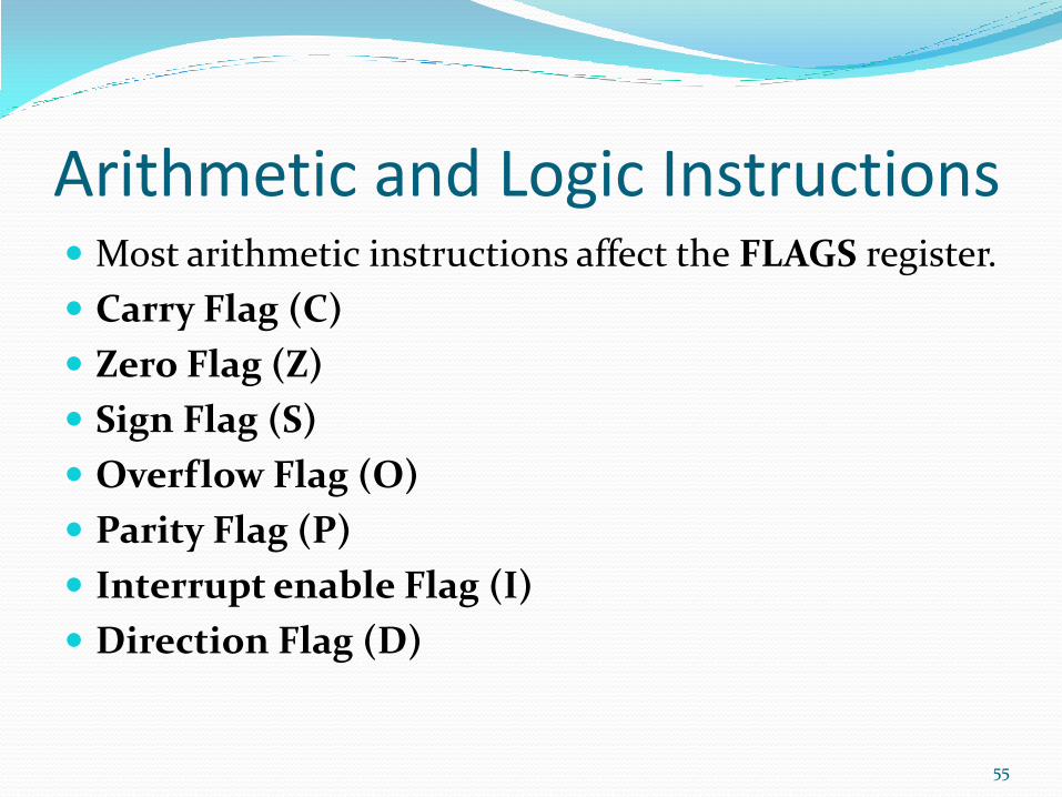
Arithmetic and Logic Instructions Most arithmetic instructions affect the FLAGS register.
Carry Flag (C)
Zero Flag (Z)
Sign Flag (S)
Overflow Flag (O)
Parity Flag (P)
Interrupt enable Flag (I)
Direction Flag (D)
55
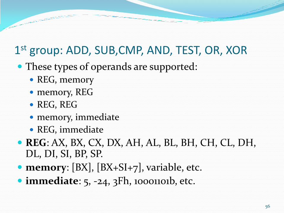
1st group: ADD, SUB,CMP, AND, TEST, OR, XOR
These types of operands are supported: REG, memory
memory, REG
REG, REG
memory, immediate
REG, immediate
REG: AX, BX, CX, DX, AH, AL, BL, BH, CH, CL, DH, DL, DI, SI, BP, SP.
memory: [BX], [BX+SI+7], variable, etc.
immediate: 5, -24, 3Fh, 10001101b, etc.
56
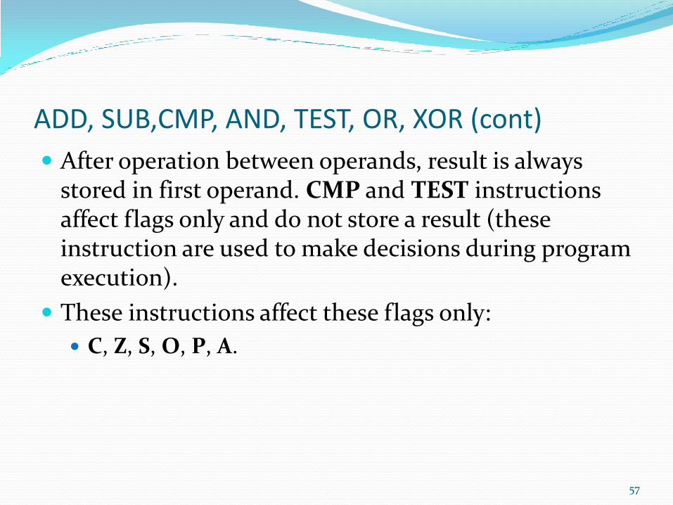
ADD, SUB,CMP, AND, TEST, OR, XOR (cont)
After operation between operands, result is always stored in first operand. CMP and TEST instructions affect flags only and do not store a result (these instruction are used to make decisions during program execution).
These instructions affect these flags only:
C, Z, S, O, P, A.
57
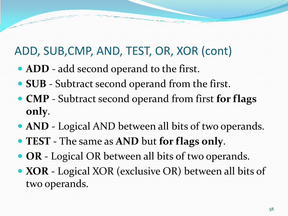
ADD, SUB,CMP, AND, TEST, OR, XOR (cont)
ADD - add second operand to the first.
SUB - Subtract second operand from the first.
CMP - Subtract second operand from first for flags only.
AND - Logical AND between all bits of two operands.
TEST - The same as AND but for flags only.
OR - Logical OR between all bits of two operands.
XOR - Logical XOR (exclusive OR) between all bits of two operands.
58
More About AND, OR, XOR AND operator gives 1 only if both operands are 1.
OR operator gives 1 if at least one operand is 1.
XOR operator gives 1 only if the operands are different.
59
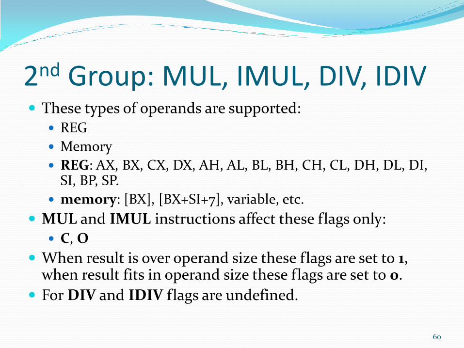
2nd Group: MUL, IMUL, DIV, IDIV These types of operands are supported:
REG
Memory
REG: AX, BX, CX, DX, AH, AL, BL, BH, CH, CL, DH, DL, DI, SI, BP, SP.
memory: [BX], [BX+SI+7], variable, etc.
MUL and IMUL instructions affect these flags only: C, O
When result is over operand size these flags are set to 1, when result fits in operand size these flags are set to 0.
For DIV and IDIV flags are undefined.
60
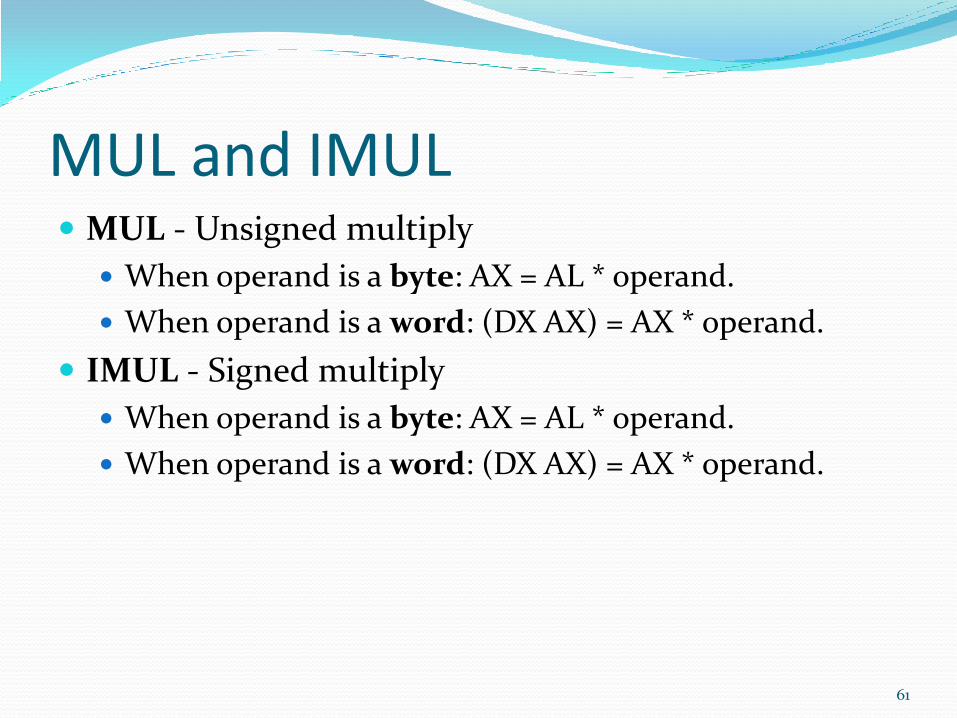
MUL and IMUL MUL - Unsigned multiply
When operand is a byte: AX = AL * operand.
When operand is a word: (DX AX) = AX * operand.
IMUL - Signed multiply
When operand is a byte: AX = AL * operand.
When operand is a word: (DX AX) = AX * operand.
61
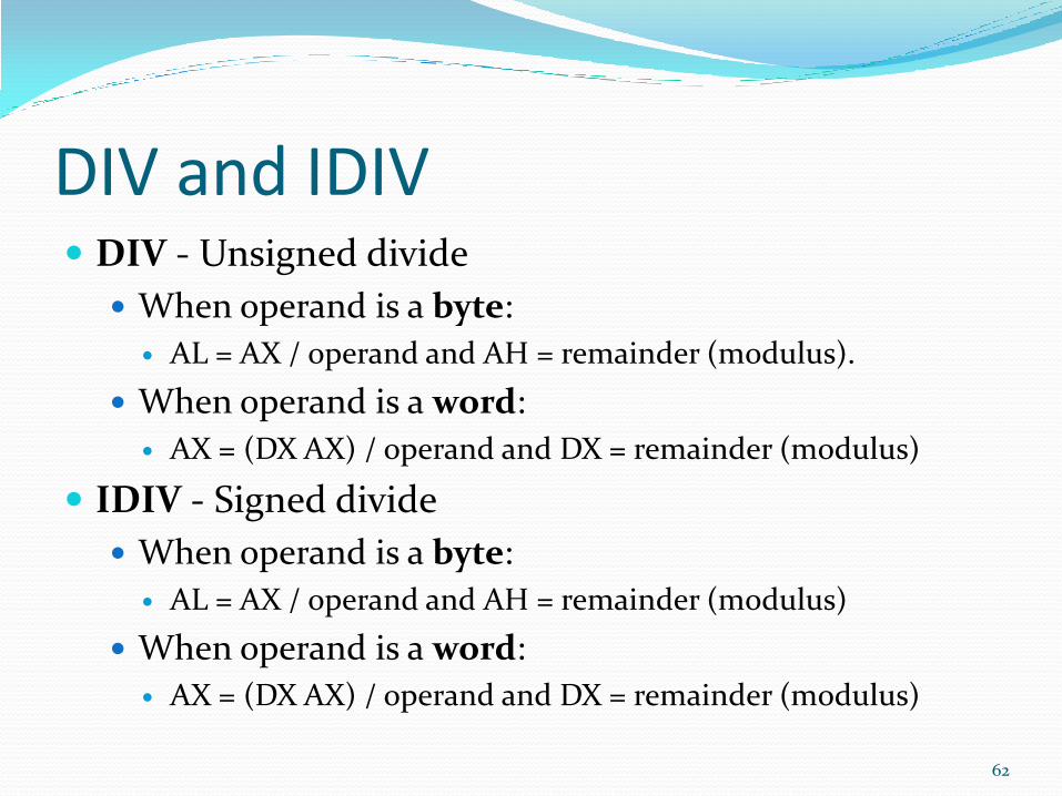
DIV and IDIV DIV - Unsigned divide
When operand is a byte:
AL = AX / operand and AH = remainder (modulus).
When operand is a word:
AX = (DX AX) / operand and DX = remainder (modulus)
IDIV - Signed divide
When operand is a byte:
AL = AX / operand and AH = remainder (modulus)
When operand is a word:
AX = (DX AX) / operand and DX = remainder (modulus)
62
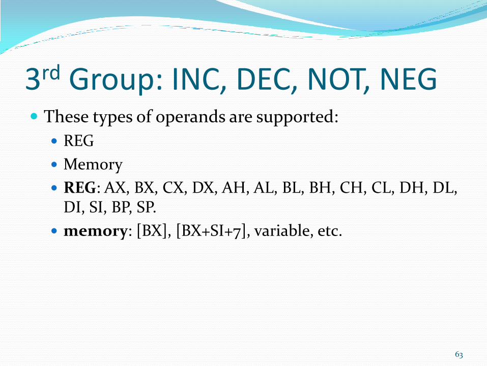
3rd Group: INC, DEC, NOT, NEG These types of operands are supported:
REG
Memory
REG: AX, BX, CX, DX, AH, AL, BL, BH, CH, CL, DH, DL, DI, SI, BP, SP.
memory: [BX], [BX+SI+7], variable, etc.
63
INC and DEC INC: Increments the operand by 1.
DEC: Decrements the operand by 1.
INC, DEC instructions affect these flags only:
Z, S, O, P, A
64
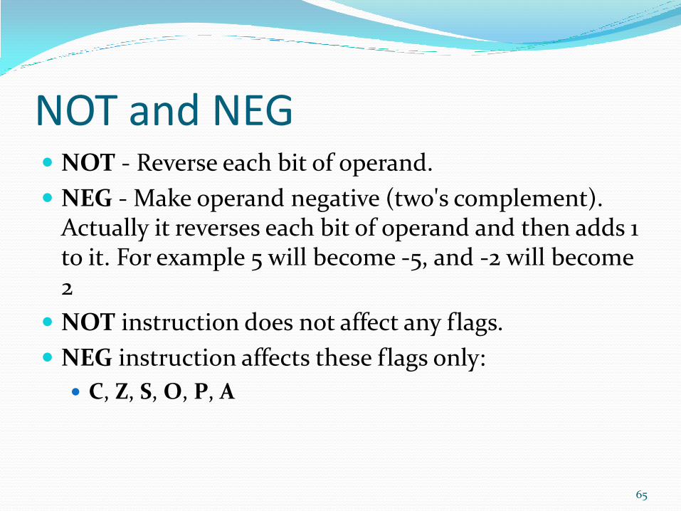
NOT and NEG NOT - Reverse each bit of operand.
NEG - Make operand negative (two's complement). Actually it reverses each bit of operand and then adds 1 to it. For example 5 will become -5, and -2 will become 2
NOT instruction does not affect any flags.
NEG instruction affects these flags only:
C, Z, S, O, P, A
65
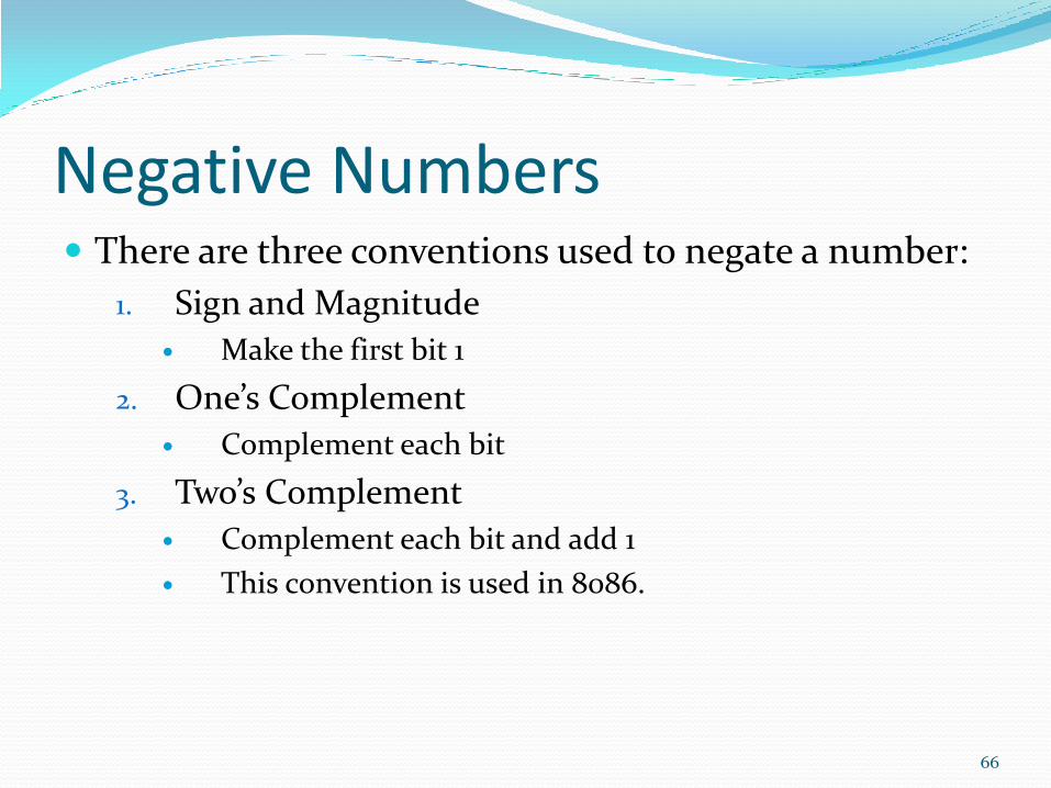
Negative Numbers There are three conventions used to negate a number:
1. Sign and Magnitude
Make the first bit 1
2. One’s Complement
Complement each bit
3. Two’s Complement
Complement each bit and add 1
This convention is used in 8086.
66
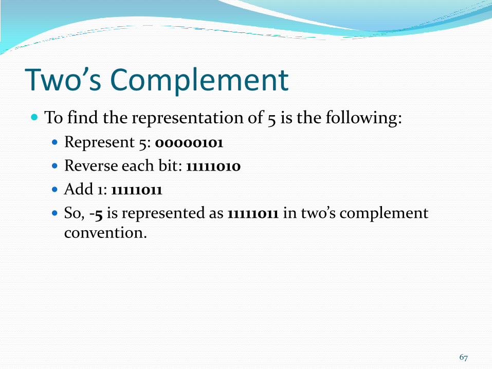
Two’s Complement To find the representation of 5 is the following:
Represent 5: 00000101
Reverse each bit: 11111010
Add 1: 11111011
So, -5 is represented as 11111011 in two’s complement convention.
67
Summary Addressing modes
Data movement Instructions
Arithmetic Instructions
Logic Instructions
Assembly Language Programming
Course Completed Chapter 3 4 and 5 Completed.