Embed Size (px)
Citation preview

26th Annual Conference on Fossil Energy Materials, April 2012
Addressing Materials Processing Issues for Steam
Turbines: Cast Versions of Wrought Ni-Based
Superalloys Paul D. Jablonski, Jeffery Hawk, Dan Purdy, and Phil
Maziasz

2

3
Goals, Objectives and Challenges
Increasing Efficiency: A-USC Plants
Source: Viswanathan, et al 2005
US-DOE Advanced Power System
Goal: ~46% efficiency from
coal generation
Steam condition: 760C - 35MPa
~5ksi
Plants operation above 22MPa at 538 to 565C are “supercritical”; above 565C are “ultra-supercritical” (USC)
4
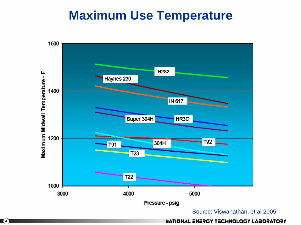
Maximum Use Temperature
Source: Viswanathan, et al 2005
H282

5
Technological Issues
• There is an immediate and continuing need for
increased power production.
• Portfolio diversification dictates the use of coal.
• Increases in Temperature and Pressure increase
efficiency and decrease CO2 production along with
other pollutants.
• Higher Temperature and Pressure place greater
demands upon the Materials.
• Large castings are required for some components—
many technical issues.

6
Example Components
Valve Bodies Turbine Casing
• Castings
– 1-15 tons
– Up to 100mm in thickness
Courtesy Alstom

7
Alloys Under Consideration
Solid Solution Age Hardenable
H230 N105
IN617 N263
IN625 H282
IN740

8
Our Model Casting Geometry
The actual
component is
nominally 4in
thick and
“infinite” in the
other
directions.
Our casting is
nominally 4in in
diameter and 4-
5in tall.

9
“Enhanced” Slow Cooling
Our casting layout is
shown schematically in
cross section on the left.
A permanent graphite
mold was used. This
mold was surrounded by
loose sand such that the
top of the casting was
below the sand line.
This is our attempt to
emulate the “semi-
infinite” plate model of
the turbine casing. Loose Sand
Ingot
Graphite Mold

10
Model Casting Results
Photo taken
moments after
casting. The mold
never showed any
“color” which
meant that the
mold temperature
stayed below
about 550C. This
gave us some
confidence that
slow cooling was
achieved.
Empty melt crucible.
Full mold
(Ingot top is below
loose sand line).
11
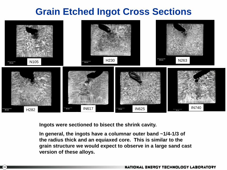
Grain Etched Ingot Cross Sections
Ingots were sectioned to bisect the shrink cavity.
In general, the ingots have a columnar outer band ~1/4-1/3 of
the radius thick and an equiaxed core. This is similar to the
grain structure we would expect to observe in a large sand cast
version of these alloys.
N105 H230 N263
H282 IN617 IN625 IN740

12
First Ingot Chemistries
C Cr Mo Co Al Ti Cb Mn Si B W
Nimonic 105 0.15 14.85 5.00 20.00 4.70 1.10 0.50 0.50 0.05
0.16 14.61 5.02 20.04 4.43 1.10 0.51 0.51 0.05
Haynes 282 0.070 19.50 8.50 10.00 1.50 2.10 0.25 0.15 0.005
0.07 19.22 8.48 9.84 1.44 2.08 0.24 0.15 0.01
IN740 0.030 25.00 0.50 20.00 1.30 1.50 1.50 0.30 0.30 Fe: 0.70
0.04 24.71 0.50 20.03 1.24 1.48 1.50 0.30 0.31 0.57
Nimonic 263 0.070 20.00 5.80 20.00 0.35 2.10 0.50 0.35
0.07 19.68 5.74 19.89 0.40 2.04 0.50 0.34
Haynes 230 0.120 22.00 2.00 0.35 0.70 0.50 14.00
0.12 21.59 2.01 0.37 0.69 0.50 13.91
IN617 0.120 22.00 9.00 12.50 1.10 0.30 0.50 0.50
0.12 21.73 8.96 12.35 1.04 0.31 0.50 0.49
IN625 0.070 21.00 9.00 0.10 0.10 3.60 0.50 0.35
0.07 20.71 8.92 0.15 0.089 3.58 0.49 0.34
Aims
Results

13
Casting the Plate For Welding Studies
Our casting layout is
shown schematically in
cross section on the left.
A permanent graphite
mold was used. This
mold was surrounded by
loose sand such that the
top of the casting was
covered with sand. This
is our attempt to emulate
the “semi-infinite” plate
model of the turbine
casing. Loose Sand
Ingot
Graphite Mold

14
Welded Plates

15
263 Cross Welds

16
H282 Cross Welds

17
Project Tasks • Cast plates from selected alloys for weldability:
– Casting complete
– Evaluation underway
• Work with GE to develop a feature laden prototype
casting to be cast at an outside vendor
– Castings are too large for traditional investment
casting vendors
– Majority of sand casting vendors cast iron and steel
– First vendor identified bowed out
– Second vendor identified and article cast and
homogenized
– Third vendor identified and article cast and
homogenized

18
8” x 8” Volume: 402 in3
7” x 7” x 7” Volume: 343 in3
5” x 5”x 5” Volume: 125 in3
3” x 5” x 5” Volume: 125 in3
2” x 5” x 5” Volume: 125 in3
7” 7” 7”
5” 5”
5”
5”
3”
2”
Blend radius 1”
Blend radius 1”
Blend radius 1”
Blend radius 0.75”
Casting Geometry

19
Segregation Within the FCC Phase
Secondary Dendrite Arm Spacing
~65μm

20
Remnant Segregation After Homogenization
Distance (m)
0.00000 0.00005 0.00010 0.00015 0.00020
We
igh
t P
erc
en
t M
o
0
2
4
6
8
10
12
100um SDAS

21
SDAS—Effect of Position
Patel and Murty, 718 conf. (2000)

22
SDAS—Effect of Cooling Rate
Patel and Murty, 718 conf. (2000)

23
Effect of SDAS on Homogenization
Distance (m)
0.00000 0.00005 0.00010 0.00015 0.00020
We
igh
t P
erc
en
t M
o
0
2
4
6
8
10
12
100um SDAS
Distance (m)
0.00000 0.00005 0.00010 0.00015 0.00020
We
igh
t P
erc
en
t M
o
0
2
4
6
8
10
12
100um SDAS
200um SDAS
Distance (m)
0.00000 0.00005 0.00010 0.00015 0.00020
We
igh
t P
erc
en
t M
o
0
2
4
6
8
10
12
100um SDAS
200um SDAS
400um SDAS

24
SDAS in Larger Casting
Riser Pad SDAS: 154-188µm
Keel Block SDAS: 67-57µm
7”
5”
3”
2”
8”

25
Adjusting of Scale of Microstructure
Distance (m)
0.00000 0.00005 0.00010 0.00015 0.00020
We
igh
t P
erc
en
t M
o
0
2
4
6
8
10
12
100um SDAS
200um SDAS
3h/1100C + 9h/1200C 3h/1100C + 36h/1200C

26
Application to the Casting
Distance (m)
0.00000 0.00005 0.00010 0.00015 0.00020
We
igh
t P
erc
en
t M
o
0
2
4
6
8
10
12
100um SDAS
200um SDAS
MetalTek
3h/1100C + 9h/1200C 3h/1100C + 36h/1200C
3h/1100C + 3h/1200C +12h/1210C

27
Residual Mo Segregation
Minimum (%) Maximum (%)
As-Cast Predicted
Measured 89 127
Long time HT Predicted 94 106
Measured 94 101
HT Applied Predicted 91 109
Measured 92 111

28
Superheat
29
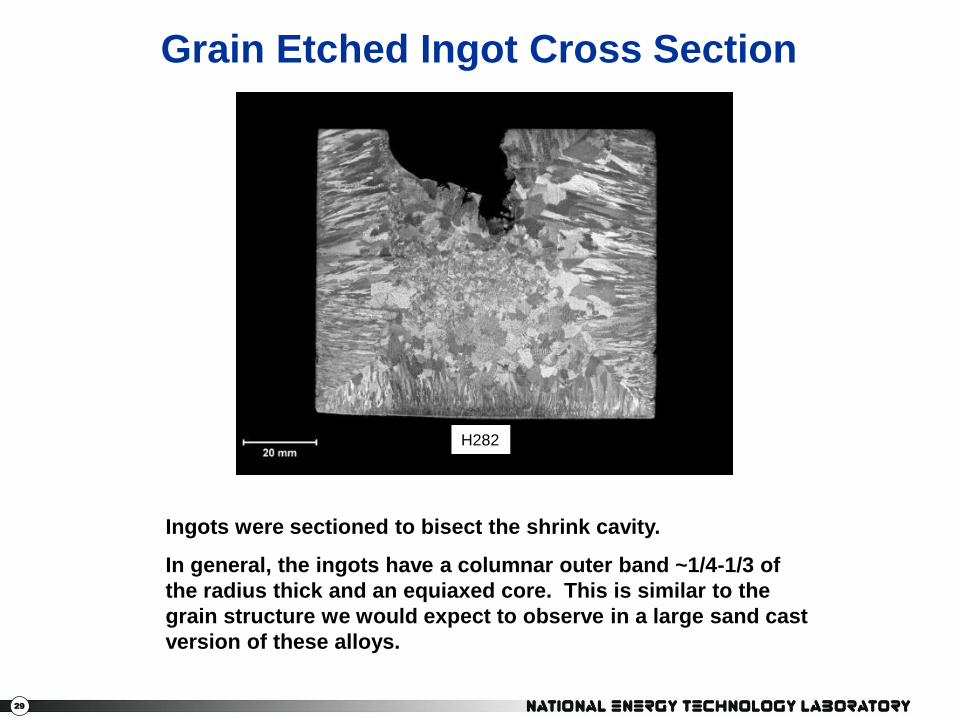
Grain Etched Ingot Cross Section
Ingots were sectioned to bisect the shrink cavity.
In general, the ingots have a columnar outer band ~1/4-1/3 of
the radius thick and an equiaxed core. This is similar to the
grain structure we would expect to observe in a large sand cast
version of these alloys.
H282

30
H282 Secondary Dendrite Arm Spacing
~65μm ~46μm
~92μm ~82μm
Columnar
zone
Equiaxed
zone

31
Superheat
Superheat (C)
40 60 80 100 120 140 160
SD
AS
(m
)
50
55
60
65
70
75
80
85
90
Columnar Region
Equiaxed Region
32
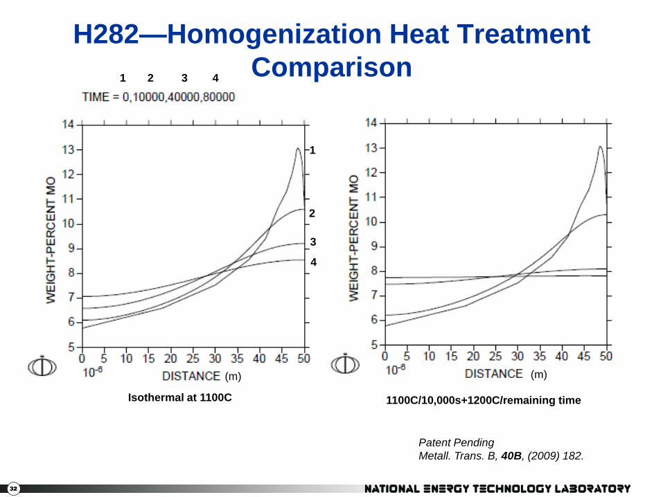
H282—Homogenization Heat Treatment
Comparison
Isothermal at 1100C 1100C/10,000s+1200C/remaining time
1 2 3 4
1
2
3
4
Patent Pending
Metall. Trans. B, 40B, (2009) 182.
(m) (m)

33
As-Cast vs. Homogenized H282
As-Cast Homogenized
Qualitative Confirmation of the Effectiveness of the Homogenization Heat Treatment

34
800C Creep Results
H282
LM = T[K](C[20]+log(t))
20000 21000 22000 23000 24000 25000 26000 27000
Str
ess (
ksi)
10
100 Cast alloy results:
data points
Average wrought
performance: line

35
Section Summary: As-Cast Profiles
• The refractory elements W, Mo, and Nb do not homogenize
after ~22h/1100C
• Significant segregation of the second phase strengthening
elements Al, Ti and Nb were observed in many alloys…to the
point that 1/2-2/3 of the casting would be considered “lean”.
• In some cases, Cr poor regions are predicted.
• Significant Co segregation was observed in some alloys.
• Significant partitioning of Mn and Si to the interdendritic region
was predicted. This result suggests that a turn down in the
levels of these elements may be beneficial (e.g., welding).

36
Tensile Bar Layout
The ingot halves
were cut into
0.4in wide slabs
labeled A, B, etc.
from the left side
of the original
tops. These
were cut into
0.4in wide TB
blanks labeled
A1, A2, etc. from
the ingot center.
A2
A1

37
Alloy 263 Fracture
800C Hot Tensile
Equiaxed Region
Columnar Region

38
263 Yield Strength Results

39
H282 Yield Strength Results

40
263 Ultimate Tensile Results

41
H282 Ultimate Tensile Results
42
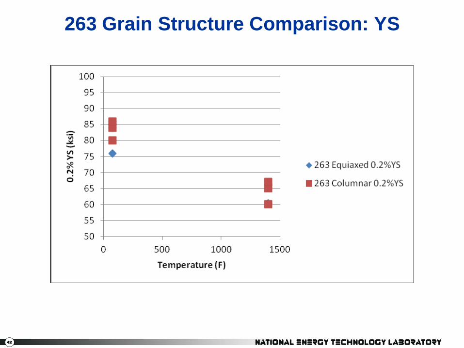
263 Grain Structure Comparison: YS
43
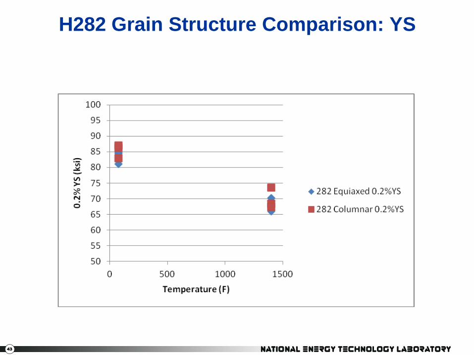
H282 Grain Structure Comparison: YS

44
263 Grain Structure Comparison: UTS

45
H282 Grain Structure Comparison: UTS

46
263 Fatigue at Room Temperature

47
H282 Fatigue at Room Temperature

48
263 Fatigue at 760C

49
H282 Fatigue at 760C

50
Summary
• A-USC conditions will require advanced Ni-based alloys to
operate; alloy 263 and H282 are examined here.
• Small scale castings were made to evaluate the performance of
cast forms of traditionally wrought alloy 263 and H282 with
varying amounts of superheat.
• A computationally optimized homogenization heat treatment
was developed to improve the performance of these alloys.
• The tensile and fatigue performance of these alloys appears to
be little effected by varying superheat.

51
Summary
• In the tensile properties, both alloys showed a 3-5 ksi increase
in UTS for each 50C superheat. In 263, 50C superheat, 0.2% YS
is 5-7 ksi lower than the other two; in H282, 0.2% YS is about
the same across all three.
• In fatigue, H282 showed no discernible effect of superheat
while 263 seems to perform best by a small margin, with a 100C
superheat.
• With respect to grain orientation, columnar vs. equiaxed, the
two alloys show little to no difference across alloys, test
temperatures, and properties.
• The fatigue results compare very favorably to the wrought H282
results gathered in previous work.

52
Disclaimer
"This report was prepared as an account of work sponsored by an agency of the United
States Government. Neither the United States Government nor any agency thereof, nor any
of their employees, makes any warranty, express or implied, or assumes any legal liability
or responsibility for the accuracy, completeness, or usefulness of any information,
apparatus, product, or process disclosed, or represents that its use would not infringe
privately owned rights. Reference herein to any specific commercial product, process, or
service by trade name, trademark, manufacturer, or otherwise does not necessarily
constitute or imply its endorsement, recommendation, or favoring by the United States
Government or any agency thereof. The views and opinions of authors expressed herein
do not necessarily state or reflect those of the United States Government or any agency
thereof."