Embed Size (px)
Citation preview

Address comments to [email protected] comments to [email protected]
Robust FPGA Resynthesis Based on Fault-Tolerant Boolean MatchingRobust FPGA Resynthesis Based on Fault-Tolerant Boolean Matching
Yu Hu1, Zhe Feng1, Lei He1 and Rupak Majumdar2
1Electrical Engineering Dept., UCLA
2Computer Science Dept., UCLAPresented by Yu HuPresented by Yu Hu

OutlineOutline
Background and Motivation
Preliminaries
Robust Resynthesis Algorithms
Experimental Results
Conclusion and Future Work

BackgroundBackground Late CMOS scaling reduces device reliability
Single event upset (SEU) due to cosmic rays
Affects configuration SRAM cells in FPGAs Permanent soft error rate (SER) Need rewriting SRAM for recovery
Affects combinational circuits and FFs Transient SER Can be recovered in multiple clock cycles

Fault Tolerance Techniques for FPGAsFault Tolerance Techniques for FPGAs
Metrics TMR Manufacturer Masking
Chipwise Multi-Config “Ideal”
Defect Coverage
High Low/Medium High Medium High
Area Overhead
High Low None Medium Low
Delay Overhead
High Medium Low Low Low
Testing Cost
Low Medium High Medium Low
Synthesis Cost
Low Medium High Low Low

Fault Tolerance Techniques for FPGAsFault Tolerance Techniques for FPGAs
TMR Manufacturer Masking
Chipwise Multi-Config Stochastic-Synthesis
Defect Coverage
High Low/Medium High Medium Medium
Area Overhead
High Low None Medium None/Low
Delay Overhead
High Medium Low Low Low
Testing Cost
Low Medium High Medium Low
Synthesis Cost
Low Low High Low Low
Our workLow-cost, complementary
approach to existing techniques!
[A. Djupdal and P. Haddow, Yield Enhancing Defect Tolerance Techniques for FPGAs, MAPLD 2006]

Stochastic Synthesis and Logic MaskingStochastic Synthesis and Logic Masking
Stochastic synthesis assumes probabilistic logic values to model effect of random defects Break the conventional Boolean view which assumes
deterministic Boolean ‘0’ and ‘1’ values
Key to stochastic synthesis: Logic Masking
a
c
b
g
Circuit (b)
Masked faults
0
1

Stochastic Synthesis and Logic Masking (cont.)Stochastic Synthesis and Logic Masking (cont.)
Stochastic Synthesis intelligently places logic masking.
Logic Masking reduces the probability of the propagation of random faults Maximizes the stochastic yield
However, logic synthesis to maximize yield rate w/o explicit redundancy and testing has not been studied for fault tolerance!
Key questions How much does logic masking affect robustness? How and where to place logic masking?

How much Logic Masking Affect Robustness?How much Logic Masking Affect Robustness?
18 synthesis solutions obtained by Berkeley ABC
(for MCNC i10, LUT bit fault rate = 0.1%)
Different synthesis leads to different logic masking.
Stochastic synthesis maximizes logic
masking!

How and Where to Place Logic Masking?— Our Major Contributions
How and Where to Place Logic Masking?— Our Major Contributions
Propose a Robust FPGA resynthesis (ROSE) Maximize the stochastic yield rate for FPGAs No need to locate faults Use the same synthesis for different chips of one
FPGA application
Proposed a new PLB template for robustness
ROSE + Robust Template reduces fault rate by 25% with 1% fewer LUTs, and increases MTBF by 31% while preserving the logic depth compared to Berkeley ABC

OutlineOutline
Background
Preliminaries
Robust Resynthesis
Experimental Results
Conclusion and Future Work

FPGA Synthesis FlowFPGA Synthesis Flow
Attempt to re-map a logic block by Boolean matching
Boolean matching can be used to handle both homogenous and heterogeneous PLBs
RTL Synthesis
LogicSynthesis
Technology Mapping Resynthesis Packing P&R

FPGA Synthesis Flow (cont.)FPGA Synthesis Flow (cont.)
Multi-iterations of Boolean Matching-based Resynthesis
(Source: Andrew Ling, University of Toronto, DAC'05)
RTL Synthesis
LogicSynthesis
Technology Mapping Resynthesis Packing P&R

Boolean Matching for ResynthesisBoolean Matching for Resynthesis
2-LUT
2-LUT
2-LUT
2-LUT
2-LUT
ff gg
??
Formulate the sub-problem of resynthesis to Boolean matching (BM) BM: Can function f be implemented in circuit g ? Resynthesis: Is there a configuration to g so that for all
inputs to g, f is equivalent to g?
Existing algorithms: area/delay-optimal(Source: Andrew Ling, University of Toronto, DAC'05)

OutlineOutline
Background
Preliminaries
Robust Resynthesis Problem Formulation FTBM Algorithm Robust PLB Template
Experimental Results
Conclusion and Future Work

Modeling of FaultsModeling of Faults
LB1LB2
Intermediate logics
Fault rateof LB1
Input faults of LB2
CIs
Faults in config-bits
X
Faults in config-bits
X
Model both faults in LUT configurations and the faults in intermediate wires as random variables, whose probabilities are given as inputs of our problem.

Resynthesis(Boolean matching)
ROSE: Robust Resynthesis w/ FTBMROSE: Robust Resynthesis w/ FTBM
Boolean Matching Inputs
PLB H and Boolean function F Fault rates for the inputs and the SRAM bits of the PLB
Outputs Either that F cannot be implemented by PLB H Or the configuration of H which minimizes the probability that
the faults are observable in the output of the PLB under all input vectors.
FTBM tasks breakdown: Step 1: Find a Boolean matching solution Step 2: Evaluation the stochastic fault rate of a solution
RTL Synthesis
LogicSynthesis
Technology Mapping
ROSE(FTBM)
Packing P&R
Fault-Tolerant Boolean Matching

FTBM Step1: SAT Encoding for FTBMFTBM Step1: SAT Encoding for FTBM
LUT1
c0, SRAM
c1, SRAM
c15, SRAM
x'1 x'2 x'3 x'4
LUT2
c16, SRAM
c17, SRAM
c31, SRAM
x'5 x'6 x'7z1
G
x1 x2 x3 x4 x5 x6 x7 F0 0 0 0 0 0 0 F0
1 0 0 0 0 0 0 F1
0 1 0 0 0 0 0
1 1 1 1 1 1 1 F127
F2
PLB
tem
plat
eB
oole
an fu
nctio
n
If implementable, multiple configurations might exist
The one with minimal fault rate is needed!
Conjunctive Normal Form (CNF)

Deterministic SAT vs. SSAT
FTBM Step2: Fault Rate Calculation Based on SSATFTBM Step2: Fault Rate Calculation Based on SSAT
Deterministic SAT Stochastic SAT
Simulation-based fault rate calculation Not scalable for multiple defects
SAT-based fault rate calculation Intelligently modeling random defects

SSAT Encoding for Fault Rate CalculationSSAT Encoding for Fault Rate Calculation
Faults in intermediate wires
Faults in LUT configurations
Binary search is performed to find
the maximal β

Example: SAT-Based FTBMExample: SAT-Based FTBM
abc g
000 1
001 1
010 1
011 0
100 1
101 1
110 0
111 0
g= !x1!x3+ !x2
2-LUT
2-LUT
2-LUT
x1
x2
x3
fz1
z2
Boolean function
PLB Template
Boolean matching

Example: SAT-Based FTBMStep1: CNFs for the PLB template
Example: SAT-Based FTBMStep1: CNFs for the PLB template
2-LUT
2-LUT
2-LUT
x1
x2
x3
fz1
z2
G LUT = ( x1 + x2+ ¬L0 + z) ( x1 + x2+ L0 + ¬ z)
( x1 + ¬ x2+ ¬L1 + z) ( x1 + ¬ x2+ L1 + ¬ z)
(¬ x1 + x2+ ¬L2 + z) (¬ x1 + x2+ L2 + ¬ z)
(¬ x1 + ¬ x2+ ¬L3 + z) (¬ x1 + ¬ x2+ L3 + ¬ z)
L0
L3
L1 4-1 MUX
x1
z
LUT-2
00
11
01
L2 10
x2
PLB Characteristic Function: G = G LUT1 · G LUT2 · G LUT3

Example: SAT-Based FTBMStep2: Replication based on Truth Table
Example: SAT-Based FTBMStep2: Replication based on Truth Table
abc g
000 1
001 1
010 1
011 0
100 1
101 1
110 0
111 0
SAT Instance:
G expand = G[X/000, f/1, z/z0] · G[X/001, f/1, z/z1]
G[X/010, f/1, z/z2] · G[X/011, f/0, z/z3]
G[X/100, f/1, z/z4] · G[X/101, f/1, z/z5]
G[X/110, f/0, z/z6] · G[X/111, f/0, z/z7]
G = G LUT1 · G LUT2 · G LUT3
Replication

Example: SAT-Based FTBMStep3: SAT Solving and Mapping
Example: SAT-Based FTBMStep3: SAT Solving and Mapping
SAT Instance:
G expand = G[X/000, f/1, z/z0] · G[X/001, f/1, z/z1]
G[X/010, f/1, z/z2] · G[X/011, f/0, z/z3]
G[X/100, f/1, z/z4] · G[X/101, f/1, z/z5]
G[X/110, f/0, z/z6] · G[X/111, f/0, z/z7]
SAT!
x1
fx2
x3
2-LUT
2-LUT
2-LUT
x1
x2
x3
fz1
z2
Returned SAT assignments: L1(00) = 0, L1(01)=0, L1(10)=0, L1(11)=1, …

Example: SAT-Based FTBMStep4: Exploring More SAT Solutions
Example: SAT-Based FTBMStep4: Exploring More SAT Solutions
Augmented SAT Instance:
G expand = G[X/000, f/1, z/z0] · G[X/001, f/1, z/z1]
G[X/010, f/1, z/z2] · G[X/011, f/0, z/z3]
G[X/100, f/1, z/z4] · G[X/101, f/1, z/z5]
G[X/110, f/0, z/z6] · G[X/111, f/0, z/z7]
¬ (L1(00) = 0, L1(01)=0, L1(10)=0, L1(11)=1, …)/* Complement of previous SAT assignments */
2-LUT
2-LUT
2-LUT
x1
x2
x3
fz1
z2
x1
fx2
x3
New Configuration
x1
fx2
x3
Previous Configuration
Fault rate = 0.2Fault rate = 0.2Fault rate = 0.3Fault rate = 0.3

PLB Templates for SAT-based ResynthesisPLB Templates for SAT-based Resynthesis
4LUT
4LUT
4LUT
X1
X2
X3
X4
X5
X6
X7X8
X9
X10G
4LUT
4LUT
X1
X2
X3
X4
X5
X6
X7
G
F
F1
F2
4LUT
4LUT
4LUT
X1
X2
X3
X4
X5
X6
X7
X8
X9
X10 G
F1
F2
Area efficient templates [A. Ling, DAC’05]
Proposed robust template w/ path-reconvergence Can be configured by existing FPGAs
4-LUT
4-LUT
4-LUT4-LUT
X1
X2
X3
X4
X5
X6
X7
X8
X9
X10
X11
X12
z1
z3
z2
G
F1
F2

Templates for SAT-based Resynthesis (cont.)Templates for SAT-based Resynthesis (cont.)
LUT4
LUT4
LUT4 LUT4
X1
X2
X3
X4
X5
X6
X7
X8
X9
X10
X11
X12
z1
z3
z2
G
F1
F2
Robust PLB template introduces more potential of don’t-cares
ROSE maximizes don’t-cares iteratively at each template output
LUT2
LUT2
00 101 110 x11 1
z1
z3
z2
X1
X2
X3
X4
LUT2
00 x01 x10 x11 x
LUT2z1
z3
z2
X1
X2
1
1
G
(a) (b)
Satisfiability don’t-
care
Observability don’t-
care

OutlineOutline
Background
Preliminaries
Robust Resynthesis
Experimental Results
Conclusion and Future Work

Experimental SettingsExperimental Settings
Implementation in OAGear SAT-BM uses miniSAT2.0
QUIP benchmarks are tested Are first mapped with 4-LUTs by Berkeley ABC
Resynthesis settings One traversal is performed Blocks with up to 10 inputs are considered
The fault rate of the chip is calculated by Monte Carlo simulation with 20K random vectors assuming the single fault
Results are verified by ABC equivalency checkers
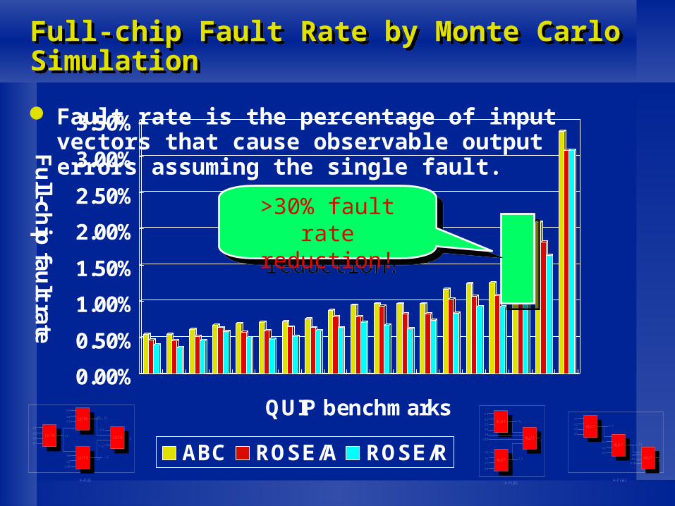
Full-chip Fault Rate by Monte Carlo SimulationFull-chip Fault Rate by Monte Carlo Simulation
0.00%
0.50%
1.00%
1.50%
2.00%
2.50%
3.00%
3.50%
Fu
ll-chip
fault rate
QUIP benchmarks
ABC ROSE/A ROSE/R
>30% fault rate reduction!
>30% fault rate reduction!
Fault rate is the percentage of input vectors that cause observable output errors assuming the single fault.
4LUT
4LUT
4LUT
X1
X2
X3
X4
X5
X6
X7X8
X9
X10G
F1
F2
4LUT
4LUT
4LUT
X1
X2
X3
X4
X5
X6
X7
X8
X9
X10 G
F1
F2
A-PLB1A-PLB2
LUT4
LUT4
LUT4 LUT4
X1
X2
X3
X4
X5
X6
X7
X8
X9
X10
X11
X12
z1
z3
z2
G
F1
F2
R-PLB

Area (LUT#) Area (LUT#)
0
500
1000
1500
2000
2500
3000
3500
LU
T#
QUIP benchmarks
ABC ROSE/A ROSE/R
ABC vs. ROSE/A vs. ROSE/R:1: 0.9 : 0.99
ABC vs. ROSE/A vs. ROSE/R:1: 0.9 : 0.99
4LUT
4LUT
4LUT
X1
X2
X3
X4
X5
X6
X7X8
X9
X10G
F1
F2
4LUT
4LUT
4LUT
X1
X2
X3
X4
X5
X6
X7
X8
X9
X10 G
F1
F2
A-PLB1A-PLB2
LUT4
LUT4
LUT4 LUT4
X1
X2
X3
X4
X5
X6
X7
X8
X9
X10
X11
X12
z1
z3
z2
G
F1
F2
R-PLB

Estimation of Mean Time Between FailureEstimation of Mean Time Between Failure
SER modeling: [Mukherjee, HPCA, 2005]
Assume max-size FPGA: 330,000 LUTs
20.66
27.15
0 5 10 15 20 25 30
MT
BF
(ye
ar)
ABC ROSE/R 31% MTBF increase!

OutlineOutline
Background
Preliminaries
Robust Resynthesis
Experimental Results
Conclusion and Future Work

Conclusions and Future WorkConclusions and Future Work
Developed ROSE and a robust template. ROSE is an orthogonal approach compared to existing
fault-tolerant technique. Virtually no overhead on power, delay and area
In the future, we will consider Multiple correlated faults, Alternative algorithms, Extension to standard cell-based circuits, Impacts on testability.

Robust FPGA Resynthesis Based on Fault-Tolerant Boolean Matching
Yu Hu, Zhe Feng, Rupak Majumdar and Lei He
University of California, Los Angeles