Embed Size (px)
Citation preview

E1E2
D
C
18" (457 mm) 20 ¹¹⁄₁₆" (525 mm) 9 ¼" (235 mm) 10 ⁄₁₆" (265 mm)24" (610 mm) 26 ⅝" (677 mm) 11 ¾" (299 mm) 13" (330 mm)30" (762 mm) 32 ¹¹⁄₁₆" (830 mm) 14 ⁵⁄₁₆" (363 mm) 15 ⁹⁄₁₆" (395 mm)36" (914 mm) 38 ⁹⁄₁₆" (980 mm) 16 ⅞" (428 mm) 18 ⅛" (460 mm)
¾" (19 mm).
Additional planning notes for Vario 400 series cooling
The side walls of the adjacent cabinetry have to be dimensionally stable, as the Vario cooling appliances are secured in the cutout with only an anti-tilt bracket on the top back and on the bottom at the side.
Vario cooling appliances can be installed handle to handle as a side-by-side com-bination. In this case the side-by-side installation kit RA 460 000 is required. If the distance between the appliances is greater than ⅝" (16 mm) or less than 6 ⁵⁄₁₆" (160 mm) or the environment very humid the additional side heating element RA 460 012 needs to be installed between the appliances to avoid condensation.
If the appliances are combined hinge to handle in a very humid environment the additional side heating element RA 460 012 is required as well. It can be omitted if the distance between the appliances is greater than 6 ⁵⁄₁₆" (160 mm) The additional side heating element RA 460 012 does not take up any additional space. It is already included in the cutout dimensions.
If the Vario cooling appliances are joined together hinge to hinge an additional stable side wall must be added.
If restrictions in use are accepted (no simultaneous opening of the doors possible) the appliances can be joined together directly, using the additional side heating element RA 460 012.
When installing a 400 series Vario cooling appliance next to a 400 seriesBO/BM/BS/CM appliance, a minimum lateral distance of 1 ³⁄₁₆" (30 mm) is required.
When installing a cooling appliance next to a BOP/BMP from the 200 series ovens, a minimum lateral distance of 1 ³⁄₁₆" (30 mm) is required, if the non-hinge side of the cooling appliance is next to the BOP/BMP. If both appliances are hinged on the same side, a minimum lateral distance of 1 ⁹⁄₁₆" (40 mm) is required.
Door opening angle
To ensure correct kitchen planning it is essential to take into account the opening angle of the appliance door (plus fitted cabinet door and handle). There should be no possibility of collision with other kitchen furnishings (countertops, handles of other cabinetry etc.) or parts of the room (walls, protrusions etc.).The space needed for the hinge and the consequential distance to the adjacent cabinetry and its handle can, depending on the panel thickness, be seen in the following drawing. The drawing assumes a panel thickness of ¾" (19 mm).If a collision occurs, the following options are available to remedy the situation:Restrict the door opening angle to 90° (standard 115°). Pin to restrict the angle is enclosed with the appliance. Due to limitation in use, it is not recommended to install a freezer (RF 411, RF 461, RF 463, RF 471, RF 491) next to a wall which requires a door angle of 90° or any other installation which requires a 90° door angle as draw-ers can’t be pulled out completely or removed.. If the restrictions in use are accepted, the ice storage container must be exchanged for the small ice storage container (RA 448 220). This must be done prior fixing the door. Fit a spacer between the appliance and the cabinetry that it would collide with. Rearrange surrounding cabinetry or appliance
Notes:
– The adjustable feet have an adjustment range of +1 ⅜"(+35 mm) to -½-(13 mm). The standard height displayed in the pictures is 0 mm.
– For proper ventilation of the appliance, the clear ance between the floor and bottom edge of the cabinet front must be at least 3 ¹⁵⁄₁₆"(100 mm).
– The panel thickness of customized doors can range from between ¾" (19 mm) and 1 ½" (38 mm) (in the picture ¾" (19 mm)).
Wall clearance RB 492/RY 492
Wall clearance RB 472/RC/RF/RW
www.gaggenau.com/usRevised: June 2021

Location
The appliance should be installed in a dry, well ventilated room. The location of the appliance should not be subject to direct sunlight or near a source of heat, such as an oven, a radiator, etc. If installation next to a heat source is unavoidable, observe the following minimum dis tances from the heat source:
– 1 ³⁄₁₆" (3 cm) to electric or gas. When installing next to a cooktop, always refer to the cooktop installation instructions for more information.
– 11 ¹³⁄₁₆" (30 cm) from an oil or solid fuel cooktop.The floor of the installation location must not give way; if required, reinforce floor. To ensure that the ice maker functions correctly, the appliance must be upright.
Surface
To ensure that the appliance is installed securely and functions properly, the surface must be level and even. The floor must consist of a hard, rigid material. The floor in the installation area must have the same height as the floor in the rest of the room. Due to the heavy weight of a fully loaded appliance, the floor beneath must be stable. If in doubt, consult an architect, structural engineer or construction expert.
Refer to the following table for load-bearing capacity:
Model Description Maximum load weight
RC462 24" refrigeration column 983 lbs (446kg)
RC472 30" refrigeration column 1,148 lbs (521kg)
RC492 36" refrigeration column 1,430 lbs (649kg)
RF411 18" freezer column 806 lbs ( 366kg)
RF461 24" freezer column 902 lbs (450kg)*
RF471 30" freezer column 1,177 lbs (533kg)
RF491 36" freezer column 1,403 lbs (636kg)
RF463 24" ice & water dispenser columns 1,068 lbs (484kg)
RB472 30" two-door bottom freezer 1,222 lbs (554kg)
RB492 36" two-door bottom freezer 1,444 lbs (655kg)
RY492 36" three-door bottom freezer 1,682 lbs (763kg)
RW414 18" wine climate cabinet 867 lbs (394)kg
RW466 24" wine climate cabinet 1,093 lbs (496kg)
*without water dispenser
Neighboring cabinetry
The new appliance is screwed firmly in place with the neighboring cabinet parts. Care should be taken to ensure that all cupboards onto which something is fastened, are connected firmly to the floor or the wall. The thickness of the toe kick can be a maximum ¾" (19 mm).
Unlike conventional built-in appliances, cooling appliances stand on the floor. This means that the installation cutout is a space in a line of kitchen units.
Installation cutout
The specified dimensions of the installation cutout must be observed to guarantee the proper installa tion of the appliance and the design of the cabinet front. It is particularly important that the installation cutout is square. The side walls must be smooth, not have any protrusions or unevenness. Use the appropriate tools, e.g. spirit level, diagonal measurements, etc. to determine whether the installation cutout is square. The side walls and the upper molding of the installation cutout must be at least ⅝" (16 mm) thick.
A Area for installation the water connectionB Area for installation the electrical connection must be outside the cutoutC Depth of installation cutout, depending on kitchen design.
C = 24" (610 mm) minimum!X Width of installation cutout, refer to the table below for more details:
Appliance type Width of the cutout X
17 ¾" (451 mm) 18" (457 mm)
23 ¾" (603 mm) 24" (610 mm)
29 ¾" (756 mm) 30" (762 mm)
35 ¾" (908 mm) 36" (914 mm)
Installation cutout for a side-by-side solution:
In a side-by-side solution, there are many ways to combine the appliances.The width of the installation cutout is calculated from the sum of the widths of the individual appliances. The height and depth of the installation cutout cor respond to the specifications for the individual ap pliances. It is important to comply with the dimensions in the area set aside for electric and water connections. For the precise dimensions, please refer to the de tails given for individual appliances.
84"(2134)
8311/16"(2126)
3 (100)15/16"
1" (25)
3/8" (10)
Installation cutout for an individual appliance:
Installation cutout
www.gaggenau.com/usRevised: June 2021
www.gaggenau.com/usRevised: June 2021

Water Location
A cold water connection is required for appliances that feature an ice maker or an ice and water dispenser.
The water pressure must be between 40 and 120 p.s.i. (2.75-8.25 bar). The installation must comply with local plumbing regulations.
A separate shut-off valve must be installed for the appliance water connection.
The shut-off valve for the water connection may not be behind the appliance. It is recommended to place the shut-off valve outside the cutout next to the appliance or in another easily accessible location. When installing the water connection, observe the permitted installation areas for the water supply line. The supply line can be located to the right (a), to the left (b), or underneath (c).
Planning Information
www.gaggenau.com/usRevised: June 2021

Recommended Installations Considerations
Stand-Alone Any appliance can be installed as a stand-alone unit. Ensure a cutout flush to the appliance at a depth of minimum 4" (102 mm), preferably 6" (152 mm) on the top and sides.
Side-By-Side When two appliances are installed side-by-side a sealing kit must be used. For combinations that involve a freezer column, this kit is provided. For all other (non-traditional) side-by-side combinations or instances where any appliances are installed less than 6" (152 mm) apart from one another but not connected side-by-side, purchase the Heater Kit (RA 460 012).
Split Columns with Partition
When dimensioning the partition, note the thickness of the door panel (including handles) as well as the swivel range to prevent damage if the doors are opened at the same time.
Three appliances can be installed together only if a partition—minimum 5/8" (16 mm)—is placed between two of the appliances. Ensure that door panel thickness (including handles) as well as the swivel range are accounted for.
At The End of a Cabinetry Run
All Gaggenau cooling appliances must be completely enclosed on the top and sides. If one side of the appliance is visible, a decorative side panel must be used. The side panel must be connected firmly to the wall, the floor and any overhead cabinet / fixtures before the appliance is placed in the cutout.
Recommended Installations Concerns
It is absolutely essential to ensure that the appliance is installed in such a way that the doors do not interfere with an adjacent wall or other kitchen elements.
A partition—minimum 5/8" (16 mm)—is required to ensure the doors do not interfere with one another when opened. Use a partition to separate appliances and observe the door opening range.
*The Gaggenau warranty shall apply only to recommended installations.
The modular refrigerator and freezer column concept from Gaggenau offers you a variety of installation possibilities. In some instances, optional accessories are required!
Installation options
www.gaggenau.com/usRevised: June 2021
www.gaggenau.com/usRevised: June 2021

Toe kick area | Upper molding of cutout (niche)
Upper molding
The height of the cabinet door on the appliance is dependent on: – the overall height of the appliance, – the distance from the bottom edge of the cabinet door to the floor, – the appliance type (one-door or multi-door appliances).
The overall height of the appliance is 79 ⅞" (2,029 mm).
The height can be adjusted within a range of -½" (-13 mm) to +1 ⅜" (+35 mm). You must observe the minimum distance of 3 ¹⁵⁄₁₆" (100 mm) between the upper edge of the floor and the bot tom edge of the cabinet door of the appliance.
This height can vary depending on the conditions at the site. It is possible, e.g. for design reasons, to lengthen the cabinet door upwards by extending it beyond the top of the appliance.
4"(102)
⅛"(3)
⅛"(3)
84"*(2136)
79 ⅞"(2029)
Possible extension of the door panel
Upper molding
Appliance
Appliancedoor
Standard door panel
* Adjustment in leveling legs: -½" (-13 mm) to 1 ⅜" (35 mm)
Important!It must be ensured that the upper molding of the instal lation cutout always has a depth of at least 3 ¹⁵⁄₁₆" (100 mm) (measured from the front edge of the appliance). Only then can the secure installation of the appliance in the installation cutout be guaranteed.
Toe kick and venting grill
Important!Poor ventilation leads to damage to the appliance! Under no circumstances is it permitted to cover the air inlets and the exhaust air outlets of the appli ance in the lower toe kick area. You must observe the minimum distance of 3 ¹⁵⁄₁₆" (100 mm) between the upper edge of the floor and the bot tom edge of the cabinet door of the appliance. Take this into consideration also when adjusting the appliance feet.
In relation to the standard height, the maximum height of the base board is 4" (102 mm). The toe kick can be maximum ¾" (19 mm) thick.
Adhesive connectors are supplied on the front panel of the appliance for fitting the base board.
The air inlets and the exhaust air outlets of the appliance are located above the base board. They must not be covered.
For design reasons, it may be necessary to in crease the distance between the upper edge of the floor and the bottom edge of the cabinet door of the appliance, so that it extends beyond the stan dard dimension of 4" (102 mm). The maximum dimen sion is 7 ⅛" (181 mm). If this is the case, air inlets and exhaust air outlets would become visi ble!
In relation to the standard height of the appliance, the height of the toe kick plate is 4" (102 mm). Maximum thickness of the toe kick plate is ¾" (19 mm).
Base details
max. ¾" (19)
¾"
"(181) 4"
(102)
2 ⅞"–3 ¹⁵⁄₁₆"(73-100)
www.gaggenau.com/usRevised: June 2021

The cabinetry, the height of the toe-kick, the overall height of the kitchen and other determining dimensions of the kitchen must be taken into ac count, in order to plan the exact positioning of the cabinet door so that the appliance integrates per fectly into the overall picture of the kitchen.
The following diagrams show the basic dimensions of the optional accessories door fronts/door front frames for various appliances.
The dimensions of the doors shown are designed for the following basic specifications:
– Height of the toe-kick: 4" (102 mm) – Overall height of the installation cut-out: 84" (2134 mm) – Gap: ⅛" (3 mm) – Panel thickness: ¾" (19 mm)
These specifications provide you with a good starting point for a variety of kitchen designs.
When designing a customized cabinet door, please ensure that the back of the cabinet door is visible to a height of 8 ¹⁄₁₆" (205 mm) over the floor when opening the appliance door and adapt to the front design. All diagrams are also valid for doors without handle.
Important!While these diagrams can serve as a general guide in planning panel dimensions, the correct panel dimensions are dictated by design choices including style and dimensions of surrounding kitchen cabinetry, case and toe kick height, etc. Please ensure careful planning based on the specific kitchen design.
Maximum permitted door panel weight (for each door front)
Model Description Max. panel weight
RC462 24" refrigerator column 90 lbs (41kg)
RC472 30" refrigerator column 53 lbs (24kg)
RC492 36" refrigerator column 95 lbs (43kg)
RF411 18" freezer column 130 lbs (59 kg)
RF461 24" freezer column 90 lbs (41kg)
RF471 30" freezer column 55 lbs (25 kg)
RF491 36" freezer column 95 lbs (43kg)
RF463 24" ice & water dispenser columns 147 lbs (67kg)
RB472 30" two-door bottom freezer 90 lbs. (41kg) Drawer 22 lbs (10kg)
RB492 36" two-door bottom freezer 103 lbs. (47kg)Drawer 22 lbs. (10kg)
RY492 36" three-door bottom freezer 147 lbs. (67kg)Drawer 22 lbs. (10kg)
RW414 18" wine climate cabinet 167 lbs (76 kg)
RW466 24" wine climate cabinet 160 lbs (73 kg)NOTE #1: The cutout for the dispenser unit must be horizontally and vertically centered in the panel.NOTE #2: For custom wine preservation column door panels, the width of the two lateral flanges of
the frame may vary between 2 1/2" (64 mm) and 3 ¾" (95 mm).
Dimensions of the optional accessories – door panels | door panel frames
2(55)3/16"
2113/16"(554)
2113/16"(554)
233/4" (603)
797/8"(2029)
2(55)3/16" 2
(75)15/16"
797 /8
"(20
29)21
13/1
6"(5
54)
2113
/16"
(554
)
233/4" (603)
57 /8
"(1
49)
101 /8
"(2
57)
233/4" (603)
9(230.5)
1/16"
2(55)3/16"
141/2"(368)
797/8"(2029)
2113/16"(554)
2113/16"(554)
233/4" (603)
Recess width 24" (61cm)Recess width 24" (61cm)
The door panel thickness is ¾" (19mm).The maximum door panel dimension are based on a clearance of ⅛" (3 mm), based on a singe recess.A: The cut-out for the ice and water dispenser is designed so that it is horizontally and vertically centered.B: Width of the side frame parts of the door panel can be between 2 ⁹⁄₁₆" (65 mm) and ¼" (82mm).
The door panel thickness is ¾" (19mm).The maximum door panel dimension are based on a clearance of ⅛" (3 mm), based on a singe recess.B: Width of the side frame parts of the door panel can be between 2 ⁹⁄₁₆" (65 mm) and ¼" (82mm).
2(55)3/16" 2
(75)15/16"
57 /8
"(1
49)
2113
/13"
(554
)21
13/1
3"(5
54)
101 /8
"(2
57)
797 /8
"(20
29)
17 3/4" (451)
2(55)3/16"
797 /8
"(20
29)
2113
/13"
(554
)21
13/1
3"(5
54)
17 3/4" (451)
2(55)3/16"
2113
/16"
(554
)21
13/1
6"(5
54)
797 /8
"(20
29)
35 3/4" (908)
The door panel thickness is ¾" (19mm).The maximum door panel dimension are based on a clearance of ⅛" (3 mm), based on a singe recess.
2(55)3/16"
2113
/16"
(554
)21
13/1
6"(5
54)
797 /8
"(20
29)
293/4" (756)
Recess width 30" (76.2cm)
The door panel thickness is ¾" (19mm).The maximum door panel dimension are based on a clearance of ⅛" (3 mm), based on a singe recess.
2(55)3/16"
2113
/16"
(554
)21
13/1
6"(5
54)
2(55)3/16"
293/4" (756)
25(637)
1/16"
287 /16
"(72
2)51
5 /16"(
1304
)
2 (55)3/16"
287 /16
"(72
2)
31(787)
"
35 3/4" (908)
2113
/16"
(554
)21
13/1
6"(5
54)
2113
/16"
(554
)21
13/1
6"(5
54)
515 /16
"(13
04)
2(55)3/16"
17(452)
13/16" 17(452)
13/16"2(55)3/16"
2113
/16"
(554
)21
13/1
6"(5
54)
2(55)3/16"
287 /16
"(72
2)51
5 /16"(
1304
)
31(787)
"
35 3/4" (908)
Recess width 18" (45.7cm)
Recess width 36" (91.4cm)
www.gaggenau.com/usRevised: June 2021
www.gaggenau.com/usRevised: June 2021
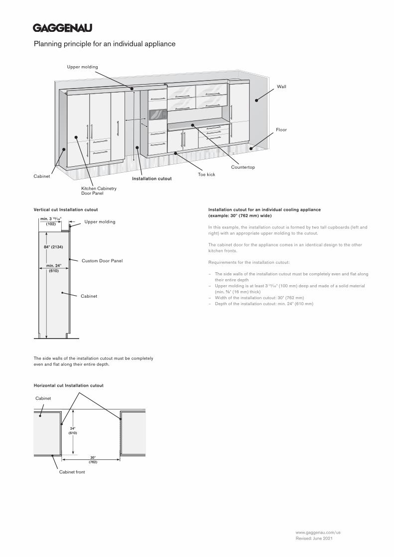
Planning principle for an individual appliance
Installation cutout for an individual cooling appliance (example: 30" (762 mm) wide)
In this example, the installation cutout is formed by two tall cupboards (left and right) with an appropriate upper molding to the cutout.
The cabinet door for the appliance comes in an identical design to the other kitchen fronts.
Requirements for the installation cutout:
– The side walls of the installation cutout must be completely even and flat along their entire depth
– Upper molding is at least 3 ¹⁵⁄₁₆" (100 mm) deep and made of a solid material (min. ⅝" (16 mm) thick)
– Width of the installation cutout: 30" (762 mm) – Depth of the installation cutout: min. 24" (610 mm)
Kitchen Cabinetry Door Panel
Cabinet
Upper molding
Installation cutoutToe kick
Wall
Countertop
Floor
min. 24"(610)
84" (2134)
min. 3 ¹⁵∕₁₆"(102) Upper molding
Custom Door Panel
Cabinet
24"(610)
30"(762)
Cabinet
Cabinet front
Horizontal cut Installation cutout
The side walls of the installation cutout must be completely even and flat along their entire depth.
Vertical cut Installation cutout
www.gaggenau.com/usRevised: June 2021

Planning principle for a side-by-side solution
min. 24"(610)
84" (2134)
min. 3 ¹⁵∕₁₆"(102) Upper molding
Custom Door Panel
Cabinet
Horizontal cut Installation cutout
The side walls of the installation cutout must be completely even and flat along their entire depth.
Vertical cut Installation cutout Installation cutout for a side-by-side solution
– 24" (610 mm) cooling appliance (right) – 18" (457 mm) freezer (left)
In this example, the installation cutout is formed by a tall cupboard (left) and a stable toe kick (right) together with an appropriate upper molding for the cutout.
The cabinet door for both appliances comes in an identical design to the other kitchen fronts.
Requirements for the installation cutout:
– The side walls of the installation cutout must be completely even and flat along their entire depth
– Upper molding is at least 3 ¹⁵⁄₁₆" (100 mm) deep and made of a solid material (min. ⅝" (16 mm) thick)
– Width of the installation cutout: 24" (610 mm) + 18" (457 mm) = 42" (1,067 mm)
– Depth of the installation cutout: min. 24" (610 mm)
Upper molding
Installation cutout Toe kick
Wall
Countertop
Floor
Stable filler
Kitchen Cabinetry Door Panel
Cabinet
min. 24"(610)
24"(610)
18"(457) 42"
(1067) Countertop
Wall cabinet
Stable filler
Cabinet front
www.gaggenau.com/usRevised: June 2021
www.gaggenau.com/usRevised: June 2021

Planning examples
Side-by-side solution 1
RF 471 / RC 492Usability limitations: No limitation.Installation accessories: 1x RA 460 000 installa tion accessories for side-by-side installation (SxS)*.Notes: Door hinges on the outside.
Side-by-side solution 2
RW 414 / RB 472Usability limitations: No limitation.Installation accessories: 1x RA 460 000 installa tion accessories for side-by-side installation (SxS)*.Notes: Door hinges on the outside. Change door hinge of RW.If using the stainless steel fronts with a handle (installation accessories), select the correct door hinges for the RW.
Side-by-side solution 3
RW 414 / RY 492Usability limitations: Not all doors can be opened at the same time. The left door of the RY may col lide with the handle of the RW.Installation accessories: 1x RA 460 000 installation accessories for side-by-side installation (SxS)*.Notes: Fitting the left RY doors at 90° is recommended. Change door hinge of RW. If using the stainless steel fronts with a handle (installation accessories), select the correct door hinges for the RW.
Combination of 3
RF 461 / RW 466 / RC 462Usability limitations: The doors of RW and RC cannot be opened at the same time, but one after another.Installation accessories: 2x RA 460 000 installation accessories for side-by-side installation (SxS)*.Notes: All three appliances must be connected to each other before installation and pushed together into the installation cutout.
Maximum distance
RF 471 / RF 463 / RW 466 / RC 472Usability limitations: No limitation. All doors can be opened fully.Installation accessories: 2x RA 460 000 (SxS)*.Notes: Two separate installation cutouts. Clearance is large enough to open all doors at the same time. Change door hinge of RW 466. If using the stainless steel fronts with a handle (installation accessories), select the correct door hinges for the RW.
SxS
SxS
SxS
SxS SxS
SxS SxSwww.gaggenau.com/usRevised: June 2021

Footnote:*SxS Accessory for side-by-side installation. In an very humid environment always use the additional
side heating element instead of the accessory for side-by-side installation.*HE Additional side heating element. Always required, if the distance between the appliances is
greater than ⅚" (16 mm) or less than 6 ⁵⁄₁₆" (160 mm).
Distance ≥ 6 ⁵⁄₁₆" (160 mm)
RF 471 / RF 463 / RW 466 / RC 472Usability limitations: The middle doors cannot be opened at the same time.Installation accessories: 2x RA 460 000 (SxS)*.Notes: Two separate installation cutouts. The clear ance between the two installation cutouts is greater than 6 ⁵⁄₁₆" (160 mm). Change door hinge of RW. If using the stainless steel fronts with a handle (installation accessories), select the correct door hinges for the RW.
Distance ≤ 6 ⁵⁄₁₆" (160 mm)
RF 471 / RF 463 / RW 466 / RC 472Usability limitations: It may be necessary to open the middle doors one after the other, rather than at the same time. Installation accessories: 2x RA 460 000 (SxS)*, 1x RA 460 012 (HE)*.Notes: Two separate installation cutouts with a stable filler between them. The clearance between the two installation cutouts is less than 6 ⁵⁄₁₆" (160 mm). Therefore, an additional side heating element is required. Change door hinge of RW. If using the stainless steel fronts with handle (installation accessories), select the correct door hinges for the RW.
Combination of 4
RF 471 / RF 463 / RW 466 / RC 472Usability limitations: The middle doors cannot be opened at the same time.Installation accessories: 3x RA 460 000 installation accessories for side-by-side installation (SxS)*.Notes: All four appliances must be connected to each other before installation and pushed together into the installation cutout. Change door hinge of RF 471 and RW 466. If using the stainless steel fronts with handle (installation accessories), select the correct door hinges for the RW.
Combination of 4 - alternative
RF 471 / RF 463 / RW 466 / RC 472Usability limitations: If the middle door is open, then neither of the outer doors can be opened.Installation accessories: 3x RA 460 000 installation accessories for side-by-side installation (SxS)*.Notes: The appliances in the middle are connected side-by-side. Connecting the others will require ad ditional side heating elements. All four appliances must be connected to each other before installation and pushed together into the installation cutout.
SxS SxS
SxS SxSHE
SxS SxSSxS
SxS SxSSxS
www.gaggenau.com/usRevised: June 2021
www.gaggenau.com/usRevised: June 2021