Embed Size (px)
Citation preview

CDH-13072 Addendum No. 4
04 4350-1
SECTION 04 4350 CAST STONE
PART 1 GENERAL 1.01 SUMMARY A. Furnish labor, equipment, materials and services to provide cast stone masonry as specified
in this Section in locations shown or scheduled on Drawings. B. The manufacturer shall be responsible for all labor, materials, equipment and services
necessary for and incidental to providing all cast stone covered by this specification. 1.02 REFERENCES A. American Society for Testing and Materials:
1. ASTM A82-01 – Standard Specification for Steel Wire, Plain, for Concrete Reinforcement. 2. ASTM A184-01 – Standard Specification for Fabricated Deformed Steel Bar Mats for
Concrete Reinforcement. 3. ASTM A185-01 – Standard Specification for Steel Welded Wire Reinforcement, Plain, for
Concrete. 4. ASTM A497-01 – Standard Specification for Steel Welded Wire Reinforcement, Deformed,
for Concrete. 5. ASTM A615-01 – Standard Specification for Deformed and Plain Billet-Steel Bars for
Concrete Reinforcement. 6. ASTM C31-00 – Standard Practice for Making and Curing Concrete Test Specimens in the
Field. 7. ASTM C33-02 – Standard Specification for Concrete Aggregates. 8. ASTM C39-01 – Standard Test Method for Compressive Strength of Cylindrical Concrete
Specimens. 9. ASTM C97-96 – Standard Test Methods for Absorption and Bulk Specific Gravity of
Dimension Stone. 10. ASTM C150-02 – Standard Specification for Portland Cement. 11. ASTM C260-01 – Standard Specification for Air-Entraining Admixtures for Concrete. 12. ASTM C494-99 – Standard Specification for Chemical Admixtures for Concrete. 13. ASTM C642-97 – Standard Test Method for Density, Absorption, and Voids in Hardened
Concrete. 14. ASTM C979-99 – Standard Specification for Pigments for Integrally Colored Concrete. 15. ASTM C1194-03 – Standard Test Method for Compressive Strength of Architectural Cast
Stone. 16. ASTM C1195-03 – Standard Test Method for Absorption of Architectural Cast Stone. 17. ASTM C1364-97 – Standard Specification for Architectural Cast Stone.
1.03 SUBMITTALS A. Submit a sample of stone representative of profiles, color and texture of stone to be installed. B. Submit shop drawings showing size, dimensions, sections and profiles of stonework units,
arrangement and provisions for jointing, anchoring and fastening, supports and other necessary details for lifting devices and reception of other work. Indicate location of each stonework unit on setting drawings with number designation corresponding to number marked on each unit. Show location of inserts (for stone anchors and supports) which are to be built into concrete or masonry.
1.04 QUALITY CRITERIA A. Design, construction, casting, and installation shall be in accordance with the Cast Stone
Institute Technical Manual and in compliance with ASTM C1364. B. Obtain stone from manufacturer with consistent color range and texture throughout work. C. The manufacturer shall have a minimum of five (5) years continuous operation, having
experience, adequate facilities and capacity to furnish the quality, sizes and quantity of cast stone required without delaying the work. Manufacturers should be ready to illustrate examples having been exposed to weather.
1.05 PRODUCT DELIVERY, STORAGE AND HANDLING A. Protect stone during storage and construction against moisture, soiling, staining and physical
damage. B. Handle stone to prevent chipping, breakage, soiling or other damage. Do not use pinch or
wrecking bars without protecting edges of stone with wood or other rigid materials. Lift with wide-belt type slings wherever possible; do not use wire rope or ropes containing tar or other substances which might cause staining. If required, use wood rollers and provide cushion at end of wood slides. Contractor shall replace any damaged stonework at no cost to the Owner.
CDH-13072 Addendum No. 4
04 4350-2
C. Store stone on wood skids or pallets, covered with non-staining, waterproof membrane. Place and stack skids and stones to distribute weight evenly and to prevent breakage or cracking of stones. Protect stored stone from weather with waterproof, non-staining covers or enclosures, but allow air to circulate around stones.
D. Protect mortar materials and stonework accessories from weather, moisture and contamination with earth and other foreign materials.
1.06 JOB CONDITIONS A. Environment Requirements:
1. Lay no stonework where temperature of surrounding air has dropped below 45 degrees F., unless it is rising; and at no time when it has dropped below 40 degrees F., except by written permission from Architect.
2. When stonework is authorized during temperature below 40 degrees F., but above freezing, heat sand and/or water to produce mortar temperature between 40 degrees F. and 120 degrees F.
PART 2 PRODUCTS 2.01 MATERIALS A. Cement - Portland Type I or Type III white meeting ASTM C150. B. Fine Aggregate - carefully graded and washed natural sands, or manufactured granite, quartz
or limestone sands meeting ASTM C 33 except that gradation may vary to achieve desired finish and texture.
C. Coarse Aggregate - carefully graded and washed natural gravels, or crushed, graded stone such as granite, quartz, limestone or other durable stone meeting ASTM C33 except that gradation may vary to achieve desired finish and texture.
D. Color - all colors added shall be inorganic (natural or synthetic) iron oxide pigments meeting ASTM C 979 excluding the use of a cement grade of carbon black pigment, and shall be guaranteed by the pigment manufacturer to be lime-proof. The amount of pigment shall not exceed 10% by weight of the cement used.
E. Admixtures - ASTM C494. F. Water - shall be potable tap water free from impurities. G. Air Entrainment - wet cast mixtures shall contain 5% to 7% air entrainment where surfaces are
exposed to freeze-thaw. Admixture shall meet ASTM C260. 2.02 PROPERTIES OF MIX DESIGN A. The manufacturer shall be responsible to design a mix which achieves both the strength and
the surface finish desired. Shapes may “vibrant dry tamp (VDT)” or “wet cast”, except that all structural shapes shall be “wet cast”.
B. Compressive strength shall be not less than 6500 psi at 28 days when tested in accordance with ASTM C1194.
C. The average water absorption of cast stone shall not exceed 6% by dry weight when tested in accordance with ASTM C1195.
2.03 REINFORCEMENT A. Cast stone shall be reinforced with new billet steel reinforcing bars meeting ASTM A615,
grade 40 or grade 60 when necessary for safe handling, setting and structural stress, and the size of the reinforcing shall be specified. If the surfaces are to be exposed to the weather, the reinforcement shall be galvanized or epoxy coated when covered with less than 2 inches of material for bars larger than 5/8 inch and 1-1/2 inches for bars 5/8 inch or smaller. The material covering in all cases shall be at least twice the diameter of the bars.
B. Cast stone panels shall be reinforced as may be required for handling, and to allow for temperature changes and structural stress. There shall be a minimum steel reinforcement amounting to 1/4 percent of the sectional area of the panel and should the panel be greater than 12 inches in any sectional dimension, the temperature steel shall be placed in both directions.
C. Where applicable, cold-drawn steel wire reinforcement meeting ASTM A 82, welded wire fabric reinforcement meeting ASTM A185 or ASTM A497 or steel bar or rod mat reinforcement meeting ASTM A 184 may be used.
2.04 MORTAR A. Refer to Division 04 Section “Mortars”. 2.05 STONEWORK ACCESSORIES A. Provide stone anchors, type and size indicated or, if not indicated, as required to securely
anchor and fasten stonework in place. Fabricate anchors and dowels from stainless steel. B. Provide lead or plastic setting buttons of the thickness required for the joint size indicated, and
of the size required to maintain uniform width.

CDH-13072 Addendum No. 4
04 4350-3
C. Refer to Division 07 Sections “Flashing and Sheet Metal” and “Through Wall Flashing” for flashing of stonework as shown on drawings.
2.06 FABRICATION A. Fabricate as shown and as detailed on final shop drawings and in compliance with
recommendations of applicable stone association. Provide holes and sinkages cut or drilled for anchors, fasteners, supports and lifting devices, as shown and as necessary to secure stonework in place. Cut and back-check as required for proper fit and clearance. Shape beds to fit supports.
B. Fabricate molded work to profiles indicated, with arises sharp and true and matched at joints between units.
C. Color and Finish: 1. Exposed surface, unless otherwise specified, shall exhibit a typically fine grained texture
similar to natural stone with no bugholes permitted. 2. Color and texture of cast stone shall be generally equal to the approved sample when
viewed in direct daylight at a 10 foot distance. 3. The range of total acceptable color (lightness, color saturation and hue) variation shall not
exceed CIELAB 3.0 provided that the difference in hue alone does not exceed CIELAB 1.0 as defined by the International Commission on Illumination, 1976 Standards.
D. Tolerances: 1. Stone Dimensions:
a) Cross Section: +/- 1/8 inch (3mm). b) Length: Greater of L/360 or +/- 1/8 inch (3mm).
2. Warp, Bow, or Twist: Greater of L/360 or +/- 1/8 inch (3mm). 3. Setting:
a) Within Plane of Adjacent Units: 1/8 inch (3mm) or less. b) Between Joints: Plus 1/16 inch (1.5mm), minus 1/8 inch (3mm) from specified.
E. Testing: 1. Testing shall be performed in accordance with ASTM C 31, ASTM C 39 and ASTM C 642
except that 2" cube specimens shall be used, oven-dried in accordance with ASTM C 97. 2. Test results shall be determined by the average of three specimens per test. 3. The results of compression tests shall be divided by a factor of 0.8 when saw-cut or core-
drilled specimens are used.
PART 3 EXECUTION 3.01 PREPARATION A. Advise installers of other work about specific requirements relating to placement of inserts and
flashing reglets which are to be used by stone mason for anchoring and supporting and flashing of stonework. Furnish installers of other work with drawings or templates showing location of inserts for stone anchors and supports.
B. Clean stone before setting by thoroughly scrubbing with fiber brushes followed by a thorough drenching with clear water. Use only mild cleaning compounds that contain no caustic or harsh fillers or abrasives. If not thoroughly wet at time of setting, drench or sponge stone. Do not wet expansion or control joint surfaces.
3.02 INSTALLATION A. Execute stonework by skilled mechanics. B. Where stonework will contact ferrous metal surfaces which will be concealed in backup
construction, such as anchors, supports or structural framing, apply a heavy coat of bituminous paint on metal surfaces prior to setting of stone. Do not extend coating onto portions of ferrous metal which will be exposed in finished work. Do not apply coating to stainless or non-ferrous metals. At lintel angles, provide rosin paper separator on angle seat under stainless steel flashing.
C. Set stone in accordance with drawings and final shop drawings for stonework. Provide brass or stainless steel type 302 or 304 anchors, supports, fasteners and other attachments shown or necessary to secure stonework in place. Shim and adjust accessories for proper setting of stone. Completely fill holes, slots and other sinkages for anchors, dowels, fasteners and supports with mortar during setting of stones. Set every stone in full bed of mortar with all joints flushed full. 1. Joint Width: 3/8 inch (9.5 mm), unless otherwise indicated. 2. Tool joints to a flush profile.
D. When setting with mortar, all stones not thoroughly wet shall be drenched with clear water just prior to setting.

CDH-13072 Addendum No. 4
04 4350-4
E. After parapet and other vertical wall coping stone have been set, all uncovered joints, either partially or totally horizontal, shall be raked back from the top by 3/8”, and when dry shall be pointed with a color matching urethane gun-in sealant after priming.
3.03 ADJUST AND CLEAN A. Remove and replace stone units which are broken or chipped beyond 1/4” deep, stained or
otherwise damaged. B. Clean stonework not less than 6 days after completion of work, using clean water and stiff
bristle brushes. Do not use wire brushes, acid type cleaning agents or other cleaning compounds with caustic or harsh fillers.
C. Provide final protection and maintain conditions, in a manner acceptable to fabricator and installer, which insures protection being without damage, discolorations, or deterioration during subsequent construction and until time of Substantial Completion.
END OF SECTION

CDH-13072 Addendum No. 4
09 9600-1
SECTION 09 9600 HIGH-PERFORMANCE COATINGS
PART 1 GENERAL 1.01 SUMMARY A. Furnish labor, materials, equipment and services necessary for complete preparation and
application of high-performance coatings as specified in this Section in locations as specified in this Section or scheduled on the Drawings.
B. This Section includes: 1. Exterior existing metal wall panels.
1.02 DEFINITIONS A. Standard coating terms defined in ASTM D16 apply to this Section. B. Gloss ranges, when used in this Section, are those developed by National Paint and Coatings
Association (NPCA). 1. Semigloss refers to medium-sheen finish with a gloss range between 30 and 65 when
measured at a 60-degree meter. 2. High gloss refers to high-sheen finish with a gloss range more than 65 when measured at
a 60-degree meter. 1.03 SUBMITTALS A. Product Data: For each coating system indicated, provide the following:
1. Material List: An inclusive list of required coating materials. Indicate each material and cross-reference the specific coating, finish system, and application. Identify each material by manufacturer’s catalog number and general classification.
2. Manufacturer’s Information: Manufacturer’s technical information, including label analysis and instructions for handling, storing, and applying each material specified.
B. Samples for Verification: For each color and material to be applied, with texture to simulate actual conditions, on representative samples of the actual substrate. 1. Provide stepped samples defining each separate coat, including block fillers and primers.
Use representative colors when preparing samples for review. Resubmit until required sheen, color, and texture are achieved.
2. List of material and application for each coat of each sample. Label each sample for location and application.
C. Qualification Data: For firms and persons specified in “Quality Assurance” Article to demonstrate their capabilities and experience. Include lists of completed projects with project names and addresses, names and addresses of architects and owners, and other information specified.
1.04 QUALITY ASSURANCE A. Applicator Qualifications: Engage an experienced applicator who has completed high-
performance coating system applications similar in material and extent to those indicated for Project and whose work has a record of successful in-service performance.
B. Source Limitations: Obtain primers and undercoat materials for each coating system from the same manufacturer as the finish coats.
C. Mockups: Apply benchmark samples of each coating system indicated to verify preliminary selections made under sample submittals and to demonstrate aesthetic effects and set quality standards for materials and execution. 1. Architect will select one surface to represent surfaces and conditions for application of
each type of coating and substrate. a) Wall and Ceiling Surfaces: Provide samples of at least 100 sq. ft. (9 sq. m). b) Other Items: Architect will designate items or areas required.
2. Apply benchmark samples after environmental services have been activated. 3. Final approval of color selections will be based on benchmark samples.
a) If preliminary color selections are not approved, apply additional benchmark samples of additional colors selected by Architect at no added cost to Owner.
1.05 DELIVERY, STORAGE, AND HANDLING A. Deliver materials to Project site in manufacturer’s original, unopened packages and containers
bearing manufacturer’s name and label. B. Store materials not in use in tightly covered containers in a well-ventilated area at a minimum
ambient temperature of 45 deg F (7 deg C). Maintain containers used in storage in a clean condition, free of foreign materials and residue.
1.06 PROJECT CONDITIONS
CDH-13072 Addendum No. 4
09 9600-2
A. Apply coatings only when temperature of surfaces to be coated and surrounding air temperatures are between 40 and 95 deg F (4 and 35 deg C).
B. Do not apply coatings in snow, rain, fog, or mist; when relative humidity exceeds 85 percent; at temperatures less than 5 deg F (3 deg C) above the dew point; or to damp or wet surfaces.
C. Provide lighting levels during application that are 80% or greater than the levels specified for the completed Project.
1.07 EXTRA MATERIALS A. Furnish extra coating materials from the same production run as materials applied and in
quantities equal to 5 percent, but not less than 1 gal. (3.785 L), of each material and color applied.
PART 2 PRODUCTS 2.01 EXTERIOR EXISTING METAL PANELS A. Acceptable Manufacturers: Subject to compliance with requirements of these Specifications,
provide products from one of the following: 1. Benjamin Moore & Co. (Montvale, NJ) (www.corotechcoatings.com) 2. PPG Industries, Inc. (Pittsburgh, PA) (www.ppghpc.com) 3. Sherwin-Williams Company (Cleveland, OH) (www.sherwin-williams.com)
B. Basis of Design Manufacturer and Product: Benjamin Moore & Co., Corotech Epoxy Primer and Corotech Aliphatic Urethane.
C. Coating Materials – Gloss finish. 1. Primer: Minimum 70% solids by volume epoxy pre-primer, two-component.
a) Benjamin Moore & Co.; Corotech 100% Solid Epoxy Pre-Primer V155. b) PPG Industries, Inc.; Coraflon ADS 510 Series c) Sherwin-Williams Company; Macropoxy 920 Pre-Prime.
2. Second and Third Coats: Aliphatic acrylic urethane, two-component. a) Benjamin Moore & Co.; Aliphatic Acrylic Urethane V500. b) PPG Industries, Inc.; BRP 1501/1580 Series c) Sherwin-Williams Company; Hi-Solids Polyurethane B65 Series.
PART 3 EXECUTION 3.01 EXAMINATION A. With Applicator present, examine substrates and conditions under which high-performance
coatings will be applied, for compliance with coating application requirements. 1. Apply coatings only after unsatisfactory conditions have been corrected and surfaces to
receive coatings are thoroughly dry. 2. Start of application is construed as Applicator’s acceptance of surfaces within that
particular area. B. Coordination of Work: Review other Sections in which primers or other coatings are provided
to ensure compatibility of total systems for various substrates. See Structural Steel sections for primer application to Exterior Architecturally Exposed Structural Steel. 1. Spot test an area which has been primed by others in order to determine if paint lifting will
occur. If paint lifting occurs, notify Architect and remove existing paint using SSPC-SP6 “Commercial Blast Cleaning” surface preparation at no additional cost. As an option to Commercial Blast Cleaning, and upon approval by the Architect, the Architect may select a Barrier Coating in addition to the specified primer at no additional cost.
2. If incompatibility of primers applied by others exists, obtain confirmation of the existing primer’s ability to be top coated with materials specified.
3.02 PREPARATION A. General: Remove plates, machined surfaces, and similar items already in place that are not to
be coated. If removal is impractical or impossible because of size or weight of item, provide surface-applied protection before surface preparation and coating. 1. After completing coating operations, reinstall items that were removed; use workers skilled
in the trades involved. B. Cleaning: Before applying coatings, clean substrates of substances that could impair bond of
coatings. Remove oil and grease before cleaning. C. Ferrous Metal Substrates: See “Coordination of Work” above.
1. Clean ungalvanized ferrous-metal surfaces that have not been shop coated; remove oil, grease, dirt, loose mill scale, and other foreign substances. Use solvent or mechanical cleaning methods that comply with SSPC recommendations.
CDH-13072 Addendum No. 4
09 9600-3
2. Treat bare and sandblasted or pickled clean metal with a metal treatment wash coat before priming.
3. Touch up bare areas and shop-applied prime coats that have been damaged. Wire brush, solvent clean, and touch up with same primer as the shop coat.
D. Material Preparation: Carefully mix and prepare coating materials according to manufacturer’s written instructions. 1. Maintain containers used in mixing and applying coatings in a clean condition, free of
foreign materials and residue. 2. Stir materials before applying to produce a mixture of uniform density. Stir as required
during application. Do not stir surface film into the material. Remove film and, if necessary, strain coating material before using.
3. Use only the type of thinners approved by manufacturer and only within recommended limits.
E. Tinting: Tint each undercoat a lighter shade to facilitate identification of each coat where multiple coats of the same material are to be applied.
3.03 APPLICATION A. General: Apply coatings according to manufacturer’s written instructions.
1. Use applicators and techniques best suited for the material being applied. 2. Do not apply coatings over dirt, rust, scale, grease, moisture, scuffed surfaces, or
conditions detrimental to forming a durable coating film. 3. Prime Coats: Before applying finish coats, apply a prime coat of material, as
recommended by manufacturer, to material required to be coated or finished that has not been prime coated by others.
4. Coat all surfaces, even though not visible, in order to provide protection from rust or corrosion. a) Coat surfaces behind movable equipment and furniture the same as similar exposed
surfaces. Before final installation, coat surfaces behind permanently fixed equipment or furniture with prime coat only.
b) Coat back sides of access panels, removable or hinged covers, and similar hinged items to match exposed surfaces.
5. Touch up bare areas and shop-applied prime coats that have been damaged. Wire brush, solvent clean, and touch up with same primer as the shop coat.
B. Scheduling: Apply first coat to surfaces that have been cleaned, pretreated, or otherwise prepared for coating as soon as practicable after preparation and before subsequent surface deterioration. 1. Do not apply succeeding coats until previous coat has cured as recommended by
manufacturer. 2. Where manufacturer’s written instructions require sanding, sand between applications to
produce a smooth, even surface. 3. Allow sufficient time between successive coats to permit proper drying. Do not recoat
surfaces until coating has dried to where it feels firm, does not deform or feel sticky under moderate thumb pressure, and application of another coat does not cause undercoat to lift or lose adhesion.
4. If undercoats or other conditions show through final coat, apply additional coats until cured film has a uniform coating finish, color, and appearance. Give special attention to edges, corners, crevices, welds, exposed fasteners, and similar surfaces to ensure that they receive a dry film thickness equivalent to that of flat surfaces.
3.04 FIELD QUALITY CONTROL A. Owner reserves the right to invoke testing procedures at any time and as often as deemed
necessary. B. Owner may direct Contractor to stop applying coatings if test results show materials being
used do not comply with specified requirements. Contractor shall remove noncomplying coating materials from Project site, pay for testing, and recoat surfaces coated with rejected materials. If necessary, Contractor may be required to remove rejected materials from previously coated surfaces if, on recoating with specified materials, the two coatings are not compatible.
3.05 CLEANING A. At end of each workday, remove rubbish, empty cans, rags, and other discarded materials
from Project site. B. After completing coating application, clean spattered surfaces. Remove spattered coatings by
washing, scraping, or other methods. Do not scratch or damage adjacent finished surfaces. 3.06 PROTECTION

CDH-13072 Addendum No. 4
09 9600-4
A. Protect work of other trades, whether being coated or not, against damage from coating operation. Correct damage by cleaning, repairing, replacing, and recoating, as approved by Architect, and leave in an undamaged condition.
B. Provide “Wet Paint” signs to protect newly coated finishes. After completing coating operations, remove temporary protective wrappings provided by others to protect their work.
END OF SECTION
Addendum No. 4 Baseball Equipment 11 4801
Baseball Equipment
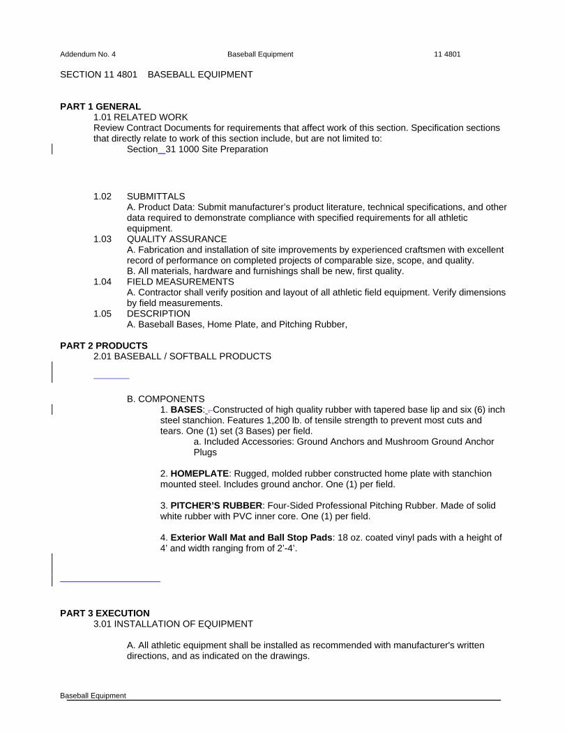
SECTION 11 4801 BASEBALL EQUIPMENT PART 1 GENERAL
1.01 RELATED WORK Review Contract Documents for requirements that affect work of this section. Specification sections that directly relate to work of this section include, but are not limited to:
Section 31 1000 Site Preparation
1.02 SUBMITTALS A. Product Data: Submit manufacturer’s product literature, technical specifications, and other data required to demonstrate compliance with specified requirements for all athletic equipment.
1.03 QUALITY ASSURANCE A. Fabrication and installation of site improvements by experienced craftsmen with excellent record of performance on completed projects of comparable size, scope, and quality.
B. All materials, hardware and furnishings shall be new, first quality. 1.04 FIELD MEASUREMENTS
A. Contractor shall verify position and layout of all athletic field equipment. Verify dimensions by field measurements.
1.05 DESCRIPTION A. Baseball Bases, Home Plate, and Pitching Rubber,
PART 2 PRODUCTS
2.01 BASEBALL / SOFTBALL PRODUCTS
B. COMPONENTS
1. BASES: . Constructed of high quality rubber with tapered base lip and six (6) inch steel stanchion. Features 1,200 lb. of tensile strength to prevent most cuts and tears. One (1) set (3 Bases) per field.
a. Included Accessories: Ground Anchors and Mushroom Ground Anchor Plugs
2. HOMEPLATE: Rugged, molded rubber constructed home plate with stanchion mounted steel. Includes ground anchor. One (1) per field. 3. PITCHER’S RUBBER: Four-Sided Professional Pitching Rubber. Made of solid white rubber with PVC inner core. One (1) per field. 4. Exterior Wall Mat and Ball Stop Pads: 18 oz. coated vinyl pads with a height of 4’ and width ranging from of 2’-4’.
PART 3 EXECUTION
3.01 INSTALLATION OF EQUIPMENT
A. All athletic equipment shall be installed as recommended with manufacturer's written directions, and as indicated on the drawings.

Addendum No. 4 Baseball Equipment 11 4801
Baseball Equipment
END OF SECTION
BASEBALL BATTING CAGE SYSTEM Addendum No. 4
BATTING CAGE 11 6500
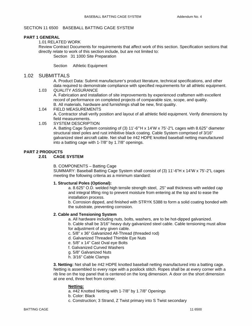
SECTION 11 6500 BASEBALL BATTING CAGE SYSTEM PART 1 GENERAL
1.01 RELATED WORK Review Contract Documents for requirements that affect work of this section. Specification sections that directly relate to work of this section include, but are not limited to:
Section 31 1000 Site Preparation
Section Athletic Equipment
1.02 SUBMITTALS A. Product Data: Submit manufacturer’s product literature, technical specifications, and other data required to demonstrate compliance with specified requirements for all athletic equipment.
1.03 QUALITY ASSURANCE A. Fabrication and installation of site improvements by experienced craftsmen with excellent record of performance on completed projects of comparable size, scope, and quality.
B. All materials, hardware and furnishings shall be new, first quality. 1.04 FIELD MEASUREMENTS
A. Contractor shall verify position and layout of all athletic field equipment. Verify dimensions by field measurements.
1.05 SYSTEM DESCRIPTION A. Batting Cage System consisting of (3) 11’-6”’H x 14’W x 75’-2”L cages with 8.625” diameter structural steel poles and rust inhibitive black coating. Cable System comprised of 3/16” galvanized steel aircraft cable. Net shall be #42 HDPE knotted baseball netting manufactured into a batting cage with 1-7/8” by 1.7/8” openings.
PART 2 PRODUCTS
2.01 CAGE SYSTEM
B. COMPONENTS – Batting Cage SUMMARY: Baseball Batting Cage System shall consist of (3) 11’-6”H x 14’W x 75’-2”L cages meeting the following criteria as a minimum standard:
1. Structural Poles (Optional): a. 8.625" O.D. welded high tensile strength steel, .25” wall thickness with welded cap and integral lifting ring to prevent moisture from entering at the top and to ease the installation process. b. Corrosion dipped, and finished with STRYK 5388 to form a solid coating bonded with the substrate, preventing corrosion.
2. Cable and Tensioning System a. All hardware including nuts, bolts, washers, are to be hot-dipped galvanized. b. Cable shall be 3/16” heavy duty galvanized steel cable. Cable tensioning must allow for adjustment of any given cable. c. 5/8” x 36” Galvanized All-Thread (threaded rod) d. Galvanized Threaded Thimble Eye Nuts e. 5/8” x 14” Cast Oval eye Bolts f. Galvanized Curved Washers g. 5/8” Galvanized Nuts h. 3/16” Cable Clamps
3. Netting: Net shall be #42 HDPE knotted baseball netting manufactured into a batting cage. Netting is assembled to every rope with a posilock stitch. Ropes shall be at every corner with a rib line on the top panel that is centered on the long dimension. A door on the short dimension at one end, three feet from corner.
Netting: a. #42 Knotted Netting with 1-7/8” by 1.7/8” Openings b. Color: Black c. Construction; 3 Strand, Z Twist primary into S Twist secondary

BASEBALL BATTING CAGE SYSTEM Addendum No. 4
BATTING CAGE 11 6500
d. Tensile: #42 twine, 220 pounds of breaking strength e. Anti UV Active Content: .02%
Rope: a. Diameter: 5/16” Twisted HDPE b. Tensile: 1430 pounds c. Color: Black
Hanging Twine: a. 210d/18 HDPE b. Tensile: 109 pounds of breaking strength c. Color: Black, twisted
4. Athletic Carpet: Synthetic Turf Model STI Multi Turf Pile Height 9/16”, Roll Width 15’ or approved equal 5. Synthetic Hitting Mat: 6’ x 14’; wide, nylon material that is spike proof with inlaid tufted white lines and inlaid tufted home plate to simulate batters box.
6. Accessories: a. ½ gallon STRYK-5388 touch up coating
C. COMPONENTS – Backstop SUMMARY: Baseball Backstop System shall be 40’x30’x40’ pole layout (per drawings) and meet the following criteria as a minimum standard:
1. Structural Poles: a. 8.625" O.D. welded high tensile strength steel, .25” wall thickness with welded cap and integral lifting ring to prevent moisture from entering at the top and to ease the installation process. b. Corrosion dipped, and finished with STRYK 5388 to form a solid coating bonded with the substrate, preventing corrosion. c. 7.5’ depth embedment, 30’ above ground level.
2. Cable and Tensioning System a. All hardware including nuts, bolts, washers, are to be hot-dipped galvanized. b. Cable shall be 3/16” heavy duty galvanized steel cable. c. Galvanized steel carabiners
3. Netting a. #42 HDPE twisted Knotted Netting b. 3.75” Stretch Mesh c. 1-7/8” Openings; netting Cut and Hung on Square d. Full rope border that is hand tied around the entire perimeter. e. Color: Black f. Yarn: 380 Denier, Extruded HDPE Fibers g. Tensile Avg: 220# breaking strength h. Construction: 3 strand, Z twist into S twist i. Melting Point: 248 to 266 Fahrenheit j. Net Sections: 3 individual net sections
4. Accessories: a. ½ gallon STRYK-5388 touch up coating
PART 3 EXECUTION
3.01 INSTALLATION OF EQUIPMENT A. All athletic equipment shall be installed as recommended by manufacturer, and as indicated on the drawings.
END OF SECTION
CDH-13072 Addendum No. 4
13 1220-1
SECTION 13 1220 METAL BUILDING SYSTEMS
PART 1 GENERAL 1.01 SUMMARY A. Furnish labor, equipment, material and services required for complete installation of metal
building systems as specified in this Section and as indicated on the drawings. B. This Section includes the following:
1. Structural framing. 2. Roof panels. 3. Wall panels and liners. 4. Service doors, frames, and hardware. 5. Louvers, vents, and ventilators. 6. Accessories and trim.
C. Related Sections include the following: 1. Division 03 Section "Concrete Work" for concrete foundations and anchor-bolt installation. 2. Division 04 Section "Concrete Unit Masonry" for interior partitions. 3. Division 05 Section "Light Steel Framing" for closed storage area. 4. Division 07 Section "Manufactured Roof and Wall Panels" for roof panels not standard with
metal building system manufacturer. 5. Division 08 Section "Overhead Coiling Doors." for service doors not provided by metal
building system manufacturer. 6. Division 08 Section "Finish Hardware" for finish door hardware and keying not standard
with metal building system manufacturer. 7. Division 09 Section "Painting" for shop-applied finishes not standard with metal building
system manufacturer. 1.02 REFERENCES A. National Insulation Association:
1. NIA-404 – Certified Faced Insulation Standard. B. North American Insulation Manufacturers Association:
1. NAIMA 202-96 (Rev. 2000) – Standard For Flexible Fiber Glass Insulation to be Laminated for Use in Metal Buildings.
1.03 DEFINITIONS A. Terminology Standard: Refer to MBMA's "Metal Building Systems Manual" for definitions of
terms for metal building system construction not otherwise defined in this Section or in referenced standards.
B. Bay Spacing: Dimension between main frames measured normal to frame (at centerline of frame) for interior bays, and dimension from centerline of first interior main frame measured perpendicular to end wall (outside face of end-wall girt).
C. Building Length: Dimension of the building measured perpendicular to main framing from end wall to end wall (outside face of girt to outside face of girt).
D. Building Width: Dimension of the building measured parallel to main framing from sidewall to sidewall (outside face of girt to outside face of girt).
E. Clear Span: Distance between supports of beams, girders, or trusses (measured from lowest level of connecting area of a column and a rafter frame, or knee).
F. Eave Height: Vertical dimension from finished floor to eave (the line along the sidewall formed by intersection of the planes of the roof and wall).
G. Clear Height under Structure: Vertical dimension from finished floor to lowest point of any part of primary or secondary structure, not including crane supports, located within clear span.
1.04 SYSTEM DESCRIPTION A. General: Provide a complete, integrated set of metal building system manufacturer's standard
mutually dependent components and assemblies that form a metal building system capable of withstanding structural and other loads, thermally induced movement, and exposure to weather without failure or infiltration of water into building interior. Include primary and secondary framing, roof and wall panels, and accessories complying with requirements indicated, including those in this Article. 1. Provide metal building system of size, spacing, slope, and spans indicated.
B. Primary Frame Type: 1. Rigid Clear Span: Solid-member structural-framing system without interior columns.
C. End-Wall Framing: Not required to be expandable. Provide load-bearing end-wall and corner columns, and rafters at one end only.

CDH-13072 Addendum No. 4
13 1220-2
D. Secondary Frame Type: Manufacturer's standard purlins and joists with exterior-framed (bypass) girts.
E. Roof System: Manufacturer's standard vertical-rib standing-seam roof panels with no insulation (typ).
F. Exterior Wall System: Manufacturer's standard field-assembled uninsulated wall panels. 1. See drawings for additional exterior wall components.
1.05 SYSTEM PERFORMANCE REQUIREMENTS A. Structural Performance: Provide metal building systems capable of withstanding the effects of
gravity loads and the following loads and stresses within limits and under conditions indicated: 1. Design Loads: Basic design loads, as well as auxiliary and collateral loads, shall meet the
minimum requirements of the authority having jurisdiction and as indicated in the Structural Drawings.
2. Design Loads: Basic design loads, as well as auxiliary and collateral loads, shall meet the minimum requirements of the authority having jurisdiction and as indicated below: a) Roof Live Loads: In accordance with the International Building Code, 2012 edition with
Amendments by state in which the Project is built. (Include loads induced by maintenance workers, materials, and equipment.)
b) Wind Load: 115 mph (ASCE 7-10 for Risk Category II) c) Snow Load: 10 psf d) Collateral Loads: 8 psf (Collateral loads include additional dead loads such as fire
protection systems, ceilings, lights, and mechanical systems.) e) Load Combinations: Design metal building systems to withstand the most critical
effects of load factors and load combinations. 3. Deflection Limits: Engineer assemblies to withstand design loads with deflections no
greater than the following: a) Purlins and Rafters: Vertical deflection of 1/240 of the span. b) Girts: Horizontal deflection of 1/240 of the span. c) Roof Panels: Vertical deflection 1/240 of the span. d) Wall Panels: Horizontal deflection of 1/240 of the span. e) Design secondary framing system to accommodate deflection of primary building
structure and construction tolerances, and to maintain clearances at openings. B. Seismic Performance: Design and engineer metal building systems capable of withstanding
the effects of earthquake motions determined according to the International Building Code 2012, Table 1613.5.6(1) and 1613.5.6(2), Seismic Site Class C.
C. Thermal Movements: Provide metal building roof and wall panel systems that allow for thermal movements resulting from the following maximum change (range) in ambient and surface temperatures by preventing buckling, opening of joints, overstressing of components, failure of joint sealants, failure of connections, and other detrimental effects. Base engineering calculation on surface temperatures of materials due to both solar heat gain and nighttime-sky heat loss. 1. Temperature Change (Range): 120 deg F (67 deg C), ambient; 180 deg F (100 deg C),
material surfaces. D. Water Penetration for Roof Panels: Provide roof panel assemblies with no water penetration
as defined in the test method when tested according to ASTM E 1646 at a minimum differential pressure of 20 percent of inward-acting, wind-load design pressure of not less than 6.24 lbf/sq. ft. (300 Pa) and not more than 12 lbf/sq. ft. (575 Pa).
E. Water Penetration for Wall Panels: Provide wall panel assemblies with no water penetration as defined in the test method when tested according to ASTM E 331 at a minimum differential pressure of 20 percent of inward-acting, wind-load design pressure of not less than 6.24 lbf/sq. ft. (300 Pa) and not more than 12 lbf/sq. ft. (575 Pa).
F. Wind-Uplift Resistance: Provide roof panel assemblies that meet requirements of UL 580 for Class 1-60 wind-uplift resistance.
1.06 SUBMITTALS A. Product Data: Include construction details, material descriptions, dimensions of individual
components and profiles, and finishes for each type of metal building system component. B. Shop Drawings: For the following metal building system components. Include plans,
elevations, sections, details, and attachments to other Work. 1. For installed products indicated to comply with design loads, include structural analysis
data signed and sealed by the qualified professional engineer responsible for their preparation.

CDH-13072 Addendum No. 4
13 1220-3
2. Anchor-Bolt Plans: Submit anchor-bolt plans before foundation work begins. Include location, diameter, and projection of anchor bolts required to attach metal building to foundation. Indicate column reactions at each location.
3. Structural-Framing Drawings: Show complete fabrication of primary and secondary framing; including provisions for openings. Indicate welds and bolted connections, distinguishing between shop and field applications. Include transverse cross-sections. a) Show provisions for attaching roof curbs, service walkways, platforms, and pipe racks.
4. Roof and Wall Panel Layout Drawings: Show layouts of panels on support framing, details of edge conditions, joints, panel profiles, corners, custom profiles, supports, anchorages, trim, flashings, closures, and special details. Distinguish between factory and field assembled work.
5. Personnel Door Schedule: Where doors and frames are to be provided under this section, provide schedule of doors and frames, using the same reference numbers as indicated on Drawings. Include details of reinforcement and installation requirements for finish hardware.
6. Accessory Drawings: Include details of the following items: a) Flashing and trim. b) Gutters. c) Downspouts. d) Louvers. e) Service walkways.
C. Samples for Initial Selection: 1. Manufacturer's color charts showing the full range of colors available for each type of
component with factory-applied color finishes. 2. Proposed vapor retarders, if made a part of this Specification.
D. Letter of Design Certification: Signed and sealed by a qualified professional engineer licensed in the state in which the Project is built.
E. Maintenance Data: For metal panel finishes and door hardware to include in maintenance manuals.
1.07 QUALITY ASSURANCE A. Erector Qualifications: An experienced erector who has specialized in erecting and installing
work similar in material, design, and extent to that indicated for this Project and who is acceptable to manufacturer.
B. Professional Engineer Qualifications: A professional engineer who is legally qualified to practice in jurisdiction where Project is located and who is experienced in providing engineering services of the kind indicated. Engineering services are defined as those performed for installations of metal building systems that are similar to those indicated for this Project in material, design, and extent.
C. Manufacturer Qualifications: A firm experienced in manufacturing metal building systems similar to those indicated for this Project, with a record of successful in-service performance, and a member of MBMA (Metal Building Manufacturer’s Association).
D. Engineering Responsibility: Preparation of Shop Drawings, testing program development, test result interpretation, and comprehensive engineering analysis by a qualified professional engineer.
E. Source Limitations: Obtain each type of metal building system component through one source from a single manufacturer.
F. Welding: Qualify procedures and personnel according to AWS D1.1, "Structural Welding Code--Steel"; and AWS D1.3, "Structural Welding Code--Sheet Steel."
G. Structural Steel: Comply with AISC S335, "Specification for Structural Steel Buildings--Allowable Stress Design, Plastic Design"; or AISC S342, "Load and Resistance Factor Design Specification for Structural Steel Buildings," for design requirements and allowable stresses.
H. Cold-Formed Steel: Comply with AISI SG-671, "Specification for the Design of Cold-Formed Steel Structural Members," and AISI SG-911, "Load and Resistance Facet Design Specification for Steel Structural Members," for design requirements and allowable stresses.
1.08 DELIVERY, STORAGE, AND HANDLING A. Deliver components, sheets, panels, and other manufactured items so as not to be damaged
or deformed. Package roof and wall panels for protection during transportation and handling. B. Handling: Unload, store, and erect roof and wall panels to prevent bending, warping, twisting,
and surface damage. C. Stack materials on platforms or pallets, covered with tarpaulins or other suitable weathertight
and ventilated covering. Store roof and wall panels to ensure dryness. Do not store panels in contact with other materials that might cause staining, denting, or other surface damage.
CDH-13072 Addendum No. 4
13 1220-4
1.09 PROJECT CONDITIONS A. Weather Limitations: Proceed with installation only when weather conditions permit roof and
wall panel installation to be performed according to manufacturer's written instructions and warranty requirements.
B. Field Measurements: Verify metal building system foundations by field measurements before metal building fabrication and indicate measurements on Shop Drawings. Coordinate fabrication schedule with construction progress to avoid delaying the Work.
1.10 WARRANTY A. General Warranty: Special warranties specified in this Article shall not deprive Owner of other
rights Owner may have under other provisions of the Contract Documents and shall be in addition to, and run concurrent with, other warranties made by Contractor under requirements of the Contract Documents.
B. Special Warranty on Metal Panel Finishes: Manufacturer's standard form in which manufacturer agrees to repair finish or replace metal panels that show evidence of deterioration of factory-applied finishes within specified warranty period. 1. Siliconized Polyester Finish: Deterioration includes, but is not limited to, the following:
a) Color fading more than 15 Hunter units when tested according to ASTM D 2244. b) Chalking in excess of a No. 2 rating when tested according to ASTM D 4214. c) Cracking, checking, peeling, or failure of paint to adhere to bare metal.
2. Fluoropolymer Finish: Deterioration includes, but is not limited to, the following: a) Color fading more than 5 Hunter units when tested according to ASTM D 2244. b) Chalking in excess of a No. 8 rating when tested according to ASTM D 4214. c) Cracking, checking, peeling, or failure of paint to adhere to bare metal.
3. Warranty Period: 20 years from date of Substantial Completion for fluoropolymer finishes; 10 years from date of Substantial Completion for siliconized polyester.
C. Special Warranty on Standing-Seam Roof Panel Weathertightness: Written warranty, signed by manufacturer agreeing to repair or replace standing-seam roof panel assemblies that fail to remain weathertight within specified warranty period. 1. Warranty Period: 15 years from date of Substantial Completion.
PART 2 PRODUCTS 2.01 MANUFACTURERS A. Acceptable Manufactures:
1. Metal Building Systems: Subject to compliance with requirements of these Specifications, provide products from one of the following: a) ABCO-American, Inc. b) American Steel Building Co., Inc. c) American Steel Buildings d) Butler Manufacturing Co. e) Kirby Building Systems, Inc. f) Lifetime Steel Buildings, Inc. g) Star Buildings Division, H.H. Robertson Co. h) Steelox Systems i) Varco-Pruden Buildings j) Whirlwind Steel Buildings, Inc.
2.02 STRUCTURAL-FRAMING MATERIALS A. W-Shapes: ASTM A 992/A 992M; ASTM A 572/A 572M, Grade 50 or 55 (345 or 380); or
ASTM A 529/A 529M, Grade 50 or 55 (345 or 380). B. Channels, Angles, M-Shapes, and S-Shapes: ASTM A 36/A 36M; ASTM A 572/A 572M,
Grade 50 or 55 (345 or 380); or ASTM A 529/A 529M, Grade 50 or 55 (345 or 380) C. Plate and Bar: ASTM A 36/A 36M; ASTM A 572/A 572M, Grade 50 or 55 (345 or 380); or
ASTM A 529/A 529M, Grade 50 or 55 (345 or 380) D. Steel Tubing or Pipe: ASTM A 500, Grade B; ASTM A 501; or ASTM A 53, Grade B. E. Structural-Steel Sheet: Hot-rolled, ASTM A 570/A 570M, Grade 50 or Grade 55; hot-rolled,
ASTM 568/A 568M; or cold-rolled, ASTM A 611, structural-quality, matte (dull) finish. F. Zinc-Coated (Galvanized) Steel Sheet: ASTM A 653/A 653M, structural quality, Grade 50, with
G60 (Z180) coating designation; mill phosphatized. G. Metallic-Coated Steel Sheet Prepainted with Coil Coating: Steel sheet metallic coated by the
hot-dip process and prepainted by the coil-coating process to comply with ASTM A 755/A 755M and the following requirements: 1. Zinc-Coated (Galvanized) Steel Sheet: ASTM A 653/A 653M, G90 (Z275) coating
designation; structural quality.
CDH-13072 Addendum No. 4
13 1220-5
2. Aluminum-Zinc Alloy-Coated Steel Sheet: ASTM A 792/A 792M, Structural Steel (SS), Grade 50 or 80 (340 or 550); with Class AZ50 (AZM150) coating.
H. Non-High-Strength Bolts, Nuts, and Washers: ASTM A 307, Grade A (ASTM F 568M, Property Class 4.6); carbon-steel, hex-head bolts; carbon-steel nuts; and flat, unhardened steel washers. 1. Finish: Hot-dip zinc coating, ASTM A 153, Class C.
I. High-Strength Bolts, Nuts, and Washers: ASTM A 325 (ASTM A 325M), Type 1, heavy hex steel structural bolts, heavy hex carbon-steel nuts, and hardened carbon-steel washers. 1. Finish: Hot-dip zinc coating, ASTM A 153, Class C.
J. Anchor Rods, Bolts, Nuts, and Washers: As follows: 1. Unheaded Rods: ASTM A 36/A 36M. 2. Unheaded Bolts: ASTM A 687, high strength. 3. Headed Bolts: ASTM A 325 (ASTM A 325M), Type 1, heavy hex steel structural bolts and
heavy hex carbon-steel nuts. 4. Washers: ASTM A 36/A 36M. 5. Primer: As selected by manufacturer for resistance to normal atmospheric corrosion,
compatibility with finish paint systems, capability to provide a sound foundation for field-applied topcoats despite prolonged exposure, and as follows: a) Fast-curing, lead- and chromate-free, universal modified-alkyd primer; complying with
performance requirements of FS TT-P-664. 2.03 PANEL MATERIALS A. Metallic-Coated Steel Sheet Prepainted with Coil Coating: Steel sheet metallic coated by the
hot-dip process and prepainted by the coil-coating process to comply with ASTM A 755/A 755M and one of the following requirements: 1. Zinc-Coated (Galvanized) Steel Sheet: ASTM A 653/A 653M, Structural Steel (SS),
Grades 33 through 80 (230 through 550), with G90 (Z275) coating designation. 2. Aluminum-Zinc Alloy-Coated Steel Sheet: ASTM A 792/A 792M, Structural Steel (SS),
Grade 50 or 80 (340 or 550); with Class AZ50 (AZM150) coating designation. 3. Exposed Finishes: Apply the following coil coating, as specified or indicated on Drawings:
a) Acrylic-Enamel Coating: Epoxy primer and acrylic-enamel topcoat; with a dry film thickness of not less than 0.2 mil (0.005 mm) for primer and 0.8 mil (0.02 mm) for topcoat.
b) Siliconized-Polyester Coating: Epoxy primer and silicone-modified, polyester-enamel topcoat; with a dry film thickness of not less than 0.2 mil (0.005 mm) for primer and 0.8 mil (0.02 mm) for topcoat.
c) High-Performance Organic Finish (2-Coat Fluoropolymer): AA-C12C40R1x (Chemical Finish: cleaned with inhibited chemicals; Chemical Finish: conversion coating; Organic Coating: manufacturer's standard 2-coat, thermocured system consisting of specially formulated inhibitive primer and fluoropolymer color topcoat containing not less than 70 percent polyvinylidene fluoride resin by weight). Prepare, pretreat, and apply coating to exposed metal surfaces to comply with AAMA 2605 and with coating and resin manufacturers' written instructions.
d) High-Performance Organic Finish (3-Coat Fluoropolymer): AA-C12C40R1x (Chemical Finish: cleaned with inhibited chemicals; Chemical Finish: conversion coatings; Organic Coating: manufacturer's standard 3-coat, thermocured system consisting of specially formulated inhibitive primer, fluoropolymer color coat, and clear fluoropolymer topcoat, with both color coat and clear topcoat containing not less than 70 percent polyvinylidene fluoride resin by weight), with a minimum total dry film thickness of 1.5 mil (0.038 mm). Prepare, pretreat, and apply coating to exposed metal surfaces to comply with AAMA 2605 and with coating and resin manufacturers' written instructions.
4. Concealed Finish: Apply pretreatment and manufacturer's standard white or light-colored backer finish, consisting of prime coat and wash coat with a total minimum dry film thickness of 0.5 mil (0.013 mm).
2.04 DOOR AND FRAME MATERIALS A. Cold-Rolled Steel Sheet: ASTM A 1008/A 1008M, Commercial Steel (CS), Type B, suitable
for exposed applications. B. Metallic-Coated Steel Sheet: ASTM A 653/A 653M, Commercial Steel (CS), Type B; with G60
(Z180) zinc (galvanized) or A60 (ZF180) zinc-iron-alloy (galvannealed) coating designation. 2.05 MISCELLANEOUS MATERIALS A. Fasteners: Self-tapping screws, bolts, nuts, self-locking rivets and bolts, end-welded studs,
and other suitable fasteners designed to withstand design loads. Provide fasteners with heads
CDH-13072 Addendum No. 4
13 1220-6
matching color of materials being fastened by means of plastic caps or factory-applied coating. 1. Fasteners for Metal Roof and Wall Panels: Self-drilling Type 410 stainless-steel or self-
tapping Type 304 stainless-steel or zinc-alloy-steel hex washer head, with EPDM or PVC washer under heads of fasteners bearing on weather side of metal panels.
2. Fasteners for Flashing and Trim: Blind fasteners or self-drilling screws with hex washer head.
3. Blind Fasteners: High-strength aluminum or stainless-steel rivets. B. Nonmetallic, Shrinkage-Resistant Grout: ASTM C 1107, factory-packaged, nonmetallic
aggregate grout, noncorrosive, nonstaining, mixed with water to consistency suitable for application and a 30-minute working time.
C. Metal Panel Sealants: 1. Sealant Tape: Pressure-sensitive, 100 percent solids, gray polyisobutylene compound
sealant tape with release-paper backing. Provide permanently elastic, nonsag, nontoxic, nonstaining tape of manufacturer's standard size.
2. Joint Sealant: ASTM C 920; one-part elastomeric polyurethane, polysulfide, or silicone-rubber sealant; of type, grade, class, and use classifications required to seal joints in metal panels and remain weathertight; and as recommended by metal building system manufacturer.
D. Snow and Ice Waterproofing Underlayment: 1. Acceptable Manufacturers/Products: Subject to compliance with the requirements of these
Specifications, provide products from the following: a) GAF Corp. - Stormguard HT b) Grace Construction Products - Vycor Ice & Water Shield.
2. Self-adhering waterproofing membrane meeting ASTM D1970, composed of reinforcement that is impregnated and coated with rubberized asphalt. Minimum 60 mil. thickness, top surface coated with fine granules. Suitable for UL Class A applications.
E. Pipe Roof Penetration Flashing: 1. Acceptable Manufacturers: Subject to compliance with the requirements of these
Specifications, provide products from the following: a) Construction Fasteners Inc.; Flashers
2. Provide flexible EPDM rubber flashing boots with provision for various pipe sizes within a particular boot size. Provide with capability to fit any roof profile and with an integral aluminum base flange that can be bent and fitted. Provide flashing resistant to ultraviolet light, cracking and weathering.
2.06 FABRICATION, GENERAL A. General: Design components and field connections required for erection to permit easy
assembly. 1. Mark each piece and part of the assembly to correspond with previously prepared erection
drawings, diagrams, and instruction manuals. 2. Fabricate structural framing to produce clean, smooth cuts and bends. Punch holes of
proper size, shape, and location. Members shall be free of cracks, tears, and ruptures. B. Tolerances: Comply with MBMA's "Metal Building Systems Manual": Chapter IV, Section 9,
"Fabrication and Erection Tolerances." C. Metal Panels: Fabricate and finish metal panels at the factory to greatest extent possible, by
manufacturer's standard procedures and processes, as necessary to fulfill indicated performance requirements. Comply with indicated profiles and with dimensional and structural requirements. Provide panel profile, including major ribs and intermediate stiffening ribs, if any, for full length of metal panel.
2.07 STRUCTURAL FRAME FABRICATION A. General:
1. Primary Framing: Shop fabricate framing components to indicated size and section with baseplates, bearing plates, stiffeners, and other items required for erection welded into place. Cut, form, punch, drill, and weld framing for bolted field assembly. a) Make shop connections by welding or by using high-strength bolts. b) Join flanges to webs of built-up members by a continuous submerged arc-welding
process. c) Brace compression flange of primary framing with steel angles or cold-formed structural
tubing between frame web and purlin or girt web, so flange compressive strength is within allowable limits for any combination of loadings.
d) Weld clips to frames for attaching secondary framing members, if permitted by authorities having jurisdiction.

CDH-13072 Addendum No. 4
13 1220-7
e) Shop Priming: Prepare surfaces for shop priming according to SSPC-SP 2. Shop prime primary structural members with specified primer after fabrication.
2. Secondary Framing: Shop fabricate framing components to indicated size and section by roll-forming or break-forming, with baseplates, bearing plates, stiffeners, and other plates required for erection welded into place. Cut, form, punch, drill, and weld secondary framing for bolted field connections to primary framing. a) Make shop connections by welding or by using non-high-strength bolts. b) Shop Priming: Prepare uncoated surfaces for shop priming according to SSPC-SP 2.
Shop prime uncoated secondary structural members with specified primer after fabrication.
B. Primary Framing: Manufacturer's standard structural primary framing system, designed to withstand required loads and specified requirements. Primary framing includes transverse and lean-to frames; rafter, rake, and canopy beams; sidewall, intermediate, end-wall, and corner columns; and wind bracing. 1. General: Provide frames with attachment plates, bearing plates, and splice members.
Factory drill for field-bolted assembly. Provide frame span and spacing indicated. 2. Exterior Column Type: Uniform depth 3. Rafter Type: Uniform depth
C. End-Wall Framing: Manufacturer's standard primary end-wall framing fabricated for field-bolted assembly to comply with the following: 1. End-Wall and Corner Columns: I-shaped sections fabricated from structural-steel shapes;
shop-welded, built-up steel plates; or C-shaped, cold-formed, structural-steel sheet; with minimum thickness of 0.0598 inch (1.5 mm).
D. Secondary Framing: Manufacturer's standard secondary framing members, including purlins, girts, eave struts, flange bracing, base members, gable angles, clips, headers, jambs, and other miscellaneous structural members. Fabricate framing from cold-formed, structural-steel sheet or roll-formed, metallic-coated steel sheet prepainted with coil coating, unless otherwise indicated, to comply with the following: 1. Purlins: C- or Z-shaped sections; fabricated from minimum 0.0598 inch (1.5 mm) thick
steel sheet, built-up steel plates, or structural-steel shapes; minimum 2-1/2 inch (64 mm) wide flanges.
2. Girts: C or Z-shaped sections; fabricated from minimum 0.0598 inch (1.5 mm) thick steel sheet, built-up steel plates, or structural-steel shapes. Form ends of Z-sections with stiffening lips angled 40 to 50 degrees to flange and with minimum 2-1/2 inch (64 mm) wide flanges.
3. Eave Struts: Unequal-flange, C-shaped sections; fabricated from 0.0598 inch (1.5 mm) thick steel sheet, built-up steel plates, or structural-steel shapes; to provide adequate backup for metal panels.
4. Flange Bracing: Minimum 2 by 2 by 1/8 inch (51 by 51 by 3 mm) structural-steel angles or 1 inch (25 mm) diameter, cold-formed structural tubing to stiffen primary frame flanges.
5. Sag Bracing: Minimum 1 by 1 by 1/8 inch (25 by 25 by 3 mm) structural-steel angles. 6. Base or Sill Angles: Minimum 3 by 2 by 0.0598 inch (76 by 51 by 1.5 mm) zinc-coated
(galvanized) steel sheet. 7. Purlin and Girt Clips: Minimum 0.0598 inch (1.5 mm) thick, steel sheet. Provide
galvanized clips where clips are connected to galvanized framing members. 8. Secondary End-Wall Framing: Manufacturer's standard sections fabricated from minimum
0.0598 inch (1.5 mm) thick, structural-steel sheet. 9. Framing for Openings: Channel shapes; fabricated from minimum 0.0598 inch (1.5 mm)
thick, cold-formed, structural-steel sheet or structural-steel shapes. Frame head and jamb of door openings, and head, jamb, and sill of other openings.
10. Miscellaneous Structural Members: Manufacturer's standard sections fabricated from cold-formed, structural-steel sheet; built-up steel plates; or zinc-coated (galvanized) steel sheet; designed to withstand required loads.
E. Canopy Framing: Manufacturer's standard structural-framing system, designed to withstand required loads, fabricated from shop-welded, built-up steel plates or structural-steel shapes. Provide frames with attachment plates and splice members, factory drilled for field-bolted assembly. Provide configuration as indicated.
F. Bracing: Provide adjustable wind bracing as follows: 1. Rods: ASTM A 36/A 36M; ASTM A 572/A 572M, Grade 50 (345); or ASTM A 529/A 529M,
Grade 50 (345); minimum 1/2 inch (13 mm) diameter steel; threaded full length or threaded a minimum of 6 inches (152 mm) at each end.
CDH-13072 Addendum No. 4
13 1220-8
2. Cable: ASTM A 475, 1/4 inch (6 mm) diameter, extra-high-strength grade, Class B zinc-coated, 7-strand steel; with threaded end anchors.
3. Angles: Fabricated from structural-steel shapes to match primary framing, of size required to withstand design loads.
4. Rigid Portal Frames: Fabricate from shop-welded, built-up steel plates or structural-steel shapes to match primary framing; of size required to withstand design loads.
5. Fixed-Base Columns: Fabricate from shop-welded, built-up steel plates or structural-steel shapes to match primary framing; of size required to withstand design loads.
G. Bolts: Provide plain finish bolts for structural-framing components that are primed or finish painted. Provide hot-dipped galvanized bolts for structural-framing components that are galvanized.
H. Factory-Primed Finish: Apply specified primer immediately after cleaning and pretreating to a minimum thickness of 1 mil.
2.08 METAL ROOF PANEL FABRICATION A. Vertical-Rib, Standing-Seam Metal Roof Panels: Formed with vertical ribs at panel edges and
intermediate stiffening ribs symmetrically spaced between ribs; designed for sequential installation by mechanically attaching panels to supports using concealed clips located under one side of panels and engaging opposite edge of adjacent panels. 1. Material: Aluminum-zinc alloy-coated steel sheet. 2. Thickness: 0.0209 inch (0.55 mm) 3. Surface Texture: Smooth, flat 4. Exterior Finish: Siliconized polyester or acrylic enamel. 5. Color: As selected by Architect from manufacturer’s full range. 6. Clips: Manufacturer’s standard floating type to accommodated thermal movement,
fabricated from stainless steel sheet. 7. Panel Width: Maximum 24 inches (610 mm)
2.09 FIELD-ASSEMBLED METAL WALL PANEL FABRICATION A. Concealed-Fastener Metal Wall Panels: Formed with vertical panel edges and a single wide
recess, centered between panel edges; with flush joint between panels; with 1 inch (25 mm) wide flange for attaching interior finish; designed to be field assembled by lapping and interconnecting side edges of adjacent panels and mechanically attaching through panel to supports using concealed fasteners and factory-applied sealant in side laps. 1. Material: Aluminum-zinc alloy-coated steel sheet. 2. Thickness: 0.0269 inch (0.70 mm) 3. Exterior Finish: Siliconized polyester or acrylic enamel. 4. Surface Texture: Smooth, flat 5. Color: As selected by Architect from manufacturer’s full range. 6. Panel Coverage: 16 inches (406 mm) 7. Panel Height: 3 inches (76 mm)
B. Tapered-Rib-Profile, Metal Liner Panels: Formed with raised, trapezoidal major ribs and flat pan between major ribs; designed to be field assembled by lapping side edges of adjacent panels and mechanically attaching panels to supports using exposed fasteners in side laps. 1. Material: Aluminum-zinc alloy-coated steel sheet. 2. Thickness: 0.0209 inch (0.55 mm) 3. Exterior Finish: Siliconized polyester or acrylic enamel 4. Color: As selected by Architect from manufacturer’s full range. 5. Major-Rib Spacing: 12 inches (305 mm) o.c. 6. Panel Coverage: 36 inches (914 mm) 7. Panel Height: 1.25 inches (32 mm)
2.10 ACCESSORIES A. General: Provide accessories as standard with metal building system manufacturer and as
specified. Fabricate and finish accessories at the factory to greatest extent possible, by manufacturer's standard procedures and processes. Comply with indicated profiles and with dimensional and structural requirements. 1. Form exposed sheet metal accessories that are without excessive oil canning, buckling,
and tool marks and that are true to line and levels indicated, with exposed edges folded back to form hems.
B. Roof Panel Accessories: Provide components required for a complete metal roof panel assembly including copings, fasciae, corner units, ridge closures, clips, sealants, gaskets, fillers, closure strips, and similar items. Match material and finish of metal roof panels, unless otherwise indicated.
CDH-13072 Addendum No. 4
13 1220-9
1. Metal Closures: Provide closures at eaves and ridges, fabricated of same material as metal roof panels.
2. Closure Strips: Closed-cell, expanded, cellular, rubber or crosslinked, polyolefin-foam or closed-cell laminated polyethylene; minimum 1 inch (25 mm) thick, flexible closure strips; cut or premolded to match metal roof panel profile. Provide closure strips where indicated or necessary to ensure weathertight construction.
C. Wall Panel Accessories: Provide components required for a complete metal wall panel assembly including copings, fasciae, mullions, sills, corner units, clips, sealants, gaskets, fillers, closure strips, and similar items. Match material and finish of metal wall panels, unless otherwise indicated. 1. Metal Closures: Provide closures at eaves and ridges, fabricated of same material as
metal roof panels. 2. Closure Strips: Closed-cell, expanded, cellular, rubber or crosslinked, polyolefin-foam or
closed-cell laminated polyethylene; minimum 1 inch (25 mm) thick, flexible closure strips; cut or premolded to match metal wall panel profile. Provide closure strips where indicated or necessary to ensure weathertight construction.
D. Flashing and Trim: Formed from minimum 0.0159 inch (0.40 mm) thick, metallic-coated steel sheet or aluminum-zinc alloy-coated steel sheet prepainted with coil coating; finished to match adjacent metal panels. 1. Provide flashing and trim as required to seal against weather and to provide finished
appearance. Locations include, but are not limited to, eaves, rakes, corners, bases, framed openings, ridges, fasciae, and fillers.
2. Opening Trim: Minimum 0.0269 inch (0.70 mm) thick, metallic-coated steel sheet or aluminum-zinc alloy-coated steel sheet prepainted with coil coating. Trim head and jamb of door openings, and head, jamb, and sill of other openings.
E. Gutters: Formed from minimum 0.0159 inch (0.40 mm) thick, metallic-coated steel sheet or aluminum-zinc alloy-coated steel sheet prepainted with coil coating; finished to match roof fascia and rake trim. Match profile of gable trim, complete with end pieces, outlet tubes, and other special pieces as required. Fabricate in minimum 96-inch- (2438-mm-) long sections, sized according to SMACNA's "Architectural Sheet Metal Manual."
F. Downspouts: Formed from 0.0159 inch (0.4 mm) thick, zinc-coated (galvanized) steel sheet or aluminum-zinc alloy-coated steel sheet prepainted with coil coating; finished to match metal wall panels. Fabricate in minimum 10 foot (3 m) long sections, complete with formed elbows and offsets.
2.11 SOURCE QUALITY CONTROL A. Special Inspector: Owner will engage a qualified special inspector to perform the following
tests and inspections and to submit reports. Special Inspector will verify that manufacturer maintains detailed fabrication and quality-control procedures and will review the completeness and adequacy of those procedures to perform the Work. 1. Special inspections will not be required if fabrication is performed by a manufacturer
registered and approved by authorities having jurisdiction to perform such Work without special inspection.
2. Welded Connections: In addition to visual inspection, shop-welded connections shall be tested and inspected according to AWS D1.1
PART 3 EXECUTION 3.01 EXAMINATION A. Examine substrates, areas, and conditions, with Erector present, for compliance with
requirements for installation tolerances and other conditions affecting performance of work. B. Before erection proceeds, survey elevations and locations of concrete and masonry bearing
surfaces and locations of anchor rods, bearing plates, and other embedments to receive structural framing, with Erector present, for compliance with requirements and metal building system manufacturer's tolerances.
C. Proceed with erection only after unsatisfactory conditions have been corrected. 3.02 PREPARATION A. Clean and prepare surfaces to be painted according to manufacturer's written instructions for
each particular substrate condition. B. Provide temporary shores, guys, braces, and other supports during erection to keep structural
framing secure, plumb, and in alignment against temporary construction loads and loads equal in intensity to design loads. Remove temporary supports when permanent structural framing, connections, and bracing are in place, unless otherwise indicated.
3.03 ERECTION OF STRUCTURAL FRAMING
CDH-13072 Addendum No. 4
13 1220-10
A. Erect metal building system according to manufacturer's written erection instructions and approved erection shop drawings.
B. Do not field cut, drill, or alter structural members without written approval from metal building system manufacturer's professional engineer.
C. Set structural framing accurately in locations and to elevations indicated and according to AISC specifications referenced in this Section. Maintain structural stability of frame during erection.
D. Base and Bearing Plates: Clean concrete- and masonry-bearing surfaces of bond-reducing materials, and roughen surfaces prior to setting plates. Clean bottom surface of plates. 1. Set plates for structural members on wedges, shims, or setting nuts as required. 2. Tighten anchor rods after supported members have been positioned and plumbed. Do not
remove wedges or shims but, if protruding, cut off flush with edge of plate before packing with grout.
3. Promptly pack grout solidly between bearing surfaces and plates so no voids remain. Neatly finish exposed surfaces; protect grout and allow to cure. Comply with manufacturer's written installation instructions for shrinkage-resistant grouts.
E. Align and adjust structural framing before permanently fastening. Before assembly, clean bearing surfaces and other surfaces that will be in permanent contact with framing. Perform necessary adjustments to compensate for discrepancies in elevations and alignment. 1. Level and plumb individual members of structure. 2. Make allowances for difference between temperature at time of erection and mean
temperature when structure will be completed and in service. F. Primary Framing and End Walls: Erect framing true to line, level, plumb, rigid, and secure.
Level baseplates to a true even plane with full bearing to supporting structures, set with double-nutted anchor bolts. Use grout to obtain uniform bearing and to maintain a level base-line elevation. Moist cure grout for not less than seven days after placement. 1. Make field connections using high-strength bolts installed according to RCSC's
"Specification for Structural Joints Using ASTM A 325 or A 490 Bolts" for type of bolt and type of joint specified.
G. Secondary Framing: Erect framing true to line, level, plumb, rigid, and secure. Fasten secondary framing to primary framing using clips with field connections using non-high-strength bolts. 1. Provide rake or gable purlins with tight-fitting closure channels and fasciae. 2. Locate and space wall girts to suit openings such as doors and windows. 3. Provide supplemental framing at entire perimeter of openings, including doors, windows,
louvers, ventilators, and other penetrations of roof and walls. H. Bracing: Install bracing in roof and sidewalls where indicated on erection drawings.
1. Tighten rod and cable bracing to avoid sag. 2. Locate interior end-bay bracing only where indicated.
I. Framing for Openings: Provide shapes of proper design and size to reinforce openings and to carry loads and vibrations imposed, including equipment furnished under mechanical and electrical work. Securely attach to structural framing.
J. Erection Tolerances: Maintain erection tolerances of structural framing within AISC's "Code of Standard Practice for Steel Buildings and Bridges."
3.04 METAL PANEL INSTALLATION, GENERAL A. Examination: Examine primary and secondary framing to verify that structural panel support
members and anchorages have been installed within alignment tolerances required by manufacturer. 1. Examine roughing-in for components and systems penetrating metal panels to verify actual
locations of penetrations relative to seam locations of metal panels before metal panel installation.
B. General: Anchor metal panels and other components of the Work securely in place, with provisions for thermal and structural movement. 1. Field cut metal panels as required for doors, windows, and other openings. Cut openings
as small as possible, neatly to size required, and without damage to adjacent metal panel finishes. Field cutting of metal panels by torch is not permitted unless approved in writing by manufacturer.
2. Install metal panels perpendicular to structural supports, unless otherwise indicated. 3. Flash and seal metal panels with weather closures at perimeter of openings and similar
elements. Fasten with self-tapping screws. 4. Locate and space fastenings in uniform vertical and horizontal alignment.
CDH-13072 Addendum No. 4
13 1220-11
5. Locate metal panel splices over, but not attached to, structural supports with end laps in alignment. Stagger panel splices and end laps to avoid a four-panel lap splice condition.
6. Lap metal flashing over metal panels to allow moisture to run over and off the material. C. Lap-Seam Metal Panels: Install screw fasteners with power tools having controlled torque
adjusted to compress neoprene washer tightly without damage to washer, screw threads, or metal panels. Install screws in predrilled holes.
D. Metal Protection: Where dissimilar metals will contact each other or corrosive substrates, protect against galvanic action by painting contact surfaces with bituminous coating, by applying rubberized-asphalt underlayment to each contact surface, or by other permanent separation as recommended by metal roof panel manufacturer.
E. Joint Sealers: Install gaskets, joint fillers, and sealants where indicated and where required for weatherproof performance of metal panel assemblies. Provide types of gaskets, fillers, and sealants indicated or, if not indicated, types recommended by metal panel manufacturer. 1. Seal metal panel end laps with double beads of tape or sealant, full width of panel. Seal
side joints where recommended by metal panel manufacturer. 3.05 METAL ROOF PANEL INSTALLATION A. General: Provide metal roof panels of full length from eave to ridge, unless otherwise
indicated or restricted by shipping limitations. 1. Install ridge and hip caps as metal roof panel work proceeds. 2. Flash and seal metal roof panels with weather closures at eaves and rakes. Fasten with
self-tapping screws. B. Field-Assembled, Standing-Seam Metal Roof Panels: Fasten metal roof panels to supports
with concealed clips at each standing-seam joint at location, spacing, and with fasteners recommended by manufacturer. 1. Install clips to supports with self-tapping fasteners. 2. Install pressure plates at locations indicated in manufacturer's written installation
instructions. 3. Snap Joint: Nest standing seams and fasten together by interlocking and completely
engaging factory-applied sealant. 4. Seamed Joint: Crimp standing seams with manufacturer-approved motorized seamer tool
so clip, metal roof panel, and factory-applied sealant are completely engaged. 5. Rigidly fasten eave end of metal roof panels and allow ridge end free movement due to
thermal expansion and contraction. Predrill panels for fasteners. 6. Provide metal closures at peaks, rake edges, rake walls, and each side of ridge and hip
caps. C. Metal Fascia Panels: Align bottom of metal panels and fasten with blind rivets, bolts, or self-
tapping screws. Flash and seal metal panels with weather closures where fasciae meet soffits, along lower panel edges, and at perimeter of all openings.
3.06 METAL WALL PANEL INSTALLATION A. General: Install metal wall panels in orientation, sizes, and locations indicated on Drawings.
Install panels perpendicular to girts, extending full height of building, unless otherwise indicated. Anchor metal wall panels and other components of the Work securely in place, with provisions for thermal and structural movement. 1. Unless otherwise indicated, begin metal panel installation at corners with center of rib lined
up with line of framing. 2. Shim or otherwise plumb substrates receiving metal wall panels. 3. When two rows of metal panels are required, lap panels 4 inches (102 mm) minimum. 4. When building height requires two rows of metal panels at gable ends, align lap of gable
panels over metal wall panels at eave height. 5. Rigidly fasten base end of metal wall panels and allow eave end free movement due to
thermal expansion and contraction. Predrill panels. 6. Flash and seal metal wall panels with weather closures at eaves, rakes, and at perimeter
of all openings. Fasten with self-tapping screws. 7. Install flashing and trim as metal wall panel work proceeds. 8. Apply elastomeric sealant continuously between metal base channel (sill angle) and
concrete, and elsewhere as indicated, or if not indicated, as necessary for waterproofing. 9. Align bottom of metal wall panels and fasten with blind rivets, bolts, or self-tapping screws. 10. Provide weatherproof escutcheons for pipe and conduit penetrating exterior walls.
B. Field-Assembled, Metal Wall Panels: Install metal wall panels on exterior side of girts. Attach metal wall panels to supports with fasteners as recommended by manufacturer.
CDH-13072 Addendum No. 4
13 1220-12
1. Field-Insulated Assemblies: Install thermal insulation as specified. Install metal liner panels over insulation on interior side of girts at locations indicated. Fasten with exposed fasteners as recommended by manufacturer.
3.07 DOOR AND FRAME INSTALLATION A. General: Install doors and frames plumb, rigid, properly aligned, and securely fastened in
place according to manufacturer's written instructions. Coordinate installation with wall flashings and other components. Seal perimeter of each door frame with elastomeric sealant used for metal wall panels.
B. Overhead Coiling Service Doors: Bolt support angles to opening head members through factory-punched holes. Bolt door tracks to support angles at maximum 24 inches (610 mm) o.c. Set doors and operating equipment with necessary hardware, jamb and head mold stops, continuous hood flashing, anchors, inserts, hangers, and equipment supports.
C. Door Hardware: Mount units at heights indicated in DHI's "Recommended Locations for Architectural Hardware for Standard Steel Doors and Frames."
3.08 ACCESSORY INSTALLATION A. General: Install accessories with positive anchorage to building and weathertight mounting,
and provide for thermal expansion. Coordinate installation with flashings and other components. 1. Install components required for a complete metal roof panel assembly including trim,
copings, ridge closures, seam covers, flashings, sealants, gaskets, fillers, closure strips, and similar items.
2. Install components for a complete metal wall panel assembly including trim, copings, corners, seam covers, flashings, sealants, gaskets, fillers, closure strips, and similar items.
3. Where dissimilar metals will contact each other or corrosive substrates, protect against galvanic action by painting contact surfaces with bituminous coating, by applying rubberized-asphalt underlayment to each contact surface, or by other permanent separation as recommended by manufacturer.
B. Flashing and Trim: Comply with performance requirements, manufacturer's written installation instructions, and SMACNA's "Architectural Sheet Metal Manual." Provide concealed fasteners where possible, and set units true to line and level as indicated. Install work with laps, joints, and seams that will be permanently watertight and weather resistant. 1. Install exposed flashing and trim that is without excessive oil canning, buckling, and tool
marks and that is true to line and levels indicated, with exposed edges folded back to form hems. Install sheet metal flashing and trim to fit substrates and to result in waterproof and weather-resistant performance.
2. Expansion Provisions: Provide for thermal expansion of exposed flashing and trim. Space movement joints at a maximum of 10 feet (3 m) with no joints allowed within 24 inches (600 mm) of corner or intersection. Where lapped or bayonet-type expansion provisions cannot be used or would not be sufficiently weather resistant and waterproof, form expansion joints of intermeshing hooked flanges, not less than 1 inch (25 mm) deep, filled with mastic sealant (concealed within joints).
C. Gutters: Join sections with riveted and soldered or lapped and sealed joints. Attach gutters to eave with gutter hangers spaced not more than 4 feet (1.2 m) o.c. using manufacturer's standard fasteners. Provide end closures and seal watertight with sealant. Provide for thermal expansion.
D. Downspouts: Join sections with 1-1/2 inch (38 mm) telescoping joints. Provide fasteners designed to hold downspouts securely 1 inch (25 mm) away from walls; locate fasteners at top and bottom and at approximately 60 inches (1500 mm) o.c. in between. 1. Provide elbows at base of downspouts to direct water away from building. 2. Tie downspouts to underground drainage system indicated.
E. Pipe Flashing: 1. Cut flashing throat opening diameter approximately 20% smaller than pipe diameter. 2. Slide flashing down over pipe using water to lubricate if necessary. 3. Form and bend securing base of flashing to fit surface of roof panel. Seal by applying
urethane/silicone sealant mastic bed and secure with self tapping fasteners with neoprene washers.
F. Snow & Ice Underlayment: 1. Apply directly to manufacturer approved roof deck. 2. At valleys, hips and ridges, align center-line of material over center of valley, hip or ridge
and press down working from center-line out to edges. Nail along upper edge of every sheet at minimum 18 inch (45 cm) centers. Provide minimum 6 inch (15 cm) end laps.
CDH-13072 Addendum No. 4
13 1220-13
3. At eaves and rakes, overhang edge by 3/8 inch (10 mm). Press entire length of material starting at edge and working across roof. Extend material minimum of 2 feet (61 cm) inside the interior wall line. Nail along upper edge of every sheet at minimum 18 inch (45 cm) centers. Provide minimum 6 inch (15 cm) end laps.
3.09 ADJUSTING AND CLEANING A. Doors: After completing installation, test and adjust doors to operate easily, free of warp, twist,
or distortion. B. Roof Ventilators and Adjustable Louvers: After completing installation, including work by other
trades, lubricate, test, and adjust units to operate easily, free of warp, twist, or distortion as needed to provide fully functioning units.
C. Repair damaged galvanized coatings on galvanized items with galvanized repair paint according to ASTM A 780 and manufacturer's written instructions.
D. Touchup Painting: After erection, promptly clean, prepare, and prime or reprime field connections, rust spots, and abraded surfaces of prime-painted structural framing and accessories.
E. Metal Panels: Remove temporary protective coverings and strippable films, if any, as metal panels are installed. On completion of metal panel installation, clean finished surfaces as recommended by metal panel manufacturer. Maintain in a clean condition during construction.
F. Engage a factory-authorized service representative to train Owner's maintenance personnel to adjust, operate, and maintain operable accessories.
END OF SECTION
CDH-13072 Addendum No. 4
SECTION 26 56 68 – EXTERIOR ATHLETIC LIGHTING PART 1 – GENERAL 1.1 SUMMARY
A. Work covered by this section of the specifications shall conform to the contract documents, engineering plans as well as state and local codes.
B. The purpose of these specifications is to define the performance and design standards for Redan High School Baseball. The manufacturer/contractor shall supply lighting equipment to meet or exceed the standards set forth in these specifications.
C. The sports lighting will be for the following venues: 1. Baseball Field
D. The primary goals of this sports lighting project are:
1. Guaranteed Light Levels: Selection of appropriate light levels impact the safety of the players and the enjoyment of spectators. Therefore light levels are guaranteed to not drop below specified target values for a period of 25 years.
2. Life-cycle Cost: In order to reduce the operating budget, the preferred lighting system shall be energy efficient and cost effective to operate. All maintenance costs shall be eliminated.
3. Control and Monitoring: To allow for optimized use of labor resources and avoid unneeded operation of the facility, customer requires a remote on/off control system for the lighting system including all costs to monitor for 25 years. Fields should be proactively monitored to detect fixture outages over a 25-year life cycle. All communication costs shall be included in the bid.
4. Environmental Light Control: It is the primary goal of this project to minimize spill light and glare to the players, spectators and adjoining properties.
1.2 LIGHTING PERFORMANCE
A. Performance Requirements: Playing surfaces shall be lit to an average target light level and uniformity as specified in the chart below. Lighting calculations shall be developed and field measurements taken on the grid spacing with the minimum number of grid points specified below. Average illumination level shall be measured in accordance with the IESNA LM-5-04 (IESNA Guide for Photometric Measurements of Area and Sports Lighting Installations). Light levels shall be guaranteed not to drop below desired target values from the first 100 hours of operation for the maximum warranty period of 25 years in accordance to IES RP-6-01, Page 5, Maintained Average Illuminance. Hours of usage shall comply with the following:
Area of Lighting Annual Usage Hours 25 Year Usage Hours Baseball Field 200 5,000
B. Mounting Heights: To ensure proper aiming angles for reduced glare and to provide better playability, minimum mounting heights shall be 70 foot. Higher mounting heights may be required based on photometric report and ability to ensure the top of the beam angle is a minimum of 10 degrees below horizontal.
C. Lighting Methodology: There are two methods that will be considered for calculation of the lighting designs for this project. The approved Lighting Method #1, automated timed power adjustments, utilizes methodology that adjusts light levels through a series of programmed adjustments. The alternate Lighting Method #2, straight depreciation, uses continuous lamp lumen depreciation which is recovered by relamping and cleaning lenses of the luminaires. Both methods must be at or above target light values throughout the 25 years of the contract/warranty provided by the manufacturer. Scans shall reflect initial design lumens, end of life design lumens, recoverable light loss factor (RLLF), and the Coefficient Utilization (CU) for the design. A +/- 10% design/testing allowance is not permitted in the design logic.
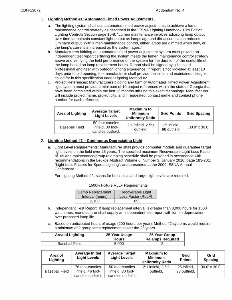
CDH-13072 Addendum No. 4
1. Lighting Method #1: Automated Timed Power Adjustments: a. The lighting system shall use automated timed power adjustments to achieve a lumen
maintenance control strategy as described in the IESNA Lighting Handbook 10th Edition, Lighting Controls Section page 16-8: "Lumen maintenance involves adjusting lamp output over time to maintain constant light output as lamps age and dirt accumulation reduces luminaire output. With lumen maintenance control, either lamps are dimmed when new, or the lamp's current is increased as the system ages."
b. Manufacturers bidding an automated timed power adjustment system must provide an independent test report certifying the system meets the lumen maintenance control strategy above and verifying the field performance of the system for the duration of the useful life of the lamp based on lamp replacement hours. Report shall be signed by a licensed professional engineer with outdoor lighting experience. If report is not provided at least 10 days prior to bid opening, the manufacturer shall provide the initial and maintained designs called for in this specification under Lighting Method #2.
c. Project References: Manufacturers bidding any form of Automated Timed Power Adjustment light system must provide a minimum of 10 project references within the state of Georgia that have been completed within the last 12 months utilizing this exact technology. Manufacturer will include project name, project city, and if requested, contact name and contact phone number for each reference.
Area of Lighting Average Target Light Levels
Maximum to Minimum
Uniformity Ratio Grid Points Grid Spacing
Baseball Field 50 foot-candles infield, 30 foot-
candles outfield.
2:1 infield, 2.5:1 outfield.
25 infield, 98 outfield. 30.0’ x 30.0’
2. Lighting Method #2 – Continuous Depreciating Light a. Light Level Requirements: Manufacturer shall provide computer models and guarantee target
light levels on the field over 25 years. The specified maximum Recoverable Light Loss Factor of .69 and maintenance/group relamping schedule shall be provided in accordance with recommendations in the Leukos Abstract Volume 6, Number 3, January 2010, page 183-201: “Light Loss Factors for Sports Lighting”, and presented at the 2009 IESNA Annual Conference.
For Lighting Method #2, scans for both initial and target light levels are required.
1500w Fixture RLLF Requirements
b. Independent Test Report: If lamp replacement interval is greater than 3,000 hours for 1500 watt lamps, manufacturer shall supply an independent test report with lumen depreciation over proposed lamp life.
c. Based on anticipated hours of usage (200 hours per year), Method #2 systems would require a minimum of 2 group lamp replacements over the 25 years.
Area of Lighting 25 Year Usage Hours
25 Year Group Relamps Required
Baseball Field 5,000 2
Area of Lighting
Average Initial Light Levels
Average Target Light Levels
Maximum to Minimum
Uniformity Ratio Grid
Points Grid
Spacing
Baseball Field 76 foot-candles infield, 46 foot-
candles outfield.
50 foot-candles infield, 30 foot-
candles outfield.
2:1 infield, 2.5:1 outfield.
25 infield, 98 outfield.
30.0’ x 30.0’
Lamp Replacement Interval (hours)
Recoverable Light Loss Factor (RLLF)
2,100 .69
CDH-13072 Addendum No. 4
d. Revised Electrical Distribution: Manufacturer shall provide revised electrical distribution plans to include changes to service entrance, panel, and wire sizing if increased power is required which exceeds specified design loads.
1.3 LIFE CYCLE COSTS
Manufacturer shall submit 25-year life cycle cost calculation as outlined in the required submittal information. If lamp replacement interval is greater than 3000 hours, manufacturer shall supply an independent test report with applicable recoverable light loss factor, initial, and end of life lumens.
Lamp replacement schedule per charts below:
Lighting Method 1 Lamp Replacement Lighting Method 2 Lamp Replacement
5,000 hour intervals 2,100 hour intervals
PART 2 – PRODUCT
2.1 SPORTS LIGHTING SYSTEM CONSTRUCTION
A. Manufacturing Requirements: All components shall be designed and manufactured as a system. All luminaires, wire harnesses, ballast and other enclosures shall be factory assembled, aimed, wired and tested.
B. Durability: All exposed components shall be constructed of corrosion resistant material and/or coated to help prevent corrosion. All exposed carbon steel shall be hot dip galvanized per ASTM A123. All exposed aluminum shall be powder coated with high performance polyester or anodized. All exterior reflective inserts shall be anodized, coated, and protected from direct environmental exposure to prevent reflective degradation or corrosion. All exposed hardware and fasteners shall be stainless steel of 18-8 grade or better, passivated and coated with aluminum-based thermosetting epoxy resin for protection against corrosion and stress corrosion cracking. Structural fasteners may be carbon steel and galvanized meeting ASTM A153 and ISO/EN 1461 (for hot dipped galvanizing), or ASTM B695 (for mechanical galvanizing). All wiring shall be enclosed within the crossarms, pole, or electrical components enclosure.
C. System Description: Lighting system shall consist of the following: 1. Galvanized steel poles and crossarm assembly. Optional Concrete pole with a minimum of
8,000 psi and concrete backfill provided will be an acceptable alternative provided building code, wind speed and foundation designs per specifications are adhered to.
2. Non-approved pole technology. Square static cast poles will not be accepted. Direct bury steel poles which utilize the extended portion of the steel shaft for their foundation will not be accepted due to potential for internal and external corrosive reaction to the soils and long term performance concerns.
3. Pre-stressed concrete base embedded in concrete backfill allowed to cure for 12-24 hours before pole stress is applied. Alternate may be an anchor bolt foundation designed such that the steel pole and any exposed steel portion of the foundation is located a minimum of 18 inches above final grade. The concrete for anchor bolt foundations shall be allowed to cure for a minimum of 28 days before the pole stress is applied.
4. All luminaires shall be constructed with a die-cast aluminum housing or external hail shroud to protect the luminaire reflector system.
5. Manufacturer will remote all ballasts and supporting electrical equipment in aluminum enclosures mounted approximately 10’ above grade. The enclosures shall be touch-safe and include ballast, capacitor and fusing with indicator lights on fuses to notify when a fuse is to be replaced for each luminaire. Safety disconnect per circuit for each pole structure will be located in the enclosure. Integral ballast fixtures will not be accepted.
6. Wire harness complete with an abrasion protection sleeve, strain relief and plug-in connections for fast, trouble-free installation.
7. All luminaires, visors, and crossarm assemblies shall withstand <Wind Speed> mph winds and maintain luminaire aiming alignment
8. Controls and Monitoring Cabinet to provide on-off control and monitoring of the lighting system constructed of NEMA Type 4 aluminum. Communication method shall be provided by manufacturer. Cabinet shall contain custom configured contactor modules for 30, 60, and 100
CDH-13072 Addendum No. 4
amps, labeled to match field diagrams and electrical design. Manual Off-On-Auto selector switches shall be provided.
9. Lightning Protection: Contractor shall provide integrated lightning grounding via concrete encased electrode grounding system as defined by NFPA 780 and be UL Listed per UL 96 and UL 96A. If grounding is not integrated into the structure, the Manufacturer shall supply grounding electrodes, copper down conductors and exothermic weld kits. Electrodes and conductors shall be sized as required by NFPA 780. The grounding electrode shall be not less than 5/8 inch diameter and 8 feet long, with a minimum of 10 feet embedment. Grounding electrode shall be connected to the structure by a grounding electrode conductor with a minimum size of 2 AWG for poles with 75 feet mounting height or less, and 2/0 AWG for poles with more than 75 feet mounting height.
D. Safety: All system components shall be UL listed for the appropriate application.
2.2 ELECTRICAL
A. Electric Power Requirements for the Sports Lighting Equipment: 1. Electric power: 480 Volt, 3 Phase 2. Maximum total voltage drop: Voltage drop to the disconnect switch located on the poles shall
not exceed three percent of the rated voltage.
B. Energy Consumption: The average kW consumption for the field lighting system shall be 62.6 kW for metal halide fixtures in Lighting Method 1. Lighting Method 2 kW will be defined in Life Cycle calculation chart (1.4) using a RLLF of .69.
C. Revised Electrical Distribution: Manufacturer shall provide, at their cost, revised electrical distribution plans to include changes to service entrance, panel, and wire sizing if using Lighting Method 2.
2.3 STRUCTURAL PARAMETERS
A. Mounting Heights: To ensure proper aiming angles for reduced glare and to provide better playability, the minimum pole mounting heights from the playing field surface shall be as noted in Section 1.2.B. Higher mounting heights may be required based on photometric performance of manufacturer’s luminaires to meet spill and glare requirements.
B. Wind Loads: Wind loads shall be based on the 2009 International Building Code. Wind loads to be calculated using ASCE 7-05, a design wind speed of 90MPH, exposure category C.
C. Pole Structural Design: The stress analysis and safety factor of the poles shall conform to 2009 AASHTO Standard Specification for Structural Supports for Highway Signs, Luminaires, and Traffic Signals (LTS-5).
D. Foundation Design: The foundation design shall be based on soil parameters as outlined in the geotechnical report. If a geotechnical report is unavailable, the foundation design shall be based on soils that meet or exceed those of a Class 5 material as defined by 2009 IBC Table 1806.2.
2.4 CONTROLS AND MONITORING
A. Remote Monitoring System: System shall monitor lighting performance and notify manufacturer if individual luminaire outage is detected so that appropriate maintenance can be scheduled. The controller shall determine switch position (Manual or Auto) and contactor status (open or closed)
B. Remote Lighting Control System: System shall allow owner and users with a security code to schedule on/off system operation via a web site, phone, fax or email up to ten years in advance. Manufacturer shall provide and maintain a two-way TCP/IP communication link. Trained staff shall be available 24/7 to provide scheduling support and assist with reporting needs.
The owner may assign various security levels to schedulers by function and/or fields. This function must be flexible to allow a range of privileges such as full scheduling capabilities for all fields, to only having permission to execute “early off” commands by phone. Scheduling tool shall be capable of setting curfew limits.
Controller shall accept and store 7-day schedules, be protected against memory loss during power outages, and shall reboot once power is regained and execute any commands that would have occurred during outage.
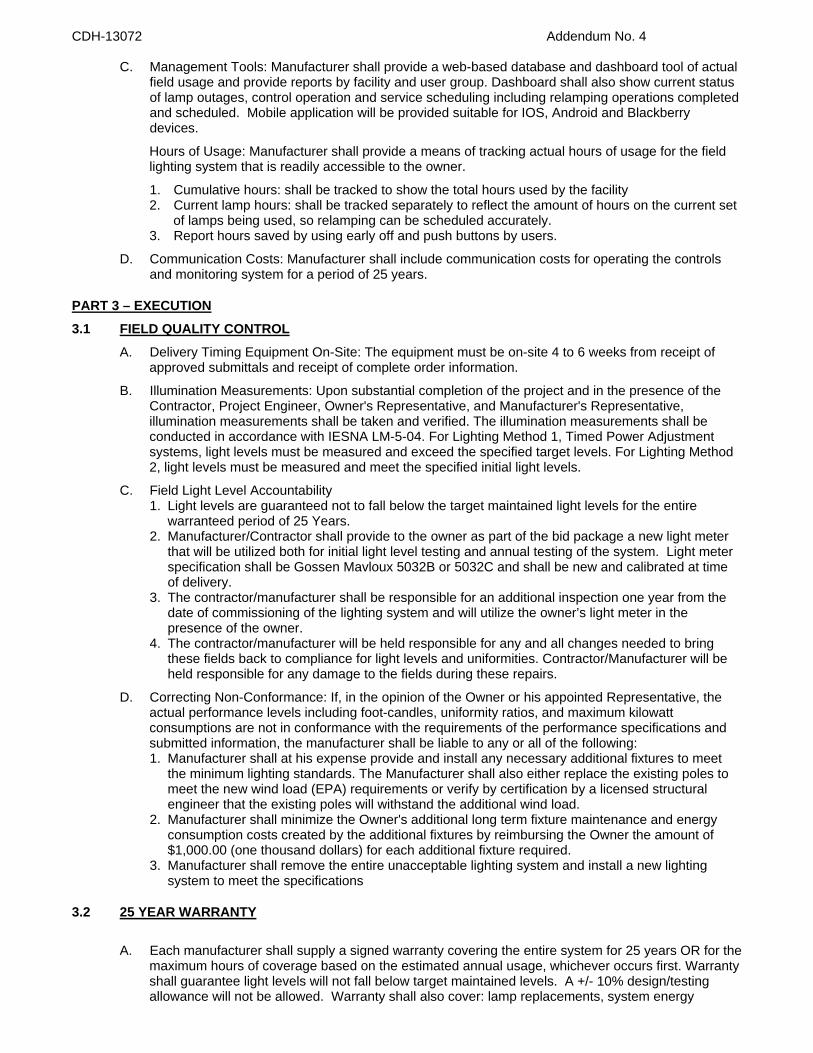
CDH-13072 Addendum No. 4
C. Management Tools: Manufacturer shall provide a web-based database and dashboard tool of actual field usage and provide reports by facility and user group. Dashboard shall also show current status of lamp outages, control operation and service scheduling including relamping operations completed and scheduled. Mobile application will be provided suitable for IOS, Android and Blackberry devices.
Hours of Usage: Manufacturer shall provide a means of tracking actual hours of usage for the field lighting system that is readily accessible to the owner.
1. Cumulative hours: shall be tracked to show the total hours used by the facility 2. Current lamp hours: shall be tracked separately to reflect the amount of hours on the current set
of lamps being used, so relamping can be scheduled accurately. 3. Report hours saved by using early off and push buttons by users.
D. Communication Costs: Manufacturer shall include communication costs for operating the controls and monitoring system for a period of 25 years.
PART 3 – EXECUTION
3.1 FIELD QUALITY CONTROL A. Delivery Timing Equipment On-Site: The equipment must be on-site 4 to 6 weeks from receipt of
approved submittals and receipt of complete order information.
B. Illumination Measurements: Upon substantial completion of the project and in the presence of the Contractor, Project Engineer, Owner's Representative, and Manufacturer's Representative, illumination measurements shall be taken and verified. The illumination measurements shall be conducted in accordance with IESNA LM-5-04. For Lighting Method 1, Timed Power Adjustment systems, light levels must be measured and exceed the specified target levels. For Lighting Method 2, light levels must be measured and meet the specified initial light levels.
C. Field Light Level Accountability 1. Light levels are guaranteed not to fall below the target maintained light levels for the entire
warranteed period of 25 Years. 2. Manufacturer/Contractor shall provide to the owner as part of the bid package a new light meter
that will be utilized both for initial light level testing and annual testing of the system. Light meter specification shall be Gossen Mavloux 5032B or 5032C and shall be new and calibrated at time of delivery.
3. The contractor/manufacturer shall be responsible for an additional inspection one year from the date of commissioning of the lighting system and will utilize the owner’s light meter in the presence of the owner.
4. The contractor/manufacturer will be held responsible for any and all changes needed to bring these fields back to compliance for light levels and uniformities. Contractor/Manufacturer will be held responsible for any damage to the fields during these repairs.
D. Correcting Non-Conformance: If, in the opinion of the Owner or his appointed Representative, the actual performance levels including foot-candles, uniformity ratios, and maximum kilowatt consumptions are not in conformance with the requirements of the performance specifications and submitted information, the manufacturer shall be liable to any or all of the following: 1. Manufacturer shall at his expense provide and install any necessary additional fixtures to meet
the minimum lighting standards. The Manufacturer shall also either replace the existing poles to meet the new wind load (EPA) requirements or verify by certification by a licensed structural engineer that the existing poles will withstand the additional wind load.
2. Manufacturer shall minimize the Owner's additional long term fixture maintenance and energy consumption costs created by the additional fixtures by reimbursing the Owner the amount of $1,000.00 (one thousand dollars) for each additional fixture required.
3. Manufacturer shall remove the entire unacceptable lighting system and install a new lighting system to meet the specifications
3.2 25 YEAR WARRANTY
A. Each manufacturer shall supply a signed warranty covering the entire system for 25 years OR for the maximum hours of coverage based on the estimated annual usage, whichever occurs first. Warranty shall guarantee light levels will not fall below target maintained levels. A +/- 10% design/testing allowance will not be allowed. Warranty shall also cover: lamp replacements, system energy
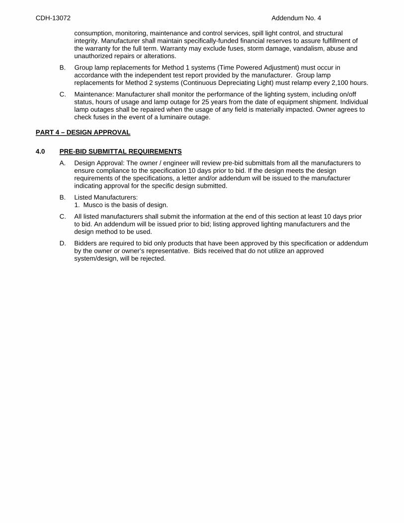
CDH-13072 Addendum No. 4
consumption, monitoring, maintenance and control services, spill light control, and structural integrity. Manufacturer shall maintain specifically-funded financial reserves to assure fulfillment of the warranty for the full term. Warranty may exclude fuses, storm damage, vandalism, abuse and unauthorized repairs or alterations.
B. Group lamp replacements for Method 1 systems (Time Powered Adjustment) must occur in accordance with the independent test report provided by the manufacturer. Group lamp replacements for Method 2 systems (Continuous Depreciating Light) must relamp every 2,100 hours.
C. Maintenance: Manufacturer shall monitor the performance of the lighting system, including on/off status, hours of usage and lamp outage for 25 years from the date of equipment shipment. Individual lamp outages shall be repaired when the usage of any field is materially impacted. Owner agrees to check fuses in the event of a luminaire outage.
PART 4 – DESIGN APPROVAL
4.0 PRE-BID SUBMITTAL REQUIREMENTS
A. Design Approval: The owner / engineer will review pre-bid submittals from all the manufacturers to ensure compliance to the specification 10 days prior to bid. If the design meets the design requirements of the specifications, a letter and/or addendum will be issued to the manufacturer indicating approval for the specific design submitted.
B. Listed Manufacturers: 1. Musco is the basis of design.
C. All listed manufacturers shall submit the information at the end of this section at least 10 days prior to bid. An addendum will be issued prior to bid; listing approved lighting manufacturers and the design method to be used.
D. Bidders are required to bid only products that have been approved by this specification or addendum by the owner or owner’s representative. Bids received that do not utilize an approved system/design, will be rejected.
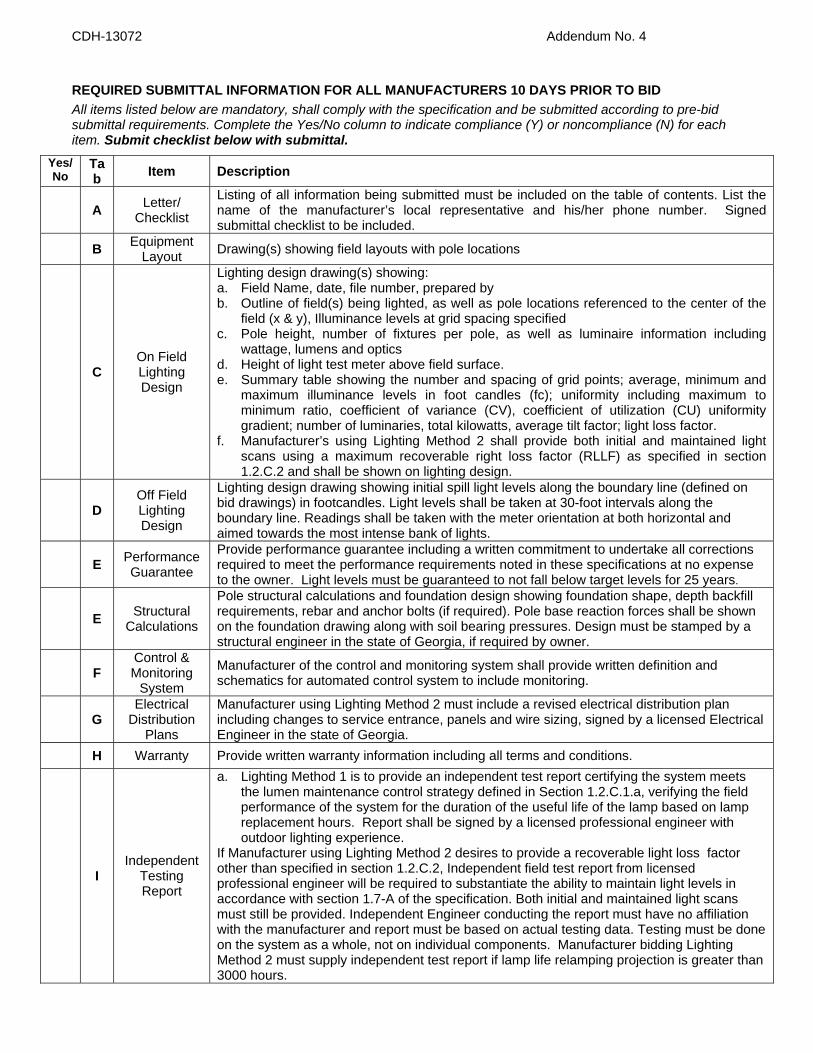
CDH-13072 Addendum No. 4
REQUIRED SUBMITTAL INFORMATION FOR ALL MANUFACTURERS 10 DAYS PRIOR TO BID All items listed below are mandatory, shall comply with the specification and be submitted according to pre-bid submittal requirements. Complete the Yes/No column to indicate compliance (Y) or noncompliance (N) for each item. Submit checklist below with submittal.
Yes/ No
Tab Item Description
A Letter/
Checklist
Listing of all information being submitted must be included on the table of contents. List the name of the manufacturer’s local representative and his/her phone number. Signed submittal checklist to be included.
B Equipment Layout Drawing(s) showing field layouts with pole locations
C On Field Lighting Design
Lighting design drawing(s) showing: a. Field Name, date, file number, prepared by b. Outline of field(s) being lighted, as well as pole locations referenced to the center of the
field (x & y), Illuminance levels at grid spacing specified c. Pole height, number of fixtures per pole, as well as luminaire information including
wattage, lumens and optics d. Height of light test meter above field surface. e. Summary table showing the number and spacing of grid points; average, minimum and
maximum illuminance levels in foot candles (fc); uniformity including maximum to minimum ratio, coefficient of variance (CV), coefficient of utilization (CU) uniformity gradient; number of luminaries, total kilowatts, average tilt factor; light loss factor.
f. Manufacturer’s using Lighting Method 2 shall provide both initial and maintained light scans using a maximum recoverable right loss factor (RLLF) as specified in section 1.2.C.2 and shall be shown on lighting design.
D
Off Field Lighting Design
Lighting design drawing showing initial spill light levels along the boundary line (defined on bid drawings) in footcandles. Light levels shall be taken at 30-foot intervals along the boundary line. Readings shall be taken with the meter orientation at both horizontal and aimed towards the most intense bank of lights.
E Performance
Guarantee
Provide performance guarantee including a written commitment to undertake all corrections required to meet the performance requirements noted in these specifications at no expense to the owner. Light levels must be guaranteed to not fall below target levels for 25 years.
E Structural
Calculations
Pole structural calculations and foundation design showing foundation shape, depth backfill requirements, rebar and anchor bolts (if required). Pole base reaction forces shall be shown on the foundation drawing along with soil bearing pressures. Design must be stamped by a structural engineer in the state of Georgia, if required by owner.
F
Control & Monitoring
System
Manufacturer of the control and monitoring system shall provide written definition and schematics for automated control system to include monitoring.
G
Electrical Distribution
Plans
Manufacturer using Lighting Method 2 must include a revised electrical distribution plan including changes to service entrance, panels and wire sizing, signed by a licensed Electrical Engineer in the state of Georgia.
H Warranty Provide written warranty information including all terms and conditions.
I Independent
Testing Report
a. Lighting Method 1 is to provide an independent test report certifying the system meets the lumen maintenance control strategy defined in Section 1.2.C.1.a, verifying the field performance of the system for the duration of the useful life of the lamp based on lamp replacement hours. Report shall be signed by a licensed professional engineer with outdoor lighting experience.
If Manufacturer using Lighting Method 2 desires to provide a recoverable light loss factor other than specified in section 1.2.C.2, Independent field test report from licensed professional engineer will be required to substantiate the ability to maintain light levels in accordance with section 1.7-A of the specification. Both initial and maintained light scans must still be provided. Independent Engineer conducting the report must have no affiliation with the manufacturer and report must be based on actual testing data. Testing must be done on the system as a whole, not on individual components. Manufacturer bidding Lighting Method 2 must supply independent test report if lamp life relamping projection is greater than 3000 hours.
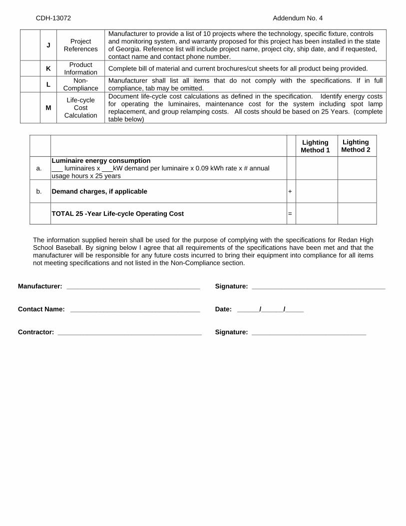
CDH-13072 Addendum No. 4
J Project
References
Manufacturer to provide a list of 10 projects where the technology, specific fixture, controls and monitoring system, and warranty proposed for this project has been installed in the state of Georgia. Reference list will include project name, project city, ship date, and if requested, contact name and contact phone number.
K Product Information Complete bill of material and current brochures/cut sheets for all product being provided.
L Non-Compliance
Manufacturer shall list all items that do not comply with the specifications. If in full compliance, tab may be omitted.
M
Life-cycle Cost
Calculation
Document life-cycle cost calculations as defined in the specification. Identify energy costs for operating the luminaires, maintenance cost for the system including spot lamp replacement, and group relamping costs. All costs should be based on 25 Years. (complete table below)
Lighting
Method 1 Lighting Method 2
a. Luminaire energy consumption ___ luminaires x ___kW demand per luminaire x 0.09 kWh rate x # annual usage hours x 25 years
b. Demand charges, if applicable +
TOTAL 25 -Year Life-cycle Operating Cost =
The information supplied herein shall be used for the purpose of complying with the specifications for Redan High School Baseball. By signing below I agree that all requirements of the specifications have been met and that the manufacturer will be responsible for any future costs incurred to bring their equipment into compliance for all items not meeting specifications and not listed in the Non-Compliance section.
Manufacturer: ____________________________________ Signature: ____________________________________ Contact Name: ___________________________________ Date: ______/______/_____ Contractor: _______________________________________ Signature: _______________________________

CONSTRUCTION SPECIFICATIONS, DEFINITIONS AND PRODUCT DESCRIPTIONS
TOPSOIL Friable surface soil, if included, which is reasonably free of sub-soil, rocks, stones, sticks, and other debris over two inches (2”) in diameter and without weeds, roots, and other objectionable materials.
Sub-surface soil Soil directly below the top soil being existing in soil and/or properly
compacted imported soil, both being stable as a supporting medium in acceptable as a part of a root zone for sports field construction.
Sand United States Golf Association (USGA) green sand or sand meeting the
USGA specs per particle size analysis. Infield Material Material consisting of approximately eight percent (80%) sand and
twenty percent (20%) clay accurately blended off-site. Soil Conditioner A sports field conditioner, not crushed aggregate lick brick dust and
vitrified clay, to incorporate into the infield material to prevent compaction and improve moisture absorption.
Lime Dolomitic lime, stone ground to meet agricultural standards containing a
minimum of eighty five percent (85%) carbonate. Fertilizer A commercial mixed grade fertilizer including five percent (5%) of
nitrogen, ten percent (10%) phosphorus, and fifteen percent (15%) of potassium.
Root Zone Mix The properly blended combination of sand, silt, clay, and organic
material. Sand should be USGA ranging from eighty percent to ninety percent (80% - 90%) of this mixture, variable based on the percolation required.
Warning Track 3” of 8910 granite product material installed adjacent to all fencing and
walls as designated. A minimum width of ten feet (10’) adjacent to outfield fencing.
Sod Certified tifsport hybrid Bermuda grass produced under the rules and
regulations of the Georgia crop improvement associated, Inc. Sod shall be harvested from veraciously growing properly fertilized harvested fields in 30” width rolls.
Warrantied Sod The specific areas of sod harvested and installed during the dormant
season that later does not demonstrate reasonable regrowth of stolens to sufficiently reestablish an acceptable playing surface therefore, is subsequently replaced by the contactor at no cost to the owner.
Owners Rep Party or parties who are the key contact persons on behalf of the owner
Laser Grading Laser grading shall include the use of land lever that grading is equipped with a laser controlled hydraulic system that automatically raises and lowers the implement. This implement shall be towed by an agricultural type tractor to reduce compaction (for softball fields a cone laser is mandatory). Laser grading shall be a multiple step process beginning with the subgrade and continuing with each layer of amendments including the subgrade, topsoil layer, sand layer, and the final root zone. Each of these four (4) individual layers will require a laser grading process and will meet the following degrees of variation to desired slopes and elevations: the subgrade +/- one half inch (1/2”), the topsoil layer +/- one half inch (1/2’), the sand layer one half inch (1/2”), and the finished surface grade +/- one fourth inch (1/4”)
Containment Native soil shaped to surround and contain sand, root zone material,
infield material, and/or warning track material from erosion, depth should be the same as material to be contained and at the same slope of a minimum 10 width outside of erodible material.