Embed Size (px)
Citation preview

07-98 938989/0
NUM1020/1040/1050/1060 T
Additif au manuel 938820/5Addition to manual 938820/5
0100938989/0
2 938989/0
Despite the care taken in the preparation of this document, NUM cannot guarantee the accuracy of the information it contains and cannot be
held responsible for any errors therein, nor for any damage which might result from the use or application of the document.
The physical, technical and functional characteristics of the hardware and software products and the services described in this document are
subject to modification and cannot under any circumstances be regarded as contractual.
The programming examples described in this manual are intended for guidance only. They must be specially adapted before they can be used
in programs with an industrial application, according to the automated system used and the safety levels required.
© Copyright NUM 1998.
All rights reserved. No part of this manual may be copied or reproduced in any form or by any means whatsoever, including photographic or
magnetic processes. The transcription on an electronic machine of all or part of the contents is forbidden.
© Copyright NUM 1998 software CNC NUM 1000 family.
This software is the property of NUM. Each memorized copy of this software sold confers upon the purchaser a non-exclusive licence strictly
limited to the use of the said copy. No copy or other form of duplication of this product is authorized.

938989/0 3
1 Evolutions taraudage rigide 51.1 Rappel : Cycle de taraudage rigide : G84 51.2 Programmation du cycle 51.3 Arrêt du cycle de taraudage rigide 51.4 Autres évolutions et corrections 6
2 Détaraudage rigide 72.1 Description fonctionnelle 72.1.1 Utilisation 72.1.2 Programmation du cycle 72.1.3 Erreurs détectables 82.1.4 Exécution du cycle de détaraudage rigide 82.1.5 Conditions particulières pour sortir les outils
"à vue" 8
3 Evolution synchronisation des broches 93.1 Description fonctionnelle du logiciel 93.1.1 Accélération fonction vitesse 93.2 Synchronisation de broches avec maître piloté
en vitesse 103.2.1 Correcteur à action intégrale 103.2.2 Correcteur à avance de phase variable 113.3 Interface Homme - Machine 123.4 Principe d'utilisation du produit logiciel 133.4.1 Procédure de réglage 133.4.2 Programmation de la synchronisation de
broches 133.5 Liste des paramètres E relatifs aux broches 16
4 Reprise de filetage 184.1 Généralités 184.2 Programmation 184.3 Contraintes 194.4 Intégration de la fonction G38+ dans le cycle
G33 194.4.1 Syntaxe de la reprise _filetage dans l'appel du
cycle G33 19
5 Evolution et mises à jour diverses 205.1 Création des fichiers CN 205.2 Chapitre 6.5 "Affichage d'un message avec
réponse de l'opérateur" 205.3 Cycle de prise d'origine automatique 205.3.1 Mode POM 205.3.2 Appel par fonction G159 : Mode CONT (ou IMD) 225.3.3 Axes synchronisés par paramètres machine 235.3.4 Commutation broche/axe C en DISC NT 23
Additif au manuel de Programmation T - 938820/5

4 938989/0
Addition to T Programming manual - 938820/5
1 Changes to Rigid Tapping 251.1 Review: Rigid Tapping Cycle: G84 251.2 Programming the Cycle 251.3 Stopping the Rigid Tapping Cycle 251.4 Other Changes and Corrections 26
2 Rigid Tap Removal 272.1 Functional Description 272.1.1 Use 272.1.2 Programming the Cycle 272.1.3 Detectable Errors 282.1.4 Execution of the Rigid Tap Removal Cycle 282.1.5 Particular Conditions for Tap Removal on Sight 28
3 Change in Spindle Synchronisation 293.1 Functional Description of the Software 293.1.1 Speed-Dependent Acceleration 293.2 Spindle Synchronisation with Master Spindle
Speed Control 303.2.1 Corrector with Integral Action 303.2.2 Corrector with Variable Phase Lead 313.3 Man/Machine Interface 323.4 Principle of Use of the Software Product 333.4.1 Setting Procedure 333.4.2 Programming Spindle Synchronisation 333.5 List of Parameters E Relative to Spindles 36
4 Resumption of Thread Cutting 384.1 General 384.2 Programming 384.3 Constraints 394.4 Inclusion of function G38+ in Cycle G33 394.4.1 Syntax of Resumed Thread Cutting Included
in the Call to Cycle G33 39
5 Miscellaneous Changes and Updates 405.1 Creation of CNC Files 405.2 Section 6.5, Message display with wait
operator response 405.3 Automatic Homing Cycle 405.3.1 Homing Mode 405.3.2 Call by Function G159: AUTO (or MDI) Mode 425.3.3 Axes Synchronised by Machine Parameters 435.3.4 Spindle/C-axis switching in DISC NT 43
938989/0 5
Additif au manuel de programmation T - 938820/5
1 Evolutions taraudage rigide
1.1 Rappel : Cycle de taraudage rigide : G84
Le cycle permet d'asservir l'avance de l'outil à la rotation de la broche. La vitesse d'avance est calculée automatiquementselon la vitesse de la broche et le pas programmés.
Le cycle permet la programmation de taraudage suivant les axes X ou Z. La modulation des vitesses par potentiomètren'est pas inhibée pendant l'exécution du cycle. Le potentiomètre "Broche" est toujours actif ; le potentiomètre "Avance"est sans effet pendant le taraudage proprement dit ; il est actif durant les divers autres positionnements.
1.2 Programmation du cycle
Le cycle G84 permet désormais de programmer ou non la fonction M05
Par exemple : G84 Z-200 K1.25 EK2.5 M5
Si la fonction M05 est programmée dans le cycle de taraudage rigide, la broche sera arrêtée en fin de taraudage.
Si la fonction M05 n'est pas programmée dans le cycle de taraudage rigide, la broche sera remise en rotation dans lesens initial.
Les fonctions G84 peuvent désormais être programmées dans l'un des 8 groupes et utiliser l'une des 4 broches si ellessont conformes.
Le reste du cycle de taraudage rigide est sans changement.
Exécution du cycle de taraudage rigide
Ce cycle est réalisé dans les mêmes conditions que précédemment.
La broche doit être pilotée par le groupe où est programmé le cycle.
En fin de G84, une fois la cote EH atteinte (retour à la cote du plan d'attaque sur l'axe d'usinage), si M5 est programméedans le cycle, la broche sera mise dans l'état M5.
En fin de taraudage, Z est en haut du trou :
s'il y a inversion de broche
La broche ralentit suivant E9033b (initialisé par P32 N48) jusqu'à l'arrêt... puis s'inverse.
Les mouvements d'axes commencent dès que la broche tourne dans le bon sens.
S'il y a arrêt de broche - M5 Programmé
La broche ralentit suivant E9033b jusqu'à l'arrêt de la broche.
Les mouvements des axes se font pendant la décélération broche.
1.3 Arrêt du cycle de taraudage rigideSi "Stop_broche" d'une broche, en cours de taraudage rigide, passe à 1 (%W22.i =1 avec i ∈ [0..3]), celle-ci est arrêtéeet par conséquent l'axe d'usinage est synchronisé.
Si "Stop_broche" d'une broche, en cours de taraudage rigide, repasse à 0 (%W22.i =0 avec i ∈ [0..3]), la broche estrelancée et le taraudage rigide reprend. La manipulation du "Stop_broche" est réservée au cas d'urgence.
A l'arrêt de la broche, RAZ_CN peut alors être exécuté et le taraudage rigide sera abandonné.
Il est possible d'exécuter n'importe quelle fonction disponible dont un taraudage rigide en mode CONT ou IMD.

6 938989/0
1.4 Autres évolutions et corrections
La nouvelle version du G84 permet d'effectuer un taraudage rigide sur les systèmes au 1/10ème de µm.
Les fonctions actionnant ou invalidant des transformations géométriques (inch/métrique, facteur d'échelle, PREF/DEC,etc ...) actives lors d'un cycle G84 (taraudage rigide) sont prises en compte dans les conditions suivantes :- les cotes et le pas sont comptés dans l'unité active en pouce (inch) ou mm en G70 ou G71.- le facteur d'échelle s'il est valide s'applique à toutes les cotes programmées dans le cycle G84 (X..Z, ER et EH), mais
il ne s'applique pas au pas (K) et à (EK).- la fonction miroir, sur l'axe outil, est incompatible avec G84 (taraudage rigide).
Ce comportement est aussi celui de la fonction G39+ (détaraudage rigide).
Jusqu'à la version L du logiciel, le taraudage rigide (G84) en pouce (inch) ou en 1/10ème de µm entraînait les problèmessuivants :- lorsque l'unité était définie en pouce (inch), le pas K était divisé par 2,54,- lors du détaraudage, la vitesse de broche était aussi divisée par 2,54,- le rapport EK était affiché sur page INFO multiplié par 10,- en 1/10 ème de µm : La vitesse de broche au détaraudage pouvait être limitée : par exemple : S60 G84 K1 EK2 ...
provoquait un détaraudage à S100 (au lieu de S120).

938989/0 7
Additif au manuel de programmation T - 938820/5
2 Détaraudage rigide
2.1 Description fonctionnelle
2.1.1 Utilisation
Circonstance de mise en œuvre : un incident est survenu en cours de taraudage rigide. L'opérateur a dû, pour une raisonimpérieuse, interrompre le taraudage rigide en cours et éventuellement couper la tension sur la CN : l'outil reste prisonnierde la matière.
La fonctionnalité de détaraudage rigide permet désormais de commander plus aisément la sortie de l'outil hors de lamatière ; y compris si la POM n'a pas pu être réalisée et si le plan incliné est valide.
2.1.2 Programmation du cycle
Syntaxe
[M64 à M66] G39+ M3/M4 [M40 à M45] S.. K.. Z..
avec :
M64 M66 Si nécessaire fonctions permettant au groupe de commander la broche.
G39+ Cycle de détaraudage rigide qui appelle 4 paramètres obligatoireset un paramètre optionnel programmés immédiatement derrière la fonction.
M3 ou M4 Sens de rotation de la broche.
M40 à M45 Choix de la gamme (Paramètre optionnel).
S.. Vitesse de rotation de la broche.
K.. Valeur du pas en mm.
Z.. Axe et longueur signée du dégagement (en mm et en relatif).Les axes U à Z peuvent être programmés s'ils existent.
Particularités
Les arguments du cycles peuvent être remplacés par des paramètres E ou des variables L.
Exemple 1 :G39+ M3 M41 S200 K1.2 W10
Exemple 2 : si E80000 = 3 et E80001 = 42G39+ ME80000 ME80001 SL0 KL1 Z-10
Les fonctions actionnant ou invalidant des transformations géométriques (inch/métrique, facteur d'échelle, PREF/DEC,etc...) actives lors du G39+ sont prises en compte dans les conditions suivantes :- les cotes et le pas sont comptés dans l'unité active pouce (inch) ou mm avec G70 ou G71,- le facteur d'échelle, s'il est valide, s'applique à la cote concernée, mais il ne s'applique pas au pas (K),- la fonction miroir est incompatible avec G39+.
Ce comportement est identique à celui de la fonction G84 ( taraudage rigide).
On notera :- que le cycle G39+ force l'utilisation de la broche en G97.- que l'outil ne devant pas être programmé et le déplacement étant effectué en relatif, la cohérence de la direction d'outil
n'est pas vérifiée.

8 938989/0
2.1.3 Erreurs détectables
Erreur 4 : si l'option 20 est absente
Erreur 2 : si l'un des 4 arguments obligatoires (M3/M4 ou S ou K ou Z) n'a pas été programmé
si un autre argument a été programmé
si une fonction M différente de [M3/M4 - M40 à M45]
si S est trop grand (>65536)
si K est négatif ou nul
Erreur 1 : si l'axe programmé n'existe pas
si plusieurs axes sont programmés ou un même axe plusieurs fois
si M3/M4 ou M40 à M45 sont programmés deux fois
si miroir est actif sur l'axe de taraudage
si la broche n'est pas en état M5
Erreur 39 : si S n'est pas compatible avec la gamme programmée
si on doit faire une recherche de gamme automatique alors que cela n'est pas autorisé [gamma nonprogrammée et bit 7 de P7 N0 à 1]
2.1.4 Exécution du cycle de détaraudage rigide
Ce cycle peut être réalisé même si la POM sur l'axe et/ou la broche n'a pas été faite.
Le plan incliné peut être actif.
La broche doit être pilotée par le groupe où est programmé le cycle.
Elle est en début de cycle dans l'état M5.
Pour mise à l'échelle de la consigne de broche, on doit retrouver la gamme qui était enclenchée lors du taraudageinterrompu. Si nécessaire, la gamme sera reprogrammée dans le cycle G39+. Si la gamme n'est pas programmée, onfera l'équivalent d'une recherche de gamme automatique : la fonction ne sera pas transmise à l'automate.
On n'exécutera pas les sous-programmes normalement appelés par les fonctions M3/M4 et M40 M45.
En début de cycle, la broche est commandée dans le sens demandé avec la vitesse de broche minimum (P62 N1, N3,N5 ou N7). Puis la vitesse de broche est uniformément accélérée jusqu'à atteindre la vitesse S programmée.
Dès le début du cycle, le mouvement de l'axe Z est asservi à la broche [G38] en minimisant l'erreur de poursuite de façonque le pas soit respecté. On utilise les paramètres du taraudage rigide décrit dans P63.
En fin de cycle, une fois la course atteinte, la broche est arrêtée et retrouve son état initial et on force, par ailleurs eninterne, une fonction M2.
2.1.5 Conditions particulières pour sortir les outils "à vue"
Arrêt_Broche [%W22.0 à 3] est actif et génère une décélération de la broche et de l'axe.
REMARQUE La RAZ est possible si l'axe et la broche sont immobiles.
Comme en taraudage rigide (pendant la phase de détaraudage) :- le potentiomètre d'avance est forcé 100%,- l'ARUS est actif,- le potentiomètre de broche reste actif.

938989/0 9
Additif au manuel de programmation T - 938820/5
3 Evolution synchronisation des brochesA partir de l'indice M, la synchronisation utilise un principe différent dans lequel la broche maître n'est pas asservie enposition mais pilotée en boucle ouverte de vitesse.
3.1 Description fonctionnelle du logiciel
Conventions d'écriture
BM et BE signifient Broche Maître ou Broche Esclave ou Numéro de broche maître ou Numéro de broche esclave.
Le numéro d' une broche est compté de 0 à 3.
Lorsque les broches sont désignées par B, il s'agit indifféremment de la broche maître ou la broche esclave.
Lorsqu'un paramètre E est noté Exxxxx+B, xxxxx+B est le numéro du paramètre.
Exemple : pour la broche esclave d'adresse 1 E94124+BE = E94125.
3.1.1 Accélération fonction vitesse
Afin de coller aux capacités d'accélération réelles de la broche (cf. 3.1), l'utilisateur a la possibilité de choisir uneaccélération variable en fonction de la vitesse.
Les nouveaux paramètres E90370+b et E90380+b permettent de définir la vitesse limite pour le couple maximum etla puissance max., l'unité est le tr/min.
E90370+b = Nbase
E90380+b = Nmax
Lorsque le paramètre E90360+b est supérieur à 0, la gestion de l'accélération en fonction de la vitesse est validée.
La loi est la suivante :SI N< E90370 ALORS accélération = maximum donnée par E90330SI E90370 < N < E90380 ALORS accélération = E90330 * E90370 / NSI N < E90380 ALORS accélération = E90330 * E90370 * E90380 / N2
REMARQUES :- cette fonctionnalité peut être utilisée indépendamment de la synchronisation,- lorsqu'une broche est esclave, il n'y a pas de gestion de l'accélération sur cette broche : La BE
reçoit la consigne de la BM.- lorsque une BM est plus dynamique qu'une BE, il faut régler les paramètres de la BM pour
permettre à la BE de suivre.- aucun contrôle n'est effectué sur la valeur des paramètres E90370 et E 90380.

10 938989/0
3.2 Synchronisation de broches avec maître piloté en vitesse
Schéma général
MAXCNA
MAXGAM
+/-
Correcteur 1
Correcteur à avancede phasevariable
+/-
MAXCNA
MAXGAM
+:- Vitesse BMCorrection vitesse
Vitesse BE
Vitesse BM
K0*F
REFBROE9020x
REFBROE9020x
Mesure BE E9010x
Mesure BM E9010x
Décalage EC...
++
+
+
Gestion vitesse
etaccélération
S
-
3.2.1 Correcteur à action intégrale
L'action intégrale est utilisée pour annuler l'erreur statique. L'erreur statique est l'erreur qui existerait en régime établi avecune consigne de vitesse constante pour BM. Cette erreur se produit car, comme les broches sont pilotées en boucleouverte de vitesse, il existe toujours un écart entre la vitesse demandée et la vitesse réelle. C'est pourquoi, afin deminimiser l'action intégrale (ce qui est bénéfique pour la réponse en dynamique), il faut régler la boucle de vitesse dela BM et de la BE (c'est à dire vitesse réelle = vitesse demandée). Ce réglage se fait en général par le retour tachymètriqueau niveau du variateur, après avoir vérifié les paramètres P46, P47, P48, et P49 (vitesse maximum de la gamme).
Lorsque les deux broches sont liées mécaniquement, il faut figer l'action intégrale pour ne pas cumulerl'éventuelle erreur résiduelle.
Ceci est piloté par le paramètre E98024+BE :SI E98024 = 0 ALORS pas d'action intégraleSI E98024 > 0 ALORS action intégrale avec Ti = E98024 (en ms)SI E98024 < 0 ALORS action intégrale figée
++
1
Ti*p
E98024 > 0
Ti = E98024SE

938989/0 11
Additif au manuel de programmation T - 938820/5
3.2.2 Correcteur à avance de phase variable
Les essais ont montré que lorsque l'on asservit une broche en position, avec le principe utilisé pour un axe (correcteurP avec gain K0 constant), il apparaît une tendance à l'instabilité (pompage) à haute vitesse.
Pref+
-
K0Vref V P1
1 + Tbv(N) * p p
1
.
Ceci est dû au fait que la constante de temps de la boucle de vitesse Tbv(N) croît à haute vitesse.
Pour une bonne stabilité, il faut maintenir le produit K0 * Tbv(N) < 0.5.
Comme Tbv(N) croît avec N, il faudrait donc diminuer K0 quand la vitesse augmente.
Mais alors le temps de réponse à un échelon (de vitesse ou d'erreur de synchronisation) devient prohibitif.
Un correcteur à avance de phase variable K0 1 + Tbv(N) x p1 + Tbv0 x p a été implanté dans la CN. Son rôle est de substituer
une constante de temps fixe Tbv0 à la constante de temps variable Tbv(N). Les essais ont montré son utilité à
vitesse élevée.
La CN calcule la valeur Tbv(N) = f(N) à partir de :- Tbv0,- des paramètres E90370 et E90380
Il n'y a pas de paramètre spécifique pour Tbv0. Tbv0 est déduite du gain K0 (E90320+b)
En effet, dans un système du premier ordre bouclé, la stabilité impose la relation suivante entre le gain et la constantede temps :
1 / 3 < K0 x Tbv0 < 1 / 2 d'ou on déduit Tbv0 ≈ 12 x K0
La loi suivie est :SI N < E90370 ALORS Tbv(N) = Tbv0SI E90370 < N < E90380 ALORS Tbv(N) = Tbv0 x N / E90370SI N > E90380 ALORS Tbv(N) = Tbv0 x N2 / E90370 / E90380
On peut même essayer de réduire cette valeur Tbv0. Pour cela un facteur d'amélioration F est introduit. Le paramètreE90360+BE lorsqu'il est supérieur à UN valide le correcteur à l'avance de phase et sa valeur représente alors le facteur F(l'unité est le millième ex : Lorsque E90360 = 1000, F=1 et la constante de temps visée est Tbv0, lorsque E90360 = 1200,F=1,2 et la constante visée est Tbv0/1,2).

12 938989/0
Réponse du correcteur à un échelon
La réponse du correcteur à un échelon dépend de la vitesse et a la forme suivante :
0 <N1 < N2Tbv(N1) / Tbv0
Tbv(N2) / Tbv0
Remarque concernant les paramètres E90370 et E90380
Les paramètres E90370 et E90380 sont utilisés pour régler l'accélération et la constante de temps. Ceci n'est pas unproblème car :- les deux utilisations sont exclusives : quand ils servent pour calculer la constante de temps , c'est que la broche est
esclave et dans ce cas l'accélération n'est pas calculée et vice & versa,- pour chaque type d'utilisation les valeurs sont liées à la caractéristique couple / vitesse du moteur et sont voisines
de Nbase pour E90370 et de Nmax pour E90380.
3.3 Interface Homme - Machine
L'erreur de synchronisation est visualisable par le paramètre externe E95224+BE

938989/0 13
Additif au manuel de programmation T - 938820/5
3.4 Principe d'utilisation du produit logiciel
3.4.1 Procédure de réglage
Ajuster la boucle de vitesse de chaque broche pour que la vitesse mesurée soit identique à la vitesse programmée.
Agir sur le retour tachymétrique au niveau du variateur en contrôlant la vitesse mesurée affichée dans la page INFOS.
Supprimer les rampes d'accélération sur les variateurs.
Si possible mettre la broche la plus dynamique en esclave.
Régler les plages de vitesse Nbase et Nmax.
Relever les vitesses de rotation de couple max (Nbase) et de puissance max (Nmax) sur la courbe S1 du catalogue dumoteur.
Ramener ces vitesses à la broche si le rapport de transmission moteur / broche n'est pas de 1.
Renseigner les paramètres E90370+B = Nbase et E90380+B = Nmax.
Régler l'accélération maximum du maître et de l'esclave E90330+B
Si le maître est plus dynamique que l'esclave, l'aligner sur l'esclave.
Réglage du PI.
Faire K0 = E90320+BE = 500 Ti = E98024+BE Fboost = E90360+BE = 1000
Faire des échelons de vitesse de 1000 tr/mn. Régler K0 pour avoir une bonne réponse de l'erreur de synchronisation.
Régler Ti = E98024+BE = 500 ms. Puis ajuster pour avoir un dépassement sans oscillation.
Faire des échelons plus importants. Puis des inversions de sens. Vérifier le comportement. Ajuster Nbase et Nmax del'esclave si nécessaire.
Si à vitesse élevée, il y a une oscillation importante de l'erreur de synchro, augmenter Fboost et diminuer Nmax del'esclave.
3.4.2 Programmation de la synchronisation de broches
Choix du maître
La demande de synchronisation d'une broche esclave sur une broche maître se fait dans le programme pièce enchargeant le paramètre E94124+BE avec l'adresse physique de la broche maître (24+BM).
Ex : broches 0 et 1 esclaves , broche 3 maître E94124 = 27, E94125 = 27
La synchronisation est refusée avec l'erreur 94, si le POM n'est pas faite sur la BM et la BE.
Choix de l'état direct ou inverse
Préalablement à la demande de synchronisation, le sens de rotation (M3 ou M4) doit avoir été programmé pour la BMet la BE. Ceci permet de choisir l'état de la synchronisation : si les deux sens sont identiques, la synchronisation estdirecte ; sinon elle est inverse.

14 938989/0
Programmation de l'écart angulaire
Lors de la synchronisation la valeur de la fonction EC donne l'écart demandé entre la position de la broche maître et cellede l'esclave. Position BE =+/- (position BM + EC). EC se programme en degré.
Choix du type de synchronisation
Lors de la demande de synchronisation, si les broches ne sont pas asservies en position, la synchronisation se faitsuivant le principe présenté dans cette note, sinon c'est la synchronisation broches asservies et autorégulation du gainqui est choisie.
Paramètres d'accélération de la broche maître
Préalablement à la demande de synchronisation, les paramètres concernant l'accélération du maître doivent êtrerenseignés :
E90330+BM Accélération max en °/ s2. Par défaut, la valeur spécifiée dans le paramètre P32 est prise en compte
E90370+BM Nbase Vitesse limite de couple max en tr/min
E90380+BM Nmax Vitesse limite de puissance max en tr/min
E90360+BM Validation de l'accélération = f(N) si > 0
On notera que si le BE est moins dynamique que la BM, ce sont les caractéristiques de la BE qu'il faut choisir (sinonla BE ne pourra pas suivre la BM pendant les phases d'accélération).
Paramètres d'asservissement de la broche esclave
Préalablement à la demande de synchronisation, les paramètres de la BE ci-dessous doivent être renseignés :
E90320+BE Gain K0 de la boucle de la position en tr/min/tr
E90370+BE Vitesse limite pour Tbv(N) = Tbv0 (E90370 = Nbase)
E90380+BE Vitesse limite N°2 pour calcul de Tbv(N) (E90380 = Nmax)
E90360+BE Facteur F d'amélioration
E98024+BE Constante de temps de l'action intégrale en ms
Mise en service et hors service de l'action intégrale
L'action intégrale permet d'annuler l'erreur statique. Elle doit être mise en service pendant la phase de synchronisation.Lorsque les deux broches sont liées mécaniquement par la pièce (par exemple : pendant un tronçonnage), il est impératifde figer la correction intégrale à la valeur courante au moment du couplage mécanique.
E98024+BE = 0 Pas d'action intégrale
E98024+BE > 0 Action intégrale avec Ti = E98024+BE (en ms)
E98024+BE < 0 Action intégrale figée

938989/0 15
Additif au manuel de programmation T - 938820/5
Tolérance et erreur de synchronisation
L'erreur de synchronisation (différence des positions mesurées) est lue dans E95224+BE (en UI) ; lorsqu'elle estinférieure à la tolérance chargée dans le paramètre P44 ou programmée dans E90310+BE (en tr/65536), l'informationbroche en position est transmise à l'automate (%R13.B) et le booléen E93524+BE passe en 1.
Exemple de programmation
(SYNCHRO BROCHE PILOTEE EN VITESSE)(MASTER = B1 SLAVE = B2)WHILE E91124=1 DO $FAIRE POM broche 1M64M40M3S50%ENDWWHILE E91125=1 DO $FAIRE POM broche 2M65M40M3S50ENDWE94124=-1 Annuler synchro B1E94125=-1 Annuler synchro B2E91024=0 B1 pilotée en vitesseE91025=0 B2 pilotée en vitesseE90330=20000 Accélération max B1 en °/s2
E90331=20000 Accélération max B2E90370=1500 Nbase Vitesse de couple max B1 en tr/minE90371=1500 Nbase Vitesse de couple max B2E90380=4000 Nmax Vitesse de puissance max B1 en tr/minE90381=4000 Nmax Vitesse de puissance max B2E90321=500 Gain B2 en tr/min/trE98025=500 Ti B2 en msE90360=1 Valide accélération = f[N] sur maîtreE90361=1000 Valide correcteur avance de phase sur esclaveM64 M40 M4 S100 EC0 Lancer B1M65 M40 M4 S100 Lancer B2E94125=24 Synchro B2/B1 broche maîtreWHILE E93525=0 DO G4 F.5 $ Attente synchro 100 tr/mnENDW$SYNCHRO OKM64 M40 M3 S2000WHILE E93525=0 DO G4 F.5 $ Attente synchro 2000 tr/mnENDWE98025=-E98025 Action intégrale figéeG4 F5E98025=-E98025 Action intégrale rétablieG4 F5M2

16 938989/0
3.5 Liste des paramètres E relatifs aux broches
Dans le tableau qui suit, on présente les paramètres externes et les mnémoniques associés.
La programmation peut se faire en désignant le paramètre par son numéro ou par son mnémonique.
Exemple : E90113 équivaut à E[MODULOB4]
Paramètres Désignation Valeur Mnémoniqueou unité associé
E79000 Mesure position E90100 B. groupe MESPOSBG
E79001 Référence vitesse E90200 B. groupe REFVITBG
E90100 à E90103 Mesure position broches 1/100000 MESPOSB1à MESPOSB4
E90110 à E90113 Modulo broches MODULOB1à MODULOB4
E90200 à E90203 Référence vitesse broches REFVITB1à REFVITB4
E90300 à E90303 Vitesse palier broches en indexation VITPALB1à VITPALB4
E90310 à E90313 Fenêtre d'arrêt ou de synchro (P44) FENETRE1à FENETRE4
E90320 à E90323 Gain boucle position broches (P45) tr/min/tr GAINB1à GAINB4
E90330 à E90333 Accélération broches °/s2 ACCB1 à ACCB4
E90360 à E90363 Sur broche maître validation et gestion 1/1000 ACCKFNB1Sur broche esclave facteur d'amélioration à ACCKFNB4de l'avance de phase
E90370 à E90373 Nbase
Vitesse de rotation au couplemaximun broches tr/min N_CMAXB1
à N_CMAXB4
E90380 à E90383 NMax
Vitesse de rotation au couplemaximun broches tr/min N_PMAXB1
à N_PMAXB4
E90390 à E90393 Max gamme calcule lorsque l'action MAXGANB1intégrale est figée à MAXGAMB4
E90124 à E90127 Axes 24 à 27 ou broches asservies ASS_B1à ASS_B4
E91124 à 91127 POM non faite axes 24 à 27 ou broches POM_B1à POM_ B4
E93525 à 93527 Axes 24 à 27 ou broches synchronisées POS_B1à POS_B4
938989/0 17
Additif au manuel de programmation T - 938820/5
Paramètres Désignation Valeur Mnémoniqueou unité associé
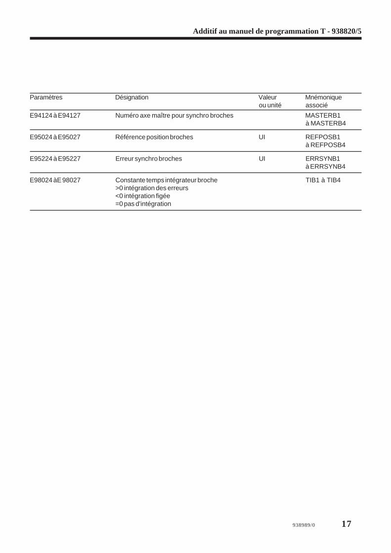
E94124 à E94127 Numéro axe maître pour synchro broches MASTERB1à MASTERB4
E95024 à E95027 Référence position broches UI REFPOSB1à REFPOSB4
E95224 à E95227 Erreur synchro broches UI ERRSYNB1à ERRSYNB4
E98024 àE 98027 Constante temps intégrateur broche TIB1 à TIB4>0 intégration des erreurs<0 intégration figée=0 pas d'intégration
18 938989/0
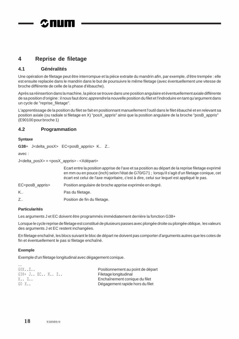
4 Reprise de filetage
4.1 Généralités
Une opération de filetage peut être interrompue et la pièce extraite du mandrin afin, par exemple, d'être trempée : elleest ensuite replacée dans le mandrin dans le but de poursuivre le même filetage (avec éventuellement une vitesse debroche différente de celle de la phase d'ébauche).
Après sa réinsertion dans la machine, la pièce se trouve dans une position angulaire et éventuellement axiale différentede sa position d'origine : il nous faut donc apprendre la nouvelle position du filet et l'indroduire en tant qu'argument dansun cycle de "reprise_filetage".
L'apprentissage de la position du filet se fait en positionnant manuellement l'outil dans le filet ébauché et en relevant saposition axiale (ou radiale si filetage en X) "posX_appris" ainsi que la position angulaire de la broche "posB_appris"(E90100 pour broche 1)
4.2 Programmation
Syntaxe
G38+ J<delta_posX> EC<posB_appris> K.. Z..
avec :
J<delta_posX> = <posX_appris> - <Xdépart>
Ecart entre la position apprise de l'axe et sa position au départ de la reprise filetage expriméen mm ou en pouce (inch) selon l'état de G70/G71 ; lorsqu'il s'agit d'un filetage conique, cetécart est celui de l'axe majoritaire, c'est à dire, celui sur lequel est appliqué le pas.
EC<posB_appris> Position angulaire de broche apprise exprimée en degré.
K.. Pas du filetage.
Z.. Position de fin du filetage.
Particularités
Les arguments J et EC doivent être programmés immédiatement derrière la fonction G38+
Lorsque le cycle reprise de filetage est constitué de plusieurs passes avec plongée droite ou plongée oblique, les valeursdes arguments J et EC restent inchangées.
En filetage enchaîné, les blocs suivant le bloc de départ ne doivent pas comporter d'arguments autres que les cotes defin et éventuellement le pas si filetage enchaîné.
Exemple
Exemple d'un filetage longitudinal avec dégagement conique.
...G0X..Z.. Positionnement au point de départG38+ J.. EC.. K.. Z.. Filetage longitudinalX.. Z.. Enchaînement conique du filetG0 X.. Dégagement rapide hors du filet

938989/0 19
Additif au manuel de programmation T - 938820/5
4.3 Contraintes
Afin de permettre une sortie de filet à la volée la fonction UGV est interdite en reprise de filetage ; si elle est présentelors de l'analyse du G38+ elle sera automatiquement révoquée (E11012 = 0)
Les gains des axes doivent être correctement réglés conformément à la constante de temps de la boucle de positionparamètre machine P56.
La broche doit être en régime établi de vitesse avant l'éxécution du bloc G38+.
4.4 Intégration de la fonction G38+ dans le cycle G33
4.4.1 Syntaxe de la reprise _filetage dans l'appel du cycle G33
Les positions apprises sont déclarées dans EC.. pour la position broche et dans EZ.. ou EX.. pour l'axe, selon qu'il s'agitd'un filetage axial ou radial ; c'est la déclaration de ces deux arguments qui distingue le filetage standard de la reprisede filetage.
G33 X.. Z.. P.. EZ.. EC.. K.. [S..] [R..] [EA..] [EB..] [F..]
Le calcul de l'écart de l'axe entre la position apprise de l'axe et sa position de départ est fait dans la macro %10033 ainsique son affectation à la fonction J derrière un G38+.
La macro %10033 s'assure de la cohérence de la syntaxe :
Elle vérifie que la position apprise de la broche et la position apprise sur l'axe du filet (axe majoritaire) sontprogrammées ; dans le cas d'un filetage conique à 45° l'un ou l'autre axe est indifféremment accepté.
En cas d'erreur, elle affiche le message numéro 838 : "reprise_filetage : données incohérentes".

20 938989/0
5 Evolution et mises à jour diverses
5.1 Création des fichiers CN
Afin d'éviter des problèmes de transferts et d'archivage de fichiers , il est nécessaire d'utiliser les numéros suivants :- de 1 à 9999.9 pour les programmes principaux,- de 10100 à 10255 pour les cycles,- de 20100, 20200, 20300 et 20400 pour les messages,- 11000 pour RAZ.
5.2 Chapitre 6.5 "Affichage d'un message avec réponse de l'opérateur"
Ne pas tenir compte de la deuxième remarque du chapitre 6.5.
5.3 Cycle de prise d'origine automatiqueTrois programmes-pièce transférables par UT3 permettent d'exécuter une POM automatique sur les machines équipéesde codeurs incrémentaux (y compris les machines équipées d'un où plusieurs couples d'axes synchronisés).
Les macros reconnaissent le type d'axe (linéaire, modulo ou à débattement limité) et génèrent le cycle nécessaire.
Si l'axe est la butée , un dégagement est programmé.
Liste des macros
% 9990 Exemple de POM automatique pour centre d'usinage mono-groupe
%10159 Macro de POM appelée par fonction G159 - mode CONT ou IMD
%9990.9 Macro de POM appelée par les précédents - Argument : L0 = nom symbolique de l'axe
REMARQUE Le programme % 9990 doit être personnalisé
5.3.1 Mode POM
Sur les machines mono-groupe, la POM est faite axe par axe, dans un ordre et avec une vitesse qu'il appartient depréciser dans le programme %9990.
Sur les machines multi-groupes, il faut renommer le programme %9990 livré en %9990.i de façon à avoir un programmepar groupe CN ; pour chaque groupe la POM est faite axe par axe, dans un ordre et avec une vitesse qu'il appartient depréciser dans la macro %9990.i ; de plus, il faut programmer les synchros nécessaires.
Personnalisation du programme %9990 pour une machine mono-groupe
Exemple de programme : on veut faire la POM dans l'ordre suivant Z puis X, Y et enfin C%9990IF [.RG80] = 159 THEN (appel par G159) G77 H9990.9ELSE (appel en mode POM : mettre dans L0 n° prog. de l'axe) (Eventuellement programmer la vitesse adéquate Fxxx) L0=2 F2000 G77 H9990.9 (axe Z) L0=0 F3000 G77 H9990.9 (axe X) L0=1 G77 H9990.9 (axe Y) L0=8 F10000 G77 H9990.9 (axe C) M2
938989/0 21
Additif au manuel de programmation T - 938820/5
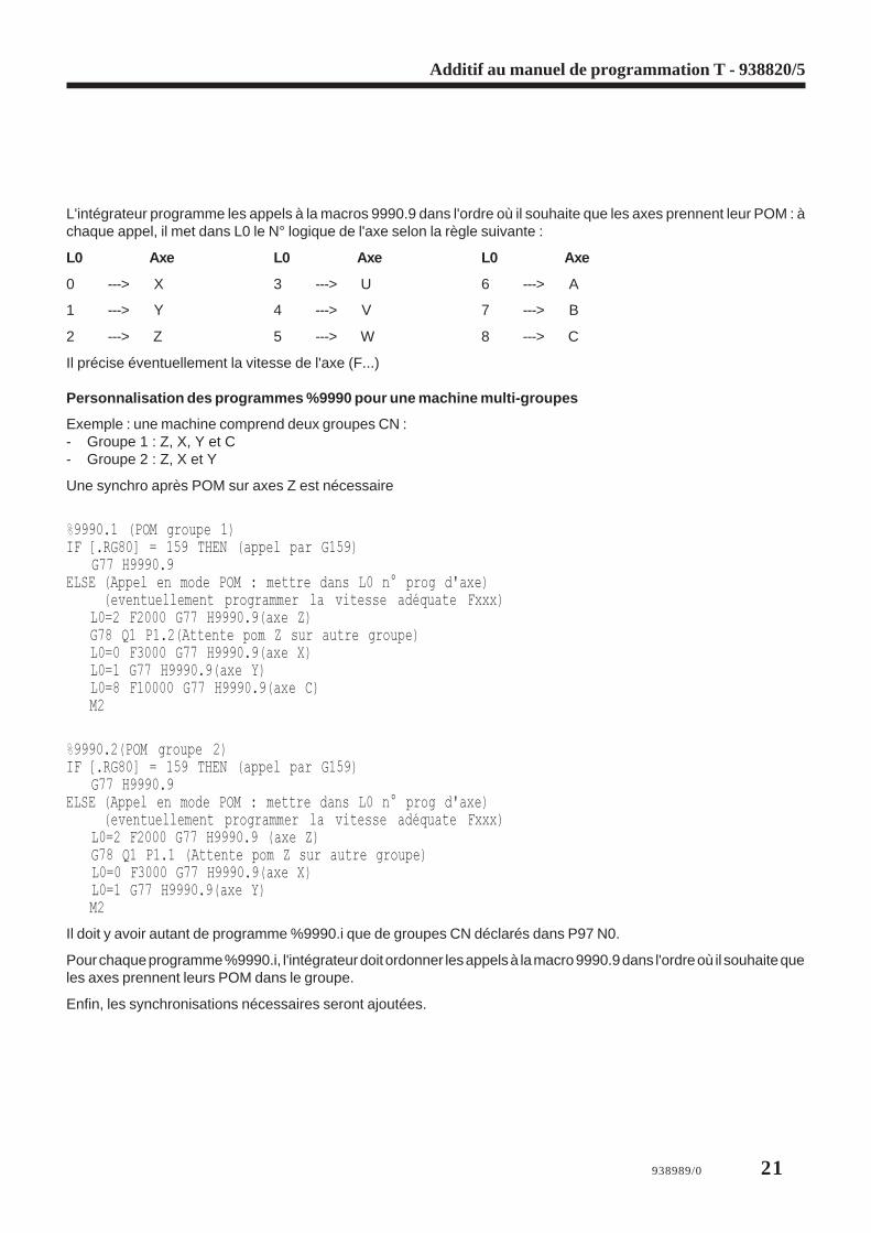
L'intégrateur programme les appels à la macros 9990.9 dans l'ordre où il souhaite que les axes prennent leur POM : àchaque appel, il met dans L0 le N° logique de l'axe selon la règle suivante :
L0 Axe L0 Axe L0 Axe
0 ---> X 3 ---> U 6 ---> A
1 ---> Y 4 ---> V 7 ---> B
2 ---> Z 5 ---> W 8 ---> C
Il précise éventuellement la vitesse de l'axe (F...)
Personnalisation des programmes %9990 pour une machine multi-groupes
Exemple : une machine comprend deux groupes CN :- Groupe 1 : Z, X, Y et C- Groupe 2 : Z, X et Y
Une synchro après POM sur axes Z est nécessaire
%9990.1 (POM groupe 1)IF [.RG80] = 159 THEN (appel par G159) G77 H9990.9ELSE (Appel en mode POM : mettre dans L0 n° prog d'axe) (eventuellement programmer la vitesse adéquate Fxxx) L0=2 F2000 G77 H9990.9(axe Z) G78 Q1 P1.2(Attente pom Z sur autre groupe) L0=0 F3000 G77 H9990.9(axe X) L0=1 G77 H9990.9(axe Y) L0=8 F10000 G77 H9990.9(axe C) M2
%9990.2(POM groupe 2)IF [.RG80] = 159 THEN (appel par G159) G77 H9990.9ELSE (Appel en mode POM : mettre dans L0 n° prog d'axe) (eventuellement programmer la vitesse adéquate Fxxx) L0=2 F2000 G77 H9990.9 (axe Z) G78 Q1 P1.1 (Attente pom Z sur autre groupe) L0=0 F3000 G77 H9990.9(axe X) L0=1 G77 H9990.9(axe Y) M2
Il doit y avoir autant de programme %9990.i que de groupes CN déclarés dans P97 N0.
Pour chaque programme %9990.i, l'intégrateur doit ordonner les appels à la macro 9990.9 dans l'ordre où il souhaite queles axes prennent leurs POM dans le groupe.
Enfin, les synchronisations nécessaires seront ajoutées.
22 938989/0
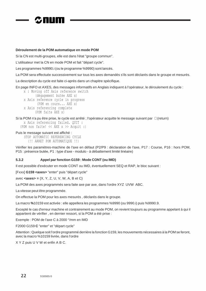
Déroulement de la POM automatique en mode POM
Si la CN est multi-groupes, elle est dans l'état "groupe commun".
L'utilisateur met la CN en mode POM et fait "départ cycle".
Les programmes %9990.i (ou le programme %9990) sont lancés.
La POM sera effectuée successivement sur tous les axes demandés s'ils sont déclarés dans le groupe et mesurés.
La description du cycle est faite ci-après dans un chapitre spécifique.
En page INFO et AXES, des messages informatifs en Anglais indiquent à l'opérateur, le déroulement du cycle : x : Moving off Axis reference switch (dégagement butée AXE x) x Axis reference cycle in progress (POM en cours... AXE x) x Axis referencing complete (POM faite AXE x)
Si la POM n'a pu être prise, le cycle est arrêté ; l'opérateur acquitte le message suivant par ↵ (return) x Axis referencing failed. QUIT : (POM non faite! << AXE x >> Acquit :)
Puis le message suivant est affiché : STOP AUTOMATIC REFERENCING CYCLE (!! ARRET POM AUTOMATIQUE !!)
Vérifier les paramètres-machine de l'axe en défaut (P2/P9 : déclaration de l'axe, P17 : Course, P16 : hors POM,P15 : présence butée, P1 : type d'axe - modulo - à débattement limité linéaire)
5.3.2 Appel par fonction G159 : Mode CONT (ou IMD)
Il est possible d'exécuter en mode CONT ou IMD, éventuellement SEQ et RAP, le bloc suivant :
[Fxxx] G159 <axes> "enter" puis "départ cycle"
avec <axes> = {X, Y, Z, U, V, W, A, B et C}
La POM des axes programmés sera faite axe par axe, dans l'ordre XYZ UVW ABC.
La vitesse peut être programmée.
On effectue la POM pour les axes mesurés , déclarés dans le groupe.
La macro %10159 est activée : elle appellera les programmes %9990 (ou 9990.i) puis %9990.9.
Excepté le cas d'erreur machine et contrairement au mode POM, on revient toujours au programme appelant à qui ilappartient de vérifier , en dernier ressort, si la POM a été prise :
Exemple : POM de l'axe C à 2000 °/mm en IMD
F2000 G159 C "enter" et "départ cycle"
Attention : Quelque soit l'ordre programmé derrière la fonction G159, les mouvements nécessaires à la POM se feront,avec la macro %10159 livrée, dans l'ordre
X Y Z puis U V W et enfin A B C.

938989/0 23
Additif au manuel de programmation T - 938820/5
5.3.3 Axes synchronisés par paramètres machine
Quelque soit le type d'appel, par fonction G159 ou en mode POM, la macro 9990.9 détecte la présence d'axessynchronisés par paramètres-machine.
Si un seul "axe mené" à l'axe programmé est trouvé, la POM est conduite conjointement sur les axes "menant" et "mené".
La macro 9990.9 suppose identique les caractéristiques des axes "menant" et "mené" : type d'axe, sens de POM, course,présence butée, zone couverte par la butée, etc... .
Les P16 "orpom" peuvent être légèrement différents et donc les "0" codeurs atteints "presque ensemble" dans le mêmemouvement. Après la POM de l'axe "menant", la macro prolonge le mouvement d'une longueur égale à la différence desP16 entre "menant" et "mené" ; cf. variable symbolique [marge].
En fin de cycle, la macro contrôle que les deux axes sont dans le même état. Sinon elle affiche le message : MASTER/SLAVE AXIS REFERENCE INCOMPLETE (!!POM Axe menant ou mené non faite!!)- Si l'état est "POM faite" , le cycle est terminé.- Si les deux axes sont encore dans l'état "POM non faite" .
Dans le cas des axes "modulo", la macro relance un nouveau mouvement.
S'il a plusieurs axes "menés" à l'axe programmé, en début de cycle, la macro affiche le message suivant : MACRO 9990.9; ONLY CONTROLS ONE AXIS (la macro 9990.9 gère un seul axe mené)
Il faut alors envisager des adaptations du programme 9990.9. Cela consiste essentiellement à dupliquer les parties oùinterviennent la chaîne de caractères 'mne1' en les renommant 'mne2', 'mne3' etc... autant de fois qu'il y a d'axe "mené".Ces adaptations, très lourdes si elles sont générales, restent assez simples pour des cas particuliers. Elles seront faitesau cas par cas pour ces configurations exceptionnelles.
5.3.4 Commutation broche/axe C en DISC NT
Utilisation des paramètres suivants :
E353aa = yzaa compris entre 0 et 31z est assiocié au paramètre V260 du variateur (relatif au régulateur de vitesse)y est assiocié au paramètre V261 du variateur (relatif au régulateur de position)y, z prennent les valeurs 0 ou 1 selon que l'on veut appliquer le jeu de paramètres 1 (broche) ou 2 (axe C).
E942xx = yy signifie que la référence variateur xx est désormais associée au retour mesure (axe ou broche) d'adresseyy,xx = adresse physique de la sortie référence moteur de la broche ou de l'axe,yy = adresse physique du système de mesure
P70 N08 devra être à la valeur suivante FF FF FF 08 (capteur fictif @ 08 sur broche 1)
L'erreur 92 sera générée si : aa inexistant et/ou xx et/ou yy ne sont pas reconnues
Exemple : Broche 1 (@ 24)E35324 = 0 sélection des paramètres de brocheE94224 = 24 G4F1 association référence / mesure de brocheE91008 = 0 G4F1 axe C non asservi
Axe C (@ 8)E35324 = 11 sélection des paramètres de l'axe CE94224 = 8 G4F1 association référence / mesure axe CE91008 = 1 G4F1 axe C asservi

24 938989/0

938989/0 25
Addition to T programming manual - 938820/5
1 Changes to Rigid Tapping
1.1 Review: Rigid Tapping Cycle: G84
The rigid tapping cycle servoes the tool feed rate to the spindle rotation speed. The feed rate is calculated automaticallyfrom the spindle speed and programmed step.
The cycle allows tapping to be programmed on the X or Z axes. The feed rate and spindle speed override potentiometersare not inhibited during the cycle. The feed rate override potentiometer is inoperative during tapping as such, but is activeduring other operations.
1.2 Programming the Cycle
It is now unnecessary to programme function M05 with G84
Example: G84 Z-200 K1.25 EK2.5 M5
If function M05 is programmed in the rigid tapping cycle, the spindle is stopped at the end of tapping.
If function M05 is not programmed during the rigid tapping cycle, spindle rotation is restarted in the initial direction.
Function G84 can now be programmed in any of the 8 axis groups and use any one of the four spindles if they are suitable.
The remainder of the rigid tapping cycle is unchanged.
Execution of the Rigid Tapping Cycle
This cycle is performed under the same conditions as before.
The spindle must be controlled by the group in which the cycle is programmed.
At the end of G84, when dimension EH is reached (return to the dimension of the work plane on the machining axis),the spindle is placed in state M5 if M5 is programmed in the cycle.
At the end of tapping, Z is at the top of the hole:
If spindle rotation is reversed
The spindle slows down as per E9033b (initialised by P32 N48) until it stops, then starts rotating in the opposite direction.
Axis movements are restarted as soon as the spindle is rotating in the correct direction.
If the spindle is stopped by programming M5
The spindle slows down as per E9033b until it stops.
Axis movements are carried out during spindle deceleration.
1.3 Stopping the Rigid Tapping CycleIf Stop_broche goes high for a spindle during rigid tapping (%W22.i = 1 where i ∈ [0,3]), the spindle stops as does thesynchronised machining axis.
If Stop_broche goes low for a spindle after stopping rigid tapping (%W22.i = 0 where i ∈ [0,3]), the spindle is restartedand rigid tapping is resumed. The use of Stop_broche is reserved for emergencies.
When the spindle stops, a CNC reset (RAZ_CN) can be carried out and rigid tapping is cancelled.
Any available function including rigid tapping can be carried out in AUTO or MDI mode.

26 938989/0
1.4 Other Changes and Corrections
The new version of G84 allows rigid tapping to be carried out on systems to 0.1 µm.
The functions enabling or inhibiting geometric transformations (inch/metric, scaling factor, DAT, etc.) which are activeduring a G84 cycle (rigid tapping) are processed as follows:- The dimensions and pitch are counted in the active unit set by G70 (inch) or G71 (mm)- The scaling factor if enabled is applied to all the dimensions programmed in cycle G84 (X..Z, ER and EH) but not
to the pitch (K) and (EK)- The mirroring function on the tool axis is incompatible with G84 (rigid tapping).
Function G39+ (rigid tap removal) also operates in this way.
For the software up to and including version L, rigid tapping (G84) in inches or 0.1 µm caused the following problems:- When unit used was the inch, pitch K was divided by 2.54- During tap removal, the spindle speed was also divided by 2.54- Ratio EK displayed on the Info page was multiplied by 10- In 0.1 µm: the spindle speed was sometimes limited during tap removal, e.g. S60 G84 K1 EK2 ... resulted in tap
removal at S100 (instead of S120).
938989/0 27
Addition to T programming manual - 938820/5
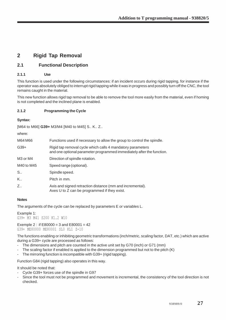
2 Rigid Tap Removal
2.1 Functional Description
2.1.1 Use
This function is used under the following circumstances: if an incident occurs during rigid tapping, for instance if theoperator was absolutely obliged to interrupt rigid tapping while it was in progress and possibly turn off the CNC, the toolremains caught in the material.
This new function allows rigid tap removal to be able to remove the tool more easily from the material, even if homingis not completed and the inclined plane is enabled.
2.1.2 Programming the Cycle
Syntax:
[M64 to M66] G39+ M3/M4 [M40 to M45] S.. K.. Z..
where:
M64 M66 Functions used if necessary to allow the group to control the spindle.
G39+ Rigid tap removal cycle which calls 4 mandatory parametersand one optional parameter programmed immediately after the function.
M3 or M4 Direction of spindle rotation.
M40 to M45 Speed range (optional).
S.. Spindle speed.
K.. Pitch in mm.
Z.. Axis and signed retraction distance (mm and incremental).Axes U to Z can be programmed if they exist.
Notes
The arguments of the cycle can be replaced by parameters E or variables L.
Example 1:G39+ M3 M41 S200 K1.2 W10
Exemple 2 : if E80000 = 3 and E80001 = 42G39+ ME80000 ME80001 SL0 KL1 Z-10
The functions enabling or inhibiting geometric transformations (inch/metric, scaling factor, DAT, etc.) which are activeduring a G39+ cycle are processed as follows:- The dimensions and pitch are counted in the active unit set by G70 (inch) or G71 (mm)- The scaling factor if enabled is applied to the dimension programmed but not to the pitch (K)- The mirroring function is incompatible with G39+ (rigid tapping).
Function G84 (rigid tapping) also operates in this way.
It should be noted that:- Cycle G39+ forces use of the spindle in G97- Since the tool must not be programmed and movement is incremental, the consistency of the tool direction is not
checked.

28 938989/0
2.1.3 Detectable Errors
Error 4: If option 20 is missing
Error 2: If one of the four mandatory arguments (M3/M4, S, K or Z) is missing
If another argument was programmed
If an M function other than M3/M4 or M40-M45 is programmed
If S is too large (>65536)
If K is negative or zero
Error 1: If the programmed axis does not exist
If several axes are programmed or the same axis is programmed several times
If M3/M4 or M40-M45 are programmed twice
If mirroring is active on the tapping axis
If the spindle is not in state M5
Error 39: If S is not compatible with the speed range programmed
If an automatic speed range search is necessary but not authorised [gamma not programmed and bit 7 ofP7 N0 equal to 1].
2.1.4 Execution of the Rigid Tap Removal Cycle
This cycle can be executed even if homing was not completed on the axis and/or spindle.
The inclined plane can be active.
The spindle must be controlled by the group in which the cycle is programmed.
At the beginning of the cycle, the spindle is in state M5.
For scaling of the spindle speed setting, the speed range which was active when tapping was interrupted must berecovered. If necessary, this speed range can be programmed in G39+. If the speed range is not programmed, theequivalent of an automatic speed range search will be performed, but the function will not be sent to the PLC.
The subroutines normally called by functions M3/M4 and M40-M45 are not executed.
At the beginning of the cycle, the spindle is controlled in the specified direction at the minimum spindle speed (P62 N1,N3, N5 or N7). Then the spindle is accelerated continuously up to the programmed speed S.
From the beginning of the cycle, movement on the Z axis is servoed to the spindle [G38] and the following error isminimised to comply with the specified pitch. The rigid tapping parameters set in P63 are used.
At the end of the cycle, when the travel is complete, the spindle is stopped and placed in its initial state. An internalM2 function is forced.
2.1.5 Particular Conditions for Tap Removal on Sight
Stop_Broche [%W22.0 to 3] is active and generates a deceleration on the spindle and axis.
REMARK A reset is possible provided the axis and spindle are immobile.
As for rigid tapping (during the tap removal phase):- The feed rate override potentiometer is forced to 100%- Cycle stop is active- The spindle speed override potentiometer is operative.

938989/0 29
Addition to T programming manual - 938820/5
3 Change in Spindle SynchronisationFor the software at index M, a different synchronisation principle is used, whereby the master spindle position is notservoed but is instead controlled in an open speed loop.
3.1 Functional Description of the Software
Notation conventions
BM denotes the Master Spindle or Master Spindle number and BE the Slave Spindle or Slave Spindle number.
The spindles are numbered from 0 to 3.
Spindles denoted simply B can be either a master or a slave spindle.
When a parameter E is written Exxxxx+B, xxxxx+B is the parameter number.
Example: For the slave spindle at address 1, E94124+BE = E94125.
3.1.1 Speed-Dependent Acceleration
To be consistent with real spindle acceleration capabilities (see Sec. 3.1), the user can select speed-dependentacceleration.
New parameters E90370+b and E90380+b are used to specify the maximum speed in rpm for the maximum torque andpower.
E90370+b = Nbase
E90380+b = Nmax
Speed-dependent acceleration is enabled by setting parameter E90360+b to a value above 0.
This function operates as follows:If N< E90370 THEN acceleration = maximum specified by E90330If E90370 < N < E90380 THEN acceleration = E90330 * E90370 / NIf N < E90380 THEN acceleration = E90330 * E90370 * E90380 / N2
REMARKS- This functionality can be used independently of synchronisation.- When a spindle is slave, acceleration is not managed on that spindle. The slave spindle (BE)
receives the setting from the master spindle (BM).- When a BM is has a higher dynamic range than a BE, the parameters of the BM must be set to
allow the BE to follow.- No check is made on the settings of parameters E90370 and E90380.
30 938989/0
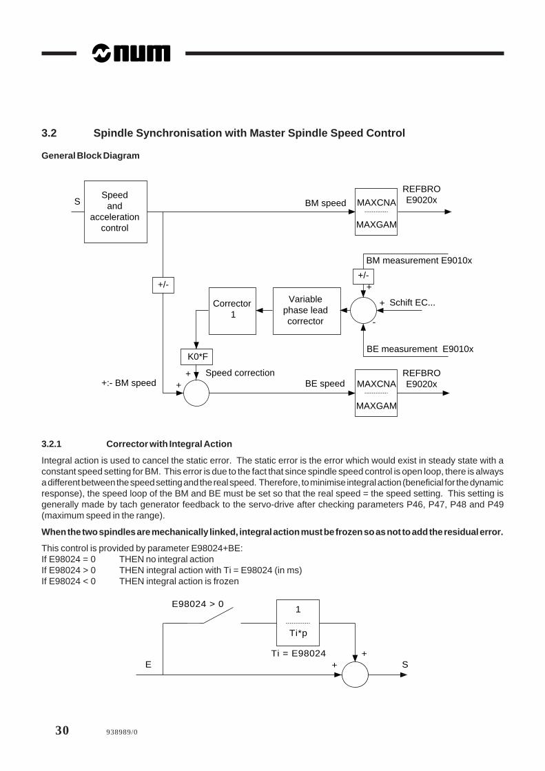
3.2 Spindle Synchronisation with Master Spindle Speed Control
General Block Diagram
MAXCNA
MAXGAM
+/-
Corrector 1
Variablephase leadcorrector
+/-
MAXCNA
MAXGAM
+:- BM speedSpeed correction
BE speed
BM speed
K0*F
REFBROE9020x
REFBROE9020x
BE measurement E9010x
BM measurement E9010x
Schift EC...
++
+
+
Speedand
accelerationcontrol
S
-
3.2.1 Corrector with Integral Action
Integral action is used to cancel the static error. The static error is the error which would exist in steady state with aconstant speed setting for BM. This error is due to the fact that since spindle speed control is open loop, there is alwaysa different between the speed setting and the real speed. Therefore, to minimise integral action (beneficial for the dynamicresponse), the speed loop of the BM and BE must be set so that the real speed = the speed setting. This setting isgenerally made by tach generator feedback to the servo-drive after checking parameters P46, P47, P48 and P49(maximum speed in the range).
When the two spindles are mechanically linked, integral action must be frozen so as not to add the residual error.
This control is provided by parameter E98024+BE:If E98024 = 0 THEN no integral actionIf E98024 > 0 THEN integral action with Ti = E98024 (in ms)If E98024 < 0 THEN integral action is frozen
++
1
Ti*p
E98024 > 0
Ti = E98024SE
938989/0 31
Addition to T programming manual - 938820/5
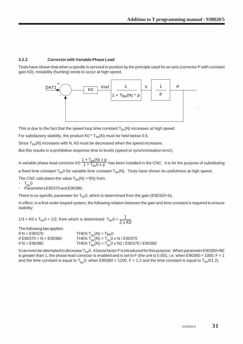
3.2.2 Corrector with Variable Phase Lead
Tests have shown that when a spindle is servoed in position by the principle used for an axis (corrector P with constantgain K0), instability (hunting) tends to occur at high speed.
DAT1+
-
K0Vref V P1
1 + Tbv(N) * p p
1
.
This is due to the fact that the speed loop time constant Tbv(N) increases at high speed.
For satisfactory stability, the product K0 * Tbv(N) must be held below 0.5.
Since Tbv(N) increases with N, K0 must be decreased when the speed increases.
But this results in a prohibitive response time to levels (speed or synchronisation error).
A variable phase lead corrector K0 1 + Tbv(N) x p1 + Tbv0 x p has been installed in the CNC. It is for the purpose of substituting
a fixed time constant Tbv0 for variable time constant Tbv(N). Tests have shown its usefulness at high speed.
The CNC calculates the value Tbv(N) = f(N) from:- Tbv0- Parameters E90370 and E90380.
There is no specific parameter for Tbv0, which is determined from the gain (E90320+b).
In effect, in a first-order looped system, the following relation between the gain and time constant is required to ensurestability:
1/3 < K0 x Tbv0 < 1/2, from which is determined Tbv0 ≈ 12 x K0
The following law applies:If N < E90370 THEN Tbv(N) = Tbv0If E90370 < N < E90380 THEN Tbv(N) = Tbv0 x N / E90370If N > E90380 THEN Tbv(N) = Tbv0 x N2 / E90370 / E90380
It can even be attempted to decrease Tbv0. A boost factor F is introduced for this purpose. When parameter E90360+BEis greater than 1, the phase lead corrector is enabled and is set to F (the unit is 0.001, i.e. when E90360 = 1000, F = 1and the time constant is equal to Tbv0; when E90360 = 1200, F = 1.2 and the time constant is equal to Tbv0/1.2).

32 938989/0
Response of the Corrector to a Level
The response of the corrector to a level depends on the speed. It has the following form:
0 <N1 < N2Tbv(N1) / Tbv0
Tbv(N2) / Tbv0
Remark concerning parameters E90370 and E90380
Parameters E90370 and E90380 are used to set both the acceleration and the time constant. This is not a problem, since:- The two uses are mutually exclusive: when the parameters are used to calculate the time constant, the spindle is
a slave, so the acceleration is not calculated and conversely- The settings for each type of use are related to the torque vs. speed characteristic of the motor and are close to Nbase
for E90370 and Nmax for E90380.
3.3 Man/Machine Interface
The synchronisation error is displayable by external parameter E95224+BE.
938989/0 33
Addition to T programming manual - 938820/5
3.4 Principle of Use of the Software Product
3.4.1 Setting Procedure
Adjust the speed loop for each spindle so that the measured speed is identical to the programmed speed.
Adjust the tach generator feedback signal on the servo-drive by checking the measured speed displayed on the Info page.
Cancel the acceleration ramps on the servo-drives.
If possible, set the spindle with the highest dynamic range as slave.
Set speed ranges Nbase and Nmax.
Plot the rotation speeds for maximum torques (Nbase) and maximum power (Nmax) on curve S1 of the motor catalogue.
Reference these speeds to the spindle if the motor/spindle gear ratio is not equal to 1.
Set parameters E90370+B = Nbase and E90380+B = Nmax.
Set the maximum master and slave acceleration E90330+B.
If the master has a higher dynamic range than the slave, make the settings according to the slave.
Set PI.
Set K0 = E90320+BE = 500 Ti = E98024+BE Fboost = E90360+BE = 1000
Set speed levels of 1000 rpm. Set K0 to have a satisfactory response of the synchronisation error.
Set Ti = E98024+BE = 500 ms. Then adjust to have an overshoot without oscillation.
Set higher levels. Then set rotation reversals. Check the behaviour. Adjust Nbase and Nmax of the slave if necessary.
If there is a large oscillation of the synchronisation error at high speed, increase Fboost and decrease Nmax of the slave.
3.4.2 Programming Spindle Synchronisation
Choice of Master
The request to synchronise a slave spindle to a master spindle is made in the part programme by loading the physicaladdress of the master spindle (24 + BM) in parameter E94124+BE.
Example: Spindles 0 and 1 slave, spindle 3 master E94124 = 27, E94125 = 27
Synchronisation is refused with error 94 if homing is not completed on BM and BE.
Selecting Forward or Reverse Synchronisation
The direction of rotation (M3 or M4) must be programmed for BM and BE before requesting synchronisation. Thisdetermines the synchronisation mode: if both spindles rotate in the same direction, synchronisation is forward; otherwiseit is reverse.

34 938989/0
Programming the Angle
The setting of function EC determines the angle between the positions of the master spindle and slave spindle duringsynchronisation. BE position = +/- (BM position + EC). EC is programmed in degrees.
Selecting the Type of Synchronisation
If the spindles are not servoed in position when synchronisation is requested, synchronisation is performed accordingto the principle described herein. Otherwise, servoed spindle synchronisation with automatic gain control is used.
Master Spindle Acceleration Parameters
The parameters concerning acceleration of the master spindle must be set before requesting synchronisation:
E90330+BM Max. acceleration in deg/s2. If not specified, the setting of parameter P32 is used as default
E90370+BM Nbase Maximum speed at maximum torque in rpm
E90380+BM Nmax Maximum speed at maximum power in rpm
E90360+BM If > 0, enabling of acceleration = f(N)
It should be noted that if BE has a lower dynamic range than BM, the characteristics of BE must be used, or else BEwill not be able to follow BM during accelerations.
Slave Spindle Servoing Parameters
The following parameters concerning the slave spindle must be set before requesting synchronisation:
E90320+BE Position loop gain K0 in rpm/rev
E90370+BE Maximum speed for Tbv(N)=Tbv0 (E90370 = Nbase)
E90380+BE Maximum speed N2 for calculation of Tbv(N) (E90380 = Nmax)
E90360+BE Boost factor F
E98024+BE Integral action time constant in ms
Enabling and Disabling Integral Action
Integral action is used to cancel the static error. It must be active during the synchronisation phase. When the twospindles are mechanically linked (e.g. during part off), integral action must mandatorily be frozen at the value it had atthe time of mechanical linkage.
E98024+BE = 0 No integral action
E98024+BE > 0 Integral action with Ti = E98024+BE (in ms)
E98024+BE < 0 Integral action frozen

938989/0 35
Addition to T programming manual - 938820/5
Synchronisation Error and Tolerance
The synchronisation error (difference between the measured positions) is read in E95224+BE (in internal units). Whenit is less than the tolerance loaded in parameter P44 or programmed in E90310+BE (in rev/65536), the spindle-in-positionreport is sent to the PLC (%R13.B) and Boolean E93524+BE goes high.
Programming Example
(SPEED CONTROLLED SPINDLE SYNCHRONISATION)(MASTER = B1 SLAVE = B2)WHILE E91124=1 DO $Homing on spindle 1M64M40M3S50%ENDWWHILE E91125=1 DO $Homing on broche 2M65M40M3S50ENDWE94124=-1 Cancel synchronisation on spindle 1E94125=-1 Cancel synchronisation on spindle 2E91024=0 Speed control on spindle 1E91025=0 Speed control on spindle 2E90330=20000 Max. accel. on spindle 1 in deg/s2
E90331=20000 Max. accel. on spindle 2E90370=1500 Nbase speed at max. torque on spindle 1 in rpmE90371=1500 Nbase speed at max. torque on spindle 2E90380=4000 Nmax speed at max. power on spindle 1 in rpmE90381=4000 Nmax speed at max. power on spindle 2E90321=500 Gain on spindle 2 in rpm/revE98025=500 Ti on spindle 2 in msE90360=1 Enable acceleration = f[N] on masterE90361=1000 Enable phase lead corrector on slaveM64 M40 M4 S100 EC0 Start spindle 1M65 M40 M4 S100 Start spindle 2E94125=24 Synchronise spindle 2 with master spindle 1WHILE E93525=0 DO G4 F.5 $ Wait for synchronisation at 100 rpmENDW$SYNCHRO OKM64 M40 M3 S2000WHILE E93525=0 DO G4 F.5 $Wait for synchronisation at 2000 rpmENDWE98025=-E98025 Integral action frozenG4 F5E98025=-E98025 Integral action restoredG4 F5M2

36 938989/0
3.5 List of Parameters E Relative to Spindles
The table below lists the external parameters and associated mnemonics.
The parameter can be programmed by its number or its mnemonic.
Example: E90113 is equivalent to E[MODULOB4]
Parameter Description Value Associatedor unit mnemonic
E79000 Position measurement E90100 B.group MESPOSBG
E79001 Speed reference E90200 B.group REFVITBG
E90100 to E90103 Spindle position measurement 1/100000 MESPOSB1to MESPOSB4
E90110 to E90113 Modulo spindles MODULOB1to MODULOB4
E90200 to E90203 Spindle speed reference REFVITB1to REFVITB4
E90300 to E90303 Maximum spindle speed with indexing VITPALB1to VITPALB4
E90310 to E90313 In-position or synchronisation window (P44) FENETRE1to FENETRE4
E90320 to E90323 Spindle position loop gain (P45) rpm/rev GAINB1 to GAINB4
E90330 to E90333 Spindle acceleration deg/s2 ACCB1 to ACCB4
E90360 to E90363 On master spindle, enable and management 1/1000 ACCKFNB1On slave spindle, phase lead boost factor to ACCKFNB4
E90370 to E90373 Nbase
spindle rotation speed at maximum torque rpm N_CMAXB1to N_CMAXB4
E90380 to E90383 Nmax
spindle rotation speed at maximum power rpm N_PMAXB1to N_PMAXB4
E90390 to E90393 Maximum calculated speed in range MAXGANB1when integral action is frozen to MAXGAMB4
E90124 to E90127 Axes 24 to 27 or servoed spindles ASS_B1to ASS_B4
E91124 to 91127 Homing not completed on axes 24 to 27 or spindles POM_B1to POM_ B4
E93525 to 93527 Axes 24 to 27 or synchronised spindles POS_B1to POS_B4
938989/0 37
Addition to T programming manual - 938820/5
Parameter Description Value Associatedor unit mnemonic
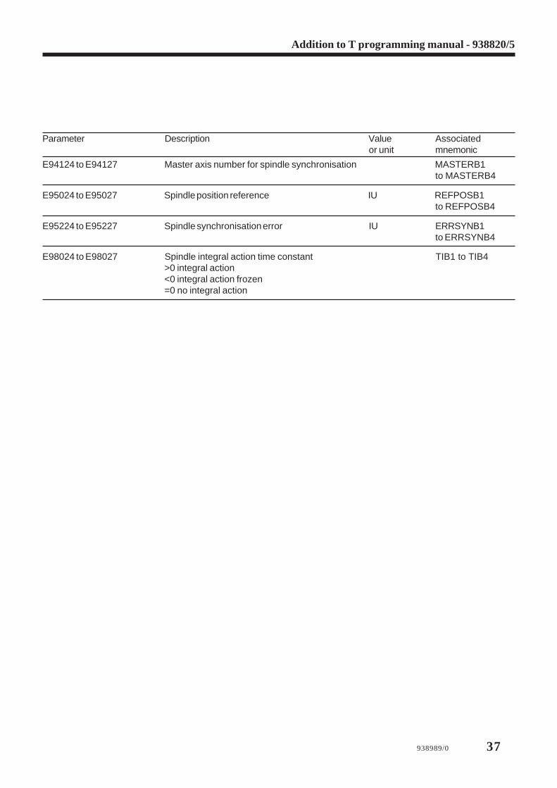
E94124 to E94127 Master axis number for spindle synchronisation MASTERB1to MASTERB4
E95024 to E95027 Spindle position reference IU REFPOSB1to REFPOSB4
E95224 to E95227 Spindle synchronisation error IU ERRSYNB1to ERRSYNB4
E98024 to E98027 Spindle integral action time constant TIB1 to TIB4>0 integral action<0 integral action frozen=0 no integral action

38 938989/0
4 Resumption of Thread Cutting
4.1 General
Thread cutting may be interrupted and the part removed from the chuck, for instance for quenching. It is then reinstalledin the chuck to continue the thread cutting operation (possibly using a different spindle speed than during roughing).
When reinstalled in the chuck, the part is in a different angular position (and possibly a different axial position) than before.It is therefore necessary to teach in the new position of the thread and use it as argument in a reprise_filetage (resumedthread cutting) cycle.
Teach-in of the thread position is carried out manually by positioning the tool in the roughed thread and measuring theaxial position) (or radial position for thread cutting in X) called Xpos_teachin as well as the angular position of the spindleSpos_teachin (E90100 for spindle 1).
4.2 Programming
Syntax
G38+ J<Xpos_delta> EC<Spos_teachin> K.. Z..
where:
J<Xpos_delta> = <Xpos_teachin> - <Xdépart>
Difference between the teach-in position of the axis and its start point when thread cutting isresumed, expressed in mm or inches, depending on whether G71 or G70 is programmed. Fora taper thread, the difference is that of the major axis, i.e., the axis to which the pitch applies.
EC<Spos_teachin> Teach-in angular spindle position in degrees.
K.. Thread pitch.
Z.. Thread cutting end point.
Notes
Arguments J and EC must be programmed immediately after function G38+.
When the resumed thread cutting cycle includes several passes with straight or oblique infeed, the values of argumentsJ and EC remain unchanged.
For sequenced thread cutting, the blocks after the initial block must not include any arguments except the end point andpossibly the pitch.
Example
Example of longitudinal thread cutting with tapered retraction
...G0X..Z.. Positioning at the start pointG38+ J.. EC.. K.. Z.. Longitudinal thread cuttingX.. Z.. Tapered sequencing of the threadG0 X.. Rapid retraction off the thread

938989/0 39
Addition to T programming manual - 938820/5
4.3 Constraints
High-speed machining is prohibited for resumed thread cutting to allow on-the-fly exit from the thread. If this functionis active when G38+ is analysed, it is automatically cancelled (E11012 = 0).
The gains on the axes must be set consistently with the position loop time constant set in machine parameter P56.
The spindle must be rotating at steady speed before the block containing G38+ is executed.
4.4 Inclusion of function G38+ in Cycle G33
4.4.1 Syntax of Resumed Thread Cutting Included in the Call to Cycle G33
The teach-in positions are declared in EC.. for the spindle position and EZ.. or EX.. for the axis, depending on whetherthread cutting is axial or radial. The presence of these two arguments distinguishes between normal and resumed threadcutting.
G33 X.. Z.. P.. EZ.. EC.. K.. [S..] [R..] [EA..] [EB..] [F..]
The difference between the teach-in position of the axis and its initial position is calculated in macro %10033 as wellas its assignment to function J after G38+.
Macro %10033 ensures that the syntax is consistent:
It checks that both the teach-in position of the spindle and the teach-in position on the thread axis (major axis) areprogrammed. For a 45-degree taper thread, either axis is accepted.
In case of an error, it displays the message No 838: $ Restart threading incoherent data.

40 938989/0
5 Miscellaneous Changes and Updates
5.1 Creation of CNC Files
Always use the following numbering to avoid file transfer and backup problems:- 1-9999.9 for main programs- 10100-10255 for cycles- 20100, 20200, 20300 and 20400 for messages- 11000 for Reset.
5.2 Section 6.5, Message display with wait operator response
Ignore the second remark on section 6.5.
5.3 Automatic Homing CycleThree part programmes transferable by UT3 are used to perform automatic homing or referencing on machines equippedwith incremental encoders (including machines with one or more synchronised axis pairs).
The macros recognise the type of axis (linear, modulo or with limited excursion) and generate the necessary cycle.
If the axis is the reference switch, a retraction is programmed.
List of Macros
% 9990 Example of automatic homing for machining centres with one axis group
%10159 Homing macro called by function G159, AUTO or MDI mode
%9990.9 Homing macro called by the above macros. Argument L0 = symbolic name of the axis.
REMARK Programme %9990 must be customised.
5.3.1 Homing Mode
On machines with a single axis group, homing is performed on each axis. The order and speed must be specified inprogramme %9990.
On machines with multiple axis groups, programme %9990 supplied must be renamed %9990.i to have a differentprogramme for each CNC group. Homing is performed on each axis. The order and speed must be specified in programme%9990.i. In addition, the required synchronisations must be programmed.
Customising Programme %9990 for a Machine with One Axis Group
Example of programme: Homing is to be carried out first on Z, then on X and Y and last on C.%9990IF [.RG80] = 159 THEN (call by G159) G77 H9990.9ELSE (call in homing mode: load axis no. in L0) (Programme the feed rate Fxxx if required) L0=2 F2000 G77 H9990.9 (Z axis) L0=0 F3000 G77 H9990.9 (X axis) L0=1 G77 H9990.9 (Y axis) L0=8 F10000 G77 H9990.9 (C axis) M2
938989/0 41
Addition to T programming manual - 938820/5
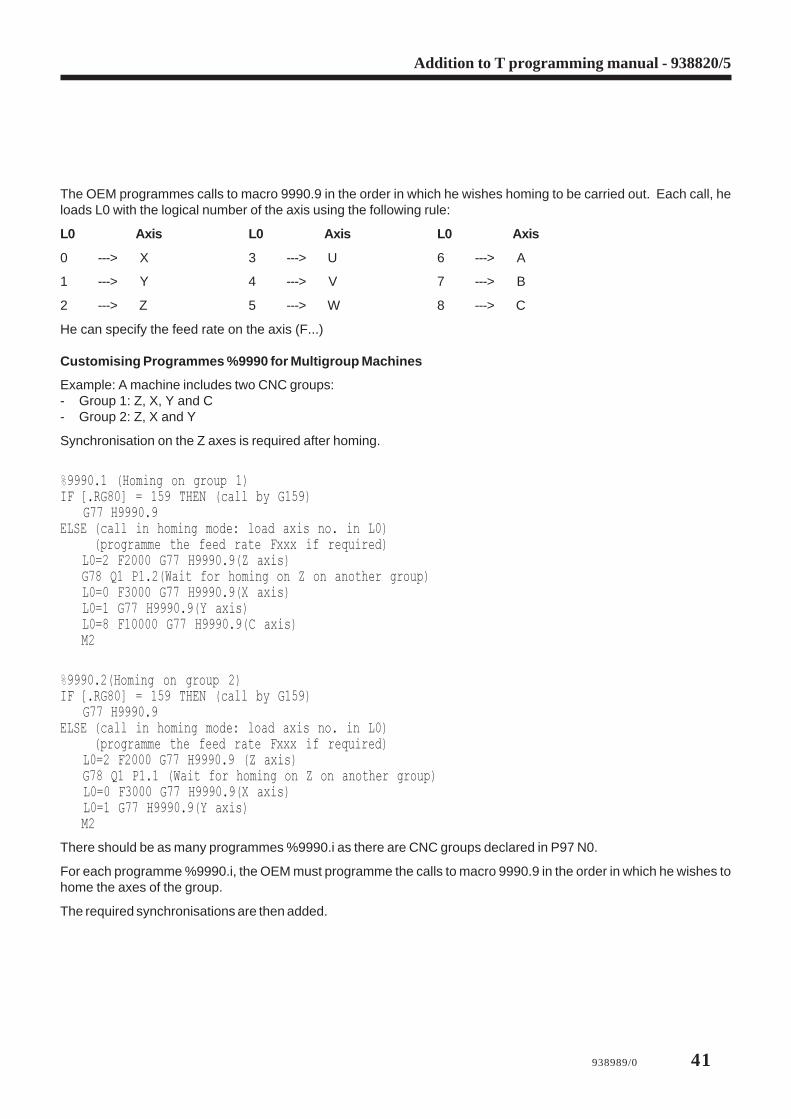
The OEM programmes calls to macro 9990.9 in the order in which he wishes homing to be carried out. Each call, heloads L0 with the logical number of the axis using the following rule:
L0 Axis L0 Axis L0 Axis
0 ---> X 3 ---> U 6 ---> A
1 ---> Y 4 ---> V 7 ---> B
2 ---> Z 5 ---> W 8 ---> C
He can specify the feed rate on the axis (F...)
Customising Programmes %9990 for Multigroup Machines
Example: A machine includes two CNC groups:- Group 1: Z, X, Y and C- Group 2: Z, X and Y
Synchronisation on the Z axes is required after homing.
%9990.1 (Homing on group 1)IF [.RG80] = 159 THEN (call by G159) G77 H9990.9ELSE (call in homing mode: load axis no. in L0) (programme the feed rate Fxxx if required) L0=2 F2000 G77 H9990.9(Z axis) G78 Q1 P1.2(Wait for homing on Z on another group) L0=0 F3000 G77 H9990.9(X axis) L0=1 G77 H9990.9(Y axis) L0=8 F10000 G77 H9990.9(C axis) M2
%9990.2(Homing on group 2)IF [.RG80] = 159 THEN (call by G159) G77 H9990.9ELSE (call in homing mode: load axis no. in L0) (programme the feed rate Fxxx if required) L0=2 F2000 G77 H9990.9 (Z axis) G78 Q1 P1.1 (Wait for homing on Z on another group) L0=0 F3000 G77 H9990.9(X axis) L0=1 G77 H9990.9(Y axis) M2
There should be as many programmes %9990.i as there are CNC groups declared in P97 N0.
For each programme %9990.i, the OEM must programme the calls to macro 9990.9 in the order in which he wishes tohome the axes of the group.
The required synchronisations are then added.

42 938989/0
Automatic Homing Procedure in Homing Mode
A multigroup CNC must be in common group state.
The user places the CNC in homing mode and presses the Cycle start button.
Programmes %9990.i (or programme %9990) are (is) started.
Homing is performed on each of the axes requested if they are declared in the group and measured.
The cycle is described below in a special section.
On the Info and Axes pages, English messages inform the operator of progress of the cycle: x : Moving off Axis reference switch
x Axis reference cycle in progress
x Axis referencing complete
If homing was not possible, the cycle is stopped. The operator acknowledges the message below by pressing ↵ (return) x Axis referencing failed. QUIT :
The following message is then displayed: STOP AUTOMATIC REFERENCING CYCLE
Check the machine parameters of the axis on which homing failed (P2/P9: Axis declaration; P17: Travel limits; P16:Reference switch position; P15: Direction of homing; P1: Axis type - modulo and limited excursion, linear).
5.3.2 Call by Function G159: AUTO (or MDI) Mode
The following block can be executed in AUTO or MDI mode and also possibly in SINGLE and DRYRUN modes:
[Fxxx] G159 <axes> Enter and Cycle start
where <axes> = {X, Y, Z, U, V, W, A, B and C}
Homing is performed on each of the programmed axes in the order XYZ UVW ABC.
The feed rate can be programmed.
Homing is performed on the measured axes declared in the group.
Macro %10159 is activated and calls programmes %9990 (or 9990.i) then %9990.9.
Except in the case of a machine error, and contrary to homing mode, a return is always made to the calling programme,which is responsible for checking whether homing was effective:
Example: Homing of the C axis at 2000 deg/mm in MDI mode
F2000 G159 C Enter and Cycle start
Caution: Regardless of the order of the axes programmed after G159, the movements required for homing are carriedout in the order XYZ, then UVW and finally ABC by macro %10159 as delivered.

938989/0 43
Addition to T programming manual - 938820/5
5.3.3 Axes Synchronised by Machine Parameters
Regardless whether it is called by function G159 or in homing mode, macro 9990.9 detects the presence of axessynchronised by machine parameters.
If only one axis is slaved to the programmed axis, homing is conducted jointly on the master and slave axes.
Macro 9990.9 assumes that the master and slave axes have the same characteristics: type, homing direction, travel,switch presence, area covered by the switch, etc.
Parameters P16 (reference switch position) may be slightly different for the two axes and therefore the encoder markerpulses may be reached “almost together” in the same movement. After homing the master axis, the macro continuesmovement over a length equal to the difference between P16 for the master and slave axes. See the symbolic variable[marge] (margin).
At the end of the cycle, the macro checks that the two axes are in the same state. If not, it displays the message: MASTER/SLAVE AXIS REFERENCE INCOMPLETE
- If homing is complete on both axes, the cycle ends.- If both axes are still not homed.
The macro starts a new movement for modulo axes.
If several axes are slaved to the programmed axis, the macro displays the following message at the beginning of thecycle: MACRO 9990.9; ONLY CONTROLS ONE AXIS
Programme 9990.9 must then be adapted. This basically consists of duplicating the parts including character string mne1and renaming it mne2, mne3, ..., as many times as there are slave axes. These adaptations are very cumbersome ingeneral but are relatively simple for particular cases. They are performed on a case-by-case basis for such exceptionalconfigurations.
5.3.4 Spindle/C-axis switching in DISC NT
Use of the following parameters:
E353aa = yzaa between 0 and 31z is associated with the parameter V260 of the servo-drive (relating to speed controller)y is associated with the parameter V261 of the servo-drive (relating to position controller)y, z take the values 0 or 1 depending on whether one wants to apply parameter set 1 (spindle) or 2 (C-axis).
E942xx = yy means that the servo-drive reference xx is henceforth associated with the yy address measurement (axisor spindle) feedback,xx = physical address of the motor output reference of the spindle or axis,yy = physical address of the measurement system
P70 N08 must be at the following value FF FF FF 08 (fictitious sensor @ 08 on spindle 1)
Error 92 shall be generated if: aa is inexistent and/or xx and/or yy are not recognized
Example: Spindle 1 (@ 24)E35324 = 0 selection of spindle parametersE94224 = 24 G4F1 association of reference / spindle measurementE91008 = 0 G4F1 C-axis not servo-controlled
C-axis (@ 8)E35324 = 11 selection of the C-axis parametersE94224 = 8 G4F1 association of reference / C-axis measurementE91008 = 1 G4F1 C-axis servo-controlled

44 938989/0