Embed Size (px)
Citation preview
Copyright (c) 2009-2016 Lassalle Technologies. All Rights Reserved
AddFlow for WPF 2016 Tutorial
October 2016
Lassalle Technologies
http://www.lassalle.com
- page 1 -
Copyright (c) 2009-2016 Lassalle Technologies. All Rights Reserved
CONTENTS
1 Introduction ................................................................................................. 5
2 What's new in AddFlow for WPF 2016 ? ........................................................ 62.1 Compatibility ............................................................................................................ 6
2.2 New features ............................................................................................................ 6
2.3 Changes .................................................................................................................... 62.3.1 Two major changes ............................................................................................................................... 62.3.2 Pins ........................................................................................................................................................ 72.3.3 Renamed APIS ...................................................................................................................................... 72.3.4 Creation methods ................................................................................................................................. 8
3 Getting Started ............................................................................................. 93.1 Installation ................................................................................................................ 9
3.2 AddFlow DLLs ............................................................................................................ 9
3.3 Licensing ................................................................................................................. 103.3.1 Key Points ............................................................................................................................................ 103.3.2 Type of licenses ................................................................................................................................... 10
3.3.2.1 Editions ............................................................................................................. 103.3.2.2 Multi-pack discounts .............................................................................................. 103.3.2.3 Source code ........................................................................................................ 10
3.3.3 How it works? ..................................................................................................................................... 10
4 Interactive creation of a diagram ................................................................ 134.1 Overview ................................................................................................................ 13
4.2 Create a diagram interactively ................................................................................ 134.2.1 Draw a node ........................................................................................................................................ 134.2.2 Draw a link .......................................................................................................................................... 134.2.3 Stretch a link ....................................................................................................................................... 154.2.4 Draw a reflexive link ............................................................................................................................ 164.2.5 Multiselection ..................................................................................................................................... 164.2.6 Node rotation ...................................................................................................................................... 174.2.7 Change properties of a node or a link ................................................................................................ 184.2.8 Add a text to a node ............................................................................................................................ 184.2.9 Adjust the link origin and destination points ...................................................................................... 184.2.10 Change the destination or the origin node of a link ......................................................................... 19
5 Programmatic creation of a diagram ........................................................... 205.1 Overview ................................................................................................................ 20
5.2 AddFlow Items ........................................................................................................ 215.2.1 Item ..................................................................................................................................................... 215.2.2 ContentItem ........................................................................................................................................ 215.2.3 Node ................................................................................................................................................... 215.2.4 Link ..................................................................................................................................................... 215.2.5 Caption ................................................................................................................................................ 22
5.3 Collections of items ................................................................................................. 22
5.4 Creation and deletion of items ................................................................................ 225.4.1 Node .................................................................................................................................................... 22
- page 2 -
Copyright (c) 2009-2016 Lassalle Technologies. All Rights Reserved
5.4.2 Link ...................................................................................................................................................... 235.4.3 Caption ................................................................................................................................................ 23
5.5 Diagram creation .................................................................................................... 235.5.1 Our first program ................................................................................................................................ 235.5.2 Other ways to create the diagram ...................................................................................................... 245.5.3 Changing property values ................................................................................................................... 255.5.4 Default property values ...................................................................................................................... 275.5.5 The NodeModel, LinkModel and CaptionModel properties .............................................................. 285.5.6 Stretching the links ............................................................................................................................. 29
5.6 More informations about ContentItem objects and nodes ...................................... 305.6.1 ContentItem colors ............................................................................................................................. 315.6.2 ContentItem object text ..................................................................................................................... 315.6.3 ContentItem object custom shape ..................................................................................................... 315.6.4 Predefined shapes ............................................................................................................................... 325.6.5 ContentItem object image .................................................................................................................. 32
5.7 More informations about node pins ........................................................................ 34
5.8 More informations about links ................................................................................ 365.8.1 Link colors ........................................................................................................................................... 365.8.2 Link text .............................................................................................................................................. 365.8.3 Link arrows .......................................................................................................................................... 365.8.4 Link line styles ..................................................................................................................................... 37
5.9 More informations on Captions ............................................................................... 37
5.10 Displaying shadows ............................................................................................... 40
5.11 Custom visuals ...................................................................................................... 40
5.12 Displaying link intersections .................................................................................. 41
5.13 Diagram navigation ............................................................................................... 42
5.14 Selection of items .................................................................................................. 445.14.1 Interactive selection ......................................................................................................................... 445.14.2 Selection handles .............................................................................................................................. 445.14.3 Programmatic selection: ISelectable interface ................................................................................. 445.14.4 SelectedItems collection ................................................................................................................... 445.14.5 Selection event ................................................................................................................................. 455.14.6 Hit Testing ......................................................................................................................................... 45
5.15 Zooming ................................................................................................................ 45
5.16 Zordering .............................................................................................................. 45
5.17 Serialization .......................................................................................................... 46
5.18 Printing a diagram ................................................................................................. 46
5.19 Exporting a diagram in XAML ................................................................................ 46
5.20 Customizing the user interface .............................................................................. 48
6 Avanced topics ............................................................................................ 516.1 Undo/Redo ............................................................................................................. 51
6.1.1 General features ................................................................................................................................. 516.1.2 Updating the user interface ................................................................................................................ 516.1.3 Grouping basic actions ........................................................................................................................ 51
- page 3 -
Copyright (c) 2009-2016 Lassalle Technologies. All Rights Reserved
6.1.4 What can be undone and redone? ..................................................................................................... 516.1.5 Undo/Redo customization .................................................................................................................. 516.1.6 Undo/Redo API ................................................................................................................................... 53
6.2 Performance tuning ................................................................................................ 536.2.1 BeginUpdate and EndUpdate methods .............................................................................................. 536.2.2 IsVirtualizing property ......................................................................................................................... 536.2.3 Other tips for better performances .................................................................................................... 53
6.3 Data Customization ................................................................................................. 546.3.1 Framework's Tag property .................................................................................................................. 546.3.2 Attached properties ............................................................................................................................ 546.3.3 Derivation of Node and Link classes ................................................................................................... 54
7 Automatic Graph Layout ............................................................................. 557.1 Hierarchic layout ..................................................................................................... 55
7.1.1 Purpose ............................................................................................................................................... 557.1.2 Code example ..................................................................................................................................... 567.1.3 Limitation ............................................................................................................................................ 567.1.4 Side Effect ........................................................................................................................................... 56
7.2 Orthogonal layout ................................................................................................... 567.2.1 Purpose ............................................................................................................................................... 567.2.2 Code example ..................................................................................................................................... 577.2.3 Limitation ............................................................................................................................................ 577.2.4 Side Effect ........................................................................................................................................... 57
7.3 Symmetric layout .................................................................................................... 577.3.1 Purpose ............................................................................................................................................... 577.3.2 Code example ..................................................................................................................................... 587.3.3 Limitation ............................................................................................................................................ 587.3.4 Side Effect ........................................................................................................................................... 58
7.4 Series-parallel layout .............................................................................................. 587.4.1 Purpose ............................................................................................................................................... 587.4.2 Code example ..................................................................................................................................... 607.4.3 Limitation ............................................................................................................................................ 607.4.4 Side Effect ........................................................................................................................................... 60
7.5 Tree layout .............................................................................................................. 607.5.1 Purpose ............................................................................................................................................... 607.5.2 Code example ..................................................................................................................................... 617.5.3 Limitation ............................................................................................................................................ 627.5.4 Side Effect ........................................................................................................................................... 62
- page 4 -

Copyright (c) 2009-2016 Lassalle Technologies. All Rights Reserved
1 Introduction AddFlow for WPF 2016 is a general purpose Flowcharting/Diagramming WPF component, which lets you quickly build flowchart-enabled WPF applications.
AddFlow for WPF 2016 allows the creation and the manipulation of two-dimensional diagrams (a.k.a graphs). An AddFlow diagram is a set of objects called nodes (also called vertices or entities) that can be linked each other with links (also called edges, arcs or relations). These diagrams can be created programmatically or interactively.
Each time you need to graphically display interactive diagrams, you should consider using AddFlow, a royalty-free control that offers unique support to create diagrams interactively or programmatically: workflow diagrams, database diagrams, communication networks, organizational charts, process flows, state transitions diagrams, CTI applications, CRM (Customer Relationship Management), expert systems, graph theory, quality control diagrams, …
It has been created with VS 2013 and .NET Framework 4 on a 64 bits machine.
Purpose of this tutorial
This tutorial provides information on:
creating diagrams programmatically, using the AddFlow control and classes creating diagrams interactively installing AddFlow for WPF 2016 licensing
Who should use this tutorial?
This guide is intended for application programmers using the WPF platform to build WPF applications.
Samples
AddFlow for WPF 2016 is installed with one demo sample written in C#: DemoFlow. In this tutorial, we shall callit “the demo”. Its C# source code is also installed.
- page 5 -
Copyright (c) 2009-2016 Lassalle Technologies. All Rights Reserved
2 What's new in AddFlow for WPF 2016 ?
2.1 Compatibility
AddFlow For WPF 2016 is NOT compatible with the previous version.
Some changes were necessary:
to allow a better evolution of the product for the future to fix some design errors to provide a lighter product that just does its job and nothing more. for a better compatibility with other versions, especially the HTML5 and the Winforms versions of AddFlow.
However it is possible to load diagrams created with previous versions.
2.2 New features
There are new important features:
Virtualization mode allowing working quickly with very big diagrams. This is a UI virtualization where only the visible items are displayed. The IsVirtualizing property determines whether virtualizing mode is allowed or not.
Captions. A caption is like a label or a note. It is a new type of object allowing displaying a text or an image and that can be owned by any item.
Orthogonal links . A new link line style.
2.3 Changes
2.3.1 Two major changes
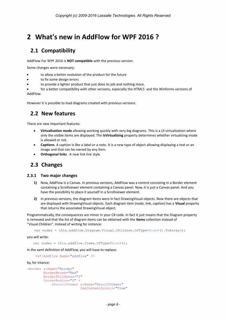
1) Now, AddFlow is a Canvas. In previous versions, AddFlow was a control consisting in a Border element containing a Scrollviewer element containing a Canvas panel. Now, it is just a Canvas panel. And you have the possibility to place it yourself in a Scrollviewer element.
2) In previous versions, the diagram items were in fact DrawingVisual objects. Now there are objects that are displayed with DrawingVisual objects. Each diagram item (node, link, caption) has a Visual propertythat returns the associated DrawingVisual object.
Programmatically, the consequences are minor in your C# code. In fact it just means that the Diagram property is removed and that the list of diagram items can be obtained with the Items collection instead of “Visual.Children". Instead of writing for instance:
var nodes = this.addflow.Diagram.Visual.Children.OfType<Node>().ToArray();
you will write:
var nodes = this.addflow.Items.OfType<Node>();
In the xaml definition of AddFlow, you will have to replace:
<af:AddFlow Name="addflow" />
by, for intance:
<Border x:Name="Border" BorderBrush="Red" BorderThickness="2" CornerRadius="2" > <ScrollViewer x:Name="ScrollViewer" CanContentScroll="True"
- page 6 -
Copyright (c) 2009-2016 Lassalle Technologies. All Rights Reserved
HorizontalScrollBarVisibility="Auto" VerticalScrollBarVisibility="Auto" Padding="1" Background="White" BorderBrush="Transparent" BorderThickness="0" Margin="1" IsTabStop="False"> <af:AddFlow Name="addflow" /> </ScrollViewer></Border>
The Border and ScrollViewer AddFlow properties are therefore removed.
TIP: Double click event
A consequence of this change is that the double click event is no more supported. The workaround is to use the ClickCount property of the parameter of the MouseLeftButtonDown event :
private void addflow_MouseLeftButtonDown(object sender, MouseButtonEventArgs e){ if (e.ClickCount == 2) // Double click { …
This is demonstrated in the demo provided with AddFlow in the Path and CustomUndo examples.
2.3.2 Pins
It is now easier to define and manage the node pins, using the PinsLayout property of the Node object.
The ConnectorStyle and Connector properties are removed.
The PinStyle AddFlow property is also removed and replaced by the PinSize, PinStroke, PinFill and PinShape properties.
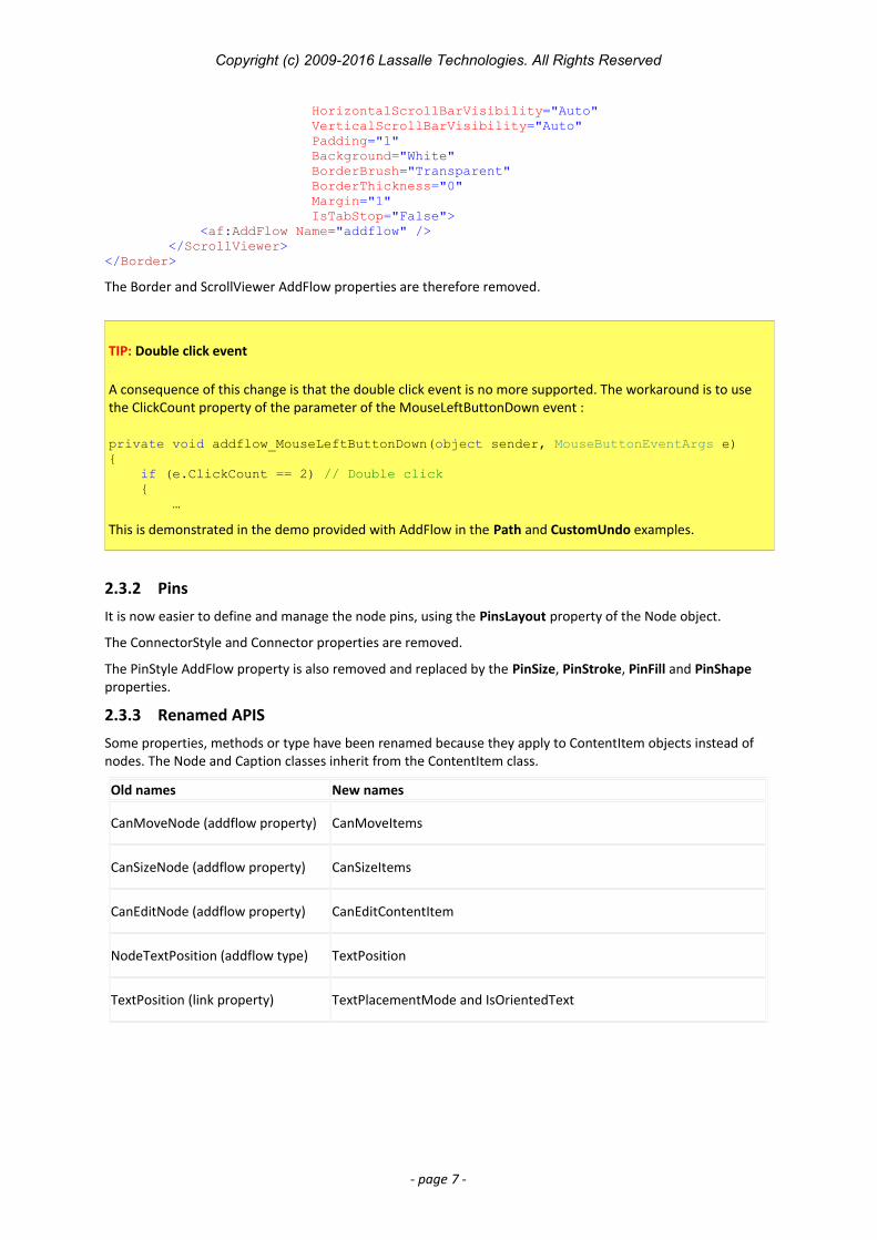
2.3.3 Renamed APIS
Some properties, methods or type have been renamed because they apply to ContentItem objects instead of nodes. The Node and Caption classes inherit from the ContentItem class.
Old names New names
CanMoveNode (addflow property) CanMoveItems
CanSizeNode (addflow property) CanSizeItems
CanEditNode (addflow property) CanEditContentItem
NodeTextPosition (addflow type) TextPosition
TextPosition (link property) TextPlacementMode and IsOrientedText
- page 7 -

Copyright (c) 2009-2016 Lassalle Technologies. All Rights Reserved
2.3.4 Creation methods
Now, there is only one version of the AddNode and AddLink methods, 3 versions of the Node constructor and 5 versions of the link constructor. (see the paragraph “Creation and deletion of items”)
- page 8 -
Copyright (c) 2009-2016 Lassalle Technologies. All Rights Reserved
3 Getting Started3.1 Installation
The AddFlow for WPF 2016 installation package is a Windows Installer file. It is the same file for the evaluation version and the full version. However, when you install it, you install the evaluation version. As explained in theLicensing section if you purchase the product, you will receive a license key allowing turning the evaluation version into the full version.
In the AddFlow for WPF 2016 installation folder, it creates 3 subdirectories: bin, doc and demo:
The bin subdirectory contains the assemblies: DLLs, demo executable. The list of the DLLs is given in the following parapagraph.
The doc subdirectory contains the help file, the tutorial, the readme file and the license agreement.
The demo subdirectory contains the C# source code of the demo program that demonstrates AddFlowfor WPF 2016.
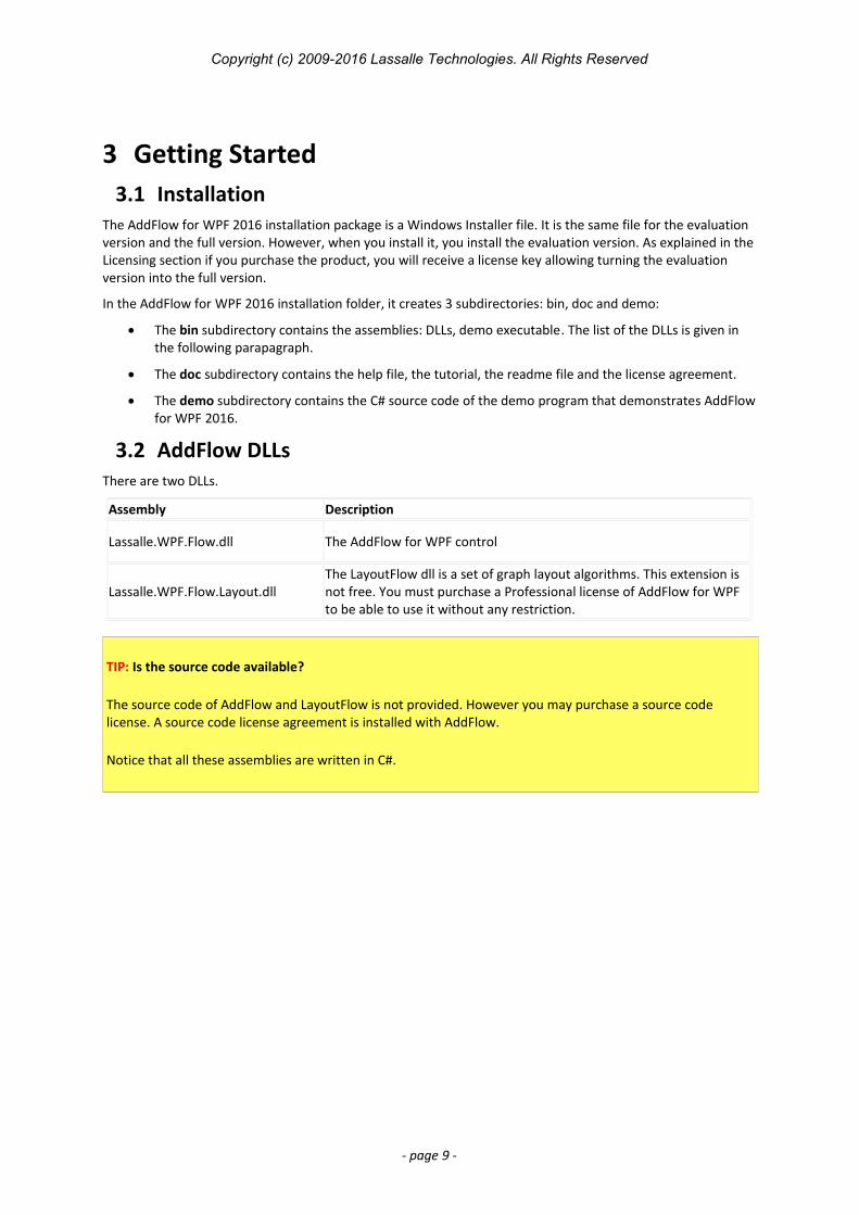
3.2 AddFlow DLLsThere are two DLLs.
Assembly Description
Lassalle.WPF.Flow.dll The AddFlow for WPF control
Lassalle.WPF.Flow.Layout.dllThe LayoutFlow dll is a set of graph layout algorithms. This extension is not free. You must purchase a Professional license of AddFlow for WPF to be able to use it without any restriction.
TIP: Is the source code available?
The source code of AddFlow and LayoutFlow is not provided. However you may purchase a source code license. A source code license agreement is installed with AddFlow.
Notice that all these assemblies are written in C#.
- page 9 -
Copyright (c) 2009-2016 Lassalle Technologies. All Rights Reserved
3.3 Licensing
3.3.1 Key Points
The key points are the following:
each product is licensed per individual developer each product is runtime royalty free the evaluation version of each product has a nag banner. You may use it for up to 30 days for trials and design-time evaluation purposes only. you may purchase either the Standard Edition , either the Professional Edition of AddFlow. The professional version provides also a set of graph layout algorithms. multi-pack discounts available It is also possible to purchase the source code.
3.3.2 Type of licenses
3.3.2.1 Editions
You may purchase either:
an AddFlow for WPF 2016 Standard Edition license. This license does not include LayoutFlow. If you tryto execute a graph layout algorithm, you will face sometimes a nag screen. an AddFlow for WPF 2016 Professional Edition license. This license includes LayoutFlow. You can execute the graph layout algorithms provided by LayoutFlow without any restriction.
3.3.2.2 Multi-pack discounts
We offer the following type of licenses:
Single developer license: allows just one developer Team license: allows 4 developers Site license: allows unlimited developers at a single physical address. Enterprise license: allows all developers of an enterprise
3.3.2.3 Source code
You may also purchase the source code or not. A source code license agreement is installed with AddFlow. This agreement mainly says that you do not have the right to make a competitor product and don't have the right to divulge the code. You may purchase a source code license for AddFlow for WPF Standard Edition or for AddFlowfor WPF Professional Edition. Please note that a source code license for AddFlow for WPF Standard Edition requires the purchaser to own an AddFlow for WPF Standard Edition license and that a source code license for AddFlow for WPF Professional Edition requires the purchaser to own an AddFlow for WPF Professional Edition license.
3.3.3 How it works?
The evaluation version
When you install AddFlow for WPF 2016, you install in fact an evaluation version of AddFlow. (And you install also an evaluation version of LayoutFlow)
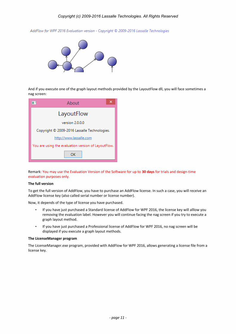
If you generate ("compile") an application that uses this evaluation version of AddFlow for WPF 2016, then any attempt to use this application will display an evaluation label explaining that it has been generated only with an evaluation version of AddFlow.
In the following example, you can see the evaluation label displayed at the top of the diagram.
- page 10 -
Copyright (c) 2009-2016 Lassalle Technologies. All Rights Reserved
And if you execute one of the graph layout methods provided by the LayoutFlow dll, you will face sometimes a nag screen:
Remark: You may use the Evaluation Version of the Software for up to 30 days for trials and design-time evaluation purposes only.
The full version
To get the full version of AddFlow, you have to purchase an AddFlow license. In such a case, you will receive an AddFlow license key (also called serial number or license number).
Now, it depends of the type of license you have purchased.
• If you have just purchased a Standard license of AddFlow for WPF 2016, the license key will alllow you removing the evaluation label. However you will continue facing the nag screen if you try to execute a graph layout method.
• If you have just purchased a Professional license of AddFlow for WPF 2016, no nag screen will be displayed if you execute a graph layout methods.
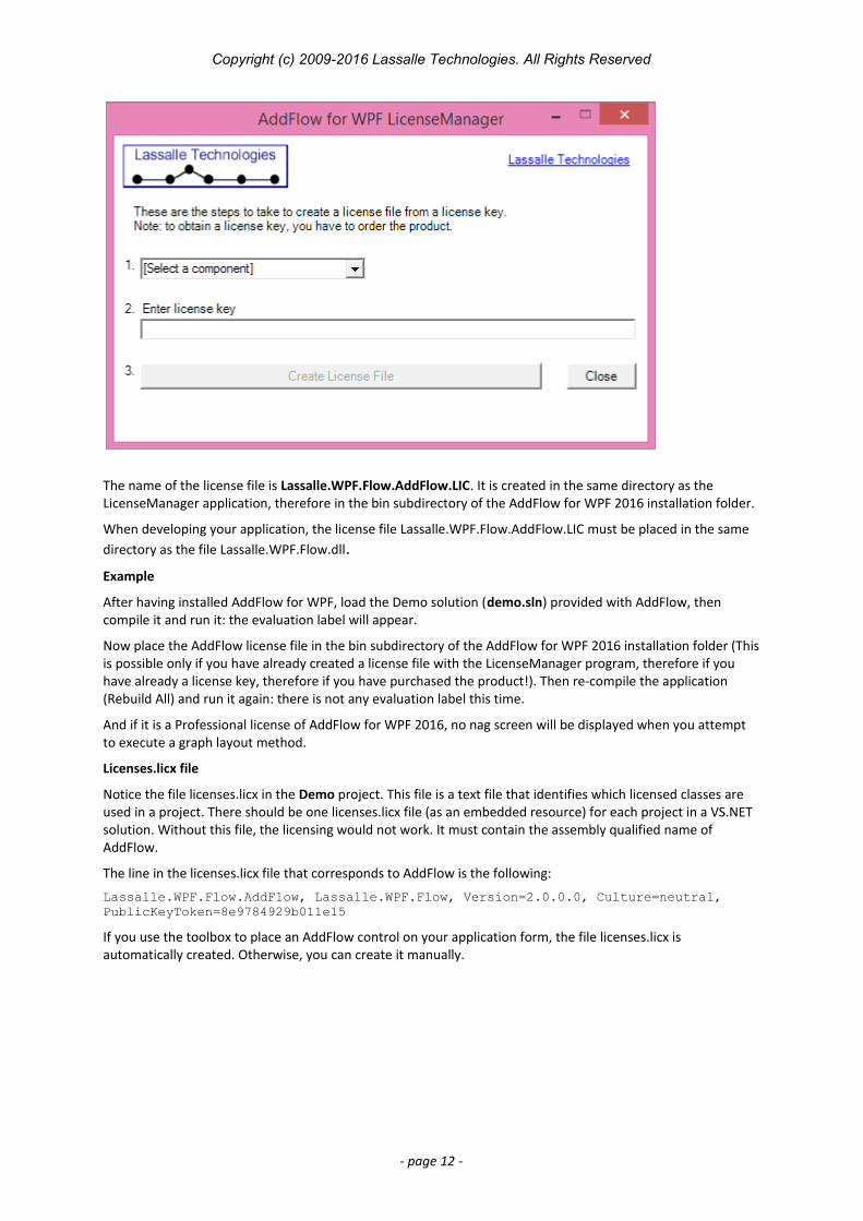
The LicenseManager program
The LicenseManager.exe program, provided with AddFlow for WPF 2016, allows generating a license file from alicense key.
- page 11 -
Copyright (c) 2009-2016 Lassalle Technologies. All Rights Reserved
The name of the license file is Lassalle.WPF.Flow.AddFlow.LIC. It is created in the same directory as the LicenseManager application, therefore in the bin subdirectory of the AddFlow for WPF 2016 installation folder.
When developing your application, the license file Lassalle.WPF.Flow.AddFlow.LIC must be placed in the same directory as the file Lassalle.WPF.Flow.dll.
Example
After having installed AddFlow for WPF, load the Demo solution (demo.sln) provided with AddFlow, then compile it and run it: the evaluation label will appear.
Now place the AddFlow license file in the bin subdirectory of the AddFlow for WPF 2016 installation folder (Thisis possible only if you have already created a license file with the LicenseManager program, therefore if you have already a license key, therefore if you have purchased the product!). Then re-compile the application (Rebuild All) and run it again: there is not any evaluation label this time.
And if it is a Professional license of AddFlow for WPF 2016, no nag screen will be displayed when you attempt to execute a graph layout method.
Licenses.licx file
Notice the file licenses.licx in the Demo project. This file is a text file that identifies which licensed classes are used in a project. There should be one licenses.licx file (as an embedded resource) for each project in a VS.NET solution. Without this file, the licensing would not work. It must contain the assembly qualified name of AddFlow.
The line in the licenses.licx file that corresponds to AddFlow is the following:
Lassalle.WPF.Flow.AddFlow, Lassalle.WPF.Flow, Version=2.0.0.0, Culture=neutral, PublicKeyToken=8e9784929b011e15
If you use the toolbox to place an AddFlow control on your application form, the file licenses.licx is automatically created. Otherwise, you can create it manually.
- page 12 -
Copyright (c) 2009-2016 Lassalle Technologies. All Rights Reserved
4 Interactive creation of a diagram4.1 Overview
It includes:
• the creation of items (nodes, links, captions)
• the selection of items (including multi-selection)
• the resizing of nodes or captions
• the moving of nodes or captions
• the rotation of nodes
• the stretching of links (the possibility to add or remove segments in a link)
• the possibility to change the origin or the destination of a link
• In place edition for nodes or captions.
It supports also the scrolling of diagrams and the use of grids.
Moreover, many properties allow customizing the interactive behavior of an AddFlow control. For instance, youcan prevent the user to create reflexive links with the CanReflexLink property or to move nodes with the CanMoveItems properties.
And a set of methods and properties allow implementing a powerful Undo/Redo feature.
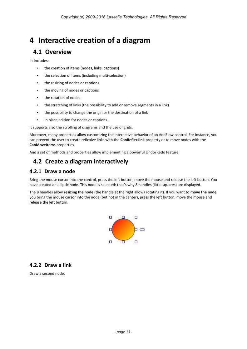
4.2 Create a diagram interactively4.2.1 Draw a nodeBring the mouse cursor into the control, press the left button, move the mouse and release the left button. Youhave created an elliptic node. This node is selected: that's why 8 handles (little squares) are displayed.
The 8 handles allow resizing the node (the handle at the right allows rotating it). If you want to move the node,you bring the mouse cursor into the node (but not in the center), press the left button, move the mouse and release the left button.
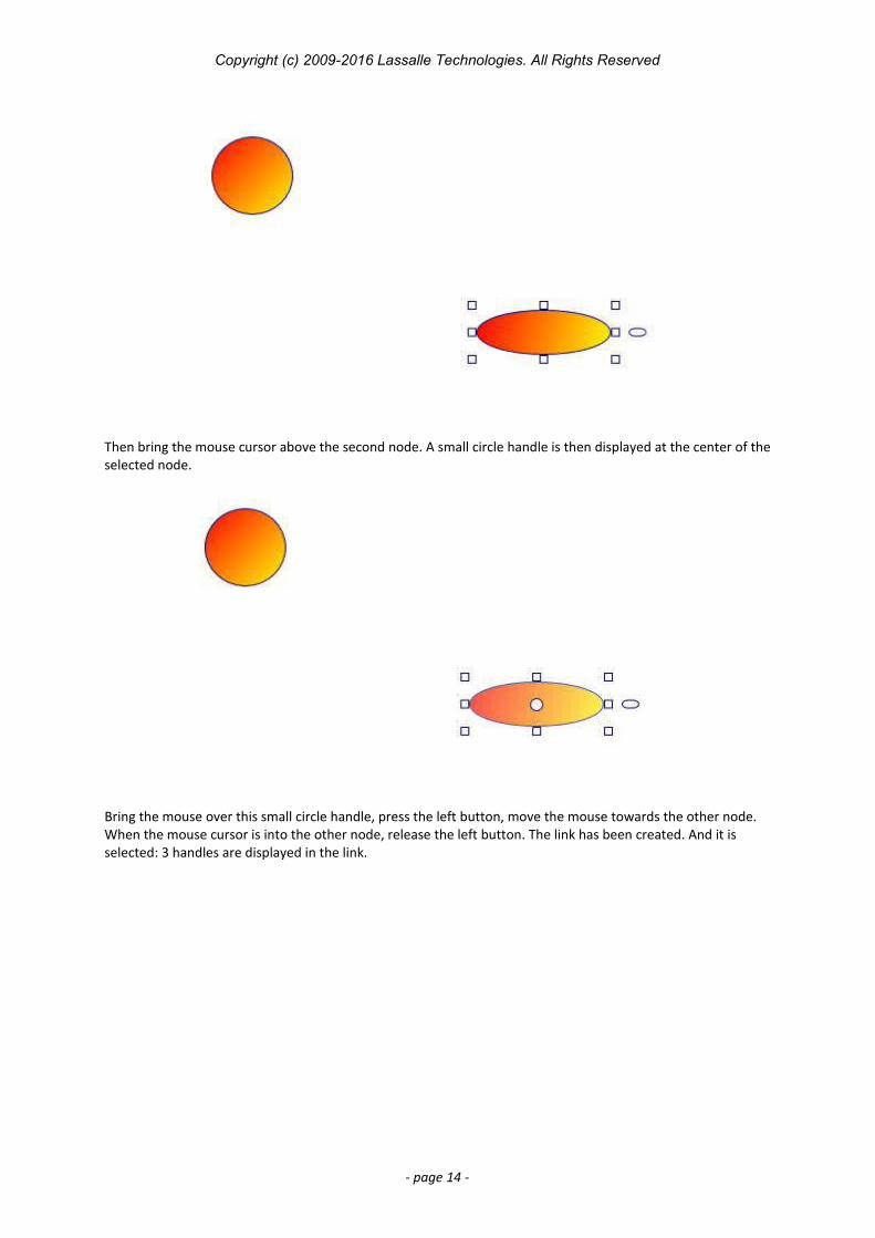
4.2.2 Draw a linkDraw a second node.
- page 13 -
Copyright (c) 2009-2016 Lassalle Technologies. All Rights Reserved
Then bring the mouse cursor above the second node. A small circle handle is then displayed at the center of theselected node.
Bring the mouse over this small circle handle, press the left button, move the mouse towards the other node. When the mouse cursor is into the other node, release the left button. The link has been created. And it is selected: 3 handles are displayed in the link.
- page 14 -
Copyright (c) 2009-2016 Lassalle Technologies. All Rights Reserved
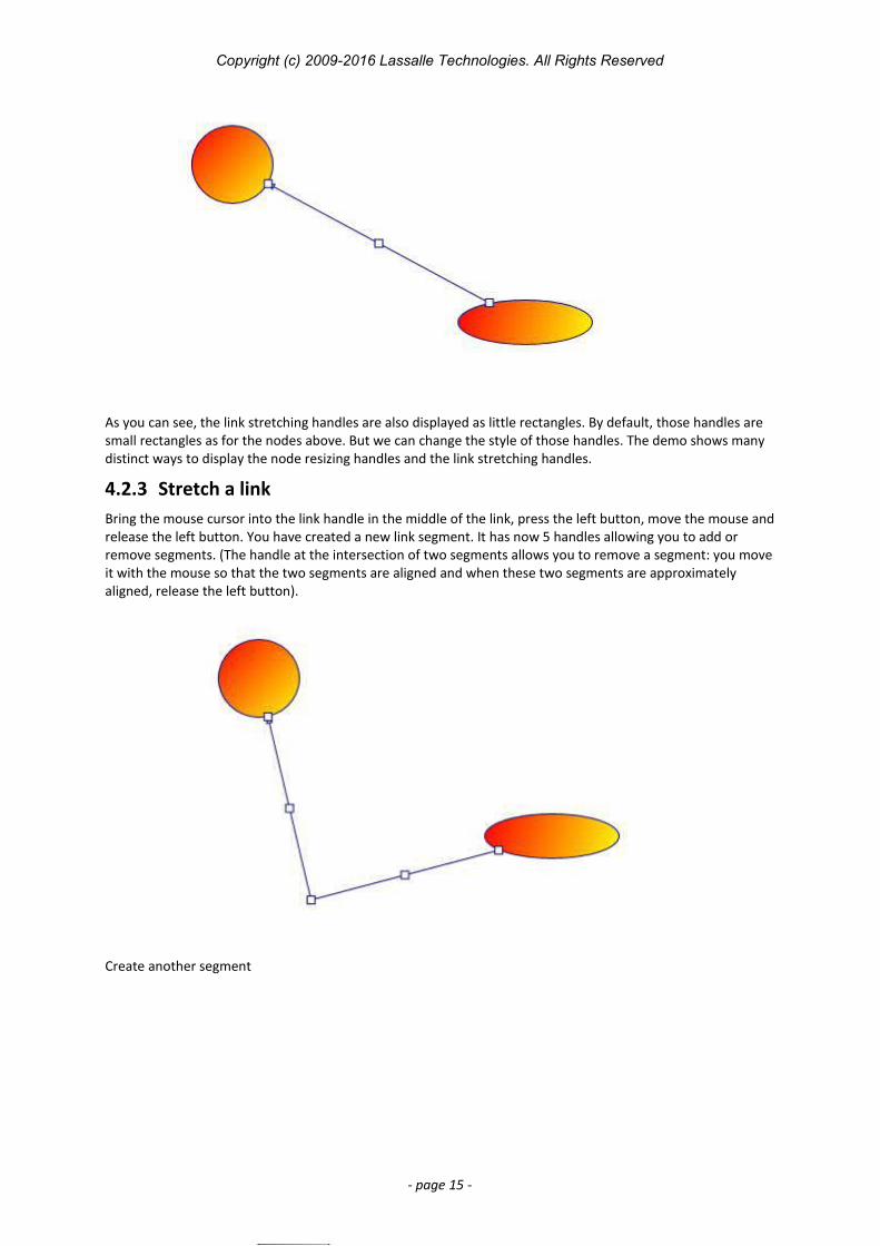
As you can see, the link stretching handles are also displayed as little rectangles. By default, those handles are small rectangles as for the nodes above. But we can change the style of those handles. The demo shows many distinct ways to display the node resizing handles and the link stretching handles.
4.2.3 Stretch a linkBring the mouse cursor into the link handle in the middle of the link, press the left button, move the mouse andrelease the left button. You have created a new link segment. It has now 5 handles allowing you to add or remove segments. (The handle at the intersection of two segments allows you to remove a segment: you moveit with the mouse so that the two segments are aligned and when these two segments are approximately aligned, release the left button).
Create another segment
- page 15 -
Copyright (c) 2009-2016 Lassalle Technologies. All Rights Reserved
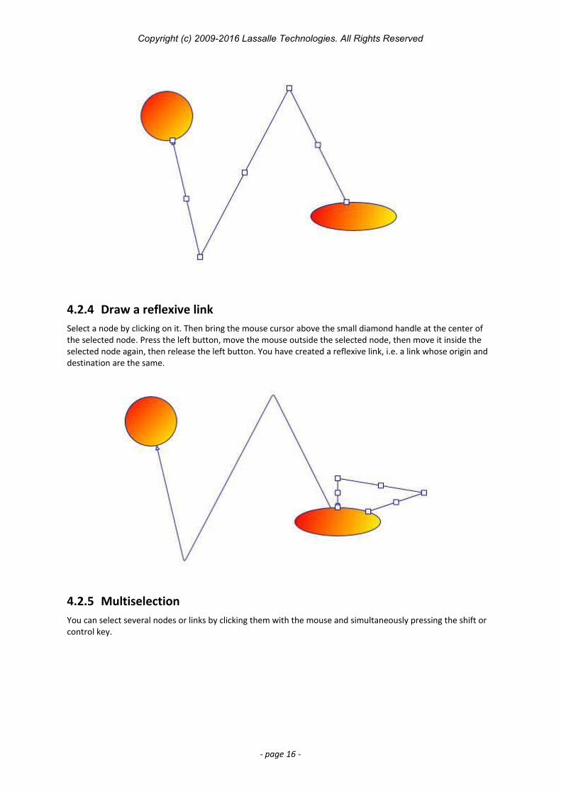
4.2.4 Draw a reflexive linkSelect a node by clicking on it. Then bring the mouse cursor above the small diamond handle at the center of the selected node. Press the left button, move the mouse outside the selected node, then move it inside the selected node again, then release the left button. You have created a reflexive link, i.e. a link whose origin and destination are the same.
4.2.5 MultiselectionYou can select several nodes or links by clicking them with the mouse and simultaneously pressing the shift or control key.
- page 16 -
Copyright (c) 2009-2016 Lassalle Technologies. All Rights Reserved
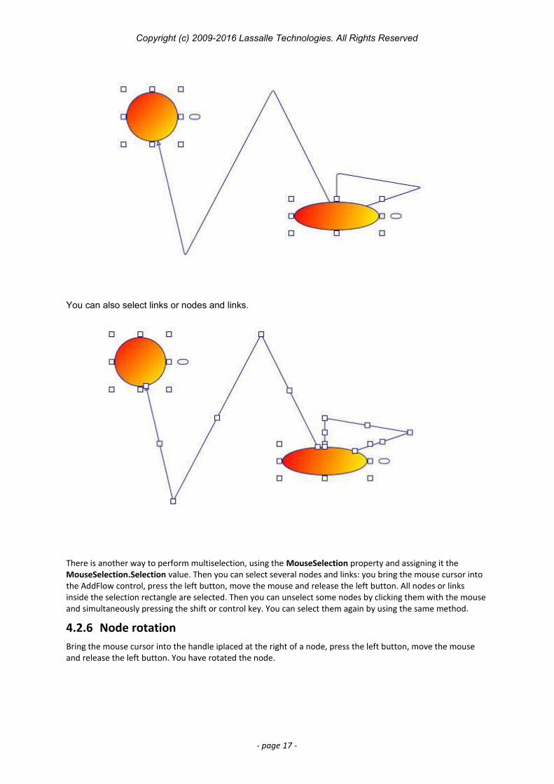
You can also select links or nodes and links.
There is another way to perform multiselection, using the MouseSelection property and assigning it the MouseSelection.Selection value. Then you can select several nodes and links: you bring the mouse cursor into the AddFlow control, press the left button, move the mouse and release the left button. All nodes or links inside the selection rectangle are selected. Then you can unselect some nodes by clicking them with the mouse and simultaneously pressing the shift or control key. You can select them again by using the same method.
4.2.6 Node rotationBring the mouse cursor into the handle iplaced at the right of a node, press the left button, move the mouse and release the left button. You have rotated the node.
- page 17 -
Copyright (c) 2009-2016 Lassalle Technologies. All Rights Reserved
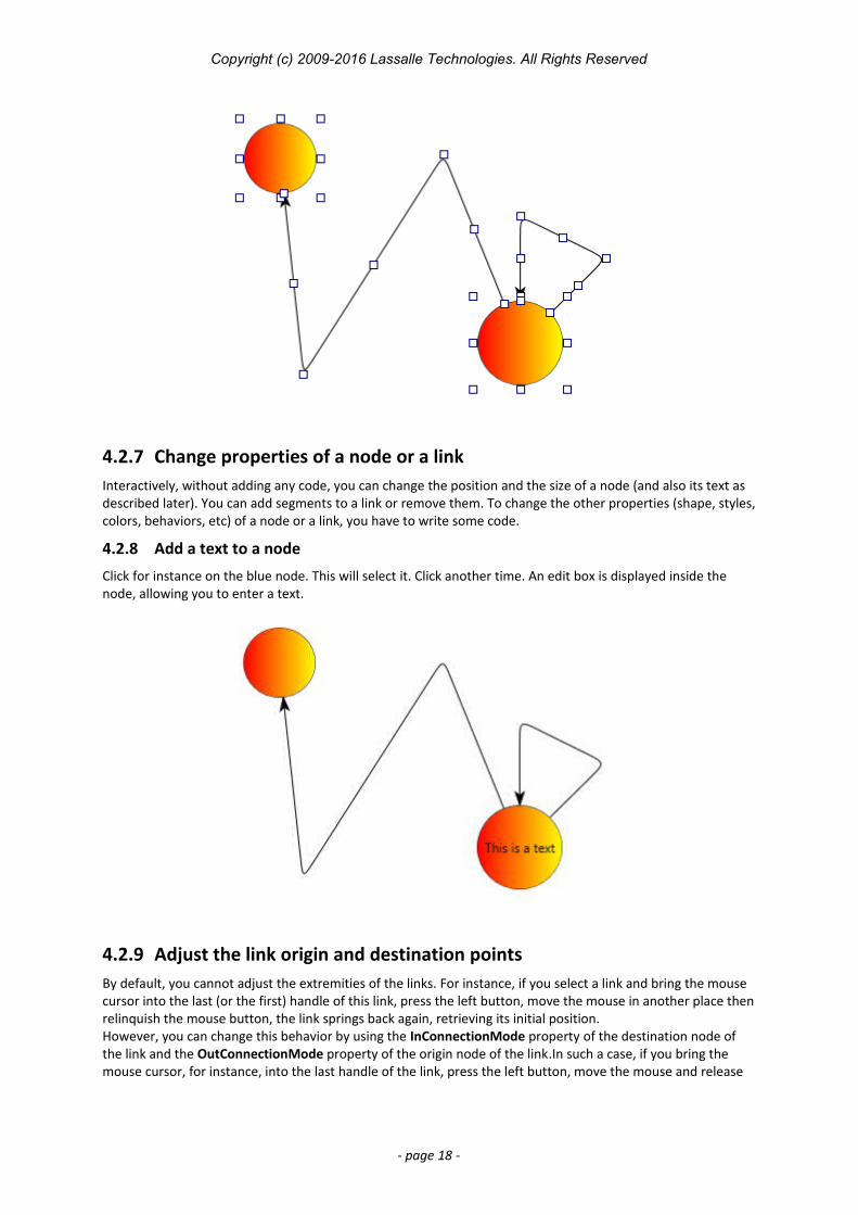
4.2.7 Change properties of a node or a linkInteractively, without adding any code, you can change the position and the size of a node (and also its text as described later). You can add segments to a link or remove them. To change the other properties (shape, styles,colors, behaviors, etc) of a node or a link, you have to write some code.
4.2.8 Add a text to a node
Click for instance on the blue node. This will select it. Click another time. An edit box is displayed inside the node, allowing you to enter a text.
4.2.9 Adjust the link origin and destination pointsBy default, you cannot adjust the extremities of the links. For instance, if you select a link and bring the mouse cursor into the last (or the first) handle of this link, press the left button, move the mouse in another place thenrelinquish the mouse button, the link springs back again, retrieving its initial position.However, you can change this behavior by using the InConnectionMode property of the destination node of the link and the OutConnectionMode property of the origin node of the link.In such a case, if you bring the mouse cursor, for instance, into the last handle of the link, press the left button, move the mouse and release
- page 18 -
Copyright (c) 2009-2016 Lassalle Technologies. All Rights Reserved
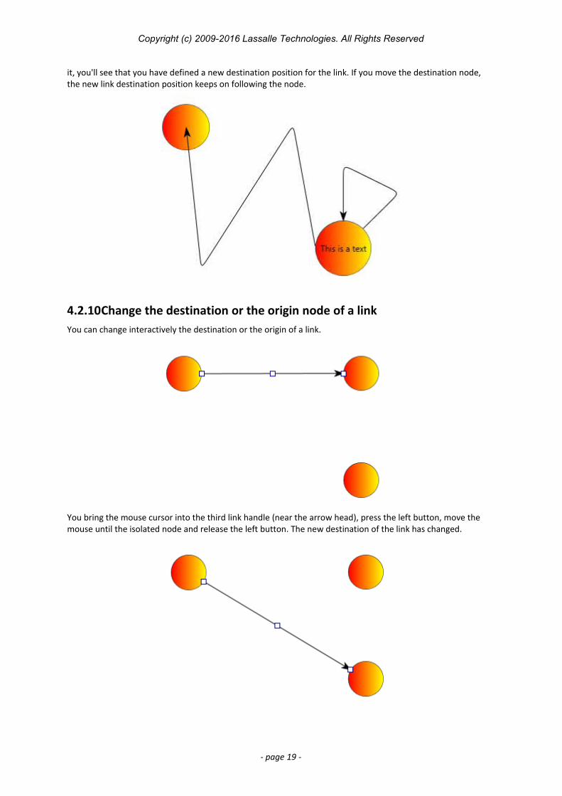
it, you'll see that you have defined a new destination position for the link. If you move the destination node, the new link destination position keeps on following the node.
4.2.10Change the destination or the origin node of a linkYou can change interactively the destination or the origin of a link.
You bring the mouse cursor into the third link handle (near the arrow head), press the left button, move the mouse until the isolated node and release the left button. The new destination of the link has changed.
- page 19 -
Copyright (c) 2009-2016 Lassalle Technologies. All Rights Reserved
5 Programmatic creation of a diagram5.1 Overview
In this chapter we will focus on how to create a diagram programmatically.
The AddFlow library is a .NET class library containing a set of classes for creating interactive diagrams very easily.
The main class is the AddFlow class that derives from the Canvas class. It contains a DrawingVisual object that which is used to display the diagram. The Visual property returns this DrawingVisual object.
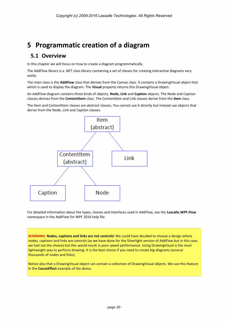
An AddFlow diagram contains three kinds of objects, Node, Link and Caption objects. The Node and Caption classes derives from the ContentItem class. The ContentItem and Link classes derive from the Item class.
The Item and ContentItem classes are abstract classes. You cannot use it directly but instead use objects that derive from the Node, Link and Caption classes.
For detailed information about the types, classes and interfaces used in AddFlow, see the Lassalle.WPF.Flow namespace in the AddFlow for WPF 2016 help file.
WARNING: Nodes, captions and links are not controls! We could have decided to choose a design where nodes, captions and links are controls (as we have done for the Silverlight version of AddFlow but in this case, we had not the choice) but this would result in poor speed performance. Using DrawingVisual is the most lightweight way to perform drawing. It is the best choice if you need to create big diagrams (several thousands of nodes and links).
Notice also that a DrawingVisual object can contain a collection of DrawingVisual objects. We use this feature in the CauseEffect example of the demo.
- page 20 -
Copyright (c) 2009-2016 Lassalle Technologies. All Rights Reserved
5.2 AddFlow Items
5.2.1 ItemThe Item class represents an item in the diagram. All classes representing diagram elements derive from Item.
The main purpose is to provide common methods and properties of every diagram element: nodes, links, captions.
Note that it is an abstract class. You cannot use it directly but instead use objects that derive from the Node, Link or Caption classes.
The Item class provides some style properties, data properties and behavior properties used by all the items of an AddFlow diagram.
Style properties
The Fill, Stroke properties allow defining item colors. The Font property allows defining the font used to display the text associated to the item. The DashStyle, StrokeThickness, IsOwnerDraw properties allows defining how the item is displayed.
Data properties
The Text property defines the string displayed inside or near the item. The Tooltip property defines the tooltip of the item.
Behaviour properties
IsSelected, IsHitTestVisible, IsSelectable.
5.2.2 ContentItemA ContentItem object is an Item object that has a content which may be a string or/and an image. Nodes and captions are ContentItem objects.
The main purpose is to provide common methods and properties for nodes and captions. Note that it is an abstract class. You cannot use it directly but instead use objects that derive from Node or Caption classes.
The Location, Size, RotationAngle properties allow getting or setting the location, size and rotation of a ContentItem object.
The Geometry property allow getting ang setting the shape of the ContentItem object.
The TextPosition, TextMargin, ImagePosition, ImageMargin properties determine how the text and the image are positioned in the ContentItem object.
The IsXMoveable, IsYMoveable, IsXSizeable, IsYSizeable properties determine if the ContentItem object can be moved or resized.
The IsEditable properties determine if “in place” edition is possible in the ContentItem object.
5.2.3 Node A node (also called vertice or entity) is a ContentItem object that can be linked to another node.
The Node class provides the Links collection property that allows getting all the links of the node.
The IsInLinkable and IsOutLinkable boolean properties determine if “in” or “out” links are allowed.
5.2.4 Link A link (also called edge, relation or arc) is an Item object allowing linking two nodes. It is a line that leaves the origin node and comes to the destination node. A link cannot exist without its origin and destination nodes. If one of these two nodes is removed, the link is also removed.
The Org and Dst properties allow getting or setting the origin and destination node of the link.
The PinOrgIndex and PinDstIndex properties allow getting or setting the origin pin index and the destination pin index of the link.
- page 21 -
Copyright (c) 2009-2016 Lassalle Technologies. All Rights Reserved
The Points property is the collection of points that define the segments of the link.
The LineStyle property defines the style of link (polyline, Bezier, Spline, orthogonal)
The IsArrowOrg, IsArrowDst and IsArrowMid properties define if arrows are used for the link.
The ArrowOrg, ArrowDst and ArrowMid properties define the arrow shape.
The JumpSize property determines the size of the jump displayed at the intersection of 2 links.
The RoundCornerSize property determines the size of the rounded corners of the link segments.
The IsOrientedText property determines whether the link text can be drawn in the same direction as the link itself.
The IsStretchable property determines whether the link is stretchable or not. When a link is not stretchable, the user cannot interactively stretch it with the mouse.
The IsAdjustDst and IsAdjustOrg properties determinesvwhether it is possible to adjust the position of the last and first point of the link.
5.2.5 CaptionA caption (also called label or note) is a ContentItem object that can be owned by an AddFlow item, therefore by a node, a link or even by another caption.
The Caption class provides the Owner property that allows getting and setting the owner of the caption.
The Dock property returns/sets the DockStyle of the caption. This property is relevant only if the caption is attached to a ContentItem object.
The AnchorPositionOnLink property returns/sets a value which defines the position of the caption near the link. This property is relevant only if the caption is attached to a link.
5.3 Collections of items
AddFlow provide the following collections: Items: the collection of all items of the diagram SelectedItems: collection of all selected items of the diagram Links: collection of all links (in and out) of a node Captions: collection of captions of an AddFlow item.
WARNING: Those collections are provided for only for the AddFlow infrastructure and for enumeration purposes. Don't use them for adding or removing items.
5.4 Creation and deletion of items
5.4.1 NodeTo add a node to a diagram, you have first to instanciate it then use the AddNode method to add it to the diagram. To remove it, you call the RemoveNode method.
The Node class has 3 constructors.
Node constructorsNode() Node(float left, float top, float width, float height, string text, AddFlow addflow)Node(float left, float top, float width, float height, string text, Node node)
- page 22 -
Copyright (c) 2009-2016 Lassalle Technologies. All Rights Reserved
We will often use the second constructor that creates a node with an initial position, an initial size, an initial text displayed inside the node and a reference to the AddFlow control that will supply default property values for the node.
The third constructor is working as the second one except that the default property values are copied from a node model.
5.4.2 LinkTo add a link to a diagram, you have first to instanciate it then use the AddLink method to add it to the diagram. To remove it, you call the RemoveLink method.
The Link class has 5 constructors.
Link constructorsLink() Link(Node org, Node dst, string text, Link link)Link(Node org, Node dst, int pinOrgIndex, int pinDstIndex, string text, Link link)Link(Node org, Node dst, string text, AddFlow addflow)Link(Node org, Node dst, int pinOrgIndex, int pinDstIndex, string text, AddFlow addflow)
As for nodes, to supply default property values for the link, you can use a reference to the AddFlow control or use a link model.
5.4.3 CaptionTo add a caption to a diagram, you have first to instanciate it then use the AddCaption method to add it to the diagram. To remove it, you call the RemoveCaption method.
The Caption class has 3 constructors.
Caption constructorsCaption() Caption(float left,float top,float width,float height,string text,Item owner, AddFlow addflow)Caption(float left,float top,float width,float height,string text,Item owner, Caption caption)
We will often use the second constructor that creates a caption with an initial position, an initial size, an initial text displayed inside the caption, a reference to the owner item of this caption and a reference to the AddFlow control that will supply default property values for the node.
The third constructor is working as the second one except that the default property values are copied from a caption model.
5.5 Diagram creation
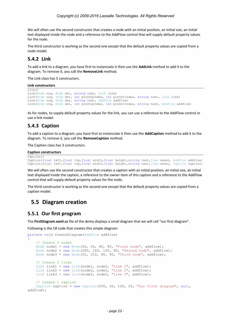
5.5.1 Our first programThe FirstDiagram.xaml.cs file of the demo displays a small diagram that we will call “our first diagram”.
Following is the C# code that creates this simple diagram:
private void CreateDiagram(AddFlow addflow){ // Create 3 nodes Node node1 = new Node(50, 50, 80, 80, "First node", addflow); Node node2 = new Node(280, 160, 100, 80, "Second node", addflow); Node node3 = new Node(50, 210, 80, 80, "Third node", addflow); // Create 3 links Link link1 = new Link(node1, node2, "link 1", addflow); Link link2 = new Link(node2, node2, "link 2", addflow); Link link3 = new Link(node2, node3, "link 3", addflow);
// Create 1 caption Caption caption = new Caption(200, 30, 100, 20, "Our first diagram", null, addflow);
- page 23 -
Copyright (c) 2009-2016 Lassalle Technologies. All Rights Reserved
// Add the items to the diagram addflow.AddNode(node1); addflow.AddNode(node2); addflow.AddNode(node3); addflow.AddLink(link1); addflow.AddLink(link2); addflow.AddLink(link3); addflow.AddCaption(caption); }
This code creates the following diagram:
In this diagram, the nodes and links receive default property values. For instance, the nodes have an elliptical shape. The links are composed of one line terminated by an arrow. The link 2 is reflexive and by default, it is created with 3 segments. The drawing color is black. The text color is black.
We are going to enhance this diagram. However, let us focus on the way nodes, links and captions are created. First we create objects, then we add them to the AddFlow control. If we just write:
Node node1 = new Node(50, 50, 80, 80, "First node", addflow);
the node object is created. However it is not still part of the diagram. To make this node belong to the diagram,we have to add the following line:
addflow.AddNode(node1);
Same thing for links: if we just write:
Link link1 = new Link(node1, node2, "link 1", addflow);
the link object is created. However, to give a true existence to this link, we have to add the following line:
addflow.AddLink(link1);
5.5.2 Other ways to create the diagramWe could have written this first program in the following manner:
void CreateDiagram2(AddFlow addflow){ // Create and add the nodes to the diagram addflow.AddNode(new Node(50, 50, 80, 80, "First node", addflow)); addflow.AddNode(new Node(280, 160, 100, 80, "Second node", addflow)); addflow.AddNode(new Node(50, 210, 80, 80, "Third node", addflow));
// We use LINQ to select in an array all the nodes of the canvas. var nodes = addflow.Items.OfType<Node>().ToArray();
// Create and add the links to the diagram addflow.AddLink(new Link(nodes[0], nodes[1], "link 1", addflow)); addflow.AddLink(new Link(nodes[1], nodes[1], "link 2", addflow)); addflow.AddLink(new Link(nodes[1], nodes[2], "link 3", addflow));
addflow.AddCaption(new Caption(200, 30, 100, 20, "Our first diagram", null, addflow));}
In this case, we use a nodes collection created with LINQ instead of using a reference for each Node object.
We could also use helpers functions to create nodes and links, as in the following CreateDiagram3 function where we use the helpers functions AddNode and AddLink.
void CreateDiagram3(AddFlow addflow){ // Create and add the nodes to the diagram Node node1 = this.AddNode(addflow, 50, 50, 80, 80, "First node"); Node node2 = this.AddNode(addflow, 280, 160, 100, 80, "Second node"); Node node3 = this.AddNode(addflow, 50, 210, 80, 80, "Third node");
- page 24 -
Copyright (c) 2009-2016 Lassalle Technologies. All Rights Reserved
// Create and add the links to the diagram this.AddLink(addflow, node1, node2, "link 1"); this.AddLink(addflow, node2, node2, "link 2"); this.AddLink(addflow, node2, node3, "link 3");
// Create and a caption to the diagram this.AddCaption(addflow, 200, 30, 100, 20, "Our first diagram", null);}
Node AddNode(AddFlow addflow, float left, float top, float width, float height, string text){ Node node = new Node(left, top, width, height, text, addflow); addflow.AddNode(node); return node;}
Link AddLink(AddFlow addflow, Node org, Node dst, string text){ Link link = new Link(org, dst, text, addflow); addflow.AddLink(link); return link;}
Caption AddCaption(AddFlow addflow, double left, double top, double width, double height, string text, Item owner){ Caption caption = new Caption(left, top, width, height, text, owner, addflow); addflow.AddCaption(caption); return caption;}
In the Demo sample, we often use this kind of helpers functions.
Now we are going to enhance our diagram.
5.5.3 Changing property valuesNow let us include the following “using” statement (it can be found in the demo)
using Lassalle.WPF.Geometries;
and let us use the following diagram creation method (ItemsProperties.xaml.cs file of the demo):
private void CreateDiagram(AddFlow addflow){ // Create 3 yellow nodes with a shadow. // The second node is rectangular // and the third one has a Document shape style. Node node1 = new Node(50, 50, 80, 80, "First node", addflow); node1.Fill = Brushes.LightYellow;
Node node2 = new Node(280, 160, 100, 80, "Second node", addflow); node2.Fill = Brushes.LightYellow; node2.Geometry = new RectangleGeometry(new Rect(0, 0, 64, 64));
Node node3 = new Node(50, 210, 80, 80, "Third node", addflow); node3.Fill = Brushes.LightYellow; node3.Geometry = Geometry.Parse("M 0,0 H 60 V 40 C 30,30 30,50 0,40 Z");
// Create 3 links. // Each link is blue and its BackMode property set to Opaque. // The second link has a Bezier style, color of its text is red, and // its destination arrow head angle is 30°. // The third link has a “HVH” style. Link link1 = new Link(node1, node2, "link 1", addflow); link1.Stroke = Brushes.Blue; link1.Foreground = Brushes.Red; Link link2 = new Link(node2, node2, "link 2", addflow);
- page 25 -
Copyright (c) 2009-2016 Lassalle Technologies. All Rights Reserved
link2.Stroke = Brushes.Blue; link2.LineStyle = LineStyle.Bezier; link2.Foreground = Brushes.Red; link2.ArrowGeometryDst = Geometry.Parse("M0,0 8,4 0,8 Z");
Link link3 = new Link(node2, node3, "link 3", addflow); link3.Stroke = Brushes.Blue; link3.LineStyle = LineStyle.Orthogonal; link3.ArrowGeometryDst = Geometry.Parse("M3,4 L0,0 12,4 0,8 z");
// Create 1 caption Caption caption = new Caption(200, 30, 220, 20, "Node and link properties", null, addflow); caption.Foreground = Brushes.Blue; caption.Stroke = Brushes.Transparent; caption.FontSize = 14;
// Add the nodes and the links to the diagram addflow.AddNode(node1); addflow.AddNode(node2); addflow.AddNode(node3); addflow.AddLink(link1); addflow.AddLink(link2); addflow.AddLink(link3); addflow.AddCaption(caption);
node1.Visual.Effect = this.dse; node2.Visual.Effect = this.dse; node3.Visual.Effect = this.dse;}
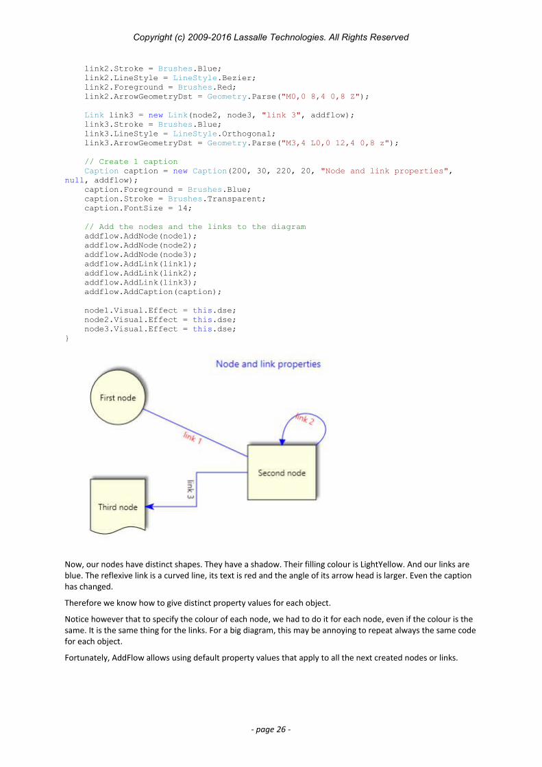
Now, our nodes have distinct shapes. They have a shadow. Their filling colour is LightYellow. And our links are blue. The reflexive link is a curved line, its text is red and the angle of its arrow head is larger. Even the caption has changed.
Therefore we know how to give distinct property values for each object.
Notice however that to specify the colour of each node, we had to do it for each node, even if the colour is the same. It is the same thing for the links. For a big diagram, this may be annoying to repeat always the same codefor each object.
Fortunately, AddFlow allows using default property values that apply to all the next created nodes or links.
- page 26 -
Copyright (c) 2009-2016 Lassalle Technologies. All Rights Reserved
TIP: In the previous examples, to define a node geometry or a link arrow geometry, we have used the PathGeometry Markup Syntax. For instance:
node.Geometry = Geometry.Parse("M 0,0 H 60 V 40 C 30,30 30,50 0,40 Z");
However, this method, although elegant, has also its drawbacks. We will see later another method that uses the PredefinedGeometry class used in the demo.
5.5.4 Default property valuesNow, let us use the following diagram creation method (DefaultProperties.xaml.cs file of the demo):
private void CreateDiagram(AddFlow addflow){ // Assign default property values for nodes and links addflow.NodeModel.Fill = Brushes.LightYellow; addflow.LinkModel.Stroke = Brushes.Blue; addflow.LinkModel.Foreground = Brushes.Red;
// Create 3 yellow nodes with a shadow. // The second node is rectangular // and the third one has a Document shape style. Node node1 = new Node(50, 50, 80, 80, "First node", addflow);
Node node2 = new Node(280, 160, 100, 80, "Second node", addflow); node2.Geometry = new RectangleGeometry(new Rect(0, 0, 64, 64));
Node node3 = new Node(50, 210, 80, 80, "Third node", addflow); node3.Geometry = Geometry.Parse("M 0,0 H 60 V 40 C 30,30 30,50 0,40 Z");
// Create 3 links. // Each link is blue and its BackMode property set to Opaque. // The second link has a Bezier style, color of its text is red, and // its destination arrow head angle is 30°. // The third link has a “HVH” style. Link link1 = new Link(node1, node2, "link 1", addflow); Link link2 = new Link(node2, node2, "link 2", addflow); link2.LineStyle = LineStyle.Bezier; link2.ArrowGeometryDst = Geometry.Parse("M0,0 8,4 0,8 Z");
Link link3 = new Link(node2, node3, "link 3", addflow); link3.LineStyle = LineStyle.Orthogonal; link3.ArrowGeometryDst = Geometry.Parse("M3,4 L0,0 12,4 0,8 z");
// Create 1 caption Caption caption = new Caption(200, 30, 220, 20, "Default properties", null, addflow); caption.Foreground = Brushes.Blue; caption.Stroke = Brushes.Transparent; caption.FontSize = 14;
// Add the nodes and the links to the diagram addflow.AddNode(node1); addflow.AddNode(node2); addflow.AddNode(node3); addflow.AddLink(link1); addflow.AddLink(link2); addflow.AddLink(link3); addflow.AddCaption(caption);
node1.Visual.Effect = this.dse; node2.Visual.Effect = this.dse;
- page 27 -
Copyright (c) 2009-2016 Lassalle Technologies. All Rights Reserved
node3.Visual.Effect = this.dse;}
This new program will create the same diagram. it will create the same diagram. However, our program is smaller because we have used the NodeModel, CaptionModel and the LinkModel properties of AddFlow which allow specifying default property values for nodes and links. For instance, writing:
addflow.NodeModel.Fill = Brushes.LightYellow;
indicates that all the nodes that will be created after will be filled with a LightYellow color.
Then you just need to specify the property values that differ from the defaults.
Notice that the NodeModel, CaptionModel and the LinkModel properties have also an interactive effect. Not only the nodes created programmatically will be filled with a LightYellow colour but also the nodes created interactively with the mouse. This may be interesting or not, depending on what you intend to do.
Anyway, it is also possible to specify default values when creating a diagram programmatically and have other default values for the interactive creation.
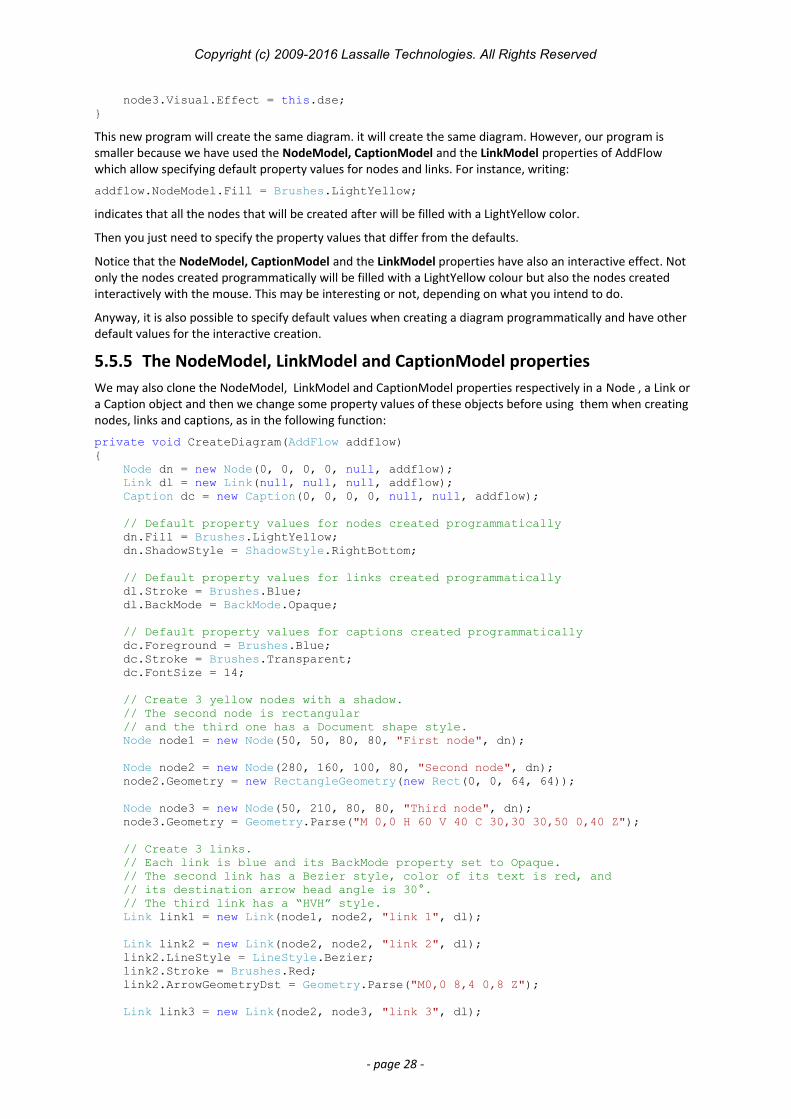
5.5.5 The NodeModel, LinkModel and CaptionModel propertiesWe may also clone the NodeModel, LinkModel and CaptionModel properties respectively in a Node , a Link or a Caption object and then we change some property values of these objects before using them when creating nodes, links and captions, as in the following function:
private void CreateDiagram(AddFlow addflow){ Node dn = new Node(0, 0, 0, 0, null, addflow); Link dl = new Link(null, null, null, addflow); Caption dc = new Caption(0, 0, 0, 0, null, null, addflow);
// Default property values for nodes created programmatically dn.Fill = Brushes.LightYellow; dn.ShadowStyle = ShadowStyle.RightBottom;
// Default property values for links created programmatically dl.Stroke = Brushes.Blue; dl.BackMode = BackMode.Opaque;
// Default property values for captions created programmatically dc.Foreground = Brushes.Blue; dc.Stroke = Brushes.Transparent; dc.FontSize = 14;
// Create 3 yellow nodes with a shadow. // The second node is rectangular // and the third one has a Document shape style. Node node1 = new Node(50, 50, 80, 80, "First node", dn);
Node node2 = new Node(280, 160, 100, 80, "Second node", dn); node2.Geometry = new RectangleGeometry(new Rect(0, 0, 64, 64));
Node node3 = new Node(50, 210, 80, 80, "Third node", dn); node3.Geometry = Geometry.Parse("M 0,0 H 60 V 40 C 30,30 30,50 0,40 Z");
// Create 3 links. // Each link is blue and its BackMode property set to Opaque. // The second link has a Bezier style, color of its text is red, and // its destination arrow head angle is 30°. // The third link has a “HVH” style. Link link1 = new Link(node1, node2, "link 1", dl);
Link link2 = new Link(node2, node2, "link 2", dl); link2.LineStyle = LineStyle.Bezier; link2.Stroke = Brushes.Red; link2.ArrowGeometryDst = Geometry.Parse("M0,0 8,4 0,8 Z");
Link link3 = new Link(node2, node3, "link 3", dl);
- page 28 -
Copyright (c) 2009-2016 Lassalle Technologies. All Rights Reserved
link3.LineStyle = LineStyle.Orthogonal;
// Create 1 caption Caption caption = new Caption(200, 30, 220, 20, "Default properties", null, dc);
// Add the nodes and the links to the diagram addflow.AddNode(node1); addflow.AddNode(node2); addflow.AddNode(node3); addflow.AddLink(link1); addflow.AddLink(link2); addflow.AddLink(link3); addflow.AddCaption(caption); }
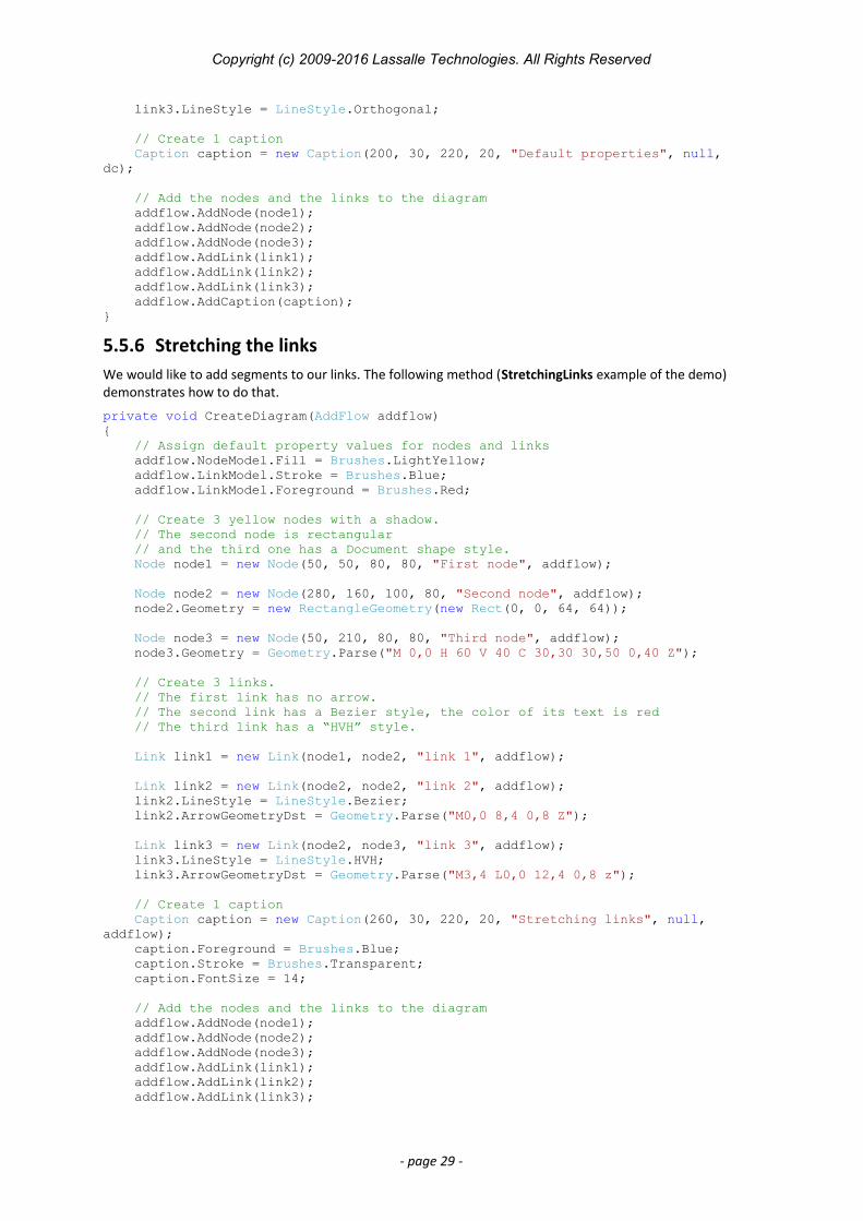
5.5.6 Stretching the linksWe would like to add segments to our links. The following method (StretchingLinks example of the demo) demonstrates how to do that.
private void CreateDiagram(AddFlow addflow){ // Assign default property values for nodes and links addflow.NodeModel.Fill = Brushes.LightYellow; addflow.LinkModel.Stroke = Brushes.Blue; addflow.LinkModel.Foreground = Brushes.Red;
// Create 3 yellow nodes with a shadow. // The second node is rectangular // and the third one has a Document shape style. Node node1 = new Node(50, 50, 80, 80, "First node", addflow);
Node node2 = new Node(280, 160, 100, 80, "Second node", addflow); node2.Geometry = new RectangleGeometry(new Rect(0, 0, 64, 64));
Node node3 = new Node(50, 210, 80, 80, "Third node", addflow); node3.Geometry = Geometry.Parse("M 0,0 H 60 V 40 C 30,30 30,50 0,40 Z");
// Create 3 links. // The first link has no arrow. // The second link has a Bezier style, the color of its text is red // The third link has a “HVH” style.
Link link1 = new Link(node1, node2, "link 1", addflow);
Link link2 = new Link(node2, node2, "link 2", addflow); link2.LineStyle = LineStyle.Bezier; link2.ArrowGeometryDst = Geometry.Parse("M0,0 8,4 0,8 Z");
Link link3 = new Link(node2, node3, "link 3", addflow); link3.LineStyle = LineStyle.HVH; link3.ArrowGeometryDst = Geometry.Parse("M3,4 L0,0 12,4 0,8 z");
// Create 1 caption Caption caption = new Caption(260, 30, 220, 20, "Stretching links", null, addflow); caption.Foreground = Brushes.Blue; caption.Stroke = Brushes.Transparent; caption.FontSize = 14;
// Add the nodes and the links to the diagram addflow.AddNode(node1); addflow.AddNode(node2); addflow.AddNode(node3); addflow.AddLink(link1); addflow.AddLink(link2); addflow.AddLink(link3);
- page 29 -
Copyright (c) 2009-2016 Lassalle Technologies. All Rights Reserved
addflow.AddCaption(caption);
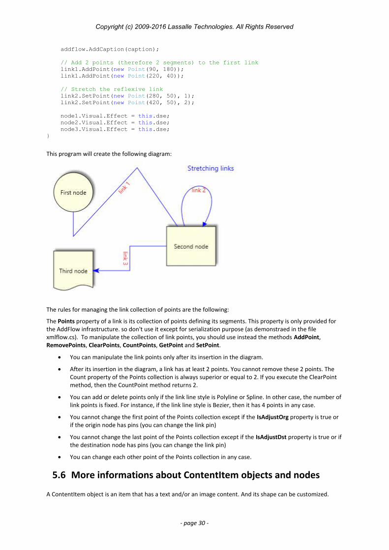
// Add 2 points (therefore 2 segments) to the first link link1.AddPoint(new Point(90, 180)); link1.AddPoint(new Point(220, 40));
// Stretch the reflexive link link2.SetPoint(new Point(280, 50), 1); link2.SetPoint(new Point(420, 50), 2);
node1.Visual.Effect = this.dse; node2.Visual.Effect = this.dse; node3.Visual.Effect = this.dse;}
This program will create the following diagram:
The rules for managing the link collection of points are the following:
The Points property of a link is its collection of points defining its segments. This property is only provided for the AddFlow infrastructure. so don't use it except for serialization purpose (as demonstraed in the file xmlflow.cs). To manipulate the collection of link points, you should use instead the methods AddPoint, RemovePoints, ClearPoints, CountPoints, GetPoint and SetPoint.
You can manipulate the link points only after its insertion in the diagram.
After its insertion in the diagram, a link has at least 2 points. You cannot remove these 2 points. The Count property of the Points collection is always superior or equal to 2. If you execute the ClearPoint method, then the CountPoint method returns 2.
You can add or delete points only if the link line style is Polyline or Spline. In other case, the number oflink points is fixed. For instance, if the link line style is Bezier, then it has 4 points in any case.
You cannot change the first point of the Points collection except if the IsAdjustOrg property is true or if the origin node has pins (you can change the link pin)
You cannot change the last point of the Points collection except if the IsAdjustDst property is true or ifthe destination node has pins (you can change the link pin)
You can change each other point of the Points collection in any case.
5.6 More informations about ContentItem objects and nodes
A ContentItem object is an item that has a text and/or an image content. And its shape can be customized.
- page 30 -
Copyright (c) 2009-2016 Lassalle Technologies. All Rights Reserved
However, only nodes accept pins: we may define for each node a set of pins to connect links.
(Remember that nodes and captions are ContentItem objects.)
5.6.1 ContentItem colors
Three properties allow setting colors for a ContentItem object:
Stroke It is the brush of the ContentItem object border. Fill It is the ContentItem object filling brush. Foreground It is the brush of the ContentItem object text.
TIP: How to make the node's (or caption's) border transparent?
node.Stroke = Brushes.Transparent;
5.6.2 ContentItem object text
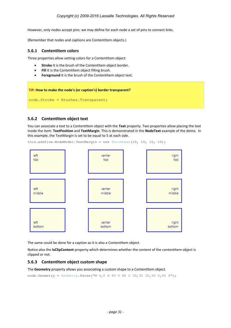
You can associate a text to a ContentItem object with the Text property. Two properties allow placing the text inside the item: TextPosition and TextMargin. This is demonstrated in the NodeText example of the demo. In this example, the TextMargin is set to be equal to 5 at each side.
this.addflow.NodeModel.TextMargin = new Thickness(10, 10, 10, 10);
The same could be done for a caption as it is also a ContentItem object.
Notice also the IsClipContent property which determines whether the content of the contentItem object is clipped or not.
5.6.3 ContentItem object custom shape
The Geometry property allows you associating a custom shape to a ContentItem object.
node.Geometry = Geometry.Parse("M 0,0 H 60 V 40 C 30,30 30,50 0,40 Z");
- page 31 -
Copyright (c) 2009-2016 Lassalle Technologies. All Rights Reserved
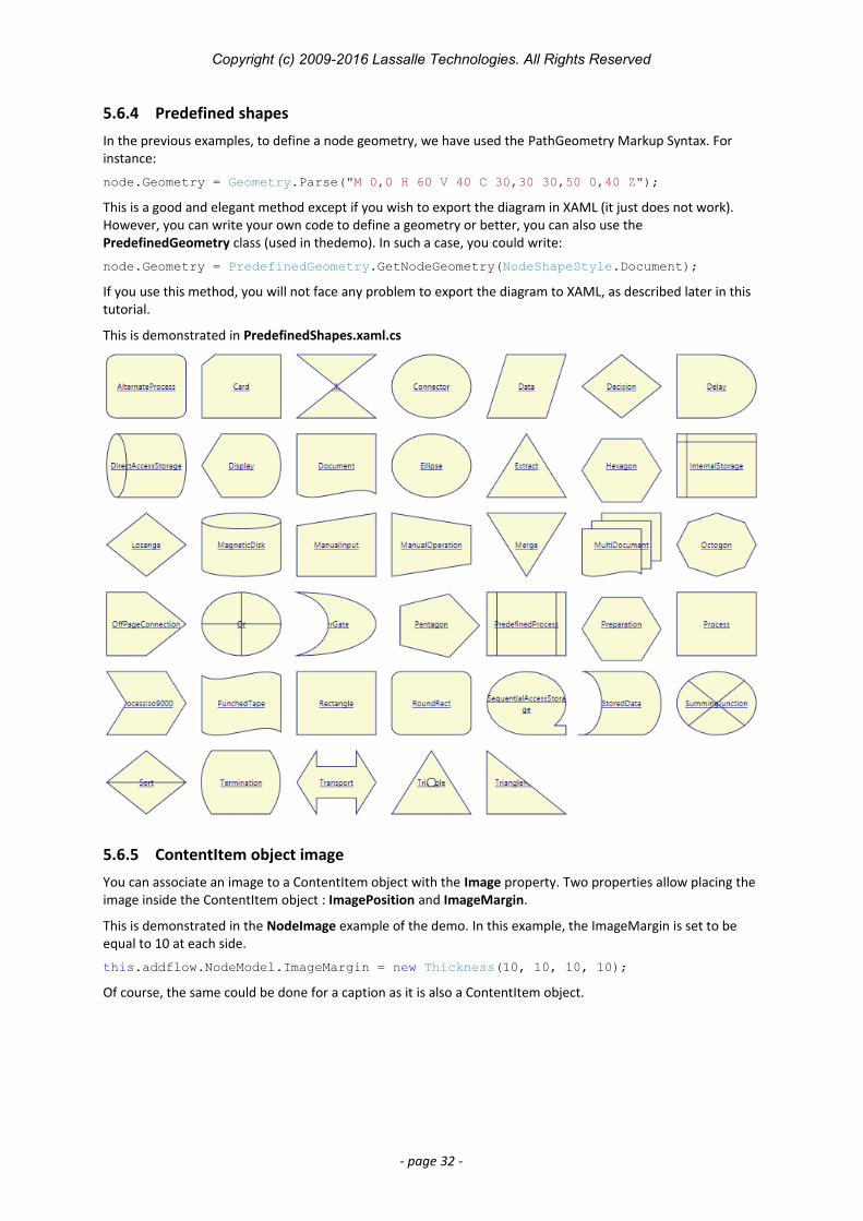
5.6.4 Predefined shapes
In the previous examples, to define a node geometry, we have used the PathGeometry Markup Syntax. For instance:
node.Geometry = Geometry.Parse("M 0,0 H 60 V 40 C 30,30 30,50 0,40 Z");
This is a good and elegant method except if you wish to export the diagram in XAML (it just does not work). However, you can write your own code to define a geometry or better, you can also use the PredefinedGeometry class (used in thedemo). In such a case, you could write:
node.Geometry = PredefinedGeometry.GetNodeGeometry(NodeShapeStyle.Document);
If you use this method, you will not face any problem to export the diagram to XAML, as described later in this tutorial.
This is demonstrated in PredefinedShapes.xaml.cs
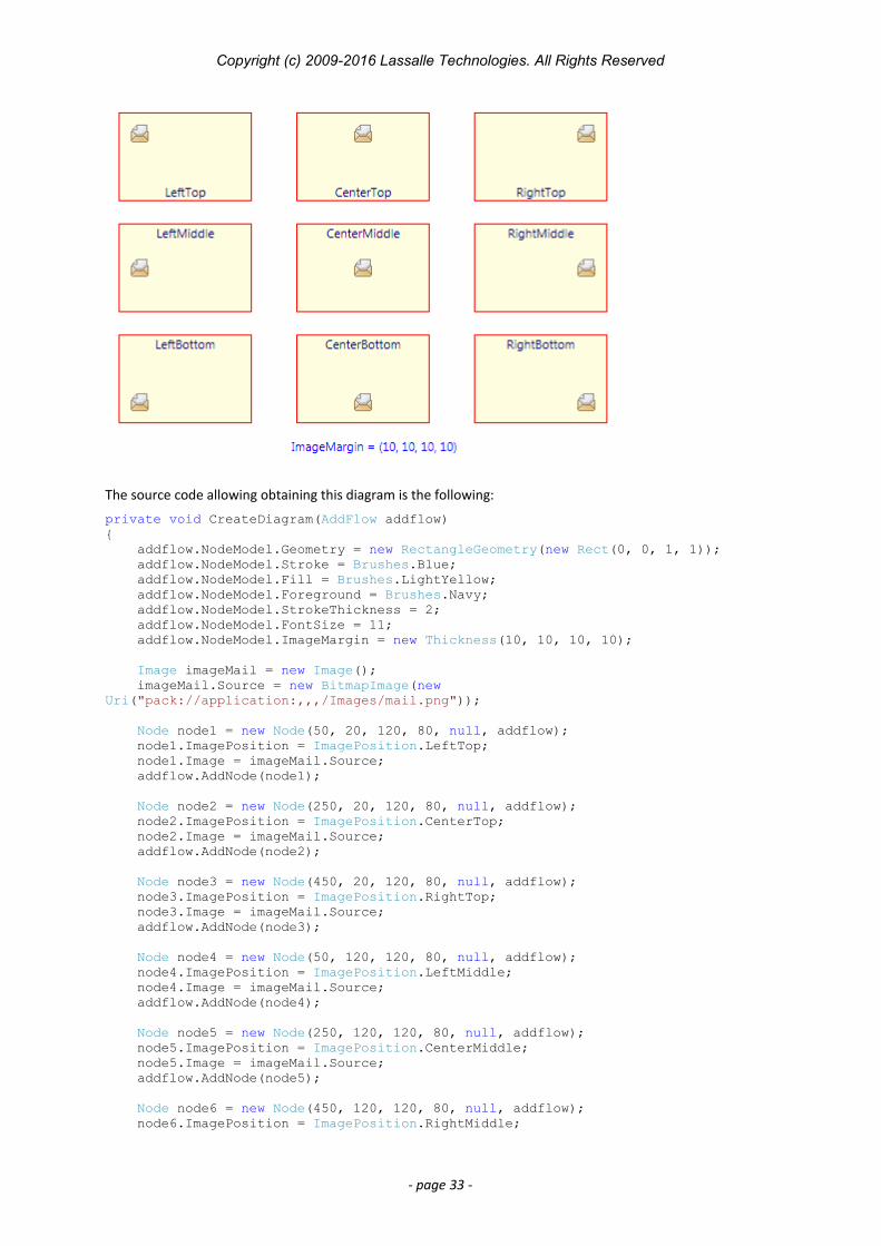
5.6.5 ContentItem object image
You can associate an image to a ContentItem object with the Image property. Two properties allow placing the image inside the ContentItem object : ImagePosition and ImageMargin.
This is demonstrated in the NodeImage example of the demo. In this example, the ImageMargin is set to be equal to 10 at each side.
this.addflow.NodeModel.ImageMargin = new Thickness(10, 10, 10, 10);
Of course, the same could be done for a caption as it is also a ContentItem object.
- page 32 -
Copyright (c) 2009-2016 Lassalle Technologies. All Rights Reserved
The source code allowing obtaining this diagram is the following:
private void CreateDiagram(AddFlow addflow){ addflow.NodeModel.Geometry = new RectangleGeometry(new Rect(0, 0, 1, 1)); addflow.NodeModel.Stroke = Brushes.Blue; addflow.NodeModel.Fill = Brushes.LightYellow; addflow.NodeModel.Foreground = Brushes.Navy; addflow.NodeModel.StrokeThickness = 2; addflow.NodeModel.FontSize = 11; addflow.NodeModel.ImageMargin = new Thickness(10, 10, 10, 10);
Image imageMail = new Image(); imageMail.Source = new BitmapImage(new Uri("pack://application:,,,/Images/mail.png"));
Node node1 = new Node(50, 20, 120, 80, null, addflow); node1.ImagePosition = ImagePosition.LeftTop; node1.Image = imageMail.Source; addflow.AddNode(node1);
Node node2 = new Node(250, 20, 120, 80, null, addflow); node2.ImagePosition = ImagePosition.CenterTop; node2.Image = imageMail.Source; addflow.AddNode(node2);
Node node3 = new Node(450, 20, 120, 80, null, addflow); node3.ImagePosition = ImagePosition.RightTop; node3.Image = imageMail.Source; addflow.AddNode(node3);
Node node4 = new Node(50, 120, 120, 80, null, addflow); node4.ImagePosition = ImagePosition.LeftMiddle; node4.Image = imageMail.Source; addflow.AddNode(node4);
Node node5 = new Node(250, 120, 120, 80, null, addflow); node5.ImagePosition = ImagePosition.CenterMiddle; node5.Image = imageMail.Source; addflow.AddNode(node5);
Node node6 = new Node(450, 120, 120, 80, null, addflow); node6.ImagePosition = ImagePosition.RightMiddle;
- page 33 -
Copyright (c) 2009-2016 Lassalle Technologies. All Rights Reserved
node6.Image = imageMail.Source; addflow.AddNode(node6);
Node node7 = new Node(50, 220, 120, 80, null, addflow); node7.ImagePosition = ImagePosition.LeftBottom; node7.Image = imageMail.Source; addflow.AddNode(node7);
Node node8 = new Node(250, 220, 120, 80, null, addflow); node8.ImagePosition = ImagePosition.CenterBottom; node8.Image = imageMail.Source; addflow.AddNode(node8);
Node node9 = new Node(450, 220, 120, 80, null, addflow); node9.ImagePosition = ImagePosition.RightBottom; node9.Image = imageMail.Source; addflow.AddNode(node9);}
Notice also the IsImageSizeFitContentArea property which determines whether the image of the contentItem object is adjusted to its size.
5.7 More informations about node pins
The way a link is connected to a node is managed by this node. Each node has 3 properties for this purpose: InConnectionMode, OutConnectionMode and PinsLayout.
The type of the InConnectionMode and OutConnectionMode properties is ConnectionMode. It is an enumeration that defines how the link is connected to the node.
Member Comment
Center Default. The link is directed towards the center of the node.
Anywhere The link last (or first) point can be placed anywhere.
Pin A pin a must be use to connect a link to the node.
When the mouse is over a node, pins are displayed on that node. Only nodes may have pins. By default, the node has only one pin placed at the center of the node. However, you are not limited to this 'central pin' and you can customize the set of pins.
Using the PinsLayout property, you may attach a set of pins to a node. The PinsLayout property is an array of points whose coordinates is between 0 and 100. For instance, the following line of code create a set of 4 pins for nodes:
addflow.NodeModel.PinsLayout = new PointCollection { new Point(0, 50), new Point(50, 0), new Point(100, 50), new Point(50, 100) };
This is demonstrated in the NodePins example of the demo.
private void CreateDiagram(AddFlow addflow){ addflow.NodeModel.Fill = Brushes.LightYellow; addflow.NodeModel.PinsLayout = new PointCollection { new Point(0, 50), new Point(50, 0), new Point(100, 50), new Point(50, 100) }; addflow.NodeModel.OutConnectionMode = ConnectionMode.Pin; addflow.NodeModel.InConnectionMode = ConnectionMode.Pin;
addflow.LinkModel.LineStyle = LineStyle.Orthogonal; addflow.LinkModel.Stroke = Brushes.Navy; addflow.LinkModel.ArrowGeometryDst = Geometry.Parse("M3,4L0,0 12,4 0,8z");
// Create 3 nodes. The first two nodes have 4 pins as it is // defined by default for every node. // However the third node has only 3 pins.
- page 34 -
Copyright (c) 2009-2016 Lassalle Technologies. All Rights Reserved
Node node1 = new Node(100, 30, 80, 80, "I have 4 pins", addflow); Node node2 = new Node(400, 250, 80, 80, "I have 4 pins", addflow); Node node3 = new Node(400, 30, 80, 80, "I have 3 pins", addflow); node3.PinsLayout = new PointCollection { new Point(0, 50), new Point(100, 50), new Point(50, 100) }; addflow.AddNode(node1); addflow.AddNode(node2); addflow.AddNode(node3);
// Create one link this.AddLink(addflow, node1, node2, 2, 0);}
Link AddLink(AddFlow addflow, Node org, Node dst, int pinOrgIndex, int pinDstIndex){ Link link = new Link(org, dst, pinOrgIndex, pinDstIndex, "", addflow); addflow.AddLink(link); return link;}
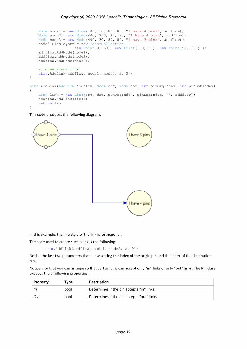
This code produces the following diagram:
In this example, the line style of the link is 'orthogonal'.
The code used to create such a link is the following:
this.AddLink(addflow, node1, node2, 2, 0);
Notice the last two parameters that allow setting the index of the origin pin and the index of the destination pin.
Notice also that you can arrange so that certain pins can accept only “in” links or only “out” links. The Pin class exposes the 2 following properties:
Property Type Description
In bool Determines if the pin accepts "in" links
Out bool Determines if the pin accepts "out" links
- page 35 -
Copyright (c) 2009-2016 Lassalle Technologies. All Rights Reserved
5.8 More informations about links
5.8.1 Link colors
Three properties allow setting colors for a Link object:
Stroke It is the brush used for the link line drawing Fill It is the brush used to fill the arrow head of the link. Foreground It is the brush of the link text.
5.8.2 Link text
You can associate a text to a node with the Text property. The TextPlacementMode property allows determining if the text is displayed at the middle point of the link line or at the middle point of the medium segment of the link.
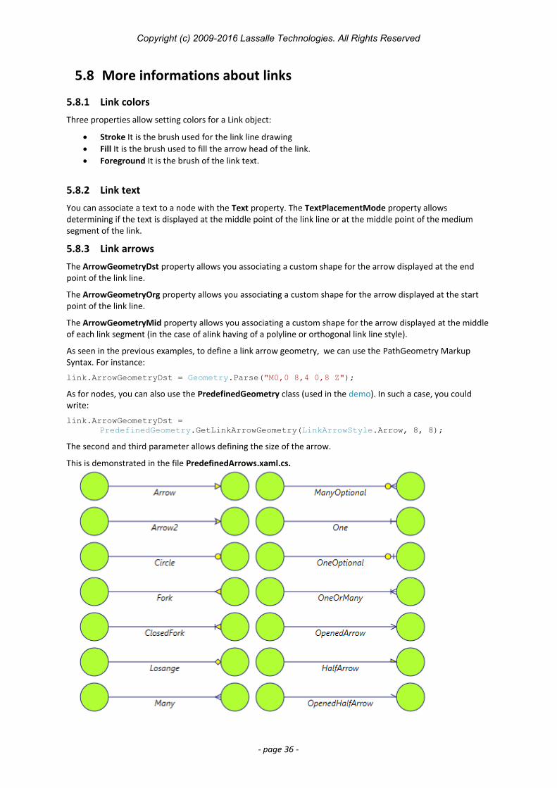
5.8.3 Link arrows
The ArrowGeometryDst property allows you associating a custom shape for the arrow displayed at the end point of the link line.
The ArrowGeometryOrg property allows you associating a custom shape for the arrow displayed at the start point of the link line.
The ArrowGeometryMid property allows you associating a custom shape for the arrow displayed at the middle of each link segment (in the case of alink having of a polyline or orthogonal link line style).
As seen in the previous examples, to define a link arrow geometry, we can use the PathGeometry Markup Syntax. For instance:
link.ArrowGeometryDst = Geometry.Parse("M0,0 8,4 0,8 Z");
As for nodes, you can also use the PredefinedGeometry class (used in the demo). In such a case, you could write:
link.ArrowGeometryDst =PredefinedGeometry.GetLinkArrowGeometry(LinkArrowStyle.Arrow, 8, 8);
The second and third parameter allows defining the size of the arrow.
This is demonstrated in the file PredefinedArrows.xaml.cs.
- page 36 -
Copyright (c) 2009-2016 Lassalle Technologies. All Rights Reserved
And of course, as for node shapes, you may define your own style of arrow head shape. The source code in the file PredefinedGeometry.cs may be a starting point for you.
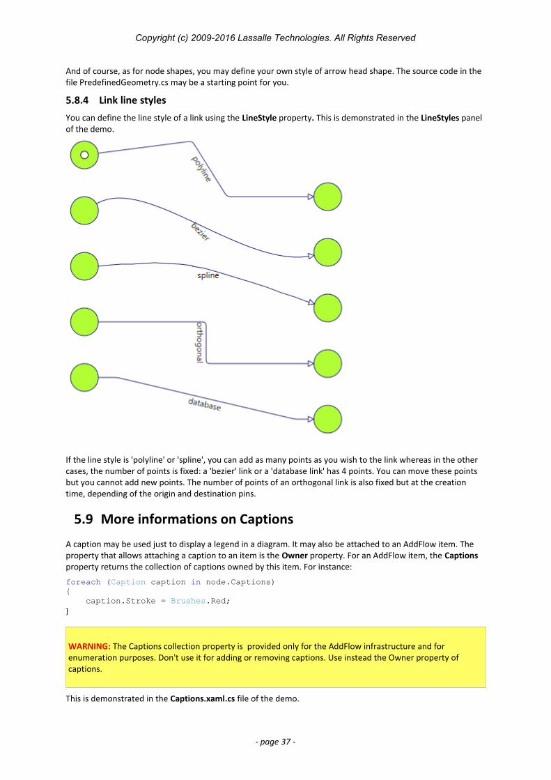
5.8.4 Link line styles
You can define the line style of a link using the LineStyle property. This is demonstrated in the LineStyles panel of the demo.
If the line style is 'polyline' or 'spline', you can add as many points as you wish to the link whereas in the other cases, the number of points is fixed: a 'bezier' link or a 'database link' has 4 points. You can move these points but you cannot add new points. The number of points of an orthogonal link is also fixed but at the creation time, depending of the origin and destination pins.
5.9 More informations on Captions
A caption may be used just to display a legend in a diagram. It may also be attached to an AddFlow item. The property that allows attaching a caption to an item is the Owner property. For an AddFlow item, the Captions property returns the collection of captions owned by this item. For instance:
foreach (Caption caption in node.Captions){ caption.Stroke = Brushes.Red;}
WARNING: The Captions collection property is provided only for the AddFlow infrastructure and for enumeration purposes. Don't use it for adding or removing captions. Use instead the Owner property of captions.
This is demonstrated in the Captions.xaml.cs file of the demo.
- page 37 -
Copyright (c) 2009-2016 Lassalle Technologies. All Rights Reserved
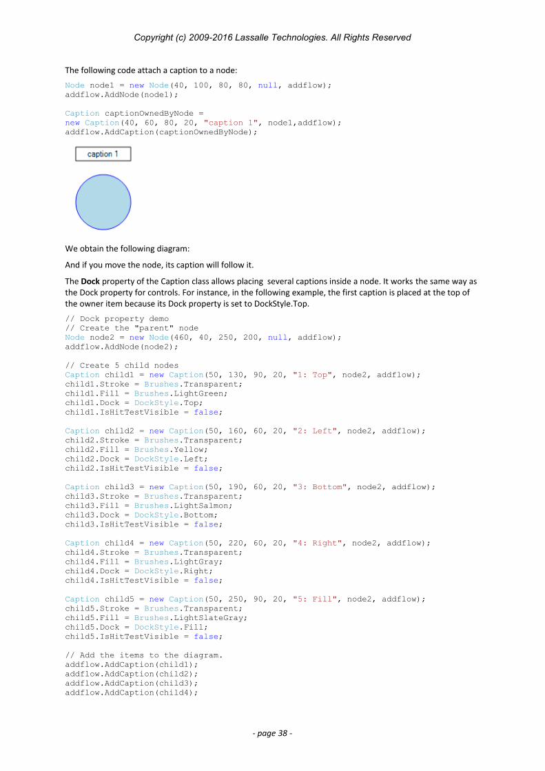
The following code attach a caption to a node:
Node node1 = new Node(40, 100, 80, 80, null, addflow);addflow.AddNode(node1);
Caption captionOwnedByNode = new Caption(40, 60, 80, 20, "caption 1", node1,addflow);addflow.AddCaption(captionOwnedByNode);
We obtain the following diagram:
And if you move the node, its caption will follow it.
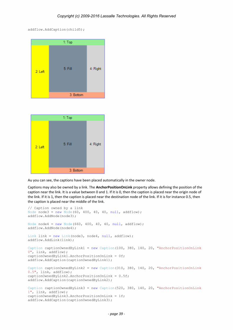
The Dock property of the Caption class allows placing several captions inside a node. It works the same way as the Dock property for controls. For instance, in the following example, the first caption is placed at the top of the owner item because its Dock property is set to DockStyle.Top.
// Dock property demo// Create the "parent" nodeNode node2 = new Node(460, 40, 250, 200, null, addflow);addflow.AddNode(node2);
// Create 5 child nodesCaption child1 = new Caption(50, 130, 90, 20, "1: Top", node2, addflow);child1.Stroke = Brushes.Transparent;child1.Fill = Brushes.LightGreen;child1.Dock = DockStyle.Top;child1.IsHitTestVisible = false;
Caption child2 = new Caption(50, 160, 60, 20, "2: Left", node2, addflow);child2.Stroke = Brushes.Transparent;child2.Fill = Brushes.Yellow;child2.Dock = DockStyle.Left;child2.IsHitTestVisible = false;
Caption child3 = new Caption(50, 190, 60, 20, "3: Bottom", node2, addflow);child3.Stroke = Brushes.Transparent;child3.Fill = Brushes.LightSalmon;child3.Dock = DockStyle.Bottom;child3.IsHitTestVisible = false;
Caption child4 = new Caption(50, 220, 60, 20, "4: Right", node2, addflow);child4.Stroke = Brushes.Transparent;child4.Fill = Brushes.LightGray;child4.Dock = DockStyle.Right;child4.IsHitTestVisible = false;
Caption child5 = new Caption(50, 250, 90, 20, "5: Fill", node2, addflow);child5.Stroke = Brushes.Transparent;child5.Fill = Brushes.LightSlateGray;child5.Dock = DockStyle.Fill;child5.IsHitTestVisible = false;
// Add the items to the diagram.addflow.AddCaption(child1);addflow.AddCaption(child2);addflow.AddCaption(child3);addflow.AddCaption(child4);
- page 38 -
Copyright (c) 2009-2016 Lassalle Technologies. All Rights Reserved
addflow.AddCaption(child5);
Au you can see, the captions have been placed automatically in the owner node.
Captions may also be owned by a link. The AnchorPositionOnLink property allows defining the position of the caption near the link. It is a value between 0 and 1. If it is 0, then the caption is placed near the origin node of the link. If it is 1, then the caption is placed near the destination node of the link. If it is for instance 0.5, then the caption is placed near the middle of the link.
// Caption owned by a linkNode node3 = new Node(60, 400, 40, 40, null, addflow);addflow.AddNode(node3);
Node node4 = new Node(660, 400, 40, 40, null, addflow);addflow.AddNode(node4);
Link link = new Link(node3, node4, null, addflow);addflow.AddLink(link);
Caption captionOwnedByLink1 = new Caption(100, 380, 140, 20, "AnchorPositionOnLink 0", link, addflow);captionOwnedByLink1.AnchorPositionOnLink = 0f;addflow.AddCaption(captionOwnedByLink1);
Caption captionOwnedByLink2 = new Caption(310, 380, 140, 20, "AnchorPositionOnLink 0.5", link, addflow);captionOwnedByLink2.AnchorPositionOnLink = 0.5f;addflow.AddCaption(captionOwnedByLink2);
Caption captionOwnedByLink3 = new Caption(520, 380, 140, 20, "AnchorPositionOnLink 1", link, addflow);captionOwnedByLink3.AnchorPositionOnLink = 1f;addflow.AddCaption(captionOwnedByLink3);
- page 39 -
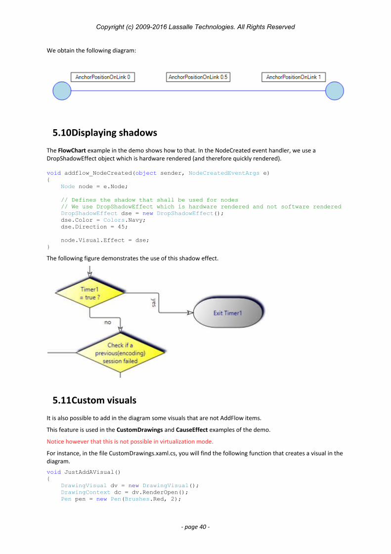
Copyright (c) 2009-2016 Lassalle Technologies. All Rights Reserved
We obtain the following diagram:
5.10Displaying shadows
The FlowChart example in the demo shows how to that. In the NodeCreated event handler, we use a DropShadowEffect object which is hardware rendered (and therefore quickly rendered).
void addflow_NodeCreated(object sender, NodeCreatedEventArgs e){ Node node = e.Node;
// Defines the shadow that shall be used for nodes // We use DropShadowEffect which is hardware rendered and not software rendered DropShadowEffect dse = new DropShadowEffect(); dse.Color = Colors.Navy; dse.Direction = 45;
node.Visual.Effect = dse;}
The following figure demonstrates the use of this shadow effect.
5.11Custom visuals
It is also possible to add in the diagram some visuals that are not AddFlow items.
This feature is used in the CustomDrawings and CauseEffect examples of the demo.
Notice however that this is not possible in virtualization mode.
For instance, in the file CustomDrawings.xaml.cs, you will find the following function that creates a visual in thediagram.
void JustAddAVisual(){ DrawingVisual dv = new DrawingVisual(); DrawingContext dc = dv.RenderOpen(); Pen pen = new Pen(Brushes.Red, 2);
- page 40 -
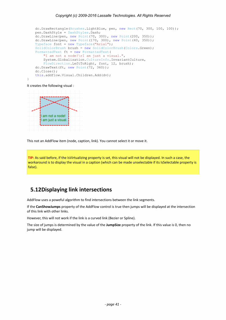
Copyright (c) 2009-2016 Lassalle Technologies. All Rights Reserved
dc.DrawRectangle(Brushes.LightBlue, pen, new Rect(70, 300, 100, 100)); pen.DashStyle = DashStyles.Dash; dc.DrawLine(pen, new Point(70, 300), new Point(200, 350)); dc.DrawLine(pen, new Point(170, 300), new Point(40, 350)); Typeface font = new Typeface("Arial"); SolidColorBrush brush = new SolidColorBrush(Colors.Green); FormattedText ft = new FormattedText( "I am not a node!\rI am just a visual.", System.Globalization.CultureInfo.InvariantCulture, FlowDirection.LeftToRight, font, 12, brush); dc.DrawText(ft, new Point(72, 360)); dc.Close(); this.addflow.Visual.Children.Add(dv);}
It creates the following visual :
This not an AddFlow item (node, caption, link). You cannot select it or move it.
TIP: As said before, if the IsVirtualizing property is set, this visual will not be displayed. In such a case, the workaround is to display the visual in a caption (which can be made unselectable if its IsSelectable property is false).
5.12Displaying link intersections
AddFlow uses a poweful algorithm to find intersections between the link segments.
If the CanShowJumps property of the AddFlow control is true then jumps will be displayed at the intersection of this link with other links.
However, this will not work if the link is a curved link (Bezier or Spline).
The size of jumps is determined by the value of the JumpSize property of the link. If this value is 0, then no jump will be displayed.
- page 41 -
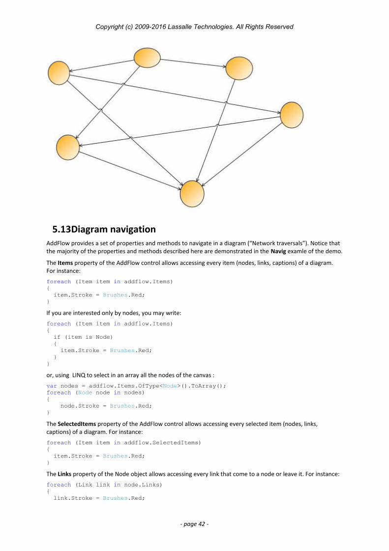
Copyright (c) 2009-2016 Lassalle Technologies. All Rights Reserved
5.13Diagram navigationAddFlow provides a set of properties and methods to navigate in a diagram (“Network traversals”). Notice that the majority of the properties and methods described here are demonstrated in the Navig examle of the demo.
The Items property of the AddFlow control allows accessing every item (nodes, links, captions) of a diagram. For instance:
foreach (Item item in addflow.Items){ item.Stroke = Brushes.Red;}
If you are interested only by nodes, you may write:
foreach (Item item in addflow.Items){ if (item is Node) { item.Stroke = Brushes.Red; }}
or, using LINQ to select in an array all the nodes of the canvas :
var nodes = addflow.Items.OfType<Node>().ToArray();foreach (Node node in nodes){ node.Stroke = Brushes.Red;}
The SelectedItems property of the AddFlow control allows accessing every selected item (nodes, links, captions) of a diagram. For instance:
foreach (Item item in addflow.SelectedItems){ item.Stroke = Brushes.Red;}
The Links property of the Node object allows accessing every link that come to a node or leave it. For instance:
foreach (Link link in node.Links){ link.Stroke = Brushes.Red;
- page 42 -
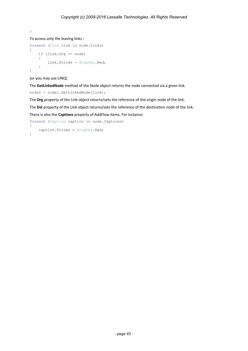
Copyright (c) 2009-2016 Lassalle Technologies. All Rights Reserved
}
To access only the leaving links :
foreach (Link link in node.Links){ if (link.Org == node) { link.Stroke = Brushes.Red; }}
(or you may use LINQ)
The GetLinkedNode method of the Node object returns the node connected via a given link.
node2 = node1.GetLinkedNode(link);
The Org property of the Link object returns/sets the reference of the origin node of the link.
The Dst property of the Link object returns/sets the reference of the destination node of the link.
There is also the Captions property of AddFlow items. For instance:
foreach (Caption caption in node.Captions){ caption.Stroke = Brushes.Red;}
- page 43 -
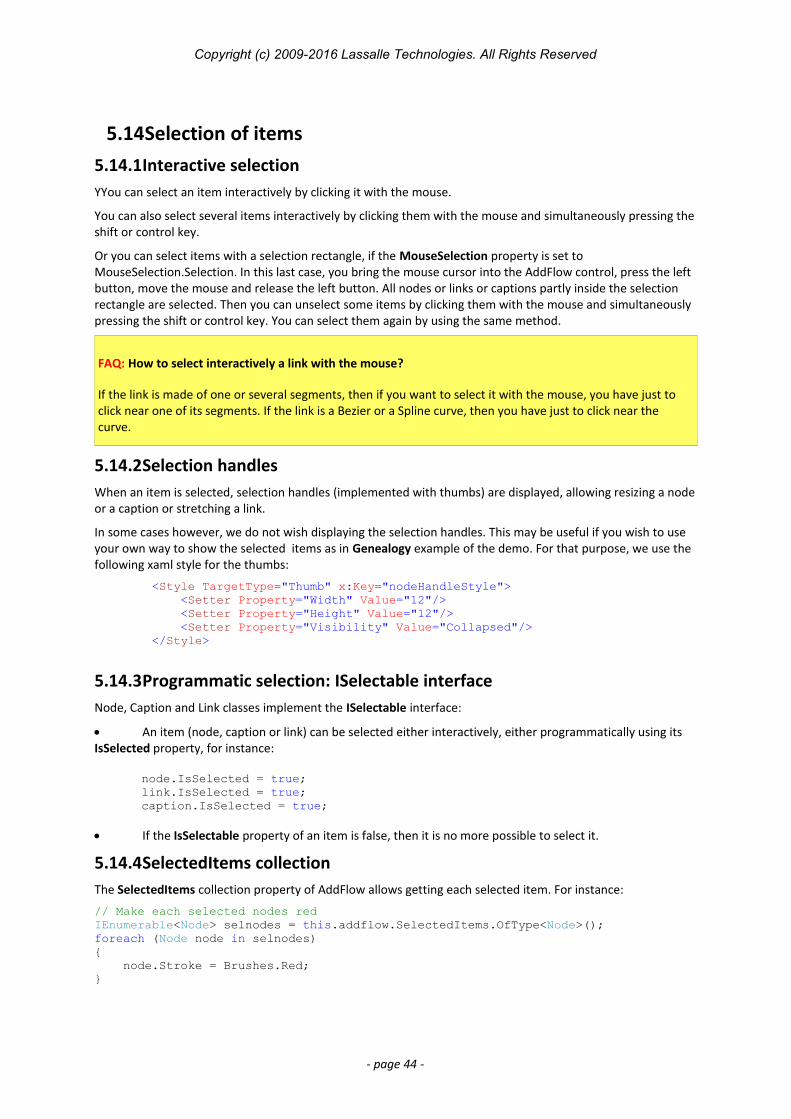
Copyright (c) 2009-2016 Lassalle Technologies. All Rights Reserved
5.14Selection of items5.14.1Interactive selectionYYou can select an item interactively by clicking it with the mouse.
You can also select several items interactively by clicking them with the mouse and simultaneously pressing theshift or control key.
Or you can select items with a selection rectangle, if the MouseSelection property is set to MouseSelection.Selection. In this last case, you bring the mouse cursor into the AddFlow control, press the left button, move the mouse and release the left button. All nodes or links or captions partly inside the selection rectangle are selected. Then you can unselect some items by clicking them with the mouse and simultaneously pressing the shift or control key. You can select them again by using the same method.
FAQ: How to select interactively a link with the mouse?
If the link is made of one or several segments, then if you want to select it with the mouse, you have just to click near one of its segments. If the link is a Bezier or a Spline curve, then you have just to click near the curve.
5.14.2Selection handlesWhen an item is selected, selection handles (implemented with thumbs) are displayed, allowing resizing a nodeor a caption or stretching a link.
In some cases however, we do not wish displaying the selection handles. This may be useful if you wish to use your own way to show the selected items as in Genealogy example of the demo. For that purpose, we use the following xaml style for the thumbs:
<Style TargetType="Thumb" x:Key="nodeHandleStyle"> <Setter Property="Width" Value="12"/> <Setter Property="Height" Value="12"/> <Setter Property="Visibility" Value="Collapsed"/> </Style>
5.14.3Programmatic selection: ISelectable interfaceNode, Caption and Link classes implement the ISelectable interface:
An item (node, caption or link) can be selected either interactively, either programmatically using its IsSelected property, for instance:
node.IsSelected = true;link.IsSelected = true;caption.IsSelected = true;
If the IsSelectable property of an item is false, then it is no more possible to select it.
5.14.4SelectedItems collectionThe SelectedItems collection property of AddFlow allows getting each selected item. For instance:
// Make each selected nodes redIEnumerable<Node> selnodes = this.addflow.SelectedItems.OfType<Node>();foreach (Node node in selnodes){ node.Stroke = Brushes.Red;}
- page 44 -
Copyright (c) 2009-2016 Lassalle Technologies. All Rights Reserved
WARNING: there is a difference with previous versions. In this version, there is not any notion of a “current” (or “active”) item and therefore there is not any property like SelectedNode, SelectedLink or SelectedItem. When several items (nodes or links) are selected, you cannot designate one that could be the current one.
5.14.5Selection event
The SelectionChanged event is fired each time the selection status of an item is changed. However, you can avoid that by setting the CanSendSelectionChangedEvent property to false.
5.14.6Hit TestingYou can also know what object is under the mouse with the HitItem property that returns the reference of the item under the mouse. If several objects are under the mouse, the returned object is the one that is at the top of the Z-order list. AddFlow provide some methods allowing changing this order (BringToFront, SendToBack, ...)
If the IsHitTestVisible property of an item is false, then this item cannot be hit tested.
Instead of using the HitItem property, you may use the GetItemAt method.
5.15Zooming
AddFlow provides also some properties and methods that control the general aspect of a diagram:
Extent Returns the size of the diagram.
Origin Returns the top left location of the diagram.
Zoom Returns/sets the zooming factor. It is a double value representing the zoom factor. Its default value is equal to 1. Notice that the zoom is isotropic ensuring a 1:1 aspect ratio.
ZoomRectangle A method allowing zooming a rectangular portion of the diagram
TIP: How to autofit the diagram; i.e. how to adjust the zoom to its maximum while still keeping all the shapes (nodes, links etc.) in view?
You can implement this feature using the ZoomRectangle method:
Point location = this.addflow.Origin;Size size = this.addflow.Extent;this.addflow.ZoomRectangle(new Rect(location.X, location.Y, size.Width, size.Height));
5.16Zordering
Yoy may change the z-order index of an item by using the AddFlow methods SendToBack, BringToFront, SendBackward, BringForward to send the selected items at the back of the zorder list or bring them at the front of the zorder list.
- page 45 -
Copyright (c) 2009-2016 Lassalle Technologies. All Rights Reserved
5.17SerializationXMLFlow allows serializing an AddFlow diagram. More precisely, this assembly provides a class named Serial that offers methods for saving/loading an AddFlow diagram in a file or copying/pasting a portion of it onto the clipboard.
This component is free and its C# source code is provided with AddFlow.
You may also develop your own method for serializing an AddFlow diagram. In such a case, the source code of XMLFlow may be a starting point for you.
XMLFlow is used in the Demo (in the MainWindow.xaml.cs file), in the 5 following static methods:
static void LoadFile(AddFlow addflow, string strFileName){ XElement root = XElement.Load(strFileName); Serial.LoadXML(addflow, XElement.Load(strFileName));}
static void SaveFile(AddFlow addflow, string strFileName){ XElement xElement = Serial.SaveXML(addflow); xElement.Save(strFileName);}
static void Cut(AddFlow addflow){ Serial.Cut(addflow);}
static void Copy(AddFlow addflow){ Serial.Copy(addflow);}
static void Paste(AddFlow addflow){ Serial.Paste(addflow, false);}
5.18Printing a diagramAddFlow itself does not offer any printing feature. See the DiagramPaginator.cs file of the demo to see how you can print a diagram.
Notice that currently, print previewing is not still implemented.
5.19Exporting a diagram in XAML
AddFlow itself does not offer any exporting feature. However, the file ExportXaml.xaml.cs of the demo shows how to do that.
If you click on the “Export to XAML” button, all the drawings of the AddFlow control are saved in a XAML file, then this XAML file is loaded and displayed as the content in a Label control placed at the right of the AddFlow control.
This is accomplished by the following routine:
void ExportToXaml(){ // Add all the Addflow drawings to the Children collection of // a DrawingGroup object DrawingGroup drawingGroup = new DrawingGroup(); foreach (DrawingVisual dv in this.addflow.Visual.Children) { DrawingGroup dg = dv.Drawing.Clone();
- page 46 -
Copyright (c) 2009-2016 Lassalle Technologies. All Rights Reserved
dg.Append(); foreach (DrawingVisual child in dv.Children) { dg.Children.Add(child.Drawing); } drawingGroup.Children.Add(dg); }
// Wrap the DrawingGroup in an image Image image = new Image(); image.Stretch = Stretch.None; DrawingImage drawingImage = new DrawingImage(); drawingImage.Drawing = drawingGroup; image.Source = drawingImage;
// Save the image in a XAML file System.Xml.XmlTextWriter writer =
new System.Xml.XmlTextWriter(@"ExportedDiagram.xaml", null); System.Windows.Markup.XamlWriter.Save(image, writer); writer.Close();
// Load the obtained XAML file and display it in a Label control // at the right of the AddFlow control System.IO.FileStream fs =
new System.IO.FileStream(@"ExportedDiagram.xaml", System.IO.FileMode.Open); Image img = System.Windows.Markup.XamlReader.Load(fs) as Image; this.XAMLView.Content = img;}
WARNING: It will not work if you use the PathGeometry Markup Syntax to define the node geometries or the link arrow geometries. You have to define them programmatically.
For instance, if you use the following code to create a node:
node.Geometry = Geometry.Parse("M 0,20 L 30,0 L 60,20 L 30,40 Z");
Instead you have to use the following:
node.Geometry = PredefinedGeometry.GetNodeGeometry(NodeShapeStyle.Decision);
And you cannot define a link arrow geometry using for instance:
link2.ArrowGeometryDst = Geometry.Parse("M3,4 L0,0 12,4 0,8 Z");
Instead you have to use the following:
link2.ArrowGeometryDst = PredefinedGeometry.GetLinkArrowGeometry(LinkArrowStyle.Arrow2, 8, 8);
This suppose that, as in the demo, you have added a reference to Lassalle.WPF.Geometries. But you are not forced to use this class. You may also define your geometry yourself. For instance, the code to create a losange geometry would be the following:
node.Geometry = MakeDecisionGeometry(new Rect(0, 0, 64, 64));
The MakeDecisionGeometry method could be the following:
static Geometry MakeDecisionGeometry(Rect rc){ PathGeometry pathGeometry = new PathGeometry(); PathFigure pathFigure = new PathFigure();
PolyLineSegment polylineSegment = new PolyLineSegment(); polylineSegment.Points.Add(new Point(rc.Left, rc.Top + rc.Height / 2)); polylineSegment.Points.Add(new Point(rc.Left + rc.Width / 2, rc.Top)); polylineSegment.Points.Add(new Point(rc.Right, rc.Top + rc.Height / 2)); polylineSegment.Points.Add(new Point(rc.Left + rc.Width / 2, rc.Bottom));
- page 47 -
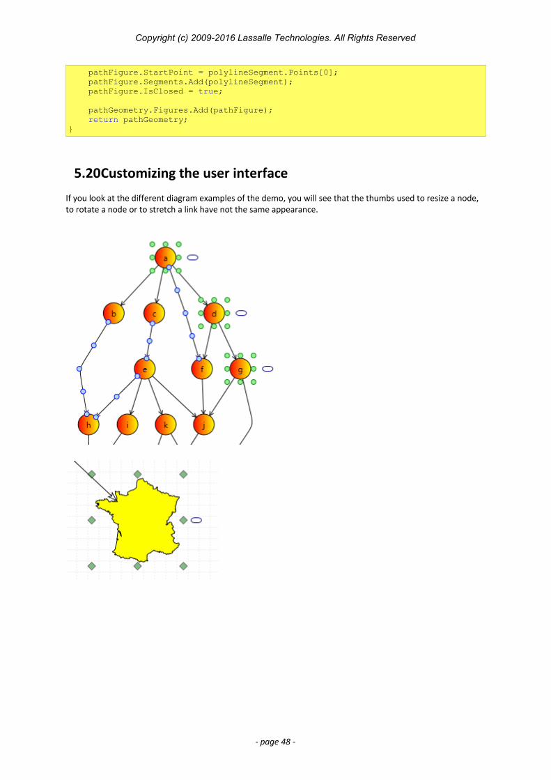
Copyright (c) 2009-2016 Lassalle Technologies. All Rights Reserved
pathFigure.StartPoint = polylineSegment.Points[0]; pathFigure.Segments.Add(polylineSegment); pathFigure.IsClosed = true;
pathGeometry.Figures.Add(pathFigure); return pathGeometry;}
5.20Customizing the user interface
If you look at the different diagram examples of the demo, you will see that the thumbs used to resize a node, to rotate a node or to stretch a link have not the same appearance.
- page 48 -
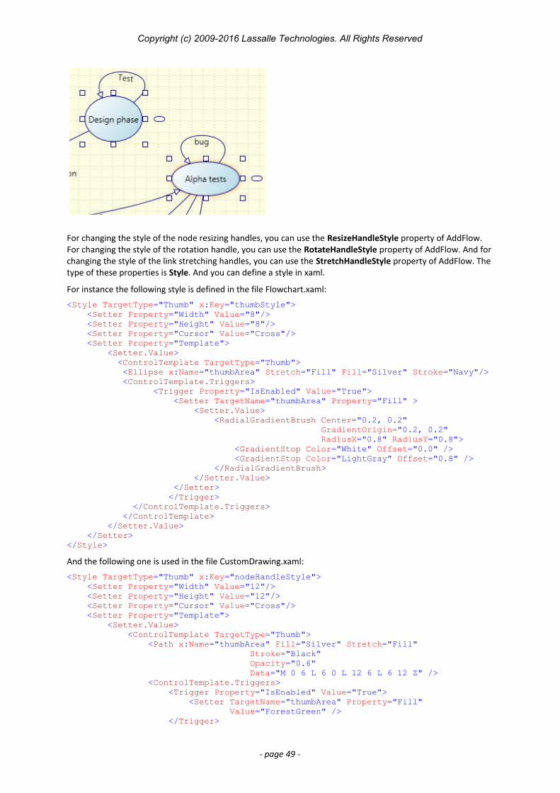
Copyright (c) 2009-2016 Lassalle Technologies. All Rights Reserved
For changing the style of the node resizing handles, you can use the ResizeHandleStyle property of AddFlow. For changing the style of the rotation handle, you can use the RotateHandleStyle property of AddFlow. And for changing the style of the link stretching handles, you can use the StretchHandleStyle property of AddFlow. The type of these properties is Style. And you can define a style in xaml.
For instance the following style is defined in the file Flowchart.xaml:
<Style TargetType="Thumb" x:Key="thumbStyle"> <Setter Property="Width" Value="8"/> <Setter Property="Height" Value="8"/> <Setter Property="Cursor" Value="Cross"/> <Setter Property="Template"> <Setter.Value> <ControlTemplate TargetType="Thumb"> <Ellipse x:Name="thumbArea" Stretch="Fill" Fill="Silver" Stroke="Navy"/> <ControlTemplate.Triggers> <Trigger Property="IsEnabled" Value="True"> <Setter TargetName="thumbArea" Property="Fill" > <Setter.Value> <RadialGradientBrush Center="0.2, 0.2" GradientOrigin="0.2, 0.2" RadiusX="0.8" RadiusY="0.8"> <GradientStop Color="White" Offset="0.0" /> <GradientStop Color="LightGray" Offset="0.8" /> </RadialGradientBrush> </Setter.Value> </Setter> </Trigger> </ControlTemplate.Triggers> </ControlTemplate> </Setter.Value> </Setter></Style>
And the following one is used in the file CustomDrawing.xaml:
<Style TargetType="Thumb" x:Key="nodeHandleStyle"> <Setter Property="Width" Value="12"/> <Setter Property="Height" Value="12"/> <Setter Property="Cursor" Value="Cross"/> <Setter Property="Template"> <Setter.Value> <ControlTemplate TargetType="Thumb"> <Path x:Name="thumbArea" Fill="Silver" Stretch="Fill" Stroke="Black" Opacity="0.6" Data="M 0 6 L 6 0 L 12 6 L 6 12 Z" /> <ControlTemplate.Triggers> <Trigger Property="IsEnabled" Value="True"> <Setter TargetName="thumbArea" Property="Fill" Value="ForestGreen" /> </Trigger>
- page 49 -

Copyright (c) 2009-2016 Lassalle Technologies. All Rights Reserved
</ControlTemplate.Triggers> </ControlTemplate> </Setter.Value> </Setter></Style>
Then, to use these styles, you have just to assign them to the ResizeHandleStyle, RotateHandleStyle and StretchHandleStyle properties of the AddFlow control. For instance:
<af:AddFlow Name="addflow" GridDraw="True" GridSnap="True" GridColor="DarkGray" BorderThickness="6"ResizeHandleStyle="{StaticResource nodeHandleStyle}" StretchHandleStyle="{StaticResource linkHandleStyle}"/>
- page 50 -
Copyright (c) 2009-2016 Lassalle Technologies. All Rights Reserved
6 Avanced topics6.1 Undo/Redo
6.1.1 General features
AddFlow has a property named TaskManager of type TaskManager that provides a powerful multilevel Undo/Redo feature. The history length is limited only by available memory. However, you can limit it yourself with the UndoLimit property of the TaskManager class. You can also enable/disable the undo/redo with the CanUndoRedo property of AddFlow.
6.1.2 Updating the user interface
Some properties and methods allow you to properly update the user interface. The CanUndo and CanRedo methods will tell you if there is something to undo or redo and therefore will allow you to grey out the menu options. The RedoCode and UndoCode properties return a code that describes the action waiting to be redone or undone. This will allow your application to give descriptions of the actions on the undo and redo history.
6.1.3 Grouping basic actions
Every basic action has a code. However, the BeginAction and EndAction methods allow you to define a group of actions and to assign a code to this group. This is useful if for instance, in your application, the user can open a dialog box allowing changing several properties of a node (for instance, its text, its shape and its filling color). You will certainly wish to allow the user to undo these 3 basic actions in one time.
Notice that you can also stop recording actions with the SkipUndo method and also clear the Undo/Redo buffer with the Clear method.
Another interesting method is the AddToLastAction method. For instance, it allows grouping some actions withthe last recorded action or group of actions.
Notice that you have to call the EndAction to terminate the group of actions.
6.1.4 What can be undone and redone?The rule is the following: every interactive action that changes a diagram can be undone or redone. This includes actions like moving or resizing nodes or stretching links or changing a text.
However, making a selection does not change the document so you will not be able to undo a selection. Changing properties of the AddFlow control (zoom, grid, default filling color, etc) does not change the document too. Therefore, it will not be possible to undo these actions. And finally, file, print and export operations are clearly not undoable.
WARNING: there is a difference with some previous versions (ActiveX version for instance). In the WPF version, only the interactive actions can be undone and redone. In the previous versions, all actions changing a node or a link could be undone or redone. For instance, you could undo a change of the XMoveable property of a node. In the WPF version, you will have to write a custom task to be able to undo a change of the IsXMoveable property. This is explained in the following paragraph.
6.1.5 Undo/Redo customization
The undo/redo can be customized. For that, you have to create a custom Task class by deriving the Task class and then you can insert it in the undo list with the SubmitTask method. The file CustomUndo example of the demo shows how to do that: if you double-click on a node, a dialog box allows you changing the text and the tooltip of that node. And then, you can undo this action.
For doing that, we have created a class deriving from the Task class. This new class implements the task consisting in changing both the node text and node tooltip.
- page 51 -
Copyright (c) 2009-2016 Lassalle Technologies. All Rights Reserved
internal class NodePropertiesTask : Task{ private string oldText; private string oldTooltip; private Node node;
private NodePropertiesTask() { }
internal NodePropertiesTask(Node node, string oldText, string oldTooltip) { this.Code = (Lassalle.WPF.Flow.Action)1002; this.node = node; this.oldText = oldText; this.oldTooltip = oldTooltip; }
public override void Redo() { this.Undo(); }
public override void Undo() { string oldText = this.node.Text; this.node.Text = this.oldText; this.oldText = oldText;
string oldTooltip = this.node.Tooltip as string; this.node.Tooltip = this.oldTooltip; this.oldTooltip = oldTooltip; }}
The code of the mouse double click event handler is the following:
private void addflow_MouseLeftButtonDown(object sender, System.Windows.Input.MouseButtonEventArgs e){ if (e.ClickCount == 2) { if (this.addflow.SelectedItems != null && this.addflow.SelectedItems.Count > 0) { if (this.addflow.SelectedItems[0] is Node) { Node node = this.addflow.SelectedItems[0] as Node; NodePropDlg nodePropDlg = new NodePropDlg(node); Point pt = this.addflow.PointToScreen(node.Location); nodePropDlg.Left = pt.X; nodePropDlg.Top = pt.Y; if (nodePropDlg.ShowDialog() == true) { this.addflow.TaskManager.SubmitTask( new NodePropertiesTask(node, node.Text, node.Tooltip as string)); node.Text = nodePropDlg.NodeText; node.Tooltip = nodePropDlg.NodeToolTip; } } } }}
As you can see, after having closed the dialog box and if it returns true (in such a case, the action is accepted) and before the node receives new values for its Text and Tooltip properties, you can find the following code line:
this.addflow.TaskManager.SubmitTask(new NodePropertiesTask(node, node.Text, node.Tooltip as string));
- page 52 -
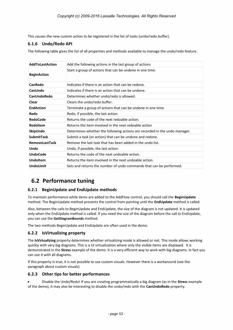
Copyright (c) 2009-2016 Lassalle Technologies. All Rights Reserved
This causes the new custom action to be registered in the list of tasks (undo/redo buffer).
6.1.6 Undo/Redo API
The following table gives the list of all properties and methods available to manage the undo/redo feature.
AddToLastAction Add the following actions in the last group of actions
BeginActionStart a group of actions that can be undone in one time.
CanRedo Indicates if there is an action that can be redone.CanUndo Indicates if there is an action that can be undone.CanUndoRedo Determines whether undo/redo is allowed.Clear Clears the undo/redo buffer.EndAction Terminate a group of actions that can be undone in one time.Redo Redo, if possible, the last action.RedoCode Returns the code of the next redoable action.RedoItem Returns the item involved in the next redoable actionSkipUndo Determines whether the following actions are recorded in the undo manager.SubmitTask Submit a task (or action) that can be undone and redone.RemoveLastTask Remove the last task that has been added in the undo list.Undo Undo, if possible, the last action.UndoCode Returns the code of the next undoable action.UndoItem Returns the item involved in the next undoable action.UndoLimit Sets and returns the number of undo commands that can be performed.
6.2 Performance tuning6.2.1 BeginUpdate and EndUpdate methods
To maintain performance while items are added to the AddFlow control, you should call the BeginUpdate method. The BeginUpdate method prevents the control from painting until the EndUpdate method is called.
Also, between the calls to BeginUpdate and EndUpdate, the size of the diagram is not updated. It is updated only when the EndUpdate method is called. If you need the size of the diagram before the call to EndUpdate, you can use the GetDiagramBounds method.
The two methods BeginUpdate and EndUpdate are often used in the demo.
6.2.2 IsVirtualizing property
The IsVirtualizing property determines whether virtualizing mode is allowed or not. This mode allows working quickly with very big diagrams. This is a UI virtualization where only the visible items are displayed. It is demonstrated in the Stress example of the demo. It is a very efficient way to work with big diagrams. In fact youcan use it with all diagrams.
If this property is true, it is not possible to use custom visuals. However there is a workaround (see the paragraph about custom visuals).
6.2.3 Other tips for better performances
Disable the Undo/Redo! If you are creating programmatically a big diagram (as in the Stress example of the demo), it may also be interesting to disable the undo/redo with the CanUndoRedo property.
- page 53 -
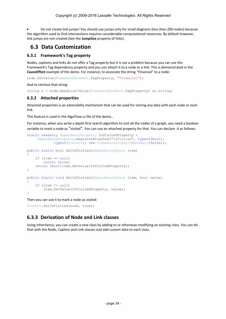
Copyright (c) 2009-2016 Lassalle Technologies. All Rights Reserved
Do not create link jumps! You should use jumps only for small diagrams (less than 200 nodes) because the algorithm used to find intersections requires considerable computational resources. By default however, link jumps are not created (See the JumpSize property of links).
6.3 Data Customization6.3.1 Framework's Tag property
Nodes, captions and links do not offer a Tag property but it is not a problem because you can use the Framework's Tag dependency property and you can attach it to a node or a link. This is demonstrated in the CauseEffect example of the demo. For instance, to associate the string "Financial" to a node:
node.SetValue(FrameworkElement.TagProperty, "Financial");
And to retrieve that string:
string s = node.ReadLocalValue(FrameworkElement.TagProperty) as string;
6.3.2 Attached properties
Attached properties is an extensibilty mechanism that can be used for storing any data with each node or each link.
This feature is used in the AlgoFlow.cs file of the demo..
For instance, when you write a depth first search algorithm to visit all the nodes of a graph, you need a booleanvariable to mark a node as "visited". You can use an attached property for that. You can declare it as follows:
static readonly DependencyProperty IsVisitedProperty = DependencyProperty.RegisterAttached("IsVisited", typeof(bool),
typeof(Connect), new FrameworkPropertyMetadata(false));
public static bool GetIsVisited(DependencyObject item){ if (item == null) return false; return (bool)item.GetValue(IsVisitedProperty);}
public static void SetIsVisited(DependencyObject item, bool value){ if (item != null) item.SetValue(IsVisitedProperty, value);}
Then you can use it to mark a node as visited:
Connect.SetIsVisited(node, true);
6.3.3 Derivation of Node and Link classesUsing inheritance, you can create a new class by adding to or otherwise modifying an existing class. You can do that with the Node, Caption and Link classes and add custom data to each class.
- page 54 -
Copyright (c) 2009-2016 Lassalle Technologies. All Rights Reserved
7 Automatic Graph Layout
WARNING: this feature is available without any restriction (nag screen) only if you have purchased a Professional license of AddFlow for WPF.
The primary purpose of an automatic graph layout feature is to offer a way to display graphs or flow charts in a reasonable manner, following some aesthetic rules.
AddFlow does not provide directly any automatic graph layout feature. However, we propose LayoutFlow which provides a set of 5 graph layout algorithms:
o Hierarchic layouto Orthogonal layouto Symmetric layouto Series Parallel layouto Tree layout
Each of these graph layout algorithms performs a layout on a graph. Performing a layout automatically positions its nodes (also called vertices) and links (also called edges).
Typically, you can first create your nodes and links inside AddFlow, using the AddFlow API, giving each node a random or a (0,0) position. Then you call the layout method of the graph layout control of your choice. This method will position the nodes and the links in a reasonable manner in the AddFlow control, following some aesthetic rules that depend on the chosen control (hierarchical, symmetric, orthogonal...).
Remarks
Currently, LayoutFlow is an AddFlow extension and you cannot use it without AddFlow. If you just want to perform a layout on a graph without displaying them in an AddFlow control (for instance because you have already a way to display the diagram), then you can use both a hidden AddFlow control and LayoutFlow to do that. In such a case, AddFlow is just used to store the logical structure of the graph and to retrieve via its API, the resulting positions of its nodes and links.
The demo shows how to use each graph layout component. Reflexive links are not taken into account by layout algorithms. Reflexive links are just translated to
follow their origin (and also destination) node.
TIP: How to manage so that the layout algorithm applies only to a subset of the graph?
LayoutFlow provides an attached property: IsLogical. Only the nodes and links whose IsLogical property is trueare involved in each layout. This will allow you to make the layout algorithm to ignore some nodes or links. By default, the IsLogical property is true.
7.1 Hierarchic layout
7.1.1 Purpose
This algorithm performs a hierarchical layout on a graph. The hierarchical layout arranges vertices in horizontal layers. The order of the nodes on the layers is chosen so that the number of crossings is kept as small as possible.
- page 55 -
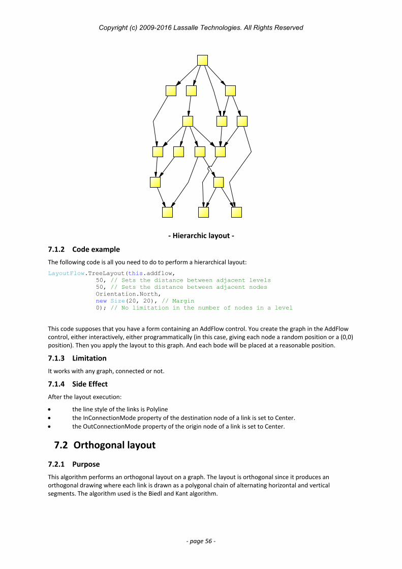
Copyright (c) 2009-2016 Lassalle Technologies. All Rights Reserved
- Hierarchic layout -
7.1.2 Code example
The following code is all you need to do to perform a hierarchical layout:
LayoutFlow.TreeLayout(this.addflow, 50, // Sets the distance between adjacent levels50, // Sets the distance between adjacent nodesOrientation.North, new Size(20, 20), // Margin0); // No limitation in the number of nodes in a level
This code supposes that you have a form containing an AddFlow control. You create the graph in the AddFlow control, either interactively, either programmatically (in this case, giving each node a random position or a (0,0)position). Then you apply the layout to this graph. And each bode will be placed at a reasonable position.
7.1.3 Limitation
It works with any graph, connected or not.
7.1.4 Side Effect
After the layout execution:
the line style of the links is Polyline the InConnectionMode property of the destination node of a link is set to Center. the OutConnectionMode property of the origin node of a link is set to Center.
7.2 Orthogonal layout
7.2.1 Purpose
This algorithm performs an orthogonal layout on a graph. The layout is orthogonal since it produces an orthogonal drawing where each link is drawn as a polygonal chain of alternating horizontal and vertical segments. The algorithm used is the Biedl and Kant algorithm.
- page 56 -
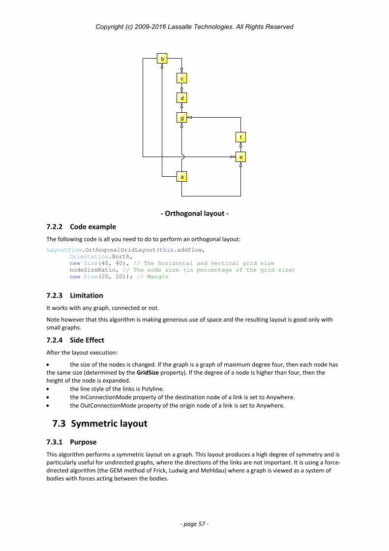
Copyright (c) 2009-2016 Lassalle Technologies. All Rights Reserved
a
b
c
d
e
f
g
- Orthogonal layout -
7.2.2 Code example
The following code is all you need to do to perform an orthogonal layout:
LayoutFlow.OrthogonalGridLayout(this.addflow, Orientation.North, new Size(40, 40), // The horizontal and vertical grid sizenodeSizeRatio, // The node size (in percentage of the grid size)new Size(20, 20)); // Margin
7.2.3 Limitation
It works with any graph, connected or not.
Note however that this algorithm is making generous use of space and the resulting layout is good only with small graphs.
7.2.4 Side Effect
After the layout execution:
the size of the nodes is changed. If the graph is a graph of maximum degree four, then each node has the same size (determined by the GridSize property). If the degree of a node is higher than four, then the height of the node is expanded. the line style of the links is Polyline. the InConnectionMode property of the destination node of a link is set to Anywhere. the OutConnectionMode property of the origin node of a link is set to Anywhere.
7.3 Symmetric layout
7.3.1 Purpose
This algorithm performs a symmetric layout on a graph. This layout produces a high degree of symmetry and is particularly useful for undirected graphs, where the directions of the links are not important. It is using a force-directed algorithm (the GEM method of Frick, Ludwig and Mehldau) where a graph is viewed as a system of bodies with forces acting between the bodies.
- page 57 -
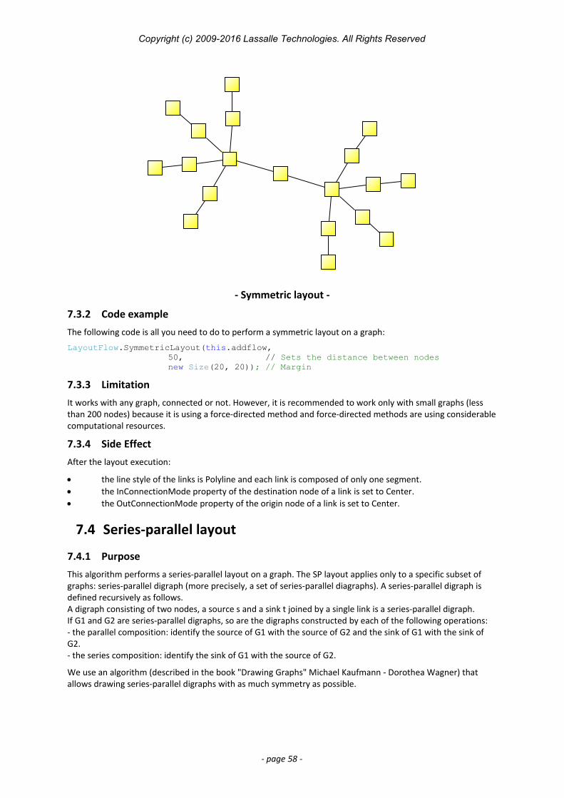
Copyright (c) 2009-2016 Lassalle Technologies. All Rights Reserved
- Symmetric layout -
7.3.2 Code example
The following code is all you need to do to perform a symmetric layout on a graph:
LayoutFlow.SymmetricLayout(this.addflow, 50, // Sets the distance between nodesnew Size(20, 20)); // Margin
7.3.3 Limitation
It works with any graph, connected or not. However, it is recommended to work only with small graphs (less than 200 nodes) because it is using a force-directed method and force-directed methods are using considerablecomputational resources.
7.3.4 Side Effect
After the layout execution:
the line style of the links is Polyline and each link is composed of only one segment. the InConnectionMode property of the destination node of a link is set to Center. the OutConnectionMode property of the origin node of a link is set to Center.
7.4 Series-parallel layout
7.4.1 Purpose
This algorithm performs a series-parallel layout on a graph. The SP layout applies only to a specific subset of graphs: series-parallel digraph (more precisely, a set of series-parallel diagraphs). A series-parallel digraph is defined recursively as follows.A digraph consisting of two nodes, a source s and a sink t joined by a single link is a series-parallel digraph.If G1 and G2 are series-parallel digraphs, so are the digraphs constructed by each of the following operations:- the parallel composition: identify the source of G1 with the source of G2 and the sink of G1 with the sink of G2.- the series composition: identify the sink of G1 with the source of G2.
We use an algorithm (described in the book "Drawing Graphs" Michael Kaufmann - Dorothea Wagner) that allows drawing series-parallel digraphs with as much symmetry as possible.
- page 58 -
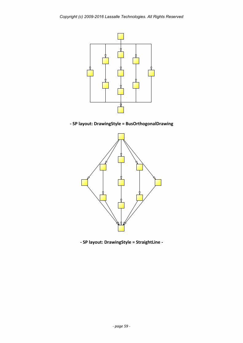
Copyright (c) 2009-2016 Lassalle Technologies. All Rights Reserved
- SP layout: DrawingStyle = BusOrthogonalDrawing
- SP layout: DrawingStyle = StraightLine -
- page 59 -
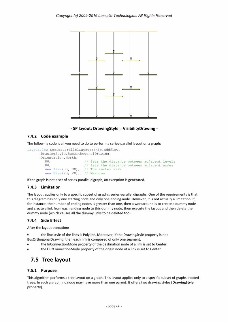
Copyright (c) 2009-2016 Lassalle Technologies. All Rights Reserved
- SP layout: DrawingStyle = VisibilityDrawing -
7.4.2 Code example
The following code is all you need to do to perform a series-parallel layout on a graph:
LayoutFlow.SeriesParallelLayout(this.addflow, DrawingStyle.BusOrthogonalDrawing, Orientation.North, 80, // Sets the distance between adjacent levels 80, // Sets the distance between adjacent nodes new Size(30, 30), // The vertex size new Size(20, 20)); // Margins
If the graph is not a set of series-parallel digraph, an exception is generated.
7.4.3 Limitation
The layout applies only to a specific subset of graphs: series-parallel digraphs. One of the requirements is that this diagram has only one starting node and only one ending node. However, it is not actually a limitation. If, for instance, the number of ending nodes is greater than one, then a workaround is to create a dummy node and create a link from each ending node to this dummy node, then execute the layout and then delete the dummy node (which causes all the dummy links to be deleted too).
7.4.4 Side Effect
After the layout execution:
the line style of the links is Polyline. Moreover, if the DrawingStyle property is not BusOrthogonalDrawing, then each link is composed of only one segment. the InConnectionMode property of the destination node of a link is set to Center. the OutConnectionMode property of the origin node of a link is set to Center.
7.5 Tree layout
7.5.1 Purpose
This algorithm performs a tree layout on a graph. This layout applies only to a specific subset of graphs: rooted trees. In such a graph, no node may have more than one parent. It offers two drawing styles (DrawingStyle property).
- page 60 -
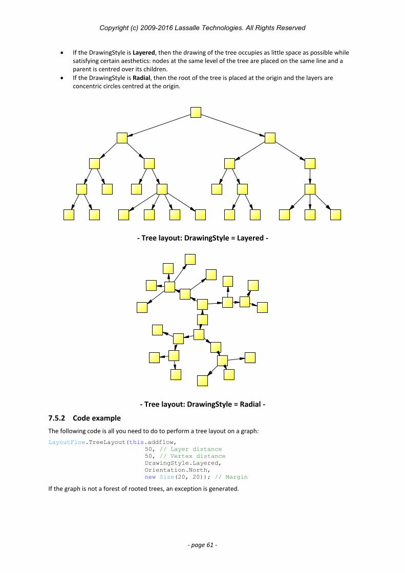
Copyright (c) 2009-2016 Lassalle Technologies. All Rights Reserved
If the DrawingStyle is Layered, then the drawing of the tree occupies as little space as possible while satisfying certain aesthetics: nodes at the same level of the tree are placed on the same line and a parent is centred over its children.
If the DrawingStyle is Radial, then the root of the tree is placed at the origin and the layers are concentric circles centred at the origin.
- Tree layout: DrawingStyle = Layered -
- Tree layout: DrawingStyle = Radial -
7.5.2 Code example
The following code is all you need to do to perform a tree layout on a graph:
LayoutFlow.TreeLayout(this.addflow, 50, // Layer distance50, // Vertex distanceDrawingStyle.Layered, Orientation.North, new Size(20, 20)); // Margin
If the graph is not a forest of rooted trees, an exception is generated.
- page 61 -

Copyright (c) 2009-2016 Lassalle Technologies. All Rights Reserved
7.5.3 Limitation
The layout applies only to a specific subset of graphs: rooted trees. More precisely, the layout applies to forests(sets of rooted trees).
7.5.4 Side Effect
After the layout execution:
the line style of the links is Polyline the InConnectionMode property of the destination node of a link is set to Center. the OutConnectionMode property of the origin node of a link is set to Center.
- page 62 -