Embed Size (px)
Citation preview
ARC ADJUSTMENT INSTRUCTIONS G85B and G885 Rotors
① Arc adjustments can be made with the rotor
in operation or while the rotor is in the static off
condition. These instructions cover initial arc
setup and adjustment while the rotor is in the
static off condition and with the riser installed
in the rotor.
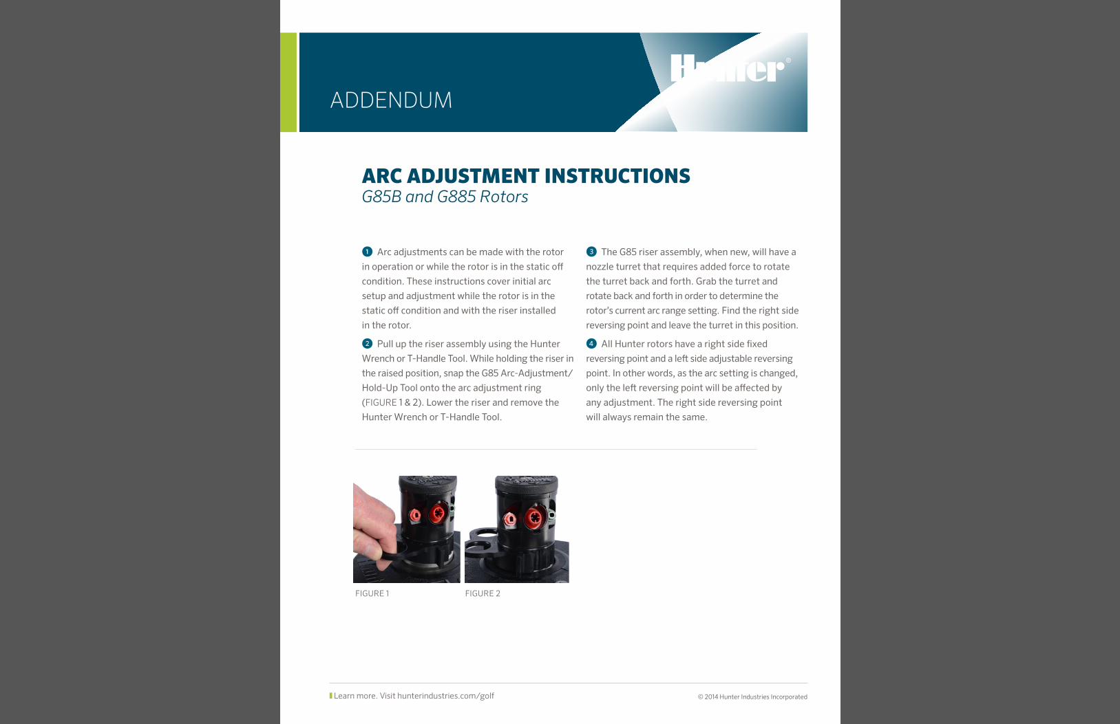
② Pull up the riser assembly using the Hunter
Wrench or T-Handle Tool. While holding the riser in
the raised position, snap the G85 Arc-Adjustment/
Hold-Up Tool onto the arc adjustment ring
(FIGURE 1 & 2). Lower the riser and remove the
Hunter Wrench or T-Handle Tool.
③ The G85 riser assembly, when new, will have a
nozzle turret that requires added force to rotate
the turret back and forth. Grab the turret and
rotate back and forth in order to determine the
rotor’s current arc range setting. Find the right side
reversing point and leave the turret in this position.
④ All Hunter rotors have a right side fixed
reversing point and a left side adjustable reversing
point. In other words, as the arc setting is changed,
only the left reversing point will be affected by
any adjustment. The right side reversing point
will always remain the same.
Learn more. Visit hunterindustries.com/golf © 2014 Hunter Industries Incorporated
ADDENDUM
FIGURE 1 FIGURE 2
ARC ADJUSTMENT
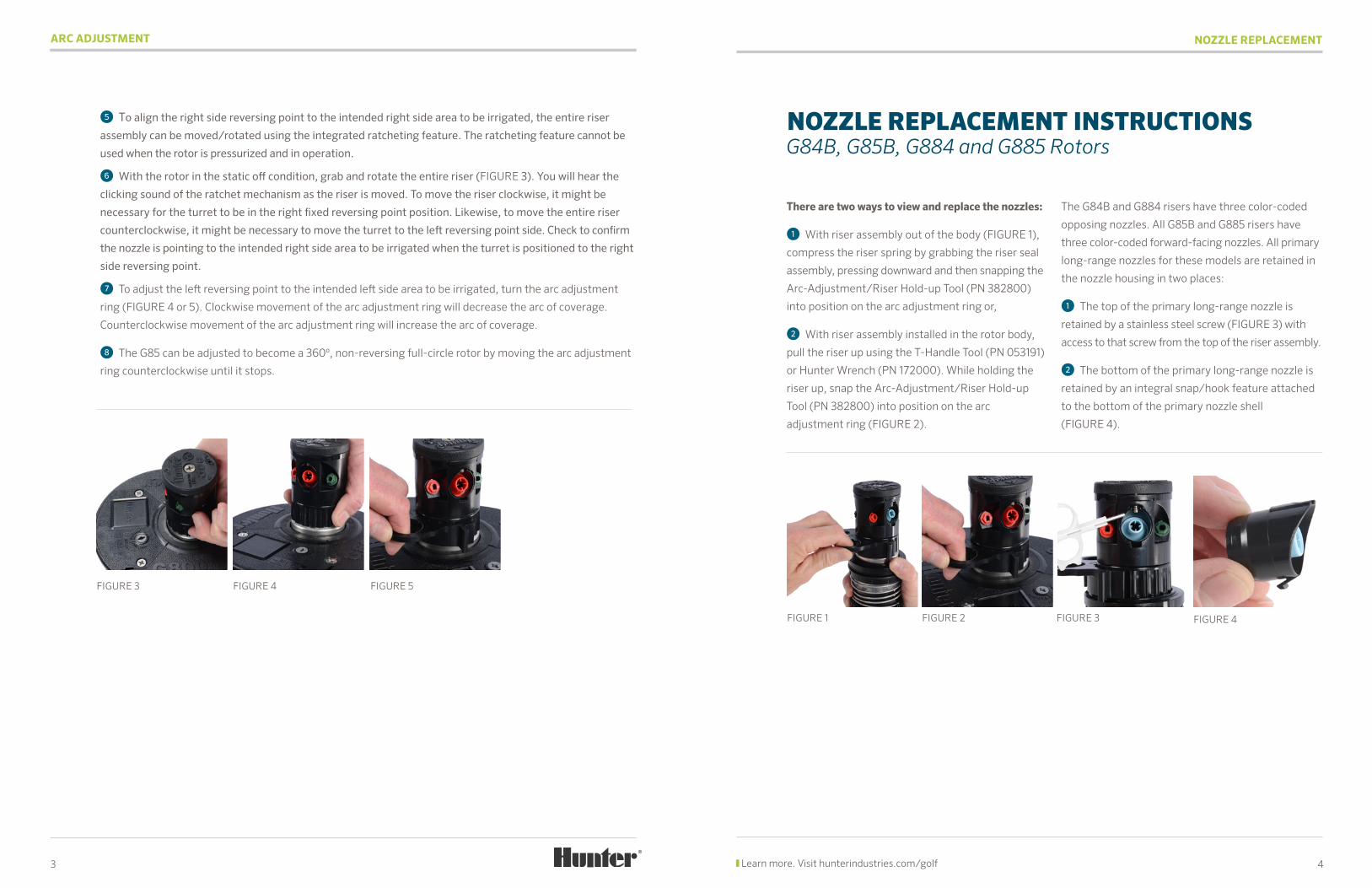
⑤ To align the right side reversing point to the intended right side area to be irrigated, the entire riser
assembly can be moved/rotated using the integrated ratcheting feature. The ratcheting feature cannot be
used when the rotor is pressurized and in operation.
⑥ With the rotor in the static off condition, grab and rotate the entire riser (FIGURE 3). You will hear the
clicking sound of the ratchet mechanism as the riser is moved. To move the riser clockwise, it might be
necessary for the turret to be in the right fixed reversing point position. Likewise, to move the entire riser
counterclockwise, it might be necessary to move the turret to the left reversing point side. Check to confirm
the nozzle is pointing to the intended right side area to be irrigated when the turret is positioned to the right
side reversing point.
⑦ To adjust the left reversing point to the intended left side area to be irrigated, turn the arc adjustment
ring (FIGURE 4 or 5). Clockwise movement of the arc adjustment ring will decrease the arc of coverage.
Counterclockwise movement of the arc adjustment ring will increase the arc of coverage.
⑧ The G85 can be adjusted to become a 360º, non-reversing full-circle rotor by moving the arc adjustment
ring counterclockwise until it stops.
There are two ways to view and replace the nozzles:
① With riser assembly out of the body (FIGURE 1),
compress the riser spring by grabbing the riser seal
assembly, pressing downward and then snapping the
Arc-Adjustment/Riser Hold-up Tool (PN 382800)
into position on the arc adjustment ring or,
② With riser assembly installed in the rotor body,
pull the riser up using the T-Handle Tool (PN 053191)
or Hunter Wrench (PN 172000). While holding the
riser up, snap the Arc-Adjustment/Riser Hold-up
Tool (PN 382800) into position on the arc
adjustment ring (FIGURE 2).
The G84B and G884 risers have three color-coded
opposing nozzles. All G85B and G885 risers have
three color-coded forward-facing nozzles. All primary
long-range nozzles for these models are retained in
the nozzle housing in two places:
① The top of the primary long-range nozzle is
retained by a stainless steel screw (FIGURE 3) with
access to that screw from the top of the riser assembly.
② The bottom of the primary long-range nozzle is
retained by an integral snap/hook feature attached
to the bottom of the primary nozzle shell
(FIGURE 4).
4
NOZZLE REPLACEMENT
Learn more. Visit hunterindustries.com/golf3
FIGURE 3 FIGURE 4 FIGURE 5
NOZZLE REPLACEMENT INSTRUCTIONS G84B, G85B, G884 and G885 Rotors
FIGURE 1 FIGURE 4FIGURE 2 FIGURE 3
NOZZLE REPLACEMENT
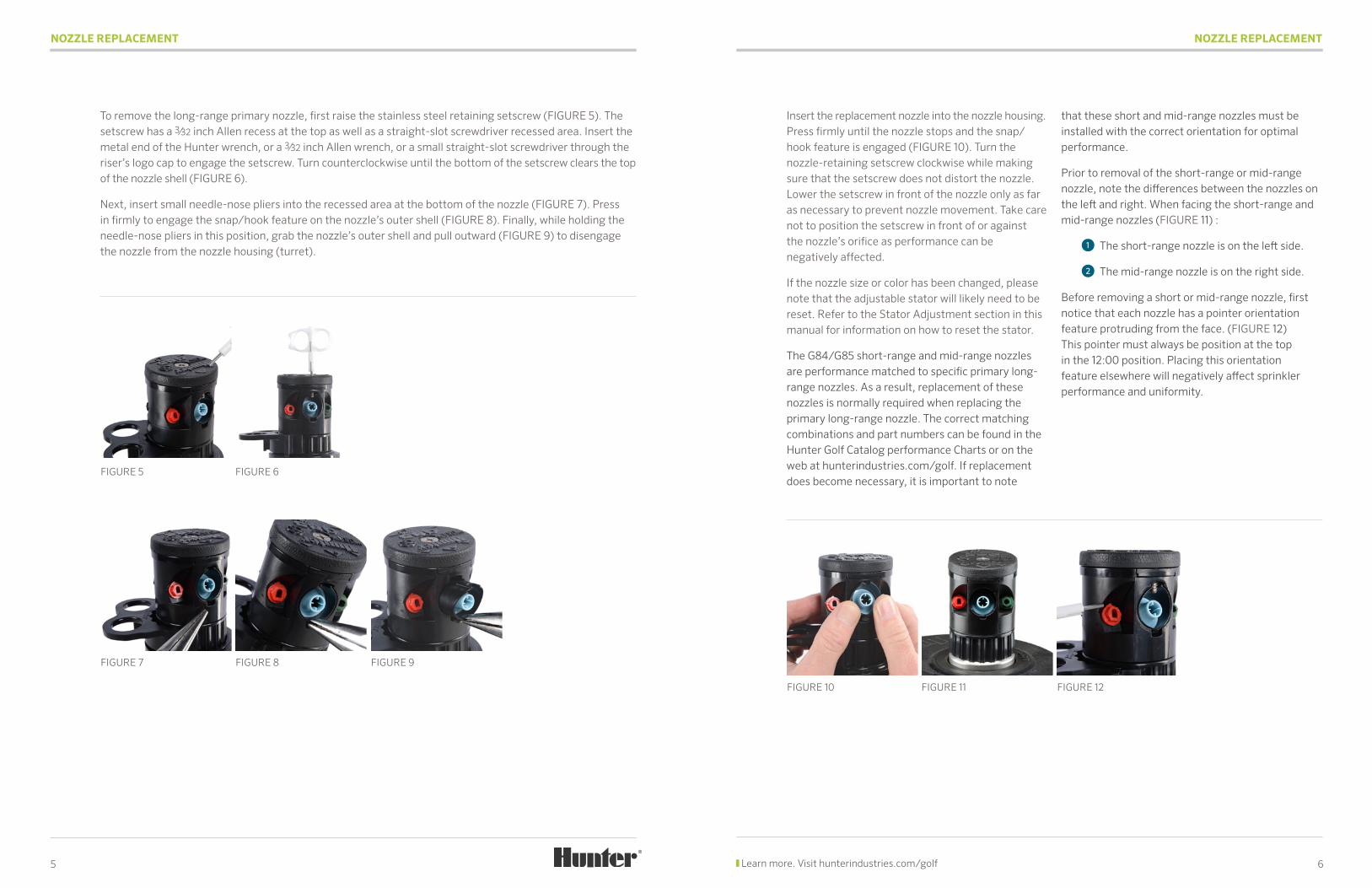
To remove the long-range primary nozzle, first raise the stainless steel retaining setscrew (FIGURE 5). The setscrew has a 3⁄32 inch Allen recess at the top as well as a straight-slot screwdriver recessed area. Insert the metal end of the Hunter wrench, or a 3⁄32 inch Allen wrench, or a small straight-slot screwdriver through the riser’s logo cap to engage the setscrew. Turn counterclockwise until the bottom of the setscrew clears the top of the nozzle shell (FIGURE 6).
Next, insert small needle-nose pliers into the recessed area at the bottom of the nozzle (FIGURE 7). Press in firmly to engage the snap/hook feature on the nozzle’s outer shell (FIGURE 8). Finally, while holding the needle-nose pliers in this position, grab the nozzle’s outer shell and pull outward (FIGURE 9) to disengage the nozzle from the nozzle housing (turret).
5
FIGURE 5
FIGURE 7
FIGURE 6
FIGURE 8 FIGURE 9
NOZZLE REPLACEMENT
Insert the replacement nozzle into the nozzle housing. Press firmly until the nozzle stops and the snap/hook feature is engaged (FIGURE 10). Turn the nozzle-retaining setscrew clockwise while making sure that the setscrew does not distort the nozzle. Lower the setscrew in front of the nozzle only as far as necessary to prevent nozzle movement. Take care not to position the setscrew in front of or against the nozzle’s orifice as performance can be negatively affected.
If the nozzle size or color has been changed, please note that the adjustable stator will likely need to be reset. Refer to the Stator Adjustment section in this manual for information on how to reset the stator.
The G84/G85 short-range and mid-range nozzles are performance matched to specific primary long-range nozzles. As a result, replacement of these nozzles is normally required when replacing the primary long-range nozzle. The correct matching combinations and part numbers can be found in the Hunter Golf Catalog performance Charts or on the web at hunterindustries.com/golf. If replacement does become necessary, it is important to note
that these short and mid-range nozzles must be installed with the correct orientation for optimal performance.
Prior to removal of the short-range or mid-range nozzle, note the differences between the nozzles on the left and right. When facing the short-range and mid-range nozzles (FIGURE 11) :
① The short-range nozzle is on the left side.
② The mid-range nozzle is on the right side.
Before removing a short or mid-range nozzle, first notice that each nozzle has a pointer orientation feature protruding from the face. (FIGURE 12) This pointer must always be position at the top in the 12:00 position. Placing this orientation feature elsewhere will negatively affect sprinkler performance and uniformity.
FIGURE 10 FIGURE 11 FIGURE 12
6 Learn more. Visit hunterindustries.com/golf
NOZZLE REPLACEMENT
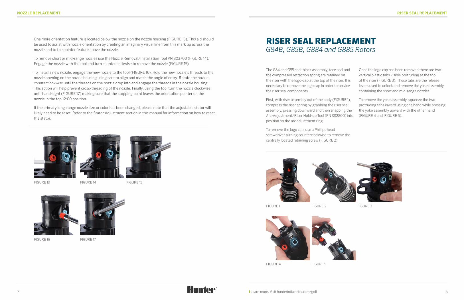
One more orientation feature is located below the nozzle on the nozzle housing (FIGURE 13). This aid should be used to assist with nozzle orientation by creating an imaginary visual line from this mark up across the nozzle and to the pointer feature above the nozzle.
To remove short or mid-range nozzles use the Nozzle Removal/Installation Tool PN 803700 (FIGURE 14). Engage the nozzle with the tool and turn counterclockwise to remove the nozzle (FIGURE 15).
To install a new nozzle, engage the new nozzle to the tool (FIGURE 16). Hold the new nozzle’s threads to the nozzle opening on the nozzle housing using care to align and match the angle of entry. Rotate the nozzle counterclockwise until the threads on the nozzle drop into and engage the threads in the nozzle housing. This action will help prevent cross-threading of the nozzle. Finally, using the tool turn the nozzle clockwise until hand-tight (FIGURE 17) making sure that the stopping point leaves the orientation pointer on the nozzle in the top 12:00 position.
If the primary long-range nozzle size or color has been changed, please note that the adjustable stator will likely need to be reset. Refer to the Stator Adjustment section in this manual for information on how to reset the stator.
7
FIGURE 16
FIGURE 13
FIGURE 17
FIGURE 14 FIGURE 15
RISER SEAL REPLACEMENT
The G84 and G85 seal-block assembly, face seal and the compressed retraction spring are retained on the riser with the logo-cap at the top of the riser. It is necessary to remove the logo cap in order to service the riser seal components.
First, with riser assembly out of the body (FIGURE 1), compress the riser spring by grabbing the riser seal assembly, pressing downward and then snapping the Arc-Adjustment/Riser Hold-up Tool (PN 382800) into position on the arc adjustment ring.
To remove the logo cap, use a Phillips head screwdriver turning counterclockwise to remove the centrally located retaining screw (FIGURE 2).
Once the logo cap has been removed there are two vertical plastic tabs visible protruding at the top of the riser (FIGURE 3). These tabs are the release levers used to unlock and remove the yoke assembly containing the short and mid-range nozzles.
To remove the yoke assembly, squeeze the two protruding tabs inward using one hand while pressing the yoke assembly upward with the other hand (FIGURE 4 and FIGURE 5).
FIGURE 1
FIGURE 4
FIGURE 2
FIGURE 5
FIGURE 3
RISER SEAL REPLACEMENT G84B, G85B, G884 and G885 Rotors
8 Learn more. Visit hunterindustries.com/golf
RISER SEAL REPLACEMENT
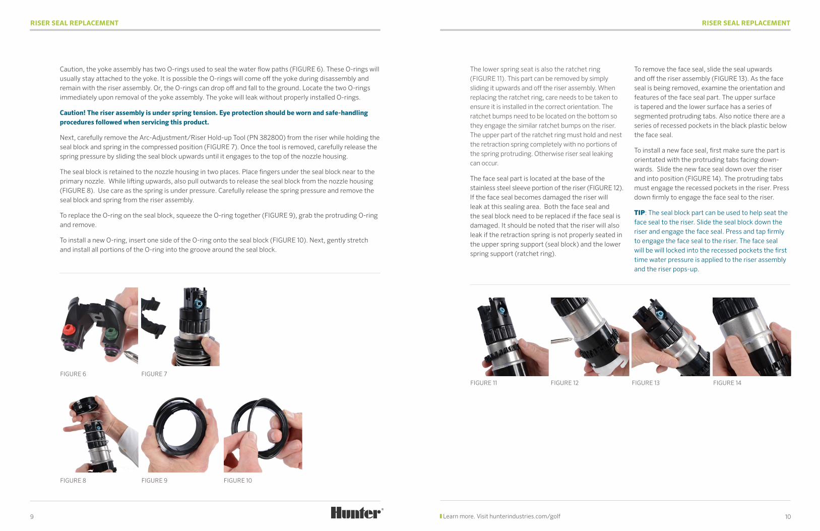
Caution, the yoke assembly has two O-rings used to seal the water flow paths (FIGURE 6). These O-rings will usually stay attached to the yoke. It is possible the O-rings will come off the yoke during disassembly and remain with the riser assembly. Or, the O-rings can drop off and fall to the ground. Locate the two O-rings immediately upon removal of the yoke assembly. The yoke will leak without properly installed O-rings.
Caution! The riser assembly is under spring tension. Eye protection should be worn and safe-handling procedures followed when servicing this product.
Next, carefully remove the Arc-Adjustment/Riser Hold-up Tool (PN 382800) from the riser while holding the seal block and spring in the compressed position (FIGURE 7). Once the tool is removed, carefully release the spring pressure by sliding the seal block upwards until it engages to the top of the nozzle housing.
The seal block is retained to the nozzle housing in two places. Place fingers under the seal block near to the primary nozzle. While lifting upwards, also pull outwards to release the seal block from the nozzle housing (FIGURE 8). Use care as the spring is under pressure. Carefully release the spring pressure and remove the seal block and spring from the riser assembly.
To replace the O-ring on the seal block, squeeze the O-ring together (FIGURE 9), grab the protruding O-ring and remove.
To install a new O-ring, insert one side of the O-ring onto the seal block (FIGURE 10). Next, gently stretch and install all portions of the O-ring into the groove around the seal block.
9
FIGURE 6 FIGURE 7
FIGURE 8 FIGURE 9 FIGURE 10
RISER SEAL REPLACEMENT
The lower spring seat is also the ratchet ring (FIGURE 11). This part can be removed by simply sliding it upwards and off the riser assembly. When replacing the ratchet ring, care needs to be taken to ensure it is installed in the correct orientation. The ratchet bumps need to be located on the bottom so they engage the similar ratchet bumps on the riser. The upper part of the ratchet ring must hold and nest the retraction spring completely with no portions of the spring protruding. Otherwise riser seal leaking can occur.
The face seal part is located at the base of the stainless steel sleeve portion of the riser (FIGURE 12). If the face seal becomes damaged the riser will leak at this sealing area. Both the face seal and the seal block need to be replaced if the face seal is damaged. It should be noted that the riser will also leak if the retraction spring is not properly seated in the upper spring support (seal block) and the lower spring support (ratchet ring).
To remove the face seal, slide the seal upwards and off the riser assembly (FIGURE 13). As the face seal is being removed, examine the orientation and features of the face seal part. The upper surface is tapered and the lower surface has a series of segmented protruding tabs. Also notice there are a series of recessed pockets in the black plastic below the face seal.
To install a new face seal, first make sure the part is orientated with the protruding tabs facing down-wards. Slide the new face seal down over the riser and into position (FIGURE 14). The protruding tabs must engage the recessed pockets in the riser. Press down firmly to engage the face seal to the riser.
TIP: The seal block part can be used to help seat the face seal to the riser. Slide the seal block down the riser and engage the face seal. Press and tap firmly to engage the face seal to the riser. The face seal will be will locked into the recessed pockets the first time water pressure is applied to the riser assembly and the riser pops-up.
FIGURE 11 FIGURE 12 FIGURE 13 FIGURE 14
10 Learn more. Visit hunterindustries.com/golf
RISER SEAL REPLACEMENT
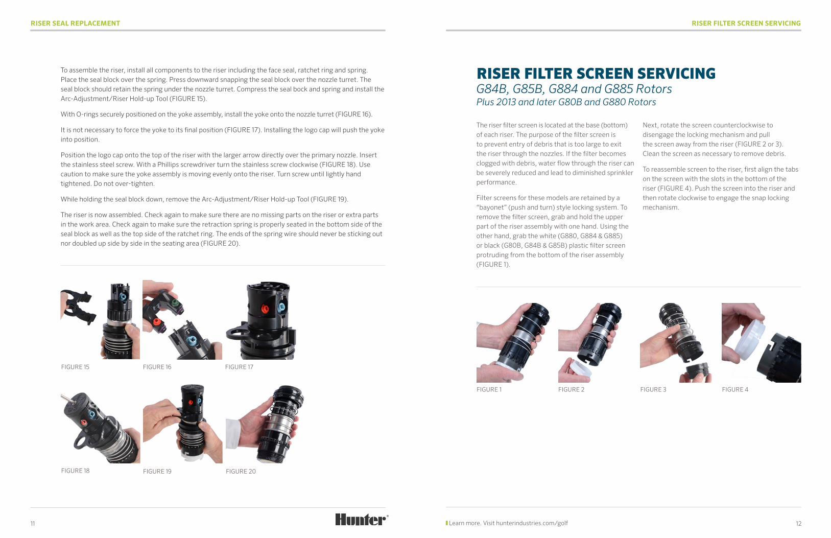
To assemble the riser, install all components to the riser including the face seal, ratchet ring and spring. Place the seal block over the spring. Press downward snapping the seal block over the nozzle turret. The seal block should retain the spring under the nozzle turret. Compress the seal bock and spring and install the Arc-Adjustment/Riser Hold-up Tool (FIGURE 15).
With O-rings securely positioned on the yoke assembly, install the yoke onto the nozzle turret (FIGURE 16).
It is not necessary to force the yoke to its final position (FIGURE 17). Installing the logo cap will push the yoke into position.
Position the logo cap onto the top of the riser with the larger arrow directly over the primary nozzle. Insert the stainless steel screw. With a Phillips screwdriver turn the stainless screw clockwise (FIGURE 18). Use caution to make sure the yoke assembly is moving evenly onto the riser. Turn screw until lightly hand tightened. Do not over-tighten.
While holding the seal block down, remove the Arc-Adjustment/Riser Hold-up Tool (FIGURE 19).
The riser is now assembled. Check again to make sure there are no missing parts on the riser or extra parts in the work area. Check again to make sure the retraction spring is properly seated in the bottom side of the seal block as well as the top side of the ratchet ring. The ends of the spring wire should never be sticking out nor doubled up side by side in the seating area (FIGURE 20).
11
FIGURE 17
FIGURE 20
FIGURE 16
FIGURE 19FIGURE 18
RISER FILTER SCREEN SERVICING
The riser filter screen is located at the base (bottom) of each riser. The purpose of the filter screen is to prevent entry of debris that is too large to exit the riser through the nozzles. If the filter becomes clogged with debris, water flow through the riser can be severely reduced and lead to diminished sprinkler performance.
Filter screens for these models are retained by a “bayonet” (push and turn) style locking system. To remove the filter screen, grab and hold the upper part of the riser assembly with one hand. Using the other hand, grab the white (G880, G884 & G885) or black (G80B, G84B & G85B) plastic filter screen protruding from the bottom of the riser assembly (FIGURE 1).
Next, rotate the screen counterclockwise to disengage the locking mechanism and pull the screen away from the riser (FIGURE 2 or 3). Clean the screen as necessary to remove debris.
To reassemble screen to the riser, first align the tabs on the screen with the slots in the bottom of the riser (FIGURE 4). Push the screen into the riser and then rotate clockwise to engage the snap locking mechanism.
FIGURE 1 FIGURE 2 FIGURE 3 FIGURE 4
RISER FILTER SCREEN SERVICING G84B, G85B, G884 and G885 Rotors Plus 2013 and later G80B and G880 Rotors
12 Learn more. Visit hunterindustries.com/golf
FIGURE 15
STATOR ADJUSTMENT
STATOR ADJUSTMENTS – WHY AND WHEN ARE THEY NEEDED?
The adjustable stator is preset at the factory to match the nozzle installed in the rotor. The purpose of the stator is to maintain a consistent and desirable speed of rotation. Rotors that turn too fast cannot reach their published radius distance. Rotors that turn too slowly will irrigate with a higher precipitation rate per revolution causing wet spots and run-off.
If nozzles are changed to a flow greater than the original factory nozzle, the speed of rotation will become faster unless the appropriate stator adjustments are made. This is because there is a greater amount of water passing the turbine that drives the gearbox. The opposite is true if a smaller flow nozzle is installed without adjusting the stator - the rotor will slow down. In extreme situations, the rotor may not rotate at all if the stator is not adjusted. Again, stator adjustments are not required unless the nozzle flow is being changed or, the stator was set incorrectly at some point in time.
Setting the stator is as simple as matching the stator setting number to the nozzle number being used in the rotor. For example, if the nozzle in use is #20, then the stator setting will be #20. To access the stator adjustment, first remove the riser’s filter screen as outlined in the previous section.
Remove the riser’s filter screen as described in the riser screen removal section of this manual. The G84 and G85 rotors have stator assemblies that are removable from the riser assembly. When the filter screen is removed, the stator assembly will sometimes remain in the riser assembly next to the turbine. Other times the stator assembly will stay in the filter screen’s nest as the screen is removed from the riser. Or, the screen can fall to the ground as the screen is removed.
IDENTIFYING YOUR STATOR ASSEMBLY
There are two types of stator assemblies for these rotors. The correct one to use is based upon which of the primary nozzles is installed in the riser assembly.
13
FIGURE 1 FIGURE 2 FIGURE 3
STATOR ADJUSTMENT
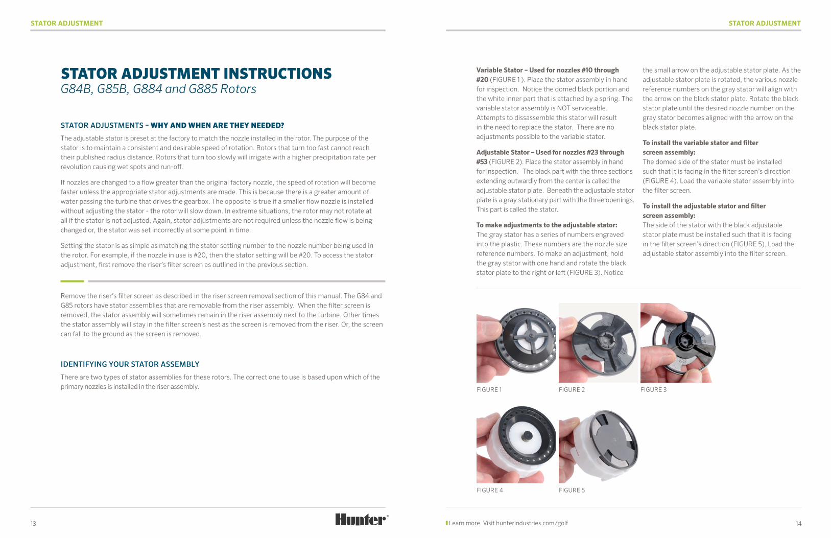
Variable Stator – Used for nozzles #10 through #20 (FIGURE 1 ). Place the stator assembly in hand for inspection. Notice the domed black portion and the white inner part that is attached by a spring. The variable stator assembly is NOT serviceable. Attempts to dissassemble this stator will result in the need to replace the stator. There are no adjustments possible to the variable stator.
Adjustable Stator – Used for nozzles #23 through #53 (FIGURE 2). Place the stator assembly in hand for inspection. The black part with the three sections extending outwardly from the center is called the adjustable stator plate. Beneath the adjustable stator plate is a gray stationary part with the three openings. This part is called the stator.
To make adjustments to the adjustable stator: The gray stator has a series of numbers engraved into the plastic. These numbers are the nozzle size reference numbers. To make an adjustment, hold the gray stator with one hand and rotate the black stator plate to the right or left (FIGURE 3). Notice
the small arrow on the adjustable stator plate. As the adjustable stator plate is rotated, the various nozzle reference numbers on the gray stator will align with the arrow on the black stator plate. Rotate the black stator plate until the desired nozzle number on the gray stator becomes aligned with the arrow on the black stator plate.
To install the variable stator and filter screen assembly: The domed side of the stator must be installed such that it is facing in the filter screen’s direction (FIGURE 4). Load the variable stator assembly into the filter screen.
To install the adjustable stator and filter screen assembly: The side of the stator with the black adjustable stator plate must be installed such that it is facing in the filter screen’s direction (FIGURE 5). Load the adjustable stator assembly into the filter screen.
FIGURE 4
STATOR ADJUSTMENT INSTRUCTIONS G84B, G85B, G884 and G885 Rotors
14 Learn more. Visit hunterindustries.com/golf
FIGURE 5
STATOR ADJUSTMENT
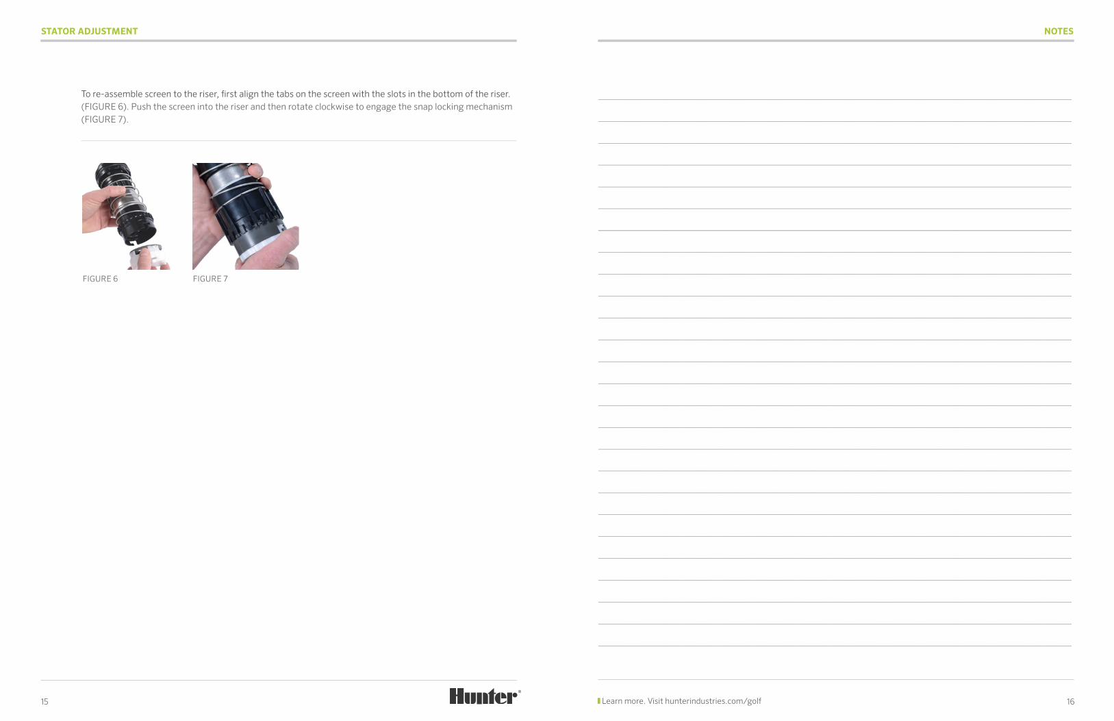
To re-assemble screen to the riser, first align the tabs on the screen with the slots in the bottom of the riser.(FIGURE 6). Push the screen into the riser and then rotate clockwise to engage the snap locking mechanism (FIGURE 7).
15
FIGURE 6 FIGURE 7
NOTES
16 Learn more. Visit hunterindustries.com/golf
________________________________________________________________________________________
________________________________________________________________________________________
________________________________________________________________________________________
________________________________________________________________________________________
________________________________________________________________________________________
________________________________________________________________________________________
________________________________________________________________________________________
________________________________________________________________________________________
________________________________________________________________________________________
________________________________________________________________________________________
________________________________________________________________________________________
________________________________________________________________________________________
________________________________________________________________________________________
________________________________________________________________________________________
________________________________________________________________________________________
________________________________________________________________________________________
________________________________________________________________________________________
________________________________________________________________________________________
________________________________________________________________________________________
________________________________________________________________________________________
________________________________________________________________________________________
________________________________________________________________________________________
________________________________________________________________________________________
________________________________________________________________________________________
________________________________________________________________________________________
________________________________________________________________________________________
© 2014 Hunter Industries Incorporated Please recycle. GLIT-071 A 4/14
This brochure was printed on Forest Stewardship Council® (FSC) certified paper with soy inks. The FSC is an international organization established to promote the responsible management of the world’s forests.
Website hunterindustries.com | Customer Support 1-800-383-4747 | Technical Support 1-800-733-2823
Printed using 100% Wind Energy, (RECs)