Embed Size (px)
Citation preview

ACC2 DecoderBUILT TO COMMANDEVEN THE LARGEST PROJECTS
Quick Start Guide

2 hunter.direct/ACC2help
POWERFUL. INTELLIGENT. FLEXIBLE. THE ACC2 CONTROLLER DELIVERS ADVANCED WATER MANAGEMENT TO MEET THE DEMANDS OF LARGE-SCALE COMMERCIAL PROJECTS.
TABLE OF CONTENTSACC2 Decoders ................................................... 4
Important Connections and Tips .................. 4Facepack ............................................................... 4Reversing the Facepack .................................... 4Connecting and Disconnecting the Facepack .5SyncPort™ Connection ......................................5SD Card Reader ...................................................5Battery..................................................................5
External Components ......................................... 6Front Door ........................................................... 6Face Frame .......................................................... 6Facepack.............................................................. 6Face Frame Latch ............................................... 6Facepack Cable ................................................... 6Spare Decoder Fuses and Tool ......................... 6Spare Fuse Holders ............................................ 6Wall Mount Bracket ........................................... 6Wire Ties for Strain Relief .................................. 6
Internal Components .......................................... 6PCU Board ........................................................... 6Slide Lock ............................................................ 6Output Module Slots ......................................... 6Flow Expansion Slot ........................................... 6Earth Ground Lug ............................................... 6Transformer Assembly ...................................... 6Wiring Compartment Cover ............................. 6Power Supply Board .......................................... 6Flow Sensor Inputs............................................. 6Status Light ......................................................... 6Programming Port ............................................. 6Decoder Output Module Lights ....................... 8Wire Ties .............................................................. 8Transformer Fuse ............................................... 8Flow Expansion Module .................................... 8
Field Wiring .......................................................... 9
Operating the Controls ...................................10
Attention Messages ........................................10Start-Up Screen ..................................................10View Messages ....................................................11Clear Messages ...................................................11View Logs .............................................................11
Home and Activity Screens ............................11Activity Screen....................................................12
Basic Programming and Setup ....................13Names ..................................................................13
hunter.direct/acc2 1-800-733-2823
Troubleshooting Need more helpful information on your product? Find tips on installation, controller programming, and more.

Built on Innovation® 3
Settings, Time/Date .........................................13Pump/Master Valve Setup ...............................14Manual Starts and Test .....................................15Stop Commands .................................................15Programs .............................................................16Start Times .........................................................16
Intelligent Current Sensing ............................ 17Run Times .......................................................... 17Water Days ........................................................18Seasonal Adjust .................................................18Program Rules ...................................................19
Ignore Calendar Days Off ...............................19No Water Window (Start and End)................19Station Delay (Delay Between Stations) ......19
Calendar Days Off ..............................................19Program Summary ...........................................19
P/MV Operation (Pump/Master Valve Operation) ..........................................................20Sensors ...............................................................20Clik Sensors .......................................................20Sensor Response ...............................................21Solar Sync® ........................................................ 22Flow Sensors ..................................................... 22
Stations Menu .................................................. 23Station Setup ..................................................... 23Cycle & Soak .......................................................24Blocks ..................................................................24Station Limits ..................................................... 25Station Summary .............................................. 25
Devices Menu ................................................... 26P/MV Operation ................................................ 26Flow Sensors ...................................................... 26Solar Sync® ......................................................... 26Clik Sensors ........................................................ 26Sensor Response ............................................... 26
Flow Menu ......................................................... 27Clear Flow Alarms ............................................. 27
Settings Menu ................................................. 27Time/Date ......................................................... 27Regional Settings .............................................. 27User Management ............................................ 28Networking ....................................................... 28
Diagnostics Menu............................................ 29View Logs ........................................................... 29Alarm Logs ........................................................ 29Controller Logs ................................................ 29
Station Logs ......................................................30Filter Logs ..........................................................30Export Logs .......................................................30
Module Info ........................................................30Clik Sensor Diagnostics ...................................30Station-P/MV Diagnostics ...............................31Flow Sensor Diagnostics ..................................31Solar Sync Diagnostics .....................................31Decoder Diagnostics .........................................31
Advanced Features ......................................... 32Export Logs ........................................................ 32Easy Retrieve ..................................................... 32Reset Memory ................................................... 33Firmware Update .............................................. 33Conditional Response ....................................... 33
Flow Operations ...............................................34Flow Manager ....................................................34Flow Monitor ......................................................34MainSafe™ ........................................................34Set Up Flow Monitor ......................................... 35Flow Zones ........................................................ 35
Flow Map ......................................................... 35Flow Limits ...................................................... 36Flow Allowances ............................................. 36
Station Setup .................................................... 37Station P/MV Usage ...................................... 37Flow Zone ........................................................ 37Flow Priority .................................................... 37Flow Measurement Settings ........................ 37Copy and Paste ............................................... 37
Learn Flow ......................................................... 38Schedule Flow Learning ................................ 38
Hydraulic Summary ......................................... 39Flow Totals ........................................................ 39View Flow ..........................................................40
Flow Alarm Handling ........................................40Station-Level Alarms ........................................41Flow Zone or MainSafe™ Alarms .....................41
Set Up Flow Manager .......................................42Flow Zones ........................................................42
Flow Target ......................................................42Station Setup ....................................................43
Flow Zone ........................................................43Flow Priority ......................................................43
Flow Rate .........................................................43Station Limits ....................................................44
MainSafe™ .........................................................44
Setup Screen ....................................................45Flow Limits Screen ...........................................45
Maximum Flow ...............................................45Unscheduled Flow ..........................................45Alarm Delay .....................................................45Alarm Clear Delay ...........................................45
Allowances Screen ...........................................46Monthly Budget .............................................46Manual Watering Allowance .........................46
Conditional Response .................................... 47Set up a Conditional Response .......................48Conditional Response Types ...........................49SOS (Status Output Station) ...........................50
Set up an SOS station ....................................50Start Stations, Programs, and Blocks ............50
Mode ................................................................50Switch P/MVs ....................................................51
Decoders Menu ................................................ 52Program Decoder .............................................. 52Serial Number ................................................... 52Decoder Type .................................................... 52Power Factor ..................................................... 52Inrush ................................................................. 52Output-Station ................................................. 52Programming Station Decoders ................... 53Programming Pump/Master Valve (PMV) Decoders .......................................................... 53Programming Sensor Decoders ....................54Programming Decoders via the Two-Wire Path ....................................................................54
View Configuration ........................................... 55View Status ........................................................ 55Decoder View .................................................... 55
Station Assignments ........................................ 56Decoder Diagnostics ......................................... 56Station Finder ................................................... 56Wire Test ........................................................... 57
Decoder Inventory ............................................ 57Filter ................................................................... 58Comm % ............................................................. 58Update Available .............................................. 58Export Inventory .............................................. 58
Refresh Inventory ........................................... 58Clear Inventory ................................................. 58
Update Decoders ............................................... 58
Troubleshooting ............................................... 59
4 hunter.direct/ACC2help
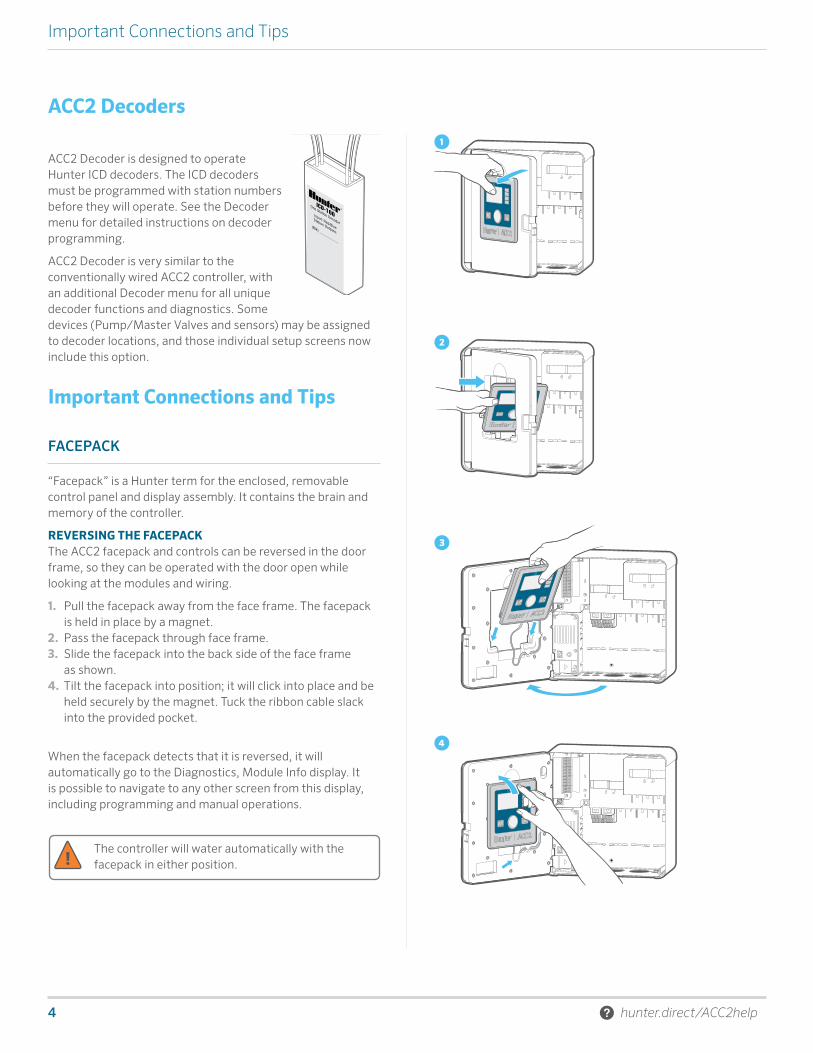
Important Connections and Tips
①
②
③
④
ACC2 Decoders
ACC2 Decoder is designed to operate Hunter ICD decoders. The ICD decoders must be programmed with station numbers before they will operate. See the Decoder menu for detailed instructions on decoder programming.
ACC2 Decoder is very similar to the conventionally wired ACC2 controller, with an additional Decoder menu for all unique decoder functions and diagnostics. Some devices (Pump/Master Valves and sensors) may be assigned to decoder locations, and those individual setup screens now include this option.
Important Connections and Tips
FACEPACK
“Facepack” is a Hunter term for the enclosed, removable control panel and display assembly. It contains the brain and memory of the controller.
REVERSING THE FACEPACKThe ACC2 facepack and controls can be reversed in the door frame, so they can be operated with the door open while looking at the modules and wiring.
1. Pull the facepack away from the face frame. The facepack is held in place by a magnet.
2. Pass the facepack through face frame.3. Slide the facepack into the back side of the face frame
as shown. 4. Tilt the facepack into position; it will click into place and be
held securely by the magnet. Tuck the ribbon cable slack into the provided pocket.
When the facepack detects that it is reversed, it will automatically go to the Diagnostics, Module Info display. It is possible to navigate to any other screen from this display, including programming and manual operations.
The controller will water automatically with the facepack in either position.

Built on Innovation® 5
Important Connections and Tips
①
②
CONNECTING AND DISCONNECTING THE FACEPACKThe facepack cable connection is located just below the light on the Power Supply Board. Turn power to controller off before connecting or disconnecting the facepack.
SYNCPORT™ CONNECTION The SyncPort connection is a proprietary Hunter connection for external interface devices. It is located near the top of the Power Supply Module.
① SyncPort
② Facepack Cable Connection
Do not attempt to connect the facepack cable to this port. The connector has a protective cover that should be left in place until the connection is needed.
If power to the controller is left off for extended periods, the battery will be consumed more quickly.
Consult the connecting device’s manual for additional instructions regarding SyncPort.
SD CARD READERThe bottom edge of the facepack includes a built-in SD card reader. The controller is supplied with an SD card.
The SD card can:
• Upload updated firmware (saved from email or the hunterindustries.com website) to the controller and all its modules.
• Store logs, Easy Retrieve backups, and other information for use later or on another device. See the Advanced Features menu on page 32.
BATTERYThe facepack has a replaceable internal lithium battery in the side of the facepack to back up date and time settings during power outages (Program settings and other data are non-volatile and do not require battery backup). The battery may last the life of the controller, but is easily replaced if necessary.
Use a standard CR2032 replacement if necessary. Be sure to place the + side of the battery correctly.
6 hunter.direct/ACC2help
Components
⑤ ➎
⑥
①
②
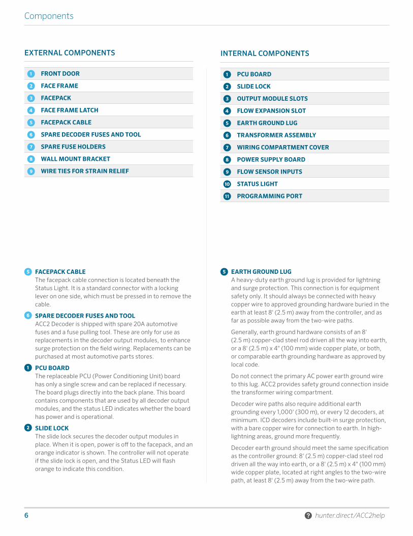
EXTERNAL COMPONENTS
① FRONT DOOR
② FACE FRAME
③ FACEPACK
④ FACE FRAME LATCH
⑤ FACEPACK CABLE
⑥ SPARE DECODER FUSES AND TOOL
➐ SPARE FUSE HOLDERS
➑ WALL MOUNT BRACKET
➒ WIRE TIES FOR STRAIN RELIEF
FACEPACK CABLEThe facepack cable connection is located beneath the Status Light. It is a standard connector with a locking lever on one side, which must be pressed in to remove the cable.
SPARE DECODER FUSES AND TOOLACC2 Decoder is shipped with spare 20A automotive fuses and a fuse pulling tool. These are only for use as replacements in the decoder output modules, to enhance surge protection on the field wiring. Replacements can be purchased at most automotive parts stores.
PCU BOARDThe replaceable PCU (Power Conditioning Unit) board has only a single screw and can be replaced if necessary. The board plugs directly into the back plane. This board contains components that are used by all decoder output modules, and the status LED indicates whether the board has power and is operational.
SLIDE LOCKThe slide lock secures the decoder output modules in place. When it is open, power is off to the facepack, and an orange indicator is shown. The controller will not operate if the slide lock is open, and the Status LED will flash orange to indicate this condition.
EARTH GROUND LUGA heavy-duty earth ground lug is provided for lightning and surge protection. This connection is for equipment safety only. It should always be connected with heavy copper wire to approved grounding hardware buried in the earth at least 8' (2.5 m) away from the controller, and as far as possible away from the two-wire paths.
Generally, earth ground hardware consists of an 8' (2.5 m) copper-clad steel rod driven all the way into earth, or a 8' (2.5 m) x 4" (100 mm) wide copper plate, or both, or comparable earth grounding hardware as approved by local code.
Do not connect the primary AC power earth ground wire to this lug. ACC2 provides safety ground connection inside the transformer wiring compartment.
Decoder wire paths also require additional earth grounding every 1,000' (300 m), or every 12 decoders, at minimum. ICD decoders include built-in surge protection, with a bare copper wire for connection to earth. In high-lightning areas, ground more frequently.
Decoder earth ground should meet the same specification as the controller ground: 8' (2.5 m) copper-clad steel rod driven all the way into earth, or a 8' (2.5 m) x 4" (100 mm) wide copper plate, located at right angles to the two-wire path, at least 8' (2.5 m) away from the two-wire path.
INTERNAL COMPONENTS
① PCU BOARD
② SLIDE LOCK
③ OUTPUT MODULE SLOTS
④ FLOW EXPANSION SLOT
⑤ EARTH GROUND LUG
➏ TRANSFORMER ASSEMBLY
⑦ WIRING COMPARTMENT COVER
⑧ POWER SUPPLY BOARD
⑨ FLOW SENSOR INPUTS
⑩ STATUS LIGHT
⑪ PROGRAMMING PORT
Built on Innovation® 7
Components
➒ ⓫
➓⑧
① ② ③ ④ ⑤ ① ⑩⑪
⑤
⑥⑧⑨ ⑦
②③
④
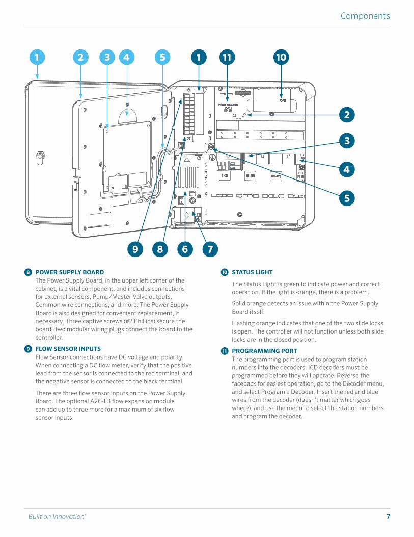
POWER SUPPLY BOARDThe Power Supply Board, in the upper left corner of the cabinet, is a vital component, and includes connections for external sensors, Pump/Master Valve outputs, Common wire connections, and more. The Power Supply Board is also designed for convenient replacement, if necessary. Three captive screws (#2 Phillips) secure the board. Two modular wiring plugs connect the board to the controller.
FLOW SENSOR INPUTSFlow Sensor connections have DC voltage and polarity. When connecting a DC flow meter, verify that the positive lead from the sensor is connected to the red terminal, and the negative sensor is connected to the black terminal.
There are three flow sensor inputs on the Power Supply Board. The optional A2C-F3 flow expansion module can add up to three more for a maximum of six flow sensor inputs.
STATUS LIGHT
The Status Light is green to indicate power and correct operation. If the light is orange, there is a problem.
Solid orange detects an issue within the Power Supply Board itself.
Flashing orange indicates that one of the two slide locks is open. The controller will not function unless both slide locks are in the closed position.
PROGRAMMING PORTThe programming port is used to program station numbers into the decoders. ICD decoders must be programmed before they will operate. Reverse the facepack for easiest operation, go to the Decoder menu, and select Program a Decoder. Insert the red and blue wires from the decoder (doesn’t matter which goes where), and use the menu to select the station numbers and program the decoder.

8 hunter.direct/ACC2help
Decoder Wiring and Tips
DECODER OUTPUT MODULE LIGHTSEach decoder output module is equipped with diagnostic LED lights. Each light is labeled on the deck lid.
Symbol Activity Type Color and Meaning
Decoder faultBlinking red: Decoder has an over-current or overload
Module or line activity
Blinking green: Station active
Blinking red: Line overload (wire path short) Also blinks during decoder update
Communicating
Blinking green: Two-wire communications
Blinking amber: Programming port communications
Solid amber: Wire test mode
Line status
Blinking green: Module damaged (replace)
Solid green: Line is OK
Off: No power to module
WIRE TIESWire tie holders are molded into the lower back of the wiring compartment to secure field wiring with plastic zip ties. This provides a strain relief to keep field wires from pulling downward on the modules, and keeps the inside neat and organized.
Additional wire tie holders are provided near the Power Supply Board for sensor and other connections.
TRANSFORMER FUSEThe transformer uses a replaceable 5 x 20 mm electrical fuse, located next to the convenient on/off switch. Two spare fuses are stored in the bottom rear of the facepack frame, under the sticker labeled “Spare Fuse.”
Replacement fuses are a standard glass body 5 x 20 mm 250V, 2A fast blow, available online or from electronic appliance retailers and hardware stores.
FLOW EXPANSION MODULEA2C-F3 flow expansion modules add three additional hardwired flow inputs to the controller. These modules may only be added to the lower right module slot, one per controller, and it is the only module that will fit in this slot.
The flow expansion module has DC voltage and polarity, and the + (or red) connection from the flow sensor must be connected correctly to the + (positive) terminals on the module. Finish flow expansion in the Devices, Flow Sensors menu after installing the module.
ACC2 Decoder controllers may also read up to six flow sensors via the two-wire paths using ICD-SEN sensor decoders. The controller may use any combination of hardwired inputs to flow terminals, or connection by sensor decoders.
Built on Innovation® 9
Decoder Wiring and Tips
FIELD WIRING
Proper installation and connection of the decoder two-wire paths is very important.
• Use only Hunter IDWIRE or an approved substitute.• Use only Hunter DBRY-6 waterproof connectors in the red
and blue two-wire path connections. • Leave adequate slack (about 5' or 1.5 m) at each splice, to
prevent disconnection.
Each A2C-D75 output module supports up to 75 decoder stations.
• Each module allows up to three two-wire path connections. • Each path may be up to 10,000' (3 km) with 14 AWG
(2 mm2) wire, or up to 15,000' (4.5 km) with 12 AWG (approximately 3.31 mm2) wire.
• Two-wire paths may be tee-spliced (in a valve box with approved connectors), as long as the maximum distance to each end of the paths from the controller does not exceed the maximum for the wire used.
You can have more than 75 stations on a single two-wire path. If more than one A2C-D75 is installed, it is possible to assign the additional station numbers to another decoder output module. This must be done with the Station Assignments function on the Decoder menu, so the controller will know which module has the additional stations.
10 hunter.direct/ACC2help
Operating the Controls
①
②
③ ④
Operating the Controls
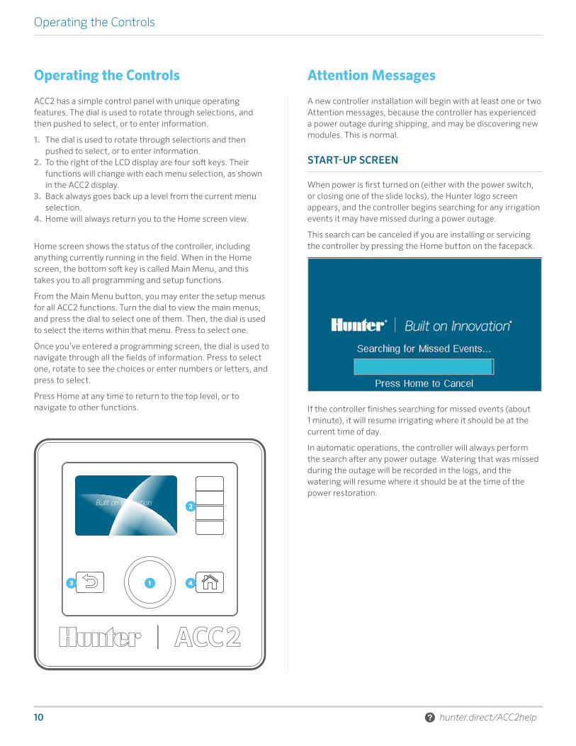
ACC2 has a simple control panel with unique operating features. The dial is used to rotate through selections, and then pushed to select, or to enter information.
1. The dial is used to rotate through selections and then pushed to select, or to enter information.
2. To the right of the LCD display are four soft keys. Their functions will change with each menu selection, as shown in the ACC2 display.
3. Back always goes back up a level from the current menu selection.
4. Home will always return you to the Home screen view.
Home screen shows the status of the controller, including anything currently running in the field. When in the Home screen, the bottom soft key is called Main Menu, and this takes you to all programming and setup functions.
From the Main Menu button, you may enter the setup menus for all ACC2 functions. Turn the dial to view the main menus, and press the dial to select one of them. Then, the dial is used to select the items within that menu. Press to select one.
Once you’ve entered a programming screen, the dial is used to navigate through all the fields of information. Press to select one, rotate to see the choices or enter numbers or letters, and press to select.
Press Home at any time to return to the top level, or to navigate to other functions.
Attention Messages
A new controller installation will begin with at least one or two Attention messages, because the controller has experienced a power outage during shipping, and may be discovering new modules. This is normal.
START-UP SCREEN
When power is first turned on (either with the power switch, or closing one of the slide locks), the Hunter logo screen appears, and the controller begins searching for any irrigation events it may have missed during a power outage.
This search can be canceled if you are installing or servicing the controller by pressing the Home button on the facepack.
If the controller finishes searching for missed events (about 1 minute), it will resume irrigating where it should be at the current time of day.
In automatic operations, the controller will always perform the search after any power outage. Watering that was missed during the outage will be recorded in the logs, and the watering will resume where it should be at the time of the power restoration.
Built on Innovation® 11
Home and Activity Screens
VIEW MESSAGES
Messages on the screen do not interfere with normal irrigation.
A flashing alarm symbol at the bottom of the display indicates that something unusual has been detected. When the symbol is flashing, a soft key will link to View Messages. Press the key to view the most recent messages in the Attention screen.
From the Attention screen, you can View Logs to get more details about the messages and/or Clear Messages to return to the Home screen.
CLEAR MESSAGES
Attention messages in the display can be cleared by pressing the Clear Messages soft key, after pressing View Messages. The message will still be available in the controller’s logs.
Attention messages do not prevent watering or normal operation. However, they may announce a condition that can prevent or affect watering.
VIEW LOGS
Press View Logs for more detailed information about each message.
The soft keys will link to the Alarm, Controller, and Station logs when an attention message is displayed. The Filter Logs function will allow you to search for logs on a specific date, or by record number. You can also access logs at any time from the Diagnostics menu.
Home and Activity Screens
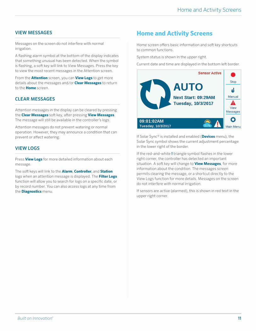
Home screen offers basic information and soft key shortcuts to common functions.
System status is shown in the upper right.
Current date and time are displayed in the bottom left border.
If Solar Sync® is installed and enabled (Devices menu), the Solar Sync symbol shows the current adjustment percentage in the lower right of the border.
If the red-and-white ! triangle symbol flashes in the lower right corner, the controller has detected an important situation. A soft key will change to View Messages, for more information about the condition. The messages screen permits clearing the message, or a shortcut directly to the View Logs function for more details. Messages on the screen do not interfere with normal irrigation.
If sensors are active (alarmed), this is shown in red text in the upper right corner.
12 hunter.direct/ACC2help
Home and Activity Screens
ACTIVITY SCREEN
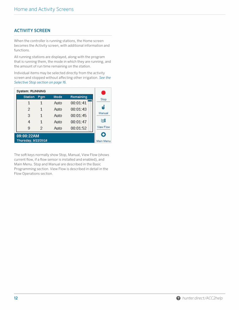
When the controller is running stations, the Home screen becomes the Activity screen, with additional information and functions.
All running stations are displayed, along with the program that is running them, the mode in which they are running, and the amount of run time remaining on the station.
Individual items may be selected directly from the activity screen and stopped without affecting other irrigation. See the Selective Stop section on page 16.
The soft keys normally show Stop, Manual, View Flow (shows current flow, if a flow sensor is installed and enabled), and Main Menu. Stop and Manual are described in the Basic Programming section. View Flow is described in detail in the Flow Operations section.

Built on Innovation® 13
Basic Programming and Setup
SETTINGS, TIME/DATE
From the Home screen, press Main Menu, and dial to Settings.
Select Settings, and dial to Regional Settings.
Choose language, time and date formats, and units of measurement. Press Back or Home to exit.
From the Settings menu, choose Time/Date: Set the current time and date, and also Daylight Saving options. Press Back or Home to exit.
Basic Programming and Setup
NAMES
ACC2 allows items to be named with an on-screen keyboard that appears in the Name field (or from a mobile device, if the optional Wi-Fi module is installed). Names are useful in large systems, especially in the more advanced Flow Operations.
Select the Name field for any of these components, and a keyboard will appear to enter an alphanumeric name.
Items that can be named are:
• Programs• Stations• Blocks• Clik Sensors• MainSafe™ zones• Flow Zones

14 hunter.direct/ACC2help
Basic Programming and Setup
PUMP/MASTER VALVE SETUP
In the decoder controller, P/MV outputs can be assigned to either direct terminals in the controller, or to ICD-100 station decoders.
P/MV outputs 1 through 3 refer to the output terminals on the Power Supply Board, unless they are changed to decoder locations. P/MV outputs 4, 5, and 6 must be assigned to decoders.
All P/MV outputs are set to Normally Closed operation, but they can be changed to Normally Open functions in the Devices menu. See the P/MV Operation section on page 20.

Built on Innovation® 15
Basic Programming and Setup
MANUAL STARTS AND TEST
On the Home screen, the Manual soft key lets you start stations, programs, or a Test program. Once you press Manual, there are three choices:
MANUAL STATIONSSpecify one or more stations to run and enter a run time for them. You can also choose to run them simultaneously, rather than sequentially, if you check the Simultaneous box. Press the Start key to start the list.
MANUAL PROGRAMSelect a program number to start, and press the Start key to start it. It is also possible to scroll down to an event in the program, and start the program from that point forward.
A Manual Station or Program Start will pause any automatic watering until the Manual Program has completed.
TEST PROGRAMThe Test program will run all stations in the controller for the Run Time entered on the screen. It is also possible to specify a station number, and run all remaining stations from that number to the highest numbered station.
In the ACC2 Decoder controller, the Test Program will only run stations that already have a run time in other programs in the controller.
STOP COMMANDS
Any running irrigation can be stopped immediately from the Home screen. The top soft key offers the following choices for stopping irrigation:
STOP ALL IRRIGATIONThis immediately stops everything that is watering or running. The controller is still in Automatic irrigation mode, and will resume watering at the next start time.
TIMED OFFLike System Off, this stops all stations and prevents automatic irrigation, but for a specified period of days. When the days have counted down to zero, the controller will resume automatic operations.
PAUSEThis interrupts whatever is currently running, until either Resume is pressed or 30 minutes have passed. Anything running will be resumed where it left off, and run for its remaining time. When items are paused, the Resume button will appear.
SYSTEM OFFThis turns off all irrigation, and places the controller in permanent Off mode. No automatic irrigation will occur.
16 hunter.direct/ACC2help
Basic Programming and Setup
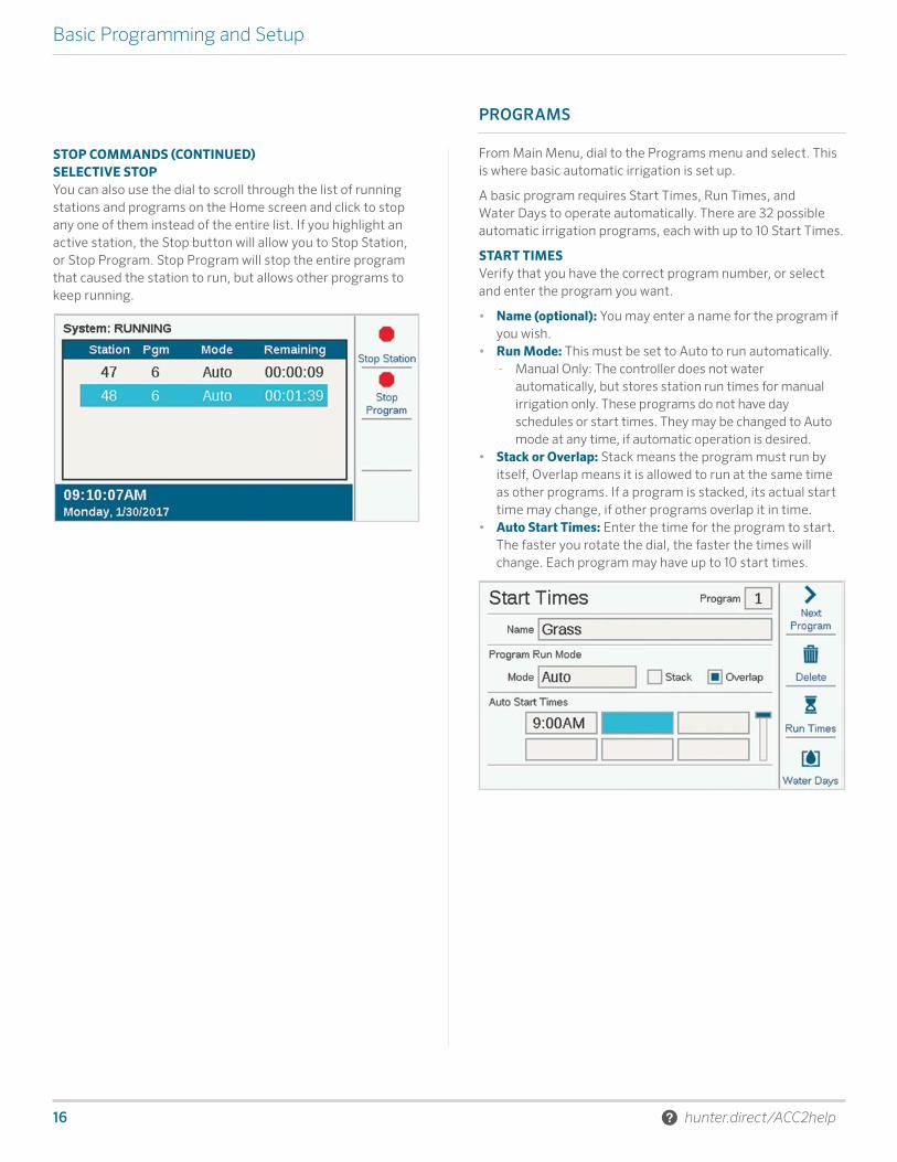
STOP COMMANDS (CONTINUED)SELECTIVE STOPYou can also use the dial to scroll through the list of running stations and programs on the Home screen and click to stop any one of them instead of the entire list. If you highlight an active station, the Stop button will allow you to Stop Station, or Stop Program. Stop Program will stop the entire program that caused the station to run, but allows other programs to keep running.
PROGRAMS
From Main Menu, dial to the Programs menu and select. This is where basic automatic irrigation is set up.
A basic program requires Start Times, Run Times, and Water Days to operate automatically. There are 32 possible automatic irrigation programs, each with up to 10 Start Times.
START TIMESVerify that you have the correct program number, or select and enter the program you want.
• Name (optional): You may enter a name for the program if you wish.
• Run Mode: This must be set to Auto to run automatically. - Manual Only: The controller does not water
automatically, but stores station run times for manual irrigation only. These programs do not have day schedules or start times. They may be changed to Auto mode at any time, if automatic operation is desired.
• Stack or Overlap: Stack means the program must run by itself, Overlap means it is allowed to run at the same time as other programs. If a program is stacked, its actual start time may change, if other programs overlap it in time.
• Auto Start Times: Enter the time for the program to start. The faster you rotate the dial, the faster the times will change. Each program may have up to 10 start times.
Built on Innovation® 17
Basic Programming and Setup
INTELLIGENT CURRENT SENSINGACC2 has no artificial programming limits preventing overlapping programs and stations. The controller senses how much electrical current is being drawn, and will suspend stations automatically if the combined current threatens the transformer.
It is also possible to set Controller and Station Limits (Stations, Station Limits) to control how many outputs may operate at once.
An ACC2 Decoder controller may run as many as 20 Hunter solenoids per module (including any P/MV outputs) simultaneously, and up to 30 per controller (when multiple output modules are installed) before suspending additional stations. Environmental factors or higher-draw solenoids may cause the overcurrent protection to activate at lower station counts.
It is possible to view the current draw of each decoder output module in the Decoder Diagnostics screen.
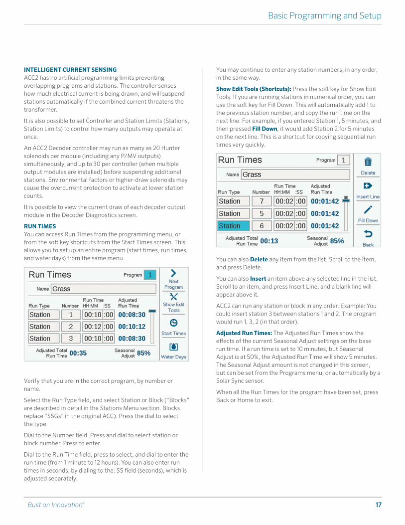
RUN TIMESYou can access Run Times from the programming menu, or from the soft key shortcuts from the Start Times screen. This allows you to set up an entire program (start times, run times, and water days) from the same menu.
Verify that you are in the correct program, by number or name.
Select the Run Type field, and select Station or Block (“Blocks” are described in detail in the Stations Menu section. Blocks replace “SSGs” in the original ACC). Press the dial to select the type.
Dial to the Number field. Press and dial to select station or block number. Press to enter.
Dial to the Run Time field, press to select, and dial to enter the run time (from 1 minute to 12 hours). You can also enter run times in seconds, by dialing to the: SS field (seconds), which is adjusted separately.
You may continue to enter any station numbers, in any order, in the same way.
Show Edit Tools (Shortcuts): Press the soft key for Show Edit Tools. If you are running stations in numerical order, you can use the soft key for Fill Down. This will automatically add 1 to the previous station number, and copy the run time on the next line. For example, if you entered Station 1, 5 minutes, and then pressed Fill Down, it would add Station 2 for 5 minutes on the next line. This is a shortcut for copying sequential run times very quickly.
You can also Delete any item from the list. Scroll to the item, and press Delete.
You can also Insert an item above any selected line in the list. Scroll to an item, and press Insert Line, and a blank line will appear above it.
ACC2 can run any station or block in any order. Example: You could insert station 3 between stations 1 and 2. The program would run 1, 3, 2 (in that order).
Adjusted Run Times: The Adjusted Run Times show the effects of the current Seasonal Adjust settings on the base run time. If a run time is set to 10 minutes, but Seasonal Adjust is at 50%, the Adjusted Run Time will show 5 minutes. The Seasonal Adjust amount is not changed in this screen, but can be set from the Programs menu, or automatically by a Solar Sync sensor.
When all the Run Times for the program have been set, press Back or Home to exit.

18 hunter.direct/ACC2help
Basic Programming and Setup
WATER DAYS Verify you are in the correct program by number or name, and set the days for automatic watering.
Mode selects a type of schedule.
• Day of Week: Check the boxes for the days the program should water.
• Odd/Even: Water only on odd or even calendar dates, to comply with water restrictions. An optional check box allows skipping the 31st day of the month.
• Interval: Water every “x” number of days, regardless of the day of week. Enter the desired interval days.
Both Odd/Even and Interval also have Non-Water Days, which can set a day (for example, a mowing day) on which watering will never occur, regardless of the schedule.
SEASONAL ADJUSTPrograms menu, Seasonal Adjust.
When using Solar Sync, set up at Devices page first, then go to Seasonal Adjust.
• Seasonal Adjust Mode: Set a percentage adjustment to all run times by Controller or Program, or set a Monthly schedule for the controller to follow automatically, or assign the program to Solar Sync automatic adjustment.
• Controller: The Seasonal Adjust value will follow whatever has been set for the controller level. All programs set to Controller will receive the same manual adjustment.
• Program: The Season Adjust factor entered here will only apply to the selected program, and is not affected by other adjustments.
• Monthly: Enter in advance the adjustment value for each month of the year (usually based on historical weather averages). These adjustments take effect automatically on the 1st of each month, and do not change during the month.
• Solar Sync: Adjustments are made to the selected program automatically by a Solar Sync sensor attached to the controller. This requires a sensor, and setup at the Devices menu, Setup Solar Sync.
Each Program must have a Seasonal Adjustment set. Copy and Paste shortcuts permit copying the initial setup, and then pasting it to all similar programs.

Built on Innovation® 19
Basic Programming and Setup
PROGRAM RULESProgram Rules customizes each program for special purposes.
IGNORE CALENDAR DAYS OFFCheck the box if the program should be allowed to run on Calendar Days Off that apply to other programs.
NO WATER WINDOW (START AND END)Enter start and end times for the portion of the day during which automatic irrigation is never allowed. Program will never be allowed to run during this period, although Manual operations will be allowed. If a program is suspended by a No Water Window, it will be logged as an alarm, for corrective action.
STATION DELAY (DELAY BETWEEN STATIONS)Sets an interval between each station in a program. This can be used for slow-closing valves, recharging pressure tanks, etc. During the delay, the P/MV output will continue running for 15 seconds, unless this is adjusted in the Devices, P/MV Operation screen.
CALENDAR DAYS OFFCreate a list of dates on which the whole controller will not be allowed to run, regardless of Water Day settings. Programs that have been set to Ignore Calendar Days Off in the Program Rules screen will be allowed to run anyway.
PROGRAM SUMMARYOnce a program has start times, run times, and water days, it will run automatically without further setup. To see how the program is configured, select Program Summary from the Programming screen.
The Summary will show the total number of Programs ready to run for the entire controller.
Press the Programs soft key to view details for each program.
Press the Graph soft key to view a chart of all programs occurring over time. Turn the dial to view the graph up to 7 days in advance.
Non-Water Windows and Calendar Days Off options will show on the graph in red as Water Restrictions, meaning automatic irrigation cannot occur during those periods.
20 hunter.direct/ACC2help
Basic Programming and Setup
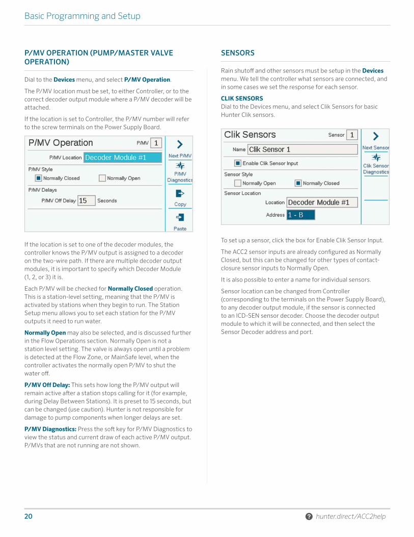
P/MV OPERATION (PUMP/MASTER VALVE OPERATION)
Dial to the Devices menu, and select P/MV Operation.
The P/MV location must be set, to either Controller, or to the correct decoder output module where a P/MV decoder will be attached.
If the location is set to Controller, the P/MV number will refer to the screw terminals on the Power Supply Board.
If the location is set to one of the decoder modules, the controller knows the P/MV output is assigned to a decoder on the two-wire path. If there are multiple decoder output modules, it is important to specify which Decoder Module (1, 2, or 3) it is.
Each P/MV will be checked for Normally Closed operation. This is a station-level setting, meaning that the P/MV is activated by stations when they begin to run. The Station Setup menu allows you to set each station for the P/MV outputs it need to run water.
Normally Open may also be selected, and is discussed further in the Flow Operations section. Normally Open is not a station level setting. The valve is always open until a problem is detected at the Flow Zone, or MainSafe level, when the controller activates the normally open P/MV to shut the water off.
P/MV Off Delay: This sets how long the P/MV output will remain active after a station stops calling for it (for example, during Delay Between Stations). It is preset to 15 seconds, but can be changed (use caution). Hunter is not responsible for damage to pump components when longer delays are set.
P/MV Diagnostics: Press the soft key for P/MV Diagnostics to view the status and current draw of each active P/MV output. P/MVs that are not running are not shown.
SENSORS
Rain shutoff and other sensors must be setup in the Devices menu. We tell the controller what sensors are connected, and in some cases we set the response for each sensor.
CLIK SENSORSDial to the Devices menu, and select Clik Sensors for basic Hunter Clik sensors.
To set up a sensor, click the box for Enable Clik Sensor Input.
The ACC2 sensor inputs are already configured as Normally Closed, but this can be changed for other types of contact-closure sensor inputs to Normally Open.
It is also possible to enter a name for individual sensors.
Sensor location can be changed from Controller (corresponding to the terminals on the Power Supply Board), to any decoder output module, if the sensor is connected to an ICD-SEN sensor decoder. Choose the decoder output module to which it will be connected, and then select the Sensor Decoder address and port.
Built on Innovation® 21
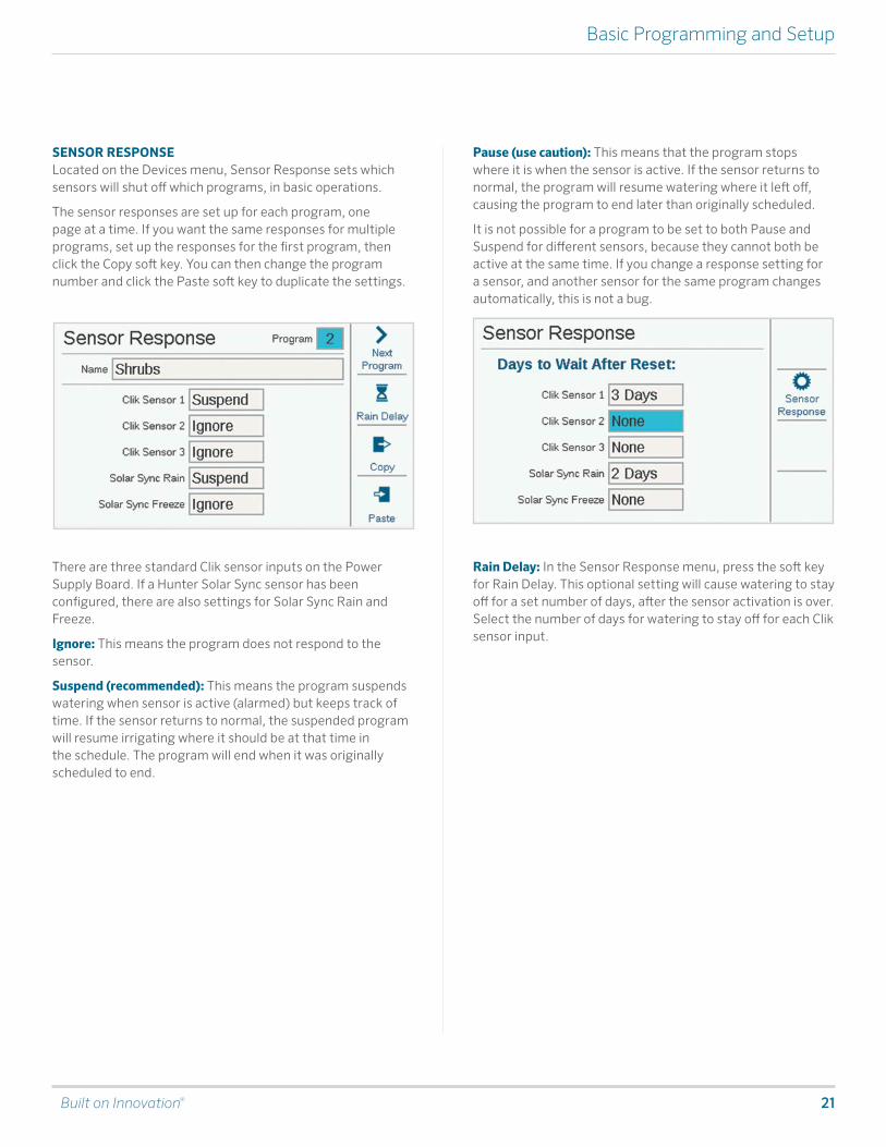
Basic Programming and Setup
SENSOR RESPONSELocated on the Devices menu, Sensor Response sets which sensors will shut off which programs, in basic operations.
The sensor responses are set up for each program, one page at a time. If you want the same responses for multiple programs, set up the responses for the first program, then click the Copy soft key. You can then change the program number and click the Paste soft key to duplicate the settings.
There are three standard Clik sensor inputs on the Power Supply Board. If a Hunter Solar Sync sensor has been configured, there are also settings for Solar Sync Rain and Freeze.
Ignore: This means the program does not respond to the sensor.
Suspend (recommended): This means the program suspends watering when sensor is active (alarmed) but keeps track of time. If the sensor returns to normal, the suspended program will resume irrigating where it should be at that time in the schedule. The program will end when it was originally scheduled to end.
Pause (use caution): This means that the program stops where it is when the sensor is active. If the sensor returns to normal, the program will resume watering where it left off, causing the program to end later than originally scheduled.
It is not possible for a program to be set to both Pause and Suspend for different sensors, because they cannot both be active at the same time. If you change a response setting for a sensor, and another sensor for the same program changes automatically, this is not a bug.
Rain Delay: In the Sensor Response menu, press the soft key for Rain Delay. This optional setting will cause watering to stay off for a set number of days, after the sensor activation is over. Select the number of days for watering to stay off for each Clik sensor input.

22 hunter.direct/ACC2help
Basic Programming and Setup
SOLAR SYNC®After connecting a Solar Sync sensor to the controller, set up operation in the Devices, Solar Sync menu.
• Check the box to Enable Solar Sync.• Choose the Region and set the Water Adjustment,
according to the Solar Sync manual instructions.• For normal operations, this is all that is necessary. It will
take the Solar Sync two or three days to register enough climate data to begin adjusting.
Solar Sync Delay allows a number of days to wait before automatic Solar Sync adjustment goes into effect (to establish new landscape, for example). Enter a number of days (1–250) to wait, and specify the Adjustment During Delay percentage to use during the delay period. At the end of the delay, the Solar Sync will begin adjusting automatically for the current climate conditions.
The delay does not interfere with the Solar Sync Rain and Temp functions. They will be operational during the delay.
Complete the setup by setting the programs to use Solar Sync in the Program, Seasonal Adjust menu.
FLOW SENSORSTo connect one or more flow sensors, set up operation in the Devices, Flow Sensors menu.
Select the sensor input number (1–6) to be set up. The controller has three Flow Sensor inputs built in, but three more can be added with the A2C-F3 Flow Expansion module.
ACC2 Decoder versions may also read flow via the two-wire path when flow sensors are connected to ICD-SEN sensor decoders. Use the Location window to select Controller (corresponding to one of the Flow terminals on the Power Supply Board or A2C-F3 flow expansion modules), or to select the decoder output module to which the flow sensor will be connected.
Specify the address of the sensor decoder for the flow sensor. Flow sensors may only be connected to Port “A” of a sensor decoder.
Check the box for either “Hunter” or “Other” flow meters.
If Hunter is checked, move to the Model field and select the Hunter FCT model number for the diameter of the pipe. This is all that is necessary to calibrate the setup.
“Wireless” is only checked for use with the Hunter WFS (wireless flow sensor), which requires a receiver installed at the controller.
If Other is checked, you must select the Flow Sensor Style and enter the calibration information. Some use K-factor and Offset, and others are Pulse type. Consult the flow meter supplier’s documentation for the correct settings or contact Hunter Technical Support for additional information.
K-Factor and Offset: Obtain these values from the flow sensor manual, and enter here.

Built on Innovation® 23
Stations Menu
Pulse type: Enter the amount equal to a single pulse.
Enter the information for each flow sensor that is connected to a flow terminal. There are copy and paste soft keys available, if all the meters are the same type and size.
Once this information is entered for each flow sensor input, the controller is ready to read flow. However, each flow sensor must be attached to a Flow Zone (Flow, Flow Zones) before real time monitoring can occur.
Flow Totals may be viewed at the Flow menu.
Current flow rates (by sensor) can be read from the Home/Activity screen with the View Flow soft key.
Flow Monitoring: Additional setup for station level flow monitoring is required in the Flow menu (Flow Zones), and in the Stations, Station Setup menu.
Stations Menu
Most of the items in Stations are covered in more detail in other sections.
STATION SETUP
Allows stations to be named. Most other functions are described in more detail in the Flow Operations section.
Station P/MV Usage indicates which normally closed P/MV outputs the station will activate, whenever it runs.
Station Flow Zone assignment (required for Flow Manager and/or Flow Monitoring).
Flow Priority (used in Flow Manager): Check the box to make a station is more likely to water earlier in flow management.
Flow Rate: Enter or learn the typical flow for the station. Used in both Flow Manager and Flow Monitor.
Delay: Sets the amount of time the station can run before high or low flows will cause an alarm. Set longer delays for stations that take longer to stabilize flow.
P/MV boxes with the “X” are unavailable, because they are already assigned to other Flow Zones or MainSafe™ zones.
24 hunter.direct/ACC2help
Stations Menu
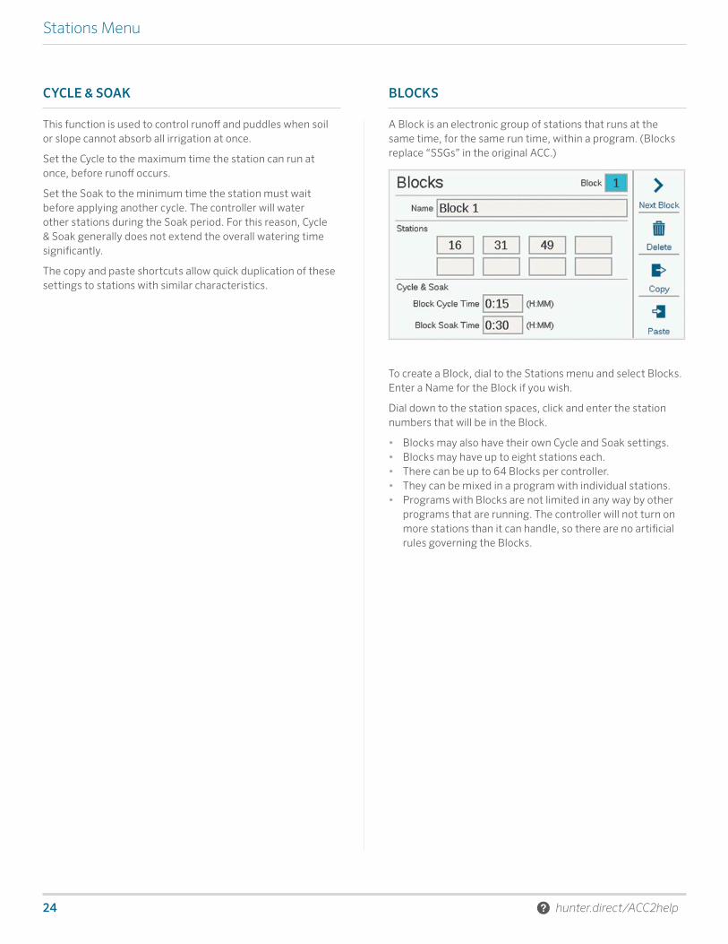
CYCLE & SOAK
This function is used to control runoff and puddles when soil or slope cannot absorb all irrigation at once.
Set the Cycle to the maximum time the station can run at once, before runoff occurs.
Set the Soak to the minimum time the station must wait before applying another cycle. The controller will water other stations during the Soak period. For this reason, Cycle & Soak generally does not extend the overall watering time significantly.
The copy and paste shortcuts allow quick duplication of these settings to stations with similar characteristics.
BLOCKS
A Block is an electronic group of stations that runs at the same time, for the same run time, within a program. (Blocks replace “SSGs” in the original ACC.)
To create a Block, dial to the Stations menu and select Blocks. Enter a Name for the Block if you wish.
Dial down to the station spaces, click and enter the station numbers that will be in the Block.
• Blocks may also have their own Cycle and Soak settings.• Blocks may have up to eight stations each.• There can be up to 64 Blocks per controller.• They can be mixed in a program with individual stations.• Programs with Blocks are not limited in any way by other
programs that are running. The controller will not turn on more stations than it can handle, so there are no artificial rules governing the Blocks.

Built on Innovation® 25
Stations Menu
STATION LIMITS
Station Limits set how many stations can run at once, at various levels.
Stack or Overlap means that each program can be manually set to Overlap with other programs, or be required to stack. Programs that are set to stack can only run by themselves.
SmartStack specifies a maximum number of programs that are allowed to overlap across the whole controller.
Maximum Simultaneous Stations is the total number of simultaneous stations that can occur for any reason in the entire controller. This is mainly for use with the Flow Manager, but applies to all situations.
If Flow Manager is enabled, the display will also show Program Limits. This sets the max number of stations that can run within any one program. This might be used to force irrigation to be spread over a larger number of programs, when Flow Manager is scheduling stations on to reach a flow rate target.
ACC2 Decoder can operate up to 30 simultaneous stations per controller, but only 20 per decoder output module.
STATION SUMMARY
The Station Summary is a report available for each station showing exactly how it is going to run, based on the current setup and programming. It is a report only, and does not allow changes to be made directly from this screen.

26 hunter.direct/ACC2help
Devices Menu
Devices Menu
Devices allows setup of common external devices that the controller can use. The functions in the Devices menu are covered in more detail in other sections.
P/MV OPERATION
Set the Location for the P/MV (terminals on the controller power supply board, or the decoder output module if using decoder control).
Set the Style, Normally Closed or Normally Open, for the Pump/Master Valve outputs.
Change Location, if the P/MV is assigned to a decoder instead of a controller terminal.
Pumps should always be set to Normally Closed to prevent damage.
The P/MV Delay sets how long the P/MV will remain active if a station pauses, such as during the delay between stations.
FLOW SENSORS
Flow Sensor setup is covered in detail in the Basic Programming, Sensors, Flow Sensors section.
SOLAR SYNC®
Solar Sync setup is covered in detail in the Basic Programming, Sensors, Solar Sync section.
CLIK SENSORS
Clik sensor setup is covered in detail in the Basic Programming, Sensors, Clik Sensors section. Hunter sensors are normally-closed, and open when an alarm is active. The sensor inputs can be changed to normally-open (close on alarm) when used with other devices.
SENSOR RESPONSE
Sensor Response is covered in detail in the Basic Programming, Sensors, Flow Sensors section.
A sensor response setting is required for any sensor to be able to shut off any program in the controller.
Built on Innovation® 27
Flow Menu
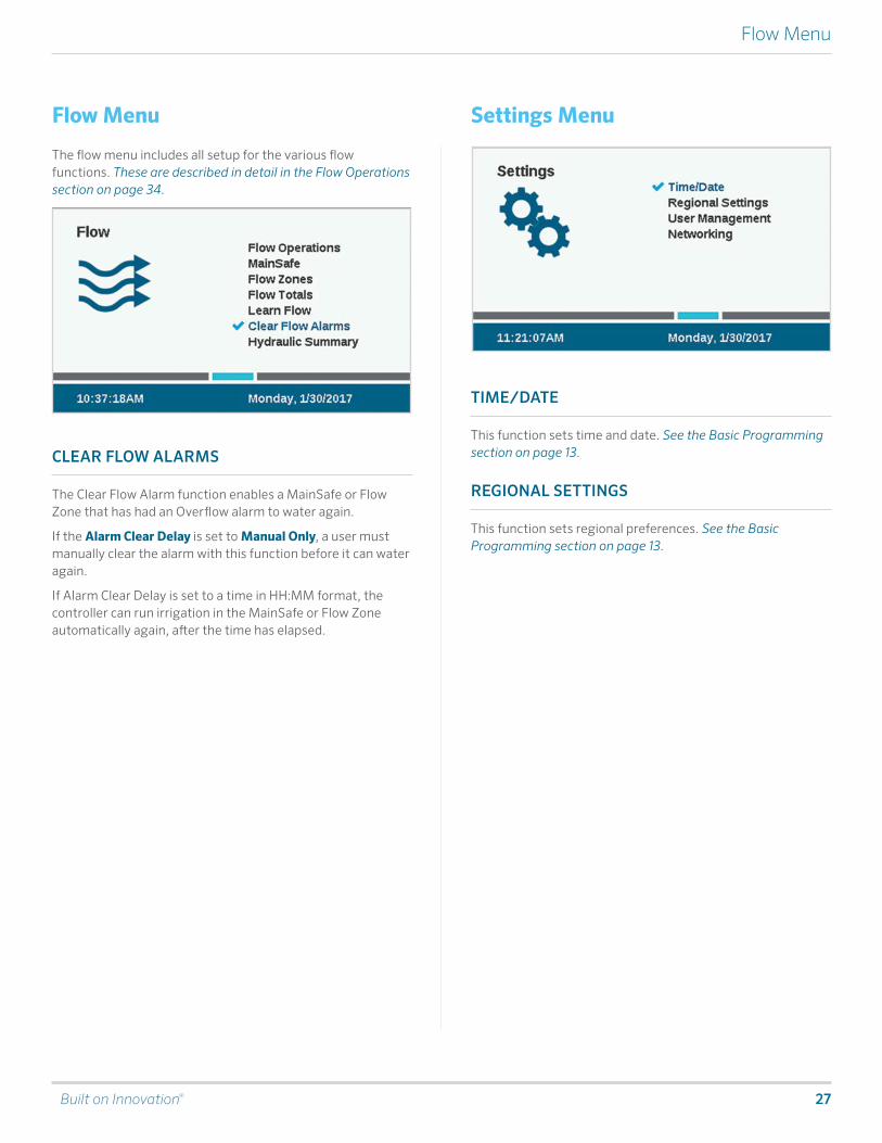
Flow Menu
The flow menu includes all setup for the various flow functions. These are described in detail in the Flow Operations section on page 34.
CLEAR FLOW ALARMS
The Clear Flow Alarm function enables a MainSafe or Flow Zone that has had an Overflow alarm to water again.
If the Alarm Clear Delay is set to Manual Only, a user must manually clear the alarm with this function before it can water again.
If Alarm Clear Delay is set to a time in HH:MM format, the controller can run irrigation in the MainSafe or Flow Zone automatically again, after the time has elapsed.
Settings Menu
TIME/DATE
This function sets time and date. See the Basic Programming section on page 13.
REGIONAL SETTINGS
This function sets regional preferences. See the Basic Programming section on page 13.

28 hunter.direct/ACC2help
Settings Menu
USER MANAGEMENT
This allows a password to be created for the controller. Users will be required to enter the correct PIN (personal identification number) before operating the controller. If a single PIN is entered at the top, it is required for all users, and provides the same level of access to all.
Check the box for Enable User Management to create one or more PINs. Once it is checked, only an Admin-level user who is successfully logged in can uncheck this box.
It is also possible to define different users, and individual PINs.
If passwords are enabled, and the password is lost or forgotten, you will be locked out of the controller.
There are two levels of authorization, Admin and Crew.
Crew-level access allows to manual operations and the ability to view programming.
Only Admins can modify programming and other settings.
User log-ins are tracked in the Controller Log.
To add a user, press the soft key for New User. You may then enter the user’s name with the keyboard that will appear when the Name field is selected. For each user, select the Type (Admin or Crew), and create a unique PIN for that person.
It is also possible for an Admin to delete users with the Delete User soft key.
Users will be automatically logged off after 30 minutes of no activity.
NETWORKING
If the internal Wi-Fi or LAN modules are installed, Networking will display the network settings of these devices.
Network Info: Displays current setup. Only Wi-Fi Direct Connect is supported at this time. The Network shown will be HunterACC-xxxx, where xxxx is a number code, and this is the device address to search for in your mobile device.
Wi-Fi Setup: The Wi-Fi Setup menu displays two check boxes, Direct Connect (for a nearby mobile device) and Network. The Network selection will show nearby networks, but network connections are not supported at this time. Direct connections from a smart mobile device will allow remote control, text entry, and flow reporting within the range of the mobile device.
Central Setup: This will show addresses and URLs for future use, but this is not supported at this time.
Built on Innovation® 29
Diagnostics Menu
Diagnostics Menu
Attention messages do not interfere with normal automatic irrigation.
All attention messages in the Home screen create logs. The first step to understanding any problem or message is to click the soft key for View Logs, or access the logs from the Diagnostics menu.
Other helpful tools are also located at Diagnostics. Decoder controllers include separate diagnostics for decoder conditions in the Decoder menu.
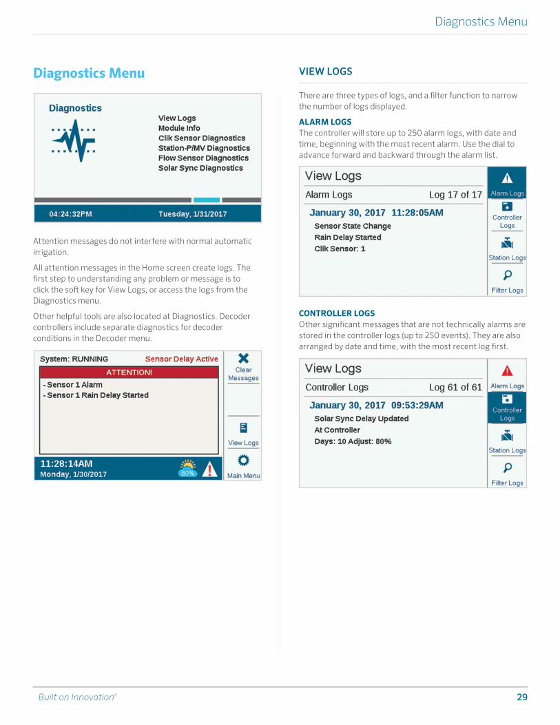
VIEW LOGS
There are three types of logs, and a filter function to narrow the number of logs displayed.
ALARM LOGSThe controller will store up to 250 alarm logs, with date and time, beginning with the most recent alarm. Use the dial to advance forward and backward through the alarm list.
CONTROLLER LOGS Other significant messages that are not technically alarms are stored in the controller logs (up to 250 events). They are also arranged by date and time, with the most recent log first.
30 hunter.direct/ACC2help
Diagnostics Menu
STATION LOGSStation logs record every event that occurs in the controller (up to 1,500 events), beginning with the most recent. This can be useful for advanced troubleshooting, or to verify that a station actually watered.
FILTER LOGSThis allows any of the three logs to be filtered by date, or by record number.
EXPORT LOGS
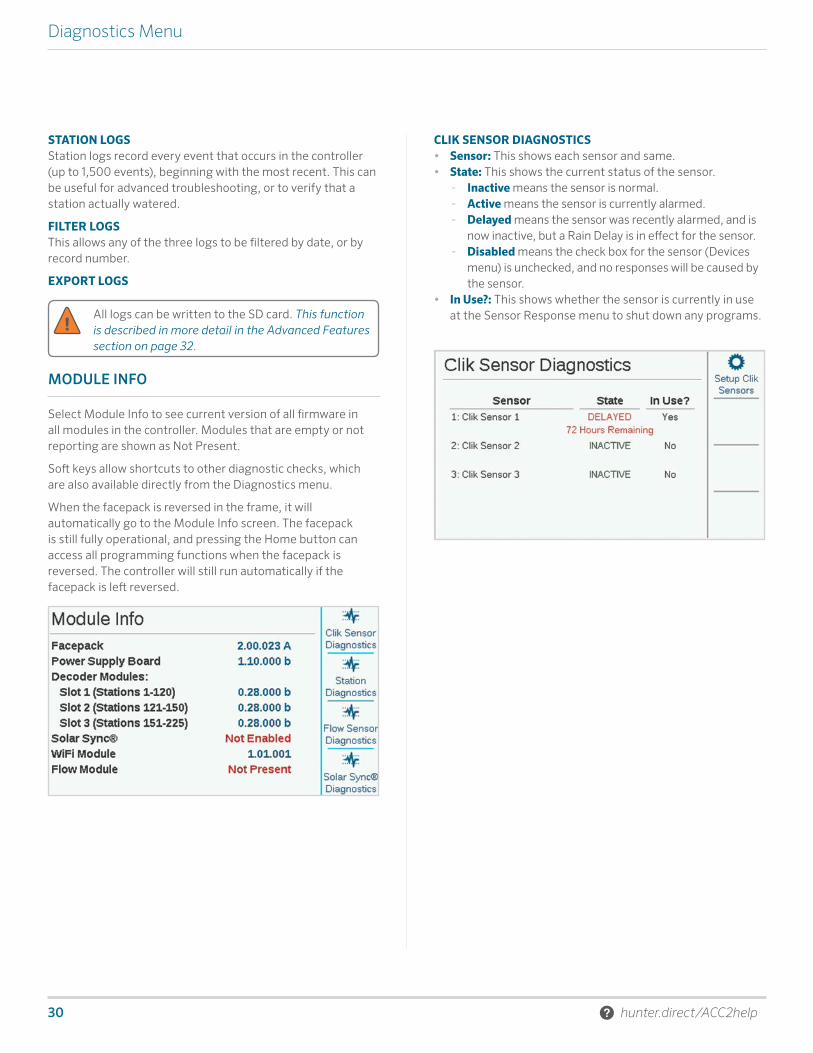
CLIK SENSOR DIAGNOSTICS• Sensor: This shows each sensor and same.• State: This shows the current status of the sensor.
- Inactive means the sensor is normal. - Active means the sensor is currently alarmed. - Delayed means the sensor was recently alarmed, and is
now inactive, but a Rain Delay is in effect for the sensor. - Disabled means the check box for the sensor (Devices
menu) is unchecked, and no responses will be caused by the sensor.
• In Use?: This shows whether the sensor is currently in use at the Sensor Response menu to shut down any programs.
MODULE INFO
Select Module Info to see current version of all firmware in all modules in the controller. Modules that are empty or not reporting are shown as Not Present.
Soft keys allow shortcuts to other diagnostic checks, which are also available directly from the Diagnostics menu.
When the facepack is reversed in the frame, it will automatically go to the Module Info screen. The facepack is still fully operational, and pressing the Home button can access all programming functions when the facepack is reversed. The controller will still run automatically if the facepack is left reversed.
All logs can be written to the SD card. This function is described in more detail in the Advanced Features section on page 32.
Built on Innovation® 31
Diagnostics Menu
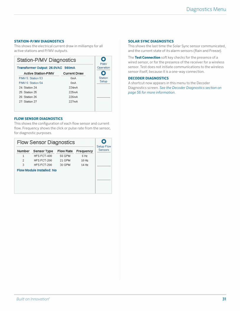
STATION-P/MV DIAGNOSTICSThis shows the electrical current draw in milliamps for all active stations and P/MV outputs.
FLOW SENSOR DIAGNOSTICSThis shows the configuration of each flow sensor and current flow. Frequency shows the click or pulse rate from the sensor, for diagnostic purposes.
SOLAR SYNC DIAGNOSTICSThis shows the last time the Solar Sync sensor communicated, and the current state of its alarm sensors (Rain and Freeze).
The Test Connection soft key checks for the presence of a wired sensor, or for the presence of the receiver for a wireless sensor. Test does not initiate communications to the wireless sensor itself, because it is a one-way connection.
DECODER DIAGNOSTICSA shortcut now appears in this menu to the Decoder Diagnostics screen. See the Decoder Diagnostics section on page 56 for more information.
32 hunter.direct/ACC2help
Advanced Features
Advanced Features
EXPORT LOGS
Logs may be exported in a simple text format to the internal SD card in the facepack if additional help is needed for troubleshooting, or just for record-keeping purposes.
Enter a unique file name by clicking in the File Name box.
Select the boxes for the types of Logs desired.
Select and click the Export Logs button to save the file to the SD card. The card may then be inserted into a computer or other device with SD card reader, and saved or sent to another location.
EASY RETRIEVE
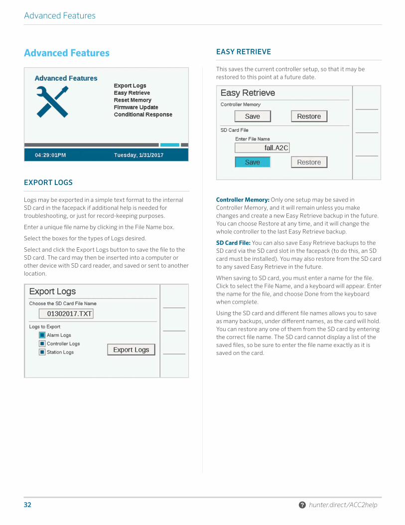
This saves the current controller setup, so that it may be restored to this point at a future date.
Controller Memory: Only one setup may be saved in Controller Memory, and it will remain unless you make changes and create a new Easy Retrieve backup in the future. You can choose Restore at any time, and it will change the whole controller to the last Easy Retrieve backup.
SD Card File: You can also save Easy Retrieve backups to the SD card via the SD card slot in the facepack (to do this, an SD card must be installed). You may also restore from the SD card to any saved Easy Retrieve in the future.
When saving to SD card, you must enter a name for the file. Click to select the File Name, and a keyboard will appear. Enter the name for the file, and choose Done from the keyboard when complete.
Using the SD card and different file names allows you to save as many backups, under different names, as the card will hold. You can restore any one of them from the SD card by entering the correct file name. The SD card cannot display a list of the saved files, so be sure to enter the file name exactly as it is saved on the card.
Built on Innovation® 33
Advanced Features
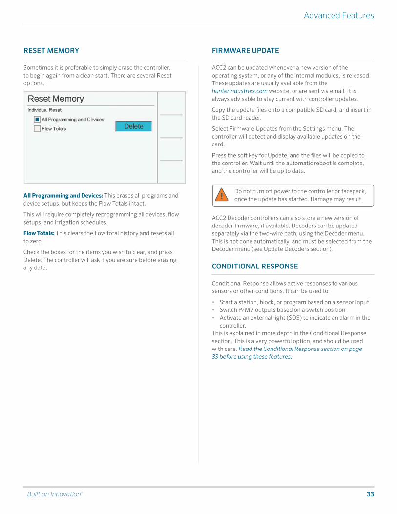
RESET MEMORY
Sometimes it is preferable to simply erase the controller, to begin again from a clean start. There are several Reset options.
All Programming and Devices: This erases all programs and device setups, but keeps the Flow Totals intact.
This will require completely reprogramming all devices, flow setups, and irrigation schedules.
Flow Totals: This clears the flow total history and resets all to zero.
Check the boxes for the items you wish to clear, and press Delete. The controller will ask if you are sure before erasing any data.
FIRMWARE UPDATE
ACC2 can be updated whenever a new version of the operating system, or any of the internal modules, is released. These updates are usually available from the hunterindustries.com website, or are sent via email. It is always advisable to stay current with controller updates.
Copy the update files onto a compatible SD card, and insert in the SD card reader.
Select Firmware Updates from the Settings menu. The controller will detect and display available updates on the card.
Press the soft key for Update, and the files will be copied to the controller. Wait until the automatic reboot is complete, and the controller will be up to date.
Do not turn off power to the controller or facepack, once the update has started. Damage may result.
ACC2 Decoder controllers can also store a new version of decoder firmware, if available. Decoders can be updated separately via the two-wire path, using the Decoder menu. This is not done automatically, and must be selected from the Decoder menu (see Update Decoders section).
CONDITIONAL RESPONSE
Conditional Response allows active responses to various sensors or other conditions. It can be used to:
• Start a station, block, or program based on a sensor input• Switch P/MV outputs based on a switch position• Activate an external light (SOS) to indicate an alarm in the
controller.This is explained in more depth in the Conditional Response section. This is a very powerful option, and should be used with care. Read the Conditional Response section on page 33 before using these features.
34 hunter.direct/ACC2help
Flow Operations
Flow Operations
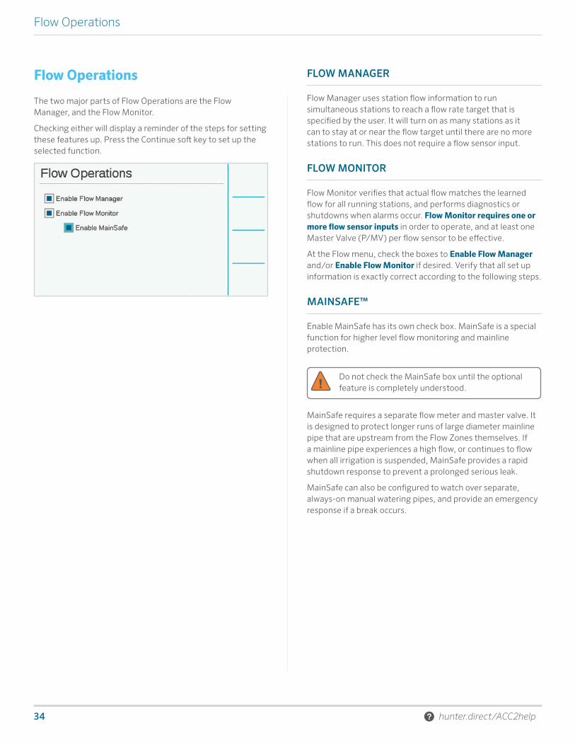
The two major parts of Flow Operations are the Flow Manager, and the Flow Monitor.
Checking either will display a reminder of the steps for setting these features up. Press the Continue soft key to set up the selected function.
FLOW MANAGER
Flow Manager uses station flow information to run simultaneous stations to reach a flow rate target that is specified by the user. It will turn on as many stations as it can to stay at or near the flow target until there are no more stations to run. This does not require a flow sensor input.
FLOW MONITOR
Flow Monitor verifies that actual flow matches the learned flow for all running stations, and performs diagnostics or shutdowns when alarms occur. Flow Monitor requires one or more flow sensor inputs in order to operate, and at least one Master Valve (P/MV) per flow sensor to be effective.
At the Flow menu, check the boxes to Enable Flow Manager and/or Enable Flow Monitor if desired. Verify that all set up information is exactly correct according to the following steps.
MAINSAFE™
Enable MainSafe has its own check box. MainSafe is a special function for higher level flow monitoring and mainline protection.
Do not check the MainSafe box until the optional feature is completely understood.
MainSafe requires a separate flow meter and master valve. It is designed to protect longer runs of large diameter mainline pipe that are upstream from the Flow Zones themselves. If a mainline pipe experiences a high flow, or continues to flow when all irrigation is suspended, MainSafe provides a rapid shutdown response to prevent a prolonged serious leak.
MainSafe can also be configured to watch over separate, always-on manual watering pipes, and provide an emergency response if a break occurs.

Built on Innovation® 35
Flow Operations
SET UP FLOW MONITOR
The Flow Monitor requires the following information to operate correctly:
• Install and set up a flow sensor (Devices menu).• Install and set up a P/MV (Devices menu).• Set up a Flow Zone, and complete all information for the
Flow Zone (Flow menu). • Attach each station to a Flow Zone (Station Setup menu).• Learn Flow for all stations with run times (Flow menu).
FLOW ZONESA Flow Zone defines a section of pipe and a group of stations attached to that pipe, which is managed as a hydraulic unit. Flow Zones are used for both Flow Manager and Flow Monitor.
Each Flow Zone has a check box for “Manage Flow” and “Monitor Flow.” To monitor flow, check that box. Then complete the settings and rules for the Flow Zone.
Overflow/Underflow Alarm Limits: ACC2 sets the over- and underflow limits for each station’s learned flow at the flow zone level. Enter the maximum and minimum flow percentages you want the Flow Zone to allow for the stations attached to the Flow Zone. If these limits are set too close to 100%, there is a greater chance of false alarms, due to natural fluctuations in the flow.
FLOW MAPIn the Flow Zones menu, press the soft key for Flow Map. This tells the controller how the Flow Zone is connected, and which devices are used in that hydraulic unit. All stations must be downstream from the flow sensors and master valves that are checked here.
Flow Sensor Assignment: Check the box for the Flow Sensor or sensors connected to the Flow Zone.
If an X is in one of the Flow Sensor boxes, the sensor has already been assigned to another Flow Zone, and is not available for this Flow Zone.
If a Flow Sensor number does not appear, it has already been assigned to a MainSafe, and is not available for Flow Zone monitoring.
P/MV Assignment: Check the box for the Master Valve that is installed in line with the flow sensor on this flow zone.
If an X is in one of the P/MV boxes, it has already been assigned to another Flow Zone, and is not available for this Flow Zone.
If a P/MV number does not appear, it has already been assigned to a MainSafe, and is not available for Flow Zone monitoring.
MainSafe™ Assignment: If using this optional feature, select the MainSafe zone that is upstream from the Flow Zone. If MainSafes are not being used, leave this set to “None.”
The Flow Sensor and P/MV assignments for the selected MainSafe zone are shown to the right.

36 hunter.direct/ACC2help
Flow Operations
FLOW LIMITSIn the Flow Zones menu, press the soft key for Flow Limits.
Maximum Flow: This sets the highest possible flow rate allowed in the Flow Zone for any reason. This should be considerably larger than the maximum flow allowed in normal irrigation (so that it does not alarm before station-level diagnostics can be performed). When the flow sensor detects a flow higher than this, the irrigation will be shut down.
Unscheduled Flow: This is the maximum amount of flow allowed when no stations are actively running. This is only to allow manual watering by hand when the controller is not watering automatically. When the rate is exceeded, the controller will alarm.
If Unscheduled Flow is set to OFF, the controller will not respond to unscheduled flow.
Flow Alarm Delays: This sets an amount of time before the Max or Unscheduled flow rates will cause an alarm, and sets how long the Flow Zone will be shut down.
Alarm Delay: High flows will alarm immediately if this is set to None, or they will be ignored until they have lasted as long as the time entered here. Set in M:SS format; the longest delay is 9 minutes, 59 seconds. This can eliminate false alarms from temporary surges in flow.
This delay should be longer than the delays for the stations attached to the Flow Zone.
Alarm Clear Delay: This sets the amount of time a Flow Zone will remain shut down before allowing new automatic irrigation attempts. Set in HH:MM format, the longest delay setting is 23 hours, 59 minutes.
If Alarm Clear Delay is set to Manual Only, automatic irrigation will never resume after a high flow or unscheduled flow alarm, until it is manually cleared by an operator at the controller. The operator must dial to the Flow menu, select Clear Flow Alarms, the Flow Alarms that should be cleared, and click Clear Selected.
FLOW ALLOWANCESIn the Flow Zones menu, press the soft key for Allowances.
Watering Budget: Enter the total amount of flow that can be allowed in this Flow Zone in the calendar month. If the total flow exceeds the monthly budget, an alarm message will appear on the screen. The controller will not automatically stop watering when this alarm occurs.
Manual Watering Allowance: This sets an additional flow rate amount allowed for manual irrigation. This is added to all other limits in the controller and prevents alarms from occurring until the expected flow — plus the amount entered here — is exceeded.
Built on Innovation® 37
Flow Operations
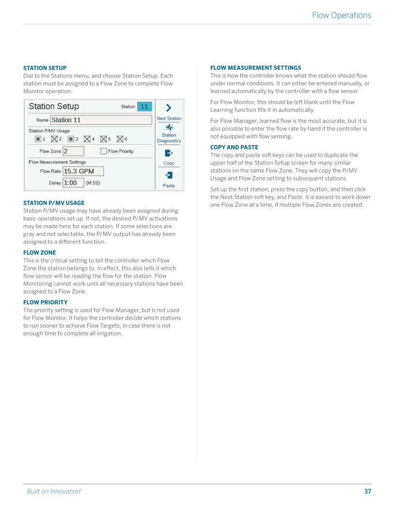
STATION SETUPDial to the Stations menu, and choose Station Setup. Each station must be assigned to a Flow Zone to complete Flow Monitor operation.
STATION P/MV USAGEStation P/MV usage may have already been assigned during basic operations set up. If not, the desired P/MV activations may be made here for each station. If some selections are gray and not selectable, the P/MV output has already been assigned to a different function.
FLOW ZONEThis is the critical setting to tell the controller which Flow Zone the station belongs to. In effect, this also tells it which flow sensor will be reading the flow for the station. Flow Monitoring cannot work until all necessary stations have been assigned to a Flow Zone.
FLOW PRIORITYThe priority setting is used for Flow Manager, but is not used for Flow Monitor. It helps the controller decide which stations to run sooner to achieve Flow Targets, in case there is not enough time to complete all irrigation.
FLOW MEASUREMENT SETTINGSThis is how the controller knows what the station should flow under normal conditions. It can either be entered manually, or learned automatically by the controller with a flow sensor.
For Flow Monitor, this should be left blank until the Flow Learning function fills it in automatically.
For Flow Manager, learned flow is the most accurate, but it is also possible to enter the flow rate by hand if the controller is not equipped with flow sensing.
COPY AND PASTEThe copy and paste soft keys can be used to duplicate the upper half of the Station Setup screen for many similar stations on the same Flow Zone. They will copy the P/MV Usage and Flow Zone setting to subsequent stations.
Set up the first station, press the copy button, and then click the Next Station soft key, and Paste. It is easiest to work down one Flow Zone at a time, if multiple Flow Zones are created.

38 hunter.direct/ACC2help
Flow Operations
LEARN FLOWThe final step in Flow Monitor setup (unless the MainSafe option is enabled) is the actual learning process.
Dial to the Flow menu, and select Learn Flow. The screen will show the status of the last learn flow attempt, if there was one.
Flow learning will only test stations that already have a Run Time in a program.
Flow learning will cancel all other irrigation, automatic and manual, until the learning is complete. Flow cannot be learned while other stations are running for other reasons.
Press the soft key for Report to verify that stations are ready to learn. This will show how many flow sensors are configured, how many stations have run times, and how many already have flow rate data.
If all stations have run times, press the Learn soft key. The controller will begin starting stations, one at a time, for up to five minutes each, plus the delay time set for the station) to learn the flow. If flow stabilizes sooner, the controller will move to the next station without running the full five minutes.
Flow learning can be a lengthy process, depending on how many stations there are, and how stable the flow is.
When the learning is complete, the Learn Flow screen will summarize how many stations were learned, and how many have failed. Troubleshoot the failed stations (either in setup, or in the field) and try learning again to fill in the failed stations.
SCHEDULE FLOW LEARNINGIt is possible to set the controller to Learn Flow automatically at a later time and date. Remember that flow learning will cancel any other automatic irrigation, so choose a time and date that are not conflicting with critical irrigation.
Built on Innovation® 39
Flow Operations
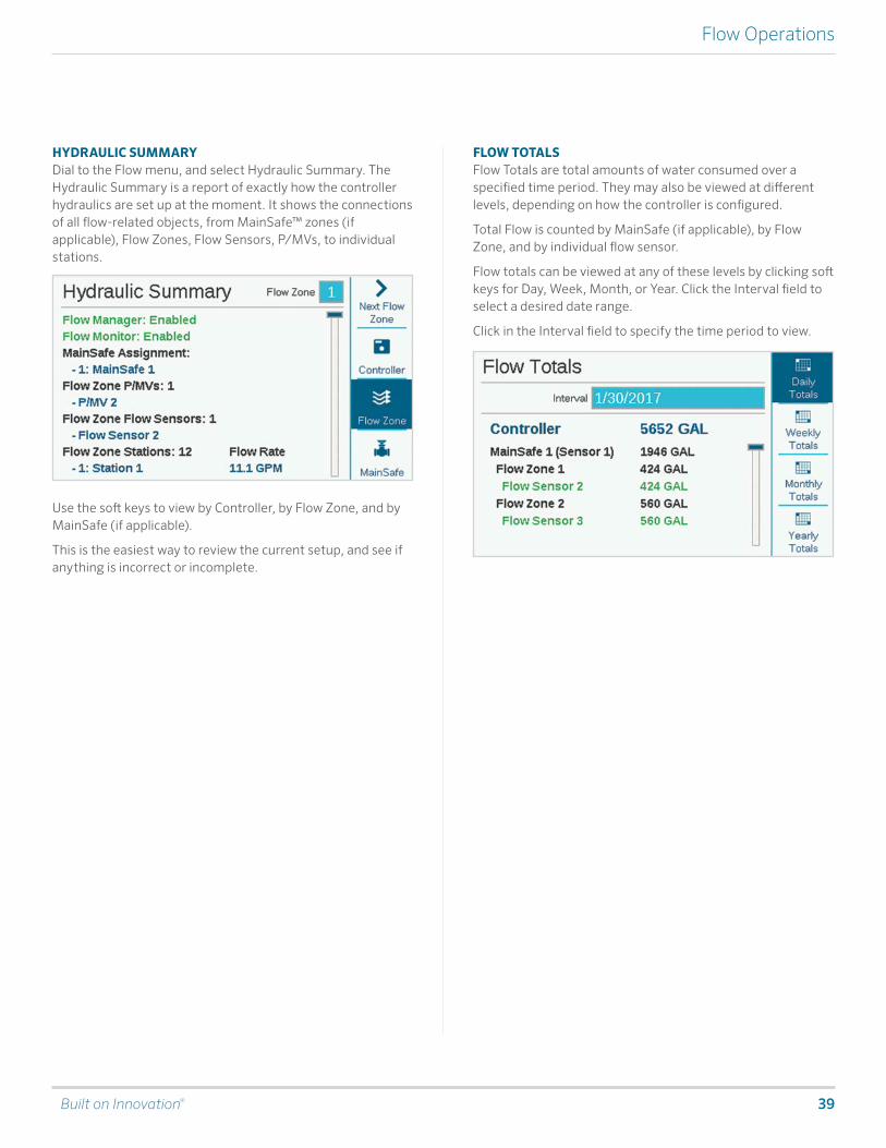
HYDRAULIC SUMMARYDial to the Flow menu, and select Hydraulic Summary. The Hydraulic Summary is a report of exactly how the controller hydraulics are set up at the moment. It shows the connections of all flow-related objects, from MainSafe™ zones (if applicable), Flow Zones, Flow Sensors, P/MVs, to individual stations.
Use the soft keys to view by Controller, by Flow Zone, and by MainSafe (if applicable).
This is the easiest way to review the current setup, and see if anything is incorrect or incomplete.
FLOW TOTALS Flow Totals are total amounts of water consumed over a specified time period. They may also be viewed at different levels, depending on how the controller is configured.
Total Flow is counted by MainSafe (if applicable), by Flow Zone, and by individual flow sensor.
Flow totals can be viewed at any of these levels by clicking soft keys for Day, Week, Month, or Year. Click the Interval field to select a desired date range.
Click in the Interval field to specify the time period to view.
40 hunter.direct/ACC2help
Flow Operations
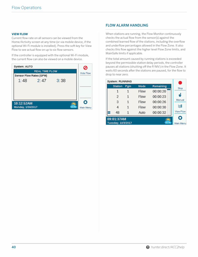
VIEW FLOWCurrent flow rate on all sensors can be viewed from the Home/Activity screen at any time (or via mobile device, if the optional Wi-Fi module is installed). Press the soft key for View Flow to see actual flow on up to six flow sensors.
If the controller is equipped with the optional Wi-Fi module, the current flow can also be viewed on a mobile device.
FLOW ALARM HANDLING
When stations are running, the Flow Monitor continuously checks the actual flow from the sensor(s) against the combined learned flow of the stations, including the overflow and underflow percentages allowed in the Flow Zone. It also checks this flow against the higher level Flow Zone limits, and MainSafe limits if applicable.
If the total amount caused by running stations is exceeded beyond the permissible station delay periods, the controller pauses all stations (shutting off the P/MV) in the Flow Zone. It waits 60 seconds after the stations are paused, for the flow to drop to near zero.

Built on Innovation® 41
Flow Operations
STATION-LEVEL ALARMSIf flow does drop to near zero when the Flow Zone is paused, the controller then begins running the stations that were running at the time of the alarm, one by one, to test which station(s) are causing the high flow conditions. The controller will mark failed stations in the logs, and continue irrigating with stations that pass the individual flow tests.
FLOW ZONE OR MAINSAFE™ ALARMSIf flow does not drop substantially during the diagnostic pause period, the controller determines there is a Mainline Overflow, and will not resume irrigating or perform further diagnostics. It will remain shut down for the period specified in the Alarm Clear Delay setting on the Flow Zones screen.
When flow alarms are detected at the Flow Zone or MainSafe level, they can be cleared from the Flow menu, Clear Flow Alarms. There also will be a shortcut soft key available to Clear Flow Alarms when these conditions are detected, after View Messages has been selected.
If the actual flow exceeds the Maximum Flow allowance for the Flow Zone, and continues for the time set in the Alarm Delay, the Flow Zone alarms and shuts down without further diagnostics. The same applies to MainSafe zones, if applicable. The controller assumes the overflow condition is the result of a mainline failure, above the station level.
If flow exceeds any Unscheduled Flow allowance when no stations are supposed to be running, and continues for the time set in the Alarm Delay, the Flow Zone and/or MainSafe zone will also be shut down.
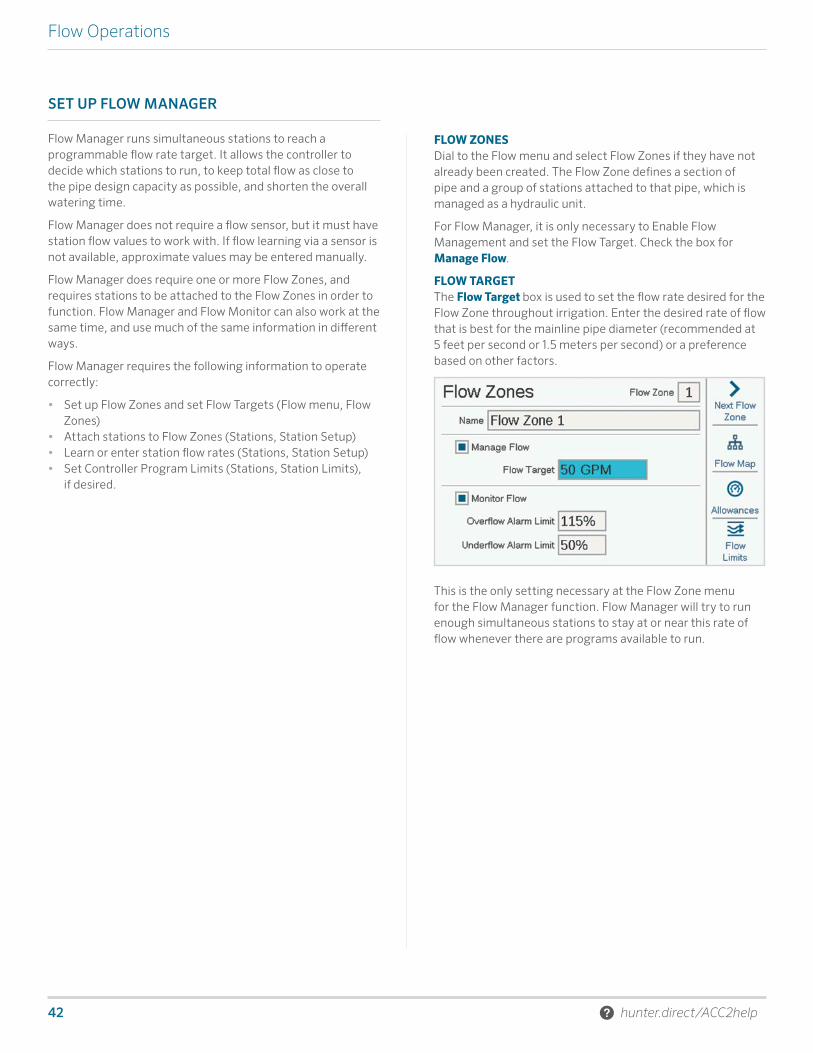
42 hunter.direct/ACC2help
Flow Operations
SET UP FLOW MANAGER
Flow Manager runs simultaneous stations to reach a programmable flow rate target. It allows the controller to decide which stations to run, to keep total flow as close to the pipe design capacity as possible, and shorten the overall watering time.
Flow Manager does not require a flow sensor, but it must have station flow values to work with. If flow learning via a sensor is not available, approximate values may be entered manually.
Flow Manager does require one or more Flow Zones, and requires stations to be attached to the Flow Zones in order to function. Flow Manager and Flow Monitor can also work at the same time, and use much of the same information in different ways.
Flow Manager requires the following information to operate correctly:
• Set up Flow Zones and set Flow Targets (Flow menu, Flow Zones)
• Attach stations to Flow Zones (Stations, Station Setup)• Learn or enter station flow rates (Stations, Station Setup)• Set Controller Program Limits (Stations, Station Limits),
if desired.
FLOW ZONESDial to the Flow menu and select Flow Zones if they have not already been created. The Flow Zone defines a section of pipe and a group of stations attached to that pipe, which is managed as a hydraulic unit.
For Flow Manager, it is only necessary to Enable Flow Management and set the Flow Target. Check the box for Manage Flow.
FLOW TARGETThe Flow Target box is used to set the flow rate desired for the Flow Zone throughout irrigation. Enter the desired rate of flow that is best for the mainline pipe diameter (recommended at 5 feet per second or 1.5 meters per second) or a preference based on other factors.
This is the only setting necessary at the Flow Zone menu for the Flow Manager function. Flow Manager will try to run enough simultaneous stations to stay at or near this rate of flow whenever there are programs available to run.

Built on Innovation® 43
Flow Operations
STATION SETUPFlow Manager requires:
• The station’s Flow Zone assignment• The Flow priority (checked or not checked)• The station Flow Rate
FLOW ZONEThis tells the controller the Flow Zone to which the station belongs.
If there are multiple Flow Zones (collections of stations attached to the same mainline), it is possible to have a different Flow Target in each one.
It is also possible to have Flow Zones that run without Flow Manager, simultaneously with Flow Zones that are being managed.
FLOW PRIORITYThe priority setting helps the controller decide which stations to run sooner to achieve Flow Targets. Stations with the Priority box checked will be considered first, so that less critical stations can occur later in the irrigation.
FLOW RATEIf the system is equipped with a flow sensor, it is best to use the “Learn Flow” function to let the controller fill these values in.
If the system does not have a flow sensor, look up or calculate reasonable flow values for each station, and enter manually for each station.
Note that Copy and Paste do not work with flow rates. They only copy the upper half of the screen, including P/MV and Flow Zone assignments.

44 hunter.direct/ACC2help
Flow Operations
STATION LIMITSDial to Stations, Station Limits to review or change the number of stations that are allowed to run at once.
It is not necessary to change Station Limits for Flow Manager to operate, but it is possible. These settings can be used to customize the results of flow management.
Maximum Simultaneous Stations sets a hard limit on the number of stations the controller can run at once, regardless of Flow Manager or other settings. The ACC2 Decoder controller can run approximately 20 Hunter solenoids at once on a single output module, including P/MV outputs. The decoder controller can run up to 30 stations at once, provided they are spread over multiple decoder output modules, with not more than 20 active on each output module.
This may vary according to other factors, and there may be other reasons to limit the total number of simultaneous stations.
Enter a Controller number that meets your needs if the default of eight is not desirable.
If Flow Manager is enabled, a maximum number of simultaneous stations per program can also be entered. This can be useful to force the controller to spread irrigation across multiple programs, for example.
Example: Program 1 runs turf zones, and Program 2 runs shrub zones. If they are both part of the same flow-managed Flow Zone, and you know the Flow Zone can run about six zones at once, you could set a limit of three on Program 1 and three on Program 2. The controller will still flow manage to your target flow, but could only run three in either program to get there.
If the Flow Target rates are well below the rates that the Controller and Program station limits would allow, the station limits will never be reached. The controller will decide which stations to run, and in what order.
MAINSAFE™
A MainSafe is an optional level of flow monitoring and protection above the Flow Zone level. It is especially useful when:
• More than one Flow Zone has been configured from the same water supply
• When there is a long distance between the point of connection and the beginning of the actual Flow Zone(s)
• When separate mainlines are in a constantly charged state for the sole purpose of manual watering
MainSafe zones generally require their own flow sensor, and their own Master Valve. Often these are Normally Open Master Valves, which only close in the event of an alarm.
To set up a MainSafe, dial to the Flow menu, and select MainSafes.
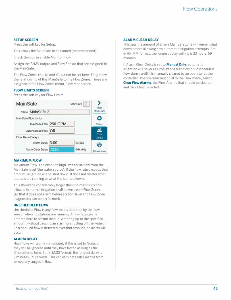
Built on Innovation® 45
Flow Operations
SETUP SCREENPress the soft key for Setup.
This allows the MainSafe to be named (recommended).
Check the box to enable Monitor Flow.
Assign the P/MV output and Flow Sensor that are assigned to the MainSafe.
The Flow Zones checks and X’s cannot be set here. They show the relationship of this MainSafe to the Flow Zones. These are assigned in the Flow Zones menu, Flow Map screen.
FLOW LIMITS SCREENPress the soft key for Flow Limits.
MAXIMUM FLOWMaximum Flow is an absolute high limit for all flow from the MainSafe level (the water source). If the flow rate exceeds that amount, irrigation will be shut down. It does not matter what stations are running or what the learned flow is.
This should be considerably larger than the maximum flow allowed in normal irrigation in all downstream Flow Zones (so that it does not alarm before station-level and Flow Zone diagnostics can be performed).
UNSCHEDULED FLOWUnscheduled Flow is any flow that is detected by the flow sensor when no stations are running. A flow rate can be entered here to permit manual watering up to the specified amount, without causing an alarm or shutting off the water. If unscheduled flow is detected over that amount, an alarm will occur.
ALARM DELAYHigh flows will alarm immediately if this is set to None, or they will be ignored until they have lasted as long as the time entered here. Set in M:SS format; the longest delay is 9 minutes, 59 seconds. This can eliminate false alarms from temporary surges in flow.
ALARM CLEAR DELAYThis sets the amount of time a MainSafe zone will remain shut down before allowing new automatic irrigation attempts. Set in HH:MM format, the longest delay setting is 23 hours, 59 minutes.
If Alarm Clear Delay is set to Manual Only, automatic irrigation will never resume after a high flow or unscheduled flow alarm, until it is manually cleared by an operator at the controller. The operator must dial to the Flow menu, select Clear Flow Alarms, the Flow Alarms that should be cleared, and click Clear Selected.

46 hunter.direct/ACC2help
Flow Operations
ALARM CLEAR DELAY (CONTINUED)This specifies how long the MainSafe zone will remain shut down after a Max Flow or Unscheduled Flow alarm occurs, in hours:minutes. This is set to 23 hours, 59 minutes, but this can be changed to other intervals, or set to Manual Only.
If Alarm Clear Delay is set to Manual Only, the controller will not water again until someone visits the site, and manually clears the flow alarm. This assumes a mainline break has occurred and that no watering should occur until it is repaired.
ALLOWANCES SCREEN
MONTHLY BUDGETEnter the total amount of flow that can be allowed in this MainSafe™ in the calendar month. If the total flow exceeds the monthly budget, an alarm message will appear on the screen. The controller will not automatically stop watering when this alarm occurs.
MANUAL WATERING ALLOWANCEThis is an additional amount of flow that is permitted over all other flow rate limits for manual watering that may occur during automatic irrigation. An alarm will not occur until other limits, plus the amount entered here, have been exceeded.
Built on Innovation® 47
Conditional Response
Conditional Response
Conditional Responses allow a sensor or condition to trigger something to happen. This can be as simple as telling a station to start when a sensor is opened, to much more complex operations such as switching water supplies to a Flow Zone based on a sensor position.
Conditional Responses are written in the form of a statement, which reads “if this happens, then do that.”
The controller may have up to 35 Conditional Response statements. Some responses may require more than one statement to achieve certain results (such as switching P/MVs).

48 hunter.direct/ACC2help
Conditional Response
SET UP A CONDITIONAL RESPONSE
Dial to Advanced Settings and select Conditional Response. Each Response has a soft key for an “If” condition, a “Then” condition (or action), and a “Review Statement” to verify that the complete response will meet the goal.
Clik Sensors can use alarms as a trigger. They can also trigger based strictly on their position, Closed or Open, without causing an alarm.
Examples: A Clik could start a program, station, etc., whenever it alarms, or a Clik input could switch between two Master Valves based upon whether it was open or closed.
Flow Zones and MainSafe zones can use Max Flow rate or Unscheduled Flow as triggers. Flow Zone triggers can be used to start an external alarm indicator, or to close a P/MV.
“Any Alarm,” or just a list of “Critical Alarms,” can be used as triggers, usually to start an external alarm indicator (see SOS).
You must review the statement and then enable it with the Enable checkbox, for the response to be in effect.
You must Review and Enable the statement (check box) before the Conditional Response statement is active.
The possible responses depend on the object (Type) chosen in the “If” statement.
• An “If” statement is for a certain type of condition to function as a trigger.
• A “Then” statement is for the action taken as a response to the trigger.

Built on Innovation® 49
Conditional Response
CONDITIONAL RESPONSE TYPESThe following table shows Conditional Response options for various situations.
“If” Type Selection Condition (Trigger) “Then” Actions Other Rules
Clik SensorsClik 1 Clik 2 Clik 3
Alarm Open Close
Start Station Start Block Start Program Close P/MV Start SOS
Manual/Auto Stop if Clears Yes/No
Solar Sync®Solar Sync Rain Solar Sync Freeze
Alarm
Flow Zone Flow Zone 1–6Max Flow Unscheduled Flow Mainline Overflow
Start SOS
Water Source Water Source 1–6Max Flow Unscheduled Flow
Start SOS
Any Alarm (All Alarms)Alarm
Close P/MV Start SOSCritical Alarm (Serious Alarms)

50 hunter.direct/ACC2help
Conditional Response
SOS (STATUS OUTPUT STATION)An SOS is a dedicated station output that is only used with Conditional Response. The purpose of the SOS is to trigger an external light or other device when the controller is in an alarmed state, so that field personnel can be notified of an alarm without having to open the controller door.
An SOS requires a dedicated station number to operate (any station number may be used). The station will turn on whenever the Conditional Response condition is in effect.
The station output may be used to directly power a 24VAC signal lamp installed in a conduit hole, or used to activate a relay for other purposes.
SET UP AN SOS STATIONIn the Conditional Response screen, use the “Then” soft key to select a “Start SOS Output” Type.
At Selection, select the unused station you want to designate as the SOS station.
• This station must not be included in any irrigation programs.
• Only one SOS station should be used per controller. • All other SOS responses should be selected to the same
SOS station number.• The SOS station output will be wired directly to the
external light or other 24V powered device.• In Decoder Controllers, the SOS must be operated by a
decoder station. We recommend programming and placing a single station ICD-100 in the controller cabinet for this purpose.
START STATIONS, PROGRAMS, AND BLOCKSWhen using Conditional Response to start a Station, Program, or Block, other options appear below the selection.
MODEIf the Mode is set to Manual, the Station, Program, or Block will run alone, and all other automatic irrigation is stopped until the response is finished.
If the Mode is set to Auto, the response will occur without halting other scheduled irrigation. If the system is using Flow Manager, the response may not begin immediately. The responding stations will be fit into the Flow Target, as available, by the Flow Manager.
If Stop if Condition Clears is checked, the Station, Block, or Program will only run while the trigger condition is present. If the condition continues, a Station or Block will run for the specified run time, and a program will run once for the duration of the program.
If the box is not checked, the response will continue for the total Run Time or duration of the program.
Built on Innovation® 51
Conditional Response
SWITCH P/MVSTo enable P/MV switching on sensor input, each station in the affected Flow Zone should be set to call for both P/MV outputs.
When the sensor is alarmed, or changes position, it should then be set to “Close P/MV” for the P/MV that is not wanted. In this way, only one P/MV would be active at any given moment, because the stations are calling for both of them, but one is disabled by the sensor input.
Example: There are two points of connection available, one potable water, and one non-potable. Each has its own Master Valve. A float switch is installed to monitor the non-potable level. All stations are set at Station Setup to call for both Master Valves.
When the float switch is closed, it disables the P/MV for the potable water supply, so only non-potable water is used.
When the float switch is open, it disables the P/MV for the non-potable supply, so only potable water is used.
They will not both be disabled at the same time, since only one position can be in effect at a time.

52 hunter.direct/ACC2help
Decoders Menu
Decoders Menu
ACC2 Decoder controllers have an additional menu for decoder functions. ACC2 is designed to work with Hunter ICD decoders, and will not operate decoders from other manufacturers.
PROGRAM DECODER
This allows setting or changing a decoder’s station address(es). Hunter decoders must have at least one station number programmed into the decoders before they will operate.
In order to program (or re-program) a decoder, it must be connected to either the Programming Port in the controller cabinet, or connected to the two-wire path.
Hunter ICD decoders may also be programmed at any time with the ICD-HP handheld programmer, instead of using these menu functions.
Select the Programming Port or the 2-Wire Path for the decoder you wish to program. To use the Programming Port, insert the decoder’s red and blue wires in the Programming Port holes (inside controller cabinet). It does not matter which color wire goes in which hole.
Then press the soft key labeled Read Decoder. This will return the configuration of the decoder in the port, with a screen for entering the station numbers. If the screen says “Decoder Not Found!” the decoder wires may be disconnected, or the wrong wires may have been inserted.
When a decoder is found, the screen will display the details about the decoder, including serial number, type, station size, power factor, inrush, and output assignments. A new, unprogrammed decoder will have blanks for the station assignments.
SERIAL NUMBERThe serial number identifies the decoder, but is not normally used in ACC2 Decoder operations.
DECODER TYPEThis function detects and shows the decoder type. There are four sizes of station decoder, plus ICD-SEN sensor decoders.
POWER FACTORThis adjusts the amount of power the decoder uses to activate a station. It is normally set to two and should only be changed when this is inadequate.
INRUSHThis adjusts the inrush timing for solenoids and relays. This is normally set to five and should not be changed unless advised by Hunter technical advisers.
OUTPUT-STATIONEach station output has a color-coded pair of wires, to which a controller station number can be assigned.

Built on Innovation® 53
Decoders Menu
PROGRAMMING STATION DECODERS To program station decoders, dial to the first station number, select, and enter the station number for the first station output. Dial to each station output in multi-station decoders and enter the station number for each output.
You may enter any station numbers in any order. You may also leave outputs blank, for future expansion. Blank outputs will not operate until a station number is entered, but all other stations will function normally.
When the station outputs are all entered, press the Program Decoder soft key. After a brief pause, the message “Programming Decoder Successful!” should appear. Remove the decoder, and write the numbers on the decoder label with a permanent marker. Install the decoder at the appropriate valve location.
PROGRAMMING PUMP/MASTER VALVE (PMV) DECODERS Only single-station ICD-100 decoders should be used as P/MV decoders, since other station outputs will be wasted.
Insert the station wires in the programming port, press Read Decoder, and wait for the decoder information to appear.
Press the soft key labeled Pump Decoder.
Enter the P/MV number for the decoder. This must match the P/MV assignment in the Devices menu.
Press the Program Decoder soft key, and mark the P/MV number on the decoder. Install the decoder at the pump or master valve location.
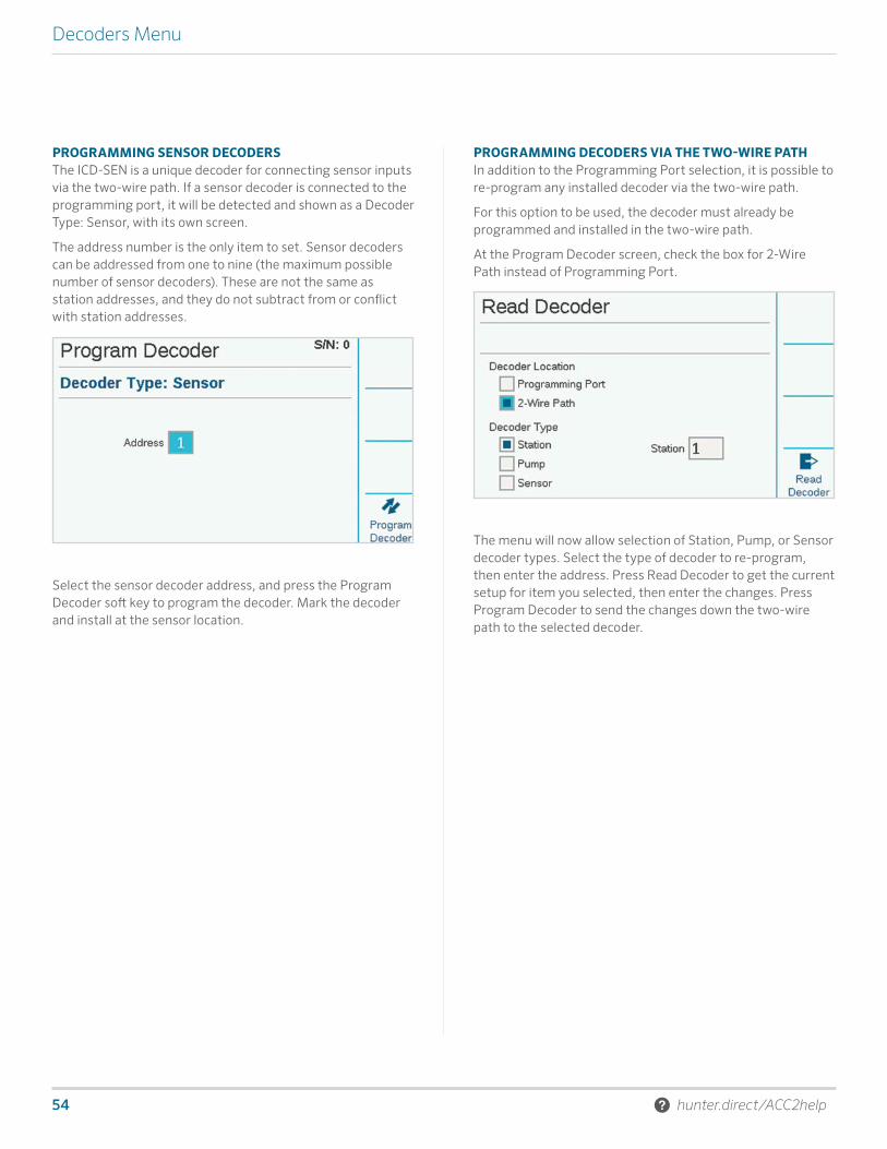
54 hunter.direct/ACC2help
Decoders Menu
PROGRAMMING SENSOR DECODERS The ICD-SEN is a unique decoder for connecting sensor inputs via the two-wire path. If a sensor decoder is connected to the programming port, it will be detected and shown as a Decoder Type: Sensor, with its own screen.
The address number is the only item to set. Sensor decoders can be addressed from one to nine (the maximum possible number of sensor decoders). These are not the same as station addresses, and they do not subtract from or conflict with station addresses.
Select the sensor decoder address, and press the Program Decoder soft key to program the decoder. Mark the decoder and install at the sensor location.
PROGRAMMING DECODERS VIA THE TWO-WIRE PATHIn addition to the Programming Port selection, it is possible to re-program any installed decoder via the two-wire path.
For this option to be used, the decoder must already be programmed and installed in the two-wire path.
At the Program Decoder screen, check the box for 2-Wire Path instead of Programming Port.
The menu will now allow selection of Station, Pump, or Sensor decoder types. Select the type of decoder to re-program, then enter the address. Press Read Decoder to get the current setup for item you selected, then enter the changes. Press Program Decoder to send the changes down the two-wire path to the selected decoder.

Built on Innovation® 55
Decoders Menu
VIEW CONFIGURATION
View Configuration can retrieve all the setup information for a specified decoder on the two-wire path, or for one attached to the programming port. It is similar to the Read Decoder function in the Program Decoder screens, except that it only retrieves information, and does not allow it to be changed.
View Configuration also retrieves the current firmware version of the selected decoder.
View Configuration also retrieves complete Port setup information for sensor decoders.
VIEW STATUS
View Status can target any station or P/MV decoder and show the current activity and electrical status of the device.
Select Station or P/MV.
Enter Station or P/MV number, and press Read Decoder.
The screen will show status, current draw, voltage on the two-wire path at the decoder location, whether a load (solenoid or relay) is present, and whether or not the station is active.
DECODER VIEWThe Decoder View soft key shows the status organized by station outputs within the selected decoder.
Each color-coded wire pair from the decoder will show its own status.

56 hunter.direct/ACC2help
Decoders Menu
STATION ASSIGNMENTS
When multiple decoder output modules are present, the range of station numbers allowed on each one can be changed, or “mapped.” This allows you to assign more than 75 stations to a decoder output module when necessary, to take advantage of the field wiring layout, as long as another module is present in the controller.
Each output module provides 75 stations when it is installed. If you need more than 75 stations on a single two-wire path, or on paths from a single module, you can reassign the station numbers from the other module(s) to the first module, and so on.
Check the box to enable station assignment changes, and click to confirm.
Each module will be shown with the range of station numbers assigned to it. At first, each will have 75 stations.
Select the Upper field for Decoder Module #1 to adjust the Upper station range up or down. As you adjust it, you’ll see the range of Decoder Module #2 changing by a corresponding amount.
If you set the range of the first module to less than 75 stations, the remaining stations are available to be assigned to module #2.
If you set the upper range of the first module higher than 75 stations, those stations are removed from module #2.
In this way, you can specify how many stations are available on each decoder output module.
You can click the Reset soft key to reset the modules to 75 stations each.
The more stations you assign to a single decoder output module, the higher the standby current draw on that module. This means that you may not be able to run as many active stations simultaneously with very high station counts on a single module.
DECODER DIAGNOSTICS
The Diagnostics screen displays an overview of the electrical status of each installed output module, plus additional functions.
Each module’s electrical current is shown. When no stations are running (Inactive), this shows the standby current draw of idle decoders on the two-wire path.
When stations are running (Active), the total current is updated to show the power used by the solenoids. Current is very helpful in troubleshooting field wiring conditions.
STATION FINDERThe station finder will chatter a selected station to help locate a solenoid in the field by listening.
Press the Station Finder soft key, and select the station number to locate. When the Start button is pressed, the controller will chatter the solenoid for up to 30 minutes. A technician can then listen for the underground noise to locate the selected solenoid.
To stop the chatter, press the soft key again, or it will stop by itself after 30 minutes.

Built on Innovation® 57
Decoders Menu
WIRE TESTThe wire test will place a 60 Hz frequency on all output modules and their two-wire paths, to allow wire tracking and fault finding with a standard AC current clamp meter. This is a common diagnostic technique to find shorts to earth ground.
The AC current will drop sharply between two points on the wire path, if the short circuit or fault to earth is between them.
When troubleshooting is finished, press the soft key again to turn off the 60 Hz wire test mode.
DECODER INVENTORY
This runs a test communication to all decoder addresses on the selected output module to verify which decoders are installed and operational on the two-wire paths. Use the inventory when station performance issues are suspected, or when assessing a new or undocumented control system.
To start the inventory, press the Update soft key. The controller will look for station addresses on all modules, and wait for responses. The process may take several minutes.
At the end of the inventory, the screen will show a report of all decoders found, with a screen for each individual decoder output module.
The report will indicate decoder type, station number, success rate (comm %) and the firmware update status, by decoder output module.
Use the Next Module soft key to view the results on each module, one at a time.
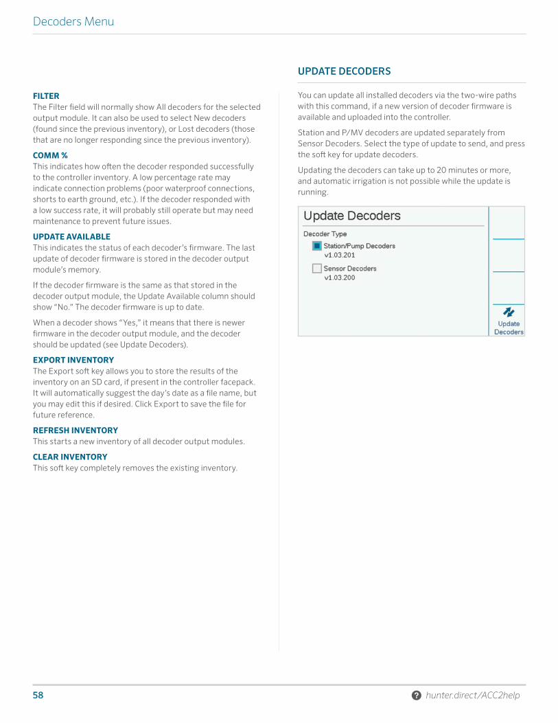
58 hunter.direct/ACC2help
Decoders Menu
FILTERThe Filter field will normally show All decoders for the selected output module. It can also be used to select New decoders (found since the previous inventory), or Lost decoders (those that are no longer responding since the previous inventory).
COMM %This indicates how often the decoder responded successfully to the controller inventory. A low percentage rate may indicate connection problems (poor waterproof connections, shorts to earth ground, etc.). If the decoder responded with a low success rate, it will probably still operate but may need maintenance to prevent future issues.
UPDATE AVAILABLEThis indicates the status of each decoder’s firmware. The last update of decoder firmware is stored in the decoder output module’s memory.
If the decoder firmware is the same as that stored in the decoder output module, the Update Available column should show “No.” The decoder firmware is up to date.
When a decoder shows “Yes,” it means that there is newer firmware in the decoder output module, and the decoder should be updated (see Update Decoders).
EXPORT INVENTORYThe Export soft key allows you to store the results of the inventory on an SD card, if present in the controller facepack. It will automatically suggest the day’s date as a file name, but you may edit this if desired. Click Export to save the file for future reference.
REFRESH INVENTORYThis starts a new inventory of all decoder output modules.
CLEAR INVENTORYThis soft key completely removes the existing inventory.
UPDATE DECODERS
You can update all installed decoders via the two-wire paths with this command, if a new version of decoder firmware is available and uploaded into the controller.
Station and P/MV decoders are updated separately from Sensor Decoders. Select the type of update to send, and press the soft key for update decoders.
Updating the decoders can take up to 20 minutes or more, and automatic irrigation is not possible while the update is running.

Built on Innovation® 59
Troubleshooting
Troubleshooting
Symptom Solution
Attention messagesPress View Messages and/or View Logs
Continue troubleshooting based on log reports
Non-Water Window violation Review program start time and Non-Water Window setup
Won’t run programs/stations Review Program or Station Summary
No display
Make sure facepack cable is connected
Make sure slide locks are closed
Make sure power is on to controller
Check Power Supply Board status light
Check transformer fuse
Overflow messagesVerify flow limits and delays allow for some variation
Check system for leaks and malfunctions
Won’t read flow
Check flow sensor wiring
Check flow sensor setup
Review Hydraulic Summary
Electrical or module malfunctions Go to Diagnostics menu, review all components
Communications failure (decoder)Decoder not responding; check wire path connection, wire path resistance, and decoder

RESIDENTIAL & COMMERCIAL IRRIGATION | Built on Innovation®
1940 Diamond Street, San Marcos, California 92078, USALearn more. Visit hunterindustries.com
© 2017 Hunter Industries Incorporated Please recycle. RC-035 EN 10/17
Helping our customers succeed is what drives us. While our passion for innovation and
engineering is built into everything we do, it is our commitment to exceptional support
that we hope will keep you in the Hunter family of customers for years to come.
Gregory R. Hunter, President of Hunter Industries


![Research Article Fast Maximum-Likelihood Decoder for Quasi ...downloads.hindawi.com/journals/mpe/2015/654865.pdf · QR [ ] decoders are more complex because their search spaces cannot](https://img.pdfslide.us/doc/110x75/6060d85e5ac72063b7784a61/research-article-fast-maximum-likelihood-decoder-for-quasi-qr-decoders-are.jpg)