Embed Size (px)
Citation preview


Adaptive beamforming using QR in FPGARichard Walke, Real-time System LabAdvanced Processing CentreS&E Division

3
Contents
1 Architecture of adaptive beamformer
2 FPGA components
• Digital receiver
• QR processor – for adaptive weight calculation
3 Design methodology
4 Demonstration overview
5 Conclusions

Architecture of adaptive beamformerSection 1

5
Rx
Beamformedsignal
Antenna Array
Analogue receivers
DRx
DRx
DRx
Rx
Rx
Digital receivers
Adaptive Weight Calculation
+
W1
W2
WnSpatial filter
Adaptive beamformerArchitecture of adaptive beamformer

FPGA componentsSection 2

7
Runtime configuration parameters
π2
Imagereject
Bandwidthcontrol
Complexequaliser
Imagereject
Bandwidthcontrol
Imagereject
Bandwidthcontrol
Imagereject
Bandwidthcontrol
Radar receiver specification
Array of programmable ‘tap-processors’
Software configurable FIRFPGA Components

8
• Software programmable parameters include:
– filter length
– decimation ratio
– complex/real arithmetic
– number of channels
– time varying filtering (inter & intra-pulse)
• Performance 20-30 GOPS on XC2V6000-5
– 100 GOPS on Virtex2 Pro (2003)
FPGA Components
Software configurable FIR
9
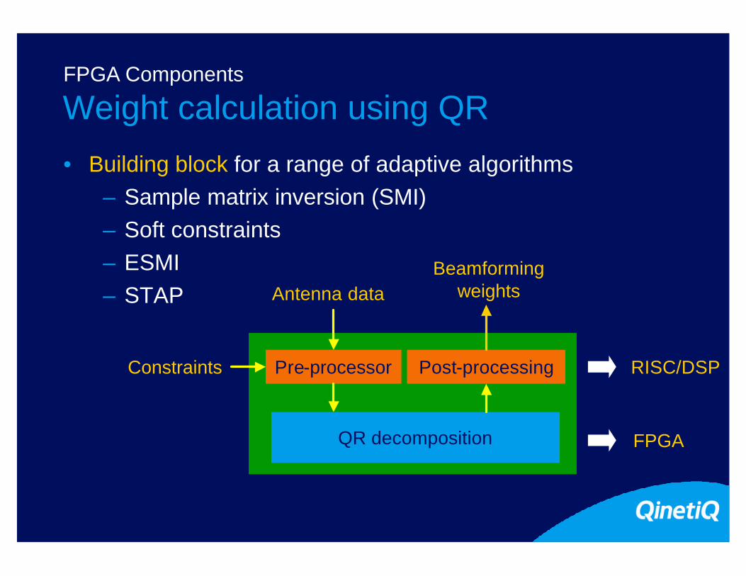
• Building block for a range of adaptive algorithms– Sample matrix inversion (SMI)– Soft constraints– ESMI– STAP
Pre-processor Post-processing
QR decomposition
RISC/DSP
FPGA
BeamformingweightsAntenna data
Constraints
Weight calculation using QRFPGA Components

10
QR decompositionFPGA Components
r2,2 r2,3
x1 y
r1,1 u1r1,2 r1,3 r1,4
r2,4 u2
u3r3,4r3,3
r4,4 u4
x2 x3 x4
Input dataVectorise cell:11 real floating-point operations
Rotate cell:16 real floating-pointoperations
For SMI: Rw=u
θ
(r,x)
(r’,0)
cos θ =r
r2+x2
sin θ =x
r2+x2
θ
(u,y)(u’,y’)
u’y’ =
uy
cos θ sin θ-sin θ cos θ

11
• Good numerical properties. Arithmetic choices:
– CORDIC: shift-add
– Fixed-point: multiply-add
– Floating-point: Higher dynamic range, allows algorithms with fewer operations & lower wordlength. Smallest!
• Highly parallel (Givens rotations)
– Suits FPGA
– Need to reduce parallelism for many applications!
Features of QRFPGA Components
12
1,1 1,31,2 1,4 1,5
2,2 2,42,3 2,5
3,3 3,53,4
4,4 4,5
1,6
2,6
3,6
4,6
5,5 5,6
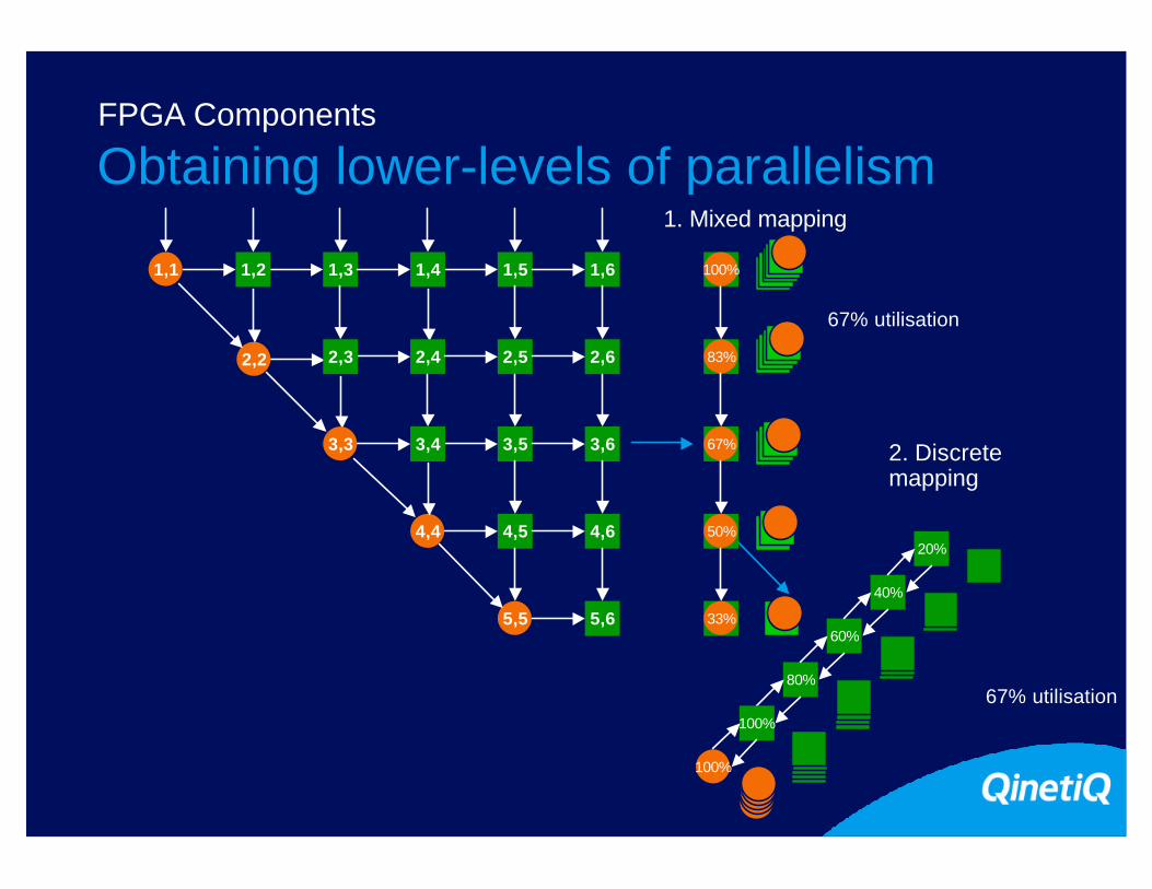
2. Discretemapping
67% utilisation80%
60%
40%
20%
100%
100%
83%
67%
50%
33%
100%
67% utilisation
1. Mixed mapping
Obtaining lower-levels of parallelismFPGA Components

13
Linear systolic array
Novel mapping of QRFPGA Components

14
FPGA implementation
16
16
11
16
16
16
16
16
16
139 14-bit FP operators @ 160MHz = 22 GFLOPSNumber of Ops
8xFP multipliers
2 x
complex
adder
Complex
multiplier
FP
addFP divider vectorise
processor
rotate
processor
rotate
processor
rotate
processor
rotate
processor
rotate
processor
rotate
processor
rotate
processor
FP
add
Complex
multiplier
XCV3200E-8
FPGA Components

15
QR processor - main featuresFPGA Components
1 Boundary3 Internal
32
23% 6 GFLOPS 2.24W 4
1 Boundary12 Internal 82%2 20.3 GFLOPS 8W6
LUTSRams3
FFs
Mults34
15K16K
22%23%22%23%
4 GFLOPS 70WPentiumTM 4 2GHz1
1 Estimated (based on data from Richard Linderman)2 Estimated (design too large for PC)3 Also depends upon number of inputs4 Obtained via Xpower5 For XC2V6000-56 Extrapolated
101MHz5
1 Boundary9 Internal 74% 15 GFLOPS 7W6
14-bit mantissa
17-bit mantissa
14-bit mantissa
97MHz
100MHz2
Size Utilisation (XC2V6000) Operations PowerMantissa wordlength Clock
x50

Heterogeneous design methodologySection 3

17
GEDAETMHeterogeneous design methodology
• Graphically specify system

18
GEDAETMHeterogeneous design methodology
• Graphically specify system
– primitive functions in ‘c’

19
GEDAETMHeterogeneous design methodology
• Graphically specify system
– primitive functions in ‘c’
– executable specification

20
GEDAETMHeterogeneous design methodology
• Graphically specify system
– primitive functions in ‘c’
– executable specification
• Auto-code generation
– parallel programme constructed by GEDAE

21
GEDAETMHeterogeneous design methodology
• Graphically specify system
– primitive functions in ‘c’
– executable specification
• Auto-code generation
– parallel programme constructed by GEDAE
• Currently no support for FPGA
– highly compatible model

22
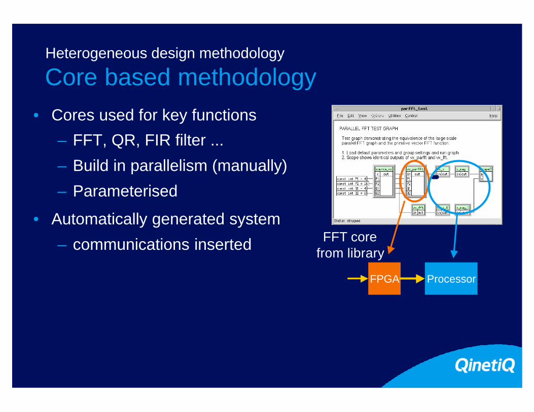
Core based methodologyHeterogeneous design methodology
• Cores used for key functions
– FFT, QR, FIR filter ...
– Build in parallelism (manually)
– Parameterised Processor
23
Core based methodologyHeterogeneous design methodology
• Cores used for key functions
– FFT, QR, FIR filter ...
– Build in parallelism (manually)
– Parameterised
• Automatically generated system
– communications inserted
FPGA
Processor
Processor
FFT core from library

24
Core based methodologyHeterogeneous design methodology
• Cores used for key functions
– FFT, QR, FIR filter ...
– Build in parallelism (manually)
– Parameterised
• Automatically generated system
– communications inserted
• Architectural exploration
– Compaan gives Matlab NLP to VHDL
– RTL output in future version
FPGA
Processor
Processor
FFT core from library

Adaptive beamformer demonstration overview
Section 4

26
System mappingDemonstration overview
Delay
Sample
PCI IF
Virtual channel IF
Chan0 Chan1
FPGA (TransTech PMC)
Chan2 Chan3
QRDRx
Virtual Channel API
PowerPC (DNA VQG4 VME)
Back-substitution
Host PC (laptop)
Environment synthesis
and system configuration
Host PC (laptop)
Verification and display

27
Conclusion
• FPGAs
– Performance dependent upon level of optimisation
– Floating-point is realistic
– 10x compute improvement
– 5 - 20x power improvement
• Design is main issue
– Hardware design: High levels of parallelism required
– Core-based design approaches offer interim solution
– Architectural synthesis tools are emerging

28
Acknowledgements
• The project to develop a core-based design methodology is a collaboration between:
– QinetiQ Ltd
• poc: [email protected]
– BAE SYSTEMS ATC, Gt Baddow
• poc: [email protected]
• Contributions have been made by John McAllister under contract with the Queen’s University of Belfast.
• This work was sponsored by the United Kingdom Ministry of Defence Corporate Research Programme.