Embed Size (px)
Citation preview
SOLIDYNE SRL3 de Febrero 3254 (C.P. 1429)
Buenos Aires - Argentina
Tel.: +54 11 4702 0090Fax: +54 11 4702 2375
ADA102 CODER - DECODERTCP/IP studio-to-transmitter link
User's manual
Last revision: May 2011Firmware 2.05

Table of contents
Overview - ADA102 CODER / DECODER . .51.1 About this manual..................................................51.2 What's in the box?..................................................51.3 Features..................................................................5
Section 1 - Hardware and connections .....7
1.1 General connection diagram ..................7
1.2 Rear panel.................................................71.2.1 Power supply.......................................................71.2.2 Audio inputs and outputs...................................7
Balanced input/output connections:......................................7Unbalanced connections: .....................................................7
1.2.3 LAN port...............................................................81.2.4 USB port...............................................................81.2.5 Serial port.............................................................81.2.6 Remote control....................................................81.2.7 MPX output (optional ADA102mpx)...................81.2.8 Reset.....................................................................8
1.3 Frontal panel.............................................91.3.1 Level indicators...................................................9
1.3.1.1 VU mode Tx/Rx.........................................................91.3.2 SATUS LED's...............................................................9
1.3.2 Headphones output.............................................91.3.3 Input Gain.............................................................91.3.4 Output Gain..........................................................9
1.4 STL connection diagram........................111.4.1 Connection diagram for streaming transport..111.4.2 Levels adjustment.............................................11
1.4.2.1 Audio processor locates at the studios with analogical connections........................................................111.4.2.2 Full digital connections............................................121.4.2.3 Audio processor locates at transmission plant.......12
1.4.3 Using an RF digital link....................................12
Section 2 - Software settings....................13
2.1 ADA102 into the Studios – Brief guide..132.1.1 Entering to ADA102...........................................13
Step 1..............................................................................13Step 2..............................................................................13Step 3..............................................................................13Step 4..............................................................................13
2.1.2 Set the working mode.......................................132.1.3 Audio options....................................................13
Step 6..............................................................................132.1.4 Status screen (home)........................................14
2.2 ADA102 at the Transmitter PlantBrief guide ....................................................14
2.2.1 Instalation..........................................................14Step 1..............................................................................14Step 2..............................................................................14Step 3..............................................................................14Step 4..............................................................................14Step 5..............................................................................14Step 6..............................................................................14
2.2.2 ADA102 working as decoder............................14Step 7..............................................................................15Step 8..............................................................................15
2.2.3 Status screen.....................................................15
2.3 Advanced settings..................................172.3.1 Setting temporary IP address using ARP command ...................................................................172.3.2 Remote control..................................................182.3.3 Serial port...........................................................182.3.4 About audio settings.........................................19
Encoding & Frequency....................................................192.3.5 Calculating the bit rate......................................192.3.6 Emergency pendrive.........................................20
2.4 Other connection modes........................212.4.1 Half-duplex link with unknown IP at the transmitter plant.........................................................212.4.2 Full-duplex link with unknown IP at the Studios........................................................................212.4.3 Link with repeaters...........................................22
Section 3 - Technical specifications........23Digital Streaming Input / Output ..............................23Other features.............................................................24MPX output (modelo ADA102mpx)...........................24
SOLIDYNE ADA102 CODER/DECODER Page 3

SOLIDYNE ADA102 CODER/DECODER Page 4
Overview ADA102 CODER / DECODER
1.1 About this manual
Solidyne® All rights reserved. No part of this documentcan be copied or reproduced. All information is subject tochange without notice. All mentioned trademarks belongto their respective owners and are used for reference only.
The exclamation icon within a triangle that appears in this manual is intended to alert the user to the presence of important instructions on the operation and maintenance (servicing) of the equipment.
The pencil icon that appears in this manual is to alert the user to the presence of notes, suggestions and examplesabout the operation.
1.2 What's in the box?
Inside the box you will find the following:
• 1 ADA102 Encoder / Decoder (rack module).-• 1 AC power cord.-• 1 crossed LAN cable • Printed user manual (this manual).-• Warranty certificate.-
Please check the items when receive it to verify that allcomponents are okay.
1.3 Features
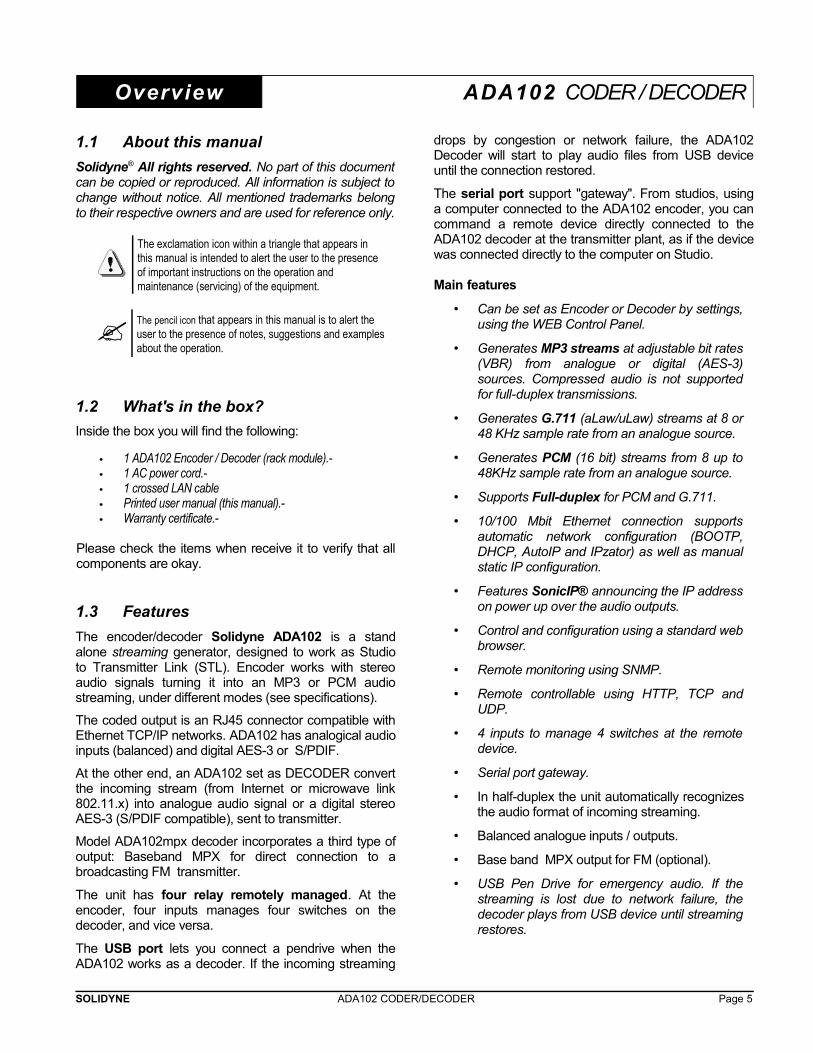
The encoder/decoder Solidyne ADA102 is a standalone streaming generator, designed to work as Studioto Transmitter Link (STL). Encoder works with stereoaudio signals turning it into an MP3 or PCM audiostreaming, under different modes (see specifications).
The coded output is an RJ45 connector compatible withEthernet TCP/IP networks. ADA102 has analogical audioinputs (balanced) and digital AES-3 or S/PDIF.
At the other end, an ADA102 set as DECODER convertthe incoming stream (from Internet or microwave link802.11.x) into analogue audio signal or a digital stereoAES-3 (S/PDIF compatible), sent to transmitter.
Model ADA102mpx decoder incorporates a third type ofoutput: Baseband MPX for direct connection to abroadcasting FM transmitter.
The unit has four relay remotely managed. At theencoder, four inputs manages four switches on thedecoder, and vice versa.
The USB port lets you connect a pendrive when theADA102 works as a decoder. If the incoming streaming
drops by congestion or network failure, the ADA102Decoder will start to play audio files from USB deviceuntil the connection restored.
The serial port support "gateway". From studios, usinga computer connected to the ADA102 encoder, you cancommand a remote device directly connected to theADA102 decoder at the transmitter plant, as if the devicewas connected directly to the computer on Studio.
Main features
• Can be set as Encoder or Decoder by settings,using the WEB Control Panel.
• Generates MP3 streams at adjustable bit rates(VBR) from analogue or digital (AES-3)sources. Compressed audio is not supportedfor full-duplex transmissions.
• Generates G.711 (aLaw/uLaw) streams at 8 or48 KHz sample rate from an analogue source.
• Generates PCM (16 bit) streams from 8 up to48KHz sample rate from an analogue source.
• Supports Full-duplex for PCM and G.711.
• 10/100 Mbit Ethernet connection supportsautomatic network configuration (BOOTP,DHCP, AutoIP and IPzator) as well as manualstatic IP configuration.
• Features SonicIP® announcing the IP addresson power up over the audio outputs.
• Control and configuration using a standard webbrowser.
• Remote monitoring using SNMP.
• Remote controllable using HTTP, TCP andUDP.
• 4 inputs to manage 4 switches at the remotedevice.
• Serial port gateway.
• In half-duplex the unit automatically recognizesthe audio format of incoming streaming.
• Balanced analogue inputs / outputs.
• Base band MPX output for FM (optional).
• USB Pen Drive for emergency audio. If thestreaming is lost due to network failure, thedecoder plays from USB device until streamingrestores.
SOLIDYNE ADA102 CODER/DECODER Page 5

SOLIDYNE ADA102 CODER/DECODER Page 6
Section 1 Hardware and connections
1.1 General connection diagram
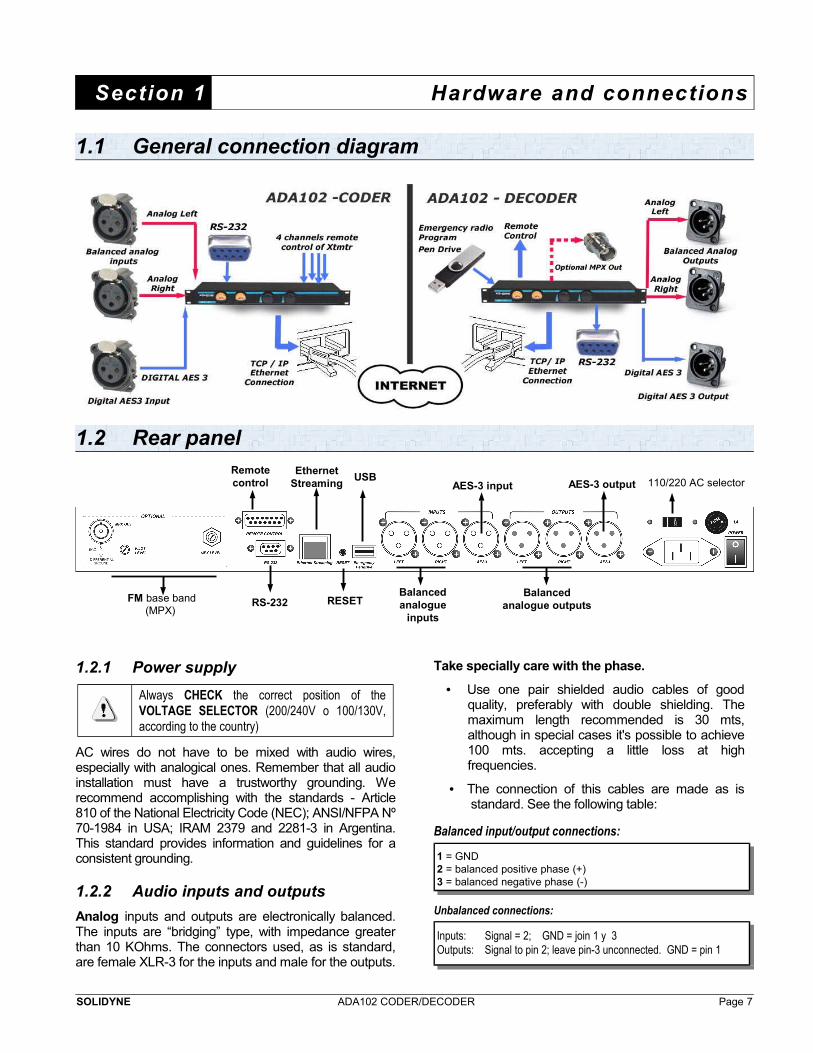
1.2 Rear panel
1.2.1 Power supply
Always CHECK the correct position of theVOLTAGE SELECTOR (200/240V o 100/130V,according to the country)
AC wires do not have to be mixed with audio wires,especially with analogical ones. Remember that all audioinstallation must have a trustworthy grounding. Werecommend accomplishing with the standards - Article810 of the National Electricity Code (NEC); ANSI/NFPA Nº70-1984 in USA; IRAM 2379 and 2281-3 in Argentina.This standard provides information and guidelines for aconsistent grounding.
1.2.2 Audio inputs and outputs
Analog inputs and outputs are electronically balanced.The inputs are “bridging” type, with impedance greaterthan 10 KOhms. The connectors used, as is standard,are female XLR-3 for the inputs and male for the outputs.
Take specially care with the phase.
• Use one pair shielded audio cables of goodquality, preferably with double shielding. Themaximum length recommended is 30 mts,although in special cases it's possible to achieve100 mts. accepting a little loss at highfrequencies.
• The connection of this cables are made as isstandard. See the following table:
Balanced input/output connections:
1 = GND2 = balanced positive phase (+) 3 = balanced negative phase (-)
Unbalanced connections:
Inputs: Signal = 2; GND = join 1 y 3Outputs: Signal to pin 2; leave pin-3 unconnected. GND = pin 1
SOLIDYNE ADA102 CODER/DECODER Page 7
FM base band (MPX)
RS-232
AES-3 input AES-3 output
Balanced analogue
inputs
Balanced analogue outputs
110/220 AC selectorUSB
RESET
Ethernet Streaming
Remotecontrol
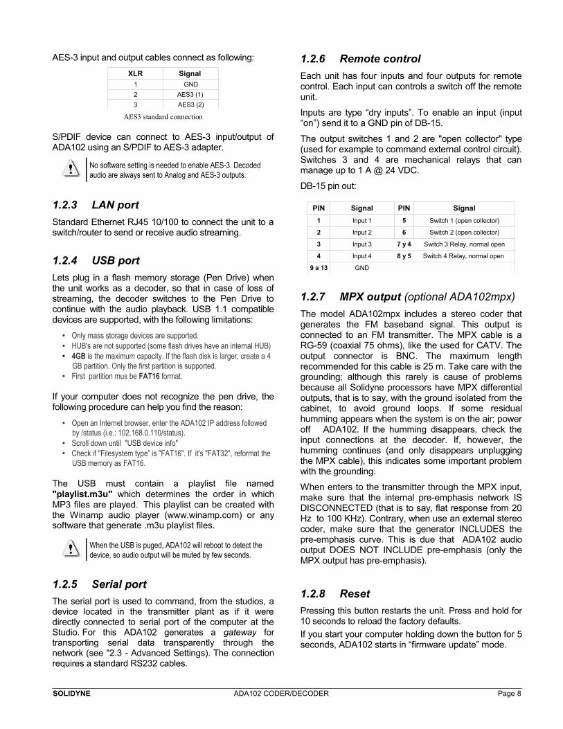
AES-3 input and output cables connect as following:
XLR Signal
1 GND
2 AES3 (1)
3 AES3 (2)
AES3 standard connection
S/PDIF device can connect to AES-3 input/output ofADA102 using an S/PDIF to AES-3 adapter.
No software setting is needed to enable AES-3. Decoded audio are always sent to Analog and AES-3 outputs.
1.2.3 LAN port
Standard Ethernet RJ45 10/100 to connect the unit to aswitch/router to send or receive audio streaming.
1.2.4 USB port
Lets plug in a flash memory storage (Pen Drive) whenthe unit works as a decoder, so that in case of loss ofstreaming, the decoder switches to the Pen Drive tocontinue with the audio playback. USB 1.1 compatibledevices are supported, with the following limitations:
• Only mass storage devices are supported.• HUB's are not supported (some flash drives have an internal HUB)• 4GB is the maximum capacity. If the flash disk is larger, create a 4
GB partition. Only the first partition is supported. • First partition mus be FAT16 format.
If your computer does not recognize the pen drive, thefollowing procedure can help you find the reason:
• Open an Internet browser, enter the ADA102 IP address followed by /status (i.e.: 102.168.0.110/status).
• Scroll down until "USB device info"• Check if "Filesystem type” is "FAT16". If it's "FAT32", reformat the
USB memory as FAT16.
The USB must contain a playlist file named"playlist.m3u" which determines the order in whichMP3 files are played. This playlist can be created withthe Winamp audio player (www.winamp.com) or anysoftware that generate .m3u playlist files.
When the USB is puged, ADA102 will reboot to detect the device, so audio output will be muted by few seconds.
1.2.5 Serial port
The serial port is used to command, from the studios, adevice located in the transmitter plant as if it weredirectly connected to serial port of the computer at theStudio. For this ADA102 generates a gateway fortransporting serial data transparently through thenetwork (see "2.3 - Advanced Settings). The connectionrequires a standard RS232 cables.
1.2.6 Remote control
Each unit has four inputs and four outputs for remotecontrol. Each input can controls a switch off the remoteunit.
Inputs are type “dry inputs”. To enable an input (input“on”) send it to a GND pin of DB-15.
The output switches 1 and 2 are "open collector" type(used for example to command external control circuit).Switches 3 and 4 are mechanical relays that canmanage up to 1 A @ 24 VDC.
DB-15 pin out:
PIN Signal PIN Signal
1 Input 1 5 Switch 1 (open collector)
2 Input 2 6 Switch 2 (open collector)
3 Input 3 7 y 4 Switch 3 Relay, normal open
4 Input 4 8 y 5 Switch 4 Relay, normal open
9 a 13 GND
1.2.7 MPX output (optional ADA102mpx)
The model ADA102mpx includes a stereo coder thatgenerates the FM baseband signal. This output isconnected to an FM transmitter. The MPX cable is aRG-59 (coaxial 75 ohms), like the used for CATV. Theoutput connector is BNC. The maximum lengthrecommended for this cable is 25 m. Take care with thegrounding; although this rarely is cause of problemsbecause all Solidyne processors have MPX differentialoutputs, that is to say, with the ground isolated from thecabinet, to avoid ground loops. If some residualhumming appears when the system is on the air; poweroff ADA102. If the humming disappears, check theinput connections at the decoder. If, however, thehumming continues (and only disappears unpluggingthe MPX cable), this indicates some important problemwith the grounding.
When enters to the transmitter through the MPX input,make sure that the internal pre-emphasis network ISDISCONNECTED (that is to say, flat response from 20Hz to 100 KHz). Contrary, when use an external stereocoder, make sure that the generator INCLUDES thepre-emphasis curve. This is due that ADA102 audiooutput DOES NOT INCLUDE pre-emphasis (only theMPX output has pre-emphasis).
1.2.8 Reset
Pressing this button restarts the unit. Press and hold for10 seconds to reload the factory defaults.
If you start your computer holding down the button for 5seconds, ADA102 starts in “firmware update” mode.
SOLIDYNE ADA102 CODER/DECODER Page 8
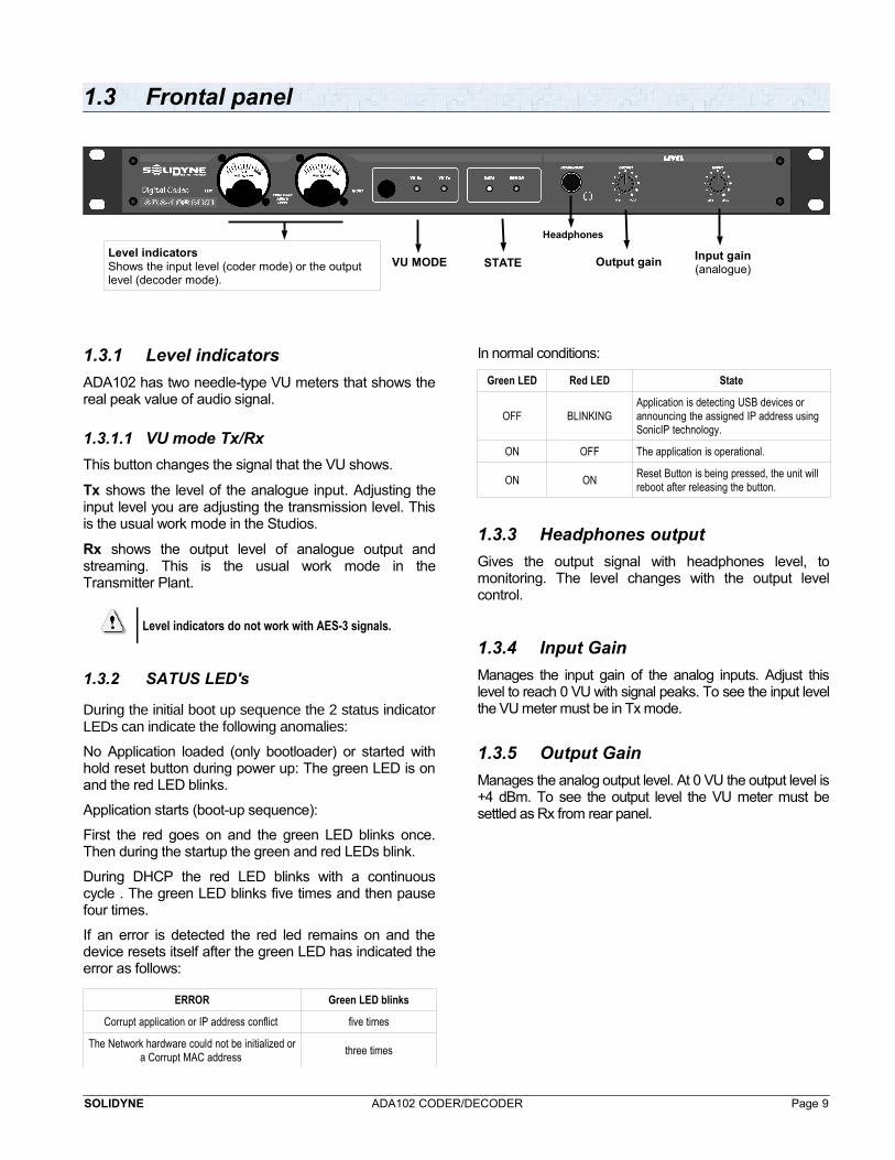
1.3 Frontal panel
1.3.1 Level indicators
ADA102 has two needle-type VU meters that shows thereal peak value of audio signal.
1.3.1.1 VU mode Tx/Rx
This button changes the signal that the VU shows.
Tx shows the level of the analogue input. Adjusting theinput level you are adjusting the transmission level. Thisis the usual work mode in the Studios.
Rx shows the output level of analogue output andstreaming. This is the usual work mode in theTransmitter Plant.
Level indicators do not work with AES-3 signals.
1.3.2 SATUS LED's
During the initial boot up sequence the 2 status indicatorLEDs can indicate the following anomalies:
No Application loaded (only bootloader) or started withhold reset button during power up: The green LED is onand the red LED blinks.
Application starts (boot-up sequence):
First the red goes on and the green LED blinks once.Then during the startup the green and red LEDs blink.
During DHCP the red LED blinks with a continuouscycle . The green LED blinks five times and then pausefour times.
If an error is detected the red led remains on and thedevice resets itself after the green LED has indicated theerror as follows:
ERROR Green LED blinks
Corrupt application or IP address conflict five times
The Network hardware could not be initialized ora Corrupt MAC address
three times
In normal conditions:
Green LED Red LED State
OFF BLINKINGApplication is detecting USB devices or announcing the assigned IP address using SonicIP technology.
ON OFF The application is operational.
ON ONReset Button is being pressed, the unit will reboot after releasing the button.
1.3.3 Headphones output
Gives the output signal with headphones level, tomonitoring. The level changes with the output levelcontrol.
1.3.4 Input Gain
Manages the input gain of the analog inputs. Adjust thislevel to reach 0 VU with signal peaks. To see the input levelthe VU meter must be in Tx mode.
1.3.5 Output Gain
Manages the analog output level. At 0 VU the output level is+4 dBm. To see the output level the VU meter must besettled as Rx from rear panel.
SOLIDYNE ADA102 CODER/DECODER Page 9
Level indicatorsShows the input level (coder mode) or the output level (decoder mode).
Input gain(analogue)
Output gainSTATEVU MODE
Headphones

SOLIDYNE ADA102 CODER/DECODER Page 10
1.4 STL connection diagram
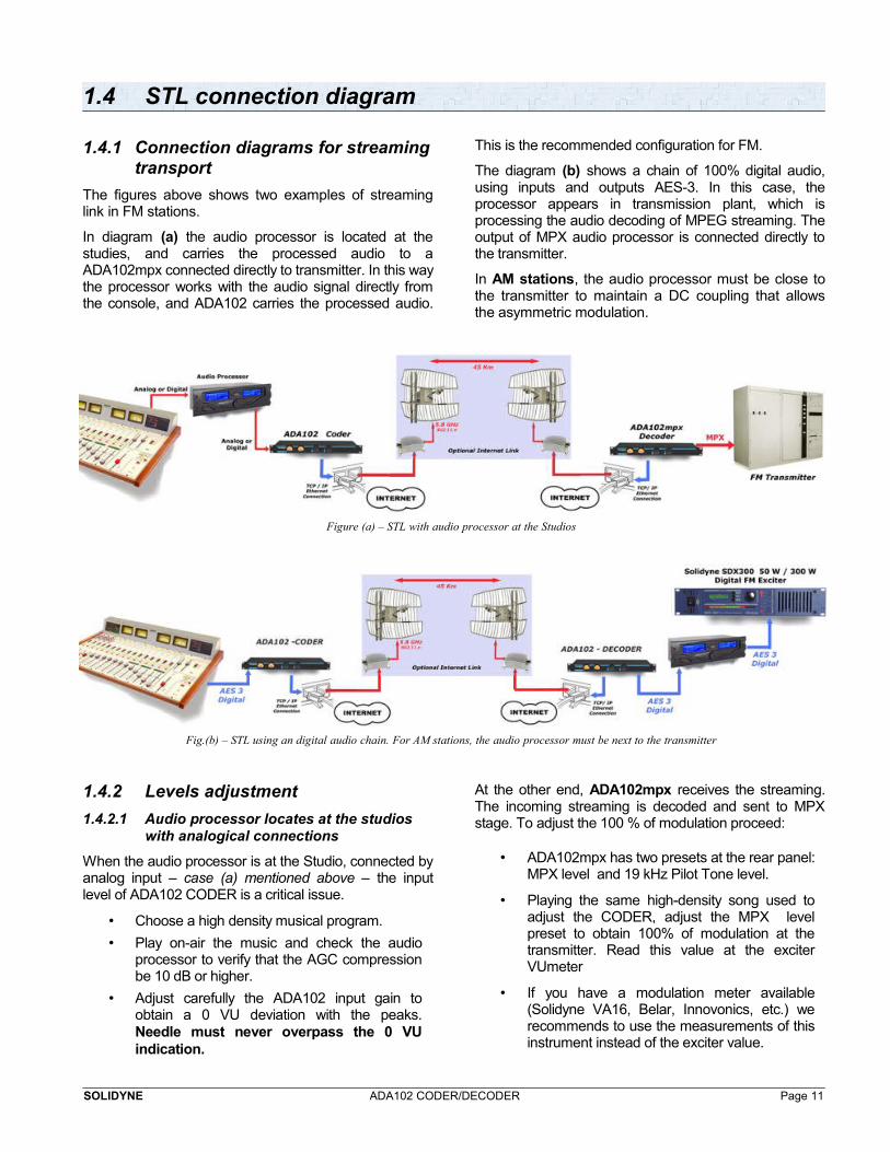
1.4.1 Connection diagrams for streamingtransport
The figures above shows two examples of streaminglink in FM stations.
In diagram (a) the audio processor is located at thestudies, and carries the processed audio to aADA102mpx connected directly to transmitter. In this waythe processor works with the audio signal directly fromthe console, and ADA102 carries the processed audio.
This is the recommended configuration for FM.
The diagram (b) shows a chain of 100% digital audio,using inputs and outputs AES-3. In this case, theprocessor appears in transmission plant, which isprocessing the audio decoding of MPEG streaming. Theoutput of MPX audio processor is connected directly tothe transmitter.
In AM stations, the audio processor must be close tothe transmitter to maintain a DC coupling that allowsthe asymmetric modulation.
Figure (a) – STL with audio processor at the Studios
Fig.(b) – STL using an digital audio chain. For AM stations, the audio processor must be next to the transmitter
1.4.2 Levels adjustment
1.4.2.1 Audio processor locates at the studios with analogical connections
When the audio processor is at the Studio, connected byanalog input – case (a) mentioned above – the inputlevel of ADA102 CODER is a critical issue.
• Choose a high density musical program.
• Play on-air the music and check the audioprocessor to verify that the AGC compressionbe 10 dB or higher.
• Adjust carefully the ADA102 input gain toobtain a 0 VU deviation with the peaks.Needle must never overpass the 0 VUindication.
At the other end, ADA102mpx receives the streaming.The incoming streaming is decoded and sent to MPXstage. To adjust the 100 % of modulation proceed:
• ADA102mpx has two presets at the rear panel:MPX level and 19 kHz Pilot Tone level.
• Playing the same high-density song used toadjust the CODER, adjust the MPX levelpreset to obtain 100% of modulation at thetransmitter. Read this value at the exciterVUmeter
• If you have a modulation meter available(Solidyne VA16, Belar, Innovonics, etc.) werecommends to use the measurements of thisinstrument instead of the exciter value.
SOLIDYNE ADA102 CODER/DECODER Page 11
• If you have a modulation meter available,adjust the pilot tone depth to 8% / 10% usingthe correspondent preset of ADA102mpx. Ifyou don't have a modulation meter, do notchange this preset.
Do not push the screwdriver. The preset can be broken.
The level knob at the ADA102mpx front panel do notchanges the MPX level. Only take effect on the level ofbalanced outputs, so it must be adjusted only to obtain avisualization at the VU-meters, which will indicate thatinput streaming is present.
The internal input gain (software) do not be changed.It must be -1 dB (default value).
1.4.2.2 Full digital connections
Whenever the audio processor is located, in a full digitalaudio chain – case (b) mentioned above – the controlson frontal pannel do not take effect over the signal. Theadjustment is made from web control pannel. The levelof the digital audio is not changed by the encoding–decoding process.
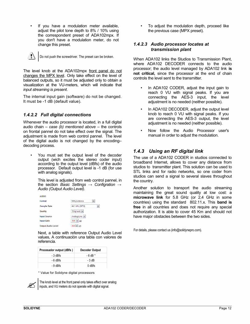
• You must set the output level of the decoderoutput (wich excites the stereo coder input)according to the output level (dBfs) of the audioprocessor. Default output level is -1 dB (for usewith analog signals).
This level is adjusted from web control pannel, inthe section Basic Settings → Configration →Audio (Output Audio Level).
Next, a table with reference Output Audio Levelvalues, A continuación una tabla con valores dereferencia.
Procesador output (dBfs ) Decoder Output
- 3 dBfs - 6 dB *
- 6 dBfs - 3 dB
- 9 dBfs 0 dBfs
* Value for Solidyne digital processors
The knob level at the front panel only takes effect over analog inputs, and VU meters do not operate with digital signal.
• To adjust the modulation depth, proceed likethe previous case (MPX preset).
1.4.2.3 Audio processor locates at transmission plant
When ADA102 links the Studios to Transmission Plant,where ADA102 DECODER connects to the audioprocessor; the audio level managed by ADA102 link isnot critical, since the processor at the end of chaincontrols the level sent to the transmitter.
• In ADA102 CODER, adjust the input gain toreach 0 VU with signal peaks. If you areconnecting the AES-3 input, the leveladjustment is no needed (neither possible).
• In ADA102 DECODER, adjust the output levelknob to reach 0 VU with signal peaks. If youare connecting the AES-3 output, the leveladjustment is no needed (neither possible).
• Now follow the Audio Processor user'smanual in order to adjust the modulation.
1.4.3 Using an RF digital linkThe use of a ADA102 CODER in studios connected tobroadband Internet, allows to cover any distance fromstudios to transmitter plant. This solution can be used toSTL links and for radio networks, so one coder fromstudios can send a signal to several slaves throughoutthe country.
Another solution to transport the audio streamingmaintaining the great sound quality at low cost: amicrowave link for 5.8 GHz (or 2,4 GHz in somecountries) using the standard 802.11.x. This band isfree in all countries and does not require any specialauthorization. It is able to cover 45 Km and should nothave major obstacles between the two sides.
For details, please contact us ([email protected]).
SOLIDYNE ADA102 CODER/DECODER Page 12
Section 2 Software settings
2.1 ADA102 into the Studios – Brief guide
ADA102 can be settled to work as a coder, asdecoder, or both at once for full-duplex connections.In this example we assume a unidirectional link (half-duplex) between Studios and Transmitter Plant. In theStudios the ADA102 works as ENCODER, generatingand sending an audio streaming to the transmitter. Atthe transmitter plant ADA102 receives the streamingand decode it to audio.
2.1.1 Entering to ADA102
ADA102 is configured using a web browser. Bydefault, ADA102 uses "Dynamic IP" so that whenconnected to a LAN, gets an IP address via DHCP(the router assigns an IP). The procedure is asfollows:
Step 1Plug the unit to the LAN using a standard RJ45 cable.
Step 2Plug a headphone to the frontal panel connector.Please have your pen and paper to write the IPaddress that will be announced.
The level of the headphones is managed by the output gain knob. If you don't hear the IP, check this knob.
Step 3Power on ADA102 (main switch locates at the rearpanel). The ADA102 CODER will search for a DHCPserver to get an IP address. Once obtained the IP,your ADA102 is now ready to start working. Green Ledon front panel will blink.If no DHCP server is found then ADA102 will search the networkfor a free IP address (this could take up to 5 minutes). If all is right,DATA LED at the front panel will blink. If the front LED's (“data”and “error”) stay dark check the power cabling. If it still fails, pleasecontact to Solidyne.
Step 4Open an Internet browser (i.e. Firefox, InternetExplorer) and enter the announced IP address. Theweb control panel will appears on screen.
2.1.2 Set the working mode
The STATUS screen indicates the current settings. Goto the options that appears at the top of the window.Click on “Location” and choose 'Studio Encoder'.
Step 5
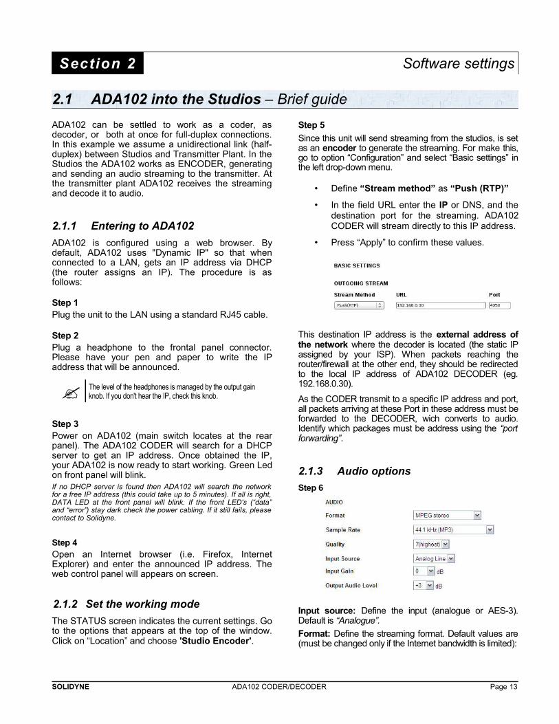
Since this unit will send streaming from the studios, is setas an encoder to generate the streaming. For make this,go to option “Configuration” and select “Basic settings” inthe left drop-down menu.
• Define “Stream method” as “Push (RTP)”
• In the field URL enter the IP or DNS, and thedestination port for the streaming. ADA102CODER will stream directly to this IP address.
• Press “Apply” to confirm these values.
This destination IP address is the external address ofthe network where the decoder is located (the static IPassigned by your ISP). When packets reaching therouter/firewall at the other end, they should be redirectedto the local IP address of ADA102 DECODER (eg.192.168.0.30).
As the CODER transmit to a specific IP address and port,all packets arriving at these Port in these address must beforwarded to the DECODER, wich converts to audio.Identify which packages must be address using the “portforwarding”.
2.1.3 Audio options
Step 6
Input source: Define the input (analogue or AES-3).Default is “Analogue”.
Format: Define the streaming format. Default values are(must be changed only if the Internet bandwidth is limited):
SOLIDYNE ADA102 CODER/DECODER Page 13
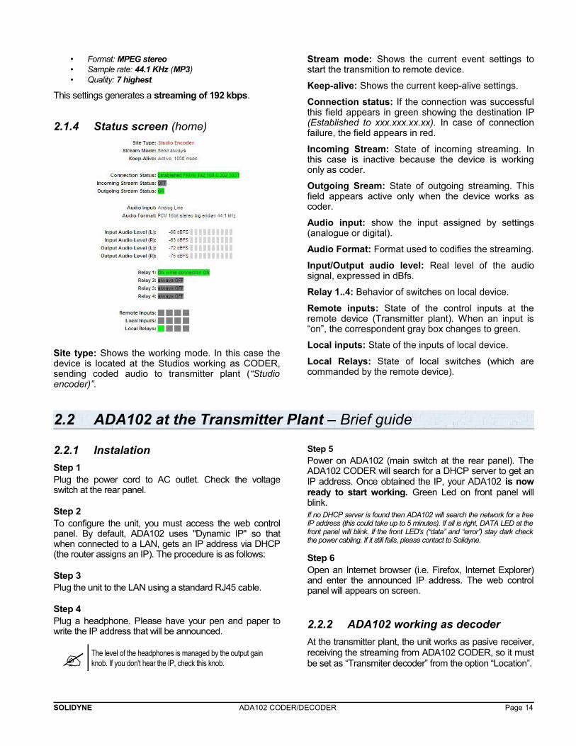
• Format: MPEG stereo• Sample rate: 44.1 KHz (MP3)• Quality: 7 highest
This settings generates a streaming of 192 kbps.
2.1.4 Status screen (home)
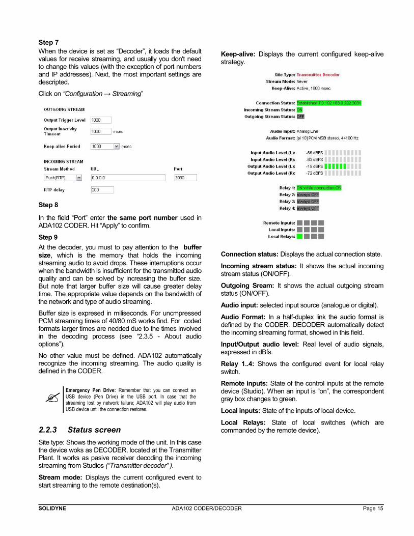
Site type: Shows the working mode. In this case thedevice is located at the Studios working as CODER,sending coded audio to transmitter plant (“Studioencoder)”.
Stream mode: Shows the current event settings tostart the transmition to remote device.
Keep-alive: Shows the current keep-alive settings.
Connection status: If the connection was successfulthis field appears in green showing the destination IP(Established to xxx.xxx.xx.xx). In case of connectionfailure, the field appears in red.
Incoming Stream: State of incoming streaming. Inthis case is inactive because the device is workingonly as coder.
Outgoing Sream: State of outgoing streaming. Thisfield appears active only when the device works ascoder.
Audio input: show the input assigned by settings(analogue or digital).
Audio Format: Format used to codifies the streaming.
Input/Output audio level: Real level of the audiosignal, expressed in dBfs.
Relay 1..4: Behavior of switches on local device.
Remote inputs: State of the control inputs at theremote device (Transmitter plant). When an input is“on”, the correspondent gray box changes to green.
Local inputs: State of the inputs of local device.
Local Relays: State of local switches (which arecommanded by the remote device).
2.2 ADA102 at the Transmitter Plant – Brief guide
2.2.1 Instalation
Step 1Plug the power cord to AC outlet. Check the voltageswitch at the rear panel.
Step 2To configure the unit, you must access the web controlpanel. By default, ADA102 uses "Dynamic IP" so thatwhen connected to a LAN, gets an IP address via DHCP(the router assigns an IP). The procedure is as follows:
Step 3Plug the unit to the LAN using a standard RJ45 cable.
Step 4Plug a headphone. Please have your pen and paper towrite the IP address that will be announced.
The level of the headphones is managed by the output gain knob. If you don't hear the IP, check this knob.
Step 5Power on ADA102 (main switch at the rear panel). TheADA102 CODER will search for a DHCP server to get anIP address. Once obtained the IP, your ADA102 is nowready to start working. Green Led on front panel willblink.If no DHCP server is found then ADA102 will search the network for a freeIP address (this could take up to 5 minutes). If all is right, DATA LED at thefront panel will blink. If the front LED's (“data” and “error”) stay dark checkthe power cabling. If it still fails, please contact to Solidyne.
Step 6Open an Internet browser (i.e. Firefox, Internet Explorer)and enter the announced IP address. The web controlpanel will appears on screen.
2.2.2 ADA102 working as decoder
At the transmitter plant, the unit works as pasive receiver,receiving the streaming from ADA102 CODER, so it mustbe set as “Transmiter decoder” from the option “Location”.
SOLIDYNE ADA102 CODER/DECODER Page 14
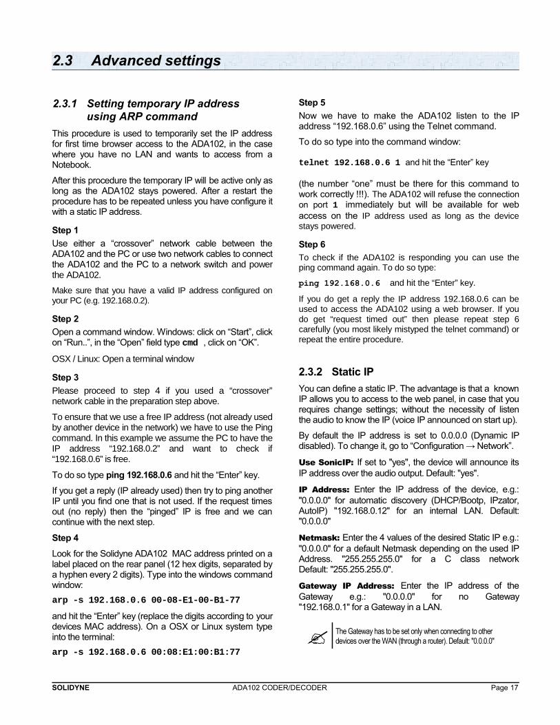
Step 7When the device is set as “Decoder”, it loads the defaultvalues for receive streaming, and usually you don't needto change this values (with the exception of port numbersand IP addresses). Next, the most important settings aredescripted.
Click on “Configuration → Streaming”
Step 8
In the field “Port” enter the same port number used inADA102 CODER. Hit “Apply” to confirm.
Step 9
At the decoder, you must to pay attention to the buffersize, which is the memory that holds the incomingstreaming audio to avoid drops. These interruptions occurwhen the bandwidth is insufficient for the transmitted audioquality and can be solved by increasing the buffer size.But note that larger buffer size will cause greater delaytime. The appropriate value depends on the bandwidth ofthe network and type of audio streaming.
Buffer size is expresed in miliseconds. For uncmpressedPCM streaming times of 40/80 mS works find. For codedformats larger times are nedded due to the times involvedin the decoding process (see “2.3.5 - About audiooptions”).
No other value must be defined. ADA102 automaticallyrecognize the incoming streaming. The audio quality isdefined in the CODER.
Emergency Pen Drive: Remember that you can connect anUSB device (Pen Drive) in the USB port. In case that thestreaming lost by network failure; ADA102 will play audio fromUSB device until the connection restores.
2.2.3 Status screen
Site type: Shows the working mode of the unit. In this casethe device woks as DECODER, located at the TransmitterPlant. It works as pasive receiver decoding the incomingstreaming from Studios (“Transmitter decoder” ).
Stream mode: Displays the current configured event tostart streaming to the remote destination(s).
Keep-alive: Displays the current configured keep-alivestrategy.
Connection status: Displays the actual connection state.
Incoming stream status: It shows the actual incomingstream status (ON/OFF).
Outgoing Sream: It shows the actual outgoing streamstatus (ON/OFF).
Audio input: selected input source (analogue or digital).
Audio Format: In a half-duplex link the audio format isdefined by the CODER. DECODER automatically detectthe incoming streaming format, showed in this field.
Input/Output audio level: Real level of audio signals,expressed in dBfs.
Relay 1..4: Shows the configured event for local relayswitch.
Remote inputs: State of the control inputs at the remotedevice (Studio). When an input is “on”, the correspondentgray box changes to green.
Local inputs: State of the inputs of local device.
Local Relays: State of local switches (which arecommanded by the remote device).
SOLIDYNE ADA102 CODER/DECODER Page 15

SOLIDYNE ADA102 CODER/DECODER Page 16
2.3 Advanced settings
2.3.1 Setting temporary IP address using ARP command
This procedure is used to temporarily set the IP addressfor first time browser access to the ADA102, in the casewhere you have no LAN and wants to access from aNotebook.
After this procedure the temporary IP will be active only aslong as the ADA102 stays powered. After a restart theprocedure has to be repeated unless you have configure itwith a static IP address.
Step 1
Use either a “crossover” network cable between theADA102 and the PC or use two network cables to connectthe ADA102 and the PC to a network switch and powerthe ADA102.
Make sure that you have a valid IP address configured onyour PC (e.g. 192.168.0.2).
Step 2
Open a command window. Windows: click on “Start”, clickon “Run..”, in the “Open” field type cmd , click on “OK”.
OSX / Linux: Open a terminal window
Step 3
Please proceed to step 4 if you used a “crossover”network cable in the preparation step above.
To ensure that we use a free IP address (not already usedby another device in the network) we have to use the Pingcommand. In this example we assume the PC to have theIP address “192.168.0.2” and want to check if“192.168.0.6” is free.
To do so type ping 192.168.0.6 and hit the “Enter” key.
If you get a reply (IP already used) then try to ping anotherIP until you find one that is not used. If the request timesout (no reply) then the “pinged” IP is free and we cancontinue with the next step.
Step 4
Look for the Solidyne ADA102 MAC address printed on alabel placed on the rear panel (12 hex digits, separated bya hyphen every 2 digits). Type into the windows commandwindow:
arp -s 192.168.0.6 00-08-E1-00-B1-77
and hit the “Enter” key (replace the digits according to yourdevices MAC address). On a OSX or Linux system typeinto the terminal:
arp -s 192.168.0.6 00:08:E1:00:B1:77
Step 5
Now we have to make the ADA102 listen to the IPaddress “192.168.0.6” using the Telnet command.
To do so type into the command window:
telnet 192.168.0.6 1 and hit the “Enter” key
(the number “one” must be there for this command towork correctly !!!). The ADA102 will refuse the connectionon port 1 immediately but will be available for webaccess on the IP address used as long as the devicestays powered.
Step 6
To check if the ADA102 is responding you can use theping command again. To do so type:
ping 192.168.0.6 and hit the “Enter” key.
If you do get a reply the IP address 192.168.0.6 can beused to access the ADA102 using a web browser. If youdo get “request timed out” then please repeat step 6carefully (you most likely mistyped the telnet command) orrepeat the entire procedure.
2.3.2 Static IP
You can define a static IP. The advantage is that a knownIP allows you to access to the web panel, in case that yourequires change settings; without the necessity of listenthe audio to know the IP (voice IP announced on start up).
By default the IP address is set to 0.0.0.0 (Dynamic IPdisabled). To change it, go to “Configuration → Network”.
Use SonicIP: If set to "yes", the device will announce itsIP address over the audio output. Default: "yes".
IP Address: Enter the IP address of the device, e.g.:"0.0.0.0" for automatic discovery (DHCP/Bootp, IPzator,AutoIP) "192.168.0.12" for an internal LAN. Default:"0.0.0.0"
Netmask: Enter the 4 values of the desired Static IP e.g.:"0.0.0.0" for a default Netmask depending on the used IPAddress. "255.255.255.0" for a C class networkDefault: "255.255.255.0".
Gateway IP Address: Enter the IP address of theGateway e.g.: "0.0.0.0" for no Gateway"192.168.0.1" for a Gateway in a LAN.
The Gateway has to be set only when connecting to other devices over the WAN (through a router). Default: "0.0.0.0"
SOLIDYNE ADA102 CODER/DECODER Page 17
Primary DNS: Enter the primary DNS IP address sothe device con connect to URLs (e.g. www.radio.com).Example: "195.186.0.1" Default: "0.0.0.0".
Alternative DNS: Enter the alternative DNS IPaddress in case the primary DNS is not reachable.Example: "195.186.4.111" Default: "0.0.0.0"
Syslog Address: Destination address for syslogmessages sent by the BCL program via the SYSLOGcommand. Set this to your syslog logging machine, ifyour syslog messages are recorded centrally.
If set to 0.0.0.0, syslog messages are broadcast.Default: "0.0.0.0"
DHCP Host Name: Name of the device sent in DHCPrequest. If left empty, a name based on the device'sMAC address is generated automatically. Enter up to 15Characters.
Web server port: Defines the port where thewebserver of the Solidyne device can be reached. If setto "0" the default HTTP port (80) is used.
2.3.3 Remote control
ADA102 has four electronic switches managed by theremote Solidyne device. Four inputs at the CODERmanages four switches in the DECODER, and viceversa. In addition, switches can be controlled by otherevents.
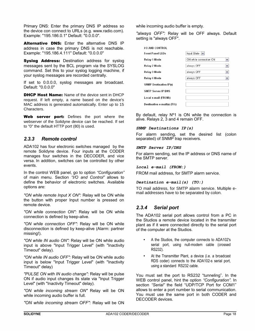
In the control WEB panel, go to option “Configuration”of main menu. Section “I/O and Control” allows todefine the behavior of electronic switches. Availableoptions are:
"ON while remote Input X ON": Relay will be ON whilethe button with proper Input number is pressed onremote device.
"ON while connection ON": Relay will be ON whileconnection is defined by keep-alive.
"ON while connection OFF": Relay will be ON whiledisconnection is defined by keep-alive (Alarm: partnermissing!).
"ON while IN audio ON": Relay will be ON while audioinput is above "Input Trigger Level" (with "InactivityTimeout" delay).
"ON while IN audio OFF": Relay will be ON while audioinput is below "Input Trigger Level" (with "InactivityTimeout" delay)
"PULSE ON with IN audio change": Relay will be pulseON if audio input changes its state via "Input TriggerLevel" (with "Inactivity Timeout" delay).
"ON while incoming stream ON" Relay will be ONwhile incoming audio buffer is full.
"ON while incoming stream OFF": Relay will be ON
while incoming audio buffer is empty.
"always OFF": Relay will be OFF always. Defaultsetting is "always OFF".
By default, relay Nº1 is ON while the connection isalive. Relays 2, 3 and 4 remain OFF.
SNMP Destinations IP(s)
For alarm sending, set the desired list (colonseparated) of SNMP trap receivers.
SMTP Server IP/DNS
For alarm sending, set the IP address or DNS name ofthe SMTP server.
Local e-mail (FROM:)
FROM mail address, for SMTP alarm service.
Destination e-mail(s) (TO:)
TO mail address, for SMTP alarm service. Multiple e-mail addresses have to be separated by colon.
2.3.4 Serial port
The ADA102 serial port allows control from a PC inthe Studios a remote device located in the transmiterplant as if it were connected directly to the serial portof the computer at the Studios.
• A the Studios, the computer connects to ADA102'sserial port, using null-modem cable (crossedRS232).
• At the Transmitter Plant, a device (i.e. a broadcastRDS coder) connects to the ADA102-s serial port,using a standard RS232 cable.
You must set the port to RS232 “tunneling”. In theWEB control panel, hint the option “Configuration”. Insection “Serial” the field “UDP/TCP Port for COM1”allows to enter a port number to serial communication.You must use the same port in both CODER andDECODER devices.
SOLIDYNE ADA102 CODER/DECODER Page 18
The option “Serial 2” is not implemented. Leave “UDP/TCP Control Port for COM2” as zero.
2.3.5 About audio settings
Encoding & FrequencyThe unit supports the following audio formats:
• MPEG1 / MPEG2 (solo half-duplex)• uLaw/aLaw• PCM MSB/LSB first
The passive receiver of a half-duplex systemautomatically recognizes the audio format but only foraudio formats with fixed content.
AES3 / S-PDIF input uses MPEG1 and the sample rate detects automatically (32, 44.1 o 48 KHz).
Remember: The playback buffer size is a veryimportant question. This value expresses the buffer sizein miliseconds. Smaller values minimize the delay, butincrease the chance of audio drops. The optimal valuedepends on audio format and sample rate.
MP3 baja tasa de bits 400 mS
MP3 alta tasa de bits 200 mS
PCM 44.1/48 KHz 40 mS
2.3.6 Calculating the bit rate
The final bit rate is the sum of the audio bit rate andencapsulation of audio packets make the networkprotocol used. For RTP the calculation is:
The Ethernet total overhead per packet is 300 bit.
The IP total overhead per packet is 160 bit.
The UDP total overhead per packet is 64 bit.
The RTP total overhead per packet is 128 bit (considering the enclousure MP3MPA into the usable RTP overhead, that have a extra header of 32 bit).
Total overhead of bits per packet =
Ethernet Overhead + IP Overhead + UDP Overhead + RTP Overhead = 652 bit
The audio bit rate expressed in bits/s, but the overheadis expressed in bits/packet. So we have to translate theoverhead (bit/packet) in overhead rate (bits/sec). Forthis we need to know the number of packets persecond, depending on the audio format. It can bemeasured with a software network protocol analyzersuch as the "Wireshark".
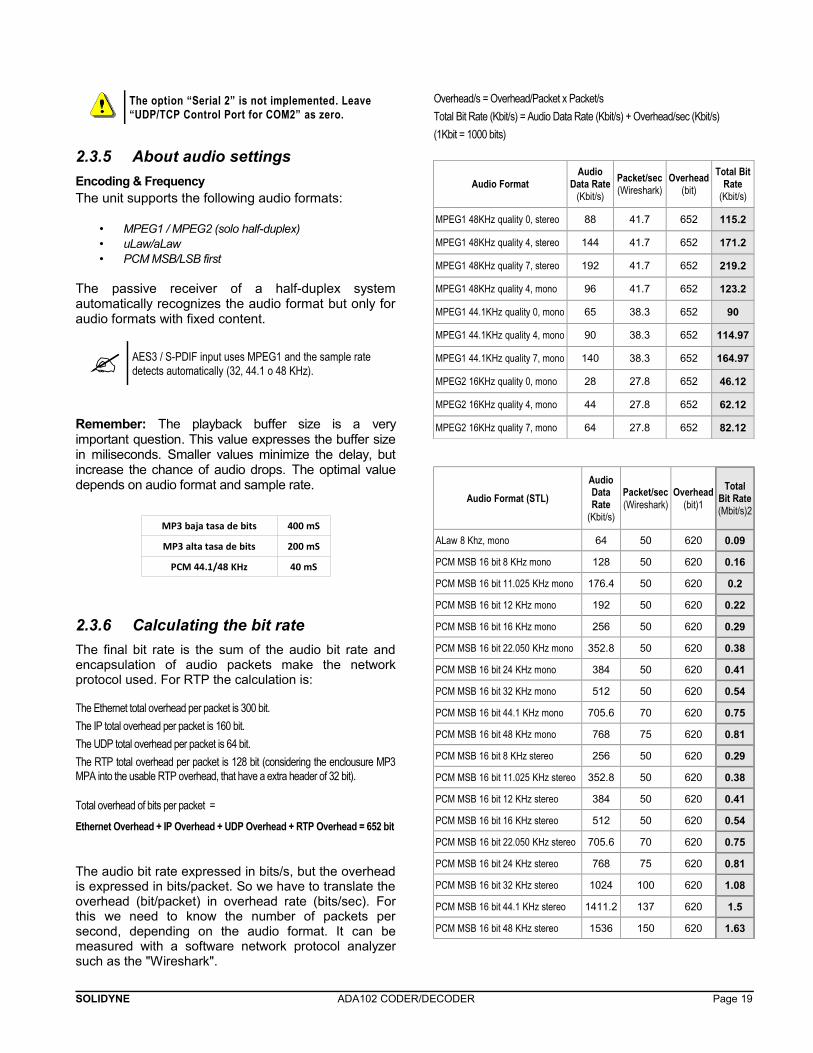
Overhead/s = Overhead/Packet x Packet/s
Total Bit Rate (Kbit/s) = Audio Data Rate (Kbit/s) + Overhead/sec (Kbit/s)
(1Kbit = 1000 bits)
Audio FormatAudio
Data Rate(Kbit/s)
Packet/sec(Wireshark)
Overhead(bit)
Total BitRate
(Kbit/s)
MPEG1 48KHz quality 0, stereo 88 41.7 652 115.2
MPEG1 48KHz quality 4, stereo 144 41.7 652 171.2
MPEG1 48KHz quality 7, stereo 192 41.7 652 219.2
MPEG1 48KHz quality 4, mono 96 41.7 652 123.2
MPEG1 44.1KHz quality 0, mono 65 38.3 652 90
MPEG1 44.1KHz quality 4, mono 90 38.3 652 114.97
MPEG1 44.1KHz quality 7, mono 140 38.3 652 164.97
MPEG2 16KHz quality 0, mono 28 27.8 652 46.12
MPEG2 16KHz quality 4, mono 44 27.8 652 62.12
MPEG2 16KHz quality 7, mono 64 27.8 652 82.12
Audio Format (STL)
AudioDataRate
(Kbit/s)
Packet/sec(Wireshark)
Overhead(bit)1
TotalBit Rate(Mbit/s)2
ALaw 8 Khz, mono 64 50 620 0.09
PCM MSB 16 bit 8 KHz mono 128 50 620 0.16
PCM MSB 16 bit 11.025 KHz mono 176.4 50 620 0.2
PCM MSB 16 bit 12 KHz mono 192 50 620 0.22
PCM MSB 16 bit 16 KHz mono 256 50 620 0.29
PCM MSB 16 bit 22.050 KHz mono 352.8 50 620 0.38
PCM MSB 16 bit 24 KHz mono 384 50 620 0.41
PCM MSB 16 bit 32 KHz mono 512 50 620 0.54
PCM MSB 16 bit 44.1 KHz mono 705.6 70 620 0.75
PCM MSB 16 bit 48 KHz mono 768 75 620 0.81
PCM MSB 16 bit 8 KHz stereo 256 50 620 0.29
PCM MSB 16 bit 11.025 KHz stereo 352.8 50 620 0.38
PCM MSB 16 bit 12 KHz stereo 384 50 620 0.41
PCM MSB 16 bit 16 KHz stereo 512 50 620 0.54
PCM MSB 16 bit 22.050 KHz stereo 705.6 70 620 0.75
PCM MSB 16 bit 24 KHz stereo 768 75 620 0.81
PCM MSB 16 bit 32 KHz stereo 1024 100 620 1.08
PCM MSB 16 bit 44.1 KHz stereo 1411.2 137 620 1.5
PCM MSB 16 bit 48 KHz stereo 1536 150 620 1.63
SOLIDYNE ADA102 CODER/DECODER Page 19
2.3.7 Emergency pendrive
ADA102 only recognizes files with extension “.mp3”.USB drive must contain the audio files placed directly inthe root folder, and a playlist file named playlist.m3u,which determines the order in which files are played.
The playlist can be created manually using a simpletext editor (eg Windows Notepad) and then changingthe file extension from .txt to .m3u. Here's an example:
# sample playlist begin audio1.mp3audio2.mp3audio3.mp3audio4.mp3# sample playlist end
As files are in the root folder, it is not necessary toindicate the path. Lines preceded by pound (#) arecomments.
The playlist can also be created using the audio playerWinamp (www.winamp.com) or any other audio playerto generate playlists in .m3u. Usually create an .m3uonly requires to save the list of songs loaded on theplayer, as a playlist file type .m3u.
Supported USB memory drives are detailed in “1.2.4 – USB port”
SOLIDYNE ADA102 CODER/DECODER Page 20
2.4 Other connection modes
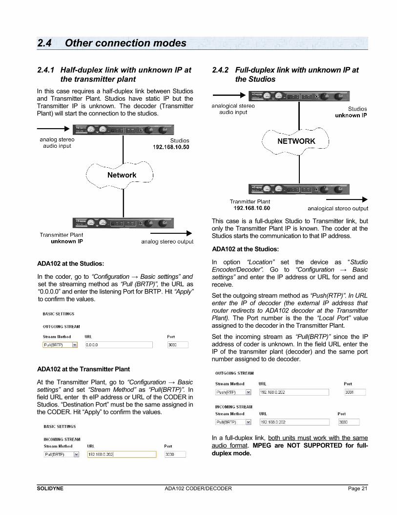
2.4.1 Half-duplex link with unknown IP atthe transmitter plant
In this case requires a half-duplex link between Studiosand Transmitter Plant. Studios have static IP but theTransmitter IP is unknown. The decoder (TransmitterPlant) will start the connection to the studios.
ADA102 at the Studios:
In the coder, go to “Configuration → Basic settings” andset the streaming method as “Pull (BRTP)”, the URL as“0.0.0.0” and enter the listening Port for BRTP. Hit “Apply”to confirm the values.
ADA102 at the Transmitter Plant
At the Transmitter Plant, go to “Configuration → Basicsettings” and set “Stream Method” as “Pull(BRTP)”. Infield URL enter th eIP address or URL of the CODER inStudios. “Destination Port” must be the same assigned inthe CODER. Hit “Apply” to confirm the values.
2.4.2 Full-duplex link with unknown IP at the Studios
This case is a full-duplex Studio to Transmitter link, butonly the Transmitter Plant IP is known. The coder at theStudios starts the communication to that IP address.
ADA102 at the Studios:
In option “Location” set the device as “StudioEncoder/Decoder”. Go to “Configuration → Basicsettings” and enter the IP address or URL for send andreceive.
Set the outgoing stream method as “Push(RTP)”. In URLenter the IP of decoder (the external IP address thatrouter redirects to ADA102 decoder at the TransmitterPlant). The Port number is the the “Local Port” valueassigned to the decoder in the Transmitter Plant.
Set the incoming stream as “Pull(BRTP)” since the IPaddress of coder is unknown. In the field URL enter theIP of the transmiter plant (decoder) and the same portnumber assigned to de decoder.
In a full-duplex link, both units must work with the sameaudio format. MPEG are NOT SUPPORTED for full-duplex mode.
SOLIDYNE ADA102 CODER/DECODER Page 21
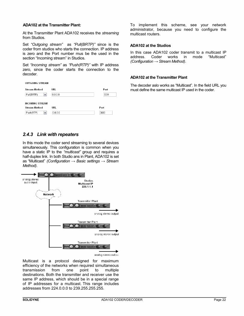
ADA102 at the Transmitter Plant:
At the Transmitter Plant ADA102 receives the streamingfrom Studios.
Set “Outgoing stream” as “Pull(BRTP)” since is thecoder from studios who starts the connection. IP addressis zero and the Port number mus be the used in thesection “Incoming stream” in Studios.
Set “Incoming stream” as “Push(RTP)” with IP addresszero, since the coder starts the connection to thedecoder.
2.4.3 Link with repeaters
In this mode the coder send streaming to several devicessimultaneously. This configuration is common when youhave a static IP to the “multicast” group and requires ahalf-duplex link. In both Studio ans in Plant, ADA102 is setas “Multicast” (Configuration → Basic settings → StreamMethod).
Multicast is a protocol designed for maximumefficiency of the networks when required simultaneoustransmission from one point to multipledestinations. Both the transmitter and receiver use thesame IP address, which should be in a special rangeof IP addresses for a multicast. This range includesaddresses from 224.0.0.0 to 239.255.255.255.
To implement this scheme, see your networkadministrator, because you need to configure themulticast routers.
ADA102 at the Studios
In this case ADA102 coder transmit to a multicast IPaddress. Coder works in mode “Multicast”(Configuration → Stream Method).
ADA102 at the Transmitter Plant
The decoder aslo works as “Multicast”. In the field URL youmust define the same multicast IP used in the coder.
SOLIDYNE ADA102 CODER/DECODER Page 22
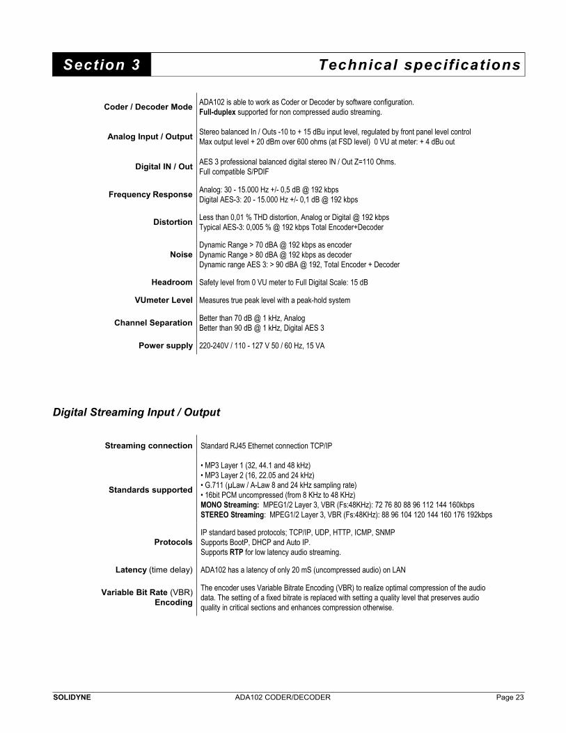
Section 3 Technical specifications
Coder / Decoder ModeADA102 is able to work as Coder or Decoder by software configuration.Full-duplex supported for non compressed audio streaming.
Analog Input / OutputStereo balanced In / Outs -10 to + 15 dBu input level, regulated by front panel level controlMax output level + 20 dBm over 600 ohms (at FSD level) 0 VU at meter: + 4 dBu out
Digital IN / OutAES 3 professional balanced digital stereo IN / Out Z=110 Ohms.Full compatible S/PDIF
Frequency ResponseAnalog: 30 - 15.000 Hz +/- 0,5 dB @ 192 kbpsDigital AES-3: 20 - 15.000 Hz +/- 0,1 dB @ 192 kbps
DistortionLess than 0,01 % THD distortion, Analog or Digital @ 192 kbpsTypical AES-3: 0,005 % @ 192 kbps Total Encoder+Decoder
NoiseDynamic Range > 70 dBA @ 192 kbps as encoderDynamic Range > 80 dBA @ 192 kbps as decoderDynamic range AES 3: > 90 dBA @ 192, Total Encoder + Decoder
Headroom Safety level from 0 VU meter to Full Digital Scale: 15 dB
VUmeter Level Measures true peak level with a peak-hold system
Channel SeparationBetter than 70 dB @ 1 kHz, AnalogBetter than 90 dB @ 1 kHz, Digital AES 3
Power supply 220-240V / 110 - 127 V 50 / 60 Hz, 15 VA
Digital Streaming Input / Output
Streaming connection Standard RJ45 Ethernet connection TCP/IP
Standards supported
• MP3 Layer 1 (32, 44.1 and 48 kHz)• MP3 Layer 2 (16, 22.05 and 24 kHz)• G.711 (µLaw / A-Law 8 and 24 kHz sampling rate)• 16bit PCM uncompressed (from 8 KHz to 48 KHz)MONO Streaming: MPEG1/2 Layer 3, VBR (Fs:48KHz): 72 76 80 88 96 112 144 160kbpsSTEREO Streaming: MPEG1/2 Layer 3, VBR (Fs:48KHz): 88 96 104 120 144 160 176 192kbps
ProtocolsIP standard based protocols; TCP/IP, UDP, HTTP, ICMP, SNMPSupports BootP, DHCP and Auto IP. Supports RTP for low latency audio streaming.
Latency (time delay) ADA102 has a latency of only 20 mS (uncompressed audio) on LAN
Variable Bit Rate (VBR)Encoding
The encoder uses Variable Bitrate Encoding (VBR) to realize optimal compression of the audio data. The setting of a fixed bitrate is replaced with setting a quality level that preserves audio quality in critical sections and enhances compression otherwise.
SOLIDYNE ADA102 CODER/DECODER Page 23
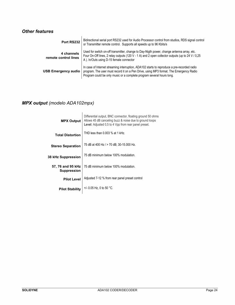
Other features
Port RS232Bidirectional serial port RS232 used for Audio Processor control from studios, RDS signal controlor Transmitter remote control. Supports all speeds up to 96 Kbits/s
4 channels remote control lines
Used for switch on-off transmitter, change to Day-Nigth power, change antenna array, etc.Four On-Off lines, 2 relay outputs (120 V - 1 A) and 2 open collector outputs (up to 24 V / 0,25 A ). In/Outs using D-15 female connector
USB Emergency audioIn case of Internet streaming interruption, ADA102 starts to reproduce a pre-recorded radio program. The user must record it on a Pen Drive, using MP3 format. The Emergency Radio Program could be only music or a complete program several hours long.
MPX output (modelo ADA102mpx)
MPX OutputDifferential output, BNC connector, floating ground 50 ohmsAllows 45 dB canceling buzz & noise due to ground loopsLevel: Adjusted 0,5 to 4 Vpp from rear panel preset.
Total DistortionTHD less than 0.003 % at 1 kHz.
Stereo Separation 75 dB at 400 Hz / > 70 dB; 30-15.000 Hz.
38 kHz Suppression 75 dB minimum below 100% modulation.
57, 76 and 95 kHzSuppression
75 dB minimum below 100% modulation.
Pilot Level Adjusted 7-12 % from rear panel preset control
Pilot Stability +/- 0.05 Hz, 0 to 50 °C.
SOLIDYNE ADA102 CODER/DECODER Page 24