Embed Size (px)
Citation preview

Page 2 Audimax 362HD SOLIDYNE
Table of contents
What’s in the box?..........................................4
Generalities.....................................................4
Chapter 1 – Installation.......................5
1.1 Power source............................................5
1.2 Rear panel - wiring....................................51.2.1 RJ-45............................................................5
1.2.2 USB input/output........................................6
1.3 Modo HD (High Definition).......................6
1.4 MPX Output..............................................61.4.1 Humming.....................................................7
1.4.2 Modulation level..........................................7
1.5 ADITIONAL TECHNICAL INFORMATIONBalanced and unbalanced I/O.........................7
1.5.1 Balancead lines............................................7
1.5.2 Unbalanced lines.........................................7
1.5.3 Diagrama de conexión a tierrarecomendado...........................................................8
1.6 Work settings............................................81.6.1 Processor as FM stereo coder.....................81.6.1.1 USB for external streaming..............................81.6.2 Retransmission of incoming streaming.......9
1.6.3 As audio processor....................................10
Chapter 2 Using the processor..........11
2.1 MPX level................................................11
2.2 Audio settings.........................................112.2.1 Input level..................................................11
2.2.2 Customizing the sound..............................11
Chapter 3 Theory of audio processors....13
3.1 A brief story............................................13
3.2 Audimax 362HDHD overview..................143.2.1 Introduction...............................................14
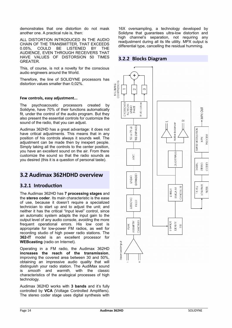
3.2.2 Blocks Diagram..........................................14
3.2.3 PROCESSING STAGES...........................15Stage 1: Peak Asymmetry Canceller...................15
Stage 2: Input Expander.....................................15
Stage 3: Level Input Control...............................16
Stage 4: Multiband Compressors.......................16
Stage 5: Dynamic Equalizer................................16
Stage 6: Energy Bands........................................17
Stage 7: Stereo Coder.........................................17
MPX processing..................................................17
Chapter 4 – Technical Specifications..19
SOLIDYNE Audimax 362HD Page 3
Ultima revisón14 de Enero de 2016
What’s in the box?The Audimax 362HD packaging include:
1 Audimax 362HD Processor (include supports for rack montage). 1 User’s manual. 1 Power cord. 1 Guarantee agreement. 4 self-adhesive rubber supports.
GeneralitiesPlease read carefully the following recommendations:
o Audimax 362HD processors are designed for rack montage in 19” standard racks. Also it can be usedon a table or desktop, quitting the lateral supports.
o The room temperature must be between 5 and 40°C (41°/104° F). Avoid the direct solar ray incidenceon the equipment. Avoid the proximity of heat sources and high electromagnetic fields (high powertransformers, motors, etc). 462-MKII have internal protection against RF fields, that allows assembly itnext to AM/FM RF amplifiers.
o The installation in very humid places or with saline atmosphere will have to be avoided, since they willcan cause corrosion in the printed circuit board and electronic component.
Page 4 Audimax 362HD SOLIDYNE
Chapter 1 Chapter 1 – Installation– Installation
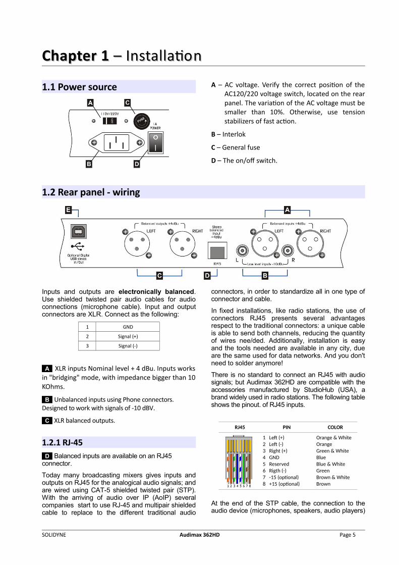
1.1 Power source A – AC voltage. Verify the correct position of theAC120/220 voltage switch, located on the rearpanel. The variation of the AC voltage must besmaller than 10%. Otherwise, use tensionstabilizers of fast action.
B – Interlok
C – General fuse
D – The on/off switch.
1.2 Rear panel - wiring
Inputs and outputs are electronically balanced.Use shielded twisted pair audio cables for audioconnections (microphone cable). Input and outputconnectors are XLR. Connect as the following:
1 GND
2 Signal (+)
3 Signal (-)
A XLR inputs Nominal level + 4 dBu. Inputs worksin "bridging" mode, with impedance bigger than 10KOhms.
B Unbalanced inputs using Phone connectors. Designed to work with signals of -10 dBV.
C XLR balanced outputs.
1.2.1 RJ-45 D Balanced inputs are available on an RJ45 connector.
Today many broadcasting mixers gives inputs andoutputs on RJ45 for the analogical audio signals; andare wired using CAT-5 shielded twisted pair (STP).With the arriving of audio over IP (AoIP) severalcompanies start to use RJ-45 and multipair shieldedcable to replace to the different traditional audio
connectors, in order to standardize all in one type ofconnector and cable.
In fixed installations, like radio stations, the use ofconnectors RJ45 presents several advantagesrespect to the traditional connectors: a unique cableis able to send both channels, reducing the quantityof wires nee/ded. Additionally, installation is easyand the tools needed are available in any city, dueare the same used for data networks. And you don'tneed to solder anymore!
There is no standard to connect an RJ45 with audiosignals; but Audimax 362HD are compatible with theaccessories manufactured by StudioHub (USA), abrand widely used in radio stations. The following tableshows the pinout. of RJ45 inputs.
RJ45 PIN COLOR
1 Left (+)2 Left (-) 3 Right (+)4 GND5 Reserved6 Rigth (-) 7 -15 (optional)8 +15 (optional)
Orange & WhiteOrangeGreen & WhiteBlueBlue & WhiteGreenBrown & WhiteBrown
At the end of the STP cable, the connection to theaudio device (microphones, speakers, audio players)
SOLIDYNE Audimax 362HD Page 5
needs standard audio connectors. The RJ45 wiringoffers short end cable with female RJ45 to anystandard audio connector. Please refer to web sitefor more info.
1.2.2 USB input/output E Audimax 362 HD / USB has an optionalmodule that enables receiving and sending audioconnected to a computer with a USB A/B standardcable.
Connect the unit to any USB port of a computerrunning Windows©. When connecting, Windows©recognizes the USB device and install the drivers.Additional drivers are not required. Audimax 362HDwill appear on Windows like one stereo USB audiodevice and one stereo USB recording device.
To check the available sound devices, go to“Windows Control Panel > Sound devices > Audio”.Here the default sound devices are defined.Remember to update the settings on the audioapplications.
ABOUT USB DETECTION
Before connecting the USB cable to the computer, make sure that both the console and the computer have an effective ground by power cords. For safety, connect a tester in the range of 25VAC between the chassis of the PC and console and verify that the voltage is zero. Only then connect the USB. If there are differencesof tension, the USB port on the console or the computer may resultdamaged.
We recommend do not change the USB cable to other USB ports, to avoid that Windows change the order of USB devices.
Windows 7 / 8.1,: Check that the audio recording device was properly recognized. If Windows 7 recognized it as "microphone device", the recordings will be mono (the same signal in both channels). To correct this: Control Panel → Sound → Record → choose the USB device (shown as USB microphone) and click [Properties]. Then select the tab "Advanced", display the menu of formatting options and choose a format for stereo recording (2 channels, 16 bits, 44100Hz).
1.3 Modo HD (High Definition)HD mode is suitable for audio applications wherethe stage FM stereo coding (MPX) is not used. It isan important contribution to the technology as audioprocessors can be used in digital radio (HD Radio)or conventional radios inside the Recording Studioto record voices. It is also suitable for small AMradio stations.
The main feature of "HD mode" is that the pre-emphasis (75/50 microseconds) is disabled,achieving a brighter treble and rich sound. Thisenables the processor to be used in soundreinforcement installations (small rooms,
auditoriums) in popular music concerts, discos,sound systems in malls, etc.
In HD mode, the processor connects using theaudio outputs (balanced or USB).
When the unit is set to HD mode:
• Pre-emphasis for FM is disabled (and therefore de-emphasis on audio outputs is disabled).
• A fast limiter is enabled over the audio outputs.• The MPX output turns of.
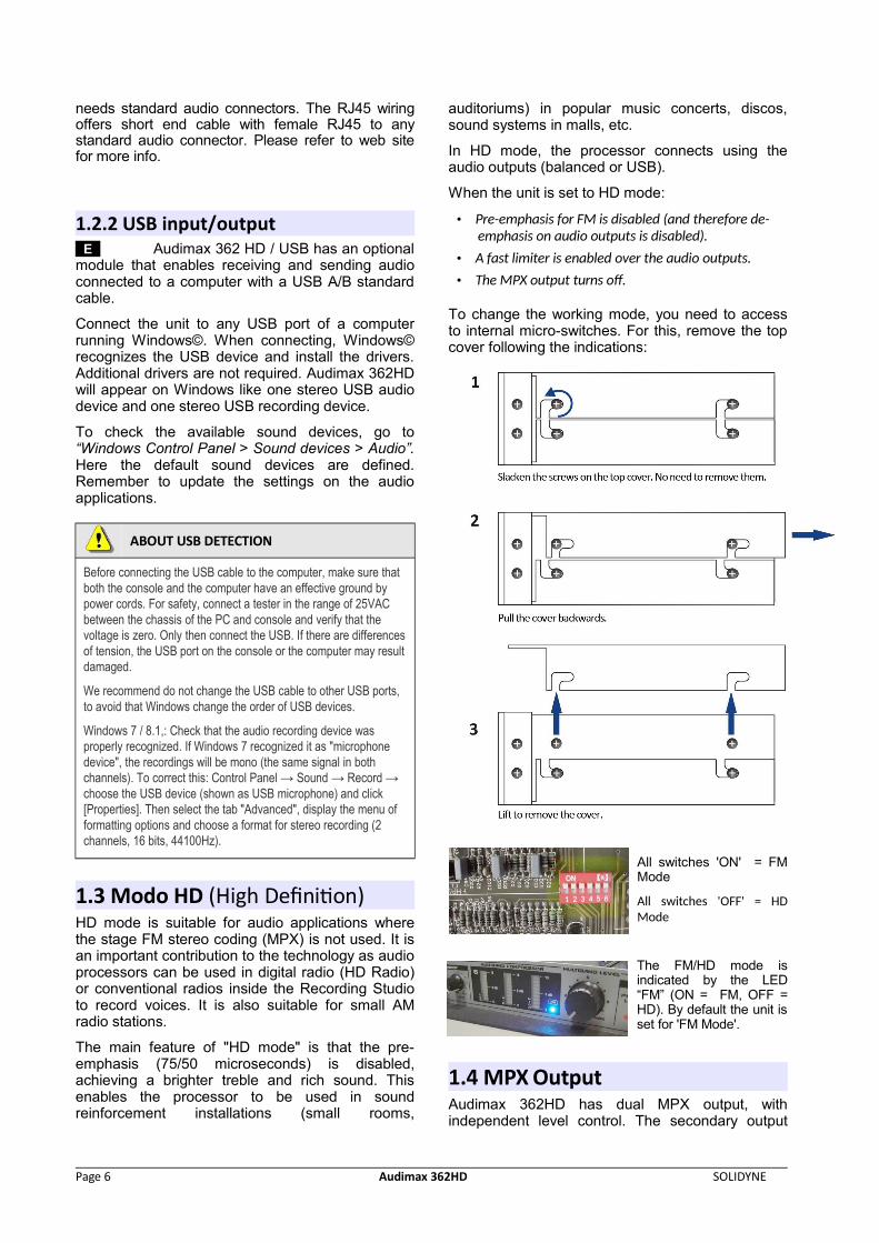
To change the working mode, you need to accessto internal micro-switches. For this, remove the topcover following the indications:
All switches 'ON' = FMMode
All switches 'OFF' = HDMode
The FM/HD mode isindicated by the LED“FM” (ON = FM, OFF =HD). By default the unit isset for 'FM Mode'.
1.4 MPX OutputAudimax 362HD has dual MPX output, withindependent level control. The secondary output
Page 6 Audimax 362HD SOLIDYNE
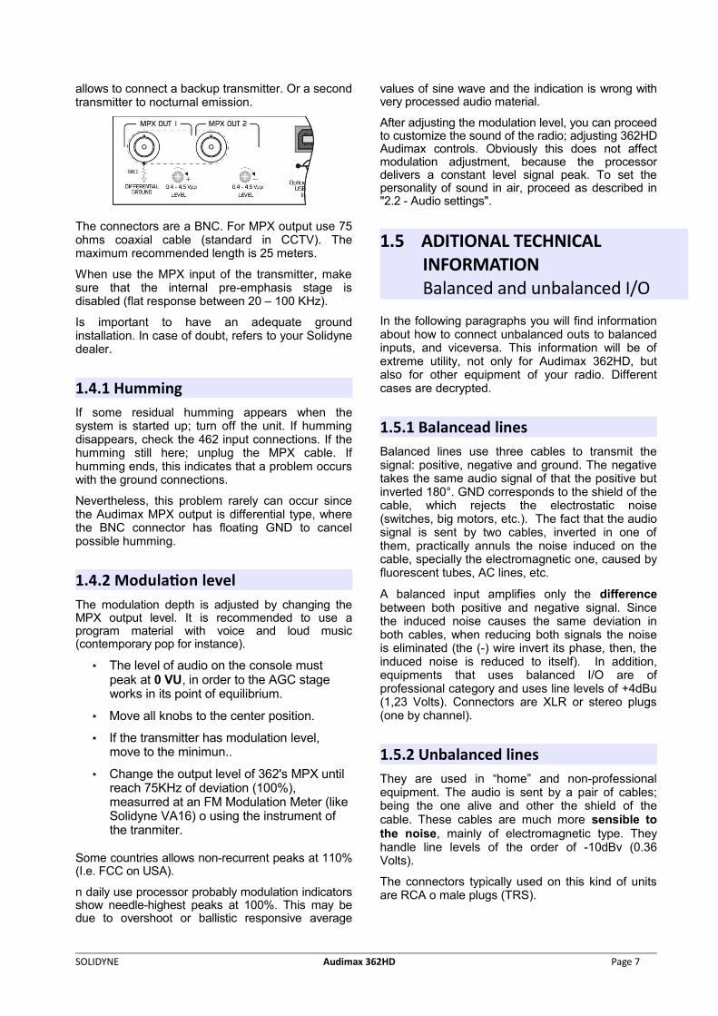
allows to connect a backup transmitter. Or a secondtransmitter to nocturnal emission.
The connectors are a BNC. For MPX output use 75ohms coaxial cable (standard in CCTV). Themaximum recommended length is 25 meters.
When use the MPX input of the transmitter, makesure that the internal pre-emphasis stage isdisabled (flat response between 20 – 100 KHz).
Is important to have an adequate groundinstallation. In case of doubt, refers to your Solidynedealer.
1.4.1 HummingIf some residual humming appears when thesystem is started up; turn off the unit. If hummingdisappears, check the 462 input connections. If thehumming still here; unplug the MPX cable. Ifhumming ends, this indicates that a problem occurswith the ground connections.
Nevertheless, this problem rarely can occur sincethe Audimax MPX output is differential type, wherethe BNC connector has floating GND to cancelpossible humming.
1.4.2 Modulation levelThe modulation depth is adjusted by changing theMPX output level. It is recommended to use aprogram material with voice and loud music(contemporary pop for instance).
• The level of audio on the console must peak at 0 VU, in order to the AGC stage works in its point of equilibrium.
• Move all knobs to the center position.
• If the transmitter has modulation level, move to the minimun..
• Change the output level of 362's MPX until reach 75KHz of deviation (100%), measurred at an FM Modulation Meter (like Solidyne VA16) o using the instrument of the tranmiter.
Some countries allows non-recurrent peaks at 110%(I.e. FCC on USA).
n daily use processor probably modulation indicatorsshow needle-highest peaks at 100%. This may bedue to overshoot or ballistic responsive average
values of sine wave and the indication is wrong withvery processed audio material.
After adjusting the modulation level, you can proceedto customize the sound of the radio; adjusting 362HDAudimax controls. Obviously this does not affectmodulation adjustment, because the processordelivers a constant level signal peak. To set thepersonality of sound in air, proceed as described in"2.2 - Audio settings".
1.5 ADITIONAL TECHNICAL INFORMATIONBalanced and unbalanced I/O
In the following paragraphs you will find informationabout how to connect unbalanced outs to balancedinputs, and viceversa. This information will be ofextreme utility, not only for Audimax 362HD, butalso for other equipment of your radio. Differentcases are decrypted.
1.5.1 Balancead linesBalanced lines use three cables to transmit thesignal: positive, negative and ground. The negativetakes the same audio signal of that the positive butinverted 180°. GND corresponds to the shield of thecable, which rejects the electrostatic noise(switches, big motors, etc.). The fact that the audiosignal is sent by two cables, inverted in one ofthem, practically annuls the noise induced on thecable, specially the electromagnetic one, caused byfluorescent tubes, AC lines, etc.
A balanced input amplifies only the differencebetween both positive and negative signal. Sincethe induced noise causes the same deviation inboth cables, when reducing both signals the noiseis eliminated (the (-) wire invert its phase, then, theinduced noise is reduced to itself). In addition,equipments that uses balanced I/O are ofprofessional category and uses line levels of +4dBu(1,23 Volts). Connectors are XLR or stereo plugs(one by channel).
1.5.2 Unbalanced linesThey are used in “home” and non-professionalequipment. The audio is sent by a pair of cables;being the one alive and other the shield of thecable. These cables are much more sensible tothe noise, mainly of electromagnetic type. Theyhandle line levels of the order of -10dBv (0.36Volts).
The connectors typically used on this kind of unitsare RCA o male plugs (TRS).
SOLIDYNE Audimax 362HD Page 7
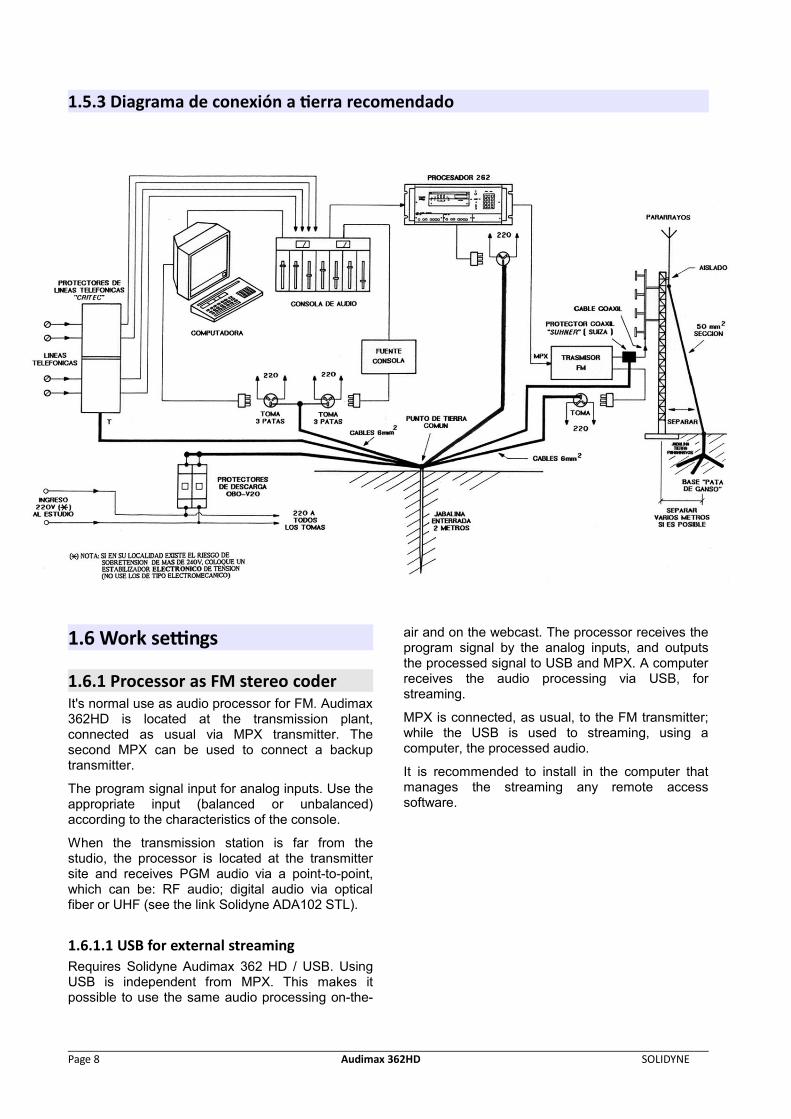
1.5.3 Diagrama de conexión a tierra recomendado
1.6 Work settings
1.6.1 Processor as FM stereo coder It's normal use as audio processor for FM. Audimax362HD is located at the transmission plant,connected as usual via MPX transmitter. Thesecond MPX can be used to connect a backuptransmitter.
The program signal input for analog inputs. Use theappropriate input (balanced or unbalanced)according to the characteristics of the console.
When the transmission station is far from thestudio, the processor is located at the transmittersite and receives PGM audio via a point-to-point,which can be: RF audio; digital audio via opticalfiber or UHF (see the link Solidyne ADA102 STL).
1.6.1.1 USB for external streaming Requires Solidyne Audimax 362 HD / USB. UsingUSB is independent from MPX. This makes itpossible to use the same audio processing on-the-
air and on the webcast. The processor receives theprogram signal by the analog inputs, and outputsthe processed signal to USB and MPX. A computerreceives the audio processing via USB, forstreaming.
MPX is connected, as usual, to the FM transmitter;while the USB is used to streaming, using acomputer, the processed audio.
It is recommended to install in the computer thatmanages the streaming any remote accesssoftware.
Page 8 Audimax 362HD SOLIDYNE
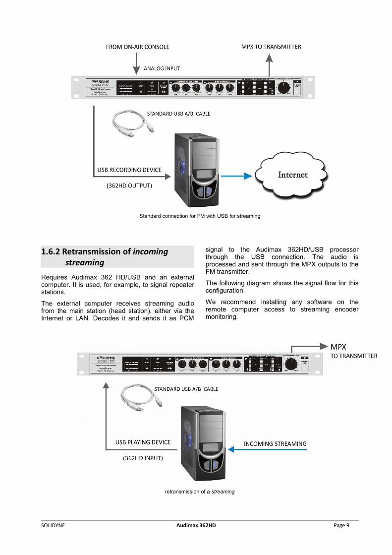
Standard connection for FM with USB for streaming
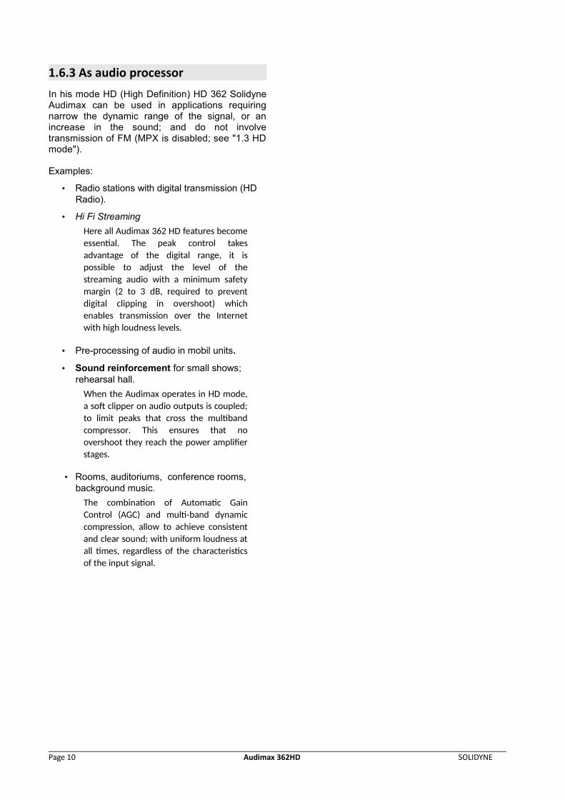
1.6.2 Retransmission of incoming streaming
Requires Audimax 362 HD/USB and an externalcomputer. It is used, for example, to signal repeaterstations.
The external computer receives streaming audiofrom the main station (head station), either via theInternet or LAN. Decodes it and sends it as PCM
signal to the Audimax 362HD/USB processorthrough the USB connection. The audio isprocessed and sent through the MPX outputs to theFM transmitter.
The following diagram shows the signal flow for thisconfiguration.
We recommend installing any software on theremote computer access to streaming encodermonitoring.
retransmission of a streaming
SOLIDYNE Audimax 362HD Page 9
1.6.3 As audio processor
In his mode HD (High Definition) HD 362 SolidyneAudimax can be used in applications requiringnarrow the dynamic range of the signal, or anincrease in the sound; and do not involvetransmission of FM (MPX is disabled; see "1.3 HDmode").
Examples:
• Radio stations with digital transmission (HD Radio).
• Hi Fi Streaming
Here all Audimax 362 HD features becomeessential. The peak control takesadvantage of the digital range, it ispossible to adjust the level of thestreaming audio with a minimum safetymargin (2 to 3 dB, required to preventdigital clipping in overshoot) whichenables transmission over the Internetwith high loudness levels.
• Pre-processing of audio in mobil units.
• Sound reinforcement for small shows; rehearsal hall.
When the Audimax operates in HD mode,a soft clipper on audio outputs is coupled;to limit peaks that cross the multibandcompressor. This ensures that noovershoot they reach the power amplifierstages.
• Rooms, auditoriums, conference rooms, background music.
The combination of Automatic GainControl (AGC) and multi-band dynamiccompression, allow to achieve consistentand clear sound; with uniform loudness atall times, regardless of the characteristicsof the input signal.
Page 10 Audimax 362HD SOLIDYNE
Chapter 2 Chapter 2 Using the processorUsing the processor
2.1 MPX levelThe first adjustment is the modulation level on thetransmitter (please see “1.4.2 – Modulation level”).
2.2 Audio settingsAudimax 362HD was designed to offers an easyand very intuitive operation. You don’t need to havespecialized knowledge to start up the processor andto adjust the sound settings. Simply begins placingall knobs to the center position. That is all! You willbe on-air with a great sound. Soon you will have tocustomise the sound according to the musical styleof your radio, for which we recommends you to readthe following explanations kindly.
2.2.1 Input levelAudimax 362HD has an automated control for theinput level. The rear panel presents balanced inputs(+4dBu) and unbalanced inputs (-10 dBV). Makesure to connect the mixing console to the appropriateinputs according its nominal output level.
Automatic input gain control (AGC) eliminatesvariations in characteristics of the operation of themixing console level, and compensates fordifferences in level of the recorded material. That is,if the level from the console remains very low forsome time, the processor will compensate its inputto maintain a constant output level. If the outputlevel of the console exceeds constantly 0VU; AGCattenuate the signal. In this way the program signalreaches the processing steps with constant leveland sound on-the-air is consistent, always with thesame degree of processing.
To verify that the input level is appropriate, observingthe three LEDs on the AGC, located on the front paneloperate properly: The first LED (green) should bealways on in the presence of music or voice; thesecond (yellow) flashing audio peaks or always on.The third LED (red) should never be turned onpermanently.
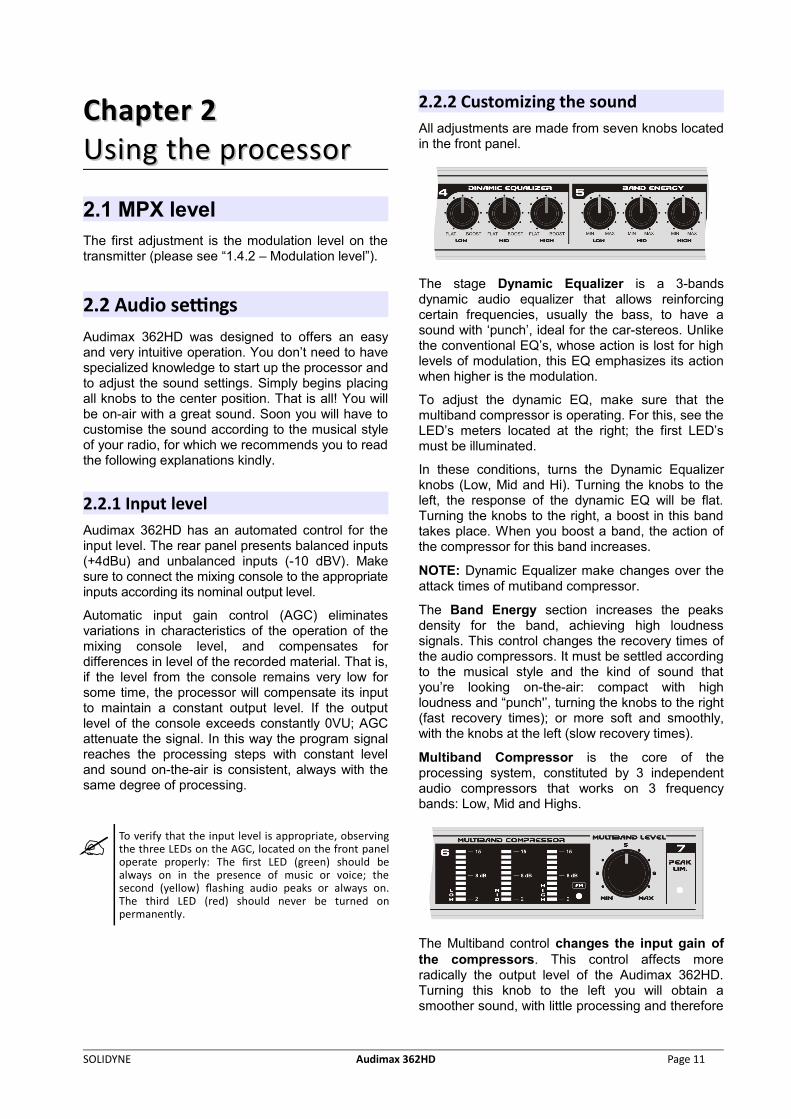
2.2.2 Customizing the soundAll adjustments are made from seven knobs locatedin the front panel.
The stage Dynamic Equalizer is a 3-bandsdynamic audio equalizer that allows reinforcingcertain frequencies, usually the bass, to have asound with ‘punch’, ideal for the car-stereos. Unlikethe conventional EQ’s, whose action is lost for highlevels of modulation, this EQ emphasizes its actionwhen higher is the modulation.
To adjust the dynamic EQ, make sure that themultiband compressor is operating. For this, see theLED’s meters located at the right; the first LED’smust be illuminated.
In these conditions, turns the Dynamic Equalizerknobs (Low, Mid and Hi). Turning the knobs to theleft, the response of the dynamic EQ will be flat.Turning the knobs to the right, a boost in this bandtakes place. When you boost a band, the action ofthe compressor for this band increases.
NOTE: Dynamic Equalizer make changes over theattack times of mutiband compressor.
The Band Energy section increases the peaksdensity for the band, achieving high loudnesssignals. This control changes the recovery times ofthe audio compressors. It must be settled accordingto the musical style and the kind of sound thatyou’re looking on-the-air: compact with highloudness and “punch'’, turning the knobs to the right(fast recovery times); or more soft and smoothly,with the knobs at the left (slow recovery times).
Multiband Compressor is the core of theprocessing system, constituted by 3 independentaudio compressors that works on 3 frequencybands: Low, Mid and Highs.
The Multiband control changes the input gain ofthe compressors. This control affects moreradically the output level of the Audimax 362HD.Turning this knob to the left you will obtain asmoother sound, with little processing and therefore
SOLIDYNE Audimax 362HD Page 11
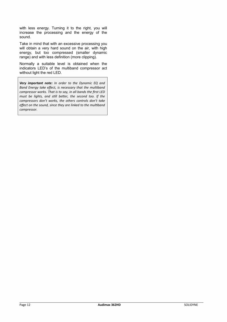
with less energy. Turning it to the right, you willincrease the processing and the energy of thesound.
Take in mind that with an excessive processing youwill obtain a very hard sound on the air, with highenergy, but too compressed (smaller dynamicrange) and with less definition (more clipping).
Normally a suitable level is obtained when theindicators LED’s of the multiband compressor actwithout light the red LED.
Very important note: In order to the Dynamic EQ andBand Energy take effect, is necessary that the multibandcompressor works. That is to say, in all bands the first LEDmust be lights, and still better, the second too. If thecompressors don’t works, the others controls don’t takeeffect on the sound, since they are linked to the multibandcompressor.
Page 12 Audimax 362HD SOLIDYNE
Chapter 3Chapter 3Theory of audio Theory of audio processorsprocessors
NOTE: in order to complement the study of this subject isrecommended to visit our WEB (www.solidynepro.com). Inthe DEMO section there are a Power Point presentationcalled Audio Processors. It has a complete TechnicalAppendix that it analyzes how the audio processingincreases the coverage area of the FM stereo transmission.
3.1 A brief story...From mid of the 1930 decade, when appears thefirst compressors and expanders units, to thepresent time, all chains of audio for broadcastingincorporate devices whose function is to alter thedynamic range of the sound. The advance of thetechnology improves these devices during the ‘70s.
The compressors, expanders and audio limiterswere gaining in efficiency and complexity. In thebeginning, its main parameters (attack and recoverytimes, thresholds, etc.) were fixed by design or bythe operator, through the device’s controls. In the'70s, these functions begin to be automatic, basedon the characteristics of the audio signal, but havingat the same time a control on their action to be ableto customize the sound.
When five or more devices are grouped in a sameequipment, they begin to be denominated: AUDIOPROCESSORS.
Since 1970, Solidyne introduces importantadvances in this field, like the invention of a controltechnique based on FET’s with guided gate (seepublication in Rev. Tel. Electrónica, September/70).They follow diverse publications, having particularinternational relevance the work published inJune/76 at the Journal of the Audio EngineeringSociety, New York, U.S.A. where a new conceptwas introduced, which persist to the present time:PHSICOACUSTIC PROCESSING.
This new technique is the base for all the modernaudio processors for broadcasting use. Thenecessity to process the phase to makesymmetrical the human voice waveform is anotherone of the techniques that Solidyne has introducedinternationally (see mentioned article AES). Today,Orban, Omnia, Aphex, etc use our ideas.
The concept of psychoacoustic processing is simplein essence, although of complex accomplishment.It consists of analyzing the way in which the soundis perceived by our ear, considering diverseinvestigations and developed acoustic models.
The brain uses to process audio data, theinformation that arrives through 30,000 nervousfibers, originating at the Basilar membrane. Then, itwill be possible to be computed the auditoryreactions and to be governed all the aspects of theaudio processing. This way, the electronic systemworks transforming the original signal into anotherone, of greater energy and greater quality of sound.Then, it will be possible to reduce the dynamicrange of the audio signals, to eliminate the peaks,and even, to clip them partially to increase itsenergy.
If this were made directly, obeying to purelyelectronic concepts of efficiency, the quality wouldbe degraded and the sound would be very poor. If,however, the psycho acoustic concepts are applied,and factors like the aural masking, the pre and postpulse inhibitions, the Hass effect, the reflections atthe ear pinna, the aural models of Dr Karjalainen,etc; it will be possible to create a new generation ofprocessors that allow to important increases ofenergy, increasing at the same time the sensationof “Perceived Sound Quality”.
At the light of these discoveries thepsychoacoustics processing was defined in theseterms:
PHSYCO ACOÚSTIC PROC ESS ING is thetec hnique that a l lows to inc rease the range ofAM or stereo FM transmiss ion, by inc reas ingthe energ y of the audio s ig nal , and a lsoinc reas ing the “qual i ty of sound” perc e ived bythe l i stener .
Nevertheless, it is fundamental throughout thisprocess, to maintain very low the audio distortionproduced by harmonic and IM components. Thishappens because the psychoacoustic processingMODIFIES the waveform of the complex signal ofaudio, but IT DOES NOT DISTORT IT. Since thedistortion concept, in this context, implies theexistence of a sound that offends the ear, soundingunnatural.
This is because the psychoacoustic processingobtains that the ear accepts like of better qualitythan the original one, to certain modifications of thewaveform. But it does not mean an "anesthesia" tothe ear, to avoid perceiving the distortions due todeficiencies in the quality of the electronic circuits ofthe processors.
Considering that to obtain an excellent processingis necessary, at the moment, to use between 7 and10 stages of processors, the distortion of eachstage must be smaller than 0.01%. Greaterdistortion values, will lead inexorably to adegradation of the sound quality. You mustremember that has been demonstrated (Journal ofAES, Vol. 29,4,p.243), that is possible to measuredistortions of 0.05% through a commonloudspeaker (distortion bigger than 3%). This
SOLIDYNE Audimax 362HD Page 13
demonstrates that one distortion do not maskanother one. A practical rule is, then:
ALL DISTORTION INTRODUCED IN THE AUDIOCHAIN OF THE TRANSMITTER, THAT EXCEEDS0.05%, COULD BE LISTENED BY THEAUDIENCE, EVEN THROUGH RECEIVERS THATHAVE VALUES OF DISTORSION 50 TIMESGREATER.
This, of course, is not a novelty for the consciousaudio engineers around the World.
Therefore, the line of SOLIDYNE processors hasdistortion values smaller than 0,02%.
Few controls, easy adjustment...
The psychoacoustic processors created bySolidyne, have 70% of their functions automaticallyfit, under the control of the audio program. But theyalso present the essential controls for customize thesound of the radio, that you can adjust.
Audimax 362HD has a great advantage: it does nothave critical adjustments. This means that in anyposition of his controls always it sounds well. Theadjustment can be made then by inexpert people.Simply taking all the controls to the center position,you have an excellent sound on the air. From therecustomize the sound so that the radio sounds asyou desired (this it is a question of personal taste).
3.2 Audimax 362HDHD overview
3.2.1 IntroductionThe Audimax 362HD has 7 processing stages andthe stereo coder. Its main characteristic is the easeof use, because it doesn’t require a specializedtechnician to start up and to adjust the unit; andneither it has the critical “Input level” control, sincean automatic system adapts the input gain to theoutput level of any audio console, avoiding the morefrequent operational errors. His low cost isappropriate for low-power FM radios, as well forrecording studio of high power radio stations. The362-IT model is an excellent processor forWEBcasting (radio on Internet).
Operating in a FM radio, the Audimax 362HDincreases the reach of the transmission,improving the covered area between 30 and 50%,obtaining an impressive audio quality that willdistinguish your radio station. The AudiMax soundis smooth and warmth, with the classiccharacteristics of the analogical processes of hightechnology.
Audimax 362HD works with 3 bands and it’s fullycontrolled by VCA (Voltage Controlled Amplifiers).The stereo coder stage uses digital synthesis with
16X oversampling, a technology developed bySolidyne that guarantees ultra-low distortion andhigh channel’s separation, not requiring anyreadjustment during all its life utility. MPX output isdifferential type, cancelling the residual humming.
3.2.2 Blocks Diagram
Page 14 Audimax 362HD SOLIDYNE
3.2.3 PROCESSING STAGES
Stage 1: Peak Asymmetry Canceller
It is known that, by a particularity disposition of thevocal cords, the sonorous emission that thesegenerate are asymmetric triangular pulses. The threecavities that filter and shape these formants, toobtain the vocal sounds, do not modify this intrinsiccharacteristic of the human voice. All the spokenword and still sung is strongly asymmetric.
This creates an important reduction of the energy ofthe audio signal, particularly when it pass through acompressor, because the compressor sets itscompression level for the greater peak, does notconcern its polarity. In this way, when a polarity is fitto the 100%, the opposite polarity hardly surpasses50%, due to the asymmetry. The fact that the musicsounds louder than the human voice, after passthrough a compressor is a phenomenon well known.This is because the musical sounds are symmetrical,whereas the human voice is not.
In order to correct this problem, WITHOUTINTRODUCING ANY ALTERATION AT THE SOUND QUALITY,peak asymmetry canceller is used.
This technique, based in a discovery of the DrLeonard Kahn, acquires international validity with thework of Oscar Bonello, published at the Journal ofAES, Vol.24,5 in which it is described, for the firsttime, the theory of its operation.
The peak asymmetry canceller is in essence an all-pass network, a class of not minimum phase network.That is: a network whose transference function haszeros in the right semi plane. This network has a fullflat response to frequency; only its phase response isfunction of the frequency. This phase rotation, whichmust compliment very particular conditions, isresponsible of the peak symmetry of the audiosignals. Signals that by their nature are symmetrical(like most of the musical instruments), are notmodified by this processor.
This processor, by itself, allows to increase between 3and 5 dB the final power broadcast by yourtransmitter (it is to say that it increases by a factor ofTWO the average power transmitted). Numeroustests have been made in different countries, to verify,in real conditions, these results.
Stage 2: Input ExpanderThe expander, previous to the compressionprocess, is an excellent resource to increase thesignal/noise ratio of the original program. This isadvisable, since the compression process, whenreducing the high level passages, consequentlyincreases the relative level of the passages of lowlevel, and therefore the noise. This is a forcedconsequence of the compression process that hasparticular effect in the increasing of the ambientnoise of the microphones. To avoid this, Solidyneprocessors incorporate a linear expander, previousto the compressor stage.
The concept of linear expander implies an expanderthat works within a very wide range of signals,below a threshold value. That means it alwaysexpands within that range, for any level of signal.That is to say that their curve of transference,based on the input level, is a straight line (fromthere the "linear" name). This implies that by each10 dB that the input level reduces, the expander willreduce, for example, 13 dB. This happens for anyinput value, below the threshold. Then if the input isreduced in 30 dB, the output will do it in 39 dB; thatis to say that the background noise has beenreduced in 9 dB. This way, the expandercompensates the increase of the noise that thecompressor, like undesired effect, will increase.
At this point, maybe you will be thinking that DOESNOT HAVE SENSE to make an expander of thesignal and soon to compress it. You will think,perhaps, that an effect cancels to the other. But it’snot true for two reasons. First: the different attackand recovery times. Second: multibandcompressors have elevated threshold, whereas thelinear expander has a very low threshold and alinear behavior below the threshold. It means thatthe actions do not cancel, because both processesare not complementary.
The linear expander, to optimize its behavior, hasinstantaneous attack and a fast recovery times.Here is where the psychoacoustic concept “post-pulse hearing inhibition” is used. This allows usingan expander with a quick recovery time, so that theear does not perceive it. The broadbandcompressor that follows the expander has a veryslow recovery time. Therefore, with impulsivesignals, as the audio program, does not exist anycancellation effect.
Another advantage of using a linear expanderprevious to the processing is that an excellentaudible sensation of dynamic range is obtained. Infact, recent studies have demonstrated that theaudible sensation produced by the level variationsof an audio signal, is related to the changeshappened in the first 50 milliseconds, and is littledependent of the reached final value. This impliesthat an expander in the short term is perceived likea great dynamic range, whereas the power
SOLIDYNE Audimax 362HD Page 15
sensation (and even the coverage area of the radiotransmitter) is related to the average energy, whichdepends of the compression of the energy level.
You can see that they are two concepts different.With audio processors of conventional design, theexpander and the compression were antagonisticconcepts. This does not happen in the field of thepsychoacoustics processors.
Stage 3: Level Input ControlThe Audimax 362HDHD has an automatic controlfor the input gain. Manual adjustments are notnecessary. The AGC (Automatic Gain Control)guarantee that the audio signal enters to thedelicate multiband compressors always with thesame level, avoiding variations on the transmittedsignal.
The AGC is designed to work with input levels from–10 dBu to +15 dBu, which qualifies to the AudiMaxto work with all types of audio consoles, from DJ’smixers to professional broadcasting consoles!
Stage 4: Multiband CompressorsThe purpose of the multiband compressors is toincrease the perceived loudness sensation. Thehuman voice and music will sound more solid, withbetter dynamic balance. Still more, the increase ofthe average energy of the audio signal is veryconsiderable, increasing the coverage area of theradio for A.M. and FM transmissions (for more infovisit www.solidynepro.com).
Multiband technology bases on the studies ofStevens (ref 1.2.3) about the loudness of each bandfrequency and the studies of Zwicker (ref 4) aboutits relation with the Critics Bands of the human ear.The integration time of the ear to reach themaximum loudness is of the order of 200milliseconds (ref 5). This time must carefully beincorporated to the controls of the loudnesscompressors, to obtain the desired effect. The earwill perceive a greater loudness when the bandcompressors increase the relative loudness level.
The processor Orion 462 has frequency splitterswith Butterworth filters of 18 dB/octave that dividesthe program signal in four frequency bands: low,low-middle, high-middle, high. In this form, themultiband compressor in independent formprocesses each bank of frequencies. This way ispossible:
1. To increase the total energy, by the use of fastcompressors for bass and ultra-fast for treble. If thebands were not divided, the compressors with so fastrecovery time would produce a disagreeable soundeffect; the percussion of low frequencies wouldmodulate the high notes. And the high notes of an
instrument would as well modulate the low tones, ofvioloncello, for example.
2. To increase the perceived loudness. This isbecause most of the modulation capacity of atransmitter is generally devoted to low frequencysignals, of less than 160 Hertz. Nevertheless thisinformation contributes very little to the loudnesssensation, due to the reduced sensitivity of the earfor those frequencies. Therefore is desirable toincrease the level of the medium and highfrequencies. But this cannot be obtained by simpleequalizing, because the sound balance would bedestroyed. On the other hand, the peaks of highfrequency would saturate the transmitter. Thecompression in separated bands allows increasingbetween 6 and 12 dB the energy for highfrequencies without altering the tone balance; infact, the frequency response continues being totallyflat.
3. To improve the audio quality. Processingcompletely eliminate the "flat sound" sensation,perceived when a sonorous material iscompressed, by means of fast compressors. Thisis obtained, additionally to the division in bands,using attack times appreciably elevated. Thisallows that very short peaks of the audio signalarrive freely to the following processor (peakclipper), that eliminates them, but maintaining thepsychoacoustic sensation of power associated withthe audio peaks.
Stage 5: Dynamic EqualizerThe Dynamic EQ is a 3 bands audio equalizer thatacts over the threshold of the multibandcompressor.
This technology operates in 3 bands (low, middleand high) modifying the density of energy (insteadthe level) of each band. Is formed bycomplementary filters of 18dB/octave carefullydesigned to obtain flat response. This built-inequalizer offers an enormous flexibility. In example:is well-known that the use of EQ at the consoleoutput has an adverse effect in the sound quality,since the more a frequency band is emphasized,grater is the action of the audio compressor(previous to the transmitter) for that band. Equalizea band implies to unbalance the entire audiospectrum. It doesn’t happen with DENSITY EQ,since its action is coordinated with the followingstages. The boosting of a frequency band istranslated then in a correlative modification of themultiband compressor threshold, to carry out thenew equalization.
In this form, its action extends to the range ofsounds of very high intensity, where theconventional EQ’s are inefficient, due the excessivecompression.
Page 16 Audimax 362HD SOLIDYNE
Stage 6: Energy BandsBand Energy controls increase the peak density ofthe audio bands, obtaining signals with very highloudness. Knobs act on the recovery times of thecompressors. Each band have a different recoverytime, of variable range.
"Energy Bands" adjusts according to the music’sstyle that the radio manages. Turning the controls tothe left you will have a smooth sound (long recoverytimes); whereas turning them to the right youincreases the energy for the bands, which willproduce a more “hard" sound with great "punch"and "sharp" highs (fast recovery times). As examplewe say that for melodic music, classic (academic),etc., in which there is no noticeable rhythmicalsupport, agrees not to emphasize too much theEnergy Band controls, that is to say, to use longrecovery times. For Rock & Pop is advisable toincrease the energy bands so that the sound hasmore "punch".
Stage 7: Stereo CoderThe sum of the signals is sent to the stereo coder.It uses digital technology to generate the MPXsignal. This technique, created by Solidyne, allowsto obtain a perfect coder with distortion 10 timesbelow the audibility threshold and channelseparation better than 75 dB.
It’s based on the oversampling concept, that dividesthe audio signal in 16 samples that are processedseparately at 38 x 16 = 608 KHz. Due to thiselevated sampling rate, the anti-alias filters worksover 500 KHz, eliminating the “phase rotation” effectat 53 KHz. With this new solution and the use ofadvanced technology in each part of the circuit,residual components of distortion below -90 dB areobtained.
It is described separately in this manual, the way todo measurements and reception tests of the stereocoder (see Chapter 4).
MPX processingThe studies about the modulation on an FMtransmitter indicate that when the transmitter ismodulated by stereo MPX signal appears a neweffect, not present on the original audio signal.
This effect, denominated in U.S.A. MPXInterleaving (also known as peak correlation),determines that the modulation peak in MPX doesnot coincide with the modulation peak of the stereosignal, considered in independent form.
This means, in simple terms, that if the peaks ofchannels L and R are limited separately so thatMPX signal never over modulate, during most of thetime, the modulation capacity of the transmitter willbe wasted. And this happens because signal MPXis the sum of L+R but also includes the 38 KHz sub-carrier. According to the relation of phase betweenthese three elements, there will be different peakvalues for the interleaving. This phenomenonindicates that is possible to increase the modulationwithout increasing the deviation of 75 KHz of thetransmission, taking advantage of the modulationcapacity that normally is wasted.
Audimax 362HD processor uses a MPX Processingtechnology named Super Modulation. Thisprocessing consists on a system that controls thepeaks, operating at 608 Khz, eliminating the peaksin MPX base band signal and filtering them so thatthere are not left residual components.
REFERENCES
1.- S. S. Stevens, The measurement of loudness, ASA Journal, Vol.27,pg. 815.
2.- S. S. Stevens, The direct estimations of sensory magnitudes-loudness; American J. Psychol. 69, 1-25, 1956.
3.- S. S. Stevens, Concerning the form of the loudness function; ASAJournal, Vol. 29, pg 603-606, 1957.
4.- E. Zwicker – Flottrop – Stevens; critical bandwidth in loudnesssumation, ASA Journal, Vol. 29, pg. 548-557, 1957.
5.- Stanley Gelfand, Hearing, pg. 392, Edited by M. Dekker, N. York,1990.
6.- Oscar Bonello. NEW IMPROVEMENTS IN AUDIO SIGNALPROCESSING Journal of the Audio Engineering Society, Vol. 24 Nº5. USA, 1976
7.- Oscar Bonello PC CONTROLLED PSYCHOACOUSTIC AUDIOPROCESSOR, 94th Audio Convention, Berlin March 1993
8.- Oscar Bonello, Burst Masking (Enmascaramiento por Ráfaga)Anales del II Congreso Iberoamericano de Acústica, Madrid,octubre 2000
9.- Oscar Bonello, Multiband Audio Processing and Its Influence on theCoverage Area of FM Stereo Transmission, Journal of AudioEngineering Society, New York, March 2007
SOLIDYNE Audimax 362HD Page 17

Page 18 Audimax 362HD SOLIDYNE
Chapter 4 Chapter 4 – – Technical SpecificationsTechnical Specifications
InputXLR3 connector, self-adjusted levelLevel: -10 dBu to + 15 dBuZ= 600 / 10 Kohms, balanced
OutputBalanced, + 4 dBu Z= 600 / 10 Kohms, with de-emphasis
MPX Output600/10 Kohms, factory set level tostandard 4 Vpp. Differential output to cancel hum loops between transmitter and studio ground
Frequency Response20 - 16.000 Hz +/- 0,5 dBmeasured below compression & limiter threshold
Harmonic DistortionBelow 0,02 % @ 30-15.000 Hz
NoiseBelow - 90 dBA ref 100 % modulation
Stereo Separation> 75 dBA
Subsonic FilterChebyshev 2nd order, 15 Hz
Asymmetry Cancelling5:1 cancelling effect, using Khann-Bonello method
Expander10:1 slope, 100 uS attack timeAGC (wideband)VCA controlled, 30 dB range
Multiband Compressors3 bands, 18 dB/octave, linear phase crossoverCompressors: 30 dB full range, 5:1 slope Automatic attack time / Release controlled by Energy panel controlsIM Cancelled ClipperIM attenuation > 30 dB below 250 HzDynamic EQ0 - 12 dB dynamic boost at Low, Mid and High Frequency
Processing Power7 stages of processing devices
Power115 V / 230 V (rear switch selected)50/60 Hz, 20 W
Dimensions19" rack mount. Module one (44,4 mm)
Pilot tone stability+/- 0,002 % (+/- 0,5 Hz)
STEREO CODER SPECIFICATIONSMeasured from internal Stereo coderjumper to MPX out
Audio input2 Vpp for 100 % MPX output (4 Vpp)
Frequency Response15 Khz/5 order elliptic LP filter20-15.000 +/- 1 dBAttenuation at 19 Khz > 50 dB
Harmonic DistortionLess than 0,01 % THD at 1 KhzBelow 0,015 % 20-10.000 Hz
Signal to Noise RatioBetter than 85 dBA with reference to100% modulation
Stereo SeparationBetter than 50 dB @ 20-10.000 HzTypical > 60 dB at 1 Khz38, 57, 76 & 95 KHz suppressionBelow - 70 dB
SOLIDYNE Audimax 362HD Page 19